Embed Size (px)
Citation preview

Non-Domestic Energy Assessment Procedure Survey Guide
VERSION: 1.2
NEAP is the official procedure for the calculation of energy performance of non domestic buildings in
Ireland for the purposes of producing Building Energy Ratings (BER).
This document describes the NEAP survey methodology for non domestic buildings. The NEAP
Manual (iSBEM User Guide) detailing the assessment methodology for non domestic buildings must
be followed alongside this document.
BER Assessors, building designers and other users must ensure that they are using the latest version
of this document and accompanying software. Information and any updates will be published on the
SEAI website at www.seai.ie/ber .
Full site surveys are to be carried out for “New-final” or “Existing” building assessments. “New-provisional” ratings do not require a site survey as the provisional rating is carried out off plans and specifications for buildings at design stage. A BER Assessor is required to act with integrity and diligence to ensure that each BER assessment is executed competently, in an independent manner and in accordance with the Regulations, the BER Assessor’s Code of Practice and all other directions issued by SEAI. In this regard a BER Assessor is responsible for ensuring that, within reason, the data compiled and inputted to SEAI approved calculation software and all other related and recorded calculations are an accurate representation of all characteristics relevant to the energy performance of the building and are capable of being verified as such in any subsequent monitoring and compliance processes commenced by SEAI in accordance with the BER Quality Assurance System and Disciplinary Procedure.
Published by:
Sustainable Energy Authority of Ireland, Wilton House, Dublin 2
October 2013
Contacts:
t 1890 734237
w http://www.seai.ie/BER
Copyright © 2013 The Sustainable Energy Authority of Ireland. All Rights Reserved

NEAP Survey Guide Version: 1.2
i
Contents
KEY CHANGES AND ADDITIONS 3
1 INTRODUCTION 4
2 PRE-SURVEY INFORMATION REQUEST 5
3 SURVEY DOCUMENTATION AND EQUIPMENT 6
4 DATA GATHERING 7
4.1 External Survey 8
4.2 Internal Survey 8
4.3 Building Sketches and Architectural Drawings 8
4.4 Floor by Floor Survey 9
4.5 Plant Room Survey 9
4.6 Ceiling and Floor Voids 10
4.7 Attic Spaces 10
4.8 Missing or Non Operational Building Services Equipment 10
5 BER ASSESSOR USING ASSISTANCE TO GATHER INFORMATION 10
6 GUIDANCE ON SUPPORTING EVIDENCE 11
6.1 Non Default Efficiency Data 12
7 INFORMATION REGARDING INDIVIDUAL ISBEM INPUTS 13
Appendix 1: The NEAP Survey Form 52
Appendix 2: Zoning Example 58
Appendix 3: List of Activities 60
Appendix 4: Default Data 64
Appendix 5: Non-Domestic Building Services Compliance Guide: 2010 Example. 78
Appendix 6: Determining Zone Heights and U-Values 81
Appendix 7: Identifying the Heating System 85
Appendix 8: Adjoining Conditioned and Unconditioned Spaces 89
Appendix 9: Determining the Hot Water Storage Volume 94

NEAP Survey Guide Version: 1.2
ii
Appendix 10: Selection of Solid Fuel Type. 96
Appendix 11: Identifying Common Lighting Systems 97

NEAP Survey Guide Version: 1.2
3
Key Changes and Additions This section summarises the key differences between the current NEAP Survey Guide (V1.2) and V1.1.
SECTION SUMMARY OF CHANGE Section 1: Introduction Verification of requirements for publication of BERs and use of
alternate software. Section 4: Data Gathering Clarification on use of "As Built" and "Construction" drawings Section 4: Data Gathering Clarification on use of photos as documentary evidence to
support entries in SBEM Section 4.8: Data Gathering Guidance on missing or non operational building services
equipment Section 6: Guidance on Supporting Evidence Definition of a suitably qualified engineer/architect Section 6: Guidance on Supporting Evidence Section 7: Heat losses for different building elements
Clarification on calculation of Non Default thermal properties for building elements
Section 6.1: Non Default Efficiency Data Section 7: Heating system efficiencies
Clarification on acceptable sources of Non Default Efficiency Data
Section 7: Window U-value, T-Solar and L-Solar Clarification on treatment of films/ signage applied to glass for promotion
Section 7: Thermal Bridges Update on acceptable PSI value calculation to meet NEAP/ TGD L Section 7: Electricity Power Factor Clarification on demonstrating selection of non default Power
Factor data Section 7: ECA/ACA data Clarification on use of data from ECA/ACA webpages Section 7: HWS / Generator Type
Guidance on addressing multiple HWS systems in building
Section 7: HWS / Generator Type Guidance on addressing HWS allocation in multiple tenants/ premises buildings
Section 7: Lighting Parameters not available Guidance on multiple lighting systems in a zone where splitting the zone is not practicable
Section 7: Deadleg length in this zone Guidance on measurement of Deadlegs in zone Section 7: Local Manual Switching Guidance on local manual switching Section 7: Photoelectric Options Guidance on identifying photoelectric sensors Appendix 2 Further guidance of zoning in corner offices Appendix 4.1: Age of Building Clarification of use of default constructions and uninsulated
elements Appendix 4.2: Constructional Types Guidance on the selection of default elements based on building
age and element type Appendix 4.2: Constructional Types Clarification on the selection of window and frame types Appendix 4.3: HVAC System Defaults Clarification on the selection of default HVAC systems Appendix 4.4: HWS System Clarification on selection of DHW storage age Appendix 4.8: Shell and Core Buildings Clarification on Shell and Core HVAC systems Appendix 4.9: Unheated Buildings Guidance on entering unheated buildings into iSBEM Appendix 4.10: LED Lighting Guidance on entering LED lighting into iSBEM where full lighting
design is not available Appendix 4.11: Display Lighting Guidance on addressing selection of energy efficient lamps for
display lighting when no display lighting is present in zone. Appendix 4.12: Non Default Km value Clarification on calculating non default Km values and values for
Specific Heat Capacity for typical elements Appendix 6: Determining Zone Heights and U-values Guidance on calculation of zone heights and U-values Appendix 7: Identifying Heating System Guidance on identifying heating systems within buildings and
zones Appendix 8: Adjoining Conditioned and Unconditioned Zones
Guidance on adjoining conditioned and unconditioned spaces
Appendix 9: Determining DHW Storage Volume Guidance on the calculation of HWS Storage volumes Appendix 10: Selection of Solid Fuel Type Clarification over the selection of the appropriate solid fuel. Appendix 11: Identifying Common Lighting systems Assistance in identifying Lighting Systems

NEAP Survey Guide Version: 1.2
4
1 Introduction This guide is designed to assist Building Energy Rating (BER) Assessors to carry out BER assessments on new
final and existing non domestic buildings using iSBEM or other approved software1.
This manual does not replace the iSBEM User Guide, NEAP Modelling Guide or SBEM Technical Manual. It
provides additional guidance relating specifically to surveying of non domestic buildings and should be read
in conjunction with the iSBEM User Guide, NEAP Modelling Guide and SBEM Technical Manual or other guides
associated with the approved software being used by the Assessor.
In addition to providing guidance on the surveying of buildings, this Survey Guide indicates the necessary
supporting data or evidence required when completing BER assessments on buildings, particularly when
using values other than the defaults.
The current published version of the NEAP Survey Guide is available on www.seai.ie/ber.
When conducting a survey, BER Assessors must comply with the Safety, Health and Welfare at Work Act 2005
and regulations under that Act, as well as all other applicable health and safety legislation, regulations, codes
and guidelines. It is the BER Assessor’s duty to make himself or herself familiar with the relevant health and
safety rules, to exercise due diligence during the survey and to prevent unreasonable risk of harm or injury.
Please refer to the Health and Safety Authority website for further information: www.hsa.ie .
BER Assessors are solely responsible for undertaking surveys in a safe manner. The BER Assessor should under
no circumstances expose himself or herself, or any other person, to unnecessary risks of harm or injury in
conducting a building survey. The BER Assessor must be mindful at all times of health and safety issues and,
where the BER Assessor has reason to believe that obtaining any of the information set out in this document,
or any other associated guidance provided by SEAI, may involve such risks, the BER Assessor need not and
must not attempt to obtain that information.
SEAI and its agents accept no liability or responsibility for any damage, injury, death, breach of contract or
negligence in respect of any dispute, claim or cause of action arising out of, or in relation to, any BER
assessment.
Surveys are expected to be non-invasive. Nothing in this document, the iSBEM User Guide or any other
associated guidance provided by SEAI, shall be understood as requiring invasive surveys. Where, despite this,
BER Assessors or their client carry out invasive surveys this is carried out at the BER Assessor’s and the building
owner’s own risk and is not required by SEAI.
If invasive survey methods are used such as to demonstrate non-default data, then, while these methods are
not required in the BER assessment methodology, they can be considered as a source of supporting evidence.
1 Throughout this Guide, the term “Approved Software” is used to denote iSBEM and other SEAI approved BER software as published on the SEAI website. Assessors who have been accredited to use alternate software should note the following:
• Non default values should be used where possible, however where these cannot be substantiated default values must be used. The default values to be used are as outlined in the iSBEM User Guide, iSBEM software and the NEAP survey guide. It is the responsibility of the assessor to ensure that any defaults used in alternate software comply with the iSBEM software and aforementioned documents. Third party software does not necessarily use or provide the same defaults as iSBEM.
• In all cases, the methodology outlined in the iSBEM user guide, and NEAP Survey Guide takes precedence over guidance from third party software.
NEAP Survey Guide Version: 1.2
5
This supporting evidence for each relevant exposed surface must clearly indicate that the non-default data
being specified is appropriate for the building element in question.
Where the survey requires access to the Building Management System (BMS), the Assessor should seek out
assistance from the Facilities Manager/ Building Operator and take due care and consideration not to interfere
with the setup of the BMS.
BER Assessors are required to adhere to the BER Assessor’s Code of Practice at all times and the definitions in
the iSBEM Manual must be followed at all times.
The survey guide should be read in conjunction with the following documents • iSBEM User Guide • NEAP Modelling Guide and SBEM Technical Manual • BER Assessors Code of Practice • BER Quality Assurance System and Disciplinary Procedure • Non Domestic Building Services Compliance Guide (UK) • Non Domestic BER Technical Bulletins Information required on Building Regulations Part L (current or previous) is provided on http://www.environ.ie/en/TGD.
A Building Energy Rating is required under the following circumstances:
• When a new or existing building is offered for sale (or let) a BER certificate must be produced by the
vendor or their agent (e.g. auctioneer, estate agent or solicitor) to potential buyers or tenants.
• When a new building is offered for sale "off plans" a provisional BER certificate must be produced by
the vendor to potential buyers or tenants, based on the pre-construction plans; and when the same
new building is completed, a BER certificate must be supplied to the purchaser, based on a survey of
the buildings as constructed (to take account of any design changes during construction).
• When a new building is built for a specific owner-occupier: A BER certificate must be procured by the
person commissioning the building, prior to taking up occupation of the building.
• A person offering a property for sale or rent on or after 9th January 2013, or their agent, shall ensure
that the energy performance indicator of the current BER certificate for the building is stated in any
advertisements, where such advertisements are taken relating to the sale or letting of that building.
• Prospective buyers and renters will be shown the BER rating (Alphanumeric value) along with other
prescribed content (dependent on the particular medium) in a prominent location in each specific
advertisement
• Where images of the property are used then the presentation of the alphanumeric value will be by
way of the prescribed BER Alphanumeric Rating Motif for the particular property rating
2 Pre-survey Information Request Prior to carrying out the survey, the Assessor should formally request from the building owner/representative
information such as:
• Age of building;
• Details of planning permission (reference, date);
• Access to architectural drawings and specifications for layout configuration and details of
construction;
NEAP Survey Guide Version: 1.2
6
• Access to any mechanical and electrical drawings or specifications to assist the Assessor in
determining the nature of the equipment installed;
• Details of building type and activities within the Building;
• Details of any modifications made in the building e.g. insulation upgrading, additional/upgraded
controls, new lighting, new boilers, additional equipment, extensions, etc.;
• Certification to prove that the ducting was pressure tested;
• If the HVAC system is separately sub-metered and if so, where the meters are located;
• Any other information related to the heating, cooling, ventilation and air conditioning (HVAC)
systems which may not be obvious but may have an impact on the BER;
• Any additional documentary evidence that the owner feels is important.
Where such information is available, documentary evidence should be obtained (rather than verbal briefing).
Any documentary evidence of upgrading must clearly relate to the building concerned and must be
sufficiently detailed in its scope. The substantiation that would be acceptable for QA audit purposes is
detailed in Section 7 of this document and where such evidence is used for BER purposes, a copy of this
evidence must be retained by the Assessor and provided to the SEAI BER QA auditors on request.
The Assessor should inform the owner in writing that access to all areas in the building including boiler
rooms, any hatches which provide access to insulation, controls and pipework will be required in order to
carry out the survey.
3 Survey Documentation and Equipment A number of items should be brought to the survey site to enable the successful conduct of the survey of the
building. These include (but are not limited to):
Documentation: • Approved Software Manual; • NEAP Survey Guide; • The NEAP Survey Form (Appendix 1), or similar data collection sheet/drawings (also available in
electronically editable format on www.seai.ie/ber ). • Pencil, paper and eraser; • Graph Paper (for sketching building plans and elevations); • Architectural plans for the building where available; • Any other available specifications for the building. Equipment: • Measuring tape. Electronic measuring devices may be used, provided all measurements are
accurate and the equipment is properly calibrated; • Calculator; • Directional compass; • Flashlight; • Camera with flash (with macro capability to ensure text is clearly legible); • Key for electricity meter and key for gas meter (standard tools will not open gas or electricity
meters); • Ladder (to facilitate inspection of ceiling voids and access to any roof where plant is located); • Personal protective equipment as necessary.

NEAP Survey Guide Version: 1.2
7
4 Data Gathering For all data gathered, supporting documentary evidence is required to substantiate any entries in the NEAP
software. This documentary evidence must be retained by the Assessor as outlined in the BER Assessor’s Code
of Practice. BER Assessors must endeavour to gather as much data, photographs and supporting evidence as
possible to increase the likelihood of an accurate survey and assessment which will stand up to auditing by
SEAI.
The list of supporting evidence detailed in this guide is for guidance purposes and will be added to over time.
Other methods/supporting data may be considered by SEAI on a case by case basis, as they arise. Where “As Built” drawings and specifications are available for a building, it is the responsibility of the Assessor to verify that the data is accurate through a site survey and to ensure that any data input into the NEAP software is accurate. In verifying “As Built” drawings, assessors should have documentary evidence from the site survey to support the drawings, for example; marked up drawings showing measurements on site, photographs and completed survey forms from site survey. “Issued for Construction” drawings can also be used as documentary evidence to support a BER, however the “Issued for Construction” drawings must be supplemented with documentary evidence from a site survey. For example an Assessor has “Issued for Construction” drawings from the M&E consultant detailing the lighting installation. The Assessor should provide additional information to substantiate that the lighting was installed as per the “Issued for Construction” drawings. This should be:
• Photographs of the light fitting as installed. • Survey Sheet detailing the light fittings as installed.
If clarification is required by the BER Assessor, specific queries related to the acceptability of supporting
documentary evidence should be directed to the BER Helpdesk prior to the publication of a rating.
The NEAP Survey Form (Appendix 1) assists Assessors in ensuring that they have gathered all the necessary
documentary evidence during the survey of a building. This includes data regarding the dimensions, building
age, building fabric elements, relevant items per room, HVAC system(s), hot water services, HVAC controls,
lighting and lighting controls. This should be accompanied by building sketches/architectural drawings and
comments related to various aspects of the site survey.
In addition to the above, the assessor is required to provide photographic evidence to support data gathered
during the survey of the building as detailed in Section 7 of the Survey Guide. Assessors should reference the
photograph applicable to each zone on the survey form, for example:
The reference used on the survey form should correlate to the name of the photograph filename supplied as
documentary evidence during the audit process.
NEAP Survey Guide Version: 1.2
8
Photographs must be clear. Assessors should read the camera’s manual to gain a full understanding of how the camera is operated, paying particular attention to the use of flash, macro and focus. The following simple tips should also be adhered to:
• Ensure that the camera is set up correctly prior to taking the photograph. It is important to ensure that adequate resolution is set up.
• Hold the camera steady; • Give the camera time to focus; • For close-up shots, the camera’s macro function may take several seconds to gain correct focus; • Use the flash in poorly lit spaces (the camera’s auto-flash setting will do this automatically, generally
with good results); • When using the flash on a object several metres away try to ensure there are no objects in the
foreground as this can affect the focus and/or over-expose the photograph; • Check the photograph. If it is not of sufficient quality, retake the photograph.
4.1 External Survey An initial survey of the outside of the building should be carried out. The following information can be
gathered by external survey:
• External measurements to establish/check the overall footprint of the building. External
measurements must be converted to internal measurements before calculating floor area and
heat loss areas;
• Establishing ventilation features such as number of vents, extract fans, air intakes and external air
handling plant;
• Assessing age band indicators, such as meter box date information;
• Confirming the orientation of the building using a directional compass;
• Establishing which walls of the building are party walls and determining, as far as possible, the
nature of the activity of the adjoining buildings;
• Establishing shading characteristics;
• Details of any renewable technologies, such as solar panels and wind turbines;
• Establishing any external plant rooms/ energy centres serving the building.
4.2 Internal Survey An initial walk around inside the building is very useful and assists in determining the following information:
• Confirming the Building Activities;
• Confirming the various HVAC systems within the building;
• Confirming the various Lighting and Lighting Control systems within the building;
• Confirming heat loss envelope elements such as ground floor type(s), wall types, window
variations and in completing survey sketches for each floor, zone, wall and other element types;
• Assessing age band indications such as date stamp in the gap within double/triple glazing;
• Confirming the ventilation as indicated from outside the building.
• Identifying internal elements with high thermal mass composition.
• Identifying elements adjoining unconditioned spaces.
4.3 Building Sketches and Architectural Drawings A sketch of the building must be made showing plans and elevations. Where architectural drawings are
available, these can be used instead of sketches, provided any differences between the architectural drawings
and actual measurements taken on site are noted on the architectural drawings by the BER Assessor. The
sketches and/or architectural drawings must be kept on file as supporting evidence for the BER assessment.
The dimensions used in the NEAP assessment should reflect the actual measurements taken during the
survey. Sketches/drawings, combined with the Survey Form and other evidence as outlined in this document,

NEAP Survey Guide Version: 1.2
9
are required to support data entered in the data file to complete a BER assessment using the iSBEM or other
software.
As a guide, the sketches/drawings should at least indicate the following:
• Each zone entered in NEAP software;
• Activity in each zone
• Different walls, floors and roof types;
• Dimensions (total floor area, zone areas, wall thickness, floor heights, element dimensions);
• Unconditioned spaces – identifying elements between conditioned and unconditioned spaces;
• Adjacent buildings (beside party wall);
• Openings:
- Door types, dimensions and orientations (with estimate of percentage glazing);
- Window dimensions and orientations;
- Type(s) of glazing (e.g. single glazed, double glazed, any information about filling or glazing
type);
- Opening frame type(s) (PVC, Wood, metal and estimate of thermal break if possible to
determine);
- Measured gap between panes if possible, not including the thickness of the glazing panes;
- Overshading estimate on each opening;
• Extensions/ alterations to the building – identifying where the age of the building differs.
4.4 Floor by Floor Survey A sketch or architectural drawing must be provided for each floor showing partitions, wall openings and
zones. Where architectural drawings are used, it is the responsibility of the Assessor to ensure the accuracy of
the drawings in relation to the finished construction; therefore architectural drawings must be altered to
reflect changes in the finished building.
Each room/area must be checked for the following:
• Activity in each area;
• Type of HVAC in each area and how it is controlled;
• Type of lighting and how it is controlled;
• Any additional ventilation, separate to the main HVAC system in each area;
• Properties of openings such as:
- Type of glazing (double, single, triple, stamp/brand on windows);
- Dimensions;
- Frame type;
- Gap between glazing;
- Overshading;
- Orientation;
• Room heights.
This information should all be collected in the NEAP Survey Form (Appendix 1).
Refer to Appendix 2 for Guidance on Zoning, Appendix 3 for a List of Activities and Appendix 6 for examples
of zone height calculation.
4.5 Plant Room Survey Each plant room should be surveyed with particular reference to the following.
- Boiler plant;
- Refrigeration plant ;
- Air handling units;
NEAP Survey Guide Version: 1.2
10
- Fans;
- Calorifiers;
- Heat exchangers;
- Heat recovery equipment;
- Controls related to all building services plant.
For all plant items, eg, boilers, refrigeration equipment, air handling units, fans, humidifiers, heat recovery
units, heat exchangers, hot water calorifiers, pumps, nameplate details must be recorded where accessible
and a photo must be taken to facilitate later identification of the equipment concerned in support of data
entered in the data file.
4.6 Ceiling and Floor Voids Accessible ceiling and floor voids must be inspected to determine what equipment, particularly HVAC
equipment, is present. This provides useful information as to the type of HVAC used in the building. Where
possible, photos should be taken to demonstrate the HVAC systems present.
4.7 Attic Spaces Useful building compositional properties can be determined by accessing the attic space where such exists:
- Evidence of wall and roof construction;
- Roof insulation thickness.
Particular attention must be paid to health and safety issues when accessing attic spaces and ceiling voids.
4.8 Missing or Non Operational Building Services Equipment NEAP assumes that the fixed installed building services equipment is operational and takes no account of
whether it is working or not. However where a system is missing and therefore not installed, the system
should be based on the default for the system.
For example in the case of a building served by a central heating system with radiators and the boiler is
missing or removed, the assessment should be based on a default HVAC system (refer to section A4.3) as
there is no heat source in the building. Similarly, if there are no space heat emitters, the boiler cannot heat the
building and therefore a default HVAC system should be assumed.
In the case of a missing or removed cylinder, where the cylinder is required to provide hot water, effectively
there is no facility to heat hot water and therefore a default HWS system is used (refer to section A4.4).
In the case of controls that are not operational but are installed, for example lighting controls, it is assumed
that they are operational and should be accounted for.
5 BER Assessor Using Assistance to Gather Information BER Assessors are required to abide by all the terms and conditions outlined in the Code of Practice for BER Assessors. This includes the condition that a BER Assessor must take full responsibility for each BER assessment that he or she carries out. Where a BER Assessor is required to visit premises being assessed, the BER Assessor is responsible for:
• the collation of the data required for the assessment; • ensuring that, within reason, the data compiled is an accurate representation of all characteristics
relevant to the energy performance of the building; • verification of data in any subsequent auditing, monitoring and compliance processes commenced
by SEAI.
Refer to the SEAI BER Quality Assurance and Disciplinary Procedure and the BER assessors Code of Practice for further guidance.
NEAP Survey Guide Version: 1.2
11
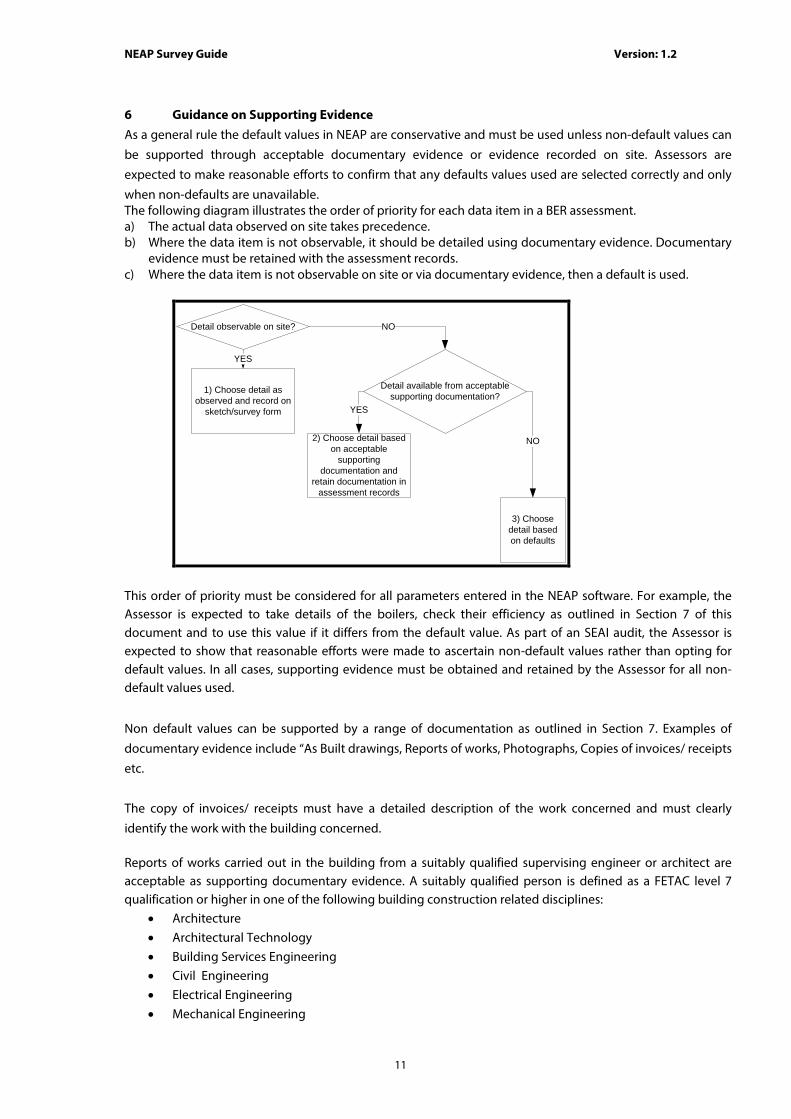
6 Guidance on Supporting Evidence As a general rule the default values in NEAP are conservative and must be used unless non-default values can
be supported through acceptable documentary evidence or evidence recorded on site. Assessors are
expected to make reasonable efforts to confirm that any defaults values used are selected correctly and only
when non-defaults are unavailable. The following diagram illustrates the order of priority for each data item in a BER assessment. a) The actual data observed on site takes precedence. b) Where the data item is not observable, it should be detailed using documentary evidence. Documentary
evidence must be retained with the assessment records. c) Where the data item is not observable on site or via documentary evidence, then a default is used.
Detail observable on site?
1) Choose detail as observed and record on
sketch/survey form
YES
2) Choose detail based on acceptable
supporting documentation and
retain documentation in assessment records
Detail available from acceptablesupporting documentation?
NO
YES
3) Choose detail based on defaults
NO
This order of priority must be considered for all parameters entered in the NEAP software. For example, the Assessor is expected to take details of the boilers, check their efficiency as outlined in Section 7 of this document and to use this value if it differs from the default value. As part of an SEAI audit, the Assessor is expected to show that reasonable efforts were made to ascertain non-default values rather than opting for default values. In all cases, supporting evidence must be obtained and retained by the Assessor for all non-default values used.
Non default values can be supported by a range of documentation as outlined in Section 7. Examples of
documentary evidence include “As Built drawings, Reports of works, Photographs, Copies of invoices/ receipts
etc.
The copy of invoices/ receipts must have a detailed description of the work concerned and must clearly
identify the work with the building concerned. Reports of works carried out in the building from a suitably qualified supervising engineer or architect are acceptable as supporting documentary evidence. A suitably qualified person is defined as a FETAC level 7 qualification or higher in one of the following building construction related disciplines:
• Architecture • Architectural Technology • Building Services Engineering • Civil Engineering • Electrical Engineering • Mechanical Engineering
NEAP Survey Guide Version: 1.2
12
• Quantity Surveying Such reports need to provide sufficient detail for the NEAP entry in question. For example, for retrofitted insulation, the invoice/receipt or report should detail the property address, material type, thickness and thermal conductivity, density of fill, etc. Thermal conductivity values for common building materials in new and existing buildings can be obtained from Building Regulation TGD L – Buildings Other Than Dwellings (Table A1) or from CIBSE Guide A. For existing and new-provisional buildings, Building Regulation TGD L (Table A2) or CIBSE Guide A may be used to determine the thermal conductivities for insulation products; however the preferred option is that thermal conductivity values are obtained for specific insulation products and the data should be obtained from accredited test data (for example an Agrement Certificate from the NSAI) in compliance with the relevant standards in TGD L. For new-final BERs, thermal conductivity values for insulation products must be obtained from accredited test data to the relevant standards in TGD L.
General Guidance on the Calculation of U-values to the relevant standards is contained in Report BR 443
“Conventions for U-value Calculations” 2006. For building elements and components generally, the method
of calculating U-values is specified in I.S. EN ISO 6946: 1997. U-values of components involving heat transfer
to the ground, e.g. ground floors with or without floor voids, basement walls, are calculated by the method
specified in I.S. EN ISO 13370: 1999. Software packages to perform U-value calculations for different building
elements in accordance with the relevant standards above are readily available. Details, such as element
thicknesses, thermal conductivities and resistances, used in carrying out U-value calculations must be
retained in the BER assessment records by the BER Assessor.
Where there is adequate documentary evidence to support a non-default U-value, a non-default km value
must also be used based on the makeup of the construction. The km value is calculated in compliance with
CEN standard: EN 13790 using the method in 7.4.1 of the iSBEM User Guide. The km value is the effective
thermal capacity of an element and accounts for the time it takes for heat to flow in or out of the building
fabric. Refer to Section A4.12 for details on calculation of km values.
6.1 Non Default Efficiency Data
The following outlines acceptable sources of non default efficiency data for use in conjunction with the Non-Domestic Building Services Compliance Guide: 2010: • Performance data on “CE marked” literature is acceptable provided that the literature refers to the
relevant test performance standard.
• Literature from manufacturer referencing the efficiency and relevant test performance standard.
• Accredited Test certificates clearly relating to the product in question or as verified by the manufacturer/ supplier as having the same performance as the installed product, must comply with the following:
o Installation instructions in the test certificate on which the stated performance depends must be adhered to;
o Test certificates must be in English or be accompanied by a certified English translation. The translation can be from the accredited test house or from a professional translator listed by the Irish Translators and Interpreters Association or international equivalent;
o The relevant test performance standard must be stated on the test certificate; o The test laboratory must be accredited. This may be demonstrated as follows:
The governing accreditation body for the test laboratory can be found under http://www.european-accreditation.org/ . This governing body may list the test laboratory as accredited;
The accredited laboratory may be found under http://ec.europa.eu/enterprise/newapproach/nando/ .
NEAP Survey Guide Version: 1.2
13
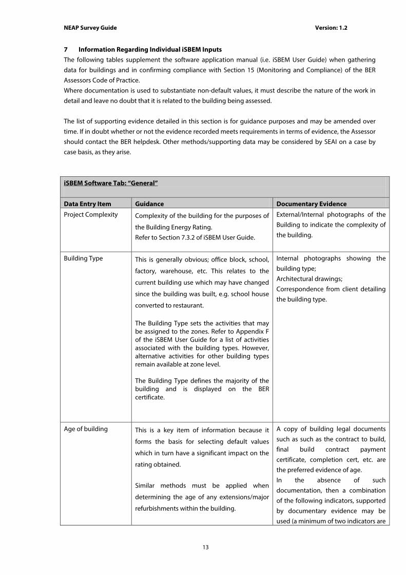
7 Information Regarding Individual iSBEM Inputs The following tables supplement the software application manual (i.e. iSBEM User Guide) when gathering
data for buildings and in confirming compliance with Section 15 (Monitoring and Compliance) of the BER
Assessors Code of Practice.
Where documentation is used to substantiate non-default values, it must describe the nature of the work in
detail and leave no doubt that it is related to the building being assessed.
The list of supporting evidence detailed in this section is for guidance purposes and may be amended over
time. If in doubt whether or not the evidence recorded meets requirements in terms of evidence, the Assessor
should contact the BER helpdesk. Other methods/supporting data may be considered by SEAI on a case by
case basis, as they arise.
iSBEM Software Tab: “General”
Data Entry Item Guidance Documentary Evidence
Project Complexity Complexity of the building for the purposes of
the Building Energy Rating.
Refer to Section 7.3.2 of iSBEM User Guide.
External/Internal photographs of the
Building to indicate the complexity of
the building.
Building Type This is generally obvious; office block, school,
factory, warehouse, etc. This relates to the
current building use which may have changed
since the building was built, e.g. school house
converted to restaurant.
The Building Type sets the activities that may be assigned to the zones. Refer to Appendix F of the iSBEM User Guide for a list of activities associated with the building types. However, alternative activities for other building types remain available at zone level. The Building Type defines the majority of the building and is displayed on the BER certificate.
Internal photographs showing the
building type;
Architectural drawings;
Correspondence from client detailing
the building type.
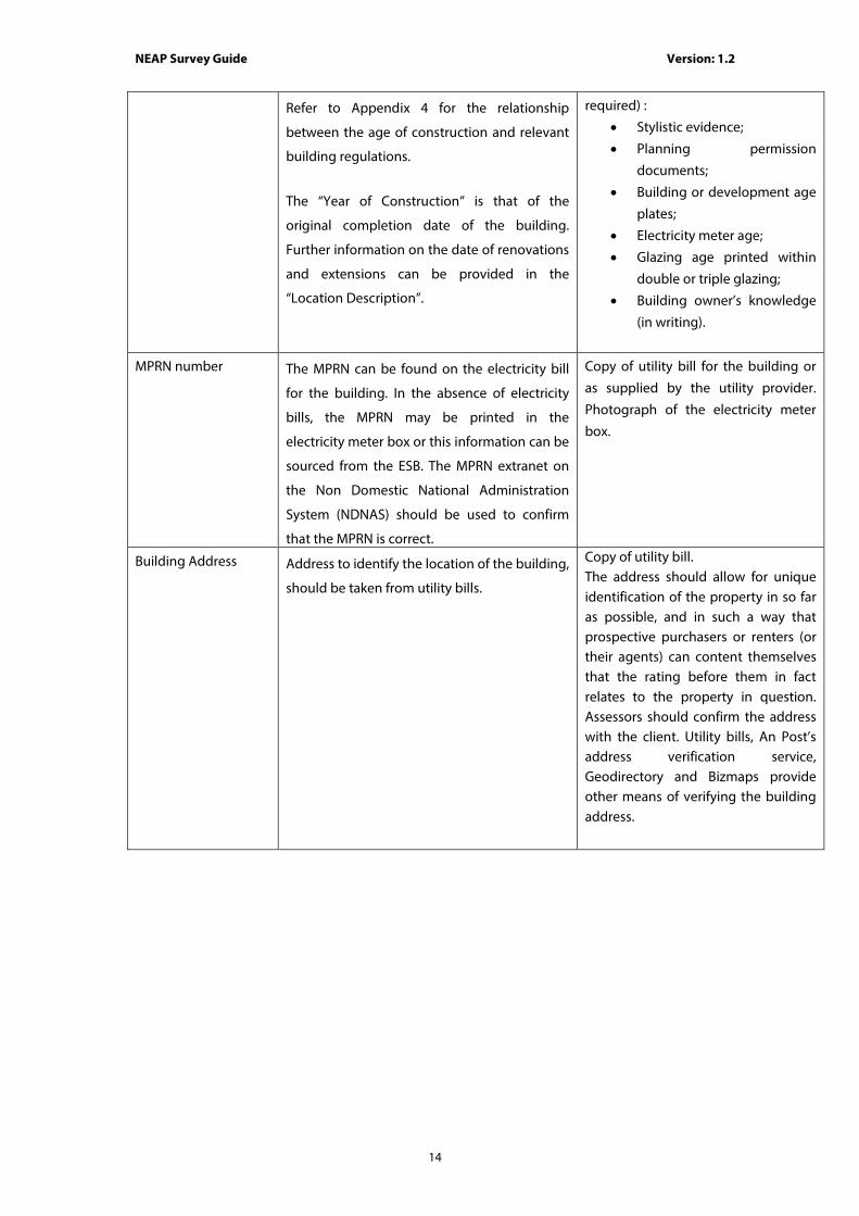
Age of building This is a key item of information because it
forms the basis for selecting default values
which in turn have a significant impact on the
rating obtained.
Similar methods must be applied when
determining the age of any extensions/major
refurbishments within the building.
A copy of building legal documents
such as such as the contract to build,
final build contract payment
certificate, completion cert, etc. are
the preferred evidence of age.
In the absence of such
documentation, then a combination
of the following indicators, supported
by documentary evidence may be
used (a minimum of two indicators are
NEAP Survey Guide Version: 1.2
14
Refer to Appendix 4 for the relationship
between the age of construction and relevant
building regulations.
The “Year of Construction” is that of the
original completion date of the building.
Further information on the date of renovations
and extensions can be provided in the
“Location Description”.
required) :
• Stylistic evidence;
• Planning permission
documents;
• Building or development age
plates;
• Electricity meter age;
• Glazing age printed within
double or triple glazing;
• Building owner’s knowledge
(in writing).
MPRN number The MPRN can be found on the electricity bill
for the building. In the absence of electricity
bills, the MPRN may be printed in the
electricity meter box or this information can be
sourced from the ESB. The MPRN extranet on
the Non Domestic National Administration
System (NDNAS) should be used to confirm
that the MPRN is correct.
Copy of utility bill for the building or
as supplied by the utility provider.
Photograph of the electricity meter
box.
Building Address Address to identify the location of the building,
should be taken from utility bills.
Copy of utility bill. The address should allow for unique identification of the property in so far as possible, and in such a way that prospective purchasers or renters (or their agents) can content themselves that the rating before them in fact relates to the property in question. Assessors should confirm the address with the client. Utility bills, An Post’s address verification service, Geodirectory and Bizmaps provide other means of verifying the building address.
NEAP Survey Guide Version: 1.2
15
iSBEM Software Tab: “Project Database”
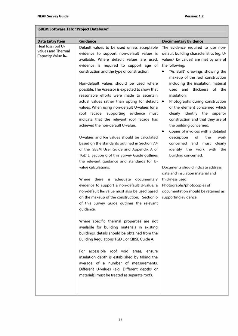
Data Entry Item Guidance Documentary Evidence Heat loss roof U-values and Thermal Capacity Value km
Default values to be used unless acceptable
evidence to support non-default values is
available. Where default values are used,
evidence is required to support age of
construction and the type of construction.
Non-default values should be used where
possible. The Assessor is expected to show that
reasonable efforts were made to ascertain
actual values rather than opting for default
values. When using non-default U-values for a
roof facade, supporting evidence must
indicate that the relevant roof facade has
achieved the non-default U-value.
U-values and km values should be calculated
based on the standards outlined in Section 7.4
of the iSBEM User Guide and Appendix A of
TGD L. Section 6 of this Survey Guide outlines
the relevant guidance and standards for U-
value calculations.
Where there is adequate documentary
evidence to support a non-default U-value, a
non-default km value must also be used based
on the makeup of the construction. Section 6
of this Survey Guide outlines the relevant
guidance.
Where specific thermal properties are not
available for building materials in existing
buildings, details should be obtained from the
Building Regulations TGD L or CIBSE Guide A.
For accessible roof void areas, ensure
insulation depth is established by taking the
average of a number of measurements.
Different U-values (e.g. Different depths or
materials) must be treated as separate roofs.
The evidence required to use non-
default building characteristics (eg, U-
values/ km values) are met by one of
the following:
• “As Built” drawings showing the
makeup of the roof construction
including the insulation material
used and thickness of the
insulation;
• Photographs during construction
of the element concerned which
clearly identify the superior
construction and that they are of
the building concerned;
• Copies of invoices with a detailed
description of the work
concerned and must clearly
identify the work with the
building concerned.
Documents should indicate address,
date and insulation material and
thickness used.
Photographs/photocopies of
documentation should be retained as
supporting evidence.

NEAP Survey Guide Version: 1.2
16
Wall U-values and Thermal Capacity Value km
Default values to be used unless acceptable
evidence to support non-default values is
available. Where default values are used,
evidence is required to support age of
construction and the type of construction.
Non-default values should be used where
possible. The Assessor is expected to show that
reasonable efforts were made to ascertain
actual values rather than opting for default
values. When using non-default U-values,
supporting evidence must indicate that the
entire wall has achieved the non-default
U-value.
U-values and km values should be calculated
based on the standards outlined in Section 7.4
of the iSBEM User Guide and Appendix A of
TGD L. Section 6 of this Survey Guide outlines
the relevant guidance and standards for U-
value calculations.
Where there is adequate documentary
evidence to support a non-default U-value, a
non-default km value must also be used based
on the makeup of the construction.
Where specific thermal properties are not
available for building materials in existing
buildings, details should be obtained from the
Building Regulations TGD L or CIBSE Guide A.
The presence of additional insulation must be
supported by appropriate documentary
evidence.
The evidence required to use non-
default building characteristics (eg, U-
values/ km values) are met by one of
the following:
• “As Built” drawings showing the
makeup of the wall construction
including the insulation material
used and thickness of the
insulation;
• Photographs during construction
of the element concerned which
clearly identify the superior
construction and that they are of
the building concerned;
• Copies of invoices with a detailed
description of the work
concerned and must clearly
identify the work with the
building concerned.
Documents should indicate address,
date and insulation material and
thickness used.
Photographs / photocopies of
documentation should be retained as
supporting evidence.

NEAP Survey Guide Version: 1.2
17
Floor U-values and Thermal Capacity Value km
Default values to be used unless acceptable
evidence to support non-default values is
available. Where default values are used,
evidence is required to support age of
construction and the type of construction.
Non-default values should be used where
possible. The Assessor is expected to show that
reasonable efforts were made to ascertain
actual values rather than opting for default
values. When using non-default U-values,
supporting evidence must indicate that the
entire floor has achieved the non-default
U-value.
U-values and km values must be calculated
based on the standards outlined in Section 7.4
of the iSBEM User Guide and Appendix A of
TGD L. Section 6 of this Survey Guide outlines
the relevant guidance and standards for U-
value calculations.
Where there is adequate documentary
evidence to support a non-default U-value, a
non-default km value must also be used based
on the makeup of the construction.
Where specific thermal properties are not
available for building materials in existing
buildings, details should be obtained from the
Building Regulations TGD L or CIBSE Guide A.
The evidence required to use non-
default building characteristics (eg U-
values/ km values) is met by one of the
following:
• “As Built” drawings showing the
makeup of the floor construction
including the insulation material
used and thickness of the
insulation;
• Photographs during construction
of the element concerned which
clearly identify the superior
construction and that they are of
the building concerned;
• Copies of invoices with a detailed
description of the work
concerned and must clearly
identify the work with the
building concerned.
Documents should indicate address,
date and insulation material and
thickness used.
Photographs / photocopies of
documentation should be retained as
supporting evidence.

NEAP Survey Guide Version: 1.2
18
Door U-Value and Thermal Capacity Value km
Default values to be used unless acceptable
evidence to support non-default values is
available. Where default values are used,
evidence is required to support age of
construction and the type of door installed.
Non-default values should be used where
possible. The Assessor is expected to show that
reasonable efforts were made to ascertain
actual values rather than opting for default
values.
U-values and km values must be calculated
based on the standards outlined in Section 7.4
of the iSBEM User Guide and Appendix A of
TGD L. Section 6 of this Survey Guide outlines
the relevant guidance and standards for U-
value calculations.
Where there is adequate documentary
evidence to support a non-default U-value, a
non-default km value must also be used based
on the makeup of the construction.
Where specific thermal properties are not
available for building materials in existing
buildings, details should be obtained from the
Building Regulations TGD L or CIBSE Guide A.
The evidence required to use non-
default building characteristics (eg, U-
values/ km values) are met by one of
the following:
• “As Built” drawings/ specification
detailing the Door make and
model and copies of certified U-
values;
• Copies of invoices with technical
characteristics of the door, clearly
identifying that it relates to the
building concerned.
Documents should indicate building
address, date and details of the door
in question.
Photographs / photocopies of
documentation should be retained as
supporting evidence.
NEAP Survey Guide Version: 1.2
19
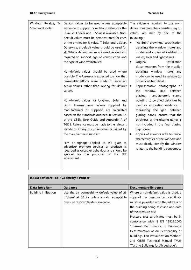
Window U-value, T-
Solar and L-Solar
Default values to be used unless acceptable
evidence to support non-default values for the
U-value, T Solar and L Solar is available. Non-
default values must be demonstrated for each
of the entries for U-value, T-Solar and L-Solar.
Otherwise, a default value should be used for
all. Where default values are used, evidence is
required to support age of construction and
the type of window installed.
Non-default values should be used where
possible. The Assessor is expected to show that
reasonable efforts were made to ascertain
actual values rather than opting for default
values.
Non-default values for U-values, Solar and
Light Transmittance values supplied by
manufacturers or suppliers are calculated
based on the standards outlined in Section 7.4
of the iSBEM User Guide and Appendix A of
TGD L. Reference must be made to the relevant
standards in any documentation provided by
the manufacturer/ supplier.
Film or signage applied to the glass to advertise/ promote services or products is regarded as occupier behaviour and should be ignored for the purposes of the BER assessment.
The evidence required to use non-
default building characteristics (eg, U-
values) are met by one of the
following:
• “As Built” drawings/ specification
detailing the window make and
model and copies of certified U-
values, solar and light values;
• Original installation
documentation from the installer
detailing window make and
model can be used if available (to
obtain certified data);
• Representative photographs of
the window, gap between
glazing, manufacturer’s stamp
pointing to certified data can be
used as supporting evidence. If
measuring the gap between
glazing panes, ensure that the
thickness of the glazing panes is
not included in the final glazing
gap figure;
• Copies of invoices with technical
characteristics of the window and
must clearly identify the window
relates to the building concerned.
iSBEM Software Tab: “Geometry > Project”
Data Entry Item Guidance Documentary Evidence
Building Infiltration Use the air permeability default value of 25
m3/h/m2 at 50 Pa unless a valid acceptable
pressure test certificate is available.
Where a non-default value is used, a
copy of the pressure test certificate
must be provided with the address of
the building being assessed and date
of the pressure test.
Pressure test certificates must be in
compliance with IS EN 13829:2000
“Thermal Performance of Buildings;
Determination of Air Permeability of
Buildings: Fan Pressurization Method”
and CIBSE Technical Manual TM23
“Testing Buildings for Air Leakage”.
NEAP Survey Guide Version: 1.2
20
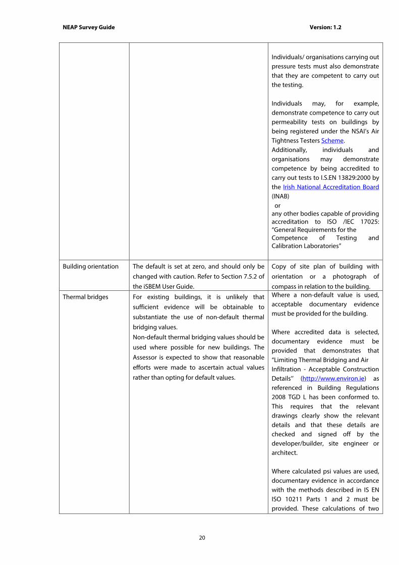
Individuals/ organisations carrying out pressure tests must also demonstrate that they are competent to carry out the testing. Individuals may, for example, demonstrate competence to carry out permeability tests on buildings by being registered under the NSAI’s Air Tightness Testers Scheme. Additionally, individuals and organisations may demonstrate competence by being accredited to carry out tests to I.S.EN 13829:2000 by the Irish National Accreditation Board (INAB) or any other bodies capable of providing accreditation to ISO /IEC 17025: “General Requirements for the Competence of Testing and Calibration Laboratories”
Building orientation The default is set at zero, and should only be
changed with caution. Refer to Section 7.5.2 of
the iSBEM User Guide.
Copy of site plan of building with
orientation or a photograph of
compass in relation to the building.
Thermal bridges For existing buildings, it is unlikely that
sufficient evidence will be obtainable to
substantiate the use of non-default thermal
bridging values.
Non-default thermal bridging values should be
used where possible for new buildings. The
Assessor is expected to show that reasonable
efforts were made to ascertain actual values
rather than opting for default values.
Where a non-default value is used, acceptable documentary evidence must be provided for the building. Where accredited data is selected, documentary evidence must be provided that demonstrates that “Limiting Thermal Bridging and Air Infiltration - Acceptable Construction Details’’ (http://www.environ.ie) as referenced in Building Regulations 2008 TGD L has been conformed to. This requires that the relevant drawings clearly show the relevant details and that these details are checked and signed off by the developer/builder, site engineer or architect. Where calculated psi values are used, documentary evidence in accordance with the methods described in IS EN ISO 10211 Parts 1 and 2 must be provided. These calculations of two

NEAP Survey Guide Version: 1.2
21
dimensional or three dimensional heat flow require the use of numerical modeling software. To be acceptable, numerical modeling software should model the validation examples in IS EN ISO 10211 with results that agree with the stated values of temperature and heat flow within the tolerance indicated in the standard for these examples. Several packages are available that meet this requirement. Detailed guidance on decisions regarding specific input to the modeling software and the determination of certain quantities from the output of the software is contained in BRE Report BR 497 Conventions for calculating linear thermal transmittance and temperature factors. This guidance should be followed in carrying out modeling work so that different users of the same software package and users of different software packages can obtain correct and consistent
results. TGD L Section D2 requires that Ψ values are calculated in accordance with I.S. EN 10211. Certification of the detail by a member of the NSAI Thermal Modellers’ Certification Scheme is a means of meeting the requirements in TGD L and NEAP for calculation of Ψ values.
iSBEM Software Tab: “Geometry > Zones > General”
Data Entry Item Guidance Documentary Evidence
HVAC System The use of default HVAC systems is detailed in
Appendix 4 and Appendix 7. The appendices
deal specifically with the following
circumstances:
- Shell and Core Buildings
- No HVAC present in the building/ zone
For further detail on default HVAC systems
refer to 7.5.3 of the iSBEM User Guide.
The evidence required in order to use
non-default building characteristics is
met by one of the following in
conjunction with the plantroom
survey and ceiling void details:
• Copy of as built HVAC drawings
and specifications;
• Copy of technical details from
operational and maintenance
manuals;

NEAP Survey Guide Version: 1.2
22
The BER is based on non default HVAC systems
where there is sufficient evidence available. As
outlined in Section 6 the Assessor is expected
to show that reasonable efforts were made to
ascertain non-default values rather than
opting for default values.
• Representative photographs of
the HVAC system.
Building Type/
Activity
The activity specified sets default parameters
which the tool uses to calculate the energy
consumption. These parameters include
temperature set points, heat gains from people
and equipment, required illuminance, and
fresh air requirements amongst others.
For details Refer to 7.5.3 of the iSBEM User
Guide.
In combination with the floor by floor
sketches /architectural drawings
marked up to show zones the
following should be provided:
• Survey Form;
• Note on basis used to define
zones.
Area Floor area of zone.
Refer to Section 3.4 Measurement and Other
Conventions and Section 7.5.3 of the iSBEM
User Guide.
Floor by floor sketches with
dimensions and calculations
or
Architectural drawings with
dimensions and calculations marked
up to show zones.
Height Height of zone
Refer to Section 3.4 Measurement and Other
Conventions and Section 7.5.3 of the iSBEM
User Guide.
Refer to Appendix 6 of the NEAP Survey Guide
for examples of zone height calculation.
Building sketches with dimensions,
calculations and Survey Form
or
Architectural drawings with
dimensions, calculations and Survey
Form.
Building sketches/ architectural
drawings should show the depth of all
components, including floor slabs,
floor voids, ceiling voids etc.
Zone Infiltration Use the air permeability default value of 25
m3/h/m2 at 50 Pa unless a valid pressure test
certificate is available.
Where a non-default value is used, a
copy of the pressure test certificate
must be provided with the address of
the building being assessed and date
of the pressure test.
Pressure test certificates must be in
compliance with IS EN 13829:2000
“Thermal Performance of Buildings;
Determination of Air Permeability of
Buildings: Fan Pressurization Method”
and CIBSE Technical Manual TM23
“Testing Buildings for Air Leakage”.
Refer to Building Infiltration for
guidance on individuals/

NEAP Survey Guide Version: 1.2
23
organisations carrying out tests.
iSBEM Software Tab: “Geometry > Envelope”
Data Entry Item Guidance Documentary Evidence
Name Refer to Section 3.6 Nomenclature in iSBEM
User Guide for guidance. Not applicable.
Zone Zone that envelope element is part of. Floor by floor sketches with
dimensions and Survey Form
or
Architectural drawings with
dimensions and marked up to show
zones and Survey Form.
Type of Envelope Choose between wall, floor/ceiling and roof. Not applicable.
Construction Choose from Constructions set up in Project
Database for envelope type.
Floor by floor sketches with
dimensions and Survey Form and
photographs
or
Architectural drawings with
dimensions and marked up to show
zones and Survey Form and
photographs.
Connects Space to Choose what conditions apply to the other
side of the wall, floor/ceiling or roof.
Refer to Section 7.5.4 of iSBEM User Guide for
definitions.
Refer to Appendix 8 for further guidance.
Floor by floor sketches with
dimensions and Survey Form
or
Architectural drawings with
dimensions and marked up to show
zones and Survey Form.
Orientation Select from one of the available options. Copy of site plan or sketch of building
with orientation and photograph of
compass in relation to the building.
Area Area of envelope inclusive of any windows/
doors.
Refer to Section 3.4 of iSBEM User Guide for
measurement conventions.
Floor by floor sketches with
dimensions, calculations and Survey
Form
or
Architectural drawings with
dimensions, calculations and marked
up to show zones and Survey Form.
Additional Thermal
Bridges
For existing buildings, it is unlikely that
sufficient evidence will be obtainable to
substantiate the use of non-default thermal
bridging psi values.
Non-default thermal bridging values should be
used where possible for new buildings. The
Assessor is expected to show that reasonable
Where a non-default value is used,
acceptable documentary evidence
must be provided for the building.
Refer to thermal bridging in section
iSBEM Software Tab: “Geometry > Project” for guidance on
documentary evidence required.

NEAP Survey Guide Version: 1.2
24
efforts were made to ascertain actual values
rather than opting for default values.
iSBEM Software Tab: “Geometry > Doors”
Data Entry Item Guidance Documentary Evidence
Name Refer to Section 3.6 Nomenclature in iSBEM
User Guide for guidance.
Not applicable.
In Envelope Envelope that Door is part of. Floor by floor sketches with
dimensions and Survey Form
or
Architectural drawings with
dimensions and marked up to show
zones and Survey Form.
Type Choose between High Usage Entrance,
Personnel, and Vehicle Access Doors.
Not applicable.
Construction Choose from Constructions set up in Project
Database for door type.
Floor by floor sketches with doors
identified and Survey Form and
photographs
or
Architectural drawings with doors
identified and marked up to show
zones and Survey Form and
photographs.
Area Area of structural opening in wall including
frame.
Refer to Section 3.4 of iSBEM User Guide for
measurement conventions.
Building sketches with dimensions
and Survey Form
or
Architectural drawings with
dimensions and Survey Form.
iSBEM Software Tab: “Geometry > Windows and Rooflights”
Data Entry Item Guidance Documentary Evidence
Name Refer to Section 3.6 Nomenclature in iSBEM
User Guide for guidance.
Not applicable.
In Envelope Envelope that window/rooflight is part of. Floor by floor sketches with
dimensions and Survey Form
or
Architectural drawings with
dimensions and marked up to show
zones and Survey Form.
Glazing Type Choose between the glazing types defined in
Project Database or default glazing.
Floor by floor sketches with glazing
type identified and Survey Form and

NEAP Survey Guide Version: 1.2
25
photographs
or
Architectural drawings with glazing
type identified and marked up to
show zones and Survey Form and
photographs.
Area Area of structural opening in wall/roof
including frame.
Refer to Section 3.4 of iSBEM User Guide for
measurement conventions.
Building sketches with dimensions
and Survey Form
or
Architectural drawings with
dimensions and Survey Form.
Surface Area Ratio This is the “developed area to projected area”
ratio for the window or rooflight as defined in
Section 7.5.5 of iSBEM User Guide.
Building sketches with dimensions
and Survey Form
or
Architectural drawings with
dimensions and Survey Form.
Display Window
Tickbox
This is an area of glazing intended for the display of products or services on offer within the building, positioned: • At external perimeter of the building; and • At an access level and immediately
adjacent to a pedestrian thoroughfare. There should be no permanent workspace within one glazing height of the perimeter. Glazing more than 3m above such an access level should not be considered part of the display window except: • Where the products on display require a
greater height of glazing; • In cases of building work involving
changes to the façade and glazing requiring planning consent, where planners should have discretion to require a greater height of glazing; eg to fit in with surrounding buildings or to match the character of the existing façade.
Building sketches with dimensions
and Survey Form
or
Architectural drawings with
dimensions and Survey Form.
Area Ratio Covered This is the ratio of the roof area covered by an
array of rooflights to the total area of the
rooflight glazing.
Refer to Section 7.5.5 of iSBEM User Guide for
definition.
Building sketches with dimensions
and Survey Form
or
Architectural drawings with
dimensions and Survey Form.
Shading System Choose from User-moveable external
protection, Automatically-controlled external
protection, or All other cases.
Refer to Section 7.5.5 of iSBEM User Guide for
definition.
Building sketches with dimensions
and Survey Form and photographs
or
Architectural drawings with
dimensions and Survey Form and
photographs.
Transmission Factor This is the fraction of light transmitted through
that specific window after accounting for
shading from overhangs and fins.
Building sketches with dimensions
and Survey Form and photographs
or
NEAP Survey Guide Version: 1.2
26
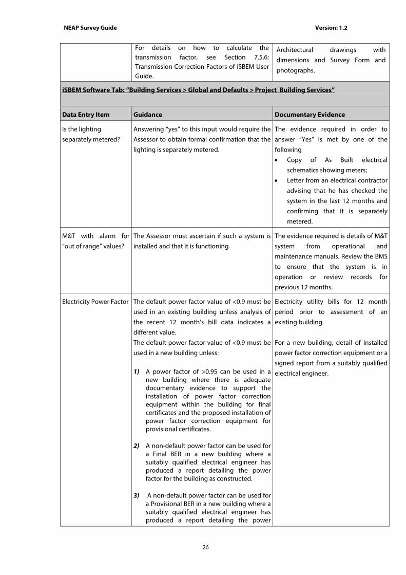
For details on how to calculate the transmission factor, see Section 7.5.6: Transmission Correction Factors of iSBEM User Guide.
Architectural drawings with
dimensions and Survey Form and
photographs.
iSBEM Software Tab: “Building Services > Global and Defaults > Project Building Services”
Data Entry Item Guidance Documentary Evidence
Is the lighting
separately metered?
Answering “yes” to this input would require the
Assessor to obtain formal confirmation that the
lighting is separately metered.
The evidence required in order to
answer “Yes” is met by one of the
following
• Copy of As Built electrical
schematics showing meters;
• Letter from an electrical contractor
advising that he has checked the
system in the last 12 months and
confirming that it is separately
metered.
M&T with alarm for
“out of range” values?
The Assessor must ascertain if such a system is
installed and that it is functioning.
The evidence required is details of M&T
system from operational and
maintenance manuals. Review the BMS
to ensure that the system is in
operation or review records for
previous 12 months.
Electricity Power Factor The default power factor value of <0.9 must be
used in an existing building unless analysis of
the recent 12 month’s bill data indicates a
different value.
The default power factor value of <0.9 must be
used in a new building unless:
1) A power factor of >0.95 can be used in a
new building where there is adequate documentary evidence to support the installation of power factor correction equipment within the building for final certificates and the proposed installation of power factor correction equipment for provisional certificates.
2) A non-default power factor can be used for a Final BER in a new building where a suitably qualified electrical engineer has produced a report detailing the power factor for the building as constructed.
3) A non-default power factor can be used for
a Provisional BER in a new building where a suitably qualified electrical engineer has produced a report detailing the power
Electricity utility bills for 12 month
period prior to assessment of an
existing building.
For a new building, detail of installed
power factor correction equipment or a
signed report from a suitably qualified
electrical engineer.
NEAP Survey Guide Version: 1.2
27
factor for the building as per the design.
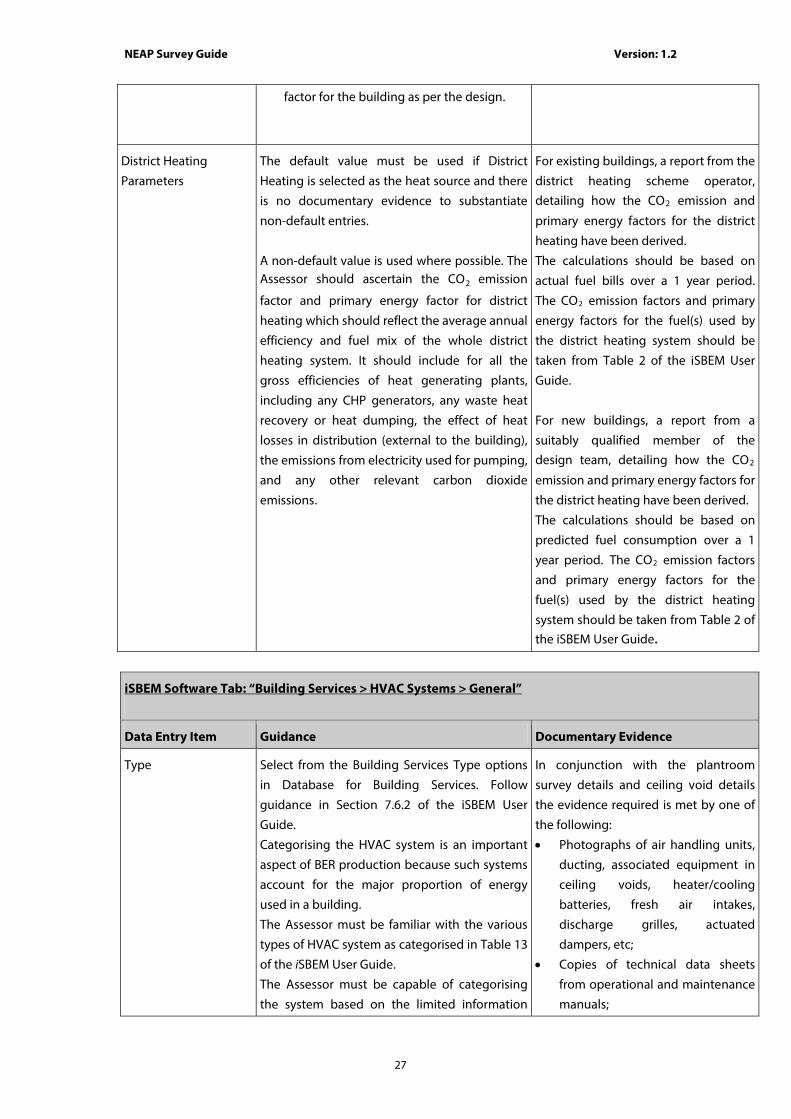
District Heating
Parameters
The default value must be used if District
Heating is selected as the heat source and there
is no documentary evidence to substantiate
non-default entries.
A non-default value is used where possible. The Assessor should ascertain the CO2 emission
factor and primary energy factor for district
heating which should reflect the average annual
efficiency and fuel mix of the whole district
heating system. It should include for all the
gross efficiencies of heat generating plants,
including any CHP generators, any waste heat
recovery or heat dumping, the effect of heat
losses in distribution (external to the building),
the emissions from electricity used for pumping,
and any other relevant carbon dioxide
emissions.
For existing buildings, a report from the
district heating scheme operator, detailing how the CO2 emission and
primary energy factors for the district
heating have been derived.
The calculations should be based on
actual fuel bills over a 1 year period. The CO2 emission factors and primary
energy factors for the fuel(s) used by
the district heating system should be
taken from Table 2 of the iSBEM User
Guide.
For new buildings, a report from a
suitably qualified member of the design team, detailing how the CO2
emission and primary energy factors for
the district heating have been derived.
The calculations should be based on
predicted fuel consumption over a 1
year period. The CO2 emission factors
and primary energy factors for the
fuel(s) used by the district heating
system should be taken from Table 2 of the iSBEM User Guide.
iSBEM Software Tab: “Building Services > HVAC Systems > General”
Data Entry Item Guidance Documentary Evidence
Type Select from the Building Services Type options
in Database for Building Services. Follow
guidance in Section 7.6.2 of the iSBEM User
Guide.
Categorising the HVAC system is an important
aspect of BER production because such systems
account for the major proportion of energy
used in a building.
The Assessor must be familiar with the various
types of HVAC system as categorised in Table 13
of the iSBEM User Guide.
The Assessor must be capable of categorising
the system based on the limited information
In conjunction with the plantroom
survey details and ceiling void details
the evidence required is met by one of
the following:
• Photographs of air handling units,
ducting, associated equipment in
ceiling voids, heater/cooling
batteries, fresh air intakes,
discharge grilles, actuated
dampers, etc;
• Copies of technical data sheets
from operational and maintenance
manuals;
NEAP Survey Guide Version: 1.2
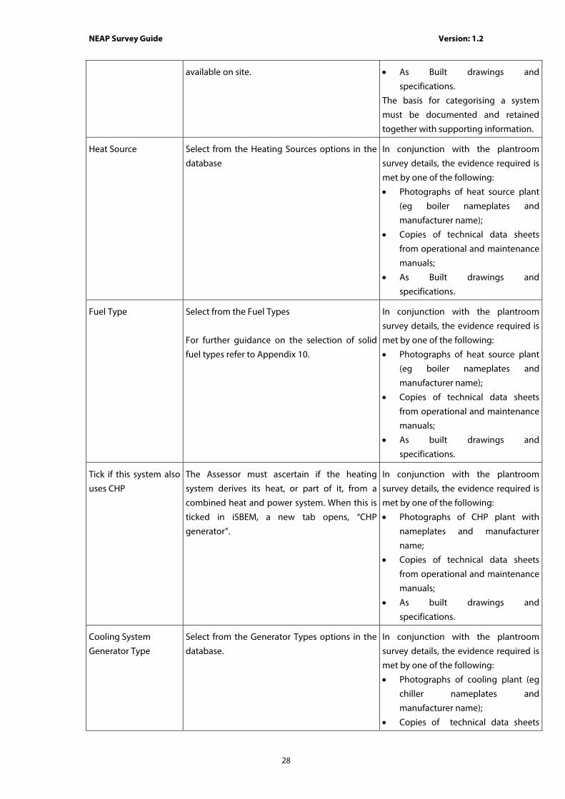
28
available on site.
• As Built drawings and
specifications.
The basis for categorising a system
must be documented and retained
together with supporting information.
Heat Source Select from the Heating Sources options in the
database
In conjunction with the plantroom
survey details, the evidence required is
met by one of the following:
• Photographs of heat source plant
(eg boiler nameplates and
manufacturer name);
• Copies of technical data sheets
from operational and maintenance
manuals;
• As Built drawings and
specifications.
Fuel Type Select from the Fuel Types
For further guidance on the selection of solid
fuel types refer to Appendix 10.
In conjunction with the plantroom
survey details, the evidence required is
met by one of the following:
• Photographs of heat source plant
(eg boiler nameplates and
manufacturer name);
• Copies of technical data sheets
from operational and maintenance
manuals;
• As built drawings and
specifications.
Tick if this system also
uses CHP
The Assessor must ascertain if the heating
system derives its heat, or part of it, from a
combined heat and power system. When this is
ticked in iSBEM, a new tab opens, “CHP
generator”.
In conjunction with the plantroom
survey details, the evidence required is
met by one of the following:
• Photographs of CHP plant with
nameplates and manufacturer
name;
• Copies of technical data sheets
from operational and maintenance
manuals;
• As built drawings and
specifications.
Cooling System
Generator Type
Select from the Generator Types options in the
database.
In conjunction with the plantroom
survey details, the evidence required is
met by one of the following:
• Photographs of cooling plant (eg
chiller nameplates and
manufacturer name);
• Copies of technical data sheets

NEAP Survey Guide Version: 1.2
29
from operational and maintenance
manuals;
• As built drawings and
specifications.
Ventilation Heat
Recovery
The heat recovery system may be incorporated
within the air handling unit(s) or it may be
external.
The Assessor must establish whether or not heat
recovery is fitted and to make reasonable efforts
to ascertain its seasonal efficiency.
The default value must be used for efficiency if
there is no documentary evidence to
substantiate non-default entries.
A non-default value should be used where
possible. Non-default efficiency values must be
in compliance with Section 10.5 of “Non-
Domestic Building Services Compliance Guide:
2010” published by CLG in the UK.
Non-default efficiencies may be obtained from
the following sources as per Section 6.1:
• Performance data on “CE marked”
literature is acceptable provided that the literature refers to the relevant test performance standard.
• Literature from manufacturer referencing the efficiency and relevant test performance standard.
• Accredited Test certificates to the relevant test performance standard
In conjunction with the plantroom
survey details, the evidence required is
met by one of the following:
• Photographs of heat recovery unit;
• Copies of technical data sheets
from operational and maintenance
manuals
• Sources of efficiency as outlined in
“Guidance” and Section 6.1;
• As Built drawings and
specifications.

NEAP Survey Guide Version: 1.2
30
iSBEM Software Tab: “Building Services > HVAC Systems > Heating”
Data Entry Item Guidance Documentary Evidence
Does it qualify for
ECA/ACA?
Check the equipment concerned at
http://www.SEAI.ie/Your_Business/Accelerated_
Capital_Allowance or http://www.eca.gov.uk/ .
Take note of the specific equipment
make and model number and show
corresponding details on ACA
webpage (or ECA, the UK equivalent).
Include a snapshot of the relevant page
from the website. A web link to the
page is not acceptable. ECA allows the
user to receive an automated email
with the product listing. ACA can
generate an Excel file with the product
listing. Both of these are acceptable as
supporting evidence for this entry.
Do you know the
effective heat
generating seasonal
efficiency?
It is important to note that there is a difference
between the “as tested” efficiency of a boiler,
the “gross seasonal” efficiency and the “Effective
Heat Generating Seasonal Efficiency” as
required in iSBEM.
Non-default efficiency values must be
calculated in compliance with “Non-Domestic
Building Services Compliance Guide: 2010”
published by CLG in the UK.
Refer to Appendix 5 of this Survey Guide for
examples of how the Compliance Guide is used.
Heating efficiency credits are applied to the
“Seasonal Boiler Efficiency” to arrive at the
“Effective Heat Generating Seasonal Efficiency”
as called for in the iSBEM input screen. Refer to
the Non-Domestic Building Services Compliance
Guide: 2010 to determine if credits apply to the
efficiency of the system as installed in the
building being assessed.
Non-default efficiencies may be obtained from
the following sources as per Section 6.1:
• Performance data on “CE marked”
literature is acceptable provided that the literature refers to the relevant test performance standard.
• Literature from manufacturer referencing
In conjunction with the plantroom
survey details, the evidence required is
met by one of the following:
• Photographs of heat source plant
(eg boiler nameplates and
manufacturer name) and
manufacturer’s data sheets;
• Sources of efficiency as outlined in
“Guidance” and Section 6.1;
• Copies of technical data sheets
from operational and maintenance
manuals;
• As Built drawings and
specifications;
• Copies of control specifications/
schedules or historical data from
BMS demonstrating that the boiler
is operating in condensing mode
for 80% of the annual operating
hours.

NEAP Survey Guide Version: 1.2
31
iSBEM Software Tab: “Building Services > HVAC Systems > Heating”
Data Entry Item Guidance Documentary Evidence
the efficiency and relevant test performance standard.
• Accredited Test certificates to the relevant test performance standard
• ECA/ ACA websites, where technology has been tested to the relevant test performance standard.
The Assessor should use default values only if it
is not possible to obtain the heating source
efficiency data required and should have
evidence to substantiate this, such as
correspondence from heating source
manufacturer stating that efficiency is not
available.
Do you know the
generator radiant
efficiency?
For radiant heaters the Heat Generator Seasonal
Efficiency is equivalent to its thermal efficiency
(gross calorific value basis). For flued appliances
the thermal efficiency of the radiant heater will
be stated by the manufacturer of the radiant
heater having been measured according to the
test standards EN 1020 or EN 13842 as
applicable. The procedures in EN 1020 and EN
13842 yield a net efficiency - this must be
converted to a gross efficiency.
In conjunction with the plantroom
survey details, the evidence required is
met by one of the following:
• Photographs of heat source
plant(eg boiler nameplates and
manufacturer name) and
manufacturer’s data sheets;
• Sources of efficiency as outlined in
Section 6.1;
• Copies of technical data sheets
from operational and maintenance
manuals;
• As Built drawings and
specifications.
Tick if this HVAC
system uses variable
speed pumps.
The Assessor must examine the circulating
pumps to determine if they are variable speed
type. Manufacturer’s data sheets should assist in
this regard.
In conjunction with the plantroom
survey details, the evidence required is
met by one of the following:
• Photographs of pumps and
manufacturer’s data sheets;
• Copies of technical data sheets
from operational and maintenance
manuals;
• As Built drawings and
specifications.
Tick if this system also Refer to previous section “Building Services > Refer to previous section “Building
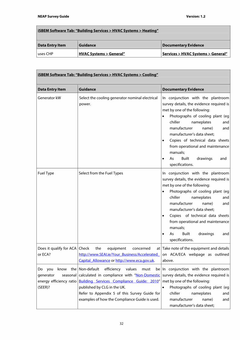
NEAP Survey Guide Version: 1.2
32
iSBEM Software Tab: “Building Services > HVAC Systems > Heating”
Data Entry Item Guidance Documentary Evidence
uses CHP HVAC Systems > General” Services > HVAC Systems > General”
iSBEM Software Tab: “Building Services > HVAC Systems > Cooling”
Data Entry Item Guidance Documentary Evidence
Generator kW Select the cooling generator nominal electrical
power.
In conjunction with the plantroom
survey details, the evidence required is
met by one of the following:
• Photographs of cooling plant (eg
chiller nameplates and
manufacturer name) and
manufacturer’s data sheet;
• Copies of technical data sheets
from operational and maintenance
manuals;
• As Built drawings and
specifications.
Fuel Type Select from the Fuel Types
In conjunction with the plantroom
survey details, the evidence required is
met by one of the following:
• Photographs of cooling plant (eg
chiller nameplates and
manufacturer name) and
manufacturer’s data sheet;
• Copies of technical data sheets
from operational and maintenance
manuals;
• As Built drawings and
specifications.
Does it qualify for ACA
or ECA?
Check the equipment concerned at
http://www.SEAI.ie/Your_Business/Accelerated_
Capital_Allowance or http://www.eca.gov.uk.
Take note of the equipment and details
on ACA/ECA webpage as outlined
above.
Do you know the
generator seasonal
energy efficiency ratio
(SEER)?
Non-default efficiency values must be
calculated in compliance with “Non-Domestic
Building Services Compliance Guide: 2010”
published by CLG in the UK.
Refer to Appendix 5 of this Survey Guide for
examples of how the Compliance Guide is used.
In conjunction with the plantroom
survey details, the evidence required is
met by one of the following:
• Photographs of cooling plant (eg
chiller nameplates and
manufacturer name) and
manufacturer’s data sheet;

NEAP Survey Guide Version: 1.2
33
Non-default efficiencies may be obtained from
the following sources:
• Performance data on “CE marked”
literature is acceptable provided that the literature refers to the relevant test performance standard.
• Literature from manufacturer referencing the efficiency and relevant test performance standard.
• Accredited Test certificates to the relevant test performance standard.
• ECA/ ACA websites, where technology has been tested to the relevant test performance standard.
• Eurovent website, where technology has been tested to the relevant test performance standard.
The Assessor should use default values only if
it is not possible to obtain the cooling plant
efficiency data required and should have
evidence to substantiate this, such as
correspondence from chiller manufacturer
stating that efficiency is not available.
• Sources of efficiency as outlined in
“Guidance” and Section 6.1;
• Copies of technical data sheets
from operational and maintenance
manuals;
• As Built drawings and
specifications.
Do you know the
generator nominal
energy efficiency ratio
(EER)?
The methodology for the calculation of the EER
is detailed in the “Non-Domestic Building
Services Compliance Guide: 2010” published by
CLG in the UK.
Please note that in this guide the term “Energy
Efficiency Ratio (EER)” has the same meaning
as the “Nominal Energy Efficiency Ratio (EER)”
used in iSBEM.
Non-default efficiencies may be obtained from
the following sources:
• Performance data on “CE marked”
literature is acceptable provided that the literature refers to the relevant test performance standard.
• Literature from manufacturer referencing the efficiency and relevant test performance standard.
• Accredited Test certificates to the relevant test performance standard.
In conjunction with the plantroom
survey details, the evidence required is
met by one of the following:
• Photographs of cooling plant (eg
chiller nameplates and
manufacturer name) and
manufacturer’s data sheet;
• Sources of efficiency as outlined in
“Guidance” and Section 6.1;
• Copies of technical data sheets
from operational and maintenance
manuals;
• As Built drawings and
specifications.

NEAP Survey Guide Version: 1.2
34
• ECA/ ACA websites, where technology has been tested to the relevant test performance standard.
• Eurovent website, where technology has been tested to the relevant test performance standard.
The Assessor should use default values only if
it is not possible to obtain the cooling plant
efficiency data required and should have
evidence to substantiate this, such as
correspondence from chiller manufacturer
stating that efficiency is not available.
iSBEM Software Tab: “Building Services > HVAC Systems > System Adjustment”
Data Entry Item Guidance Documentary Evidence
Has the ductwork
been leakage tested?
Answering “yes” to this input would require
the Assessor to obtain formal confirmation
from Building Owner that leakage test has
been carried out.
Copy of Test Certificates, test must be
carried out to CEN standards.
Does the AHU meet
CEN leakage
standards?
Answering “yes” to this input would require
the Assessor to obtain formal confirmation
from Building Owner that leakage test has
been carried out.
Copy of Test Certificates, test must be
carried out to CEN standards.
Do you know the
specific fan power
(SFP)?
There is an onus on the Assessor to make
reasonable efforts to find and use the fan
details and to resort to the default value only if
the information is not available.
The methodology for the calculation of the SFP
is detailed in the “Non-Domestic Building
Services Compliance Guide: 2010” published by
CLG in the UK.
Non-default efficiencies may be obtained from
the following sources:
• Performance data on “CE marked”
literature is acceptable provided that the literature refers to the relevant test performance standard.
• Literature from manufacturer referencing the efficiency and relevant test performance standard.
• Accredited Test certificates to the relevant test performance standard.
The evidence required is met by one
of the following:
• Photographs of fan nameplates
and manufacturer’s data sheets;
• Sources of efficiency as outlined in
“Guidance” and Section 6.1;
• Copies of technical data sheets
from operational and maintenance
manuals;
• As Built drawings and
specifications.
Calculations of SFP must be retained
as evidence.

NEAP Survey Guide Version: 1.2
35
Auxiliary energy for
fanned warm air
heaters
There is an onus on the Assessor to make
reasonable efforts to find and use the auxiliary
energy details and to resort to the default
value only if the information is not available.
The evidence required is met by one
of the following:
• Photographs of warm air heaters
nameplates and manufacturer’s
data sheets;
• Copies of technical data sheets
from operational and
maintenance manuals;
• As Built drawings and
specifications.
iSBEM Software Tab: “Building Services > HVAC Systems > Metering Provision”
Data Entry Item Guidance Documentary Evidence
Is this HVAC System
separately sub-
metered?
Answering “yes” to this input would require the
Assessor to obtain formal confirmation that the
HVAC is separately metered.
The evidence required in order to
answer “Yes” is met by one of the
following
• Copy of As Built electrical
schematics showing meters;
• Letter from an electrical contractor
advising that he has checked the
system in the last 12 months and
confirming that it is separately
metered.
M&T with alarm for
“out of range” values?
The Assessor should ascertain if such a system is
installed and that it is functioning
The evidence required is details of M&T
system from operational and
maintenance manuals. Review the BMS
to ensure that the system is in
operation and/or review records for
previous 12 months
iSBEM Software Tab: “Building Services > HWS”
Data Entry Item Guidance Documentary Evidence
Generator Type Select from the Generator Types.
In the case of multiple tenants/premises in a
building: • Where the hot water services are supplied
to each tenant by a central water heating
In conjunction with the plantroom
survey details, the evidence required is
met by one of the following:
• Photographs of HWS plant (eg
boiler nameplates and

NEAP Survey Guide Version: 1.2
36
system, (e.g. from the landlord to the tenant’s premises) the efficiency and storage volume should be based on the details of that central system. Where this information is not available default data must be used.
• Where the hot water services are part of the tenant’s system, the efficiency and storage volume should be based on the details of the tenant’s services. Where this information is not available default data must be used.
In the case where more than one HWS serves a building, the HWS system that is assigned to a zone is the HWS system that accounts for the majority of the HWS demand in that zone. To identify the system that serves the majority of the HWS demand, determine what each system serves and the associated hot water demand for each system. Apply NEAP Survey Guide Section A4.4 when there is no hot water system present in the building.
manufacturer name);
• Copies of technical data sheets
from operational and maintenance
manuals;
• As Built drawings and
specifications.
Tick if the generator is
later than 1998
Answering “yes” to this input would require the
Assessor to obtain documentary evidence to
substantiate date of construction of the
building or date of any remedial work carried
out.
The evidence required is met by one
of the following:
• Refer to documentary evidence
from Age of Building;
• Copies of technical data sheets
from operational and maintenance
manuals;
• Photographs of HWS plant
nameplates showing year of
manufacture;
• As Built drawings and
specifications.
Fuel Type Select from the Fuel Types
For further guidance on the selection of solid
fuel types refer to Appendix 10.
In conjunction with the plantroom
survey details, the evidence required is
met by one of the following:
• Photographs of HWS plant (eg
boiler nameplates and
manufacturer name) and
manufacturer’s data sheet;
• Copies of technical data sheets
from operational and maintenance
manuals;
• As Built drawings and
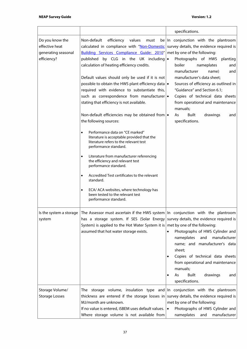
NEAP Survey Guide Version: 1.2
37
specifications.
Do you know the
effective heat
generating seasonal
efficiency?
Non-default efficiency values must be
calculated in compliance with “Non-Domestic
Building Services Compliance Guide: 2010”
published by CLG in the UK including
calculation of heating efficiency credits.
Default values should only be used if it is not
possible to obtain the HWS plant efficiency data
required with evidence to substantiate this,
such as correspondence from manufacturer
stating that efficiency is not available.
Non-default efficiencies may be obtained from
the following sources:
• Performance data on “CE marked”
literature is acceptable provided that the literature refers to the relevant test performance standard.
• Literature from manufacturer referencing the efficiency and relevant test performance standard.
• Accredited Test certificates to the relevant standard.
• ECA/ ACA websites, where technology has been tested to the relevant test performance standard.
In conjunction with the plantroom
survey details, the evidence required is
met by one of the following:
• Photographs of HWS plant(eg
boiler nameplates and
manufacturer name) and
manufacturer’s data sheet;
• Sources of efficiency as outlined in
“Guidance” and Section 6.1;
• Copies of technical data sheets
from operational and maintenance
manuals;
• As Built drawings and
specifications.
Is the system a storage
system
The Assessor must ascertain if the HWS system
has a storage system. If SES (Solar Energy
System) is applied to the Hot Water System it is
assumed that hot water storage exists.
In conjunction with the plantroom
survey details, the evidence required is
met by one of the following:
• Photographs of HWS Cylinder and
nameplates and manufacturer
name; and manufacturer’s data
sheet;
• Copies of technical data sheets
from operational and maintenance
manuals;
• As Built drawings and
specifications.
Storage Volume/
Storage Losses
The storage volume, insulation type and
thickness are entered if the storage losses in
MJ/month are unknown.
If no value is entered, iSBEM uses default values.
Where storage volume is not available from
In conjunction with the plantroom
survey details, the evidence required is
met by one of the following:
• Photographs of HWS Cylinder and
nameplates and manufacturer

NEAP Survey Guide Version: 1.2
38
other sources, and storage is accessible,
estimate storage volume by measuring the
dimensions of the storage vessel.
Refer to Appendix 9 of this Survey Guide for
guidance on determining the storage volume of
the storage unit.
The Assessor should use default values only if it
is not possible to obtain the HWS plant data or
measure volume on site, and should have
evidence to substantiate this.
Where storage insulation details are not
available from other sources, and insulation is
accessible, estimate insulation depth by
measuring its thickness (e.g. using a pin).
Default hot water cylinder insulation
thicknesses in Appendix A4.4 are used if
insulation is inaccessible.
name and manufacturer’s data
sheet;
• Copies of technical data sheets
from operational and maintenance
manuals;
• As Built drawings and
specifications.
Hot water storage volume measured on
site (and evidence of any calculations
retained by the Assessor)
Does the System have
Secondary Circulation
The Assessor must ascertain if the HWS system
has secondary circulation.
In conjunction with the plantroom
survey details, the evidence required is
met by one of the following:
• Photographs of secondary
pipework;
• Copies of technical data sheets
from operational and maintenance
manuals;
• As Built drawings and
specifications.
Circulation Losses/
Pump Power/ Loop
Length
If no value is entered, iSBEM uses default values
The Assessor should use default values only if it
is not possible to obtain the HWS plant details
and should have evidence to substantiate this.
In conjunction with the plantroom
survey details, the evidence required is
met by one of the following:
• Photographs of HWS pumps and
nameplates and manufacturer
name and manufacturer’s data
sheet;
• Copies of technical data sheets
from operational and maintenance
manuals;
• As Built drawings and
specifications.
Tick if there is Time
Control on Secondary
Circulation
The Assessor must ascertain if the HWS system
has time control on secondary circulation.
In conjunction with the plantroom
survey details, the evidence required is
met by one of the following:
• Photographs of secondary time
controls;

NEAP Survey Guide Version: 1.2
39
• Copies of technical data sheets
from operational and maintenance
manuals;
• As Built drawings and
specifications.
iSBEM Software Tab: “Building Services > SES”
Data Entry Item Guidance Documentary Evidence
In HWS Select from the HWS that the Solar Hot Water
Heating Applies.
In conjunction with the external survey
details, the evidence required is met by
one of the following:
• Copies of technical data sheets
from operational and Maintenance
Manuals;
• As Built drawings and
specifications.
Area Enter the aperture area of the solar collectors
The evidence required is met by one of
the following:
• Copies of technical data sheets
measured in accordance with EN
12975 or data from the HARP
database;
• Sources of efficiency as outlined in
Section 6.1;
• External survey data on Survey
Form with dimensions and
orientation and photographs of
solar collectors;
• As Built drawings and
specifications.
Orientation Select from the available options The evidence required is met by one of
the following:
• External survey data on Survey
Form with dimensions and
orientation and photographs of
solar collectors. Use a directional
compass;
• As Built drawings and
specifications.
Inclination Select from list of angles between 0O to 90O.
0O tilt represents a horizontal surface
90 O tilt represents a vertical surface
The evidence required is met by one of
the following:
• External survey data on Survey
Form with dimensions and
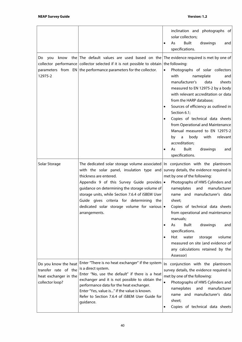
NEAP Survey Guide Version: 1.2
40
inclination and photographs of
solar collectors;
• As Built drawings and
specifications.
Do you know the
collector performance
parameters from EN
12975-2
The default values are used based on the
collector selected if it is not possible to obtain
the performance parameters for the collector.
The evidence required is met by one of
the following:
• Photographs of solar collectors
with nameplate and
manufacturer’s data sheets
measured to EN 12975-2 by a body
with relevant accreditation or data
from the HARP database;
• Sources of efficiency as outlined in
Section 6.1;
• Copies of technical data sheets
from Operational and Maintenance
Manual measured to EN 12975-2
by a body with relevant
accreditation;
• As Built drawings and
specifications.
Solar Storage The dedicated solar storage volume associated
with the solar panel, insulation type and
thickness are entered.
Appendix 9 of this Survey Guide provides
guidance on determining the storage volume of
storage units, while Section 7.6.4 of iSBEM User
Guide gives criteria for determining the
dedicated solar storage volume for various
arrangements.
In conjunction with the plantroom
survey details, the evidence required is
met by one of the following:
• Photographs of HWS Cylinders and
nameplates and manufacturer
name and manufacturer’s data
sheet;
• Copies of technical data sheets
from operational and maintenance
manuals;
• As Built drawings and
specifications.
• Hot water storage volume
measured on site (and evidence of
any calculations retained by the
Assessor)
Do you know the heat
transfer rate of the
heat exchanger in the
collector loop?
Enter “There is no heat exchanger” if the system is a direct system. Enter “No, use the default” if there is a heat exchanger and it is not possible to obtain the performance data for the heat exchanger. Enter “Yes, value is...” if the value is known. Refer to Section 7.6.4 of iSBEM User Guide for guidance.
In conjunction with the plantroom
survey details, the evidence required is
met by one of the following:
• Photographs of HWS Cylinders and
nameplates and manufacturer
name and manufacturer’s data
sheet;
• Copies of technical data sheets

NEAP Survey Guide Version: 1.2
41
from operational and maintenance
manuals;
• As Built drawings and
specifications.
Do you know the
overall heat loss
coefficient of all pipes
in the collector loop?
Enter “No, use the default” if it is not possible to obtain the performance data for the pipework in the collector loop. Enter “Yes, value is” if the value is known. Refer to Section 7.6.4 of iSBEM User Guide for guidance.
In conjunction with the plantroom
survey details, the evidence required is
met by one of the following along with
provision of representative
photographs of the pipework:
• Copies of technical data sheets
from operational and maintenance
manuals;
• As Built drawings and
specifications.
Are the distribution
pipes between the SES
and the back-up
system insulated?
This only becomes active if there is a separate solar cylinder to the HWS cylinder.
In conjunction with the plantroom
survey details, the evidence required is
met by one of the following:
• Photographs of pipework;
• As Built drawings and
specifications.
Auxiliary Energy
Consumption
Select from the circulation systems listed in the database.
In conjunction with the plantroom
survey details, the evidence required is
met by one of the following:
• Photographs of pumps and
nameplates and manufacturer
name and manufacturer’s data
sheet;
• Copies of technical data sheets
from operational and maintenance
manuals;
• As Built drawings and
specifications.
iSBEM Software Tab: “Building Services > PVS”
Data Entry Item Guidance Documentary Evidence
Type Select from the list of PV types. In conjunction with the plantroom
survey details, the evidence required is
met by one of the following:
• Photographs of PV panels and
nameplates and manufacturer
name and manufacturer’s data
sheet;
• Copies of technical data sheets

NEAP Survey Guide Version: 1.2
42
from operational and maintenance
manuals;
• As Built drawings and
specifications.
Area Enter the Area of the PV The evidence required is met by one of
the following:
• Photographs of Photovoltaics and
copies of technical data sheets
from manufacturer;
• Photographs of Photovoltaics and
External survey data on Survey
Form with dimensions and
orientation;
• As Built drawings and
specifications.
Orientation Select from one of the available options The evidence required is met by one of
the following:
• External survey data on Survey
Form with dimensions and
orientation with photographs of
PV. Use a directional compass;
• As Built drawings and
specifications.
Inclination Select from list of angles between 0O to 90O.
0O tilt represents a horizontal surface
90 O tilt represents a vertical surface
The evidence required is met by one of
the following:
• External survey data on Survey
Form with dimensions and
inclination and photographs of
PVs;
• As Built drawings and
specifications.
iSBEM Software Tab: “Building Services > Wind Generators”
Data Entry Item Guidance Documentary Evidence
Terrain Type Select from the list of Terrain types. In conjunction with the external survey
details, the evidence required is met by
one of the following:
• Photographs of surrounding sites;
• Site plan showing surrounding
sites.

NEAP Survey Guide Version: 1.2
43
Horizontal Axis -
Diameter
Enter the Diameter of the Wind Turbine The evidence required is met by one of
the following:
• Copies of technical data sheets
from manufacturer;
• External survey data on Survey
Form with dimensions and
photographs of wind turbines;
• As Built drawings and
specifications.
Others - Area Enter the Area Swept by the rotor blades. Refer
to Section 7.6.6 of the iSBEM Manual for details
The evidence required is met by one of
the following:
• Copies of technical data sheets
from manufacturer;
• External survey data on Survey
Form with dimensions and
photographs of wind turbines;
• As Built drawings and
specifications.
Height Enter the height by the wind turbine. Refer to
Section 7.6.6 of the iSBEM Manual for details.
The evidence required is met by one of
the following:
• Copies of technical data sheets
from manufacturer;
• External survey data on Survey
Form with dimensions and
photographs of wind turbines;
• As Built drawings and
specifications.
kW Enter the wind turbine rated power The evidence required is met by one of
the following:
• Copies of technical data sheets
from manufacturer and
photographs of wind turbines
nameplate;
• As Built drawings and
specifications.
iSBEM Software Tab: “Building Services > CHP generator”
Data Entry Item Guidance Documentary Evidence
Fuel Type Select from the Fuel Types In conjunction with the plantroom
survey details, the evidence required is
met by one of the following:
• Photographs of CHP nameplates
and manufacturer name and

NEAP Survey Guide Version: 1.2
44
manufacturer’s data sheets;
• Copies of technical data sheets
from operational and maintenance
manuals;
• As Built drawings and
specifications.
Heat Efficiency Seasonal thermal efficiency of the CHP
generator, defined as the total annual useful
heat supplied by the generator divided by the
total annual fuel energy input to the generator
(using the gross calorific value).
In conjunction with the plantroom
survey details, the evidence required is
met by one of the following:
• Photographs of CHP nameplates
and manufacturer name and
manufacturer’s data sheets in
compliance with the national
standards or the CHP EU directive
or EN 15316-4-4;
• Sources of efficiency as outlined in
Section 6.1;
• Copies of technical data sheets
from operational and maintenance
manuals;
• As Built drawings and
specifications.
Electrical Efficiency Total annual electric power output by the CHP
divided by the total annual fuel energy input
(using the gross calorific value).
In conjunction with the plantroom
survey details, the evidence required is
met by one of the following:
• Photographs of CHP nameplates
and manufacturer name and
manufacturer’s data sheets in
compliance with the national
standards or the CHP EU directive
or EN 15316-4-4;
• Sources of efficiency as outlined in
Section 6.1;
• Copies of technical data sheets
from operational and maintenance
manuals;
• As Built drawings and
specifications.
Building Space Heat
Supplied
Ascertain the proportion of space heating
supplied to the building by the CHP plant.
For existing buildings a report from the
Building Operator detailing the
proportion of space heating supplied
to the building by the CHP plant.
Where submetering of the heat is
unavailable, the report should be based
on actual fuel consumption converted

NEAP Survey Guide Version: 1.2
45
into heat consumption based on the
actual plant performances for a 12
month period.
For new buildings, a report signed by
engineers from the Design Team,
detailing the predicted proportion of
space heating supplied by the CHP
plant.
Building Hot Water
Supplied
Ascertain the proportion of hot water heating
supplied to the building by the CHP plant.
For existing buildings, a report from the
Building Operator detailing the
proportion of hot water supplied to the
building by the CHP plant.
Where submetering of the hot water is
unavailable, the report should be based
on actual fuel consumption converted
into hot water consumption based on
the actual plant performances for a 12
month period.
For new buildings, a report signed by
engineers from the Design Team,
detailing the predicted proportion of
hot water supplied by the CHP plant.
Tick this box for
Trigeneration systems
Ascertain if the building has a Trigeneration
system.
In conjunction with the plantroom
survey details, the evidence required is
met by one of the following:
• Photographs of CHP nameplates
and manufacturer name and
photographs of cooling System
(absorption chiller nameplate);
• Copies of technical data sheets
from operational and maintenance
manuals;
• As Built drawings and
specifications.
Building Cooling
Supplied
The Assessor must ascertain the proportion of
cooling supplied to the building by the
Trigeneration system
For existing buildings, a report from the
Building Operator detailing the
proportion of cooling supplied to the
building by the Trigeneration.
Where submetering of the chilled water
is unavailable, the report should be
based on running time for the plant
over a 12 month period and the actual
plant performances.
For new buildings, a report signed by
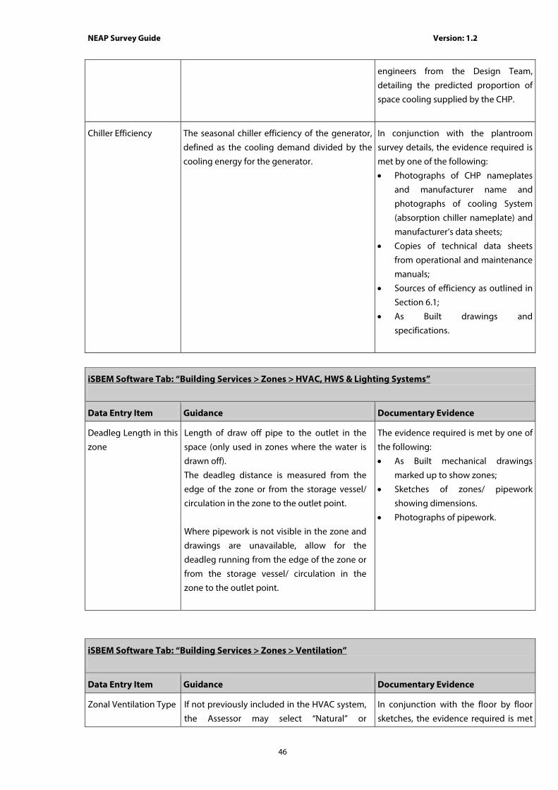
NEAP Survey Guide Version: 1.2
46
engineers from the Design Team,
detailing the predicted proportion of
space cooling supplied by the CHP.
Chiller Efficiency The seasonal chiller efficiency of the generator,
defined as the cooling demand divided by the
cooling energy for the generator.
In conjunction with the plantroom
survey details, the evidence required is
met by one of the following:
• Photographs of CHP nameplates
and manufacturer name and
photographs of cooling System
(absorption chiller nameplate) and
manufacturer’s data sheets;
• Copies of technical data sheets
from operational and maintenance
manuals;
• Sources of efficiency as outlined in
Section 6.1;
• As Built drawings and
specifications.
iSBEM Software Tab: “Building Services > Zones > HVAC, HWS & Lighting Systems”
Data Entry Item Guidance Documentary Evidence
Deadleg Length in this
zone
Length of draw off pipe to the outlet in the
space (only used in zones where the water is
drawn off).
The deadleg distance is measured from the
edge of the zone or from the storage vessel/
circulation in the zone to the outlet point.
Where pipework is not visible in the zone and
drawings are unavailable, allow for the
deadleg running from the edge of the zone or
from the storage vessel/ circulation in the
zone to the outlet point.
The evidence required is met by one of
the following:
• As Built mechanical drawings
marked up to show zones;
• Sketches of zones/ pipework
showing dimensions.
• Photographs of pipework.
iSBEM Software Tab: “Building Services > Zones > Ventilation”
Data Entry Item Guidance Documentary Evidence
Zonal Ventilation Type If not previously included in the HVAC system,
the Assessor may select “Natural” or
In conjunction with the floor by floor
sketches, the evidence required is met

NEAP Survey Guide Version: 1.2
47
“Mechanical Supply/Extract” to a zone. by one of the following:
• As Built mechanical drawings
marked up to show zones;
• Survey Form and photographs.
Do you know the
Supply/ Extract SFP?
There is an onus on the Assessor to make
reasonable efforts to find and use the fan
details and to resort to the default value only if
the information is not available.
Non-default values must be in compliance with
the “Non-Domestic Building Services
Compliance Guide: 2010” published by CLG in
the UK.
The evidence required is met by one
of the following:
• Photographs of fan nameplates
and manufacturer’s data sheets;
• Sources of efficiency as outlined in
Section 6.1;
• Copies of technical data sheets
from operational and maintenance
manuals;
• As Built drawings and
specifications.
Calculations of SFP must be retained
in all cases.
Does activity require
high pressure drop air
treatment
The Assessor must ascertain if high pressure
drop air treatment is required or alternatively
use the default based on selected activity.
If non-default values are used the
Assessor must obtain drawings and
specification showing high pressure
drop air treatment.
Ventilation Heat
Recovery
The heat recovery system may be
incorporated within the air handling unit(s) or
it may be external.
The Assessor must establish whether or not
heat recovery is fitted and to make reasonable
efforts to ascertain its seasonal efficiency.
The default value should be used for efficiency
if there is no documentary evidence to
substantiate non-default entries.
A non-default value should be used where
possible.
Non-default values should be in compliance
with Section 10.5 of “Non-Domestic Building
Services Compliance Guide: 2010” published by
CLG in the UK
In conjunction with the plantroom
survey details, the evidence required is
met by one of the following:
• Photographs of heat recovery
unit and manufacturer’s data
sheets;
• Sources of efficiency as outlined in
Section 6.1;
• Copies of technical data sheets
from operational and
maintenance manuals;
• As Built drawings and
specifications.
iSBEM Software Tab: “Building Services > Zones > Exhaust”
Data Entry Item Guidance Documentary Evidence

NEAP Survey Guide Version: 1.2
48
Is there local
mechanical exhaust in
the zone
The Assessor must ascertain if there is
mechanical exhaust from a zone
In conjunction with the floor by floor
sketches, the evidence required is met
by one of the following:
• As Built mechanical drawings
marked up to show zones;
• Survey Form and photographs.
Local Mechanical
Exhaust
The Assessor must determine the l/s/m2 floor
area.
Default values can be obtained from CIBSE
Guide F Part A.
In conjunction with the floor by floor
sketches, the evidence required is met
by one of the following:
• As Built mechanical drawings
marked up to show zones;
• Photos of fan nameplates showing
Model number and Flow rate;
• Survey Form and photographs.
Do you know the
Supply/ Extract SFP?
Assessors must make reasonable efforts to
find and use the fan details and to resort to
the default value only if the information is not
available.
Non-default values should be in compliance
with Section 10.5 of “Non-Domestic Building
Services Compliance Guide: 2010” published by
CLG in the UK
The evidence required is met by one
of the following:
• Photographs of fan nameplates
and manufacturer’s data sheets;
• Sources of efficiency as outlined in
Section 6.1;
• Copies of technical data sheets
from operational and maintenance
manuals;
• As Built drawings and
specifications.
Calculations of SFP must be retained
in all cases.
iSBEM Software Tab: “Building Services > Zones > Lighting”
Data Entry Item Guidance Documentary Evidence
What information is
available on Lighting
The default value of lighting parameters not
available is selected when there is no
documentary evidence to substantiate the Full
Lighting Design Carried out entry.
In order to use the Full Lighting
Design Carried Out entry the Assessor
must have a signed statement from a
partner/director of the consultants
(normally the M&E engineers)
responsible for the lighting design
showing the installed power and
design illuminance for each of the
zones.
Lighting Parameters
not available
Determine the lamp type for each zone.
Where the specific fitting cannot be identified,
take the most conservative (highest power
density) option from Table 15 of the iSBEM
In conjunction with the floor by floor
sketches, the evidence required is met
by one of the following:
• As Built Electrical Lighting

NEAP Survey Guide Version: 1.2
49
User Guide.
Refer to Appendix 11 for guidance on
selection of lamp type.
Refer to Appendix 4 for the details on how Shell
and Core buildings are dealt with.
Where LED lighting is present and Lighting
Parameters are not available, refer to section
A4.10 of the NEAP Survey Guide.
Where a combination of lighting systems is
present in the zone providing general lighting
(no display lighting), the zone should be split to
reflect the lamp locations.
Where a combination of lighting systems is
present in the zone providing general lighting
(no display lighting) across the entire zone, such
that splitting the zone to reflect the lamps
location is not practicable (For example the
zone contains a combination of fluorescents
and down lighters mixed throughout the zone)
then the following method is used:
• The proportion of the zone’s area lit by each
lamp type is established.
• The zone is split into a number of zones to
match the number of lamp types and for
each lamp type the relevant proportion of
the zone area and all of the zone’s
envelopes, including glazing should be
entered into each relevant zone along with
the appropriate respective lamp type.
Drawings marked up to show
zones;
• Survey Form and photographs of
light fittings. Photograph(s) of each
light type should be provided.
Are air extracting
luminaires fitted
The Assessor must determine if air extracting
luminaires are fitted.
In conjunction with the floor by floor
sketches, the evidence required is met
by one of the following:
• As Built Electrical Lighting
Drawings marked up to show
zones;
• Survey Form and photographs of
light fittings.
iSBEM Software Tab: “Building Services > Zones > Lighting Controls”
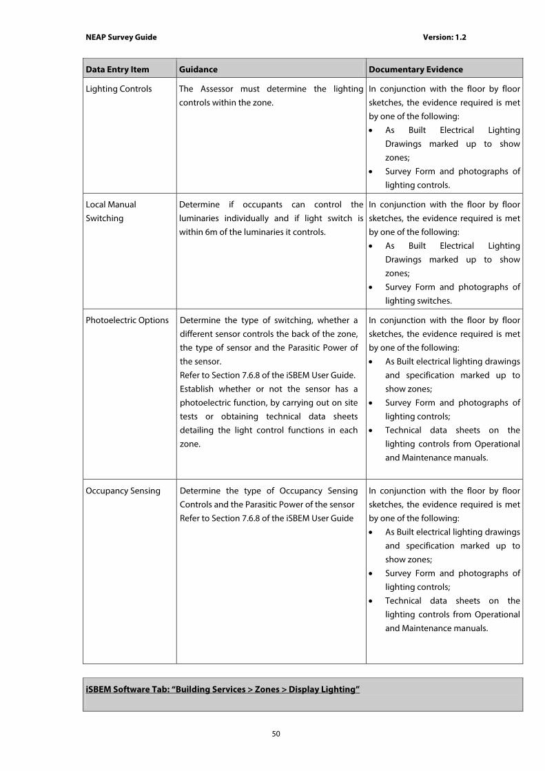
NEAP Survey Guide Version: 1.2
50
Data Entry Item Guidance Documentary Evidence
Lighting Controls The Assessor must determine the lighting
controls within the zone.
In conjunction with the floor by floor
sketches, the evidence required is met
by one of the following:
• As Built Electrical Lighting
Drawings marked up to show
zones;
• Survey Form and photographs of
lighting controls.
Local Manual
Switching
Determine if occupants can control the
luminaries individually and if light switch is
within 6m of the luminaries it controls.
In conjunction with the floor by floor
sketches, the evidence required is met
by one of the following:
• As Built Electrical Lighting
Drawings marked up to show
zones;
• Survey Form and photographs of
lighting switches.
Photoelectric Options Determine the type of switching, whether a
different sensor controls the back of the zone,
the type of sensor and the Parasitic Power of
the sensor.
Refer to Section 7.6.8 of the iSBEM User Guide.
Establish whether or not the sensor has a
photoelectric function, by carrying out on site
tests or obtaining technical data sheets
detailing the light control functions in each
zone.
In conjunction with the floor by floor
sketches, the evidence required is met
by one of the following:
• As Built electrical lighting drawings
and specification marked up to
show zones;
• Survey Form and photographs of
lighting controls;
• Technical data sheets on the
lighting controls from Operational
and Maintenance manuals.
Occupancy Sensing Determine the type of Occupancy Sensing
Controls and the Parasitic Power of the sensor
Refer to Section 7.6.8 of the iSBEM User Guide
In conjunction with the floor by floor
sketches, the evidence required is met
by one of the following:
• As Built electrical lighting drawings
and specification marked up to
show zones;
• Survey Form and photographs of
lighting controls;
• Technical data sheets on the
lighting controls from Operational
and Maintenance manuals.
iSBEM Software Tab: “Building Services > Zones > Display Lighting”

NEAP Survey Guide Version: 1.2
51
Data Entry Item Guidance Documentary Evidence
Refer to Section 7.6.8
of the iSBEM User
Guide
This is the lighting intended to highlight displays of exhibits or merchandise, or lighting used in spaces for public leisure and entertainment such as dance halls, auditoria, conference halls, restaurants and cinemas. Refer to Section A4.11 Display Lighting where zones incorporate an activity where SBEM automatically assumes the presence of display lighting but none is actually present.
In conjunction with the floor by floor
sketches, the evidence required is met
by one of the following:
• As Built electrical lighting drawings
and specification marked up to
show zones;
• Survey Form and photographs of
lighting controls;
• Technical data sheets on the
lighting controls from the
operational and maintenance
manuals.
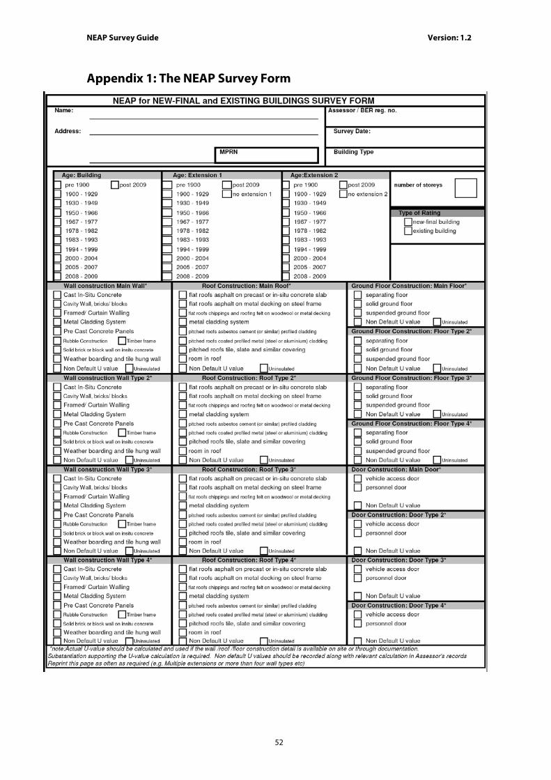
NEAP Survey Guide Version: 1.2
52
Appendix 1: The NEAP Survey Form

NEAP Survey Guide Version: 1.2
53

NEAP Survey Guide Version: 1.2
54

NEAP Survey Guide Version: 1.2
55

NEAP Survey Guide Version: 1.2
56

NEAP Survey Guide Version: 1.2
57

NEAP Survey Guide Version: 1.2
58
Appendix 2: Zoning Example Assessors must adhere to the zoning convention as set out in section 3.3 of the iSBEM User Guide which may help reduce the amount of time and measurement required. The following is an example office building:
Zoning the building by using the convention set out in the iSBEM user guide can help reduce the number of measurements that need to be taken. The office building can be zoned as follows:

NEAP Survey Guide Version: 1.2
59
It is important to note that internal envelopes between merged zones with thermal mass must be included within the model. The km values determine how the building retains and emits heat, and hence they must be defined in iSBEM. You can sum the areas of two or more internal walls (between merged zones) with the same construction, adjoining condition and orientation and enter them as one envelope (assigned to the zone resulting from the merging). If the internal walls are partitions of light construction and very small thermal mass, then they should not cause any significant effects on the calculation.

NEAP Survey Guide Version: 1.2
60
Appendix 3: List of Activities
Building Types/Activities Offi
ce
prim
ary
scho
ols
seco
ndar
y sc
hool
furth
er e
duca
tion
univ
ersi
ties
prim
ary
heal
th c
are
build
ings
nurs
ing,
resi
dent
ial h
omes
and
hos
tels
hosp
ital
hote
l
rest
aura
nt/b
ar/p
ublic
hou
se
spor
ts c
entre
/leis
ure
cent
re
spor
ts g
roun
d/ar
ena
reta
il
war
ehou
se a
nd s
tora
ge
thea
tres/
cine
mas
/ mus
ic h
alls
and
aud
itoria
soci
al c
lubs
com
mun
ity/d
ay c
entre
libra
ries,
mus
eum
s an
d ga
llerie
s
pris
ons
emer
genc
y se
rvic
es
crow
n an
d co
unty
cou
rts
airp
ort t
erm
inal
s
stat
ion/
train
sta
tion/
seap
ort t
erm
inal
wor
ksho
ps/m
aint
enan
ce d
epot
tele
phon
e ex
chan
ges
Indu
stria
l pro
cess
bui
ldin
g
Laun
dry
Dw
ellin
g
Ret
ail W
areh
ouse
Mis
cella
neou
s 24
hr a
ctiv
ities
Cellular office X X X X X X X X X X X X X X X X X X X X X X X X X X
Open plan office X X X X X X X X X X X X X X X X X X X X X X X X X X
Storage area X X X X X X X X X X X X X X X X X X X X X X X X X X X
Circulation (corridors and stairs) (- non public) X X X X X X X X X X X X X X X X X X X X X X X X X X
Toilets X X X X X X X X X X X X X X X X X X X X X X X X X X
Tea making X X X X X X X X X X X X X X X X X X X X X X X X X X
Reception X X X X X X X X X X X X X X X X X X X X X
Meeting room X X X X X X X X X X X X X X X X X X X X X
Dry sports hall X X X X X X X X X X X
Changing facilities X X X X X X X X X X X X X X X
Swimming pool X X X X X

NEAP Survey Guide Version: 1.2
61
Food preparation area X X X X X X X X X X X X X X X X X X X X X
Hall/lecture theatre/assembly area X X X X X X X X X X X X
Laboratory X X X X X
Waiting room X X X X X X X
Consulting room X X X X X
Operating theatre X
Patient accomodation (wards) X
Bathroom X X X X X X
Bedroom X X X X
Eating/drinking area X X X X X X X X X X X X X X X X X X X X X X
Sales area - general X X X X
Sales area -chilled X X
Storage - chilled X X X X X X X
Display area X X X X X X X
Performance area (stage) X X X X
Plant room X X X X X X X X X X X X X X X X X X X X X X X X X X
Workshop - small scale X X X X X X X X X X X X X X
Industrial process area X X
Cell (police/prison) X X X
High density IT work space X X X X X X
IT equipment X X X X X X X X X
Laundry X X X X X X X
Common room/staff room/lounge X X X X X X X X X X X X X X X X X X X X
Security check area X

NEAP Survey Guide Version: 1.2
62
Baggage reclaim area X
Check-in area X
Circulation (public areas) X X X X X X
Warehouse storage X X X
Warehouse storage - chilled X X X
Domestic lounge X
Domestic kitchen X
Domestic toilets X
Domestic dining room X
Domestic bathroom X
Domestic bedroom X
Domestic circulation X
Warehouse sales - general X
Warehouse sales - chilled X
Warehouse sales - electrical X
Fitness suite/gym X X X X X X X
Fitness studio X X
Sales area - electrical X
Ice rink X
Classroom X X X X
Hydrotherapy Pool X
Storage area - cold room (<0oC) X X X X X X X X
Intensive care/high dependency X
Diagnostic Imaging X
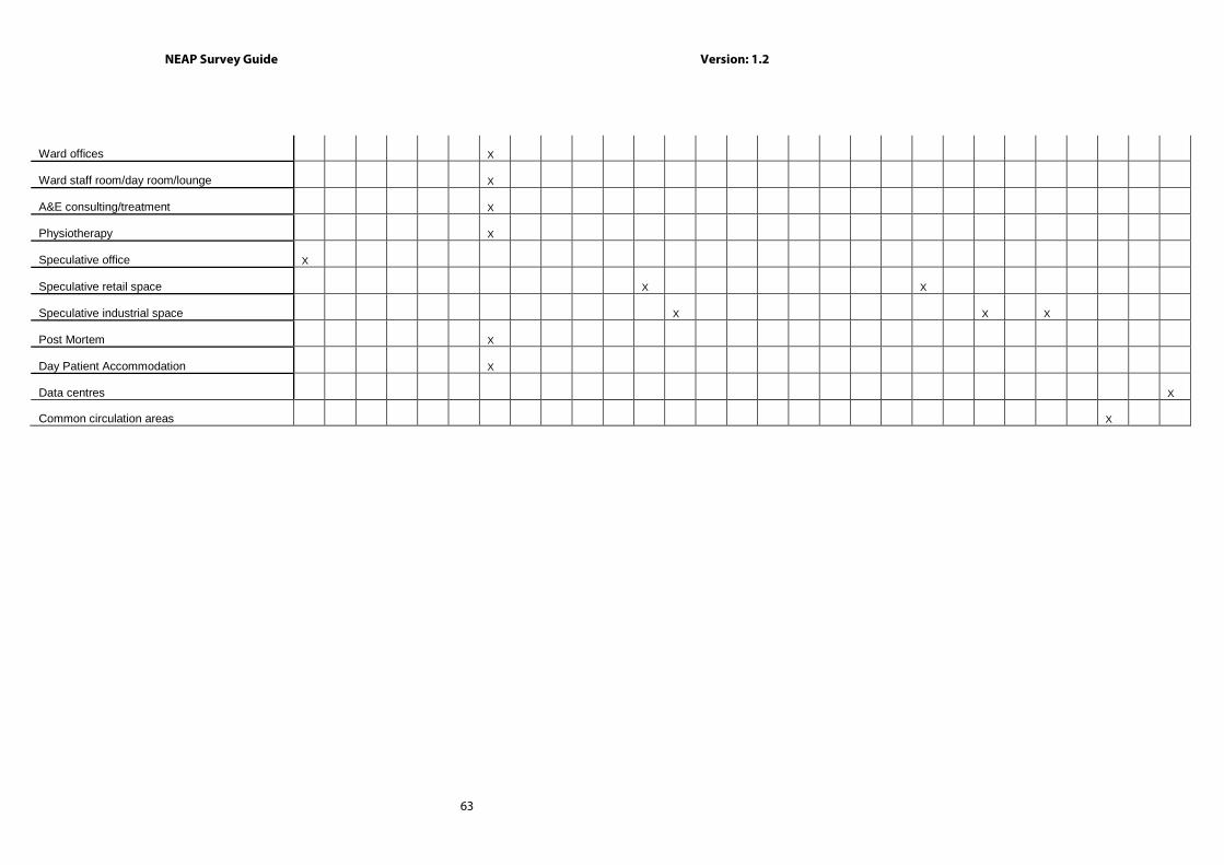
NEAP Survey Guide Version: 1.2
63
Ward offices X
Ward staff room/day room/lounge X
A&E consulting/treatment X
Physiotherapy X
Speculative office X
Speculative retail space X X
Speculative industrial space X X X
Post Mortem X
Day Patient Accommodation X
Data centres X
Common circulation areas X
NEAP Survey Guide Version: 1.2
64
Appendix 4: Default Data This section outlines defaults to be used for non-domestic BERs in the absence of evidence supporting non-default data. Actual data must be used where acceptable evidence is available.
A4.1 Age of Building The Age of Building/ Year of Construction is used to identify the appropriate default U-values for construction elements based on the relevant building regulations. Note on use of defaults: 1) Buildings constructed prior to the introduction of Building Regulations in 1992 were not required to have
insulation; therefore the Assessor must demonstrate that insulation is present when selecting “Pre 1991”
options for external elements. “Pre 1991” assumes a certain amount of insulation is present. If unable to
demonstrate that insulation is present in “Pre 1991” buildings, “No date – Uninsulated” must be used for
external elements from “Help with Inference procedures”.
2) Buildings constructed after the introduction of Building Regulations in 1992 were required to have
insulation, therefore select relevant building regulations for external elements from “Help with Inference
procedures”, except where the element is known to be uninsulated. In this case, select “No date –
Uninsulated” from “Help with Inference procedures”.
3) For internal elements, irrespective of the adjoining condition, select “No date – Uninsulated” irrespective of
the age of the building, unless able to demonstrate that insulation is present. In this case, calculate the U-
value by adding the insulation resistance to the default U value for the element without insulation. The
internal element U-value is adjusted as per Appendix 8 if adjoining an unconditioned space.
In all cases, the U-value can be calculated using full details of all the layers (where thicknesses and thermal
properties are known).
iSBEM Software Tab: “Project Database ”
Year of Construction Relevant Building Regulations and selecting defaults.
Pre 1994 (external elements)
“No date – Uninsulated” –is selected unless the element is proven to be insulated.
Pre 1991 –where element is proven to be insulated.
1994 to 1999 (external elements)
1992 Building Regulations or,
“No date – Uninsulated” – where element is known to be uninsulated.
2000 to 2004 (external elements)
1997 Building Regulations or,
“No date – Uninsulated” – where element is known to be uninsulated.
2005 to 2007 (external elements)
2002 Building Regulations or,
“No date – Uninsulated” – where element is known to be uninsulated.
2008 to 2009 (external elements)
2006 Building Regulations or,
“No date – Uninsulated” – where element is known to be uninsulated.

NEAP Survey Guide Version: 1.2
65
Post 2009 (external elements)
2007 Building Regulations or,
“No date – Uninsulated” – where element is known to be uninsulated.
Internal Elements “No date – Uninsulated” – unless proven to be insulated.
A4.2 Constructional Types The Help with Inference procedures is the main source of default data for external elements, the Library
database may be used if it is more representative of the construction.
iSBEM Software Tab: “Project Database”
Data Entry Item Default Value Construction for Floors
Select from “Help with Inference procedures” within iSBEM software.
If known to be uninsulated, internal or constructed pre 1994, select “uninsulated” option.
“Import one from the library” may be used where the detail in the library database is more
representative of the construction than that given in the inference procedure.
For Internal Floors/ Ceiling select from “Import one from the library” as the database is more
representative of the construction.
Construction for Walls Construction for Roofs
Construction for Doors
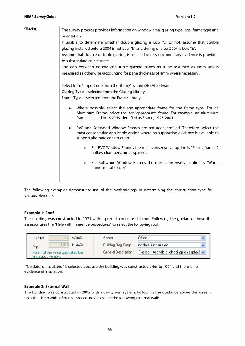
NEAP Survey Guide Version: 1.2
66
Glazing
The survey process provides information on window area, glazing type, age, frame type and
orientation.
If unable to determine whether double glazing is Low “E” or not, assume that double
glazing installed before 2004 is not Low “E” and during or after 2004 is Low “E”.
Assume that double or triple glazing is air filled unless documentary evidence is provided
to substantiate an alternate.
The gap between double and triple glazing panes must be assumed as 6mm unless
measured as otherwise (accounting for pane thickness of 4mm where necessary).
Select from “Import one from the library” within iSBEM software.
Glazing Type is selected from the Glazing Library
Frame Type is selected from the Frame Library:
• Where possible, select the age appropriate frame for the frame type. For an Aluminum Frame, select the age appropriate frame. For example, an aluminum frame installed in 1999, is identified as Frame, 1995-2001.
• PVC and Softwood Window Frames are not aged profiled. Therefore, select the
most conservative applicable option where no supporting evidence is available to support alternate construction.
o For PVC Window Frames the most conservative option is “Plastic frame, 2
hollow chambers, metal spacer”.
o For Softwood Window Frames the most conservative option is “Wood frame, metal spacer”
The following examples demonstrate use of the methodology in determining the construction type for various elements: Example 1: Roof The building was constructed in 1975 with a precast concrete flat roof. Following the guidance above the assessor uses the “Help with Inference procedures” to select the following roof:
“No date, uninsulated” is selected because the building was constructed prior to 1994 and there is no evidence of insulation. Example 2: External Wall The building was constructed in 2002 with a cavity wall system. Following the guidance above the assessor uses the “Help with Inference procedures” to select the following external wall:

NEAP Survey Guide Version: 1.2
67
“Republic of Ireland (1997)” is the relevant building regulation as per the above table. This is selected because the building was constructed post the introduction of building regulations and is therefore assumed to have insulation. Example 3: Solid Brick Internal Wall The building was constructed in 2010. The internal walls were constructed of 215mm solid bricks. Following the guidance above the assessor uses the “Help with Inference procedures” to select the following wall:
“No date, uninsulated” is selected as the wall is an internal element. It is assumed that no insulation is present unless the Assessor can demonstrate otherwise. Example 4: Internal Stud Partition The building was constructed in 1995. The internal walls were constructed of a stud partition. Following the guidance above the assessor uses the “Help with Inference procedures” to select the following wall:
“No date, uninsulated” is selected as the wall is an internal element. It is assumed that no insulation is present unless the assessor can demonstrate otherwise. Note: The default U value for lightweight partition walls in iSBEM has a very low U value and does not represent an uninsulated stud partition wall and therefore should not be used unless the assessor can demonstrate that insulation is present.
Example 5: Vehicle Access Door The building was constructed in 2005. Following the guidance above the assessor uses the “Help with Inference procedures” to select the following door:
“Republic of Ireland (2002)” is the relevant building regulation as per the above table. This is selected because the building was constructed post the introduction of building regulations and is therefore assumed to have insulation.

NEAP Survey Guide Version: 1.2
68
A4.3 HVAC System Defaults In some zones, a default HVAC system must be specified. Further Guidance is given in Appendix 7 through the use of flow charts in helping identify the use of default HVAC systems. Default HVAC systems are applied to zones meeting the following criteria:
• There is no fixed heating installed; • There are floor and ceiling finishes, lighting, and ventilation as appropriate; • The Activity Type requires conditioning; • There is no proposal to fit out the zone with services in the future; • Not considered transient, indirectly heated spaces or spaces heated by a process load.
Section 7.5.3 of the iSBEM user guide states “If a zone is defined as having no heating or cooling, i.e., assigned to ‘Zones without HVAC system’, but the activity type selected for the zone is one which typically requires conditioning (according to the Activity Database), a red exclamation mark “!”appears next to this parameter as a warning to the user, in case this was done in error.“ When assuming a default HVAC system following the guidance above and Appendix 7, use the following table: iSBEM Software Tab: “HVAC”
Data Entry Item Default Value No evidence of a HVAC present
The default HVAC systems for buildings are as follows:
1. 'Heating only - Electric resistance’ - Assumed to be electric central heating system
with warm air distribution. If you do not know the heating method you should select electric resistance heating as your default. Selected when no non-electrical
fuels are present.
2. “Heating only - Other systems’ - Assumed to be wet radiator system, heat generated
by fuel combustion. This is applied where the building also has a fuel source other
than electricity installed.
3. ‘Heating and mechanical cooling’ - Assumed to be constant volume air system with
terminal reheat and fixed fresh air. This is the assumed HVAC system in the absence
of other information for conditioned spaces.
4. If no HVAC system serves a zone (ie an unconditioned zone in SBEM) select “Zone
without HVAC system”. This is only in the case where it has been justified that a HVAC system is not required in the zone in the NEAP assessment.
For details Refer to 7.5.3 of the iSBEM User Guide.
The following table outlines examples of when various default HVAC systems apply following the guidance above:

NEAP Survey Guide Version: 1.2
69
Default HVAC System
Building Condition Zone Conditions
Heating only -
Electric resistance
No alternate (e.g. gas/oil)
fuel present in the building.
Electricity may or may not
be connected to the
building.
• Zone Activity requires heating (as highlighted by the red
exclamation mark in SBEM), for example: Offices, Meeting Rooms, Laboratory, Consulting Room, Sales Area, Performance Area, Classroom Does not include unheated transient, indirectly heated
spaces or spaces heated by a process load.
• While the zone activity requires heating, the zone is also
capable of being naturally ventilated and therefore
there is no requirement for cooling. The zone also lends
itself to meeting CIBSE Guide A and the Building
Regulations for naturally ventilated spaces. The CIBSE
Guide A Section 1.4.2.5 and Building Regulation requires
that in the absence of mechanical cooling or mechanical
ventilation, the space temperature will not exceed 280C
for an unacceptable proportion of the period of
occupation. The zone would be expected to achieve
adequate natural ventilation following Building
Regulation/ CIBSE requirements under the following
circumstances:
• Internal load is not excessive, and
• Space can be naturally ventilated for example:
• Zones not deeper than 7m for single side
ventilation and 14m for cross ventilation
• Sufficient natural ventilation openings e.g.
openable windows, doors (approximately 5%
of floor area)

NEAP Survey Guide Version: 1.2
70
Default HVAC System
Building Condition Zone Conditions
Heating only -
Other systems
Alternate fuel present in the
building, for example:
• Natural Gas pipework
connected to building,
whether meter evident
or not. • Oil Tank Present and
connected to building • LPG Tank Present and
connected to building • Solid Fuel Store Present
appropriate size to
heat building.
• Zone Activity requires heating (as highlighted by the red
exclamation mark in SBEM, for example:
Offices, Meeting Rooms, Laboratory, Consulting Room, Sales Area, Performance Area, Classroom Does not include unheated transient, indirectly heated
spaces or spaces heated by a process load.
• While the zone activity requires heating, the zone is also
capable of being naturally ventilated and therefore
there is no requirement for cooling. The zone also lends itself to meeting CIBSE Guide A and
the Building Regulations for naturally ventilated spaces.
The CIBSE Guide A Section 1.4.2.5 and Building
Regulation require that in the absence of mechanical
cooling or mechanical ventilation, the space
temperature will not exceed 280C for an unacceptable
proportion of the period of occupation. The zone would
be expected to achieve adequate natural ventilation
following the Building Regulation/ CIBSE requirements
under the following circumstances: • Internal load is not excessive, and
• Space can be naturally ventilated for example:
• Zones not deeper than 7m for single side
ventilation and 14m for cross ventilation
• Sufficient natural ventilation openings e.g.
openable windows, doors (approximately 5%
of floor area)

NEAP Survey Guide Version: 1.2
71
Default HVAC System
Building Condition Zone Conditions
Heating and
mechanical
cooling
Alternate fuel present in the building and where cooling
is required, for example:
• Natural Gas pipework
connected to building,
whether meter evident
or not. • Oil Tank Present and
connected to building • LPG Tank Present and
connected to building • Solid Fuel Store Present
appropriate size to
heat building. Where no alternate fuel is
present in the building but
it is proven that cooling is
required, “Natural Gas” is
selected as the heating fuel.
Currently electricity is not
available as a heating fuel
for the default system,
“Natural Gas” is selected as
it is the heating fuel used in
the notional building.
• Zone Activity requires climate control during summer
and it is not possible to naturally ventilate, for example:
Offices, Meeting Rooms, Laboratory, Consulting Room, Sales Area, Performance Area, Classroom Does not include unheated transient, indirectly heated
spaces or spaces heated by a process load.
Transient zones Some unheated zones have a transient/ passing occupancy such as toilets, changing facilities or tea making facilities. For transient zones, where “Zones without HVAC system” is selected, it is acceptable for the red exclamation mark”!” to appear. There are further details on transient spaces in the SBEM Technical Manual table “List of Activity areas with definitions” and Table A7.2 of this survey guide. Indirectly conditioned zones As outlined in section 7.6.8 of the iSBEM user guide, zones “which are not serviced by a HVAC system, i.e. have no direct supply of heating or cooling, but are likely to be indirectly conditioned by the surrounding areas due to the high level of interaction with those spaces (allowing the heated air to move freely from the directly conditioned spaces to the indirectly conditioned ones), they must be considered heated or conditioned (indirectly) by the same HVAC system that supplies the most important surrounding area”. An unconditioned enclosed zone is not considered as “indirectly conditioned” as air cannot move freely from a directly conditioned zone to the unconditioned zone. See Table A7.2.
NEAP Survey Guide Version: 1.2
72
A4.4 HWS System
iSBEM Software Tab: “HWS”
Data Entry Item Default Value No evidence of a Hot Water System present
Where a fuel (oil/gas) is supplied to the building, the HWS System:
“Dedicated Hot Water Boiler” should be selected with a fuel type based on fuel supplied
to unit.
Where no fuel is supplied to the building, the HWS System:
“Instantaneous Hot Water only” should be selected with a fuel type of “Grid Supplied
Electricity”
HWS System Storage/ Secondary Circulation Losses: Not present
The iSBEM User Guide Section 7.6.8 states that “Depending on the activity and building
type selected for the zone, a standard hot water demand is assumed. For example, there
is a demand assumed to arise from the occupants of an office for activities such as
washing hands and washing up cups. This demand is associated with the office rather
than the toilet or tea room.” Hot Water Storage system insulation if not accessible
The insulation thickness is based on the age of the storage unit as below: If the age of the storage unit is unknown, it must be assumed that the storage unit is the same age as the building.
Pre 1993: No Insulation
1994 to 1999: 25mm Factory Insulated
Post 1999: 35mm Factory Insulated
A4.5 SES System
iSBEM Software Tab: “SES”
Data Entry Item Default Value Evidence of solar collector present but data unobtainable
If present, the parameters for the calculation are as follows for each unobtainable item: - panel aperture area 3 m² ; - flat panel, glazed; - facing South, pitch 30°; - combined cylinder, solar part one-third of total, or if a combi boiler the cylinder identified is a dedicated solar cylinder. If combined cylinder is accessible, solar storage volume is portion below the coil directly above the solar heated coil.
Gross Area obtained from survey
Aperture Area= Flat Plate Glazed Gross Area x 0.9 Aperture Area= Evacuated Tube Gross Area x 0.72
A4.6 PV System
iSBEM Software Tab: “PVS”
Data Entry Item Default Value Evidence of PV present but data unobtainable
If present, the parameters for the calculation are as follows for each unobtainable item: - PV area is roof area for heat loss, times percent of roof area covered by PVs, and if pitched roof divided by cos(35°) ; - Type: Amorphous silicon; - facing South, pitch 30°.
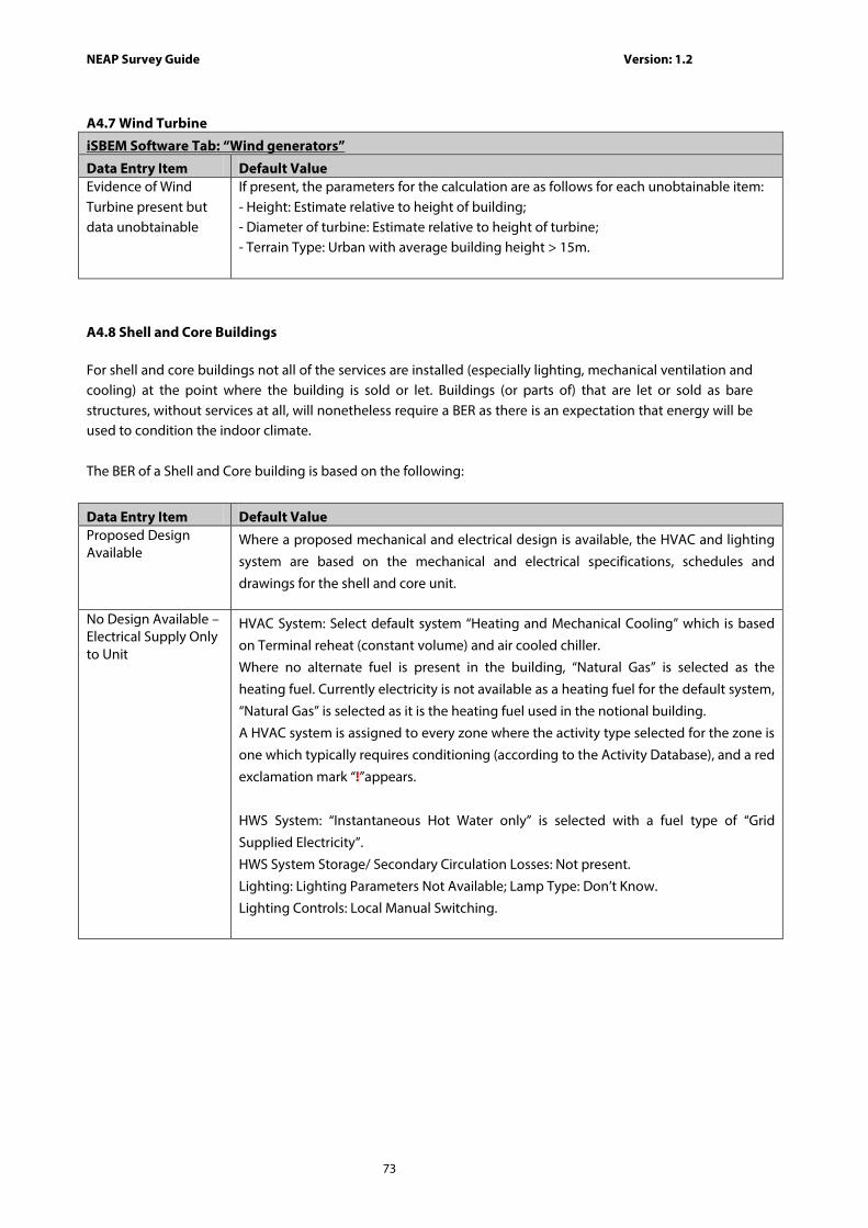
NEAP Survey Guide Version: 1.2
73
A4.7 Wind Turbine
iSBEM Software Tab: “Wind generators”
Data Entry Item Default Value Evidence of Wind Turbine present but data unobtainable
If present, the parameters for the calculation are as follows for each unobtainable item: - Height: Estimate relative to height of building; - Diameter of turbine: Estimate relative to height of turbine; - Terrain Type: Urban with average building height > 15m.
A4.8 Shell and Core Buildings
For shell and core buildings not all of the services are installed (especially lighting, mechanical ventilation and cooling) at the point where the building is sold or let. Buildings (or parts of) that are let or sold as bare structures, without services at all, will nonetheless require a BER as there is an expectation that energy will be used to condition the indoor climate.
The BER of a Shell and Core building is based on the following:
Data Entry Item Default Value Proposed Design Available
Where a proposed mechanical and electrical design is available, the HVAC and lighting
system are based on the mechanical and electrical specifications, schedules and
drawings for the shell and core unit.
No Design Available – Electrical Supply Only to Unit
HVAC System: Select default system “Heating and Mechanical Cooling” which is based
on Terminal reheat (constant volume) and air cooled chiller.
Where no alternate fuel is present in the building, “Natural Gas” is selected as the
heating fuel. Currently electricity is not available as a heating fuel for the default system,
“Natural Gas” is selected as it is the heating fuel used in the notional building.
A HVAC system is assigned to every zone where the activity type selected for the zone is
one which typically requires conditioning (according to the Activity Database), and a red
exclamation mark “!”appears.
HWS System: “Instantaneous Hot Water only” is selected with a fuel type of “Grid
Supplied Electricity”.
HWS System Storage/ Secondary Circulation Losses: Not present.
Lighting: Lighting Parameters Not Available; Lamp Type: Don’t Know.
Lighting Controls: Local Manual Switching.
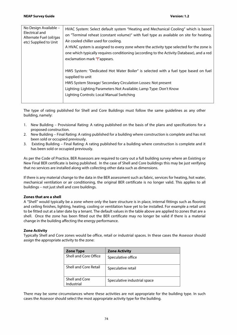
NEAP Survey Guide Version: 1.2
74
No Design Available – Electrical and Alternate Fuel (oil/gas etc) Supplied to Unit
HVAC System: Select default system “Heating and Mechanical Cooling” which is based
on ”Terminal reheat (constant volume)“ with fuel type as available on site for heating.
Air cooled chiller used for cooling.
A HVAC system is assigned to every zone where the activity type selected for the zone is
one which typically requires conditioning (according to the Activity Database), and a red
exclamation mark “!”appears.
HWS System: “Dedicated Hot Water Boiler” is selected with a fuel type based on fuel
supplied to unit
HWS System Storage/ Secondary Circulation Losses: Not present
Lighting: Lighting Parameters Not Available; Lamp Type: Don’t Know
Lighting Controls: Local Manual Switching
The type of rating published for Shell and Core Buildings must follow the same guidelines as any other building, namely: 1. New Building – Provisional Rating: A rating published on the basis of the plans and specifications for a
proposed construction. 2. New Building – Final Rating: A rating published for a building where construction is complete and has not
been sold or occupied previously. 3. Existing Building – Final Rating: A rating published for a building where construction is complete and it
has been sold or occupied previously. As per the Code of Practice, BER Assessors are required to carry out a full building survey where an Existing or New Final BER certificate is being published. In the case of Shell and Core buildings this may be just verifying that no services are installed along with collecting other data such as dimensions. If there is any material change to the data in the BER assessment such as fabric, services for heating, hot water, mechanical ventilation or air conditioning, the original BER certificate is no longer valid. This applies to all buildings – not just shell and core buildings. Zones that are a shell A “Shell” would typically be a zone where only the bare structure is in place, internal fittings such as flooring and ceiling finishes, lighting, heating, cooling or ventilation have yet to be installed. For example a retail unit to be fitted out at a later date by a tenant. The default values in the table above are applied to zones that are a shell. Once the zone has been fitted out the BER certificate may no longer be valid if there is a material change in the building affecting the energy performance. Zone Activity Typically Shell and Core zones would be office, retail or industrial spaces. In these cases the Assessor should assign the appropriate activity to the zone:
Zone Type Zone Activity Shell and Core Office
Speculative office
Shell and Core Retail
Speculative retail
Shell and Core Industrial
Speculative industrial space
There may be some circumstances where these activities are not appropriate for the building type. In such cases the Assessor should select the most appropriate activity type for the building.

NEAP Survey Guide Version: 1.2
75
A4.9 Unheated Buildings
A BER assessment is not required for the following unheated building types:
• an industrial building not intended for human occupancy over extended periods and where the installed heating capacity does not exceed 10 W/m2; or
• a non-residential agricultural building where the installed heating capacity does not exceed 10 W/m2
However if the building is unheated and does not comply with the above guidelines, a BER assessment is required. Further Guidance is given in Appendix 7 through the use of flow charts and matrices in helping identify the application of unheated building or zones. One such example would be a building with no installed HVAC due to high internal or process loads. iSBEM must have a heating system applied to a zone in the building in order for the software to operate.
When carrying out a BER on an unheated building, base the heating system on the notional building’s heating system and apply it to all zones within the building. For the purpose of this guide, an unheated building is defined as a building that has been fitted out with other services such as lighting, hot water, mechanical ventilation etc but has no heating system installed.
As outlined in the iSBEM User Guide Section 2.3, the notional building heating system is based on the following parameters:
• The efficiency in the notional building is identical to the reference building used for building regulation compliance.
• The space heating is always met by a gas fired system.
Check that the efficiency of the heating system matches the reference building and hence the notional building in the BRIRL - Output Document described under section 8.2.2 of the iSBEM User Guide. Refer to the HVAC Systems Performance section of that iSBEM output as per the diagram below.
Note: The actual Heat SSEEF entry (the heating system seasonal efficiency) must equal the reference Heat SSEEF. If ventilation or exhaust has been added to a zone, the auxiliary energy may differ. To ensure that the heating system is set up correctly, turn off all ventilation and exhausts in the iSBEM zones. Then check that the “Aux con” (auxiliary energy) for the actual building matches the “Aux con” for the reference building. Once this is confirmed turn on the ventilation and exhaust in the zones as appropriate and run the final BER.

NEAP Survey Guide Version: 1.2
76
A4.10 LED Lighting
iSBEM Software Tab: “Zones / Lighting (General) ”
Data Entry Item Default Value Lighting parameters not available for LED system
The UK iSBEM User Guide (Table 15) equates LEDs to “T8 Fluorescent – halophosphate – low
frequency ballast” lighting.
As there currently is no default for LEDs in Irish iSBEM, LEDs are therefore assumed to have
an equivalent lumen per circuit watt as a “T8 Fluorescent - halophosphate - low frequency
ballast” where the lighting parameters are not available:
Select “Lighting Parameters not available” Select “T8 Fluorescent - halophosphate - standard ballast”
A4.11 Display Lighting
iSBEM Software Tab: “Zones / Display Lighting ”
Data Entry Item Default Value Zones incorporate an activity whereby SBEM automatically assumes the presence of display lighting but none is actually present.
Where zones incorporate an activity whereby SBEM automatically assumes the presence
of display lighting but none is actually present, the display lighting efficiency for SBEM is
entered based on the general lighting present in that zone.
Where possible this should be calculated, but as this requires detailed measurements of
the lumen (lm) and circuit watt (cW) this is not usually practical in existing buildings. The
following ‘default’ values are used in the absence of more detailed information:
1. For all general lamp types except Tungsten or Tungsten Halogen, enter that the
display lighting uses efficient lamps and enter 50lm/cW in the relevant “Lumens
per circuit wattage” box.
2. For Tungsten or Tungsten Halogen general lamps; enter that the display lighting does not use efficient lamps. In this case, a “Lumens per circuit
wattage” entry is not required.
A4.12 Non Default Km Value
A non-default km value (kJ/m2K) is based on the makeup of the construction. As outlined in the iSBEM User Guide, the km value is calculated as follows:
km value = density (kg/m3) x thickness (m) x specific heat capacity (kJ/(kgK))
Starting from the layer of the construction closest to the space (interior), add the values together until any one of the following conditions is satisfied:
• The sum of the layer thicknesses has reached 0.1m, • You have reached the mid point of the construction or • You have reached an insulating layer (has a conductivity of 0.08 W/mK or less)
Details of the density for common building materials can be obtained from Building Regulation TGD L – Buildings Other Than Dwellings (Table A1) or from CIBSE Guide A. Details of specific heat capacity for common building materials can be obtained from CIBSE Guide A or from the table below:
Material Specific Heat Capacity (J/(kgK)) Clay Brickwork 1000 Concrete Block 1000

NEAP Survey Guide Version: 1.2
77
Material Specific Heat Capacity (J/(kgK)) Cast Concrete 1000 Aerated Concrete Slab 1000 Concrete Screed 1000 Reinforced Concrete 1000 Mortar 920 External Render 1000 Plaster/ Plasterboard 1000 Natural Slate 840 Clay Tiles 840 Asphalt 920 Felt Bitumen layers 1700 Timber 1600 Wood 1700
The following shows an example of how to calculate the km value for an external wall:
The wall consists of the following construction layers:
Layer (Inner to Outside) d (mm) Conductivity Density Specific Heat Capacity Plasterboard 13 0.18 600 1000 Concrete block (dense) 100 1.130 2000 1000 insulation 75 0.040 20 1450 Air Gap 50 Brick outer leaf 105 0.770 1700 1000
As outlined in the iSBEM User Guide, the km value is calculated until the sum of layers equals 0.1m or an insulating layer is met, in this case the km value is as follows:
600 x 0.013 x (1000/ 1000) = 7.8 2000 x (0.1 – 0.013†) x (1000/1000) = 174 km value 181.8
† The 0.1m thickness is reached
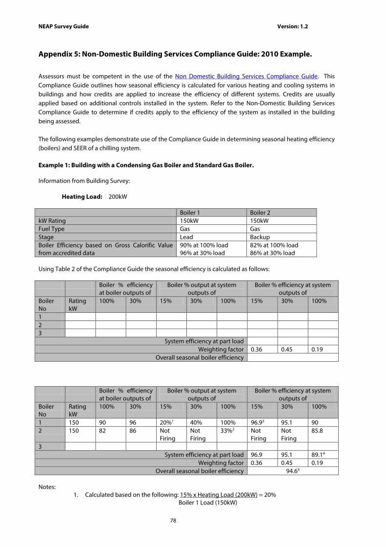
NEAP Survey Guide Version: 1.2
78
Appendix 5: Non-Domestic Building Services Compliance Guide: 2010 Example.
Assessors must be competent in the use of the Non Domestic Building Services Compliance Guide. This Compliance Guide outlines how seasonal efficiency is calculated for various heating and cooling systems in buildings and how credits are applied to increase the efficiency of different systems. Credits are usually applied based on additional controls installed in the system. Refer to the Non-Domestic Building Services Compliance Guide to determine if credits apply to the efficiency of the system as installed in the building being assessed. The following examples demonstrate use of the Compliance Guide in determining seasonal heating efficiency (boilers) and SEER of a chilling system. Example 1: Building with a Condensing Gas Boiler and Standard Gas Boiler. Information from Building Survey: Heating Load: 200kW Boiler 1 Boiler 2 kW Rating 150kW 150kW Fuel Type Gas Gas Stage Lead Backup Boiler Efficiency based on Gross Calorific Value from accredited data
90% at 100% load 96% at 30% load
82% at 100% load 86% at 30% load
Using Table 2 of the Compliance Guide the seasonal efficiency is calculated as follows: Boiler % efficiency
at boiler outputs of Boiler % output at system
outputs of Boiler % efficiency at system
outputs of Boiler No
Rating kW
100% 30% 15% 30% 100% 15% 30% 100%
1 2 3
System efficiency at part load Weighting factor 0.36 0.45 0.19
Overall seasonal boiler efficiency Boiler % efficiency
at boiler outputs of Boiler % output at system
outputs of Boiler % efficiency at system
outputs of Boiler No
Rating kW
100% 30% 15% 30% 100% 15% 30% 100%
1 150 90 96 20%1 40% 100% 96.93 95.1 90 2 150 82 86 Not
Firing Not Firing
33%2 Not Firing
Not Firing
85.8
3 System efficiency at part load 96.9 95.1 89.14
Weighting factor 0.36 0.45 0.19 Overall seasonal boiler efficiency 94.65
Notes:
1. Calculated based on the following: 15% x Heating Load (200kW) = 20% Boiler 1 Load (150kW)

NEAP Survey Guide Version: 1.2
79
2. Calculated based on the following: Heating Load (200kW) – Boiler 1 Load (150kW) = 33%
Boiler 2 Load (150kW)
3. Calculated by the linear interpolation ηb,p = η30% - (η30% - η100% ) * (q b,p – 30%)/ (100% – 30%)
η20% = 96 - (96 - 90 ) * (20% – 30%)/(100% – 30%)
η20% = 96.9
4. Calculated by dividing the thermal output of the system by the rate of fuel combustion, which is given by the sum of the boiler outputs divided by their individual operating efficiency.
η 100% = 200/ ((150*100%/90) + (150*33%/85.8)) = 89.1%
5. Calculated as the weighted average;
= 0.36* 96.9 + 0.45 * 95.1 + 0.19 * 89.1 = 94.6%
Example 2: Building with 2 Air Cooled Chillers. Information from Building Survey can be processed in a similar fashion for chillers in a similar fashion to Example 1 above: Cooling Load: 500kW Chiller 1 Chiller 2 kW Rating 250kW 250kW Stage Lead Backup Chiller Efficiency 2.5 at 100% load
3.5 at 50% load 2.5 at 100% load 3.5 at 50% load
The combined EER value is calculated as follows: Chiller efficiency at
chiller outputs of Chiller % output at system
outputs of Chiller % efficiency at system
outputs of Chiller Chiller
kW 100% 50% 25% 50% 75% 100% 25% 50% 75% 100%
1 250 2.5 3.5 50% 100% 100% 100% 3.5 2.5 2.5 2.5 2 250 2.5 3.5 Not
Firing Not Firing
50% 100% Not Firing
Not Firing
3.5 2.5
3 System efficiency at part load 3.5 2.5 2.76a 2.5
Weighting factor (based on unknown application load profile as per Compliance Guide Section 9.5)
0.25 0.25 0.25 0.25
Overall chiller SEER 2.82 b Notes:
• Calculated by dividing the thermal output of the system by the rate of fuel combustion, which is
given by the sum of the chiller outputs divided by their individual operating efficiency.
eer 75% = 375/ ((250*100%/2.5) + (250*50%/3.5))

NEAP Survey Guide Version: 1.2
80
= 2.76
• Calculated as the weighted average;
= 0.25* 3.5 + 0.25 * 2.5 + 0.25 * 2.76 + 0.25 * 2.5 = 2.815
Example 3: Existing Building with Gas Boiler and Controls. Information from Building Survey: Heating Load: 200kW
Boiler 1 kW Rating 300kW Fuel Type Gas Stage Lead Boiler Efficiency based on Gross Calorific Value 82% Temperature Controls TRVs on all radiators Optimised Start/Stop
Using Table 8 of the Compliance Guide the seasonal efficiency is calculated as follows: Heating Efficiency Credits Boiler Efficiency 82% System uses TRVs to ensure full building temperature control 1 System uses Optimised Start/Stop to achieve specified conditions during occupancy period
2
Total Credits 3
Effective boiler seasonal efficiency: = Boiler Efficiency + maximum of 4 heating efficiency credits = 82% + 3%
= 85%
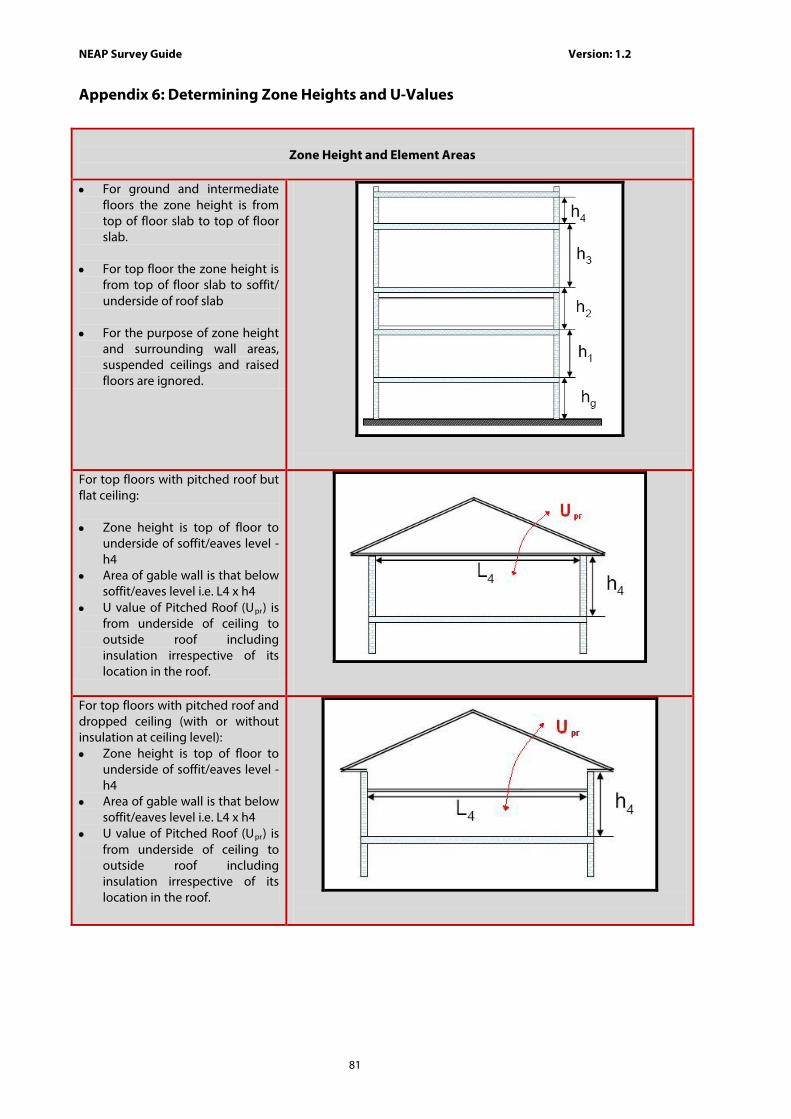
NEAP Survey Guide Version: 1.2
81
Appendix 6: Determining Zone Heights and U-Values
Zone Height and Element Areas
• For ground and intermediate
floors the zone height is from top of floor slab to top of floor slab.
• For top floor the zone height is
from top of floor slab to soffit/ underside of roof slab
• For the purpose of zone height
and surrounding wall areas, suspended ceilings and raised floors are ignored.
For top floors with pitched roof but flat ceiling: • Zone height is top of floor to
underside of soffit/eaves level - h4
• Area of gable wall is that below soffit/eaves level i.e. L4 x h4
• U value of Pitched Roof (Upr) is from underside of ceiling to outside roof including insulation irrespective of its location in the roof.
For top floors with pitched roof and dropped ceiling (with or without insulation at ceiling level): • Zone height is top of floor to
underside of soffit/eaves level - h4
• Area of gable wall is that below soffit/eaves level i.e. L4 x h4
• U value of Pitched Roof (Upr) is from underside of ceiling to outside roof including insulation irrespective of its location in the roof.

NEAP Survey Guide Version: 1.2
82
For top floors with pitched ceiling: • Zone height is top of floor to
underside of soffit/eaves level - h4 (not average room height)
• Area of gable wall is whole wall up to roof apex (shaded area)
• U value of Pitched Roof (Upr) is from underside of ceiling to outside roof.
For top floors with mono-pitched ceiling: • Zone height is top of floor to
weighted average height of all walls - h4av
• Area of gable wall is whole wall (shaded area)
• Note that zoning for daylit areas must be carried out manually in these circumstances.
• U value of Pitched Roof (Upr) is from underside of ceiling to outside roof.
For Room in Roof or Mansard Roof: • Zone height (hw1) = height of
vertical part of wall. If hw1 varies around the zone, calculate the area weighted average height.
• The U-value (Uw1) through the external walls should include any voids as appropriate.
• The U-value (Ur1) through the first roof construction X1 is roof structure only.
• The U-value (Ur2) through the second roof construction Y1 is from underside of ceiling to outside roof including insulation as appropriate and void.

NEAP Survey Guide Version: 1.2
83
For Room in Roof with Dormer Window • As per Room in Roof above. • Zone height (hw1) = height of
vertical part of wall. If hw1 varies around the zone, calculate the area weighted average height.
• Do not adjust zone height for dormer window
• The external elements, wall, roof and glazing of the dormer window should be included as normal.
• Zone manually for daylight areas (if glazing >20% of vertical wall area)
For Warehouse with unusable space above adjoining zone: • Zone height is top of floor to
underside of soffit/eaves level - h4
• Area of gable wall is whole wall up to roof apex (shaded area)
• Area of roof is (Y1 + Y2) x length of the zone
• Height of side walls shown as X 1 and h4
• Area of ground floor and area of zone is Z1 x length of the zone
• The internal elements shown as A1 and B1 should be added as appropriate.
For Warehouse with usable space above adjoining zone, the warehouse is split into two zones: • Zone height for Z1 is top of
floor to underside of soffit/eaves level - h4
• Zone height for Z2 is weighted average height of all walls - hav as per the monopitched ceiling guidelines.
• Area of gable wall for Z1 is whole wall up to roof apex (shaded area in yellow )
• Area of gable wall for Z2 is whole wall up to roof apex (shaded area in orange)
• Area of roof in Z1 is (Y1 + Y2) x length of the zone
• Area of roof in Z2 is (Y3) x length of the zone

NEAP Survey Guide Version: 1.2
84
Slab Thickness When there is insufficient proof of the actual slab thickness (not detailed in drawings for example), a default of 250mm is used. Ensure that where ceiling voids and raised floors exist that these are correctly identified. The depth of the ceiling voids and raised floors is included in the overall height of the zone. Check that documentary evidence is maintained to support entry.
Global Zone Height A global zone height can be set in iSBEM under General and Geometry -> Building Details. The value entered is given as the global or default zone height in each of the zones. The zone height can be altered, or use the global height for respective zones. Where a zone height differs from the global/default height, select the
global button and enter the actual zone height.

NEAP Survey Guide Version: 1.2
85
Appendix 7: Identifying the Heating System A7.1 Building Heating System Flow Chart

NEAP Survey Guide Version: 1.2
86
Table A7.1 Examples of Unheated Buildings The following outlines examples of unheated buildings:
Unheated Parameters Some Building Types to which the parameters may apply
Is this building: - an industrial building not intended for human occupancy over extended periods and where the installed heating capacity does not exceed 10 W/m2; or - a non-residential agricultural building where the installed heating capacity does not exceed 10 W/m2
• Warehouse and Storage
Is the building unheated due to a high internal load from a process providing the heating, for example a dry cleaners?
• Industrial Process Building
• Laundry
• Retail (Fast food outlet)
Shell and Core Building • Office
• Retail
• Industrial Process Building

NEAP Survey Guide Version: 1.2
87
A7.2 Zone Heating System Selection Flow Chart

NEAP Survey Guide Version: 1.2
88
Table A7.2 Examples of Unheated Zones The following outlines examples of unheated zones:
Where fixed space heating is present in the zone, the HVAC system is entered based on the iSBEM User Guide and NEAP Survey Guide.
Unheated Parameters Some Unheated Zone Types to which the parameters may apply
The zone does not have fixed heating and typically does not require conditioning based on the activity type (no red exclamation mark “!” shown in iSBEM) “Zones without HVAC system” is assigned to the zone.
• Storage Area
• Circulation Areas
• Storage – chilled
• Plantroom
• Warehouse Storage
The zone does not contain fixed heating and is indirectly conditioned by an adjoining zone open to the zone. HVAC system of the adjoining heated zone is assigned to the zone. See Survey Guide Section A4.3 and iSBEM user guide section 7.6.8
• Circulation Areas (open to conditioned spaces)
The zone does not contain fixed heating and is a transient space (not intended for human occupancy over extended periods)? “Zones without HVAC system” is assigned to the zone. See Survey Guide Section A4.3.
• Toilet
• Tea Making
• Changing Facilities
• Bathroom
The zone does not contain fixed heating and is heated by a process load within the zone? “Zones without HVAC system” is assigned to the zone. See Survey Guide Section A4.3.
• Industrial process area
• IT Equipment
• Data Centre
• Laundry
• Food Preparation
The zone does not have fixed heating and is a “Shell” (no lighting, heating, ventilation and cooling) ? eg speculative zones HVAC system assigned to the zone as per NEAP Survey Guide A4.8
• Speculative Office
• Speculative Retail
• Speculative Industrial
The zone does not have fixed heating, typically requires conditioning based on the activity type (red exclamation mark “!” shown in iSBEM) and does not meet conditions above. Default HVAC system assigned to the zone as per NEAP Survey Guide A4.3
• Cellular Office
• Open Plan Office
• Meeting Room
• Classroom
• Hall / Lecture Theatre/ Assembly Area
• Laboratory
• Consulting Room
• Bedroom

NEAP Survey Guide Version: 1.2
89
Appendix 8: Adjoining Conditioned and Unconditioned Spaces Heat losses through building elements, must be correctly accounted for in the BER assessment.
The building element within a zone must have the conditions in the adjoining space assigned to the element. The following flow chart gives details of when to assign alternate conditions:

NEAP Survey Guide Version: 1.2
90
Adjoining spaces, either within the building being assessed or the adjoining building are treated as follows in iSBEM:
a) “Conditioned Adjoining Space” if the space adjoining the element (zx/xx/xi) has the same activity as the zone (zx/xx) or is normally heated to similar levels as the zone (i.e. heated to a similar temperature (+/-5oC) for 90% or more of the duration of the zone being specified.)
b) “Unheated Adjoining Space” or “Strongly ventilated spaces” if the above condition is not met.
The heating regime of the adjoining space is determined as follows: 1) If there is access to details of the zones within the adjoining building, base the parameters for the
element on the activity and installed HVAC system within that zone. 2) If there is no access to the zones in the adjoining building, base the parameter for the element on the
building type using the following table of temperature profiles for common building types. These building types have been selected from the SBEM Activity Database for common building types typically adjoining a non domestic building. The table is based on the SBEM Activity Database for the main activities within each of the building types.
Building Type Weekly Temperature Profile Annual Temperature
Profile Airport Terminal Mon to Sun: 12oC - 0 to 24 All Year Transport Terminal Mon to Sun: 12oC - 0 to 24 All Year Community/Daycare Centre Mon to Fri:
Sat to Sun:
12oC - 0 to 7 22oC - 7 to 18 12oC - 18 to 24 12oC - 0 to 24
All Year
Primary Health Care Mon to Fri: Sat to Sun:
12oC - 0 to 6 22oC - 6 to 18 12oC - 18 to 24 12oC - 0 to 24
All Year
Further Education University Mon to Fri: Sat to Sun:
12oC - 0 to 7 20oC - 7 to 20 12oC - 20 to 24 12oC - 0 to 24
Jan 1 to Jan 12: 12oC Jan 13 to Mar 20: Weekly Profile Mar 21 to Apr 3: 12oC Apr 4 to June 12: Weekly Profile June 13 to Sept 25: 12oC Sept 26 to Dec 11: Weekly Profile Dec 11 to Dec 31: 12oC
Restaurant/public house Mon to Sun:
12oC - 0 to 6 23oC - 6 to 23 12oC - 23 to 24
All Year
Theatres/cinemas/music halls and auditoria
Mon to Sun:
12oC - 0 to 8 22oC - 8 to 22 12oC - 22 to 24
All Year
Office Mon to Fri: Sat to Sun:
12oC - 0 to 6 22oC - 6 to 19 12oC - 19 to 24 12oC - 0 to 24
All Year
Retail Mon to Sat: 12oC - 0 to 7 All Year
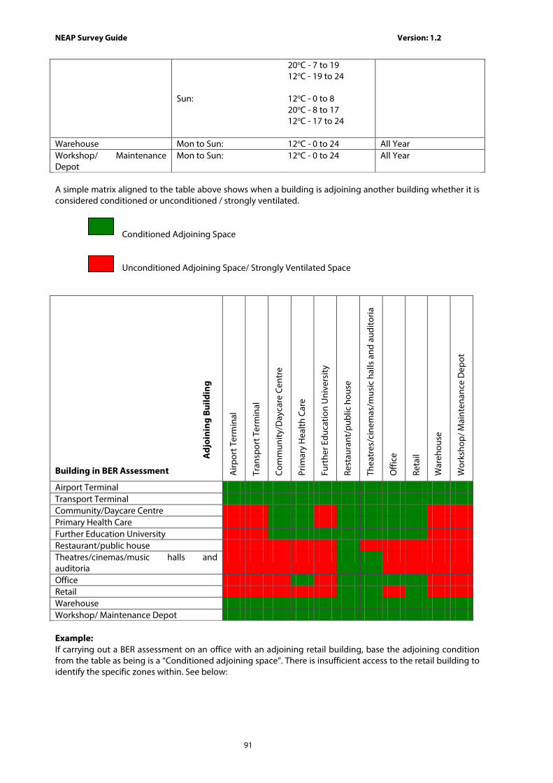
NEAP Survey Guide Version: 1.2
91
Sun:
20oC - 7 to 19 12oC - 19 to 24 12oC - 0 to 8 20oC - 8 to 17 12oC - 17 to 24
Warehouse Mon to Sun: 12oC - 0 to 24 All Year Workshop/ Maintenance Depot
Mon to Sun: 12oC - 0 to 24 All Year
A simple matrix aligned to the table above shows when a building is adjoining another building whether it is considered conditioned or unconditioned / strongly ventilated.
Conditioned Adjoining Space
Unconditioned Adjoining Space/ Strongly Ventilated Space
Adj
oini
ng B
uild
ing
Airp
ort T
erm
inal
Tran
spor
t Ter
min
al
Com
mun
ity/D
ayca
re C
entr
e
Prim
ary
Hea
lth C
are
Furt
her E
duca
tion
Uni
vers
ity
Rest
aura
nt/p
ublic
hou
se
Thea
tres
/cin
emas
/mus
ic h
alls
and
aud
itoria
Offi
ce
Reta
il
War
ehou
se
Wor
ksho
p/ M
aint
enan
ce D
epot
Building in BER Assessment
Airport Terminal Transport Terminal Community/Daycare Centre Primary Health Care Further Education University Restaurant/public house Theatres/cinemas/music halls and auditoria
Office Retail Warehouse Workshop/ Maintenance Depot Example: If carrying out a BER assessment on an office with an adjoining retail building, base the adjoining condition from the table as being is a “Conditioned adjoining space”. There is insufficient access to the retail building to identify the specific zones within. See below:

NEAP Survey Guide Version: 1.2
92
However if carrying out a BER assessment on a retail building with an adjoining office building: There is insufficient access to the office building to identify the specific zones within. Base the adjoining condition from the table as being an “Unheated adjoining space.” See below

NEAP Survey Guide Version: 1.2
93
Where an element is adjoining an Unheated Adjoining Space or a Strongly Ventilated space, the U value of the element is adjusted to account for the effect of the unheated space. The procedure for calculating the U-value is described in the Non Domestic Building Regulations Part L Technical Guidance Document and in Appendix A of BR 443:2006. The method in BR 443 is derived using EN 13789.
For adjoining buildings it may not always be possible to determine the parameters required to calculate the Ru value. The following conservative guidelines may be used to derive these parameters where relevant information is not available on the adjoining building: U-values of adjoining building’s external elements:
1. If the assessed and adjoining buildings were constructed at the same time and are of similar construction, the U-values of the external elements of the adjoining building should be based on the same U-values as the building being assessed. The building being assessed may have been upgraded since original construction, however unless the BER Assessor can provide documentary evidence to support that the adjoining building was upgraded, the U-values of the external elements of the adjoining building are based on the original construction.
2. If the adjoining building was constructed at a different time to the building being assessed, base the U-values of the external elements of the adjoining building on default U-values for the building age using the inference method.
3. If neither of the above options apply or if in doubt, use a conservative default of 2 W/m2K for all external elements of the adjoining building. This is the default value used in the BRE U-value calculator.
Measurements: 1. Base the estimated measurements of the adjoining building on the information available
during the site survey or other available information e.g. planning files etc. The measurements should be based on the most applicable conservative value with the Assessor commenting and keeping a record of the calculations.
2. Where access is restricted to the adjoining building, base the dimensions for the adjoining building on external dimensions.
3. If the external dimensions of the adjoining building are not accessible, estimate the size of the building as a proportion of the building being assessed. (for example it is twice the width of the building being assessed and half the height)
4. Where internal zones are not accessible in the adjoining building, the areas and volume should be based on the entire building.
Ventilation Rate: The air change rate within the Unheated Space is as per Table A5 of BR 443. The default air change rate is 3, to be used if the airtightness type of the unheated space is not known.
SEAI have developed an FAQ and calculation tool to assist assessors correcting the U-value adjacent to unheated spaces within a zone. Please refer to www.seai.ie/berfaq .

NEAP Survey Guide Version: 1.2
94
Appendix 9: Determining the Hot Water Storage Volume
Where there is access to the hot water storage unit, determine the storage volume as follows: a. Determine the hot water storage volume from a label on the storage unit, provided the label
also references a European or National Standard or is CE marked. b. Take note of the Manufacturer and Model of the unit and determine the volume from
literature from the manufacturer referencing the relevant standards. c. Take note of the Manufacturer and Model of the unit and contact the manufacturer
regarding the storage volume. The manufacturer must provide written confirmation of the storage volume.
d. Where data from the above sources is unavailable and the vessel is accessible, measure the volume of the unit on site. Further detail on this is provided below.
e. Where the hot water storage vessel is inaccessible, documentary evidence from the installer, architect or engineer identifying the volume of the installed vessel is used.
f. If none of these options are possible base it on the SBEM default. Measuring a Hot Water Storage Cylinder: 1) Measure the height and diameter of the hot water storage vessel. 2) For cylindrical vessels that are between 71 and 441 litres, choose the nearest height and diameter options
from the table below to determine the volume in litres. Insulation thickness is not included in the height or diameter measurement when using the table. The table below is based on BS1566 and applies to copper cylinders, however, these figures are also used for other types of storage vessels for the purposes of NEAP assessments. The storage vessel diameter is determined based on vessel circumference, dividing the circumference by π (3.14). Diameter should not include insulation thickness.
Diameter (mm) Height (mm) Storage volume
300 1600 96
350 900 72
400 900 96
400 1050 114
450 675 84
450 750 95
450 825 106
450 900 117
450 1050 140
450 1200 162
450 1500 206
500 1200 190
500 1500 245
600 1200 280
600 1500 360
600 1800 440 3) For cylindrical vessels outside this range, the volume is calculated based on the following:
V = (pi x r2) x h / 1000
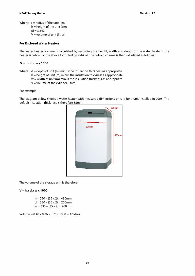
NEAP Survey Guide Version: 1.2
95
Where: r = radius of the unit (cm) h = height of the unit (cm) pi = 3.142 V = volume of unit (litres) For Enclosed Water Heaters: The water heater volume is calculated by recording the height, width and depth of the water heater if the heater is cuboid or the above formula if cylindrical. The cuboid volume is then calculated as follows: V = h x d x w x 1000 Where: d = depth of unit (m) minus the insulation thickness as appropriate.
h = height of unit (m) minus the insulation thickness as appropriate. w = width of unit (m) minus the insulation thickness as appropriate V = volume of the cylinder (litres)
For example The diagram below shows a water heater with measured dimensions on site for a unit installed in 2005. The default insulation thickness is therefore 35mm.
The volume of the storage unit is therefore: V = h x d x w x 1000 h = 550 – (35 x 2) = 480mm d = 330 – (35 x 2) = 260mm w = 330 – (35 x 2) = 260mm Volume = 0.48 x 0.26 x 0.26 x 1000 = 32 litres

NEAP Survey Guide Version: 1.2
96
Appendix 10: Selection of Solid Fuel Type.
Solid fuel appliances can be fuelled by coal, anthracite, smokeless fuel, dual fuel (mineral and wood) and biomass.
For solid fuel boilers and heaters the fuel type is chosen as follows, proceeding from points 1 towards 4 until a choice is made:
1) If the heating appliance is designed to burn only biomass, i.e. its design is such as to prohibit the use of any other fuel type, then the appropriate fuel type (biomass) should be selected. Otherwise biomass should not be selected. This can be demonstrated by one of the following:
i. Documentation showing that the product warranty is void if the product is used with any fuel type other than biomass ;
ii. Listing of the product under http://www.hetas.co.uk/ showing that the appliance burns biomass only.
Where there is any doubt about fuel type selection biomass should not be selected. 2) If the appliance is designed to burn a particular coal-based or peat-based fuel type, then
that should be chosen as the fuel. 3) If the appliance can burn more than one fuel type, the most likely non-biomass type should
be selected based on (a) the appliance design, and (b) the building location (taking account of smoke control areas and fuels common in the area).
The following table summarises the information above:
Scenario Biomass Manufactured smokeless fuel
One of coal or anthracite
Appliance can only burn biomass
Yes No No
Appliance can burn multiple solid fuels but a particular fuel is the most commonly available or applicable non-biomass fuel in the area
No Yes - Select manufactured
smokeless fuel when building is in “smoke control area” and the appliance can burn
multiple fuels
Yes - Select one of these fuels when building is in
non “smoke control area” and that fuel is
clearly the most commonly available fuel
in the area Smoke control areas (also called coal restricted areas) can be identified using the facility under http://maps.epa.ie or following guidance on the Department of Environment, Community and Local Government website. Individual Local Authorities may have further details.
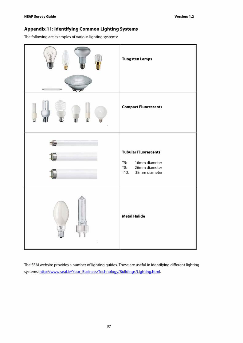
NEAP Survey Guide Version: 1.2
97
Appendix 11: Identifying Common Lighting Systems
The following are examples of various lighting systems:
Tungsten Lamps
.
Compact Fluorescents
Tubular Fluorescents T5: 16mm diameter T8: 26mm diameter T12: 38mm diameter
.
Metal Halide
The SEAI website provides a number of lighting guides. These are useful in identifying different lighting
systems: http://www.seai.ie/Your_Business/Technology/Buildings/Lighting.html.