Embed Size (px)
Citation preview
FFI-rapport 2012/00928
Non-destructive testing/inspection of composite materials – acoustic impact testing, TV holography and shearography
Martine Kvalbein og Tom Thorvaldsen
Norwegian Defence Research Establishment (FFI)
4 July 2012
2 FFI-rapport 2012/00928
FFI-rapport 2012/00928
379901
P: ISBN 978-82-464-2219-0
E: ISBN 978-82-464-2220-6
Keywords
Ikke-destruktiv testing/inspeksjon
Manuell tapping
Akustisk anslagstest
Shearografi
TV-holografi
Approved by
Einar Willassen Project Manager
Svein Rollvik Director of Research
Jan Ivar Botnan Director
FFI-rapport 2012/00928 3
English summary
This report provides an introduction to three different non-destructive testing/inspection
(NDT/NDI) methods applicable for damage detection in composite materials. A lot of techniques
have been developed for metals. However, composite materials often require other techniques,
and the damages are often more difficult to detect, due to anisotropic material properties and
combinations of materials with different mechanical behaviour and response. More experience is
required for inspection and testing of such materials.
The three inspection/testing methods covered in this report are acoustic impact testing, TV
holography and shearography. Various techniques within the three categories of methods are
developed, and for most of these the physical principle behind and the set-up is described. In
addition, it is pointed out what types of damages, defects and material imperfections that may be
detected with the different techniques, and what types of damages that are more difficult to detect.
One NDT/NDI method is not able to detect all types of damages. Hence, there is a need for
several techniques that can supplement each other.

4 FFI-rapport 2012/00928
Sammendrag
Denne rapporten gir en introduksjon til tre forskjellige ikke-destruktive test-/inspeksjonsmetoder
som er anvendbare for å finne skader i komposittmaterialer. En rekke teknikker har blitt utviklet
for metaller. Komposittmaterialer krever derimot ofte andre teknikker, og feilene er ofte
vanskeligere å finne, som følge av anisotrope materialegenskaper og kombinasjoner av materialer
med ulik mekanisk oppførsel og respons. Mer erfaring er nødvendig for inspeksjon og testing av
slike materialer.
De tre inspeksjons-/testmetodene som er inkludert i denne rapporten, er akustisk anslagstesting,
TV-holografi og shearografi. Forskjellige teknikker innenfor disse tre kategoriene er utviklet, og
for de fleste av disse er det fysiske prinsippet bak teknikken, samt oppsettet, beskrevet. I tillegg er
det pekt på hvilke typer skader, defekter og imperfeksjoner i materialene som kan oppdages, og
hvilke det er vanskeligere å finne.
Én test-/inspeksjonsmetode er ikke nok for å detektere alle typer feil og skader. Av den grunn er
det behov for flere teknikker som kan utfylle og supplere hverandre.
FFI-rapport 2012/00928 5
Contents
1 Introduction 7
2 Types of defects 8
3 Acoustic impact testing 10
3.1 Manual coin tapping 10
3.1.1 Description 10
3.1.2 Types of damages and materials 11
3.1.3 Advantages and disadvantages 11
3.2 Force-time analysis 11
3.2.1 Description 11
3.2.2 Types of materials and defects 12
3.2.3 Advantages and disadvantages 12
3.3 Mechanical impedance 12
3.3.1 Description 12
3.3.2 Mathematical modelling 13
3.3.3 Types of damages and materials 14
3.3.4 Advantages and disadvantages 14
4 TV holography 15
4.1 Description 15
4.2 Applied load 17
4.3 Mathematical description 18
4.4 Lock-in ESPI 18
4.5 Types of damages and materials 19
4.6 Advantages and disadvantages 20
5 Digital shearography 21
5.1 Description 21
5.2 Different set-ups/measuring techniques 22
5.2.1 Modified Michelson set-up 22
5.2.2 Prisms as shearing device 23
5.3 Phase-shifting 24
5.4 Optically excited lock-in shearography 25
5.5 Types of damages and materials 25
5.6 Advantages and disadvantages 25
6 Summary 26

6 FFI-rapport 2012/00928
Acknowledgement 27
Appendix A Additional sources 28
A.1 Links 28
A.2 Conferences 28
References 29

FFI-rapport 2012/00928 7
1 Introduction
Non-destructive testing (NDT) methods, or non-destructive inspection (NDI) methods, are
applied to determine the physical condition of an object, performed in a way, so that it is not
altering or permanently changing the properties of the object [2]. The main aim of the
testing/inspection is to detect damages and defects in the different materials of the object, as well
as in the structure as a whole, both during production and from in-service operations. For critical
parts of a structure, NDT/NDI hence contributes to maintain a safe use of the object. Applying
NDT/NDI methods may in many situations also be very cost and time effective, compared to
replacing parts or doing extensive repairs. This latter aspect is a key factor in the maintenance
program and the operability of a structure.
Numerous NDT/NDI methods exist, and these can be divided into categories, depending on the
physical principles on which they are based. Most NDT/NDI techniques used today belong to one
of the following groups [3]:
Acoustic impact methods
Thermography methods
Ultrasonic methods
Optical methods
Visual methods
Radiographic methods
Magnetic particle methods
Acoustic emission methods
Penetrant methods
Eddy current methods
Microwave methods
Ground-penetrating radar methods
The aim of this report is to give an introduction to some of the NDT/NDI techniques that are
relevant for composite materials. In the current report, we describe acoustic impact methods, as
well as shearography and the related TV holography method, which both belong to the category
denoted optical methods. Thermography and ultrasound techniques, which also will be referred to
in this report, will be covered more thoroughly in a separate and later FFI report. The choice of
methods investigated herein is to some extent based on the paper by Kaiser et al. [3], in which
NDT/NDI methods for examination of carbon fibre reinforced polymer (CFRP) materials are
ranked. The selection of methods is also based on the methods relevant for the Norwegian
Defence Logistics Organisation and the Norwegian defence industry as part of their in-service
maintenance procedures and product development, respectively.
The report is organized as follows: First, a general introduction to some of the different types of
defects typically found in composites for structural applications, i.e. sandwich structures and

8 FFI-rapport 2012/00928
monolithic fibre reinforced polymer (FRP) composite panels, is given. Then, the three above
mentioned NDT/NDI methods are described in more detail. For each technique, types of defects
that may be detected, and those that are more difficult to detect, are explained. Furthermore,
advantages and disadvantages of each technique are discussed. A summary table is provided at
the end of the report.
2 Types of defects
Defects and abnormalities in composites can occur both during production and in in-service
situations. The source of these abnormalities can generally be related to the materials themselves,
such as the mechanical properties of the fibres or the matrix, or the bonding between them.
Moreover, deviations from the specifications set for the manufacturing process or the presumed
in-service operations may also introduce defects in the composites [4]. Hence, the type and
combination of materials used is critical for the overall properties of the composite. A schematic
description of some typical types of abnormalities in layered composites, which will be referred
to in subsequent parts of the report, is shown in Figure 2.1.
(D)
(B)
Fiber breakage
Void Porosity Inclusion
(A)
(C)
Delamination
Skin-core separation
Figure 2.1 Schematic drawing of different kinds of abnormalities found in layered composite
structures.
(A) Skin-core separation in sandwich structures is an example of a core disbond. The
term disbond is referring to a separation between two (previously) adhesively joined
materials. A disbond where the two surfaces are still in contact with each other, or areas
where the laminae in a laminated composite are not separated yet, but where the bonding
qualities between them are very poor, are termed kissing bonds.
(B) Voids are typically describing air bubbles that are large enough to be individually
detected, while porosity is referring to a collection of very small voids that must be
detected as a gathered unit. Voids filled with some foreign material, induced during the
manufacturing process, are termed inclusions.
(C) Separations between the laminae in laminated structures are termed delaminations.
(D) Fiber breakage in a fiber reinforced composite.

FFI-rapport 2012/00928 9
First of all, for fibre reinforced materials, multiple factors of both the fibres and the matrix during
the manufacturing process can affect the quality of the produced object. If the fibres are bent in
some unintended way, the object will experience a reduction in both tensile and compressive
strength [4]. Also, faults, such as local occurrences of enlarged diameter or hollowness of the
fibres can lead to elevated stress concentrations, and hence an early failure. Furthermore, factors
such as the age of the material, the temperature cycle applied during the curing process, and
contamination during the production, can lead to both porosity and voids in the material, as well
as poorer bonding quality between the matrix and the fibres. This again can lead to undesired
concentrations of internal stresses.
According to Adams and Cawley [4], in-service defects of fibre-reinforced composites can be
divided into three main groups. The first is translaminar flaws, where the crack propagates across
different layers. Such defects are, however, uncommon, as resin rich areas will prevent the
translaminar crack growth, and the crack will instead disperse into delaminations, also termed
interlaminar cracks, which is the second group, see Figure 2.1C. This appears to be the most
common type of in-service defects for these types of materials. Due to possible air pockets or
enriched resin areas, the boundary between two adjacent laminae in a laminated structure is a
typical weak spot in the material, and delaminations tend to develop from such areas. Interlaminar
cracks do not necessarily affect the tension strength of the object, but they are more critical in
compression, where buckling may occur. The third type of in-service damages of fibre-reinforced
composites is transfibrous cracks, or fibre breakage, see Figure 2.1D. This error can reduce the
strength of the material dramatically, and hence lead to early failure of the entire object.
For adhesive joints, several sources of defects are possible. Most common are however cracks,
voids, porosity or poor curing in the adhesive layer of the joint [4]. In addition, disbonds between
the adhesive and the surface of the adherent may also take place. The term disbond is here
referring to a separation between two adhesively joined materials. A disbond where the two
surfaces are still in contact with each other, or areas where two laminae in a laminated composite
are not yet separated, but where the bonding qualities between them are very poor, are termed
kissing bonds. A schematic drawing of common layers in a composite-composite adhesive joint is
shown in Figure 2.2.
Adhesive Composite
Composite
Adherent
Adherent
Figure 2.2 Schematic drawing of the typical layers in a composite-composite adhesive joint. The thickness of
the adhesive layer is exaggerated.

10 FFI-rapport 2012/00928
3 Acoustic impact testing
Non-destructive techniques using the principles from acoustic impact testing is based on the idea
that the observable sound registered by knocking, or tapping, on a material, will be a function of
the bonding quality between the different components of the structure, as well as the number and
location of cracks and inclusions [3]. This implies that the registered sound normally will be
altered when there is an internal damage underneath the surface of a composite material,
compared to the sound signature of an undamaged composite. Due to the fact that the propagation
of sound depends on the density of the material, this method is more sensitive to damages in, or
close to the surface [5]. Note that inspection techniques relying on this principle in most cases
only provide information about the exact point being investigated, including the area beneath it.
Hence, to obtain information about the entire surface of the object, all of its (surface) area needs
to be examined [5].
This principle of surface tapping is the basis for several different test procedures. The techniques
varies from the basic manual tapping with a coin, to more advanced and automated methods that
are using special hammers, which, in combination with computers, analyze the sound response. In
the following, three commonly applied techniques using the tapping principle will be described.
3.1 Manual coin tapping
3.1.1 Description
The “original” coin tapping method is a manual test where the operator is tapping over the surface
of the object with a big coin, or a small hammer, as shown in Figure 3.1. This is one of the oldest
and, in principle, simplest non-destructive tests. The operator listens to the resulting sound to
find alterations, and hence indications of defects in the underlying material [6]. When tapping
over defective regions, with e.g. poor bonding quality, the sound will have more “hollow”
characteristics than for the intact areas [3]. In the same way, internal cracks will also change the
sound response from the object.
Figure 3.1 Coin tapping. Picture: Norwegian Defence Logistics Organization (FLO).

FFI-rapport 2012/00928 11
3.1.2 Types of damages and materials
For sandwich structures, manual coin tapping can detect both delamination in the laminate skins
and debonding between skin and core, as these types of damages will alter the responding sound.
Damages that lie deep inside a structure, such as porosity and fibre breakage, may be
undetectable with this method, as they give no audible (for the human ear) alteration of the sound
[3;6].
According to Kaiser and Karbhari [3], limited research has been conducted on the use of
manually coin tapping on CFRP components, so its efficiency or suitability for this type of
objects is somewhat unknown. Kaiser and Karbhari indicate that this may be due to the fact that
the results of this manual test relay on the subjective opinion, experience and skills of the
operator, and that a scientific measurement thus can be hard to obtain [3].
3.1.3 Advantages and disadvantages
The most significant drawback of the manual coin tapping method is, as mentioned above, that
the outcome of the test method is strongly operator-dependent [3]. First of all, the sensitivity of
the obtained information is generally limited by the sensibility of the human ear. Moreover, the
quality of the reported result depends on the operator’s level of experience from similar cases, as
well as the knowledge of the material properties, the production and repair procedures.
Furthermore, the test only gives information about the exact point being tapped. Thus, the entire
surface must be examined, which in fact could be a challenging and time consuming task (i.e.
when conducted manually).
On the positive side, manual coin tapping seems to be simple, relatively fast and a good
supplement to other methods [3]. The only tool required is the tapping hammer (or a set of these
for different materials and sound responses). In addition, it does not require any specific areas for
performing the examination, such as protective walls, and the method can be applied to both
composites and metal structures with any geometric shape and material combination.
3.2 Force-time analysis
3.2.1 Description
The reason for the sound variation when tapping over damaged and undamaged areas is that the
actual force applied is altered. In damaged areas, the local stiffness of the material is reduced,
giving a longer duration and a lower frequency of the sound [5]. As a consequence, the force
applied to the structure is decreased. One way of reducing the operator-dependency and thereby
improving the quality of the results from the manual coin tapping test, described in Section 3.1, is
therefore to use a hammer that measures the applied force and the duration of the resulting sound
[3]. This is referred to as a force-time analysis.

12 FFI-rapport 2012/00928
A description of the frequency of the sound is obtained by performing a Fourier transformation on
the measured force-time relation [5] 1. Accordingly, areas with a relatively lower frequency,
compared to the rest of the surface, will have a higher probability of internal defects being
present.
As an alternative to monitoring the force-time relation, it is possible to directly measure the
frequency of the produced sound [5]. However, a main disadvantage of this particular procedure
is that the results, in the same way as for the manual coin tapping test, will be sensitive to back-
ground noise.
3.2.2 Types of materials and defects
The force-time analysis procedure will only detect damages that alter the stiffness of the material,
such as debonds and delaminations [5]. As an example, Kaiser and Karbhari [3] showed that
delamination in graphite-epoxy composites can be detected by comparison of duration times.
However, they experienced problems when trying to detect fibre breakage and fibre
misalignment.
3.2.3 Advantages and disadvantages
With a specialized tapping device, the interpretation of the coin tapping procedure is less
operator-dependent, compared to the manual variant. However, both force-time relations and
frequency spectra still need to be interpreted by an experienced operator [3], and it is still a
surface inspection method.
It should also be remarked that the force-time analysis test is insensitive to background noise,
which could be a problem in the manual version [5]. Also, the sensitivity of the procedure is
depending on the difference in stiffness between the hammer and the material [5], and hence the
quality of the results may be device-dependent.
3.3 Mechanical impedance
3.3.1 Description
Measurement of the object’s resistance to motion is another method where the principle from
acoustic impact testing is employed. This resistance is termed mechanical impedance ( Z ), and
can be expressed as the ratio between the force applied to a point F , and the resultant velocity v
of the surface at that point [6],
FZ
v (3.1)
1 A Fourier transformation is a mathematical operation that transforms the sound signal input into its
associated frequencies.

FFI-rapport 2012/00928 13
In the mechanical impedance method, one tries to detect areas in a layered structure where one or
more of the layers are separated from the base layers.
In an undamaged area, Z will depend on the contact stiffness between the hammer and the
structure as a whole, i.e. all of the material beneath, at the point where the hammer hits. This is
indicated by the blue arrow in the left part of Figure 3.2, for an object with perfect bonding
between the layers through the thickness. The value of Z in a layered structure with defects, will
only be related to the material above the damage area. This is indicated by the green arrow in the
right part of Figure 3.2 for a layered structure with a disbond or void in the glue line/layer
interphase. Since the dependent region is changed in the damaged state, compared to the
undamaged state, the mechanical impedance will be altered as well. Hence, the change in
mechanical impedance can be applied to detect internal defects of this type. A single frequency,
typically being between 1 and 10 kHz, is used when carrying out the measurements.
In this procedure, reference values need to be obtained for each new object [6]. The hammer
measures the force applied to the structure, and this is used in the calculation of the mechanical
impedance. The obtained information can be expressed as a map describing the underlying
properties of the surface [6], somewhat similar to an ultrasonic C-scan, see e.g. [7;8] .
The sensitivity of the mechanical impedance method depends on the material of the object and
types of defects present. Best results are obtained when the base structure is stiff and the layer
above the damage is thin [6;9].
3.3.2 Mathematical modelling
Defects are, as for the coin tapping methods, detected by a significant reduction of the local
stiffness of the structure at a given point. Mathematically a defect can be modelled as a spring,
where the spring stiffness is depending on the layers above the damage [9]. At a given point on
the surface, only the total stiffness k can be measured.
Glue line/
layer interphase
(exaggerated
thickness)
Debond/void Material base
Figure 3.2 The left drawing shows a undamaged area, where the mechanical impedance depends on
all of the underlying structure at the point being tapped. In the right hand side drawing, a
damage is present, and here the mechanical impedance depends only on the part of the
structure that is between the hammer and the damage/debond.

14 FFI-rapport 2012/00928
However, the total stiffness is related to the finite contact stiffness,ck , between the transducer and
the object, and to the defect stiffness,dk , defined by the distance from the damage to the surface.
The relation between k , ck and
dk can be expressed as follows [9]:
1 1 1 or c d
c d c d
k kk
k k k k k
(3.2)
In normal areas, dk is infinite, and hence ck k . The finite contact stiffness ck will limit the
sensitivity of this test. To obtain a suitable test sensitivity, the order of dk therefore needs to be
lower than the order of ck .
3.3.3 Types of damages and materials
The method is applicable for detecting defects that lead to a separation, i.e. delamination, between
two or more layers in a layered composite structure [9], but it is not usable for revealing
transverse cracks in the material [9]. Moreover, mechanical impedance can be employed for
detecting disbonds, as well as voids, in adhesive joints.
The capabilities for the mechanical impedance method was thoroughly investigated in the SaNDI
project [6]. As concluded in the project report, skin-core separation and local contact damage in
sandwich structures, where the size of the damaged area is larger than 50mm in diameter, are
detectable with moderate accuracy by the method. Furthermore, this technique is most efficient
for detecting damages close to the surface of sandwich structures, but it is not appropriate for
detecting damages that are located deep into the core material or close to the back wall of the
object.
3.3.4 Advantages and disadvantages
It is relevant in this case to compare the mechanical impedance method to the NDT methods
using ultrasound to detect damages and abnormalities. First of all, mechanical impedance has the
advantage that it is quite fast and does not require the use of a coupling media between the
transducer and the object; most ultrasound methods require a coupling media to be applied.
Concerning inspection of honeycomb structures, mechanical impedance has the benefit that the
output of the test is less dependent on the placement of the transducer in relation to the damage
[9]. This is due to the fact that mechanical impedance uses sound waves with lower frequencies,
and hence longer wavelengths than ultrasonic signals. On the other hand, the use of a larger
wavelength will increase the minimum size of a detectable defect. As the local stiffness of
honeycomb structures is strongly dependent on the bonding qualities between the skin and core,
the mechanical impedance can be very effective for studying such structures [9].
One restriction of the mechanical impedance technique is that it can only detect defects that are
parallel to the surface of the structure, i.e. delaminations and debonds.

FFI-rapport 2012/00928 15
4 TV holography
NDT methods using classical holography is based on comparison of double exposed holograms
of the object. One of the holograms is from a condition where the object is under stress, while in
the other hologram the object is in an unstressed state. The fundamental idea behind this method
is that the topology of the surface will be altered when the object is subjected to stress, and that
the degree of change will be different in damaged areas compared to undamaged areas. Hence, by
comparing the unstressed and stressed conditions, a description of the surface deformation under
stress is obtained, displayed as a fringe pattern. An abnormality in the pattern could imply a
damage inside the object in the given area [10].
Producing holograms is a quite time consuming procedure, and, as an improvement of this
method, TV holography, often referred to as Electronic Speckle Pattern Interferometry (ESPI) in
the optical literature, has been developed [10]. In TV holography, the speckle patterns of the
surface of the object is compared, instead of the holograms. The speckle pattern is the unique
combination of dark and bright spots, i.e. the “speckles”, which are obtained when a coherent
light is sent to illuminate an optically rough surface [11]. By detecting phase changes numerically
in these patterns, the duration and processing time of the method is greatly reduced.
Concerning the list of different types of NDT methods described in Section 1, TV holography is
classified as an optical method.
4.1 Description
In TV holography, a laser source with large longitudinal coherence is used. The beam of laser
light is split into two separate beams, an object beam and a reference beam [10], see Figure 4.1.
The object beam is expanded by an expansion lens, before it is sent to illuminate the object. The
beam will then be reflected backwards from the surface, and sent through a lens. The reference
beam is also expanded by a lens. Finally, the reflected object beam is recomposed with the
expanded reference beam, and recorded using video image sensors, such as CCD. Due to the fact
that the two beams are close to collinear, there will be an interference pattern with spatial periods
large enough to be detected by a CCD camera. The interference is producing a speckle pattern of
the surface of the object, which then is observed by the CCD camera, and furthermore processed
and stored on a computer. The object wave hence provides a deformation map of the object’s
surface that can be used for inspections.
The reference beam can, in addition, be sent through a computer controlled reference modulation
unit, before it is recomposed with the object beam [12]. With this unit, it is possible to add an
artificial vibration or deformation to the signal. This, in combination with numerical algorithms,
enhances the quality of the results. A set-up with this modulation unit included is showed in
Figure 4.2.
16 FFI-rapport 2012/00928
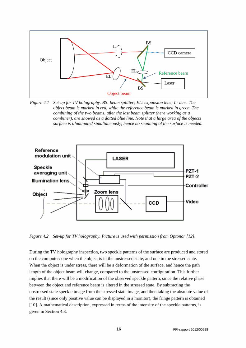
Figure 4.2 Set-up for TV holography. Picture is used with permission from Optonor [12].
During the TV holography inspection, two speckle patterns of the surface are produced and stored
on the computer: one when the object is in the unstressed state, and one in the stressed state.
When the object is under stress, there will be a deformation of the surface, and hence the path
length of the object beam will change, compared to the unstressed configuration. This further
implies that there will be a modification of the observed speckle pattern, since the relative phase
between the object and reference beam is altered in the stressed state. By subtracting the
unstressed state speckle image from the stressed state image, and then taking the absolute value of
the result (since only positive value can be displayed in a monitor), the fringe pattern is obtained
[10]. A mathematical description, expressed in terms of the intensity of the speckle patterns, is
given in Section 4.3.
EL
L BS
BS
EL
Object beam
CCD camera
Laser
Object
Reference beam
Figure 4.1 Set-up for TV holography. BS: beam splitter; EL: expansion lens; L: lens. The object beam is marked in red, while the reference beam is marked in green. The combining of the two beams, after the last beam splitter (here working as a combiner), are showed as a dotted blue line. Note that a large area of the objects surface is illuminated simultaneously, hence no scanning of the surface is needed.

FFI-rapport 2012/00928 17
4.2 Applied load
To obtain the stressed state image, some type of loading must be applied to the object. Possible
sources of this induced stress are air pressure, vibration, thermal loading or other kinds of
mechanical loading [13]. The purpose of the applied loading is to maximize the change of the
surface, to detect internal damages or abnormalities. Therefore, the most efficient type of loading
will vary from case to case, among others, depending on the behaviour and properties of both the
object and the expected abnormalities.
An appropriate mechanical loading will generally result in excessive movement of the surface.
While by such a loading one is able to detect debonds, it will also increase the chance for false
positive responses. This is because it is plausible that the undamaged areas of the surface, due to
this treatment, will be significantly altered as well. That is, a mechanical loading will produce
dense fringe patterns, and it will then be difficult to pick out interior faults from fringe
abnormalities [14].
The use of air pressure, which is one special, but efficient, type of mechanical loading, has a
lower chance for false positive test results. This type of load is very effective for detecting
internal damages, such as subsurface flaws, especially if internal pressure and vacuum chamber is
used [14]. With the use of vacuum, TV holography can detect debonds with closed boundary, but
not debonds at the edges [15].
By applying thermal loading in the form of heat, debonds and cavities may be detectable by their
expansion [14]. This procedure can also detect defects that alter the heat conductivity of the
material, and hence adjust the normal displacement of the heated surface. Note that composites, in
general, have a relatively low conductivity, and this enhances the possibility for observing such a
heat induced pattern in these materials, compared to for example metal; a study of the thermal
conductivity of some composite materials has been conducted by Mutnuri [16].
With vibration loading, the object is typically excited sinusoidally [14]. Applied vibration can
detect defects inside the object, as they under this type of loading may vibrate stronger than the
rest of the material. Note that small damages need a high frequency to obtain an altered resonance
frequency, compared to the rest of the material [14]. However, these high frequencies might be
hard to detect. The use of vibration as the applied load, is in many cases both faster and easier to
perform than using air pressure, heat or other types of mechanical loading.

18 FFI-rapport 2012/00928
4.3 Mathematical description
As described in Section 4.1, the speckle pattern for the unstressed and stressed states can
mathematically be expressed by the intensity, I . The unstressed state can be written as [10]
(1 cos )oI I (4.1)
where oI refers to the object image, and to the random phase angle due to the optically rough
surface of the object. In the stressed state, the phase change is introduced, due to the
deformation, and the intensity 'I can now be expressed as
' (1 cos( ))oI I (4.2)
The fringe pattern fI is obtained by subtracting the unstressed intensity from the stressed
intensity, and then using the absolute value of the result,
(cos( ) cos ) 2 (sin( )sin( ))2 2
f o oI I I
(4.3)
This resulting fringe pattern describes the topology of the surface, where the fringes correspond to
the contour lines in a map [17]. Abnormalities in this fringe pattern imply possible damage
underneath the corresponding areas. Since TV holography is measuring the absolute displacement
of the surface, any vibration or other disturbance of the object’s position, between or during the
two obtained speckle patterns, disturbs the quality of the result.
4.4 Lock-in ESPI
The normal deformation of the surface under stress can hide the altered deformation induced by
internal defects. As an improvement of the regular ESPI technique, a new procedure, applying the
principles from lock-in thermography [3;18-20], has been developed. This method is termed lock-
in ESPI [21].
In lock-in ESPI, a computer controlled heat source is added to the regular set-up for ESPI, used to
induce modulated thermal excitation into the object. This excitation will lead to a corresponding,
modulated spatial alteration of the surface. The regular ESPI set-up is used to monitor these
changes, in addition to the induced modulated heat.
As the first step, modulated heat is induced into the object, and a series of images of the effects on
the surface is obtained. The processing of these images is then done in two steps [21]. First, a map
of the height change of the surface is produced. Second, a Fourier transform analysis is performed
on this height distribution, and a description of the height modulation is obtained. Finally,
information is employed to establish descriptions of the amplitude and phase distribution. The
phase distribution is used to obtain information about the presence of internal defects.

FFI-rapport 2012/00928 19
Compared to regular ESPI, lock-in ESPI provides a significant improvement of the signal-to-
noise ratio (SNR), as well as an enhancement of the probability of detection (POD) [21]; POD
denotes the method’s probability for detecting a given type of discontinuity in the material [2]. By
varying the lock-in frequency, it is also possible to perform a depth analysis of the defects [21].
4.5 Types of damages and materials
TV holography is detecting abnormalities by applying the displacement field of the surface under
stress. Thus, this method is most suitable for detecting defects in, or close to, the surface;
generally it is most efficient for testing of plate and shell structures [10]. The types of defects that
are possible to detect with TV holography, extensively depend on the type of applied load.
However, defects, such as debonds, cavities and abnormalities that alter the heat conductivity of
the material, are commonly detectable.
A set-up for both TV holography and shearography (described in Section 5) is shown in Figure
4.3. The TV holography equipment is, among others, applied for inspection of composite shell
structures.
Figure 4.3 TV holography set-up. The composite structure is excited using heat.

20 FFI-rapport 2012/00928
Figure 4.4 TV holography image of a composite shell structure. Defect after dropping of the
structure onto a concrete floor from a relatively low height.
An example of a TV holography image of a damaged area is shown in Figure 4.4. In this case, a
composite structure has by accident been dropped onto a concrete floor from a relatively low
height. There is no visible (for the human eye) defect of the surface, but the structure is in fact
seriously damaged, and the strength is reduced considerably.
4.6 Advantages and disadvantages
TV holography is a contactless and sensitive method that makes it possible to examine large
surface areas at the same time. Since it does not require any scanning of the surface, TV
holography is a quite time efficient method [10].
Even though ESPI, or TV holography, tolerates more excessive displacements than traditional
holography, it is still very sensitive. Any movement between the two beams will affect the
obtained fringe pattern. According to Cawley [22] and references therein, tolerated object motion
under ESPI is about 100 µm. To ensure the quality of the result, a non-vibrating table is often
needed [10]. This is perhaps the main disadvantage of TV holography, as this equipment is
impractical, or even impossible to use for testing of larger structures and/or for in-service
inspections. In addition, due to the use of laser, a separate room must be dedicated to the testing.
As TV holography only detects damages that actually affect the object under stress, only the more
serious abnormalities are detected by this method [10]. Even though this property in some

FFI-rapport 2012/00928 21
situations may be an advantage, the need for inducing stress into the object is generally a
drawback of this method.
The interpretation of the fringe pattern obtained by TV holography is often easier to perform than
the interpretation of the pattern from digital shearography, described in Section 5. A further
comparison between digital shearography and TV holography is found in Section 5.6.
5 Digital shearography
Digital shearography is nowadays often referred to as just shearography, as the images are
always digitalized. This method is similar to TV holography described in Section 4. It is an
optical NDT method that uses laser light to detect defects by altering of the surface topology
under stress. The term laser shearography is in some cases also used for this method [6]. While
TV holography is detecting damages and abnormalities from the displacement, i.e. from the
absolute movement of points on the surface of a structure or component, shearography is
detecting them by their inducement of elevated strain, i.e. a description of the derivative of the
same displacement field [10]. In this way, the procedure is more resistant to vibration and other
disturbing movements than TV holography [3].
Note that shearography in some papers is referred to as Electronic Shear Interferometry (ESI)
[23] and also Speckle Pattern Shearing Interferometry [24].
5.1 Description
In the general set-up for digital shearography, a beam of coherent laser light, i.e. light where all
the waves have the same phase and frequency [1], is expanded (by a lens) before it is sent to
illuminate the object’s surface. The diffuse light reflected from this surface is then sent through a
shearography camera, which is shearing and recording the received signals [11;22]. A computer
processes this information to produce a speckle pattern of the surface of the object. This speckle
pattern is random, due to the fact that the object generally has a rough surface. Two speckle
patterns are created: one under the unstressed condition, and one when some kind of load is
applied. The combination of the two patterns gives a new fringe pattern that describes the first
derivative of the displacement.
Possible types of applied load can, independent of the type of shearing device used, be thermal
exposure, vacuum, pressure, mechanical vibrations or static loading, i.e. similar to those used in
TV holography, see Section 4.2 [6]. The aim should, however, be to maximize the change in the
surface, due to elevated stress in the damaged area, so that this can be detectable by the principles
of shearography. Hence, the most efficient type of loading will depend on the given situation.
According to Diamanti et al. [25], vacuum is commonly used as loading for detection of debonds
in composite materials. Examples of shearography set-ups using the different stress mechanisms
may also be found in the report from the SaNDI project [6], where test cases and images are
displayed, together with method requirements, functionality, time and cost information.

22 FFI-rapport 2012/00928
The overall set-up for shearography is very similar to TV holography, as shown in Figure 4.3,
with the main difference being the unit receiving and processing the data.
5.2 Different set-ups/measuring techniques
The set-up for the shearing of the reflected light varies between the different measuring
techniques found in the literature. Several papers describe a set-up that uses a beam splitter and
mirrors for obtaining the shear, i.e. the lateral offset, or distance, between the two beams. Two
overlapping pictures then give the interferogram. This is referred to as the modified Michelson
set-up, see e.g. [1;6;11;12;24]. Hung et al. [10;26;27], among others, instead use a prism and a
polarizer to obtain the same effect as from beam splitting. According to Kim [28], NDT methods
using the principle of shearography can generally be divided into these two main groups: 1)
methods using a Michelson interferometer, and 2) methods that are using other shearing elements,
such as prisms or glass wedges. We will describe them in the following.
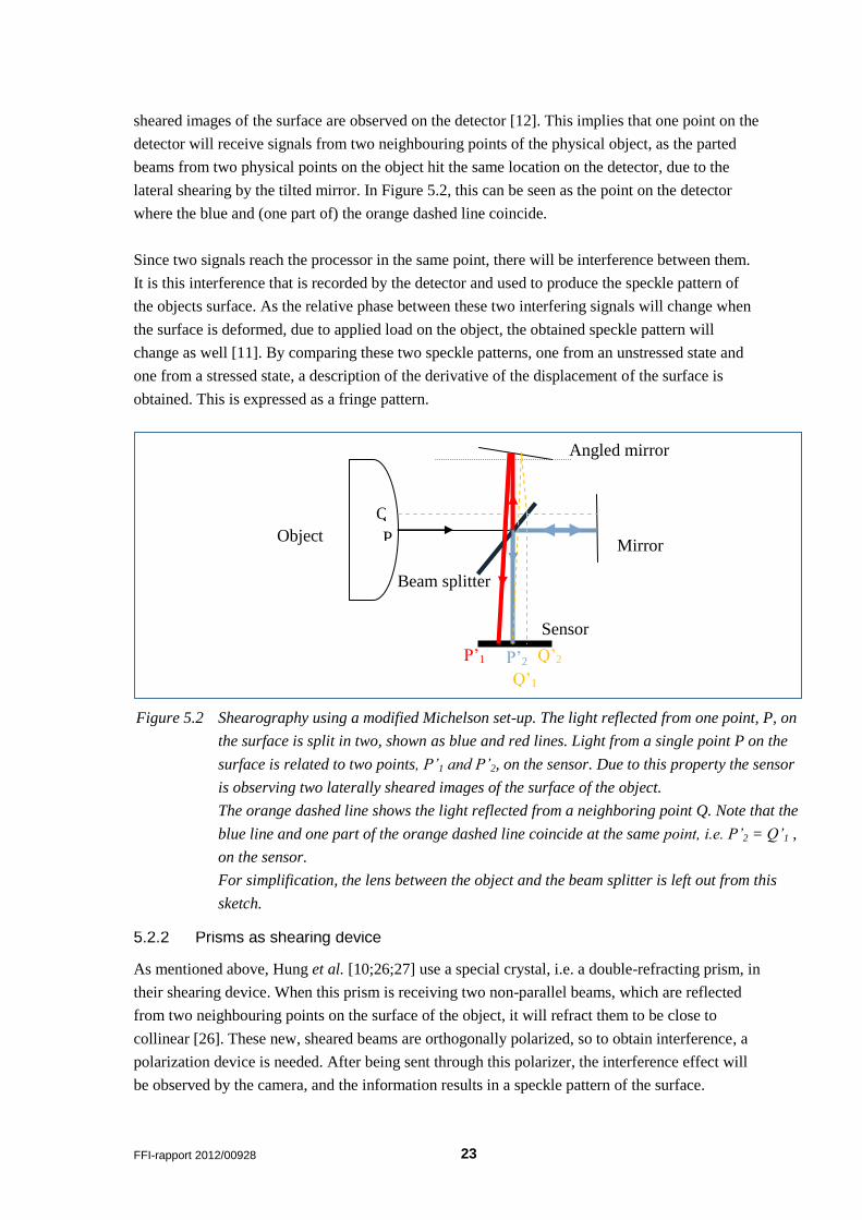
5.2.1 Modified Michelson set-up
In the modified Michelson set-up, also referred to as an Michelson interferometer [28], the
shearing of the reflected light from the surface is done by the use of a beam splitter and two
mirrors, see Figure 5.1. The light reflected from a random point on the surface will, when it is
sent through the beam splitter, be divided in two new beams, marked as blue and red lines in
Figure 5.2. They are referring to the part of the beam that is going straight through the beam
splitter, and the other part that is reflected. After this, each of these parts is sent towards one of
two mirrors that are reflecting the light towards a CCD camera. The camera is observing and
recording the information, which is afterwards processed by a computer, and stored as a speckle
pattern of the surface.
In the modified Michelson set-up, one of the mirrors has a small tilt, so the light reflected by this
mirror will be laterally displaced on the detector, compared with the other parted beam.
Accordingly, the original reflected light beam from one particular point on the surface will be
related to two different points on the detector [11], as shown in Figure 5.2. Hence, two laterally
Figure 5.1 Shearography using a modified Michelson set-up. Picture is used with permission
from Optonor [1].
FFI-rapport 2012/00928 23
sheared images of the surface are observed on the detector [12]. This implies that one point on the
detector will receive signals from two neighbouring points of the physical object, as the parted
beams from two physical points on the object hit the same location on the detector, due to the
lateral shearing by the tilted mirror. In Figure 5.2, this can be seen as the point on the detector
where the blue and (one part of) the orange dashed line coincide.
Since two signals reach the processor in the same point, there will be interference between them.
It is this interference that is recorded by the detector and used to produce the speckle pattern of
the objects surface. As the relative phase between these two interfering signals will change when
the surface is deformed, due to applied load on the object, the obtained speckle pattern will
change as well [11]. By comparing these two speckle patterns, one from an unstressed state and
one from a stressed state, a description of the derivative of the displacement of the surface is
obtained. This is expressed as a fringe pattern.
5.2.2 Prisms as shearing device
As mentioned above, Hung et al. [10;26;27] use a special crystal, i.e. a double-refracting prism, in
their shearing device. When this prism is receiving two non-parallel beams, which are reflected
from two neighbouring points on the surface of the object, it will refract them to be close to
collinear [26]. These new, sheared beams are orthogonally polarized, so to obtain interference, a
polarization device is needed. After being sent through this polarizer, the interference effect will
be observed by the camera, and the information results in a speckle pattern of the surface.
Q’1
P’1 P’2
Sensor
Q’2
Beam splitter
Angled mirror
Object Mirror
P
Q
Figure 5.2 Shearography using a modified Michelson set-up. The light reflected from one point, P, on
the surface is split in two, shown as blue and red lines. Light from a single point P on the
surface is related to two points, P’1 and P’2, on the sensor. Due to this property the sensor
is observing two laterally sheared images of the surface of the object.
The orange dashed line shows the light reflected from a neighboring point Q. Note that the
blue line and one part of the orange dashed line coincide at the same point, i.e. P’2 = Q’1 ,
on the sensor.
For simplification, the lens between the object and the beam splitter is left out from this
sketch.

24 FFI-rapport 2012/00928
A schematic description of the set-up can be seen in Figure 5.3. The interference is observable by
the CCD camera (similar to the Michelson set-up), due to the effect of the shearing device, as this
is reducing the spatial frequency of the interference fringes [26]. Also note that the process of
bringing the light reflected from two neighbouring points on the object to coincide at one point on
the detector of the CCD camera, is equal to letting the light from one point on the object split into
two different points on the same detector [10] .
Hung and Ho [26] on their side prefer using a Wollaston prism as a shearing device, as this prism
has a wider viewing field, producing fringes with higher quality, and is more light efficient.
However, the phase-shifting technique (see Section 5.3) is easier preformed on set-ups using a
Michelson interferometer than on those using a Wollaston prism as the shearing device [28].
Note that the set-ups described above are used for measuring of out-of-plane strains. If instead in-
plane strain is to be measured, a different set-up with a dual illumination of the object is needed
[27].
5.3 Phase-shifting
Phase-shifting techniques are added to the original set-up of digital shearography2 to obtain an
automated determination of the fringe phases in the output of the test; a manually interpretation of
the images is often challenging [28]. An additional phase is added to the speckle pattern multiple
times, and this makes it possible to automatically obtain information about the phase-change
distribution of the speckle pattern. The determination of this distribution is performed based on
the assumption that the random phase of the speckle pattern remains constant during deformation,
but that the total phase is altered, due to addition of the phase change [26].
This phase-shifting can be performed in several different ways. It is possible to tilt either the
object or the light beam, translating the shearing device to use a variable wave retarder, or to use
polarization to manipulate the wave front. The latter is described by Hung and Ho [26], where a
prism is used as a shearing device. In the modified Michelson set-up, the phase-shifting
technique is being accomplished by letting the non-tilted mirror be assembled to a pizoelectrical
2 Phase-shifting techniques are also applied in TV holography.
Object CCD camera
Shearing device Polarizer
Figure 5.3 Set-up for shearography that uses a double refractive prism as a shearing device.
FFI-rapport 2012/00928 25
crystal. This is inducing a linear movement on the mirror, and hence adding the desired
additional phase [28].
5.4 Optically excited lock-in shearography
Another way of improving the results obtained form shearography is to make use of the lock-in
principle. In optically excited lock-in shearography, modulated heat is induced onto the object by
letting a lamp with modulated intensity illuminate the surface [11]. This will lead to a periodically
change of the surface temperature of the object, followed by a thermal wave of heat transmitted
through it. As this wave will be reflected by internal defects in the material, the deformation state
of the surface of the object will be altered.
During this periodically excitement of the object, a speckle pattern of the surface is continuously
recorded. By adding a temporal phase-shift, and then performing a comprehensive analysis of the
images, a thermal lock-in phase image, that is displaying the local delay in thermal phase between
the excitement and the response, is obtained. This image combines the information from a
complete series of recorded pictures, and the phase information is used to detect damages.
5.5 Types of damages and materials
Damages are detected by shearography if they lead to elevated strain on the surface when the
object is exposed to stress. The areas with elevated strain levels can be recognized as
abnormalities in the fringe pattern. For example, debonds will be displayed as butterfly-like
shapes [26]. The outer size of the butterfly describes the actual size of the debond, while the
number of fringes is correlated to how deep in the structure the defect lies. The closer the defect is
to the surface, the more fringes will be observed. Actually, the density of the fringes is inversely
proportional to the cube of the depth of the defect, given that the debonds have equal size [26].
Since most damages, unless they are located very deep in the structure, will affect the strain on
the surface, damages in both the surface and more deeper structures can be detected with
shearography [27]. In composite laminates, debonds are detectable by shearography with good
security [26]. This method can also be applied for detecting delamination and edge pullout [10].
5.6 Advantages and disadvantages
One advantage related to shearography, is that it is contactless. Moreover, it is possible to
examine large areas at the same time. Hence, no scanning of the surface is needed, as is the case
for, among others, coin tapping and ultrasound methods. The restrictions on the size of the
(simultaneously) examined area lies on the intensity and broadness of the laser beam [3], as well
as the size of the viewing field of the shearing device. A general disadvantage of this method is
that the object actually needs to be in a loaded state. This is not required when using, for example,
ultrasonic methods.
Furthermore, shearography (and TV holography) are only able to detect damages that actually
changes the strain of the surface of the object [10]. For example, since there is no obvious
26 FFI-rapport 2012/00928
correlation between porosity and measurable surface deformation, this type of damage can be
difficult to detect [29].
The shearography method also needs visual access to the surface of the object, and sufficient
space in front of the object to set up the equipment. To reduce the demand on the required area in
front of the surface, Schuth et al. [24] took advantage of the features of endoscopy. More detailed
description of this technology can be found in their paper and the references therein.
For translucent and mirror-like surfaces, it might be necessary to paint the surface to reduce the
direct reflex, since this will create weaker fringes on the pattern, due to elevated light reflection
[6]. However, according to Zhang et al. [30], during the past few years this problem has been
greatly reduced due to some general improvements, such as reducing the distance between the
laser and the camera, and raising the signal-to-noise ratio (SNR) of the system.
Shearography is insensitive to abnormalities that is positioned at different depths in the material
[11]. Also, the normal deformation of the object under stress can hide the effect of the defects.
When comparing shearography and TV holography, shearography has a simpler set-up, because it
is detecting the derivative of the displacement, and hence it does not require a reference beam.
Accordingly, it has neither the same demand for a long coherent laser or a vibration isolated table
[27]. The degree of tolerated movement in the shearography method is still strictly limited,
although the limit is higher than for TV holography [26]. In addition, shearography has the
advantage over TV holography that it directly measures the strain of the surface [10]. TV
holography, on the other side, is more sensitive to small alterations than shearography [10]. This
may in some situations be a disadvantage of TV holography, as the sensitivity is higher than what
is practical for non-destructive testing.
6 Summary
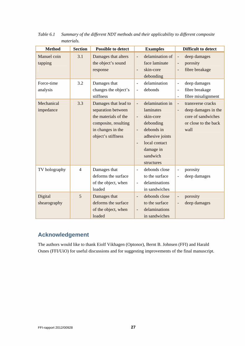
In this report, three non-destructive inspection methods for analysis of composite materials have
been discussed. The methods have been briefly described, types of damages detectable by the
methods have been discussed, and advantages and disadvantages have been listed. A comparison
between the methods has also been included. The main focus has been on composite materials. A
summary of the methods, as well as their applicability to detect various damages for composite
materials, is shown in Table 6.1.
Note that it is not intended in this survey to cover all aspects of the methods or all techniques
available. Still, the report should give a relatively good introduction to the methods described.
FFI-rapport 2012/00928 27
Table 6.1 Summary of the different NDT methods and their applicability to different composite
materials.
Method Section Possible to detect Examples Difficult to detect
Manuel coin
tapping
3.1 Damages that alters
the object’s sound
response
- delamination of
face laminate
- skin-core
debonding
- deep damages
- porosity
- fibre breakage
Force-time
analysis
3.2 Damages that
changes the object’s
stiffness
- delamination
- debonds
- deep damages
- fibre breakage
- fibre misalignment
Mechanical
impedance
3.3 Damages that lead to
separation between
the materials of the
composite, resulting
in changes in the
object’s stiffness
- delamination in
laminates
- skin-core
debonding
- debonds in
adhesive joints
- local contact
damage in
sandwich
structures
- transverse cracks
- deep damages in the
core of sandwiches
or close to the back
wall
TV holography 4 Damages that
deforms the surface
of the object, when
loaded
- debonds close
to the surface
- delaminations
in sandwiches
- porosity
- deep damages
Digital
shearography
5 Damages that
deforms the surface
of the object, when
loaded
- debonds close
to the surface
- delaminations
in sandwiches
- porosity
- deep damages
Acknowledgement
The authors would like to thank Eiolf Vikhagen (Optonor), Bernt B. Johnsen (FFI) and Harald
Osnes (FFI/UiO) for useful discussions and for suggesting improvements of the final manuscript.

FFI-rapport 2012/00928 29
Appendix A Additional sources
A.1 Links
The following list provides some relevant links to sites discussing/describing non-destructive
testing methods:
http://www.rnde.org/
http://www.asnt.org/
http://www.ndt-ed.org
http://www.netcomposites.com
A.2 Conferences
www.etech-ndt5.uoi.gr
http://www.ndt.net

30 FFI-rapport 2012/00928
References
[1] Vikhagen E., "TV-holografi og shearografi i NDT, 2 dagers kurs," Optonor, 2011.
[2] Forsyth D.S., "Non-destructive testing for corrosion," in Corrosion Fatigue and
Environmentally Assisted Cracking in Aging Military Vehicles (RTO-AG-AVT-140)
NATO RTO AVT, 2011.
[3] Kaiser H. and Karbhari V.M., "Quality and monitoring of structural rehabilitation
measures, Part 2: Review and assessment of non-destructive testing (NDT)
techniques,"2002.
[4] Adams R.D. and Cawley P., "A reveiw of defect types and nondestructive testing
techniques for composites and bonded joints," NDT International, vol. 21, no. 4, pp. 208-
222, 1988.
[5] Cawley P. and Adams R.D., "The mechanics of the coin-tap method of non-destructive
testing," Journal of Sound and Vibration, vol. 122, no. 2, pp. 299-316, 1988.
[6] "In-service inpection/repair manual," Thales JP3.23 - Inspection and Repair of Sandwich
Structures in Naval Ships,saNDI, D1.7.2, 2004.
[7] Hellier C.J., Handbook of nondestructive evaluation McGraw-Hill, 2001.
[8] Nelligan T. and Kass D., "Intro to Ultrasonic Phased Array," www.olympus-
ims.com/en/ultrasonics/intro-to-pa/, 2011.
[9] Cawley P., "The impedance method of non-destructive inspection," NDT International,
vol. 17, no. 2, pp. 59-65, 1984.
[10] Hung Y.Y., "Digital shearography versus TV-holography for non-destructive evaluation,"
Optics and Lasers in Engineering, vol. 26, pp. 421-436, 1997.
[11] Menner Ph., Gerhard H., and Busse G., "Lockin-interferometry: Principle and
applications in NDE," The 10th International Confernce of the Slovenian Society fir Non-
Destructive Testing, pp. 297-307, 2009.
[12] Vikhagen E., "Notat om TV holografi og shearografi," 2009.
[13] Ganesan A.R., "Holographic and laser speckle methods in non-destructive testing,"
Poceedings of the National Seminar & Exhibition on Non-Destructive Evaluation, 2009.
[14] Løkberg O.J. and Malmo J.T., "Detection of defects in composite materials by TV
holography," Non-destructive testing international, vol. 21, no. 4, pp. 223-228, 1988.
[15] Hung M.Y.Y., Shang H.M., and Yang L., "Unified approach for holography and
shearography in surface deformation measurement and nondestructive testing," Optical
Engineering, vol. 42, no. 5, pp. 1197-1207, 2003.
[16] Mutnuri. B., "Thermal conductivity characterization of composite materials." College of
Engineering and Mineral Resources, Department of Mechanical Engineering, West
Virginia University, 2006.
FFI-rapport 2012/00928 31
[17] Mix P.E., Introduction to nondestructive testing: a training guide, 2 ed John Wiley &
Sons, 2005.
[18] Ibarra-Castanedo C., Genest M., Guibert S., Piau J.M., Maldague X.P.V., and Bendada
A., "Inspection of aerospace materials by pulsed thermography, lock-in thermography
and vibrothermography: A comparative study," SPIE - The international Society for
Optical Engineering, Thermosense XXIX, 2007.
[19] Wu D. and Busse G., "Lock-in thermography for nondestructive evaluation of materials,"
International Journal of Thermal Science (founded as Revue Générale de Thermique),
vol. 37, pp. 693-703, 1998.
[20] Wu D., Zweschper T., Salerno A., and Busse G., "Lock-in thermography for
nondestructive evaluation of aerospace structures," Proceedings of ECNDT 1998, 1998.
[21] Gerhard H. and Busse G., "Lockin-ESPI interferometric imaging for remote non-
destructive testing," NDT&E International, vol. 39, pp. 627-635, 2006.
[22] Cawley P., "Inspection of composites - current status and challenges," Proceedings of
ECNDT 2006, 2006.
[23] Marini R., Vaz M.A., Monteiro J., Chousal J.A., and Santos F., "Non-destructive testing
of composite sandwich panels using optical interferometric methods," Proceedings of the
2nd International Conference on Emerging Technologies in NDT, 1999.
[24] Schuth M., Vössing F., and Yang L., "Shearographic NDT-measuring systems in theory
and application (endoscope for nondestructive test)," 2nd International Symposium on
NDT in Aerospace, 2010.
[25] Diamanti K. and Soutis C., "Structural health monitoring techniques for aircraft
composite structures," Progress in Aerospace Science, vol. 46, pp. 342-352, 2010.
[26] Hung Y.Y. and H. P. Ho, "Shearography: An optical measurement technique and
applications," Materials Science and Engineering, vol. 49, pp. 61-87, 2005.
[27] Hung Y.Y., "Applications of digital shearography for testing of composite structures,"
Composites: Part B, vol. 30, pp. 765-733, 1999.
[28] Kim S.-G., "Polarization phase-shifting technique in shearographic system with a
Wollaston prism.," Journal of the Optical Society of Korea, vol. 8, no. 3, pp. 122-126,
2004.
[29] Schnars U. and Henrich R., "Applications of NDT methods on composite structures in
aerospace industry," Conference on Damage in Composite Materials, 2006.
[30] Zhang Y., Wang Z., and Guo G., "NDT of aeronautical materials by digital
shearography," European Conference on Non-Destructive Testing, 2010.