Embed Size (px)
Citation preview
1673
NON-DESTRUCTIVE TEST METHODS FOR MASONRY STRUCTURES
R.C.de Vekey PhD C.Chem DIC MRSC Masonry Construction Section, Structural Integrity Div i sion
Building Research Establishment, Watford, WD2 7JR
ABSTRACT
Non destructive test (NDT) methods appl icable to masonry structures are defined, classified and reviewed in the context of the the type of information required to suit different problems, which tests are appropriate to which application and when they should be used. Some of the more promising techniques are discussed at greater length in the light of current research at the Building Research Establ ishment .
I NTRODUCTI ON
In the purest sense a Non-destructive test (NDT) method is one which can be applied to a material or structure and which will give some information as to it's form, condition or properties without palpably affecting the materials or the structure in any way. Most of this class of tests are basedon some Oorm of electromagnetic or other radiation. Examples are sound transmission, vibration, radar, thermal transmission, X-rays, Gamma rays, el ectromagneti c i nteracti ons (metal detectors), el ectri cal conductivity, capacitance and electrochemical potential. Load/deflection testing within the elastic limit should also cause no damage . These are here classified as group 1 tests .
Secondly there are tests, classified as Group 2, which cause limited local damage to materials but do not prejudice the integrity of the s tructure in any way. Such tests are b ased on the removal of small sampl es , the infl iction of small amounts of non-visible local ised damage or the i nfl iction of local ised but reparabl e damage. Typical exampl es , in rough order of severity, are surface tests such as the Schmidt hammer and the pull-off test, sub surface tests such as i nternal fracture, the use of borescopes to inspect cavities, sampl ing for chemical analysis, the fl at jack, sam~ing whole units, in- situ use of the bond wrench, coring specimens and sawing out of small sections of wall s .
Any method which demands the install ation of temporary load path supports or causes permanent deformation to 'a structural element goes beyond this philosophy.
1674
Why NDT for masonry
The application of such tests to masonry is generally to provide information on the characteristics of both new and old built structures. Data may be required on existing structures, particularly those predating the appl ication of any design codes or regulations, for many reasons such as: 1) It is intended to change the use and/or loadings from those curren~y applied and a design check is required. eg floor loading increased; storey to be added. 2) The loading on a structure has changed due to changing external circumstances and a safety check is required. eg increased vehicle weights on bridges and tunnels; an adjacent part of a terrace structure has been demolished. 3) The exposure of a structure has been altered. eg windscreening features have been removed or the level of atmospheric or aqueous polutants has increased. 4) It has been discovered during or after construction of a building that the materials, components or workmanship are not to the design specification and information is required to check the new design situation and decide whether any remedial action is necessary. 5) There are signs of distress or deterioration in a wall and it is neces~ary to diagnose the reason so that appropriate remedial action can be taken. 6) There has been a total collapse or failure and the reason is sought. 7) There are hidden features which must be located, sized, confirmed present or their condition assessed.
What data is required
Typically the sort of data required to deal with the problems may be generalised as (1) What is present? (2) Where is it? (3) What condition is it in? (4) How strong, wet, stiff etc. is it? The first three form a group to which some generalised test methods apply, the fourth, and sometimes the third, often require specialised equipment. Specific requirements for masonry are the compressive strength of units and mortar, their mutual bond strength, the state of stress, the stiffness, the content of any water-soluble compounds, the moisture content, the form, dimensions and condition of hidden features such as layers of finishing materials, piers, cavities, metal ties, straps, joist hangers and driven fixings. In cases where collapses occur data is also required on the loading state at the time ego the wind force.
When to use NDT
Even the cheapest tests tend to be expensive to carry out especially if the building is in a remote location thus a lot of care must be taken to select viable, cost effective and relevant tests . At the outset the specifier must have a clear idea of how the results are to be applied. If it is anticipated that a logical decision cannot be made on the basis of the tests, however unequivocal or decisive the resul t, then they shoul d not be carried out. If an effective structural repair or alteration can be carried out at lower than or equival ent cosf to a test to estab 1 i sh i t's necessi ty, then do not testo
Which tests are suitable
Currently very few of these test techniques have been fully investigated and evaluated for masonry materials and structures and there is a dearth of proven investigative techniques for deal ing with masonry probl ems. Even now the mos t common techni que i s to remove mortar by drill i ng and to eval uate by chemical analysis. There are almost no in-situ strength evauation
-
1675
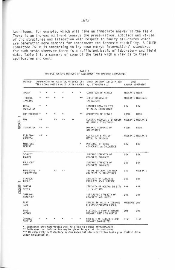
techniques, for example, which will give an immediate answer in the field . There is an increasing trend towards the preservation, adaption and re-use of old structures and litigation with respect to faulty structures which are generating more demands for assessment and forensic capability. A RILEM committee 76LUM is attempting to lay down embryo international standards for such tests wherever there is a sufficient basis of 1 aboratory and fiel d data. Table 1 is a summary of some of the tests with a view as to their ap~ ication and cost.
TABLE 1 NON-OESTRUCTlVE METHODS OF ASSESSMENT FOR MASONRY STRUCTURES
METHOD INFORMATlON ON POSITION/PRESENCE DF : OTHER INFORMATlON OBTAINED COST TlES REBAR VOIDS CRACKS LAYERS WATER ego STRENGTH etc. LABOUR EQUIPMENT
RADAR
THERMAL IMAGING
METAL DETECT ION
*
RAD IOGRAPHY *
c.. UPV ~ o ~ VIBRATlON
ELECTROCHEMICAL
MOISTURE METERS
SCHMIOT HAMMER
PULL-OFF TEST
BORESCOPE INSPECTlON
WINOSOR N PROBE
§; MORTAR o TESTS c:r:: c.!l
INTERNAL FRACTURE
FLAT JACK
BONO WRENCH
CORING/ CUTTING
**
**
**
** * *
*
** ** **
* * * *
* CONDITlON DF METALS
** EFFECTlVENESS DF INSULATION
MODERATE HIGH
MODERATE MODERATE
LlMITED DATA ON TYPE OF METAL (sometimes)
LOW LOW
** CONDITlON DF METALS HIGH HIGH
*
*
ELASTlC MOOULUS / STRENGTH MODERATE MOOERATE DF SIMPLE STRUCTURES
OYNAMIC RESPONSE OF STRUCTURES
HIGH HIGH
CORROS I ON ST ATE DF METAL IN MASONRY
MOOERATE MOOERATE
PRESENCE OF IONIC COMPOUNOS eg CHLORlDES
LOW
SURFACE STRENGTH OF LOW CONCRE TE PROOUCTS
SURFACE STRENGTH DF LOW CONCRETE PROOUCTS
VI SUAL INFORMATlON FROM LOW CAVITIES IN STRUCTURES
STRENGTH OF CONCRETE LOW PROOUCTS NEAR SURFACE
STRENGTH DF MORTAR IN-SlTU *** ie IN JOINTS
SUBSURF ACE STRENGTH DF LOW CONCRETE ANO UNITS
LOW
LOW
LOW
MOOERATE
LOW
***
LOW
STRESS IN WALLS + COLUMNS MOOERATE LOW ELAST IC/STRENGTH PROPS.
FLEXURAL & BONn STRENGTH MASONRY UNITS TO MORTAR
STRENGTH OF CONCRETE ANO MASONRY COMPOSITES
LOW LOW
HIGH HIGH
* Indicates that information will be given in normal circumstances ** Indicates that information may be given in special circumstances *** No compl etely satisfactory system known but pin penetration tests give 1 imited data. Under ill/estigation.
1676
DISCUSSION Df INDIVIDUAl GROUP 1 TESTS
Radar
There has been interest in the possib1 e app1 ication of radar/mi'crowaves to investigate buil ding material s since their deve10pment during the war. BRE research was carried out in the 1950s and 60s on i t's use for determination of moisture content of wa11s [1,2,3] . At the time the power and sensitiv~ty 1 imitations prevented the use of ref1ected radar. Transmitted radiation a1 though very wide1y app1 ied in industrial moisture contro1 is not very satisfactory for use on bui1dings where co-ordination of transmitter and receiver are difficu1t or impossib1e (eg ce11ar wa11s) . Diss~ved sa1ts a1so 1ead to variabi1ity. Recent advances in the solid state transmitter/receivers, antennae, and signa1 processing software have made one-side access refiected radar into a potenti~ly powerfu1 diagnostic too1 for civil engineering structures and bui1dings [4 , 5,6,7] . It is potenti~ly very versatil e because it gives information about most features of interest. Its versati1ity is a1so it's achilles hee1 in that so much information is returned that the observer is sometimes not ab1e to di scrimi nate .
The princip1e of operation is that a timed radar pulse is transmitted and the time of fiight (equiva1ent to depth) and intensity (equiva1ent to the size and character of the discontinuity) of refiections are recorded. The same effect can be achieved by using frequency modu1ated continuous waves (FMCW) and comparing the outgoing and return signa1s. By scanning the transmitter head (antenna) in a 1ine or plane a two or three dimensional image can be bui1 t up of what 1 ies be10w a surface . Refi ection occursat any significant boundary between material s hav ing different die1 ectric constants.
In masonry 1 ike1y boundaries are the interfaces in a wall ie between p1aster or dry1ining and masonry, between masonry and air or insu1ated cavities, voids in masonry units ego frogs or 1 arge voids in holl ow ware, between dry masonry and wet masonry eg either side of a dpm. Additiona11y metal s give a signa1 so ties, straps, fixings, metal dpms and any reinforcement may be 10cated .
The techni que has been tri ed on a typi cal UK cav ity wall and i t gave information about the thickness of the units and the width of the cavity p1us accurate information on the position of the wa11ties. In this tentative experiment there was a 25% error rate in identifying the tie type but this wou1 d be expected to improve as more experience i s gained and as the equipment is optimised to a more suitab1e wave1ength range . A new1y bui1t (around 2week old) section of w~l was sti11 sufficien~y damp to prev ent any measurements from b ei ng made i nd i cati ng that prob 1 ems wou1 d be encountered in dea1 ing with very wet wa11s. Experience gained on concrete has shown that information on the position of voids and reinforcement can be obtained .
Infra red thermography (IRT)
Infra red thermography is a technique for Observing the emission of heat from objects. It has a many uses in medicine and industry. Pa1jak [8] suggested that the technique cou1d be used to observe heat 1eakage from wa11s of bui1dings and it is now an accepted method for checking the therma1 performance of bui1dings [9] .
1677
The basic supposition under1ying the app1ication of this technique for w~l tie detection is that there co~d be sufficient therm~ transmission via a proper1y bedded intact wa11 tie to cause a detectab1e increase in the temperature of the outside face of the wa11 . Obvious1y any fau1ty workmanship which reduces or e1 iminates the embedment of the tie and any 1055 of section of the tie due to corrosion is 1ike1y to reduce the amount of heat transmitted. Other factors which might affect performance are the metal cross section of the tie , the conductivity of the units and mortar, the conductivity of the cavity (air or insu1ated) and the difference in temperature between the two faces . The advantage of the method over e1ectromagnetic metal detectors is that it may be possib1e to survey 1arge areas and get some data on whether the ties are insta11ed correct1y, whether they are of the correct specification and whether they are sti11 in good condition ie uncorroded.
In the modern form the equipment consists of an infra-red sensitive video camera capab1e, in the best circumssances, of detecting surface temperature differences of the order of 1 C within the scanned image area.
The experimental investigations have been carried out on a fair1y typica1 brick/brick cavity wall buil t of frogged common semi-dry-pressed units. To give experimental variety, a mixture of heavy vertical twist ties and 1 ight wire butterf1y ties were used and a few ties have been severed to simu1ate corrosion damage. The cavity is insu1ated over part of it's area with bead po1ystyrene. The current experimental procedure is to heat one face of the w~l using a hot p1ate pressed against the wa11 face and maintained in p1 ace overnight to estab1 ish an equi1 ibrium heat f1 ow condition. In the morning theopposite face of the wa11 is scanned with the IRT camera. The IR picture generated by the camera is in monochrome with a grey sca1e from b1ack (low emission) to white (high emission). The brick wa11 appears as a faint grid because the mortar has a higher conductivity than the bricks with the tie positions as brighter spots in the grid .
Resu1ts to date indicate that wi th a f i11ed cavity it isopossib1e to detect both types of ties at a temperature differentba1 of 50 C with the equ i pment avail ab1 e. At a reduced differentia1 of 46 C. it becomes difficu1 t to detect butterf1y ties.
With these requirements and the cgrrent heat i ng pane1s which can achieve a surface temperature of 50-60 C. it is necessary to work on coo1 mornings preferab1y at an externa1 temperature be10w 5 C. The performance in the current programme is 1imited by the sensitivity of the IRT unit in use. Future generations of IRT cameras and associated signa1-processing software shou1d be capab1e of higher discrimination a~d cou1d a110w successfu1 detection using the temperature difference between a norma11y heated bui1ding and the exterior on a coo1 day.
Metal detectors
These devices depend on the interaction between a coi1 or coi1s carrying an a1ternating vo1tage and conducting or ferromagnetic (or both) materia1s . Various princip1es are uti1ised inc1uding the effect of ferromagnetic material 5, eg stee1s, in increasing the inductance and impedance of the coi1/s and the effect of eddy currents induced in conductors, eg various non-ferrous metal 5, in 10ading the coi1/s. The geometry of the coi1 can be varied to contro1 the distance range over which they work and some, such as
-
1678
the induction balance and the VLF phase angle systems, can be tuned to give information about the type of metal present under well defined circumstances . Further information is given in Reference [10J. Their main problem is that most types are activated by ferritic steel and other ferromagnetic materials and they can be confused by the presence of impurities in the masonry units or the mortar. They are used, widely, for locating wall ties, other metallic fixings and reinforcement in masonry walls and, where calibrated specially, for giving information on depth of cover and diameter of reinforcement.
Radiography
The principle used is the same as that used for medical radiography in that a beam of high energy radiation generated by electrical means or from decay of unstable isotopes is passed through the structure and the signal is detected on the remo te face photographically or by scanned tranducers or arrays of transducers. Information is derived about the presence, position and size of objects having a different absorption characteristic to the main el ement. In masonry it can be used to investigate metal fix ings and voids. The main drawhacks are the requirement for access to two sides, and the precautfons needed to protect the public from the radiation. The method is also fairly expensive and slow but can give quite precise information about position of buried metal where critical. Some idea of the sort of appl ications possible can be seen in papers by Forrester [llJ and Tassios and Oeconomou [12J.
Ul trasonic pul se velocity (UPV)
The vel ocity of ul trasonic pul ses is dependant on nature of the sol id material, particularly the Youngs modulus and damping factor and the distribution of voids or pores which 1 engthen the effective path through sol id material. Thus qual itative rel ationships can be establ ished between factors such as the strength/stiffness of wall materials and the UPV. There is insufficient data currently avail abl e for absol ute determination of masonry characteristics from UPV measurements but the technique can be used to give comparitive data for simple geometries ego fully versus poorly b edded uni ts or low versus hi gh cement content mortar in pl ai n wall s. Work i s in progress to try to estab 1 i sh a full er data base and improve understanding of this application [13J.
Vibration
Two princi~es can be exploited, firstly the same as are applied for UPV but in a lower frequency range and secondly the analysis of the resonant frequencies of structures to give information on the stiffness and edge restaints. Neither principle has been developed significan~y for masonry structures although crude impact activated tests have been reported for checking tie action in gable walls.
1679
DISCUSSION OF INDIVIDUAL GROUP 2 TESTS
Shlli dt hanner
This is a well known technique which gives some measure of the surface hardness of materials by measuring the absorption of energy from a cal ibrated hammer bl ow. The technique is covered in a book by Malhotra [14]. There is no reason why the technique shouldn't be applied to concrete blocks and possibly to bricks but there is 1 ittl e available data.
Windsor prooe
Thi s i s an Ameri can devel opment b ased on fi ri ng a pi n i nto the, surface of a material using a fixed explosive charge and measuring the depth of enbedment. Inevitably the method is sensitive to the hardness of the aggregate in concrete material s and must have a separate cal ibration curve for each type . It' s use for concrete testi ng has been rev i ewed comparitively by Keiller[15] andin [14]. A similar technique, scaled down , has b een tri ed as a test for morta r b ut gave unrel i ab 1 e resul ts wi th aerated mortars in BRE tests and was abandoned. No specific calibration data is avail abl e for masonry material s .
Internal fracture test
This is an adaption of the 'pull-out', test to allow in-situ use. The principle of the test is that a re-entrant object is cast or fixed into the material and then pulled out using a standard diameter reaction ring and a force measuring device, typically a torque wrench .. The subsurface tensile strengh is measured by the force required to separate a cone of material from the main body. The BRE version employs an expansion anchor in a cyl indrical hol e and can thus be used for in -situ tests on ex isting structures. Currently there is only a full cal ibration data-base for concrete cube strength [16] but work is in progress to try to extend the technique to masonry material s by establ ishing cal ibration curves for blocks and bricks. Initial results indicate that the method will work for the denser and stronger concrete blocks with a new cal ibration curve and may be adaptable for testing bricks. Low density units can not be tested satisfactorily with the original test geometry. The method has been rev i ewed by Keill er [15] and Bungey [17] who proposed an al ternativ'e 1 oadi ng system.
Bond wrench
This is a simple lever test for measuring the bond strength between a pair of units and mortar in a wall . Firstly the brick must be isol ated by removing units from above and cutting away the perpends then a lever is clamped on and the moment required to cause fiexural failure of the brick/mortar bond is measured. The technique was researched by Hughes and Zsembary [18] and is now the subject of an ASTM standard [19] and a draft RILEM method. The technique was originally intended mainly for research and qual ity control of bond in masonry but Lovegrove [20] has discussed it ' s use for in-situ tests.
Fl at jack
A fiat jack is a thin diaphragm jack formed Jrom two sheets of metal welded at their edges. Jacking action is obtained by pumping hydraulic fluid into
-
-
1680
the jack. Because of the restraint from the edges and the geometry, each jack has to be individually calibrated in terms of pressure versus stress using a specimen with a stress field imposed by a test machine. A single jack can then be inserted in a strain-gauged slot cut in a structural element and the stress can be assessed when the strain state has been restored to the level existing before the slot was cut. Pairs of such jacks have been used to assess the elastic modulus and occasionally the strength of the masonry between them. Much of the development has been carried out in Italy for assessment of Roman masonry by Rossi [21J.
Moi sture Eters
This is too wide a topic to cover in any depth here. Both radar/microwave and other techniques such as conductance and capacitance have been used.
Optical prooes
Al so known as 'Borescopes' and 'Endoscopes', they were developed for seeing inside body cavities but are widely used for examining cavities in buildings . They are very useful for examining air cavities but of little use where the structural cav i ty i s fi" ed with i nsul ant.
ACKNOWLEDGEMENTS
The work described has been carried out as part of the research programme of the Building Research Establishment of the Department of the Environment and this paper is published by permission of the Director.
REFERENCES
1. A.Watson, The non-destructive measurement of water content by the microwave absorption method. CIB Bulletin 1960, 3 pp15-16.
2. Boot, A.R., Watson, A., Application of centrimetric radio waves in non-destructive testing, ASTM/RILEM symposium on application of advanced and nuclear physics to testing materials, 1964, ASTM SPT No.3?3.
3. Watson, A., Measurement of moisture content in.some structures and material s by microwave absorption, Proo . of RILEM/CIB symposium on moisture probl ems i!:!. buil dings 1965, 2, pp 6--::s.-- - -
4. Cl emena, G.G . , Eval uation of overl aid bridge decks with ground-penetration radar, Virginia Dept.of highways and transportation , 1982, Richmond PB 82 221839 . -
5. Botros,A.Z., Olver,A . D. Cuthbert,L.G. Farmer,G.A . , Microwave detection of hi dden objects in wall s, El ectroni cs 1 etters, 1984, 20, pp824-825.
6. Transbarger,O., FM radar for inspecting brick and concrete tunnel s , Material s Eval uation, 1985, 43, 10, pp1254-1261.
1681
7. Carr, A. G. , Cuthbert, L.G., Liau,T-F . , Signal processing techniques for short-range radars applied the detection of hidden objects, Proc. 7th European Conf. on Electrotechnics: EURCON 86, Paris, 1986.
8. Pal jak , I., Infrared Thermography appl i ed to testi ng of ex ternal wall s, Materiaux et Construction, 1971, 4, pp247-251.
9. Hart,J., The use of thermography in the performance testing of buil dings, Chapter in book ' Appl ications of Thermal Imaging' to be published 1988, Adam Hilger. --
10 . Metal Oetection, Feature article in Practical Wireless, 1979, January, pp31-42 .
11. Forrester,J.A., Gamma radiography of concrete, Conf .on Non-destructive testing of concrete and timber, Institution of Civil Engrs. UK.
12. Tassios, T., Oeconomou, Ch., A contribution to the Gamma radiography of reinforced concrete structures, Materiaux et Structures, 1971, 4, pp101-106. --
13. Hobbs, B., Wright, S.J., An assessment of ultrasonic tesing for structural masonry, Proc. BMS. 1st Intl .Masonry Conf. 1986, (to be pub)
14) Malhotra,V.M., Testing Hardened Concrete : non-destructive methods. American Concrete Institute Monograph No.9, 1976.
15. Keiller,A.P., An investigation of test methods for the assessment of strength of in-situ concrete, Proc.In~ .Conf.on non-destuctive testing, Nov. 1983, pp45-49 .
16. Chabowski ,A.J., Bryden-Smith , O.W., Internal fracture testing of in-situ concrete: a method of assessing compressive strength, Building Research Establishment IP22/80, 1980 .
17. Bungey,J .H., An appraisal of pull-out methods of testing concrete, Proc.Intl.Conf.on non-destuctive testing, London, Nov. 1983, pp12-21.
18. Hughes, O.H., and Zsembary, S., A method of determining the flexural bond strength of brickwork at right angles to the bed joint, Proc . 2nd Canadian Masonry symposium, 1980. pp73-86
19. Standard method for Measurement of Masonry Flexural Bond strength. ASTM Standard designation C1072-86, 1986
20. Lovegrove,R., Testing the flexural resistance of masonry by bond wrench, compared with BS5628 wallettes, Proc.Brit.Masonry Society symposium on masonry testing, Stoke on Trent, 1987, To be published in Masonry In~., 1988.
21. Rossi,P.P., Analysis of mechanical characteristics of brick masonry tested by means of non-destructive in-situ tests, Proc . 6th Intl.Brick Masonry Conf. 1982.