Embed Size (px)
Citation preview

Non Destructive Evaluation by Time of Flight Diffraction Method Mechanical Applications
B. BOSSUAT, H WALASZEK ,J.F.FLAVENOT. CETIM , Senlis, France
Abstract. The TOFD (time of flight diffraction method) which consists in an ultrasonic method for detection and dimensioning the discontinuities in the mechanical components, is more and more present in the industry. In some cases, the question of opportunity of using TOFD instead of X ray testing is discussed. This paper gives information about the interest and the limitations of the method, and its position in relation with X ray testing. Finally, applications of this method for mechanical engineering are described.
1. Introduction
Method still often ignored, the TOFD is a new process of ultrasonic control. The recent studies concerning this technique showed its effectiveness and its speed, and its competitiveness compared to radiography, without the disadvantages of the ionizing radiations. It is applied today in fields of control of the welded joints, but not only. In NDT community, the method is not yet known of all, and yet, in a few seconds, it allows the inspection of one meter welding on 50 mm thickness! A rather significant data when one knows that between the installation and measurements, other NDE methods require until several hours. Moreover, measurements are given in millimetres, detection does not depend on the orientation of the defect, and one can use it at high temperatures (up to 250°C). This method: the T.O.F.D. an acronym for Time of flight diffraction. Control TOFD has been increasingly popular, in fact, for these last years, more particularly in the laboratories and companies having a high level of expertise and which seek an advantageous alternative to the methods of non destructive testing (NDT) already existing. The strong probability of detection and especially the measuring accuracy of depth of the indications are there obviously for much. When the limits of the TOFD are reached, the traditional method of ultrasonics inspection can come in complement. The applicability is already rich: nuclear power with petrochemistry while passing by boiler making: for forgings, rolled, or of the pipes; one can use it within the framework of the quality control during the manufacture of engines, die spherical tanks, or of periodic inspections for the maintenance actions. The precise determination of the size of the defects makes it possible to follow their evolution well. But before going further in the possibilities than does the technique offers, how does it work?
2. Principles of Ultrasonic Time of Flight Inspection
The TOFD is a method of ultrasonics inspection. More precisely, an examination exploiting ultrasonic diffraction for detection. It highlights the signals diffracted by discontinuities in material of the controlled part (Fig. 1). One measures, in fact, travel time a contrario, where it is the quantity of returned energy which is commonly exploited. The principal difference
ECNDT 2006 - Poster 212
1
with a traditional method by ultrasounds lies in its possibility of detection of signals of low amplitudes of refraction rather than of the signals of great amplitudes considered. This detection allows a precise measurement of position and size of the defects, thanks to the current capacities of imagery (B or Dscan). The material necessary: two translators, one transmitting the other receiver, a connection, a device of sweeping, and a terminal carrying out the emission, the reception and the acquisition of the data. The technique, in the field of application of the control of the welded joints, grows thanks to the rise of digitized electronic equipment which allows the storage of all ultrasonic information and the cartographies of the detected indications. With this intention, one uses two separate and interdependent sensors, placed at the centre of the zone to control. They are strongly damped and of large aperture. They generate generally tilted longitudinal waves of the same frequency and under the same angle of refraction. The distance separating them depends on the angle of refraction, the thickness or the zone of the part to be controlled. The frequencies of use are about 1 to 15 MHz according to the matter to be inspected and the thickness of the part. As in conventional ultrasonics inspection, the major part of the emitted signal is absorbed by the matter, or is reflected by possible defects. But the part of the weak signal diffracted on a defect is captured and treated. This made of the TOFD a control more reproducible than traditional ultrasonic controls, because of the recording of the response of material in any point. It is thus possible to digitize and represent coast at coast each signal gross called A.scan, in the form of a called cartographic image Bscan. It represents in X-coordinate the displacement of the sensors, and in ordinate, the depth of the part. First Bscan, representing a displacement parallel with the welding, and thus normal with the beam of the sensors is used to detect the defects. Thus, second Bscan representing a displacement through the welding, and thus in the direction of the beam then makes it possible to dimension the detected defect. The advantage of this representation is that this image makes it possible to the controller to directly visualize and to be able to easily include/understand precise dimensional information of the image creates. We now will present examples of application which implement the interest of methodology.
Fig 1: principle of TOFD ultrasonic inspection
E : ultrasonic transmitter transducer, R : ultrasonic receiver transducer 1 : lateral wave , 2 :wave diffracted by the upper edge of the discontinuity 3 : wave diffracted by the lower edge of the discontinuity, 4 backwall echoe
2

3. Application to the Control of the Weldings
3.1. Application to the control of valve in the course of manufacture
The method most usually used for control of welded joints, such as for example below for this mechanical component, a body of valve (Fig. 2), is the radiography, which requires measurements of protection against radiation, and an access on the two sides of the component. On the other hand, in ultrasounds TOFD, the installation of two sensors is enough, separate and interdependent in the centre of the zone to be controlled generating tilted longitudinal waves (Fig. 3). The first received signal is the side wave which is just propagated below the surface of the part to control. In the absence of discontinuities, the second signal received by the receiver is the basic echo. These two signals are used as reference. Any signal generated by discontinuities of material will appear between them.
Figure 2: Tofd weld inspection on valve Figure 3: Tofd transducers for welding inspection The result of control is given in the form of an image on which are juxtaposed in the form of vertical lines the diffracted Ascan echoes. The amplitudes are represented in level of gray. The juxtaposition of Ascan acquisitions makes it possible to obtain an overall picture of the acoustic response of the interior of the component (figure 4). The analysis of ultrasonic times of flight (time of flight) enables to position and dimension discontinuities which diffract the ultrasounds. One gave hereafter the representation of the type A obtained in the presence of an indication by limiting to the interval “side wave - basic echo”, as well as the Bscan image created. In X-coordinate, the position of the mechanism of sweeping. In ordinate, the amplitude of the ultrasonic signals according to time for the interval corresponding to the thickness of the part (representation of the type A). One uses the high frequency signals (not rectified and smoothed) digitized. The lateral wave is visualized by a horizontal line (or series of horizontal lines) in top of the recording. The basic echo is also visualized by a horizontal line (or series of horizontal lines). The diffracting elements (edge of defect) seem rectilinear or curved lines. One carries out then a sweating on the part to check in this case present the validity of detection at the good depth of the defect.
3

Figure 4 : Bscan image of valve weld Figure 5 : the defect detected by TOFD is
made evident by grinding and dye penetrant inspection
3.2 Application to pressure vessels equipment testing A trial run was carried out by CETIM on constructed boilers components, with for objectives comparing the performances of ultrasonic method TOFD with that of the radiography, often considered as method of reference, because of the generalization of its application. Methodology is characterized by a good portability. All the indications detected by radiography were also detected by TOFD (Fig. 6, 7, 8, 9) Tofd image produced x-ray image
Figure 6 : lack of penetration detection
4

Tofd image produced x-ray image
Figure 7 : detection of a surface crack, located near the seam Tofd image produced x-ray image
Figure 8: detection of a lack of fusion, located near the seam
Figure 9 : Toft control operated on site : producing an « ultrasonic film of the weld »
5

4. Application to Crack Propagation Monitoring On a Mechanical Component
The great degree of reproducibility of ultrasonic method TOFD makes it possible to dimension, then to follow the evolution of cracking on mechanical component. Thus, CETIM uses method TOFD now to ensure the monitoring of the progression of the cracks during the fatigue tests carried out in its workshops.
4.1. Control and monitoring of crack propagation
It is at the request of industrial customers that CETIM “manufactured” of the fatigue cracks gauged in a rotating shaft [2]. The machine element of a diameter of 70 mm was subjected to fatigue tests in rotational bending. The stake thus was to create a crack with a geometry defined in advance. To follow the good propagation of this defect, method TODF was implemented. This control allows, inter alia, thanks to the diffraction of the ultrasonic waves at the ends of the indication - the crack - a measurement depth in millimetres, with some tenth close to the defect. The shaft assembled on a test bench turns to 1.500 tr/min. The bending stress is applied by four rollers assembled on the sensor of effort. This last is fixed at the end of the stem of the hydraulic actuating cylinder being able to make a maximum effort of 100 kN. The crack initiation of tiredness is caused by a 1,5 depth mm right notch machined by electro erosion in the middle of the tree. Using method TOFD, the depth of the crack is controlled progressively. A particular assembly is carried out so that the ultrasonic sensors can engage measurements on a lathe of shaft. For this purpose, the speed of the shaft is decreased to 2 tr/min. The effort applied at this time precise is 5 kN: the crack opens thus at the time of the passage to the maximum constraint. To clearly start the crack at the bottom of the notch, the test starts with a constant effort applied to 35 kN. What is equivalent to a nominal constraint in the ardre of about 250 Mpa. The started defect, one produces stages of load and a number of decreasing cycles. One thus keeps the control of the propagation of the crack. In constant amplitude, the propagation of the crack is accelerated in an exponential way (law of Paris). During the stages of constant amplitude, and during the rotation of the tree, concentricity is checked for an effort of 5 kN. If most of the tree is fissured, this concentricity (or arrow to the maximum of the constraint) increases. To supplement the test and to be ensured of the good behaviour of the unit, the displacement of the piston of the jack is controlled permanently. What makes it possible to detect, if necessary, a loss of rigidity in inflection, and thus, a progressive cracking of the tree? In addition, a periodic control of the propagation of the crack on the surface, on each side of the initial notch, using a magnifying glass or by sweating, is carried out and makes it possible to visualize the probable geometry of the defect throughout the test.
Figure 11: using method TOFD, the sensors ultrasonic * allow precise measurements depth of the cracks
Figure 10: the assembly of the test bench allowing to gauge the fatigue cracks on the rotating shaft
6

The recordings TOFD which show the progression of the defect of tiredness in the matter are given below of figure 18. One deals, with the number of “stereotypes” close, to elementary ultrasonic “film” of the life of the crack within the matter.
Figure 12 : fatigue crack propagation shown by Tofd method One gives below (figure 13 and 14), the setting compared to measurement TOFD with [the theoretical curve of cracking] and numbers it cycles of tiredness undergone by the part. The distribution of cracking according to the angular position on the tree is given in figure 10.
Figure 13 : Tofd measurement of fatigue crack depth Figure 14 : scheme of cracked section
7

5. Application to Corrosion Monitoring
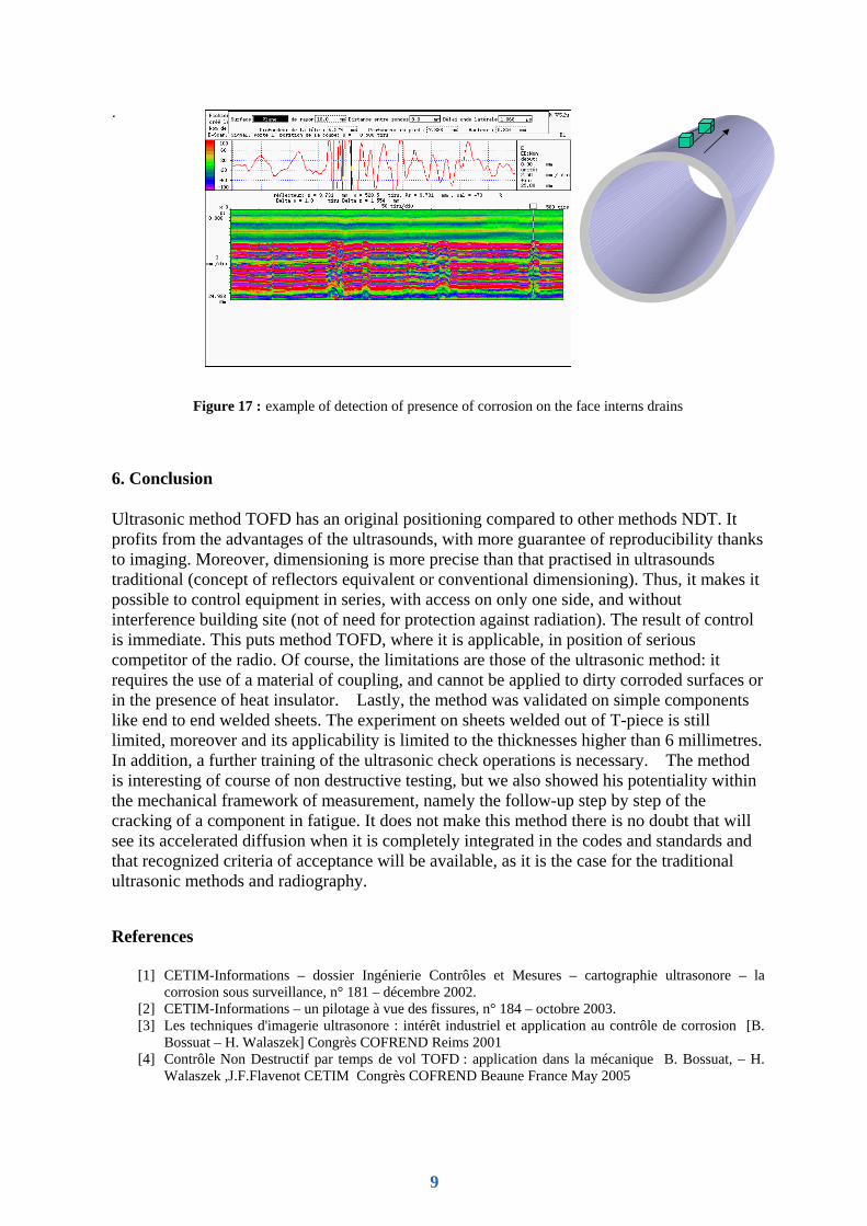
The Channel tunnel is 50 km long and consists of two independent tunnels which are cooled by a drain 400 mms in diameter. This drain extracts heat by natural convection, maintaining a temperature lain between 20 and 25°C. The cooling water is sent in exchangers of 50 Megawatts. The overall length of the drain is of 190 km. Small punctures of corrosion were detected at the time of maintenance action on the interior face of the drains. Following these discoveries, Eurotunnel asked for measurements of thickness. Conventional measurements thickness carried out pulsates echo of it are not applicable because the punctures give reflexions of low amplitude because of their weak surface. On the contrary, the TOFD proved adapted for the detection of the punctures and the measurement residual thickness of the drains.
Figure 15 : comparison of a control by TOFD for the search for punctures with the classical thickness measurement technique in mode pulse- echo
Special equipment was designed to carry out measurements on site (figure 16). A special sensor was adapted allowing the detection of punctures length lower than 100 µm. The equipment of control equipped “TOFD” gives an image (figure 7) residual thickness of the drains measures per meter of drain. The control of 50 zones over several weeks made it possible Eurotunnel to precisely know the state of corrosion of these drains and to program an adapted plan of maintenance
Figure 16 :Tofd equipment used to monitor the eventual corrosion on Transmanche Tunnel + cooling pipes
puncture
Tofd receiver transducerTofd emitter transducer
Incident beam Diffracted beam
Echographic ultrasonic probe
No réflection
8
.
Figure 17 : example of detection of presence of corrosion on the face interns drains
6. Conclusion
Ultrasonic method TOFD has an original positioning compared to other methods NDT. It profits from the advantages of the ultrasounds, with more guarantee of reproducibility thanks to imaging. Moreover, dimensioning is more precise than that practised in ultrasounds traditional (concept of reflectors equivalent or conventional dimensioning). Thus, it makes it possible to control equipment in series, with access on only one side, and without interference building site (not of need for protection against radiation). The result of control is immediate. This puts method TOFD, where it is applicable, in position of serious competitor of the radio. Of course, the limitations are those of the ultrasonic method: it requires the use of a material of coupling, and cannot be applied to dirty corroded surfaces or in the presence of heat insulator. Lastly, the method was validated on simple components like end to end welded sheets. The experiment on sheets welded out of T-piece is still limited, moreover and its applicability is limited to the thicknesses higher than 6 millimetres. In addition, a further training of the ultrasonic check operations is necessary. The method is interesting of course of non destructive testing, but we also showed his potentiality within the mechanical framework of measurement, namely the follow-up step by step of the cracking of a component in fatigue. It does not make this method there is no doubt that will see its accelerated diffusion when it is completely integrated in the codes and standards and that recognized criteria of acceptance will be available, as it is the case for the traditional ultrasonic methods and radiography.
References
[1] CETIM-Informations – dossier Ingénierie Contrôles et Mesures – cartographie ultrasonore – la corrosion sous surveillance, n° 181 – décembre 2002.
[2] CETIM-Informations – un pilotage à vue des fissures, n° 184 – octobre 2003. [3] Les techniques d'imagerie ultrasonore : intérêt industriel et application au contrôle de corrosion [B.
Bossuat – H. Walaszek] Congrès COFREND Reims 2001 [4] Contrôle Non Destructif par temps de vol TOFD : application dans la mécanique B. Bossuat, – H.
Walaszek ,J.F.Flavenot CETIM Congrès COFREND Beaune France May 2005
9