Embed Size (px)
Citation preview

NON DESTRUCTIVE AND MEDIUM DESTRUCTIVE ANALYSES ON AN EARLY 20th
CENTURY REINFORCED CONCRETE STRUCTURE: THE CASE STUDY OF THE VICTORY
MONUMENT IN BOLZANO
Michele Secco1
1CIRCe – Centro Interdipartimentale di Ricerca per lo Studio dei Materiali Cementizi e dei Leganti
Idraulici, Via Gradenigo, 6 – 35131 Padova
Elena Stievanin1*
, Francesca da Porto1, Claudio Modena
1, Gilberto Artioli
1, Claudio Mazzoli
2
2Dipartimento di Geoscienze, Via Gradenigo, 6 – 35131 Padova
* corresponding author: [email protected], Tel.: +39 049 8275560
Introduction
Patented by Joseph Monier in 1867, the reinforced concrete became a highly successful material during
the 20th
century, capable of satisfying the most challenging demands of designers and engineers.
However, the mechanical behavior of structures made with this material was not fully understood for a
long time, giving rise to a variety of structural problems of the buildings built in the first decades of the
20th
century. At the roots of the problem there was not only the empirical conception of the structural
calculations, but also the lack of development of standard concrete production technology and the poor
attention paid to the choice of raw materials and their mixing methodology. Furthermore, the problem of
reinforced concrete behavior to external chemical-physical degrading agents was not considered during
most of the 20th
century, due to the wrong assumption of “infinite durability” of this material.
Given the complexity of the material, a combined multidisciplinary approach, covering the fields of
materials science and engineering, is necessary to obtain a full mechanical and microstructural
characterization of reinforced concrete structures and, consequently, to plan and perform proper
interventions with adequate restoration materials for the rehabilitation of this modern heritage.
Historical background and architectural features of the monument
Designed by Marcello Piacentini in 1926 and built during the course of 1929, the Victory Monument is
nowadays considered a masterpiece of fascist architecture. Inspired by Roman triumphal arches, the
structure is 22 meters tall and 10 meters wide. The monument is conceived as a colonnade standing on a
large stairway podium, covering a subterranean crypt. The colonnade is constituted by fourteen multiple
columns, without capital, sustaining the triumphal arch. The structure stands on a concrete strip
foundation, lying on a flattened alluvial ground. The substructure of the podium is constituted by non-
reinforced concrete walls, sustaining a series of reinforced concrete slabs forming the stairway and a non-
reinforced concrete slab forming a central vault. The slabs of the stairway are limited by reinforced
concrete beams. The nucleus of the columns is also made by concrete, as well as the ceiling of the
monument, sustaining a series of bronze beams. The monument is covered by stone slabs of different
lithologic typologies, and decorated by sculptures and paintings made by famous fascist artists.
The building has showed clear structural problems since the first few years following the construction:
foundation failures caused the breaking of the floor slabs, and massive water infiltrations caused damage
not only to the stone coverings, but also to the concrete nucleus, with extensive fissurations of the
concrete slab sustaining the colonnade and of the architraves of the columns. Also, the sculptures and the
paintings were also heavily damaged by the water infiltrations.
A first restoration of the monument was carried out in 1991-1992 by the department of Cultural Heritage
of Verona, and was aimed at consolidating the reinforced concrete nucleus of the colonnade and the
bronze ceiling. The new restoration started in November 2009, under the supervision of the Italian
Ministry for Cultural Heritage. The analytical campaign described in this contribute was performed in
order to plan adequate structural improvements of the monument.
The conservation state of the structure
The preliminary visual inspection performed on the structure highlighted widespread degradation of the
materials, particularly severe on the reinforced concrete structural elements constituting the substructure
of the monument. Massive water infiltrations and high relative humidity excursions caused decalcification
and leaching events on the cementitious matrices of the conglomerates, with associated pop-out of the
inert fraction and superficial detachments and delaminations of the concrete covers (Figure 1a).

The slabs and the beams are characterized by the presence of wide areas showing total detachment of the
concrete cover, and the exposed rebars are widely oxidized, showing massive loss of section. It is also
possible to observe the presence of superficial concretions and efflorescences constituted by secondary
crystalline phases (Figure 1b). The concrete walls show marked superficial loss of cohesion, associated
with wide development of secondary mineralogical phases in concretions and efflorescences.
Figure 1: a) Conservation state of the concrete substructure; b) degradation phenomena on a concrete beam.
The analytical campaign
Visual inspection allowed identifying the most significant elements on which tests for the characterization
of the vertical and horizontal structures should be carried out. Several on site tests were planned and then
carried out to improve the level of knowledge. These investigations were planned to minimize
obtrusiveness on existing structures and to favour crosschecking of results among tests at different level
of invasiveness. Investigations were carried out with two complementary aims: obtaining informations
about mechanical properties of materials and studying their chemical-physical characteristics.
Presence, distribution and diameters of the reinforcement bars inside the cementitious conglomerate were
reconstructed through a non-destructive analytical approach, using an Hilti Ferroscan magnetic scanner.
The acquisition of the magnetic signal was performed using a 60x60 cm reference grid, with an internal
15x15 cm net, as indicated by the European Standard EN 12504-2. The data were stored on the internal
memory of the instrument and then elaborated through the dedicated Ferroscan software. The data were
then crosschecked performing localized scarifications of the concrete covering.
The compressive strength of the concrete elements was evaluated in-situ non-destructively through a
Schmidt Hammer [1]. The rebound indexes were measured following the prescriptions indicated by the
European Standard EN 12504-2, and the compression strength values were obtained by means of
correlation curves, provided with the instrument.
These non-destructive tests only delivered qualitative results, to be integrated by the data achieved
through medium destructive analyses performed in laboratory on representative samples.
Concrete samples were obtained by means of corings performed through a Hilti DD 130 water lubricated
core drill. Prior to perforation, the position of the structural elements with a low bending moment, shear
and axial force values was chosen and then a superficial scans by means of magnetic scanner were
performed, to avoid damage to the rebars. Moreover, on the basis of the dimensions of the structural
elements, hollow tips with different diameters were used, to limit the invasiveness of the sampling. More
in detail, a 95 mm hollow tip was used for the coring both of the concrete walls and the vaulted concrete
slab. The cores sampled on the walls were extracted at different heights, in horizontal direction. To
facilitate the sampling, the coring of the vaulted slab was performed at the extrados, avoiding the weakest
points of the structure and backfilled areas. The first coring was unsuccessful due to difficulties in the
extraction of the sample from the extrados, therefore a second coring was necessary. As regards the
coring of a representative beam, two hollow tips characterized by different diameters (95 mm and 75 mm)
were used, to avoid damage to the rebars, arranged with a reduced spacing. The first two corings were
performed at the extrados, while the third was performed laterally. For the coring of the stairway slab,
performed at the extrados, a 75 mm hollow tip was used.
Moreover, samples of detached concrete covering and superficial concretions and efflorescences were
collected. A scheme of sampling locations and denominations is reported in Figure 2 and Table 1.
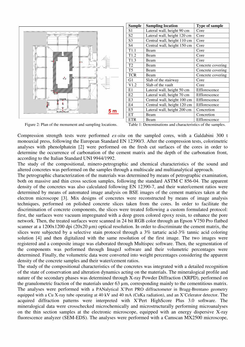
Sample Sampling location Type of sample
S1 Lateral wall, height 90 cm Core
S2 Lateral wall, height 120 cm Core
S3 Central wall, height 110 cm Core
S4 Central wall, height 150 cm Core
T1.1 Beam Core
T1.2 Beam Core
T1.3 Beam Core
T2 Beam Concrete covering
T5 Beam Concrete covering
TCR Beam Concrete covering
G1 Slab of the stairway Core
V1.2 Slab of the vault Core
E1 Lateral wall, height 50 cm Efflorescence
E2 Lateral wall, height 70 cm Efflorescence
E3 Central wall, height 100 cm Efflorescence
E4 Central wall, height 120 cm Efflorescence
E5 Lateral wall, height 200 cm Concretion
ET Beam Concretion
ETR Beam Efflorescence
Figure 2: Plan of the monument and sampling locations. Table 1: Denominations and characteristics of the samples.
Compression strength tests were performed ex-situ on the sampled cores, with a Galdabini 300 t
monoaxial press, following the European Standard EN 12390/3. After the compression tests, colorimetric
analyses with phenolphatein [2] were performed on the fresh cut surfaces of the cores in order to
determine the occurrence of carbonation of the cement matrix and the depth of the carbonation front,
according to the Italian Standard UNI 9944/1992.
The study of the compositional, minero-petrographic and chemical characteristics of the sound and
altered concretes was performed on the samples through a multiscale and multianalytical approach.
The petrographic characterization of the materials was determined by means of petrographic examination,
both on massive and thin cross section samples, following the standard ASTM C 856-04. The apparent
density of the concretes was also calculated following EN 12390-7, and their water/cement ratios were
determined by means of automated image analysis on BSE images of the cement matrices taken at the
electron microscope [3]. Mix designs of concretes were reconstructed by means of image analysis
techniques, performed on polished concrete slices taken from the cores. In order to facilitate the
discrimination of concrete components, the slices were treated following a custom formulated protocol:
first, the surfaces were vacuum impregnated with a deep green colored epoxy resin, to enhance the pore
network. Then, the treated surfaces were scanned in 24 bit RGB color through an Epson V750 Pro flatbed
scanner at a 1200x1200 dpi (20x20 µm) optical resolution. In order to discriminate the cement matrix, the
slices were subjected by a selective stain protocol through a 3% tartaric acid-3% tannic acid coloring
solution [4] and then digitalized with the same resolution of the first image. The two images were
registered and a composite image was elaborated through Multispec software. Then, the segmentation of
the components was performed through ImageJ software and their volumetric percentages were
determined. Finally, the volumetric data were converted into weight percentages considering the apparent
density of the concrete samples and their water/cement ratios.
The study of the compositional characteristics of the concretes was integrated with a detailed recognition
of the state of conservation and alteration dynamics acting on the materials. The mineralogical profile and
nature of the secondary phases was determined through X-ray Powder Diffraction (XRPD), performed on
the granulometric fraction of the materials under 63 µm, corresponding mainly to the cementitious matrix.
The analyses were performed with a PANalytical X’Pert PRO diffractometer in Bragg-Brentano geometry
equipped with a Cu X-ray tube operating at 40 kV and 40 mA (CuKa radiation), and an X’Celerator detector. The
acquired diffraction patterns were interpreted with X’Pert HighScore Plus 3.0 software. The
mineralogical data were crosschecked microchemically and microstructurally performing microanalyses
on the thin section samples at the electronic microscope, equipped with an energy dispersive X-ray
fluorescence analyzer (SEM-EDS). The analyses were performed with a Camscan MX2500 microscope,
equipped with LaB6 source and EDAX EDS system. The qualitative and semiquantitative analysis of the
fluorescence spectra was performed with SEMQuant Phizaf software.
Results
On site tests A first evaluation of the compressive strength of the concrete of the basement walls was performed using
data from the rebound strokes. Investigations were carried out on the lateral sample wall named S1. The
beats were made at different heights, as the concrete composition was extremely variable from point to
point. The values obtained and the corresponding value of compressive strength are shown in Table 2.
Identification h[m] Rebound index Compressive strenght [MPa]
0.90 16 16 24 18 19 15 16 16 16 20 17
1.20 19 24 20 22 22 20 26 20 20 24 21 Wall S1
1.70 25 30 26 20 24 28 28 25 25 22 25
Table 2: Results of the rebound hammer tests.
According to test results, it is possible to notice how the values of compressive strength vary widely with
the position of the beats. In particular, a decrease of mechanical properties towards the base of the wall
could be observed, making it possible to envisage problems of aggregate segregation related to an
inadequate jet vibration during the execution of the work.
Magnetic tests were carried out in correspondence of the beam bearing point at the extrados, to verify the
static scheme. The lack of upper reinforcement underlined the absence of a continuous static scheme of
the beam.
Magnetic tests on the stairway slab showed the presence of a reinforcement net of a 30x30 cm spacing,
constituted by bars with a diameter of 8 mm. The concrete covering is about 5 cm (Table 3).
The almost total lack of concrete covering in some areas of the beams allowed to reconstruct the
disposition and geometric characteristics of their reinforcement bars by means of localized scarifications
only. The beams have a typical T section due to the presence of the collaborating upper slab. The width of
the beams is 20 cm, and the height 35 cm. The reinforcement at the bottom of the section is constituted by
6 bars with a 14 mm diameter, while stirrups have a diameter of 8 mm and are placed with a spacing of 50
cm, not always regular. Generally, both longitudinal and transversal bars lost their cross section due to
massive corrosion favored by the environmental conditions and the loss of concrete covering. The
average span of the beams is 5 m, with a spacing of 1.35 m (Table 3).
Section Width (m) Height (m) Rebars Stirrups
Typical RC beam
0.25 0.35 6ø14 (at the bottom) ø8/50
Typical RC slab
- 0.10 ø8/ 30 (in both direction) -
Table 3: Geometrical characteristics of the structural elements.
Compression tests The cores were tested in laboratory to obtain compressive strength values. Due to the limited number of
samples, a more accurate mechanical characterization of the concrete elements was not possible.

Cores T1.1, T1.3, V1.2 and G1 (Table 4) are characterized by a height only slightly higher than the
diameter, so the compressive strength value was assumed equal to the cubic strength. The height of the
other cores (S1, S2, S3, S4) was double than the diameter, so the value of compressive strength was
assumed equal to the cylindrical strength and then converted to the corresponding cubic value.
Sample Diameter (cm) Height (cm) Area (cm2) Mass (Kg) Ultimate load (Kgf) Rck(MPa)
S 1 9.40 19.40 69.40 2.83 4700 8.00
S 2 9.40 19.70 69.40 2.94 5900 10.05
S 3 9.40 19.40 69.40 2.85 11000 18.73
S 4 9.40 19.60 69.40 2.93 3700 6.30
T 1.1 9.40 8.20 69.40 1.28 34200 48.34
T 1.3 9.40 10.50 69.40 1.63 34800 49.19
V 1.2 9.40 10.70 69.40 1.49 8300 11.73
G 1 7.40 7.00 43.01 0.66 17000 38.78
Table 4: Results of the compression tests on the concrete cores.
The cubic strength values, as showed in Table 4, highlight a clear difference in concrete quality between
the conglomerate used for the execution of the beams and the staiway slab and the one used for the walls
and the vaulted slab. It is possible to hypothesize that the beams and the stairway slab were made with a
mixture characterized by a better mix design, according to a more accurate execution.
Minero-petrographic characterisation of the conglomerates Petrographic and XRPD data were combined in order to attain a complete characterization of the
materials used in the concrete manufacture. Considering the analytical results, the concretes constituting
the structural elements of the monument can be divided in three main groups:
Concretes of the walls (Figure 3a-b). The materials are characterized by inadequate volumetric
proportions between inert fraction and cement matrix, with clear enrichment in fine aggregate. The
granulometric distribution of the aggregate is bimodal and far from the ideal Bolomey curve [5]. The
coarse aggregate is constituted by rounded natural gravel characterized by poor grading, with peaks of
distribution at 50 and 8 mm. Petrographically, felsic volcanic species are highly predominant, in
particular ignimbrites and rhyolites. A subordinate metamorphic fraction is also present, constituted by
quartzites, phyllites and amphibolites. The fine aggregate is constituted by rounded natural sand of the
same petrographic nature, with dimensions in the range of the medium sands. The nature of the inert
fraction is compatible continental deposits of the Talvera river [6], suggesting a local supply of the
aggregate. The cement matrix generally shows poor adhesion to the aggregate, and results highly
fractured. The hydration of the cement is almost total, as showed by the absence of reflexes of residual
clinker phases in the diffraction patterns of the finer fractions of the conglomerates. The overall porosity
is high, with clear prevalence of irregular entrapped air voids/water voids with medium dimensions of 5-7
mm over spherical submillimetric entrained air voids.
Concretes of the vaulted slab (Figure 3c-d). The materials are characterized by higher cement matrix
volumetric quantities with respect to the conglomerates of the walls, indicating higher cement dosages in
the original mix design. As regards the inert fraction, an enrichment in fine aggregate is still observable,
while the gravel fraction is highly subordinated. The granulometric distribution of the aggregate is
bimodal and far from the ideal Bolomey curve. The coarse aggregate is constituted by rounded natural
gravel characterized by medium grading, with a peak of distribution at 8 mm. The fine aggregate is
constituted by rounded natural sand with dimensions in the range of the medium sands. The petrographic
nature of the inert fraction is similar to the one observed for the aggregate of the concrete walls. The
cement matrix generally shows poor adhesion to the aggregate, and results highly fractured. A reduced
amount of residual unhydrated clinker grains is still present, as showed by the presence of traces of C2S,
C3A and C4AF in the finer fractions of the conglomerates. The overall porosity is low, with prevalence of
spherical submillimetric entrained air voids over irregular entrapped air voids/water voids with
millimetric dimensions.
Concretes of the stairway beams and slabs (Figure 3e-f). The conglomerates are characterized by
better volumetric proportions of the constituents with respect to the concretes of the other structural
elements, showing the highest cement contents. Still, an enrichment in fine aggregate is observable. The

granulometric distribution of the aggregate is bimodal and far from the ideal Bolomey curve. The coarse
aggregate is constituted by rounded natural gravel characterized by high grading, with a peak of
distribution at 7 mm. The fine aggregate is constituted by rounded natural sand with dimensions in the
range of the medium sands. The petrographic nature of the inert fraction is similar to the one observed for
the aggregate of the concrete walls and slabs. The cement matrix generally shows a good adhesion with
the aggregate, and results only slightly fractured. A significant amount of residual unhydrated clinker
grains is still present, as showed also by the presence of C2S, C3A and C4AF in the finer fractions of the
conglomerates. The overall porosity is low, with prevalence of spherical submillimetric entrained air
voids over irregular entrapped air voids/water voids with millimetric dimensions.
Figure 3: a, c, e) Samples S2, V1.2, T1.2, massive cross section (pore network highlighted in green); b, d,
f) samples S2, V1.2, T1.2, polarizing light micrographs, taken in cross polarized light.
Mix designs reconstruction A summary of the compositional characteristics and mix designs of the concretes is reported in Table 5.
Core
Apparent
Density
(g/cm3)
Total porosity
(% vol.)
Water/cement
ratio
Cement/aggregate
ratio
Cement
(kg/m3)
Gravel
(kg/m3)
Sand
(kg/m3)
Insoluble
residue (kg/m3)
S1 1.89 11.8 0.73 0.03 58.02 482.52 1317.69 2.31
S2 1.99 12.3 0.73 0.04 78.64 838.96 1033.34 3.03
S3 2.07 14.1 0.71 0.05 97.67 718.83 1207.55 7.45
S4 1.85 4.7 0.71 0.05 87.05 983.37 739.43 4.78
T1 1.89 4.7 0.61 0.11 178.25 546.04 1083.76 9.31
V1 1.77 4.7 0.81 0.10 155.15 367.09 1170.95 10.83
Table 5: summary of the compositional characteristics and mix designs of the concretes, as determined by image analysis.
The quantitative results are fully consistent with the qualitative observations performed through the
petrographic examinations. Generally the structural elements are made with lean concretes, with
cement/aggregate ratios under 0.15. Clear differentiations between the typology of concrete used for the
different structural elements are observable. The concretes of the lateral walls (cores S1 and S2) are
characterized by low cement contents and high water/cement ratios, and the sand fraction is highly
predominant. Differences in the mix designs between the two cores highlight the high heterogeneity of
the concrete, indicating inadequate homogenization of the fresh conglomerate. All these characteristics
justify the high porosity (over 10% of the overall volume) and the low mechanical strength. The
concretes of the central wall (cores S3 and S4) are characterized by higher cement contents and lower
water/cement ratios with respect to the concretes of the lateral walls, with higher gravel concentrations.
Also in this case, differences in the mix designs between the two cores highlight the high heterogeneity of

the concrete, indicating inadequate homogenization of the fresh conglomerate. This hypothesis is also
supported by the high differences in porosity values between the two samples.
The concrete of the vaulted slab is characterized by higher cement contents and water/cement ratios with
respect with the concrete of the walls, and the inert fraction is characterized by the lowest gravel
concentrations. The overall porosity is lower than the medium volumetric values of porosity observed for
the concrete walls, thus indicating a better compaction of the conglomerate at the fresh state.
The concrete constituting the stairway beams and slabs show the best compositional characteristics, with
the highest cement contents and cement/aggregate ratios and the lowest water/cement ratios. These
characteristics justify high mechanical strength. The low total porosity (4.7% of the overall volume)
indicates the good compaction of the conglomerate at the fresh state during the manufacturing of these
structural elements. The sand fraction is also in this case predominant over the gravel fraction.
Weathering phenomena The materials underwent massive carbonation of the cement matrix, due to the reaction between
portlandite and carbon dioxide from the atmosphere [7]. The degree of carbonation is differentiated
according to the typology and compositional characteristics of the concrete structural elements.
The colorimetric tests indicated a total carbonation of the concretes of the walls, while the concretes of
the slabs and the beams are totally carbonated in the first 4 cm only. The diffractometric analysis
confirmed the results of the colorimetric tests: the mineralogical profiles of the cement matrices of the
walls are constituted by predominant calcite, without residual amounts of portlandite (Figure 4a). The
diffractometric profiles of the beams and the slabs (Figure 4b) are constituted by predominant quartz,
whose presence is due to inadequate mechanical separation of the inert fraction from the cement matrix.
As regards the calcium-bearing phases, significant amounts of calcite are present, related to carbonation
processes. Also, it is possible to observe a progressive increase in portlandite concentrations moving
towards the inner cement matrices, indicating a permanence of the alkaline environment of the concrete.
The high calcite concentrations, especially in the concretes of the walls, are not only due to the
carbonation of the portlandite, but also to the formation of carbonate concretions in the pore network of
the materials after precipitation of calcium bicarbonate from the infiltrating waters and subsequent
conversion in calcium carbonate. This hypothesis is confirmed by the carbonate composition of the
superficial concretions sampled on the surfaces of the concretes (Figure 4c).
The XRPD results are fully consistent with the data from the SEM-EDS analyses. The cement matrices of
the walls are characterized by the presence of high amounts of CO2, confirming the total carbonation of
the portlandite and the formation of calcareous concretions inside the pore network. These hypotheses are
confirmed by the high Ca/Si ratios of the cement matrices, with medium values of 3.05. The
microanalyses on the cement matrices of the beams and the slabs highlight decreasing gradients of CO2
concentration and Ca/Si ratio moving towards the inner portions, with the last showing medium values of
1.10 in the external layers, and 0.91 in the inner ones.
Figure 4: XRPD patterns of: a) S3 sample, internal portion; b) T1.3 sample, internal portion; c) E5 sample. Highlighted the
main reflexes of the Ca-bearing phases (calcite in red, portlandite in blue).
The analytical results indicated widespread incidence of alkali-silica reactions (ASR), due to the
interaction between reactive aggregates and alkalis in pore solution [7]. The petrographic analyses show
the widespread presence of stressed and strongly corroded ignimbrite and microcrystalline quartz
fragments with corrosion bends (Figure 5a). Also, the samples exhibit many microcracks mostly oriented
perpendicular to concrete external surface and interconnected with each other by a network of finer
random cracks. The petrographic analyses are fully consistent with the SEM observations (Figure 5b). No

evidence of ASR gel products is confirmed, which may be due to the fact that the gel products easily
undergo desiccation processes, and subsequent elimination by water circulation. Anyway, EDS analyses
on the cement matrices (Figure 5c) showed the presence of significant amounts of K, in variable
concentrations with medium percentages values of 1.70% over the total mass: this evidence suggests the
occurrence of hydrous potassium silicates crystallized in the capillary pores of the concrete. The ASR
incidence is fully consistent with the environmental characteristics and the minero-petrographic nature of
the inert fraction. The enrichment of alkalis in the pore water is due to potassium leaching events, both
from the cement matrix and the siliceous glass of the ignimbrites, with subsequent formation of hydrous
ASR phases after reaction with the amorphous silica of the aggregate. The formation of the expansive
secondary phases is favored by the high relative humidity variations [7].
Figure 5: a) polarizing light micrograph of an ignimbrite fragment showing highly corrosion bends due to ASR; b) SEM-BSE
image of the area highlighted in blue in Figure 5a; c) EDS spectrum of the area highlighted in red in Figure 5b.
The XRPD patterns of the cement matrices of the beams and slabs (Figure 6a) clearly show the presence
of secondary sulphates, typical products of a sulfate attack. Amongst the recognized phases, gypsum is
predominant, with associated ettringite and thaumasite. The development of the secondary phases shows
an ascending gradient moving towards the internal portions of the samples, in inverse relation with the
concentration of secondary carbonates. The XRPD data are consistent with the results of the
microanalyses at SEM-EDS. These evidences suggest a form of sulphate attack related to the reaction
between sulphates in solution in the infiltrating water and portlandite and hydrous aluminates and silicates
of the binder matrix during a series of wetting-drying cycles, in a multi-step alteration process leading to
the formation of sulphuric acid, decalcification of the primary phases and recrystallization of the
secondary ones [8]. The concentration gradients suggest that the carbonation process is favored in the
external portions, due to the higher availability of CO2 from the external environment.
The XRPD analyses of the external portions of the concretes highlights the occurrence of relevant
amounts of sodium sulphate phases, mainly in anhydrous form, corresponding to the mineral thenardite,
and subordinately in dihydrate and decahydrate form, corresponding to the minerals eugsterite and
mirabilite, respectively. The efflorescences sampled from the external portions of the concrete structures
are of the same mineralogical nature (Figure 6b). The development of these secondary phases, responsible
for the significant superficial scaling of the concretes, is due to the reaction between the alkalis of the
conglomerates, leached both from the cement matrix and the volcanic glass of the ignimbrites constituting
the inert fraction, and the sulphates in the solution permeating the pore network. During rapid and intense
variations in relative humidity values and consequent wetting and drying cycles of the porewater, the
crystallization of the phases caused expansive dynamics in the materials. The process was due to solid
volume change during transformation of anhydrous salt to its hydrous form and salt crystallization
pressure development [9]. The formation of the phases is favored in the superficial portions by the higher
relative humidity variations.

Figure 6: XRPD patterns of: a) G1 sample, internal portion; b) E3 sample. Highlighted the main reflexes of the S-bearing
phases (gypsum in red, ettringite-thaumasite in blue, thenardite in cyan, eugsterite in magenta, mirabilite in yellow).
Conclusions
The multianalytical approach adopted for the characterization of the concrete structural elements of the
Victory Monument in Bolzano allowed to reach a full knowledge on the mechanical and chemical-
mineralogical characteristics of the materials.
The analytical results highlighted clear differences on the materials’ properties between the concretes of
the walls and the vaulted slab and the concretes of the stairway structural elements.
The concretes of the walls and the vaulted slab are plain and they are generally characterized by low
compressive strength values and wrong mix designs, rich in sand fraction and poor in cement. A direct
relation between cement content and compressive strength has been found. As regards the concrete of the
lateral walls, an improvement in concrete quality was observed in the sections far from the ground: this
characteristic is compatible with a gravitational segregation of the fresh conglomerate during the
constructive phases. All these characteristics suggest a structural conception of these elements to
withstand compressive stresses only.
The concretes of the beams and stairway slab are reinforced and show better characteristics, with high
compression strength values, better mix designs and higher cement content. These evidences indicate a
more accurate structural plan for the realization of these elements, in order to optimize their flexural
behavior.
Finally, a diffuse degradation of the elements was observed, due to carbonatation of the cement matrices,
alkali-aggregate reactions, sulphate attack and soluble salts crystallization events. All these alteration
dynamics are due to the extreme environmental conditions of the basement, characterized by significant
variations in relative humidity and temperature values.
The rehabilitation of the monument will require two fundamental interventions: first of all an
improvement of the environmental characteristics, to stop the progression of the alteration processes, then
an adequate strengthening of the structural elements, to supply their mechanical and material deficiency.
Bibliography
[1] Long, A.E., Henderson, G.D. and Montgomery, F.R., 2001. Why access the properties of near-surface
concrete?. Construction and Building Materials, 15, 65-79.
[2] Manfredi, G., Masi, A., Pinho, R., Verderame, G. and Vona, M., 2007. Valutazione degli edifici
esistenti in cemento armato. Pavia: IUSS Press.
[3] Sahu, S., Badger, S., Thaulow, N. and Lee, R.J., 2004. Determination of water-cement ratio of
hardened concrete by scanning electron microscopy. Cement and Concrete Composites, 26, 987-992.
[4] Linares, L., Lopez-Atalaja, M. and Chinchon, S., 2009. Cement content determination through
selective stain in hardened concrete. Cement and Concrete Research, 39, 1105-1109.
[5] Collepardi, M., Collepardi, S. and Troli, R., 2008. Mix design del calcestruzzo. Treviso: Enco S.r.l.
[6] Nössing, L. (2010) Nuova Carta Geologica della provincia di Bolzano alla scala 1:25000 e note
illustrative. Bolzano: Provincia autonoma di Bolzano.
[7] M. Collepardi, 2005. Il calcestruzzo vulnerabile : prevenzione, diagnosi del degrado e restauro.
Treviso: Enco S.r.l.
[8] Skalny, J.P., Odler, I. And Marchand, J., 2001. Sulfate Attack on Concrete. London: Spon.
[9] Thaulow, N. and Sahu, S., 2004. Mechanism of concrete deterioration due to salt crystallization.
Materials Characterization, 53, 123-127.