Embed Size (px)
Citation preview

NOMINAL SIZE A (mm) B (mm)
11 X 6
3532
1990
11 X 8 2610
11 X 10 3230
11 X 12 3850

2
Thank you for purchasing your new Robinsons greenhouse. We recommend you familiarise yourself with the instructions and read all safety information before you commence assembly. This instruction manual is also available online at www.robinsonsgreenhouses.co.uk in our technical help section should you need to reprint it. Should you require any additional advice you can always call us on 01782 385409.
These instructions are divided into sections highlighted by a white number/letter on a black background at the bottom corner of most pages (see opposite page for details); part lists, B-base, P-preparation, 1-sides, 2-front gable, 3-rear, 4-joining the four sides together, 5-louvre, 6-roof, 7-vent, 8-glazing, 9-vent attachment, 10-door attachment, 11 anchoring down, 12 finishing touches, 13 optional shelf, 14 optional staging. If you need to contact us for assis-tance please refer to the relevant section/s. If your building is longer than 12’, i.e. has an extension then please also refer the separate extension manual.
Safety Warning
Glass and aluminium can potentially cause injury. Please ensure you wear protective goggles, gloves, headgear and suitable footwear when assembling and glazing the building.
Please remember that glass is fragile and should be handled with extreme care. Always clear up and dispose of any breakages immediately.
Do not assemble the greenhouse in high winds.
For safety reasons and ease of assembly, we recommend that this greenhouse is assembled by a minimum of two people.
Please clear all lying snow from the greenhouse roof as it can cause the roof to buckle or collapse. Site Preparation
When selecting a site for your greenhouse, it is vital that you choose as flat and level an area as possible.
A concrete or slabbed base will provide the most solid foundation for your greenhouse.
IMPORTANT: Do not fix your building down until the building is fully assembled, including glazing.
Avoid placing your greenhouse under trees or in other vulnerable locations.
To minimise the risk of wind damage, try to select as sheltered a site as possible, e.g. beside a hedgerow or garden fence. Additional Considerations
Please bear in mind that assembling your greenhouse can be time consuming. You may need to spread the construction over two or more days. We recommend that you avoid leaving the building partially glazed. If you ever have to leave your greenhouse half assembled and not anchored down, weigh it down with slabs or bags of sand to stop the wind moving it.
You will find it helpful to prepare a large, clean and clear area in which to work in. A garage floor or flat lawn area is ideal.
If you have arranged for someone to install your greenhouse for you, please check that all components are included. Some parts are numbered and can be identified by a stamped or hand written number (without the ’D’). Alternatively, the components can be identified by their distinctive profiles, lengths and quantities detailed in the parts list (see next page).
Anchoring down your greenhouse should be the final stage of construction (including glazing).
Once installed your greenhouse requires little maintenance, but to maintain the smooth running of your door(s) WD40 or similar can be applied to the door pivot pins / lock etc...
Guarantee
Your new Robinsons greenhouse is guaranteed for 10 years against faulty manufacture of the frame-work. This does not include glazing, moving parts, accidental damage or wind damage.
KEY SYMBOL
KEY DESCRIPTION
EXTERNAL VIEW
THINK
THIS SECTION RELATES TO
ANOTHER (e.g. 1 to 5)
CORRECT
DO NOT FIX DOWN!
TWIST TO LOCK
TIGHTEN
PUSH AND HOLD
CUT TO LENGTH
INTERNAL VIEW
639mm D866

3
SECTION No TITLE ASSEMBLY SYNOPSIS: IMPORTANT INFORMATION / CONSIDERATIONS
PARTS LIST
Most components should have a ‘D’ code punched into their metal surface. Identify and separate all like for like compo-nents prior to assembly. The ‘parts list’ also separates parts into the various sections 1 - 12 shown below. Parts can also be identified by their profile pictures and stated lengths etc..
B BASE
Base dimensions and recommendations. Ensure that your base is level as this will make assembly of the building, es-pecially the glazing of the roof much more straight forward. Please be aware that the hinge door on your greenhouse opens inwards, make sure that there will be no interference between the door and the foundations.
P PREPARATION Tools required. IMPORTANT: Use WD40 or similar in the glazing bar channels and insert the black glazing rubber prior to frame assembly.
1 SIDES
Take the side glazing bars ‘D609’ with the rubber inserted and the diagonal braces ‘D604’, use 10mm bolts to join them to the gutter and 15mm bolts to the cills (note how the head of the bolt slides into each glazing bar during construction). Please also remember to slide in your 22mm bolts for attaching the decorative eave spandrels ‘DV100’ in section 5.
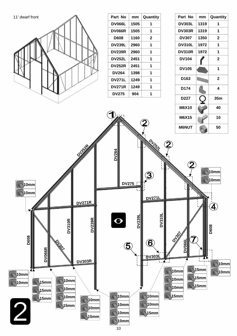
2 FRONT Again ensuring that the gable framework is rubbered-up follow the diagrams to assemble each end of the building. Make sure that you have inserted the extra bolts utilised in sections 4 and 5. On the roof and side corner bars not every rubber channel will require rubber unless it is to be utilised in a partition (see separate manual and section P).
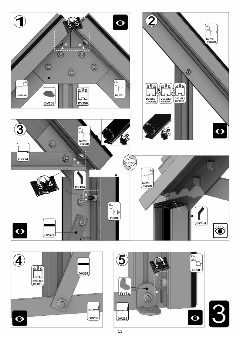
3 REAR
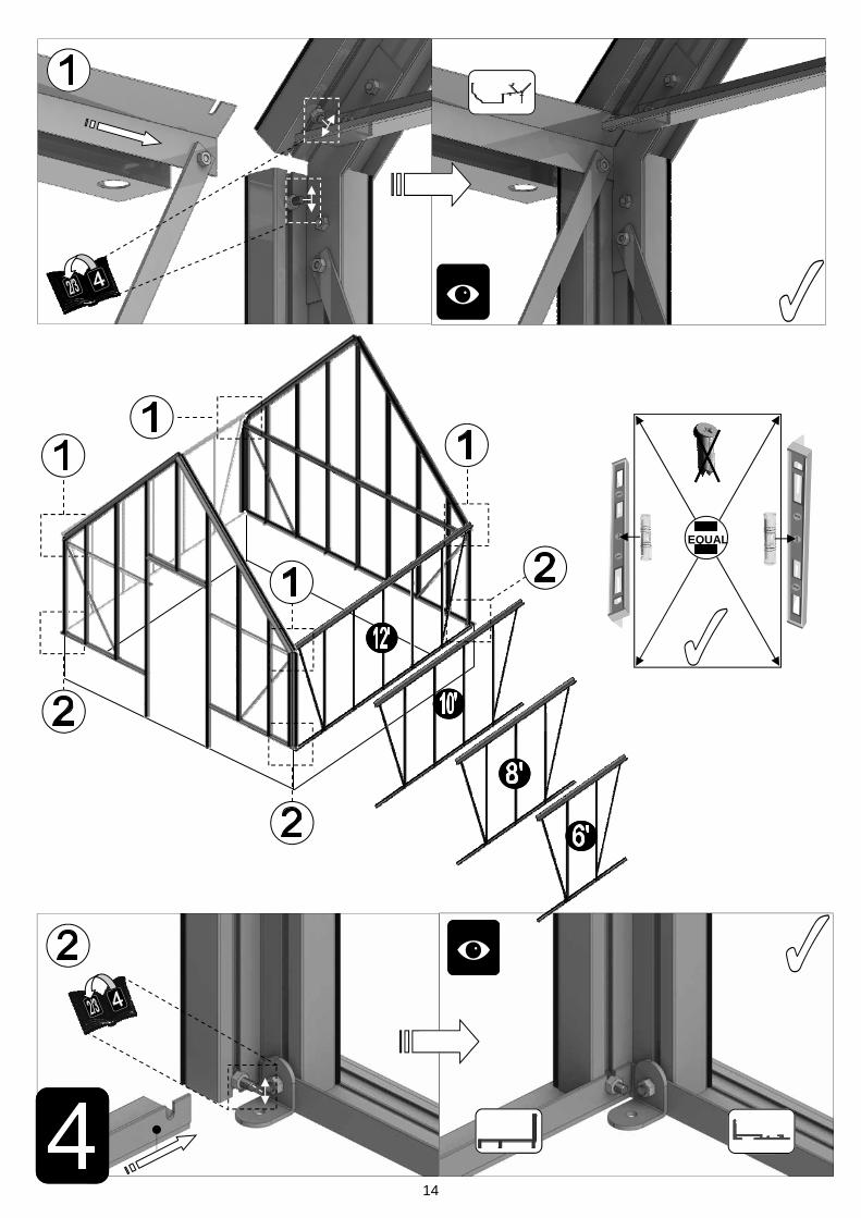
4 JOINING THE FOUR SIDES
Take the two sides (1) and both gables (2 & 3) and join them together on your base. It is a good idea to tie some lad-ders to the sides to support them if you do not have anyone to hold them for you.
5 LOUVRE
They attach to the building during the glazing process (8) like a piece of glass with a black separator above them. If you are fitting an optional auto-louvre then you need to carefully drill (3mm bit) out the rivets which mount the handle to the frame. You can then either utilise those holes or create more to mount the unit.
6
ROOF
Attach the ridge and then the rubbered-up roof bars ensuring that they are fully butted up to the ridge and down onto the gutter. Attach your cresting before you glaze the building to give yourself more room to work. Utilise the 22mm bolts slid into the side (section 1) and roof bars to attach your DV100 and DV101 spandrels. On longer models you may need to carefully prop up the roof and tie the sides together to keep the ridge and gutters straight (i.e. not sagging or bowed) until the building is fully glazed.
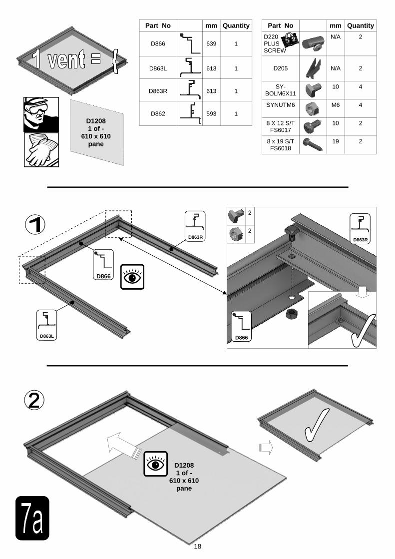
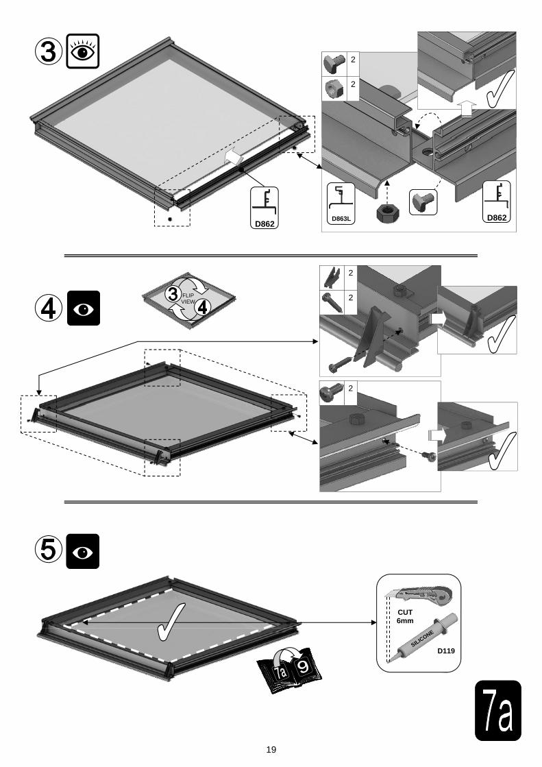
7a VENT Once the vent is glazed add silicone to the vent sides and top. Stand the vent/s on their hinge (vent top) and then leave the silicone to set.
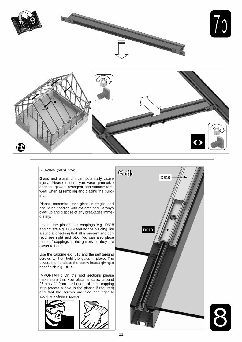
7b VENT SLAM The slam bar ‘D079’ can be moved up and down between the roof glazing bars so that it can be butted down onto the pane of glass beneath, the autovent will be attached to it later on (9).
8
GLAZING
Layout the bar cappings and covers around the building like a sundial checking that all is present and correct. You can also place the roof cappings in the gutters so they are closer to hand. The glass in the ends has to bevel on the black separator strip, this bevelling action allows the glass to tuck underneath the roof corner canopy. Use the capping and the self tapping screws to then hold the glass in place. The covers then enclose the screw heads giving a neat finish. It is a good idea to glaze two roof sections first to ensure the building is square followed by two side sections to ensure the building isn't leaning. IMPORTANT: On the roof sections please make sure that you place a screw around 25mm / 1” from the bottom of each capping strip (create a hole in the plastic if required) and that the screws are nice and tight to avoid any glass slippage.
9 VENT ATTACHMENT
Take the assembled vent and slide the vent hinge ‘D866’ into the end of the ridge allowing the vent the pivot open and closed. Vent stops go either side of the vent to stop any lateral movement (so insert stop / vent / stop). Attach the Bay-liss XL autovents.
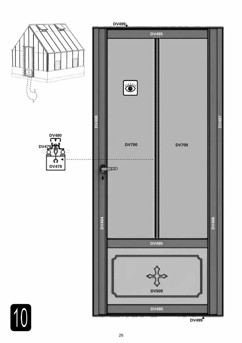
10 DOOR ATTACHMENT
Your door comes pre-constructed and locked minus the handles and their pivot pin but now it needs to be mounted to the front end of your building. Utilise the ‘DV522’ plates and twist in crop headed bolts to join the door and its frame to the building (pinch the door frame against your long front verticals whilst tightening your ‘DV522’ plates to ensure that there is no gap). If you are struggling to eradicate the gap between the door frame and verticals then some silicone can be carefully applied to the area to create a vertical seal. Be careful not to lock yourself in the building and to avoid dam-age do not open the door until it is attached to the front gable. Getting the door to swing perfectly without dropping or rubbing on the ground may require some small but vital adjustments. You may also need to insert a packer underneath the door frame hinge to increase ground clearance. Part ‘DV275’ canopies the door frame top hiding the clearance space at the top of the door. The door can only be made to swing inwards. IMPORTANT: Please do NOT let the door slam open or closed as it is likely to cause damage to the door and the frame. Please twist the handle to open and close. Please also be aware that your door KEYS (3 provided) are unique to the building so they should not be stored together.
11 ANCHORING DOWN
Now that the greenhouse is finished and the door and vent/s are operating without interference then you need to an-chor the building down using 2” rawl plugs and screws. Use a 7mm masonry bit in a hammer drill to create the holes.
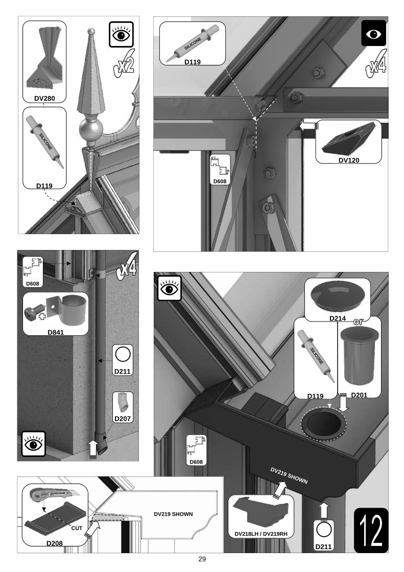
12 FINISHING TOUCHES
Now that the main body of the structure is complete you can add; downpipe fittings, eave bungs, gutter stop ends. It is also important to carefully apply some silicone to the internal eaves corners and external and internal ridge corners to minimise the chance of water entering the structure.
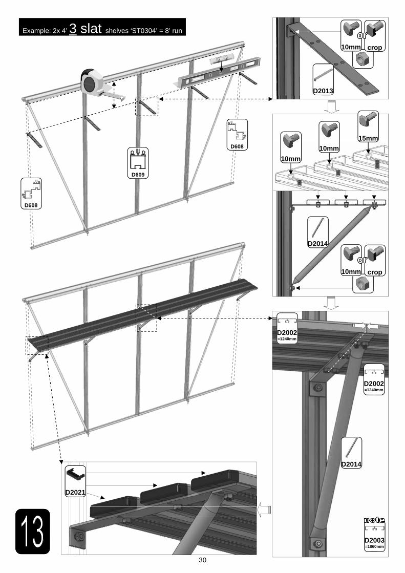
13 OPTIONAL SHELVING
Robinsons integral cantilever staging and shelving attaches to the inside of the greenhouse frame using either square head bolts (insert four into each side glazing bar ’D609’ during construction of the sides (1)) or rectangular ‘crop head’ bolts which can be fitted retrospectively (both sets of bolts accompany the shelving/staging). This system allows the height of either the staging or the shelf to be set at an operator specific height. Commonly the staging brackets are set 900mm from the cills though you can alter this to suit the end user/s. The aluminium shelf / staging slats come in two lengths; (4’):1240mm ‘D2002’ and (6’):1860mm ’D2003’. These slats can combine to create any length of staging re-quired, i.e. 4’+6’ = 10’ etc...
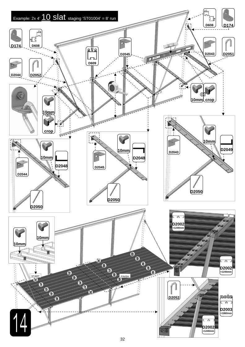
14 OPTIONAL STAGING

4
Section Ref
Part No.
Section Size (mm)
11 6
11 8
11 10
11 12
Section Ref
Part No.
Section Size (mm)
11 6
11 8
11 10
11 12
D043 1894 2
D021 2514 2
D022 3134 2
D023 3754 2
DV213 1897 2
DV210 2517 2
DV211 3137 2
DV212 3757 2
D604 1316 4
D609
1160
4
6
8
10
RUBBER
1000 (1m)
10
14
19
24
D174
N/A
4
4
8
8
DV204 1897 1
DV201 2517 1
DV202 3137 1
DV203 3757 1
DV255
2450
4
6
8
10
RUBBER
1000 (1m)
20
30
40
50
D866
639
2
2
4
4
D863L
613
2
2
4
4
D863R
613
2
2
4
4
D862
593
2
2
4
4
D079
PLUS FLUFF
590
2
2
4
4
D114
N/A
4
4
8
8
D220 PLUS FS6060
SCREW
N/A
4
4
8
8
D205
N/A
4
4
8
8
DV232 3548 1
DV303L 1319
1
DV303R 1
D608
1160
4
DV066L 1505
2
DV066R 2
DV239L 1
DV239R 1
DV310L 1972
2
DV310R 2
DV312L 2438
1
DV312R 1
DV259
2879
1
DV271L 1249
1
DV271R 1
DV274
3402
1
DV307 1350 4
DV252L 2451
2
DV252R 2
DV264
1398
1
2960
DV104
N/A
4
RUBBER
1000 (1m)
71
D174
N/A
11
DV105
N/A
2
DV275
904
1
D163
90
2

5
1 D618 1144 4 6 8 10
2/3 DV403L/R 1505 2 + 2
10 DV479 1384 1
2/3 DV610L/R 1972 2 + 2
3 DV612L/R 2438 1 + 1
2 DV639L/R 2960 1 + 1
3 DV659 2879 1
2 / 10 DV664 1373 1
5 DV655 1880 4 6 8 10
5 D870 601 4 6 8 10
2/3 D610 1160 4
1 D620 1144 4
5 D871 601 4
5 DV652 1871 4
2/3 D614 1162
1 D619 1144 8 10 12 14
10 DV480 1384 1
2/3 DV611L/R 1972 2 + 2
3 DV613L/R 2438 1 + 1
2/3 DV615L/R 1505 2 + 2
2 DV640L/R 2960 1 + 1
5 DV658 2481 8
3 DV665 2879 1
2 / 10 DV670 1373 1
4
10 12 14
Section Ref
Part No.
Section Size (mm)
11 6
11 8
11 10
11 12
D522
N/A
10
D119
N/A
1
DV120
N/A
4
D841
N/A
2
D211
PIPE
1625
2
D207
N/A
2
D214 N/A 2
D201
N/A
2
D208 N/A 2
SILICONE
10mm
SYBOLM6X11
10mm
84
90
96
SYBOLM6X15
15mm
31
33
35
SYBOLM6X22
22mm
24
36
48
102
37
60
SYNUTM6 M6
NUT
139
159
179
199
MA
IN F
RA
ME
QU
AN
TIT
IES
VE
NT
S /
DO
OR
S e
tc S
EP
ER
AT
E
Section Ref
Part No.
Section Size (mm)
11 6
11 8
11 10
11 12
DV219 N/A 2
DV218 N/A 2

6
7
PARTITION ONLY
REFER TO SEPARATE
MANUAL
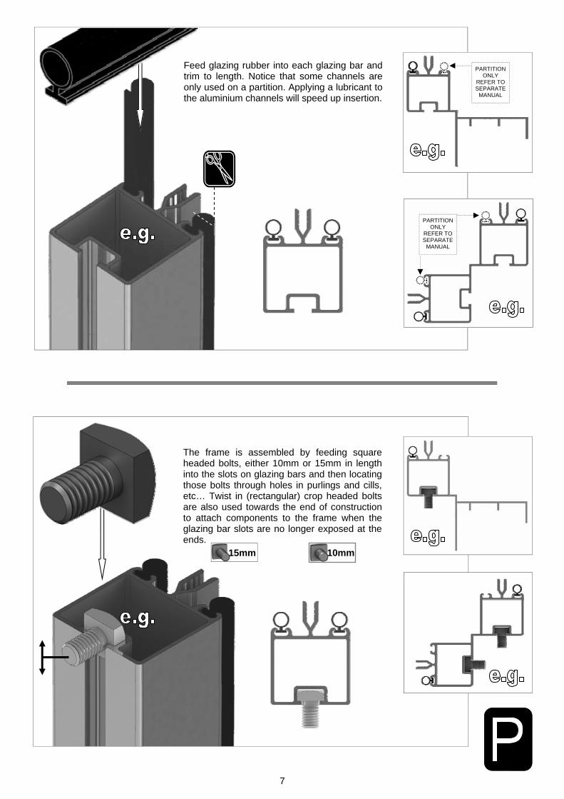
Feed glazing rubber into each glazing bar and trim to length. Notice that some channels are only used on a partition. Applying a lubricant to the aluminium channels will speed up insertion.
The frame is assembled by feeding square headed bolts, either 10mm or 15mm in length into the slots on glazing bars and then locating those bolts through holes in purlings and cills, etc… Twist in (rectangular) crop headed bolts are also used towards the end of construction to attach components to the frame when the glazing bar slots are no longer exposed at the ends.
10mm 15mm
PARTITION ONLY
REFER TO SEPARATE
MANUAL

8
6 X 2
12 X 2
8 X 2
10 X 2
DV213
D043
DV210
D021
DV211
D022
DV212
D023
Part No mm Quantity
DV213 1897 2
D043 1894 2
D609 1160 4
D604 1316 4
D174 4
SYBOLM6X11
4
SYBOLM6X15
8
SYNUTM6 12
6 X 2 DWARF
Rubber 1000 10
SYBOLM6X22
8
Part No mm Quantity
DV210 2517 2
D021 2514 2
D609 1160 6
D604 1316 4
D174 4
SYBOLM6X11
6
SYBOLM6X15
10
SYNUTM6 16
8 X 2 DWARF
Rubber 1000 14
SYBOLM6X22
12
Part No mm Quantity
DV211 3137 2
D022 3134 2
D609 1160 8
D604 1316 4
D174 8
SYBOLM6X11
8
SYBOLM6X15
12
SYNUTM6 20
10 X 2 DWARF
Rubber 1000 19
SYBOLM6X22
16
Part No mm Quantity
DV212 3757 2
D023 3754 2
D609 1160 10
D604 1316 4
D174 8
SYBOLM6X11
10
SYBOLM6X15
14
SYNUTM6 24
12 X 2 DWARF
Rubber 1000 24
SYBOLM6X22
20

9
D604
D604
15mm
D609
10mm
D609
TRANSIT BOLT ON
DIAGONALS 15mm 22mm
10
11’ dwarf front
D60
8
10mm
10mm
10mm
10mm
15mm
15mm
D60
8
DV307
DV3
07 DV
310R
DV
264
DV252R
10mm
15mm
10mm
15mm 15mm
15mm
15mm
10mm
10mm 10mm
10mm
DV
066R
DV
066L
10mm
15mm
10mm
10mm
10mm
15mm
10mm
10mm
DV252L
DV275
DV
310L
10mm
15mm
10mm
10mm
10mm
10mm
10mm
DV
239R
DV
239L
DV271R DV271L
DV303R
Part No mm Quantity
DV066L 1505 1
DV066R 1505 1
D608 1160 2
DV239L 2960 1
DV239R 2960 1
DV252L 2451 1
DV252R 2451 1
DV264 1398 1
DV271L 1249 1
DV271R 1249 1
DV275 904 1
Part No mm Quantity
D174 4
M6X10 40
M6X15 10
M6NUT 50
DV104 2
D227 35m
DV105 1
DV303L 1319 1
DV303R 1319 1
DV307 1350 2
DV310L 1972 1
DV310R 1972 1
D163 2
DV303L

11
DV252L
DV303L / DV303R
D174
DV252R
D608
DV105 DV264
DV239L / DV239R
DV252L / DV252R
DV239L / DV239R
DV275
D163
DV303L / DV303R
DV307
D608
DV307
DV252L / DV252R
DV104
DV104
FLIP VIEW
DV271L / DV271R
DV252L / DV252R

12
Part No mm Quantity
DV066L 1505 1
DV066R 1505 1
D608 1160 2
DV232 3548 1
DV252L 2451 1
DV252R 2451 1
DV274 3402 1
DV307 1350 2
DV310L 1972 1
DV310R 1972 1
DV312L 2438 1
DV312R 2438 1
DV259 2879 1
Part No mm Quantity
D174 7
M6X10 32
M6X15 13
M6NUT 45
DV104 2
D227 36m
DV105 1
DV232
D60
8
10mm
10mm
10mm
10mm
15mm
15mm
D60
8
DV307
DV3
07 DV
310R
DV
259
DV274
DV252R
10mm
15mm
10mm 15mm 15mm
15mm
15mm
10mm
10mm 10mm
10mm
DV
066R
DV
066L
10mm
15mm
10mm
10mm
10mm
15mm
10mm
10mm
DV252L
DV
312L
DV
312R
DV
310L
11’ dwarf rear
13
DV252L
DV232
D174
DV307
DV232
DV252R
D608
DV105 DV259
DV310L / DV310R
DV252L / DV252R
DV310L / DV310R
DV066L / DV066R
DV312L / DV312R
D608
DV307
DV252L / DV252R
DV274
DV104
DV104
DV252L / DV252R
FLIP VIEW
14
EQUAL

15
D168L
D168R (handle)
552
552
1
1
D165
612
2
D166
552
2
FS6013
12
4
Part No mm Quantity
INTERNAL VIEW
D165
D165
D166 D166
D168L D168R
D165
PINCH ALL GLASS RETAINERS BEFORE GLAZING
D729TG - 100 x 525 panes x 6

16
Part No mm Quantity
DV204 1897 1
DV255 2450 4
DV100 n/a 4
DV101 n/a 2
RUBBER 1000 15 SYBOLM6X11 8 SYBOLM6X22 16
SYNUTM6 32
6’ Part No mm Quantity
DV201 2517 1
DV255 2450 6
DV100 n/a 6
DV101 n/a 3
RUBBER 1000 22 SYBOLM6X11 12 SYBOLM6X22 24
SYNUTM6 48
8’ Part No mm Quantity
DV202 3137 1
DV255 2450 8
DV100 n/a 8
DV101 n/a 4
RUBBER 1000 30 SYBOLM6X11 16 SYBOLM6X22 32
SYNUTM6 64
10’ Part No mm Quantity
DV203 3757 1
DV255 2450 10
DV100 n/a 10
DV101 n/a 5
RUBBER 1000 36 SYBOLM6X11 20 SYBOLM6X22 40
SYNUTM6 80
12’
DV282
ROFINALU
DV281
RO CRE ALU
CUT 6mm
SILICONE
D119
EQUALx2
End finials need to be pinched onto the ridge using ‘DV282’ grub screws. Depending on your ridge length a half cresting may need to be cut. Some
spacer bar may also be required ‘DV281’ cut into two equal sections. Each finial and cresting piece needs to be siliconed ‘D119’ into place.

17
2
1
3
4
1
DV255
D609
2
DV255
DV255
4
3
10mm
22mm
10mm
22mm
DV101
DV100
DV100
18
D1208 1 of -
610 x 610 pane
D866
D863R
D863L
D866
639
1
D863L
613
1
D863R
613
1
D862
593
1
Part No mm Quantity
D220 PLUS SCREW
N/A 2
D205
N/A
2
SY-BOLM6X11
10 4
SYNUTM6 M6 4
8 X 12 S/T FS6017
10 2
Part No mm Quantity
8 x 19 S/T FS6018
19 2
D863R
D866
2
2
D1208 1 of -
610 x 610 pane
19
D862 D862 D863L
2
2
2
2
2
FLIP VIEW
D119
CUT 6mm
SILICONE

20
D114
D079
FLIP VIEW
D079 PLUS FLUFF
590
1
D114 N/A 2
Part No mm Quantity
SY-BOLM6X11
10 2
SY-BOLM6X15
15 2
SYBOLM6 X11CROP
10 2
SYNUTM6 N/A 4
Part No mm Quantity
D114
21
GLAZING (plans pto): Glass and aluminium can potentially cause injury. Please ensure you wear protective goggles, gloves, headgear and suitable foot-wear when assembling and glazing the build-ing. Please remember that glass is fragile and should be handled with extreme care. Always clear up and dispose of any breakages imme-diately. Layout the plastic bar cappings e.g. D618 and covers e.g. D619 around the building like a sundial checking that all is present and cor-rect, see right and pto. You can also place the roof cappings in the gutters so they are closer to hand. Use the capping e.g. 618 and the self tapping screws to then hold the glass in place. The covers then enclose the screw heads giving a neat finish e.g. D619. IMPORTANT: On the roof sections please make sure that you place a screw around 25mm / 1” from the bottom of each capping strip (create a hole in the plastic if required) and that the screws are nice and tight to avoid any glass slippage.
D618
D619

22
D614
D610
DV615L
DV403L
DV615R
DV403R
D619
D620
D619
D620
D619
D618
D619
D618
D614
D610
DV611R
DV610R
D614
D610
D614
D610
D619
D618
DV611L
DV610L
DV665
DV659
DV670
DV664
DV615L
DV403L
DV615R
DV403R
D619
D618
DV611L
DV610L
DV611R
DV610R
DV479
DV480
ON DOOR
PART No
Section Size (mm)
D618 1144
DV403L/R 1505
DV479 1384
DV610L/R 1972
DV612L/R 2438
DV639L/R 2960
DV659 2879
DV664 1373
D610 1160
D620 1144
D871 601
DV652 1871
D614 1162
D619 1144
DV480 1384
DV611L/R 1972
DV613L/R 2438
DV615L/R 1505
DV640L/R 2960
DV658 2481
DV665 2879
DV670 1373
DV655 1880
D870 601
DV640L
DV639L
DV640R
DV639R
D871 D871 D870 D870 D870 D870 D870
DV652
DV658
DV652
DV658
DV655
DV658
DV655
DV658
DV655
DV658
DV655
DV658 DV658
DV655
D619
D618
DV613L
DV612L
DV613R
DV612R

23
PART No Size (mm) 8’ 10’ 12’
D1216 S 610 X 1162 6 8 10
610x1890 R 610 X 1890 8 10 12
D1208 A 610 X 610 8 10 12
D625 N 305 X 1162 4
D769 G 457 X 1162 10
DV700 D 357 X 1384 2
DV507 P ANGLE 4
DV713 K ANGLE 4
DV714 J ANGLE 4
DV716 T ANGLE 2
DV717 H ANGLE 2
D223/B Cut to 904mm 1
D101 /
ROSEPS
610 long (inc cuts to
457&305mm)
12 + (1 per louver)
6’
4
6
6
R
S S S
R
A
R R R
A
S
M 610 X 550 1
L 525 X 100 6
610 long 1
D624
D729
D101 / ROSEPS
M
L
457
794
337 K J
457
1262
805
P 20
305
325
940
H 457
1397
457
1729
1272
T
A A A A
R
G D
N
P
D N
H H
P
K K
G G
J J
G
G
P P
G N G
K K
N G
T T
G G
J J
ROOF PANES OVERLAP

24
D220
D220

25
D079
D862
26
DV495
DV499
DV
498
DV
494
DV
497
DV
496
DV495
DV495
DV499
DV500
DV700 DV700
DV478
DV480
DV479

27
Part No Quantity
D522 10
SYBOLM6 X11CROP
20
SYNUTM6 20
DV522
DV275

28
O7mm
29
D211
D201 D119
SILICO
NE
D214
D608
D208
CUT DV218LH / DV219RH
DV219 SHOWN
DV219 SHOWN
D207
D211
D841
D608
D119
SILICONE
DV120
D608 D119
SILICO
NE
DV280
30
D2021
15mm
10mm
crop
10mm
10mm
D2013
D2014
D2014
crop 10mm
D2002 =1240mm
D2003 =1860mm
D2002 =1240mm
Example: 2x 4’ 3 slat shelves ‘ST0304’ = 8’ run
D609
D608
D608

31
Example: 2x 4’ 7 slat staging ‘ST0704’ = 8’ run
10mm
10mm
D2044
D2043
D2045
D2045 D2044 D2043
D2046 D2046 D2047
D2042 D2042 D2042
crop
10mm
10mm 10mm 10mm
crop
10mm
START
FINISH
D2002 =1240mm
D2002 =1240mm
D2002 =1240mm
D2003 =1860mm
D609
D608
D608
32
Example: 2x 4’ 10 slat staging ‘ST01004’ = 8’ run
D2045
D2045
D2043 D2049
D2050
D2050
10mm
crop
10mm
START
D2002 =1240mm
D2002 =1240mm
D2003 =1860mm
10mm
10mm
FINISH
D2048
D2044
D2048
D2050
10mm
10mm
D2044
D174
D2052
D174
D2051 D2043
crop 10mm
D2002 =1240mm
D2052
D608
D609
D608
33
34

35

36
www.robinsonsgreenhouses.co.uk
To contact Robinsons Customer Services email us at [email protected] or call us on 01782 385 409.
Our address is Robinsons Greenhouses, Unit 19 Blythe Park, Cresswell, Stoke-on-Trent, Staffordshire, ST11 9RD
Please be aware that this is a new multi-national manual. If you spot any errors or have any constructive comments regarding the manual please email [email protected] and I will make the necessary amendments.
In addition any photographs of completed buildings would be most appreciated to add to our portfolio.
THIS GREENHOUSE BOX WAS PACKED BY: DATE:___________________ ________________________________________________________________________________