Embed Size (px)
DESCRIPTION
service manual
Citation preview
RM-84/99Nokia Customer Care BB Troubleshooting and Manual Tuning Guide
(This page left intentionally blank.)
Page 1–2 Company Confidential Issue 1Copyright ©2005 Nokia. All Rights Reserved.
Table of ContentsBaseband troubleshooting...........................................................................................................................................................1–5Dead or jammed device troubleshooting...............................................................................................................................1–6General power checking troubleshooting...............................................................................................................................1–7Clocking troubleshooting.............................................................................................................................................................1–8OMAP1710 troubleshooting.........................................................................................................................................................1–9Charging troubleshooting..........................................................................................................................................................1–11Battery current measuring fault troubleshooting.............................................................................................................1–12Flash programming fault troubleshooting...........................................................................................................................1–13CMT SDRAM memory troubleshooting....................................................................................................................................1–16CMT NOR flash fault troubleshooting......................................................................................................................................1–17OMAP1710 memory troubleshooting.....................................................................................................................................1–18Power key troubleshooting.......................................................................................................................................................1–20USB interface troubleshooting.................................................................................................................................................1–21SIM card troubleshooting...........................................................................................................................................................1–23MMC troubleshooting...................................................................................................................................................................1–25Keyboard troubleshooting.........................................................................................................................................................1–26Slider switch troubleshooting..................................................................................................................................................1–28FM radio troubleshooting..........................................................................................................................................................1–29Certificate restoring for BB5.0 products................................................................................................................................1–29Display module troubleshooting.............................................................................................................................................1–35
General instructions for display troubleshooting........................................................................................................1–35Display fault troubleshooting.............................................................................................................................................1–37Display and keyboard backlight troubleshooting........................................................................................................1–38ALS troubleshooting...............................................................................................................................................................1–39LED driver troubleshooting..................................................................................................................................................1–41
Bluetooth troubleshooting........................................................................................................................................................1–42Introduction to Bluetooth troubleshooting...................................................................................................................1–42Bluetooth settings for Phoenix..........................................................................................................................................1–44Bluetooth self tests in Phoenix...........................................................................................................................................1–44Bluetooth troubleshooting..................................................................................................................................................1–46Bluetooth BER failure troubleshooting............................................................................................................................1–47BT audio failure troubleshooting......................................................................................................................................1–49
Audio troubleshooting................................................................................................................................................................1–49Audio troubleshooting test instructions.........................................................................................................................1–49Internal earpiece troubleshooting....................................................................................................................................1–54Internal microphone troubleshooting.............................................................................................................................1–55IHF troubleshooting...............................................................................................................................................................1–56External microphone troubleshooting.............................................................................................................................1–57External earpiece troubleshooting....................................................................................................................................1–58Vibra troubleshooting...........................................................................................................................................................1–59
Baseband manual tuning guide...............................................................................................................................................1–60Energy management calibration.......................................................................................................................................1–60
List of TablesTable 1 Display module troubleshooting cases..................................................................................................................1–35Table 2 Pixel defects....................................................................................................................................................................1–36Table 3 Calibration value limits................................................................................................................................................1–60
RM-84/99BB Troubleshooting and Manual Tuning Guide Nokia Customer Care
Issue 1 Company Confidential Page 1–3Copyright ©2005 Nokia. All Rights Reserved.
List of FiguresFigure 1 Main troubleshooting tree..........................................................................................................................................1–5Figure 2 SysCLK from C7528 & C7531........................................................................................................................................1–9Figure 3 SleepCLK from R7558..................................................................................................................................................1–10Figure 4 Flash programming fault troubleshooting 1/2..................................................................................................1–13Figure 5 Flash programming fault troubleshooting 2/2..................................................................................................1–14Figure 6 Flashing pic 1. Take single trig measurement for the rise of the BSI signal.............................................1–15Figure 7 Flashing pic 2. Take single trig measurement for the rise of the BSI signal.............................................1–15Figure 8 CMT SDRAM CLK from pin J2806...............................................................................................................................1–16Figure 9 NOR CLK from J2813....................................................................................................................................................1–17Figure 10 COMBO NAND in boot pic 1. ...................................................................................................................................1–19Figure 11 USB 1: D-TXD (POP-PORT pin6) and D+RXD (POP-PORT pin7) voltage levels when USB connected..1–21Figure 12 USB 2: Take single triggered measurement on the rising edge of the Helen usb0_txen (J4813) line.1–22Figure 13 SIM interface signals.................................................................................................................................................1–23Figure 14 MMC card initialization............................................................................................................................................1–25Figure 15 Data transfer...............................................................................................................................................................1–26Figure 16 Ambient Light Sensor Calibration window.......................................................................................................1–39Figure 17 Phoenix settings for Bluetooth troubleshooting............................................................................................1–44Figure 18 Bluetooth self tests in Phoenix.............................................................................................................................1–45Figure 19 Single-ended output waveform of the Ext_in_HP_out measurement when earpiece is connected.1–52Figure 20 Differential output waveform of the Ext_in_IHF_out out loop measurement when speaker isconnected........................................................................................................................................................................................1–53Figure 21 Single-ended output waveform of the HP_in_Ext_out loop when microphone is connected...........1–53
RM-84/99Nokia Customer Care BB Troubleshooting and Manual Tuning Guide
Page 1–4 Company Confidential Issue 1Copyright ©2005 Nokia. All Rights Reserved.
Baseband troubleshooting
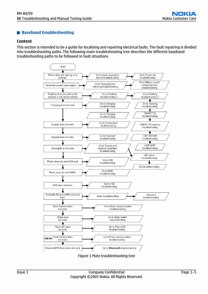
ContextThis section is intended to be a guide for localising and repairing electrical faults. The fault repairing is dividedinto troubleshooting paths. The following main troubleshooting tree describes the different basebandtroubleshooting paths to be followed in fault situations.
Figure 1 Main troubleshooting tree
RM-84/99BB Troubleshooting and Manual Tuning Guide Nokia Customer Care
Issue 1 Company Confidential Page 1–5Copyright ©2005 Nokia. All Rights Reserved.
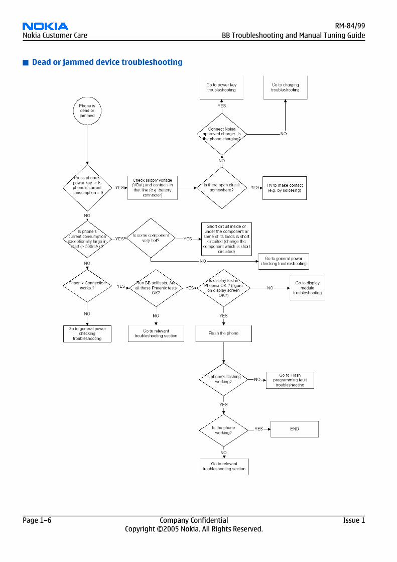
Dead or jammed device troubleshooting
RM-84/99Nokia Customer Care BB Troubleshooting and Manual Tuning Guide
Page 1–6 Company Confidential Issue 1Copyright ©2005 Nokia. All Rights Reserved.
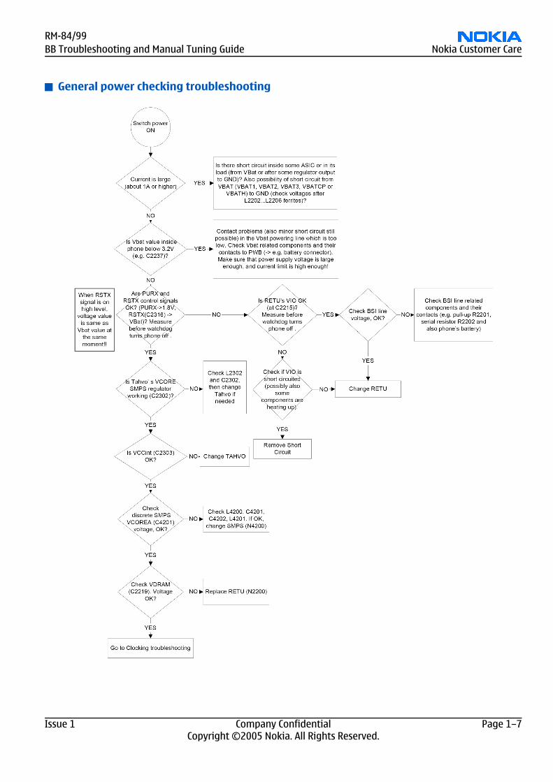
General power checking troubleshooting
RM-84/99BB Troubleshooting and Manual Tuning Guide Nokia Customer Care
Issue 1 Company Confidential Page 1–7Copyright ©2005 Nokia. All Rights Reserved.
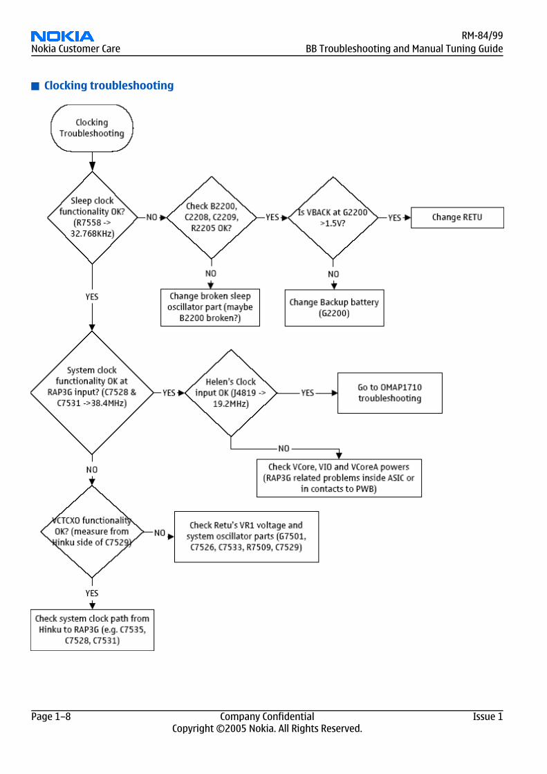
Clocking troubleshooting
RM-84/99Nokia Customer Care BB Troubleshooting and Manual Tuning Guide
Page 1–8 Company Confidential Issue 1Copyright ©2005 Nokia. All Rights Reserved.
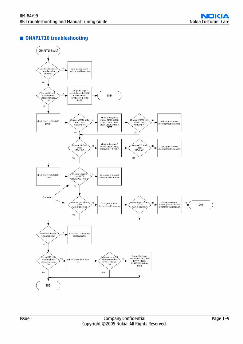
OMAP1710 troubleshooting
RM-84/99BB Troubleshooting and Manual Tuning Guide Nokia Customer Care
Issue 1 Company Confidential Page 1–9Copyright ©2005 Nokia. All Rights Reserved.
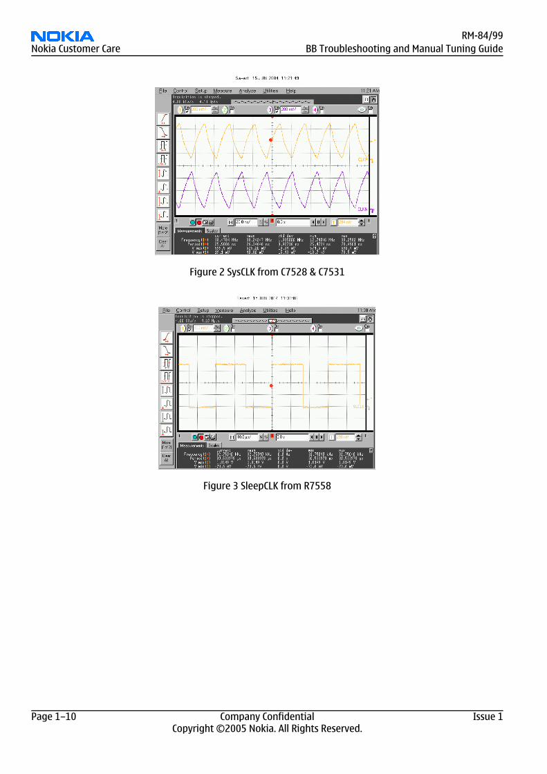
Figure 2 SysCLK from C7528 & C7531
Figure 3 SleepCLK from R7558
RM-84/99Nokia Customer Care BB Troubleshooting and Manual Tuning Guide
Page 1–10 Company Confidential Issue 1Copyright ©2005 Nokia. All Rights Reserved.
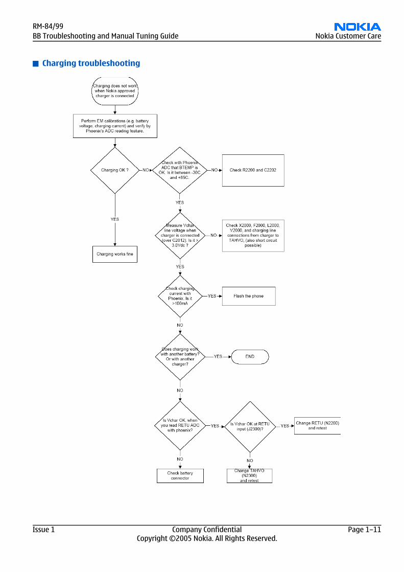
Charging troubleshooting
RM-84/99BB Troubleshooting and Manual Tuning Guide Nokia Customer Care
Issue 1 Company Confidential Page 1–11Copyright ©2005 Nokia. All Rights Reserved.
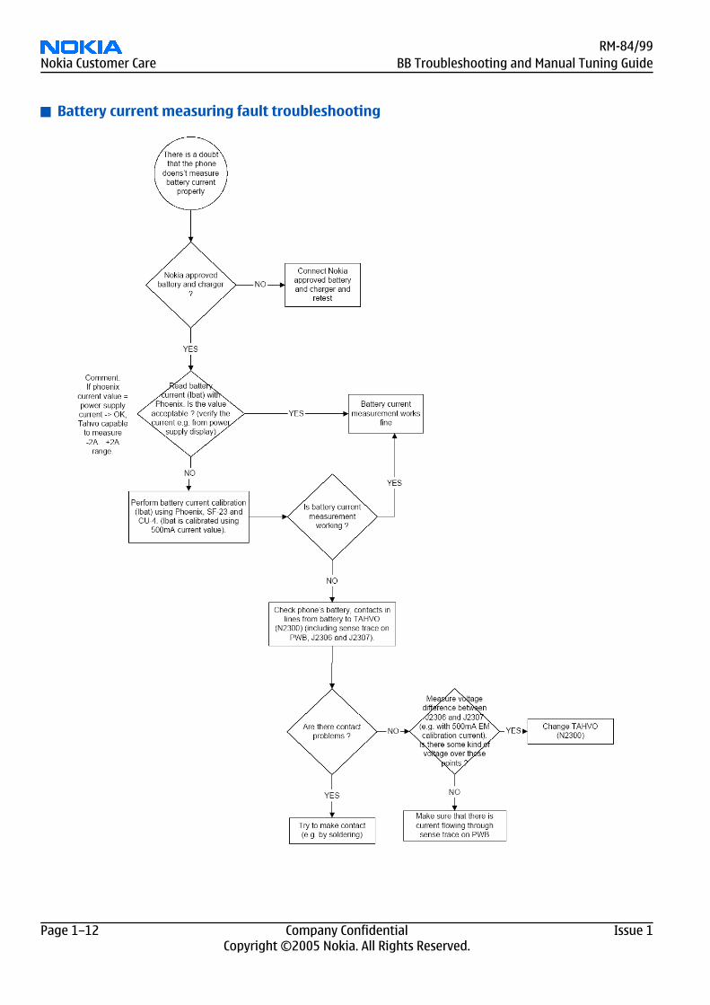
Battery current measuring fault troubleshooting
RM-84/99Nokia Customer Care BB Troubleshooting and Manual Tuning Guide
Page 1–12 Company Confidential Issue 1Copyright ©2005 Nokia. All Rights Reserved.
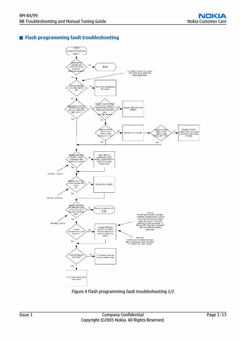
Flash programming fault troubleshooting
Figure 4 Flash programming fault troubleshooting 1/2
RM-84/99BB Troubleshooting and Manual Tuning Guide Nokia Customer Care
Issue 1 Company Confidential Page 1–13Copyright ©2005 Nokia. All Rights Reserved.
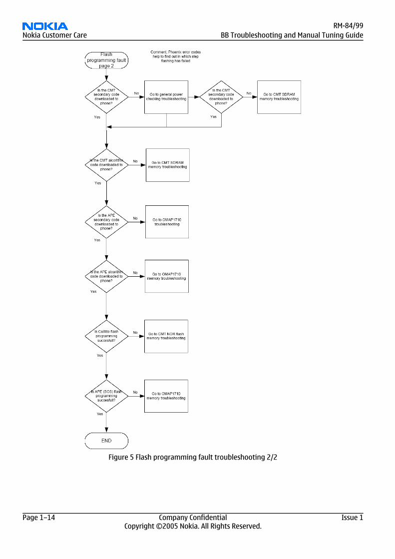
Figure 5 Flash programming fault troubleshooting 2/2
RM-84/99Nokia Customer Care BB Troubleshooting and Manual Tuning Guide
Page 1–14 Company Confidential Issue 1Copyright ©2005 Nokia. All Rights Reserved.

Figure 6 Flashing pic 1. Take single trig measurement for the rise of the BSI signal.
Figure 7 Flashing pic 2. Take single trig measurement for the rise of the BSI signal.
RM-84/99BB Troubleshooting and Manual Tuning Guide Nokia Customer Care
Issue 1 Company Confidential Page 1–15Copyright ©2005 Nokia. All Rights Reserved.
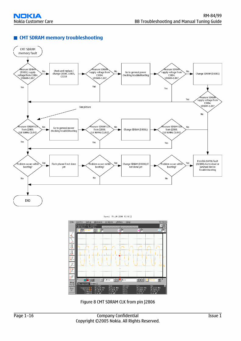
CMT SDRAM memory troubleshooting
Figure 8 CMT SDRAM CLK from pin J2806
RM-84/99Nokia Customer Care BB Troubleshooting and Manual Tuning Guide
Page 1–16 Company Confidential Issue 1Copyright ©2005 Nokia. All Rights Reserved.
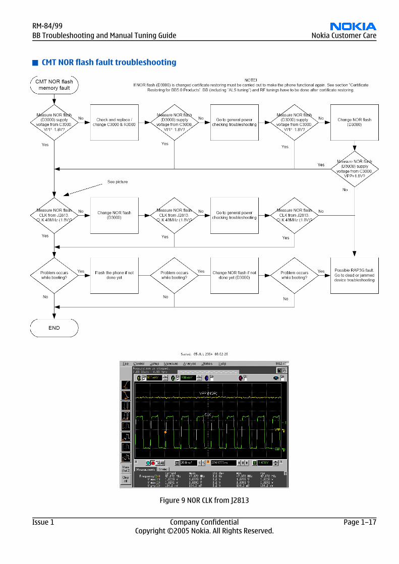
CMT NOR flash fault troubleshooting
Figure 9 NOR CLK from J2813
RM-84/99BB Troubleshooting and Manual Tuning Guide Nokia Customer Care
Issue 1 Company Confidential Page 1–17Copyright ©2005 Nokia. All Rights Reserved.
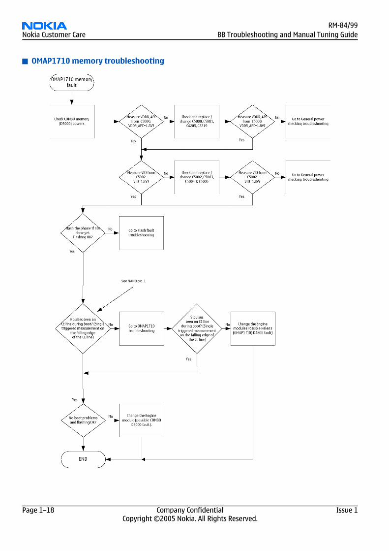
OMAP1710 memory troubleshooting
RM-84/99Nokia Customer Care BB Troubleshooting and Manual Tuning Guide
Page 1–18 Company Confidential Issue 1Copyright ©2005 Nokia. All Rights Reserved.
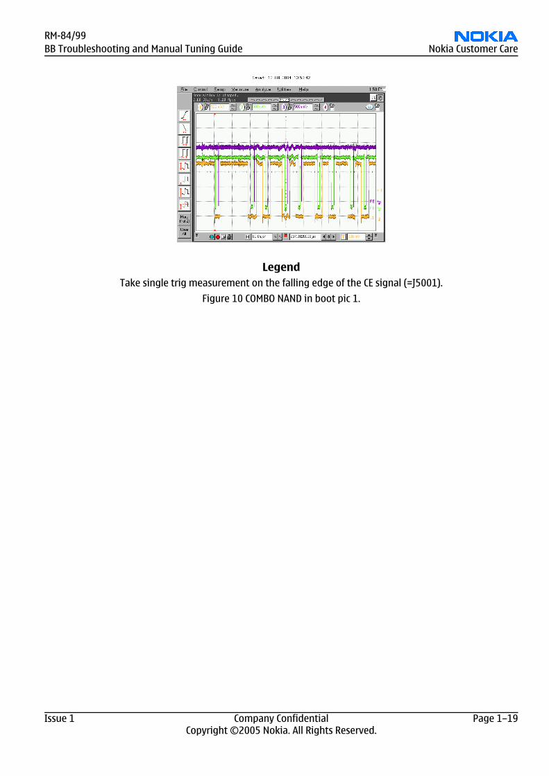
LegendTake single trig measurement on the falling edge of the CE signal (=J5001).
Figure 10 COMBO NAND in boot pic 1.
RM-84/99BB Troubleshooting and Manual Tuning Guide Nokia Customer Care
Issue 1 Company Confidential Page 1–19Copyright ©2005 Nokia. All Rights Reserved.
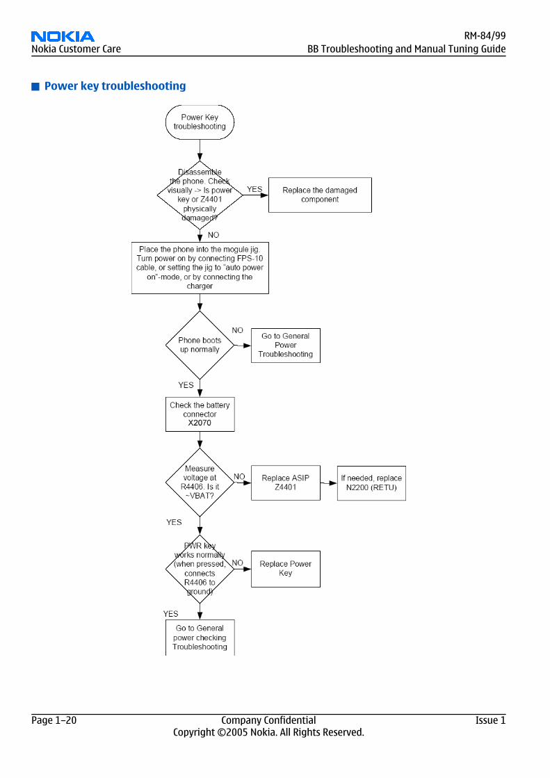
Power key troubleshooting
RM-84/99Nokia Customer Care BB Troubleshooting and Manual Tuning Guide
Page 1–20 Company Confidential Issue 1Copyright ©2005 Nokia. All Rights Reserved.
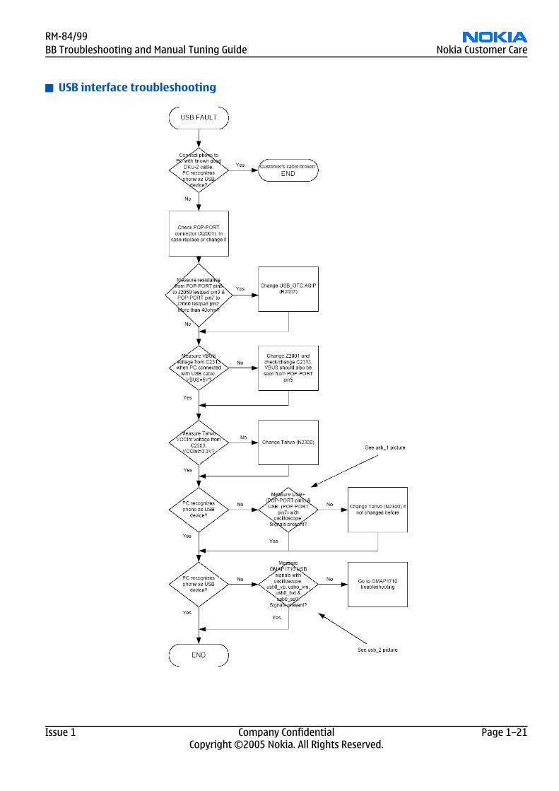
USB interface troubleshooting
RM-84/99BB Troubleshooting and Manual Tuning Guide Nokia Customer Care
Issue 1 Company Confidential Page 1–21Copyright ©2005 Nokia. All Rights Reserved.
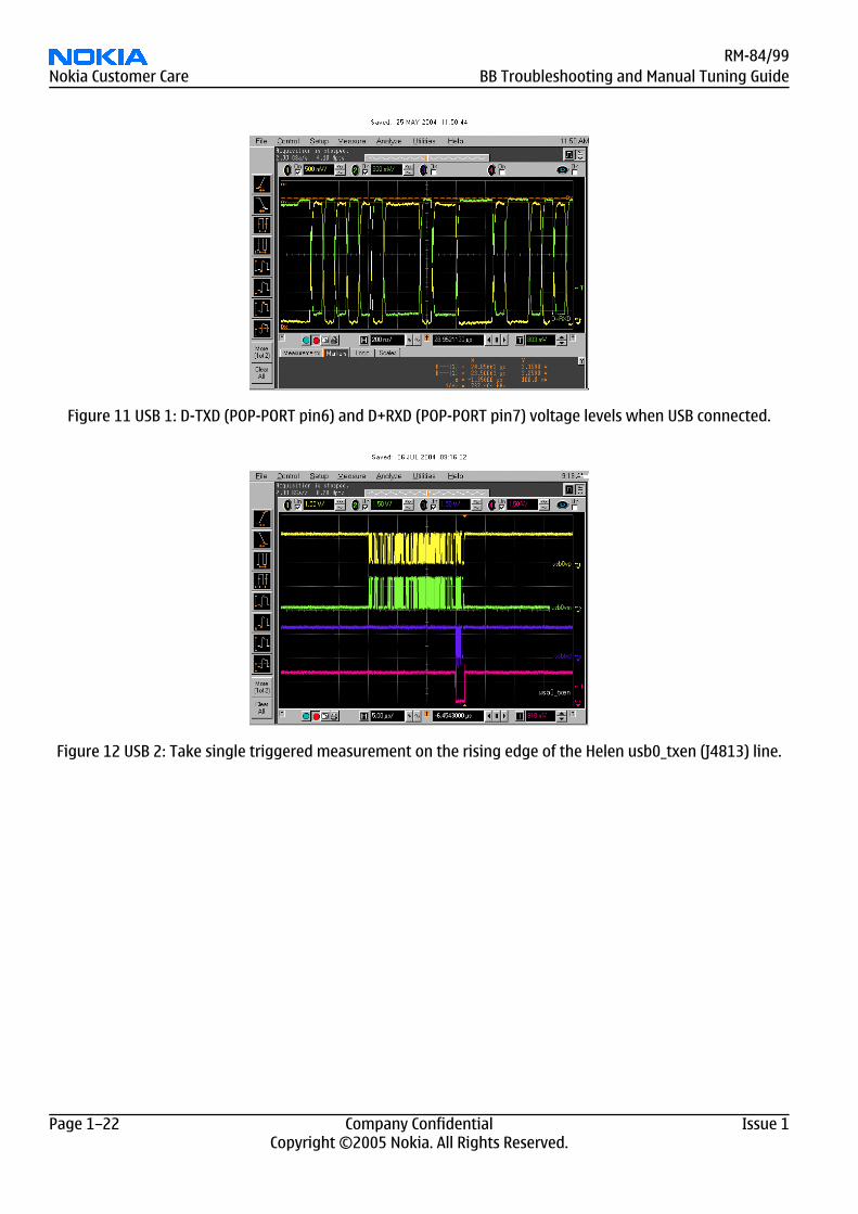
Figure 11 USB 1: D-TXD (POP-PORT pin6) and D+RXD (POP-PORT pin7) voltage levels when USB connected.
Figure 12 USB 2: Take single triggered measurement on the rising edge of the Helen usb0_txen (J4813) line.
RM-84/99Nokia Customer Care BB Troubleshooting and Manual Tuning Guide
Page 1–22 Company Confidential Issue 1Copyright ©2005 Nokia. All Rights Reserved.
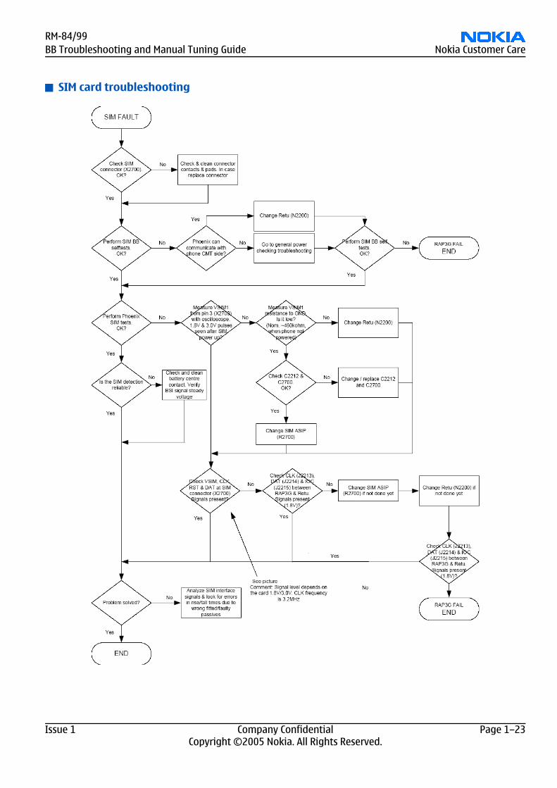
SIM card troubleshooting
RM-84/99BB Troubleshooting and Manual Tuning Guide Nokia Customer Care
Issue 1 Company Confidential Page 1–23Copyright ©2005 Nokia. All Rights Reserved.
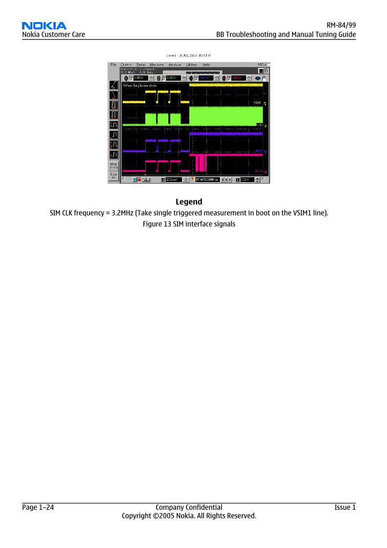
LegendSIM CLK frequency = 3.2MHz (Take single triggered measurement in boot on the VSIM1 line).
Figure 13 SIM interface signals
RM-84/99Nokia Customer Care BB Troubleshooting and Manual Tuning Guide
Page 1–24 Company Confidential Issue 1Copyright ©2005 Nokia. All Rights Reserved.
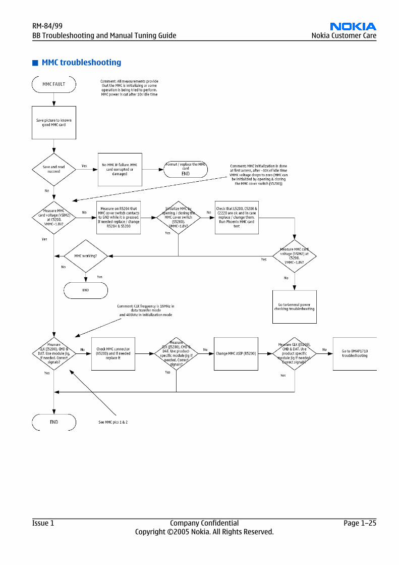
MMC troubleshooting
RM-84/99BB Troubleshooting and Manual Tuning Guide Nokia Customer Care
Issue 1 Company Confidential Page 1–25Copyright ©2005 Nokia. All Rights Reserved.
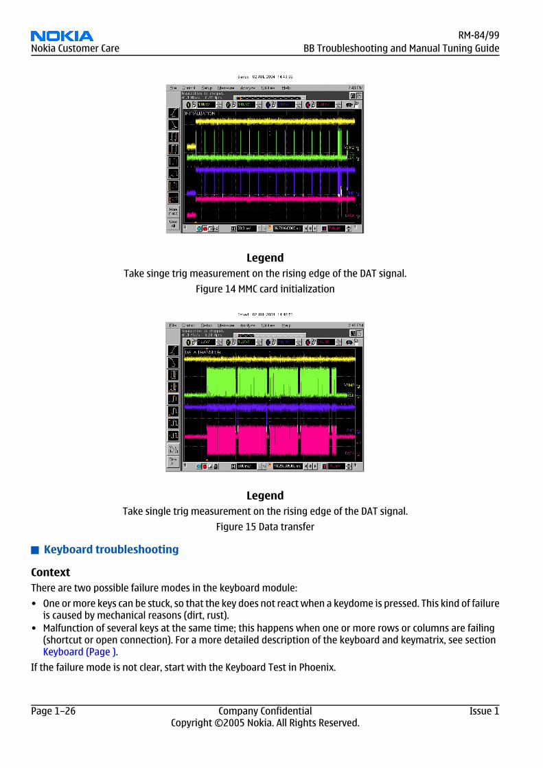
LegendTake singe trig measurement on the rising edge of the DAT signal.
Figure 14 MMC card initialization
LegendTake single trig measurement on the rising edge of the DAT signal.
Figure 15 Data transfer
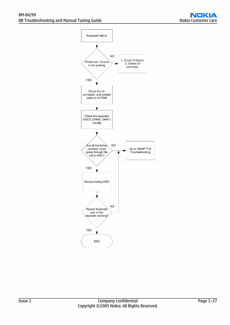
Keyboard troubleshooting
ContextThere are two possible failure modes in the keyboard module:
• One or more keys can be stuck, so that the key does not react when a keydome is pressed. This kind of failureis caused by mechanical reasons (dirt, rust).
• Malfunction of several keys at the same time; this happens when one or more rows or columns are failing(shortcut or open connection). For a more detailed description of the keyboard and keymatrix, see sectionKeyboard (Page ).
If the failure mode is not clear, start with the Keyboard Test in Phoenix.
RM-84/99Nokia Customer Care BB Troubleshooting and Manual Tuning Guide
Page 1–26 Company Confidential Issue 1Copyright ©2005 Nokia. All Rights Reserved.
RM-84/99BB Troubleshooting and Manual Tuning Guide Nokia Customer Care
Issue 1 Company Confidential Page 1–27Copyright ©2005 Nokia. All Rights Reserved.
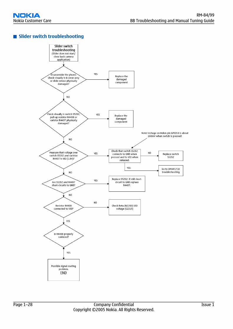
Slider switch troubleshooting
RM-84/99Nokia Customer Care BB Troubleshooting and Manual Tuning Guide
Page 1–28 Company Confidential Issue 1Copyright ©2005 Nokia. All Rights Reserved.
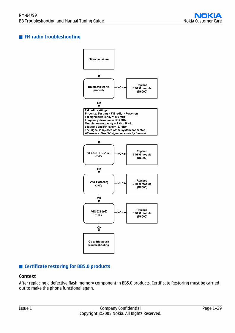
FM radio troubleshooting
Certificate restoring for BB5.0 products
ContextAfter replacing a defective flash memory component in BB5.0 products, Certificate Restoring must be carriedout to make the phone functional again.
RM-84/99BB Troubleshooting and Manual Tuning Guide Nokia Customer Care
Issue 1 Company Confidential Page 1–29Copyright ©2005 Nokia. All Rights Reserved.
Certificate restoring for BB5.0 products is basically the same process as IMEI / ESN Rebuild for DCT-4 generationproducts.
All tunings (RF & Baseband, UI) must be done after replacing the flash IC.
The procedure for Certificate Restoring when Flash IC has been replaced:
• Flash the phone with the latest available software (Use FPS-8 or FPS-10, USB Flashing does not work for adead BB5.0 phone).
• Create a request file.• Send the file to Nokia by e-mail.• When you receive a reply from Nokia, carry out Certificate Restoring.• Tune the phone completely (Note: SX-4 Smart Card is needed).• If phone resets after a certificate restore, reflash the phone again.
Required equipment and setup:
• Phoenix service software v 2004.39.7.70 or newer.• The latest phone model specific Phoenix data package.• PKD-1 dongle• SX-4 smart card (Enables BB5.0 testing and tuning features)• External smart card reader (Only when FPS-8 is used, FPS-10 has an integrated smart card reader)• Activated FPS-8 flash prommer OR FPS-10 flash prommer• Flash update package 03.18.004 or newer for FPS-8 or FPS-10 flash prommers• CU-4 control unit• USB cable from PC USB Port to CU-4 control unit• Phone model specific adapter for CU-4 control unit• PCS-1 cable to power CU-4 from external power supply• XCS-4 modular cable between flash prommer and CU-4
Note: CU-4 must be supplied with +12V from external power supply in all steps of Certificate Restoring.
Steps1. Program the phone software.
i Start Phoenix and login. Make sure the connection has been managed correctly for FPS-8 or FPS-10.ii Update the phone MCU software to the latest available version.
If the new flash is empty and the phone cannot communicate with Phoenix, the procedure in this caseis a “Dead Phone Flash” described below.
iii Choose the product manually from File → Open Product , and click OK.
Wait for the phone type designator (e.g. “RM-1” ) to be displayed in the status bar.iv Go to Flashing → SW Update and wait until Phoenix reads the product data as shown in the following
picture.
RM-84/99Nokia Customer Care BB Troubleshooting and Manual Tuning Guide
Page 1–30 Company Confidential Issue 1Copyright ©2005 Nokia. All Rights Reserved.
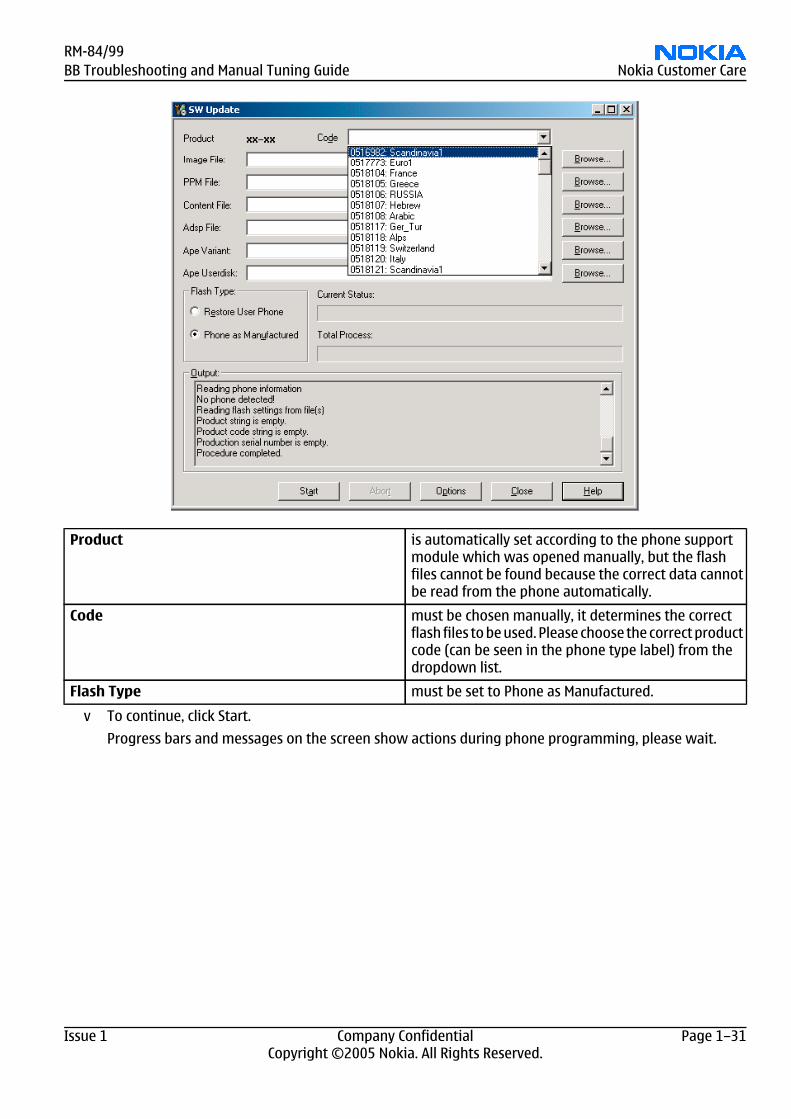
Product is automatically set according to the phone supportmodule which was opened manually, but the flashfiles cannot be found because the correct data cannotbe read from the phone automatically.
Code must be chosen manually, it determines the correctflash files to be used. Please choose the correct productcode (can be seen in the phone type label) from thedropdown list.
Flash Type must be set to Phone as Manufactured.
v To continue, click Start.
Progress bars and messages on the screen show actions during phone programming, please wait.
RM-84/99BB Troubleshooting and Manual Tuning Guide Nokia Customer Care
Issue 1 Company Confidential Page 1–31Copyright ©2005 Nokia. All Rights Reserved.
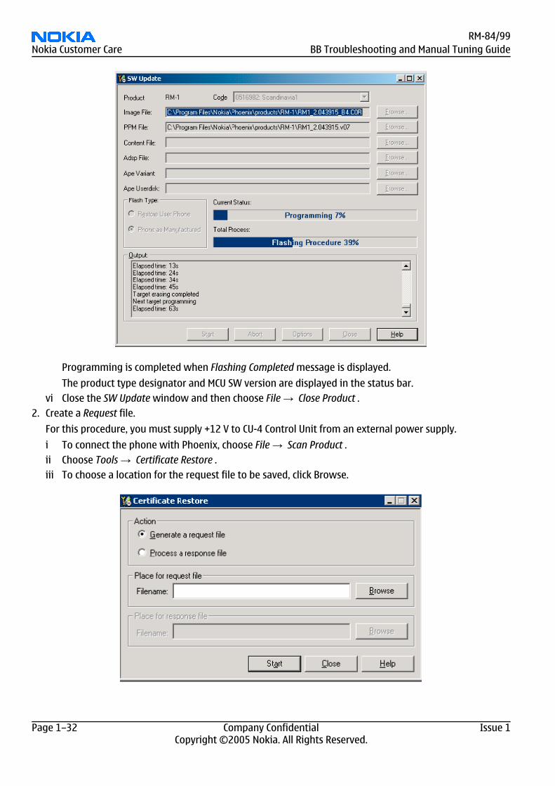
Programming is completed when Flashing Completed message is displayed.
The product type designator and MCU SW version are displayed in the status bar.vi Close the SW Update window and then choose File → Close Product .
2. Create a Request file.
For this procedure, you must supply +12 V to CU-4 Control Unit from an external power supply.
i To connect the phone with Phoenix, choose File → Scan Product .ii Choose Tools → Certificate Restore .iii To choose a location for the request file to be saved, click Browse.
RM-84/99Nokia Customer Care BB Troubleshooting and Manual Tuning Guide
Page 1–32 Company Confidential Issue 1Copyright ©2005 Nokia. All Rights Reserved.
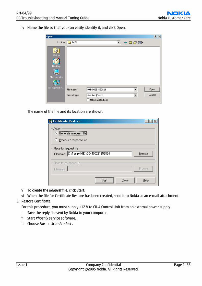
iv Name the file so that you can easily identify it, and click Open.
The name of the file and its location are shown.
v To create the Request file, click Start.vi When the file for Certificate Restore has been created, send it to Nokia as an e-mail attachment.
3. Restore Certificate.
For this procedure, you must supply +12 V to CU-4 Control Unit from an external power supply.
i Save the reply file sent by Nokia to your computer.ii Start Phoenix service software.iii Choose File → Scan Product .
RM-84/99BB Troubleshooting and Manual Tuning Guide Nokia Customer Care
Issue 1 Company Confidential Page 1–33Copyright ©2005 Nokia. All Rights Reserved.
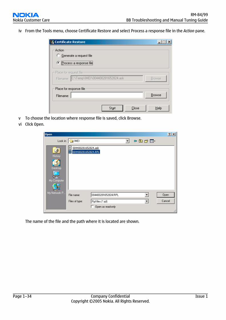
iv From the Tools menu, choose Certificate Restore and select Process a response file in the Action pane.
v To choose the location where response file is saved, click Browse.vi Click Open.
The name of the file and the path where it is located are shown.
RM-84/99Nokia Customer Care BB Troubleshooting and Manual Tuning Guide
Page 1–34 Company Confidential Issue 1Copyright ©2005 Nokia. All Rights Reserved.
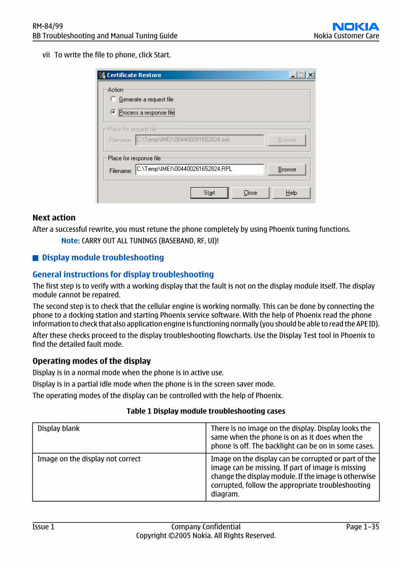
vii To write the file to phone, click Start.
Next actionAfter a successful rewrite, you must retune the phone completely by using Phoenix tuning functions.
Note: CARRY OUT ALL TUNINGS (BASEBAND, RF, UI)!
Display module troubleshooting
General instructions for display troubleshootingThe first step is to verify with a working display that the fault is not on the display module itself. The displaymodule cannot be repaired.
The second step is to check that the cellular engine is working normally. This can be done by connecting thephone to a docking station and starting Phoenix service software. With the help of Phoenix read the phoneinformation to check that also application engine is functioning normally (you should be able to read the APE ID).
After these checks proceed to the display troubleshooting flowcharts. Use the Display Test tool in Phoenix tofind the detailed fault mode.
Operating modes of the displayDisplay is in a normal mode when the phone is in active use.
Display is in a partial idle mode when the phone is in the screen saver mode.
The operating modes of the display can be controlled with the help of Phoenix.
Table 1 Display module troubleshooting cases
Display blank There is no image on the display. Display looks thesame when the phone is on as it does when thephone is off. The backlight can be on in some cases.
Image on the display not correct Image on the display can be corrupted or part of theimage can be missing. If part of image is missingchange the display module. If the image is otherwisecorrupted, follow the appropriate troubleshootingdiagram.
RM-84/99BB Troubleshooting and Manual Tuning Guide Nokia Customer Care
Issue 1 Company Confidential Page 1–35Copyright ©2005 Nokia. All Rights Reserved.
Backlight dim or not working at all Backlight LED components are inside the displaymodule. Backlight failure can also be in the connectoror in the backlight power source in the main engineof the phone. Backlight is also controlledautomatically by the ambient light sensor.
This means that in case the display is working (imageOK) but the backlight is not, follow the Display andkeyboard backlight troubleshooting (Page 1–38).
Visual defects (pixel) Pixel defects can be checked by controlling thedisplay with Phoenix. Use both colours, black andwhite, on a full screen.
The display may have some random pixel defects thatare acceptable for this type of display. The criteriawhen pixel defects are regarded as a display failure,resulting in a replacement of the display, arepresented the table below.
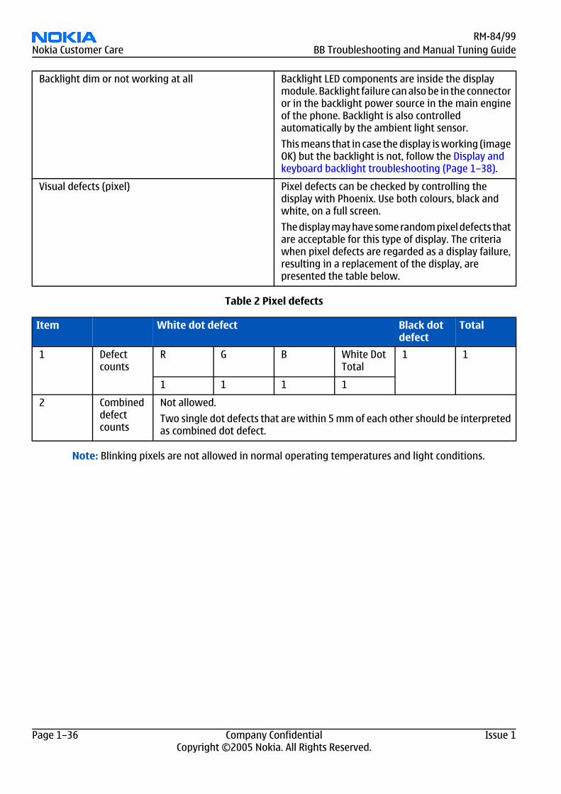
Table 2 Pixel defects
Item White dot defect Black dotdefect
Total
1 Defectcounts
R G B White DotTotal
1 1
1 1 1 1
2 Combineddefectcounts
Not allowed.
Two single dot defects that are within 5 mm of each other should be interpretedas combined dot defect.
Note: Blinking pixels are not allowed in normal operating temperatures and light conditions.
RM-84/99Nokia Customer Care BB Troubleshooting and Manual Tuning Guide
Page 1–36 Company Confidential Issue 1Copyright ©2005 Nokia. All Rights Reserved.
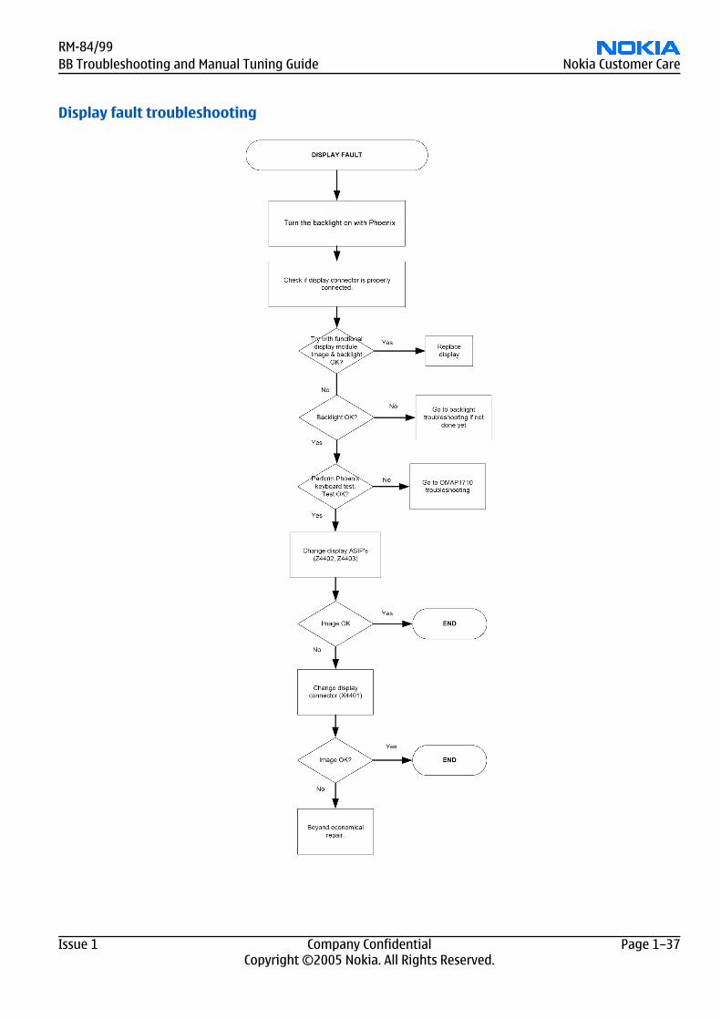
Display fault troubleshooting
RM-84/99BB Troubleshooting and Manual Tuning Guide Nokia Customer Care
Issue 1 Company Confidential Page 1–37Copyright ©2005 Nokia. All Rights Reserved.
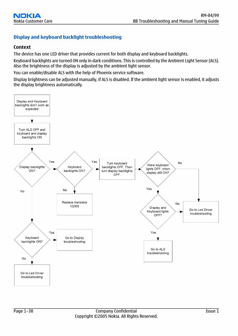
Display and keyboard backlight troubleshooting
ContextThe device has one LED driver that provides current for both display and keyboard backlights.
Keyboard backlights are turned ON only in dark conditions. This is controlled by the Ambient Light Sensor (ALS).Also the brightness of the display is adjusted by the ambient light sensor.
You can enable/disable ALS with the help of Phoenix service software.
Display brightness can be adjusted manually, if ALS is disabled. If the ambient light sensor is enabled, it adjuststhe display brightness automatically.
RM-84/99Nokia Customer Care BB Troubleshooting and Manual Tuning Guide
Page 1–38 Company Confidential Issue 1Copyright ©2005 Nokia. All Rights Reserved.
ALS troubleshooting
Context• If a phototransistor is broken, replace it with a typical phototransistor.• The phototransistor has to be also replaced, if calibration values are lost by some other reason (e.g. after
replacing the NOR memory chip D3000).• If the phototransistor is changed, the calibration value in the phone memory has to be changed to the default
value ‘1’.• Make sure that you have completed Display and keypad backlight troubleshooting (Page 1–38) first before
starting ALS troubleshooting.
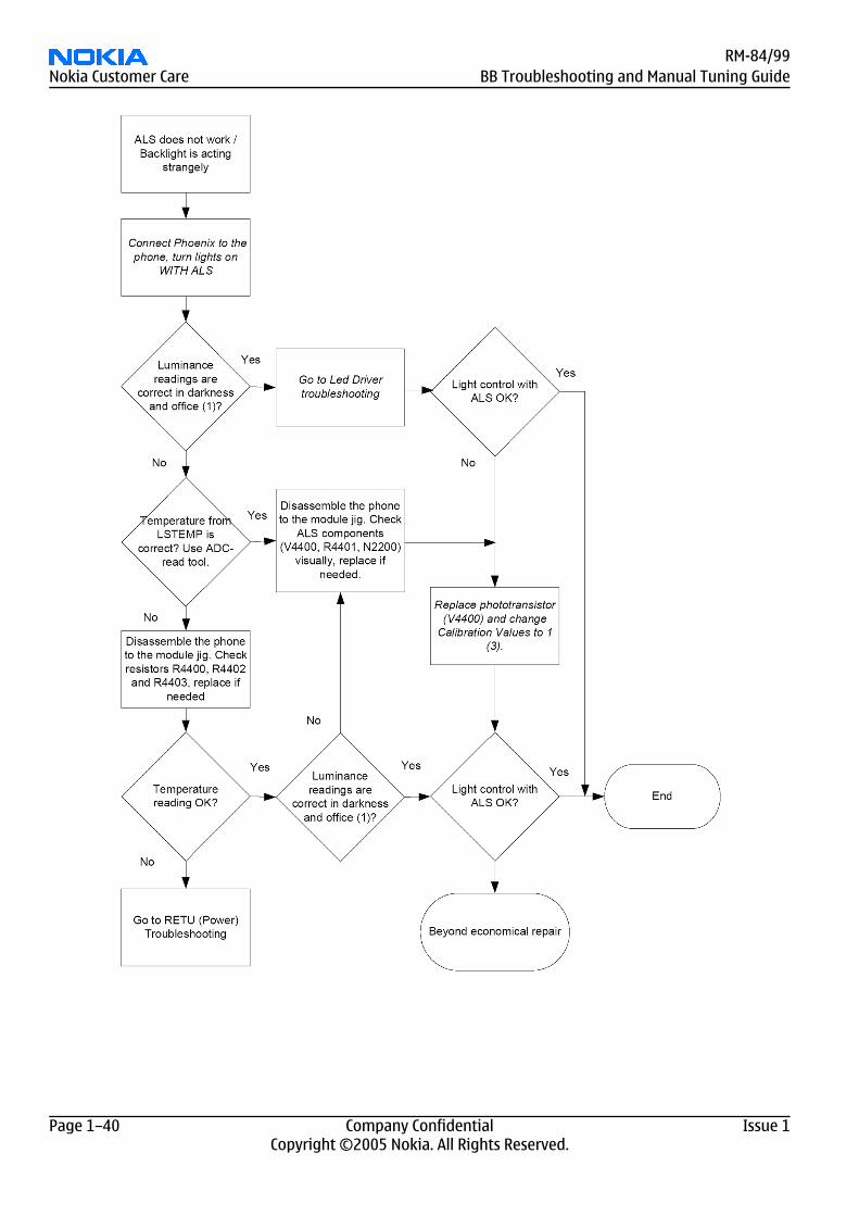
Here are some hints for ALS troubleshooting; the following troubleshooting diagram refers to these:
• Phoenix LED control tool also shows you luminance. The correct luminance in darkness is <20lx, and in officeenvironment 100-2000lx. The luminance value depends strongly on the light source and the angle of thephone, so these values are only a rough guideline.
• LED driver control voltage measurement points can be found from LED driver troubleshooting (Page1–41) section. When backlight brightness is set to 100%, both GENOUT-signals are low, and enable PWM is100%.
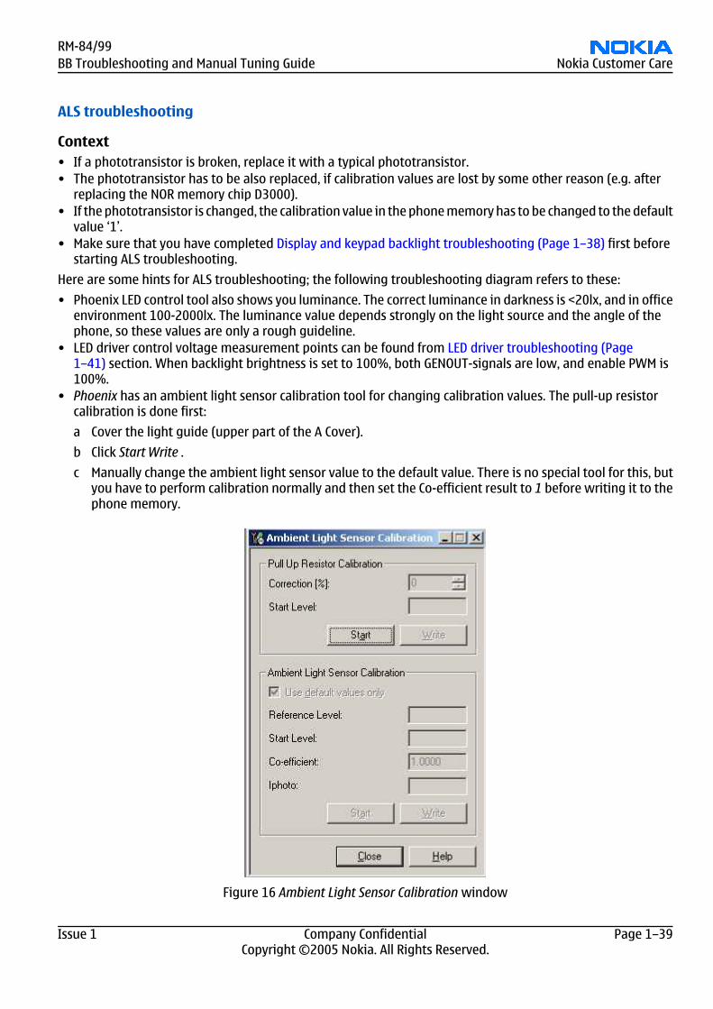
• Phoenix has an ambient light sensor calibration tool for changing calibration values. The pull-up resistorcalibration is done first:
a Cover the light guide (upper part of the A Cover).
b Click Start Write .
c Manually change the ambient light sensor value to the default value. There is no special tool for this, butyou have to perform calibration normally and then set the Co-efficient result to 1 before writing it to thephone memory.
Figure 16 Ambient Light Sensor Calibration window
RM-84/99BB Troubleshooting and Manual Tuning Guide Nokia Customer Care
Issue 1 Company Confidential Page 1–39Copyright ©2005 Nokia. All Rights Reserved.
RM-84/99Nokia Customer Care BB Troubleshooting and Manual Tuning Guide
Page 1–40 Company Confidential Issue 1Copyright ©2005 Nokia. All Rights Reserved.
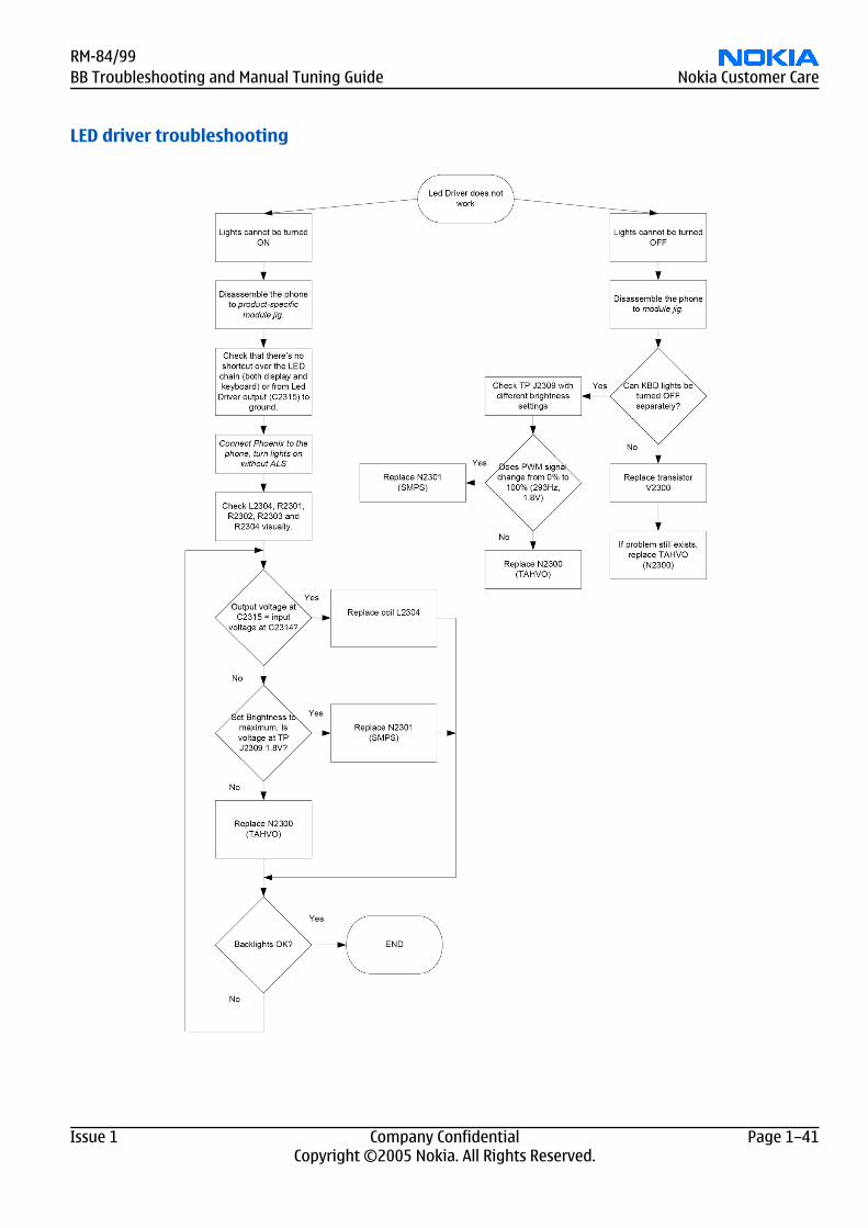
LED driver troubleshooting
RM-84/99BB Troubleshooting and Manual Tuning Guide Nokia Customer Care
Issue 1 Company Confidential Page 1–41Copyright ©2005 Nokia. All Rights Reserved.
Bluetooth troubleshooting
Introduction to Bluetooth troubleshootingThere are two main Bluetooth problems that can occur:
Problem Description
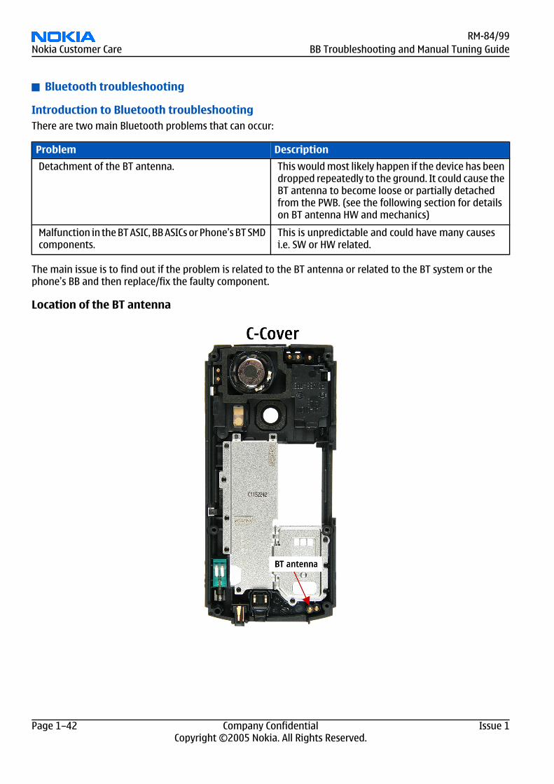
Detachment of the BT antenna. This would most likely happen if the device has beendropped repeatedly to the ground. It could cause theBT antenna to become loose or partially detachedfrom the PWB. (see the following section for detailson BT antenna HW and mechanics)
Malfunction in the BT ASIC, BB ASICs or Phone’s BT SMDcomponents.
This is unpredictable and could have many causesi.e. SW or HW related.
The main issue is to find out if the problem is related to the BT antenna or related to the BT system or thephone’s BB and then replace/fix the faulty component.
Location of the BT antenna
RM-84/99Nokia Customer Care BB Troubleshooting and Manual Tuning Guide
Page 1–42 Company Confidential Issue 1Copyright ©2005 Nokia. All Rights Reserved.
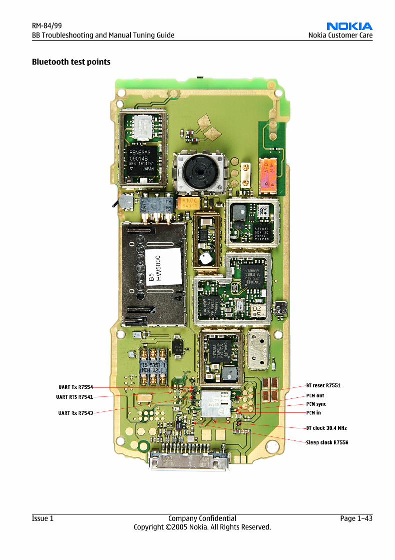
Bluetooth test points
RM-84/99BB Troubleshooting and Manual Tuning Guide Nokia Customer Care
Issue 1 Company Confidential Page 1–43Copyright ©2005 Nokia. All Rights Reserved.
Bluetooth settings for Phoenix
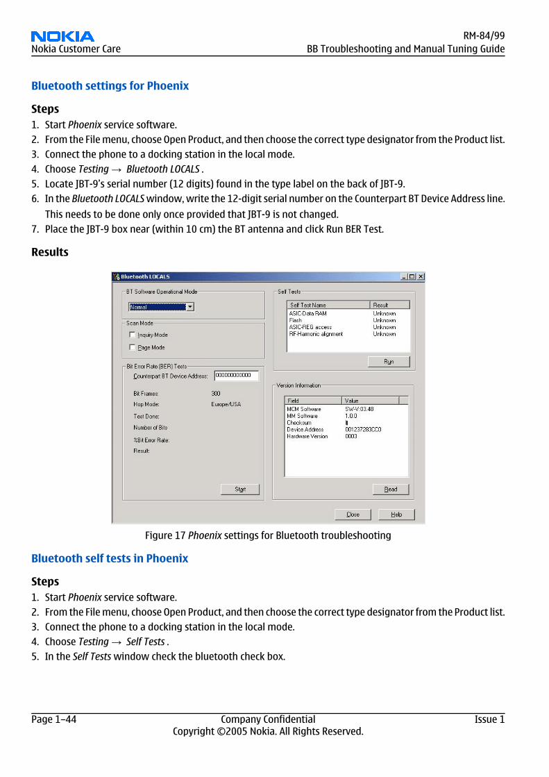
Steps1. Start Phoenix service software.2. From the File menu, choose Open Product, and then choose the correct type designator from the Product list.3. Connect the phone to a docking station in the local mode.4. Choose Testing → Bluetooth LOCALS .5. Locate JBT-9’s serial number (12 digits) found in the type label on the back of JBT-9.6. In the Bluetooth LOCALS window, write the 12-digit serial number on the Counterpart BT Device Address line.
This needs to be done only once provided that JBT-9 is not changed.7. Place the JBT-9 box near (within 10 cm) the BT antenna and click Run BER Test.
Results
Figure 17 Phoenix settings for Bluetooth troubleshooting
Bluetooth self tests in Phoenix
Steps1. Start Phoenix service software.2. From the File menu, choose Open Product, and then choose the correct type designator from the Product list.3. Connect the phone to a docking station in the local mode.4. Choose Testing → Self Tests .5. In the Self Tests window check the bluetooth check box.
RM-84/99Nokia Customer Care BB Troubleshooting and Manual Tuning Guide
Page 1–44 Company Confidential Issue 1Copyright ©2005 Nokia. All Rights Reserved.
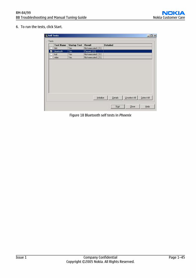
6. To run the tests, click Start.
Figure 18 Bluetooth self tests in Phoenix
RM-84/99BB Troubleshooting and Manual Tuning Guide Nokia Customer Care
Issue 1 Company Confidential Page 1–45Copyright ©2005 Nokia. All Rights Reserved.
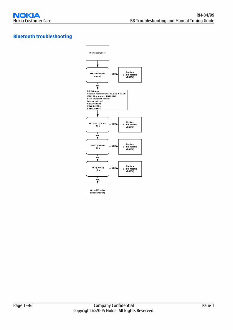
Bluetooth troubleshooting
RM-84/99Nokia Customer Care BB Troubleshooting and Manual Tuning Guide
Page 1–46 Company Confidential Issue 1Copyright ©2005 Nokia. All Rights Reserved.
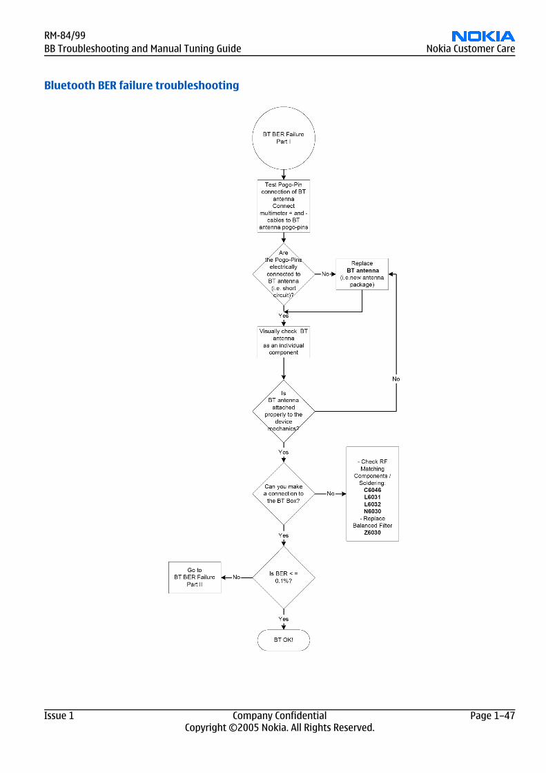
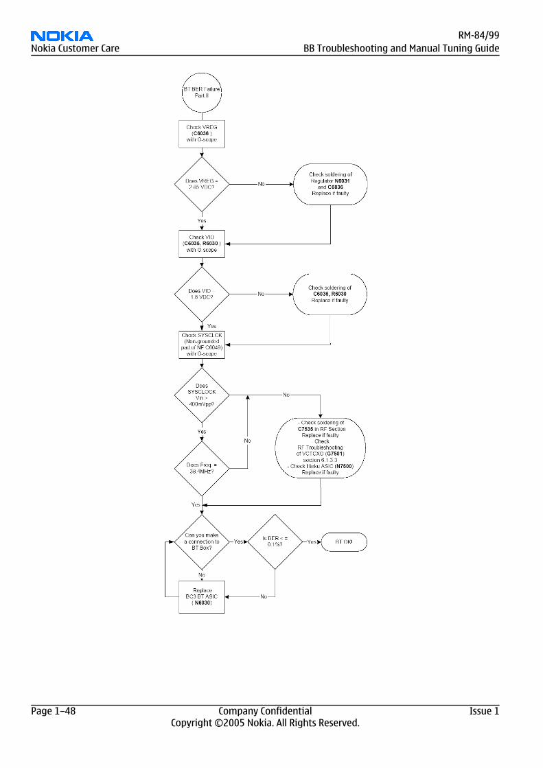
Bluetooth BER failure troubleshooting
RM-84/99BB Troubleshooting and Manual Tuning Guide Nokia Customer Care
Issue 1 Company Confidential Page 1–47Copyright ©2005 Nokia. All Rights Reserved.
RM-84/99Nokia Customer Care BB Troubleshooting and Manual Tuning Guide
Page 1–48 Company Confidential Issue 1Copyright ©2005 Nokia. All Rights Reserved.
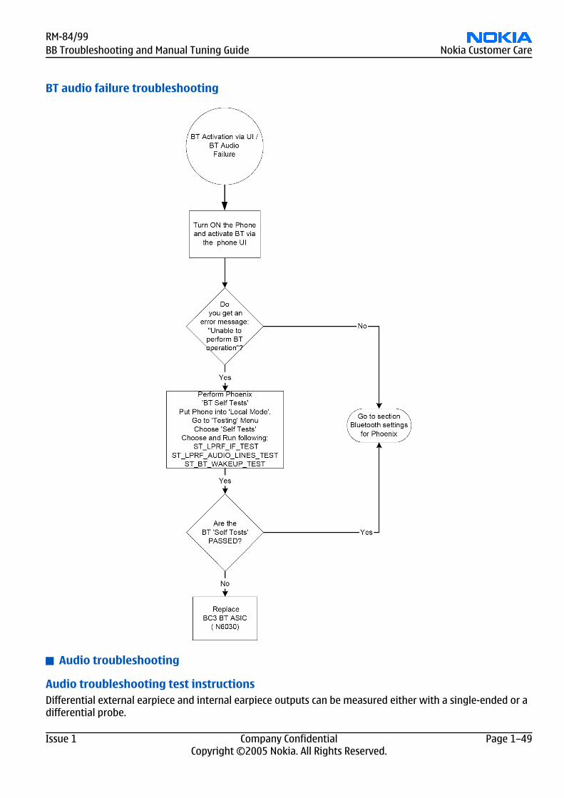
BT audio failure troubleshooting
Audio troubleshooting
Audio troubleshooting test instructionsDifferential external earpiece and internal earpiece outputs can be measured either with a single-ended or adifferential probe.
RM-84/99BB Troubleshooting and Manual Tuning Guide Nokia Customer Care
Issue 1 Company Confidential Page 1–49Copyright ©2005 Nokia. All Rights Reserved.
When measuring with a single-ended probe each output is measured against the ground.
Internal handsfree output is measured using a current probe, if a special low-pass filter designed for measuringa digital amplifier is not available. Note also that when using a current probe, the input signal frequency mustbe set to 2kHz.
The input signal for each loop test can be either single-ended or differential.
Required equipmentThe following equipment is needed for the tests:
• Oscilloscope• Function generator (sine waveform)• Current probe (Internal handsfree DPMA output measurement)• Phoenix service software• Battery voltage 3.7V
Test procedureAudio can be tested using the Phoenix audio routings option. Three different audio loop paths can be activated:
• External microphone to Internal earpiece• External microphone to Internal handsfree speaker• Internal microphone to External earpiece
Each audio loop sets routing from the specified input to the specified output enabling a quick in-out test. Looppath gains are fixed and they cannot be changed using Phoenix. Correct pins and signals for each test arepresented in the following table.
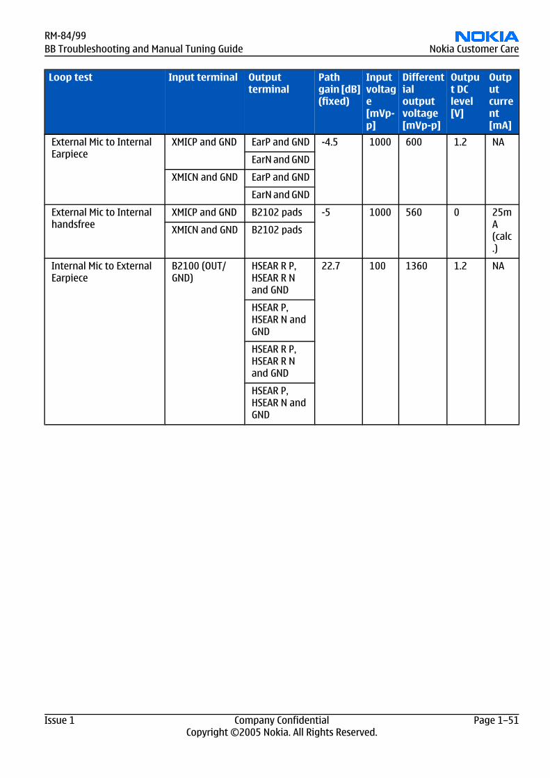
Phoenix audio loop tests and test resultsThe results presented in the table apply when no accessory is connected and battery voltage is set to 3.7V.
Earpiece, internal microphone and speaker are in place during measurement. Applying a headset accessoryduring measurement causes a significant drop in measured quantities.
The gain values presented in the table apply for a differential output vs. single-ended/differential input.
Loop test Input terminal Outputterminal
Pathgain [dB](fixed)
Inputvoltage[mVp-p]
Differentialoutputvoltage[mVp-p]
Output DClevel[V]
Outputcurrent[mA]
External Mic to ExternalEarpiece
XMICP and GND HSEAR R P,HSEAR R Nand GND
-2.9 1000 720 1.2 NA
HSEAR P,HSEAR N andGND
XMICN and GND HSEAR R P,HSEAR R Nand GND
HSEAR P,HSEAR N andGND
RM-84/99Nokia Customer Care BB Troubleshooting and Manual Tuning Guide
Page 1–50 Company Confidential Issue 1Copyright ©2005 Nokia. All Rights Reserved.
Loop test Input terminal Outputterminal
Pathgain [dB](fixed)
Inputvoltage[mVp-p]
Differentialoutputvoltage[mVp-p]
Output DClevel[V]
Outputcurrent[mA]
External Mic to InternalEarpiece
XMICP and GND EarP and GND -4.5 1000 600 1.2 NA
EarN and GND
XMICN and GND EarP and GND
EarN and GND
External Mic to Internalhandsfree
XMICP and GND B2102 pads -5 1000 560 0 25mA(calc.)
XMICN and GND B2102 pads
Internal Mic to ExternalEarpiece
B2100 (OUT/GND)
HSEAR R P,HSEAR R Nand GND
22.7 100 1360 1.2 NA
HSEAR P,HSEAR N andGND
HSEAR R P,HSEAR R Nand GND
HSEAR P,HSEAR N andGND
RM-84/99BB Troubleshooting and Manual Tuning Guide Nokia Customer Care
Issue 1 Company Confidential Page 1–51Copyright ©2005 Nokia. All Rights Reserved.
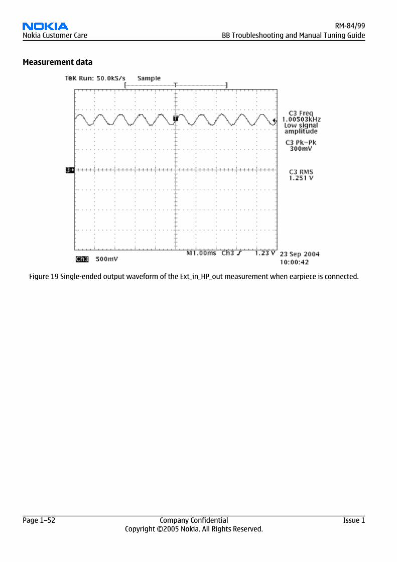
Measurement data
Figure 19 Single-ended output waveform of the Ext_in_HP_out measurement when earpiece is connected.
RM-84/99Nokia Customer Care BB Troubleshooting and Manual Tuning Guide
Page 1–52 Company Confidential Issue 1Copyright ©2005 Nokia. All Rights Reserved.
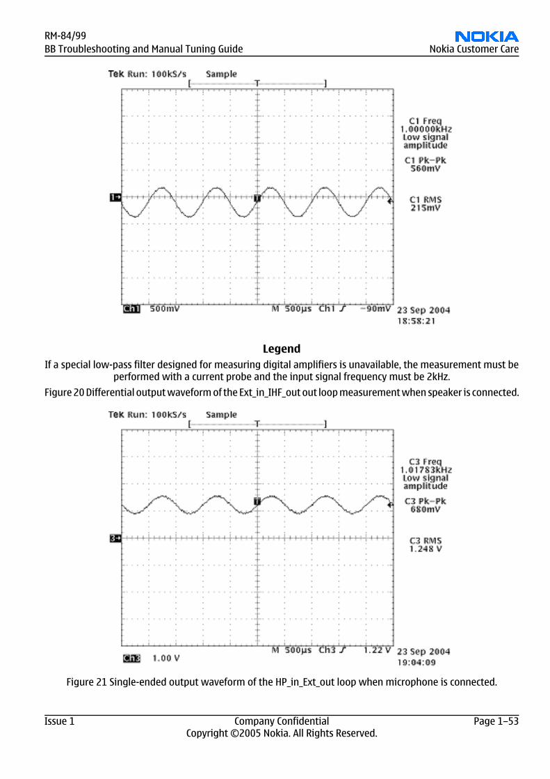
LegendIf a special low-pass filter designed for measuring digital amplifiers is unavailable, the measurement must be
performed with a current probe and the input signal frequency must be 2kHz.
Figure 20 Differential output waveform of the Ext_in_IHF_out out loop measurement when speaker is connected.
Figure 21 Single-ended output waveform of the HP_in_Ext_out loop when microphone is connected.
RM-84/99BB Troubleshooting and Manual Tuning Guide Nokia Customer Care
Issue 1 Company Confidential Page 1–53Copyright ©2005 Nokia. All Rights Reserved.
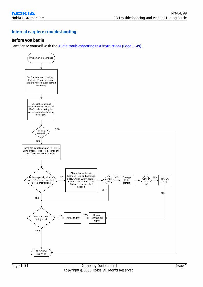
Internal earpiece troubleshooting
Before you beginFamiliarize yourself with the Audio troubleshooting test instructions (Page 1–49).
RM-84/99Nokia Customer Care BB Troubleshooting and Manual Tuning Guide
Page 1–54 Company Confidential Issue 1Copyright ©2005 Nokia. All Rights Reserved.
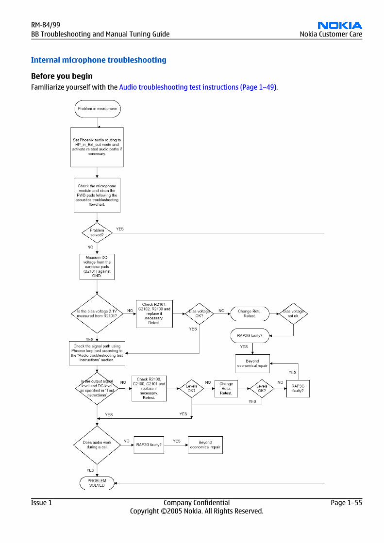
Internal microphone troubleshooting
Before you beginFamiliarize yourself with the Audio troubleshooting test instructions (Page 1–49).
RM-84/99BB Troubleshooting and Manual Tuning Guide Nokia Customer Care
Issue 1 Company Confidential Page 1–55Copyright ©2005 Nokia. All Rights Reserved.
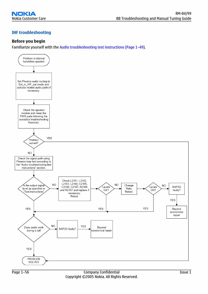
IHF troubleshooting
Before you beginFamiliarize yourself with the Audio troubleshooting test instructions (Page 1–49).
RM-84/99Nokia Customer Care BB Troubleshooting and Manual Tuning Guide
Page 1–56 Company Confidential Issue 1Copyright ©2005 Nokia. All Rights Reserved.
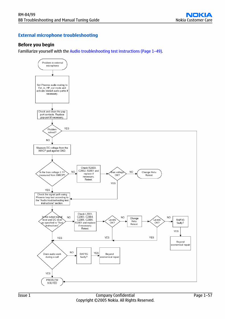
External microphone troubleshooting
Before you beginFamiliarize yourself with the Audio troubleshooting test instructions (Page 1–49).
RM-84/99BB Troubleshooting and Manual Tuning Guide Nokia Customer Care
Issue 1 Company Confidential Page 1–57Copyright ©2005 Nokia. All Rights Reserved.
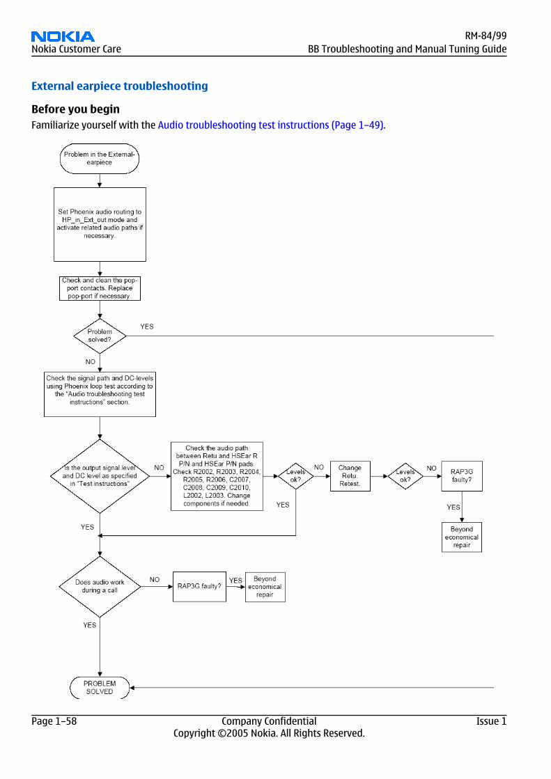
External earpiece troubleshooting
Before you beginFamiliarize yourself with the Audio troubleshooting test instructions (Page 1–49).
RM-84/99Nokia Customer Care BB Troubleshooting and Manual Tuning Guide
Page 1–58 Company Confidential Issue 1Copyright ©2005 Nokia. All Rights Reserved.
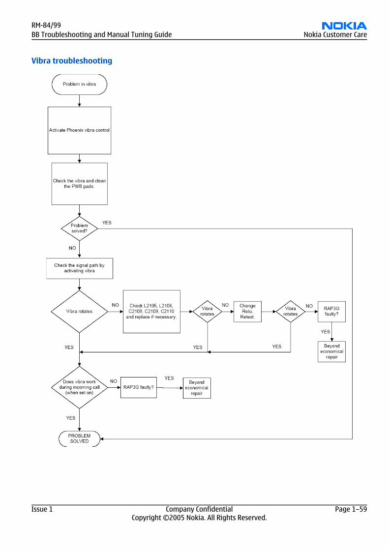
Vibra troubleshooting
RM-84/99BB Troubleshooting and Manual Tuning Guide Nokia Customer Care
Issue 1 Company Confidential Page 1–59Copyright ©2005 Nokia. All Rights Reserved.
Baseband manual tuning guide
Energy management calibration
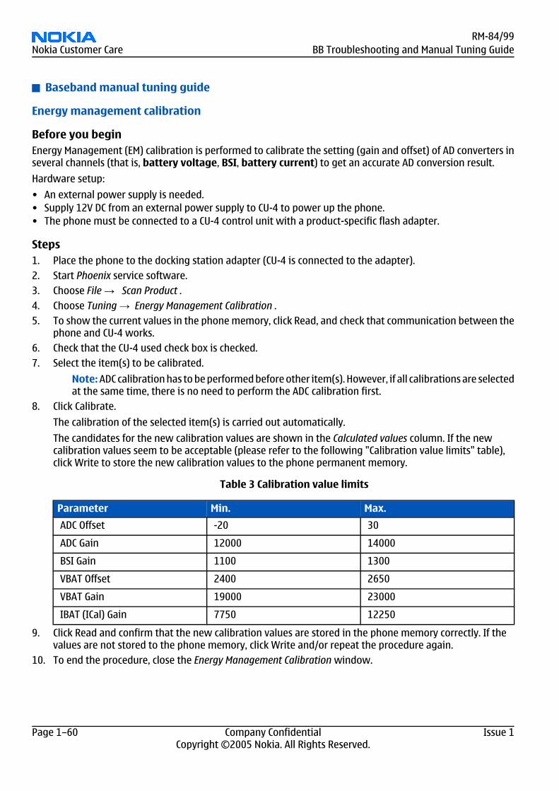
Before you beginEnergy Management (EM) calibration is performed to calibrate the setting (gain and offset) of AD converters inseveral channels (that is, battery voltage, BSI, battery current) to get an accurate AD conversion result.
Hardware setup:
• An external power supply is needed.• Supply 12V DC from an external power supply to CU-4 to power up the phone.• The phone must be connected to a CU-4 control unit with a product-specific flash adapter.
Steps1. Place the phone to the docking station adapter (CU-4 is connected to the adapter).2. Start Phoenix service software.3. Choose File → Scan Product .4. Choose Tuning → Energy Management Calibration .5. To show the current values in the phone memory, click Read, and check that communication between the
phone and CU-4 works.6. Check that the CU-4 used check box is checked.7. Select the item(s) to be calibrated.
Note: ADC calibration has to be performed before other item(s). However, if all calibrations are selectedat the same time, there is no need to perform the ADC calibration first.
8. Click Calibrate.
The calibration of the selected item(s) is carried out automatically.
The candidates for the new calibration values are shown in the Calculated values column. If the newcalibration values seem to be acceptable (please refer to the following "Calibration value limits" table),click Write to store the new calibration values to the phone permanent memory.
Table 3 Calibration value limits
Parameter Min. Max.
ADC Offset -20 30
ADC Gain 12000 14000
BSI Gain 1100 1300
VBAT Offset 2400 2650
VBAT Gain 19000 23000
IBAT (ICal) Gain 7750 12250
9. Click Read and confirm that the new calibration values are stored in the phone memory correctly. If thevalues are not stored to the phone memory, click Write and/or repeat the procedure again.
10. To end the procedure, close the Energy Management Calibration window.
RM-84/99Nokia Customer Care BB Troubleshooting and Manual Tuning Guide
Page 1–60 Company Confidential Issue 1Copyright ©2005 Nokia. All Rights Reserved.
![Oracle Database Mobile Server Troubleshooting and Tuning …[1]Oracle® Database Mobile Server Troubleshooting and Tuning Guide Release 12.1.0 E58643-01 January 2015](https://img.pdfslide.us/doc/110x75/60c86c1beff138714b73f779/oracle-database-mobile-server-troubleshooting-and-tuning-1oracle-database-mobile.jpg)