Embed Size (px)
Citation preview

NOKIA M2M GATEWAY 2.2
SERVICE PROVIDER EDITION ADMINISTRATION MANUAL
Cop
yrig
ht ©
200
2-20
03 N
okia
. All
right
s re
serv
ed.
Iss
ue 3
.0
935
7457
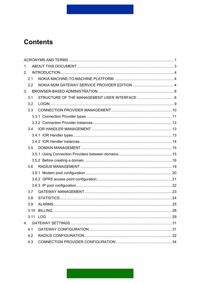
Contents
ACRONYMS AND TERMS ......................................................................................................1 1. ABOUT THIS DOCUMENT ..............................................................................................3 2. INTRODUCTION..............................................................................................................4
2.1 NOKIA MACHINE-TO-MACHINE PLATFORM ..........................................................4 2.2 NOKIA M2M GATEWAY SERVICE PROVIDER EDITION ........................................4
3. BROWSER-BASED ADMINISTRATION..........................................................................8 3.1 STRUCTURE OF THE MANAGEMENT USER INTERFACE....................................8 3.2 LOGIN ........................................................................................................................9 3.3 CONNECTION PROVIDER MANAGEMENT...........................................................10
3.3.1 Connection Provider types ...................................................................................11 3.3.2 Connection Provider instances.............................................................................12
3.4 IOR HANDLER MANAGEMENT ..............................................................................13 3.4.1 IOR Handler types................................................................................................13 3.4.2 IOR Handler instances .........................................................................................14
3.5 DOMAIN MANAGEMENT ........................................................................................15 3.5.1 Using Connection Providers between domains....................................................15 3.5.2 Before creating a domain .....................................................................................16
3.6 RADIUS MANAGEMENT .........................................................................................19 3.6.1 Modem pool configuration ....................................................................................20 3.6.2 GPRS access point configuration.........................................................................21 3.6.3 IP pool configuration.............................................................................................22
3.7 GATEWAY MANAGEMENT.....................................................................................23 3.8 STATISTICS.............................................................................................................24 3.9 ALARMS...................................................................................................................25 3.10 BILLING....................................................................................................................28 3.11 LOG .....................................................................................................................29
4. GATEWAY SETTINGS ..................................................................................................31 4.1 GATEWAY CONFIGURATION ................................................................................31 4.2 RADIUS CONFIGURATION.....................................................................................32 4.3 CONNECTION PROVIDER CONFIGURATION ......................................................34
4.3.1 WAP GPRS Connection Provider ........................................................................36 4.3.2 WAP SMS Connection Provider...........................................................................38 4.3.3 WAP USSD Connection Provider.........................................................................40 4.3.4 WAP CSD Connection Provider ...........................................................................42 4.3.5 WAP Serial CSD Connection Provider.................................................................43 4.3.6 Wake-up Connection Provider .............................................................................46 4.3.7 SmartMessaging Connection Provider.................................................................48 4.3.8 Text Message Connection Provider .....................................................................50 4.3.9 Endpoint and driver properties .............................................................................53
4.3.9.1 UDP endpoint parameters ............................................................................53 4.3.9.2 SMS endpoint parameters............................................................................54 4.3.9.3 Serial CSD endpoint parameters..................................................................55 4.3.9.4 CIMD20 driver parameters ...........................................................................56 4.3.9.5 SMPP driver parameters ..............................................................................56 4.3.9.6 UCP driver parameters.................................................................................58 4.3.9.7 WAP driver parameters ................................................................................58
4.3.10 IIOP Connection Provider.....................................................................................59 4.3.11 Tunnel Connection Provider.................................................................................62 4.3.12 SSL Tunnel Connection Provider .........................................................................63
4.4 IOR HANDLER CONFIGURATION..........................................................................65 4.5 DOMAIN CONFIGURATION....................................................................................67 4.6 ERROR HANDLING AND TROUBLESHOOTING ...................................................70
5. SSL TUNNELLING.........................................................................................................71 6. GATEWAY SERVICES ..................................................................................................72
6.1 INTRODUCTION......................................................................................................72 6.2 AUTHENTICATION AND ACCESS CONTROL.......................................................73 6.3 STATISTICS SERVICE............................................................................................73 6.4 ALARM SERVICE ....................................................................................................73 6.5 LOG SERVICE .........................................................................................................74 6.6 BILLING SERVICE...................................................................................................75
APPENDIX .............................................................................................................................77 1. ALARM DESCRIPTIONS ...............................................................................................77
1.1 CORE ALARMS – 1000 TO 3000 AREA..................................................................77 1.2 CONNECTION PROVIDER ALARMS - 4000 AREA................................................78

1.3 BILLING ALARMS – 5000 AREA .............................................................................79 2. STATISTICS DESCRIPTIONS.......................................................................................79
2.1 COMMON CONNECTION PROVIDER STATISTICS ..............................................79 2.2 SPECIFIC CONNECTION PROVIDER STATISTICS ..............................................80
3. REDUNDANT SERVICE PROVIDING...........................................................................82 4. PARAMETERS AND EXAMPLE CONFIGURATION.....................................................82
4.1 PARAMETERS.........................................................................................................82 4.2 EXAMPLE CONFIGURATION WITH THE NOKIA GSM CONNECTIVITY
TERMINAL CONFIGURATOR .................................................................................85 4.2.1 General settings ...................................................................................................85 4.2.2 Settings for wireless bearers ................................................................................87
4.2.2.1 No bearer......................................................................................................87 4.2.2.2 HSCSD/CSD settings ...................................................................................88 4.2.2.3 SMS settings ................................................................................................90 4.2.2.4 GPRS settings..............................................................................................91 4.2.2.5 USSD settings ..............................................................................................94
5. EXAMPLE CONFIGURATION OF THE GATEWAY FOR DATACALL USAGE ............95 5.1 SETTING UP THE CONNECTION PROVIDERS ....................................................96
5.1.1 Installing the Connection Provider types ..............................................................97 5.1.2 Loading and configuring the Connection Provider instances ...............................97 5.1.3 Activating the Connection Provider instances ......................................................99
5.2 SETTING UP THE IOR HANDLER ..........................................................................99 5.2.1 Installing the IOR Handler type ..........................................................................100 5.2.2 Loading and configuring the IOR Handler instance............................................100 5.2.3 Activating the IOR Handler instance ..................................................................100
5.3 SETTING UP THE DOMAIN ..................................................................................100 5.3.1 Creating the domain ...........................................................................................101 5.3.2 Configuring the domain ......................................................................................101 5.3.3 Activating the domain .........................................................................................102
5.4 SETTING UP THE RADIUS SERVER ...................................................................102 5.4.1 RADIUS Server configuration.............................................................................102 5.4.2 Configuring the modem pool ..............................................................................102 5.4.3 Configuring the IP pool.......................................................................................103 5.4.4 Configuring the route and Cisco 3620................................................................104

5.4.4.1 Making the route definition in Windows......................................................104 5.4.4.2 Configuring Cisco 3620 ..............................................................................104
5.5 CONFIGURING THE GATEWAY ACCESS SOFTWARE......................................104 5.5.1 Installing credentials for the SSL connection .....................................................105 5.5.2 Configuring the Gateway address ......................................................................105 5.5.3 Configuring the Device Information Storage reference implementation.............105
Legal Notice
Copyright © 2002-2003 Nokia. All rights reserved.
Reproduction, transfer, distribution or storage of part or all of the contents in this document in any form without the prior written permission of Nokia is prohibited.
Nokia and Nokia Connecting People are registered trademarks of Nokia Corporation. Java and all Java-based marks are trademarks or registered trademarks of Sun Microsystems, Inc. Other product and company names mentioned herein may be trademarks or trade names of their respective owners.
Nokia operates a policy of continuous development. Nokia reserves the right to make changes and improvements to any of the products described in this document without prior notice.
Under no circumstances shall Nokia be responsible for any loss of data or income or any special, incidental, consequential or indirect damages howsoever caused.
The contents of this document are provided "as is". Except as required by applicable law, no warranties of any kind, either express or implied, including, but not limited to, the implied warranties of merchantability and fitness for a particular purpose, are made in relation to the accuracy, reliability or contents of this document. Nokia reserves the right to revise this document or withdraw it at any time without prior notice.

1/105
ACRONYMS AND TERMS
Acronym/term Description
ACK Acknowledge character
AM Application Module
CIMD Computer Interface for Message Distribution
CP Connection Provider
CSD Circuit Switched Data
CSV Comma Separated Value
CORBA Common Object Request Broker Architecture
DIS Device Information Storage
DNS Domain Name Server
GGSN Gateway GPRS Service Node
GIOP General Inter-ORB Protocol
GPRS General Packet Radio Service
GSM Global Digital System for Mobile Communications
HSCSD High Speed Circuit Switched Data
IDL Interface Definition Language
IIOP Internet Inter-ORB Protocol
IOR Interoperable Object Reference
IP Internet Protocol
JDBC Java™ Database Connectivity
JSP™ JavaServer Pages™
LAN Local Area Network
M2M Machine-to-Machine
MSISDN Mobile Subscriber International ISDN Number
NAT Network Address Translator
NS Naming Service
OMG Object Management Group
ORB Object Request Broker
RADIUS Remote Authentication Dial-in User Service /Server
SMPP Short Message Peer-to-Peer Protocol
SMS Short Message Service
2/105
Acronym/term Description
SMSC Short Message Service Centre
SSL Secure Sockets Layer
TCP Transport Control Protocol
TID Transaction Identifier
UCP Universal Control Protocol
UI User Interface
USSD Unstructured Supplementary Service Data
VPN Virtual Private Network
WAP Wireless Application Protocol
WIOP Wireless Inter-ORB Protocol
WTP Wireless Transaction Protocol

3/105
1. ABOUT THIS DOCUMENT
This document provides the basic information you need to configure, manage, and monitor the Nokia M2M Gateway Service Provider Edition.
4/105
2. INTRODUCTION
2.1 NOKIA MACHINE-TO-MACHINE PLATFORM The Nokia M2M Platform enables seamless interaction between wireless and Internet hosts. The Platform consists of a wireless terminal developed specifically for embedded application use, and the Gateway capable of establishing GSM connections using multiple bearers such as GPRS, CSD, HSCSD, SMS and USSD.
Note: The availability of GSM bearers (GPRS, CSD, HSCSD, SMS and USSD) depends on the network operator and the GSM network. Contact your network operator for further information and availability.
AM(HW+SW)
Method calls Serverapplication
Nokia GSMConnectivity
Terminal WIOP
Nokia M2MGateway ServiceProvide Edition IIOP
Gateway Access
Software
Figure 1. Nokia M2M Platform
Either the remote application or the server application can initiate communications. The Gateway or the terminal establishes the wireless connection as required. Protocol translation and optimisation for the wireless link is carried out at the Gateway. Terminals and the application module of the customer are provided with software for the platform usage.
The Gateway provides wireless Common Object Request Broker Architecture (CORBA) access to and interoperability with the Internet. The wireless bearer optimised Wireless Inter-ORB Protocol (WIOP) is translated into the standard CORBA Internet Inter-ORB Protocol (IIOP) that is used in Internet applications.
2.2 NOKIA M2M GATEWAY SERVICE PROVIDER EDITION The Gateway features further operation support on behalf of client companies. The architecture consists of one Gateway maintained by the service provider, and of several domains with Gateway Access Software maintained by customer companies.

5/105
Each client company can operate its domain within a system that is capable of self-managing terminal databases. CORBA requests are routed - on the basis of the domain name - from the Gateway to the Gateway Access Software of the given domain, and from the domain to specific terminals via the following bearers:
• Circuit Switched Data (CSD)
• High Speed Circuit Switched Data (HSCSD)
• Short Message Service (SMS)
• General Packet Radio Service (GPRS)
• Unstructured Supplementary Service Data (USSD) The use of these bearers requires network support. For further information and availability contact your network operator.
CSD/HSCSD Using CSD or HSCSD as a wireless bearer requires a modem or modem pool support from the network operator. Customers may acquire their own modem pool in which case it may also be used for other dial-up access.
SMS Using SMS as a wireless bearer requires connection to the Short Message Service Centre (SMSC) of the network operator. Other requirements are as follows:
• Supported protocols: CIMD 2.0, SMPP 3.3 – 3.4, UCP 3.2 – 3.5.
• Supported connection types: TCP/IP over modem or Local Area Network (LAN)
• Normal text messaging support from the Gateway in addition to sending data messages to terminals
GPRS Using GPRS as a wireless bearer requires a connection to the Gateway GPRS Service Node (GGSN) of the network operator. Other requirements are as follows:
• Supported protocol: Compatible GGSN with support for external RADIUS server and dynamic IP address allocation. For example current Nokia GGSN is capable of this.
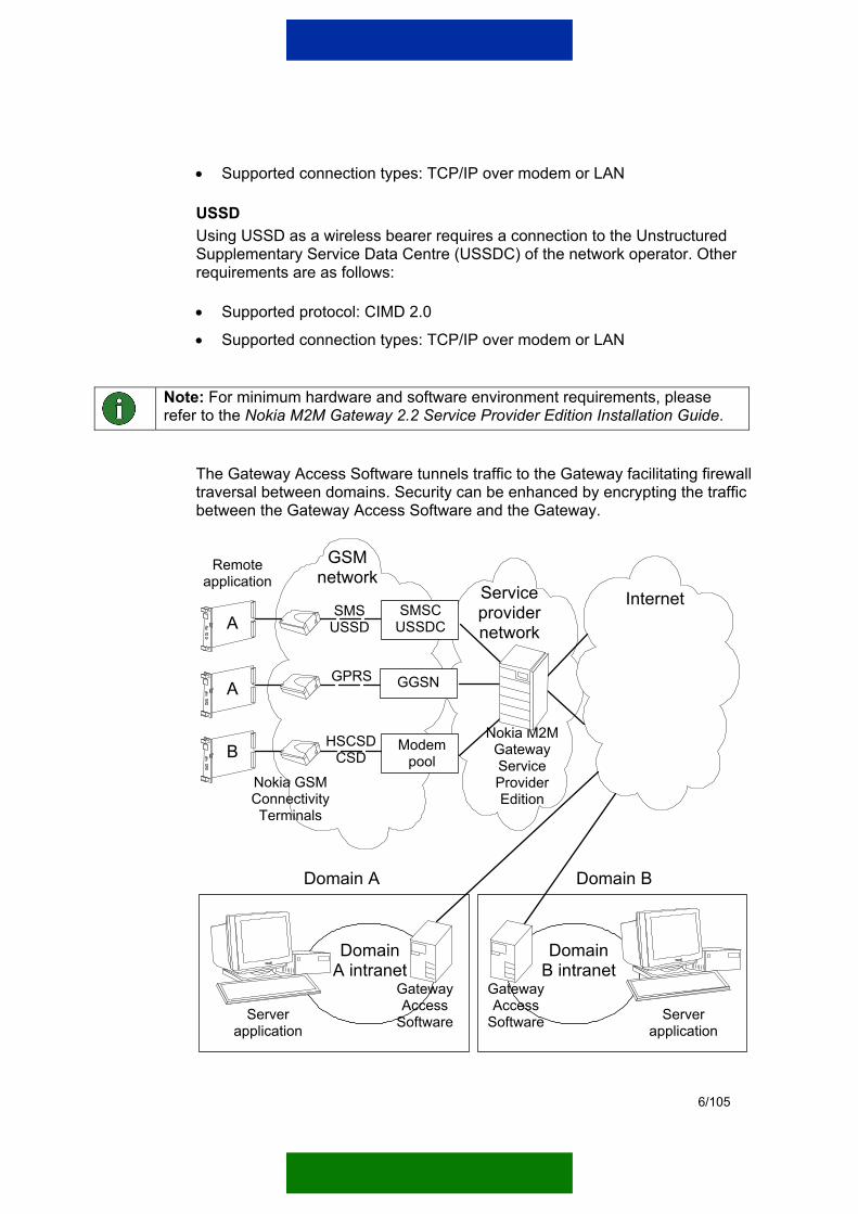
6/105
• Supported connection types: TCP/IP over modem or LAN
USSD Using USSD as a wireless bearer requires a connection to the Unstructured Supplementary Service Data Centre (USSDC) of the network operator. Other requirements are as follows:
• Supported protocol: CIMD 2.0
• Supported connection types: TCP/IP over modem or LAN
Note: For minimum hardware and software environment requirements, please refer to the Nokia M2M Gateway 2.2 Service Provider Edition Installation Guide.
The Gateway Access Software tunnels traffic to the Gateway facilitating firewall traversal between domains. Security can be enhanced by encrypting the traffic between the Gateway Access Software and the Gateway.
Remote application
Nokia GSMConnectivity Terminals
InternetA
A
B
GSMnetwork
SMSUSSD
SMSCUSSDC
GPRS GGSN
Modempool
HSCSDCSD
Nokia M2MGatewayServiceProviderEdition
DomainB intranet
Domain B
DomainA intranet
Serverapplication
Domain A
Serverapplication
Serviceprovidernetwork
Gateway Access
Software
Gateway Access
Software
7/105
Figure 2. Architecture of the Nokia M2M Gateway Service Provider Edition
The Gateway forwards Remote Authentication Dial-In User Service (RADIUS) to particular domains that are connected to it via secure connections such as Virtual Private Network (VPN) or Secure Sockets Layer (SSL).
8/105
3. BROWSER-BASED ADMINISTRATION
The main tasks of administration are the configuration of the Gateway and management of alarms, statistics and log information.
Administration is handled via a browser-based Nokia M2M Gateway Management User Interface (UI). Using the Management UI for administration offers increased security because the system checks any changes that are made, and indicates if the entered new values are invalid.
There are two kinds of users in the system: an administrator who has access to all actions, and normal users who have access to only some parts of the system. The administrator can configure the gateway’s parameter and person who has user rights can only view the parameters.
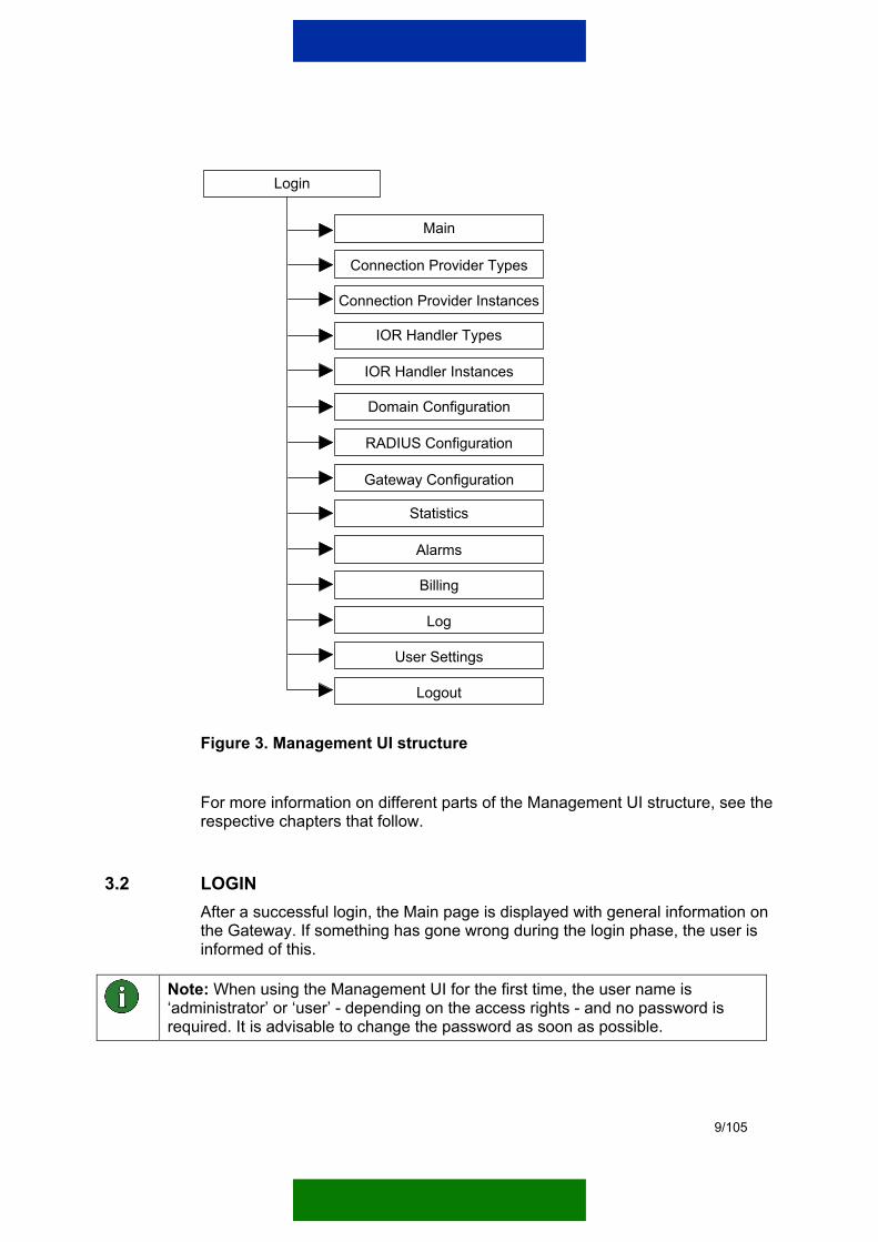
3.1 STRUCTURE OF THE MANAGEMENT USER INTERFACE The user must always log into the Management UI system. After a successful login, the main page of the Management UI displays general information on the Gateway. On the right side of the window there is a menu that helps the user to navigate in the Management UI. Figure 3 shows the general structure of the Management UI.
9/105
Login
Main
Connection Provider Types
Connection Provider Instances
IOR Handler Types
IOR Handler Instances
Domain Configuration
RADIUS Configuration
Gateway Configuration
Statistics
Log
User Settings
Logout
Billing
Alarms
Figure 3. Management UI structure
For more information on different parts of the Management UI structure, see the respective chapters that follow.
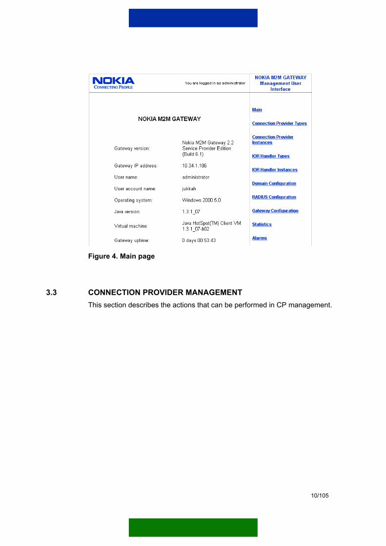
3.2 LOGIN After a successful login, the Main page is displayed with general information on the Gateway. If something has gone wrong during the login phase, the user is informed of this.
Note: When using the Management UI for the first time, the user name is ‘administrator’ or ‘user’ - depending on the access rights - and no password is required. It is advisable to change the password as soon as possible.
10/105
Figure 4. Main page
3.3 CONNECTION PROVIDER MANAGEMENT This section describes the actions that can be performed in CP management.

11/105
3.3.1 Connection Provider types
Figure 5. CP types
Installing a new CP type A new CP type can be installed via the Install new CP type link. When the link is clicked, a page is displayed where you can browse for the path of the CP to be installed.
Loading a new CP instance By clicking the Load new instance link of the installed CP type, you can load a new CP instance. During this action, you must define an instance name for the CP. When you click the Load button, the CP instance is loaded and the configuration of the loaded CP instance is displayed. If you change any of the parameter values, click the Save button to save the new values. Otherwise, click the Back link. The loaded CP instance is displayed in the list of ‘Inactive CP instances’.
Note: It is not possible to load multiple CP instances of the same installed CP type and version.
Uninstalling a CP type By clicking the Uninstall CP type link, you can permanently remove the installed CP type from the system.
Note: The CP instances of a given CP type and version must be unloaded and deactivated before the CP type can be uninstalled.
12/105
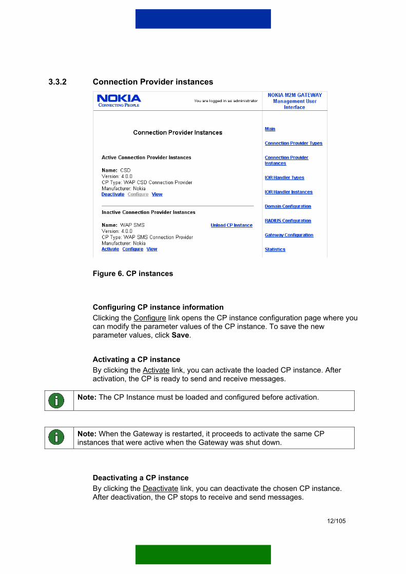
3.3.2 Connection Provider instances
Figure 6. CP instances
Configuring CP instance information Clicking the Configure link opens the CP instance configuration page where you can modify the parameter values of the CP instance. To save the new parameter values, click Save.
Activating a CP instance By clicking the Activate link, you can activate the loaded CP instance. After activation, the CP is ready to send and receive messages.
Note: The CP Instance must be loaded and configured before activation.
Note: When the Gateway is restarted, it proceeds to activate the same CP instances that were active when the Gateway was shut down.
Deactivating a CP instance By clicking the Deactivate link, you can deactivate the chosen CP instance. After deactivation, the CP stops to receive and send messages.

13/105
Unloading a CP instance By clicking the Unload link, you can unload the chosen CP instance. This action erases instance information from the system.
Note: The CP instance must be deactivated before unloading can be done.
3.4 IOR HANDLER MANAGEMENT This section describes the actions that can be performed in Interoperable Object Reference (IOR) Handler management.
3.4.1 IOR Handler types
Figure 7. IOR Handler types
Installing a new IOR Handler type A new IOR Handler type can be installed via the Install new IOR Handler type link. When you click the link, a page is displayed where you can browse for the path of the IOR Handler to be installed.
Loading a new IOR Handler instance By clicking the Load new instance link, you can load a new IOR Handler instance. During this action, you must define an instance name for the IOR Handler. When you click the Load button, the IOR Handler instance is loaded and displayed in the list of ‘Inactive IOR Handler instances’.
Note: The IOR Handler type must be installed before loading the IOR Handler instance. It is advisable to install only one IOR Handler instance for one IOR
14/105
Handler type, because the first found IOR Handler instance is always used.
Uninstalling an IOR Handler type By clicking the Uninstall link, you can remove the installed IOR Handler type from the system.
Note: The IOR Handler instance of a given IOR Handler type must be unloaded and deactivated before the IOR Handler type can be uninstalled.
3.4.2 IOR Handler instances
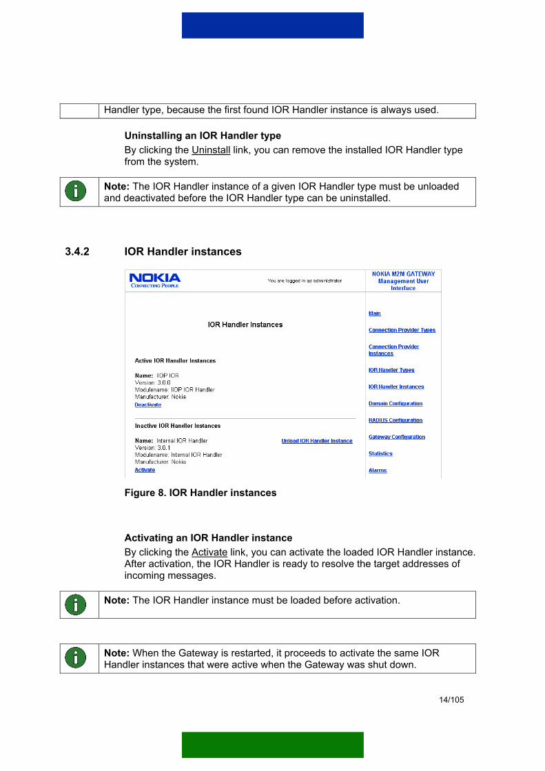
Figure 8. IOR Handler instances
Activating an IOR Handler instance By clicking the Activate link, you can activate the loaded IOR Handler instance. After activation, the IOR Handler is ready to resolve the target addresses of incoming messages.
Note: The IOR Handler instance must be loaded before activation.
Note: When the Gateway is restarted, it proceeds to activate the same IOR Handler instances that were active when the Gateway was shut down.
15/105
Deactivating an IOR Handler instance By clicking the Deactivate link, you can deactivate the chosen IOR Handler instance. After deactivation, the IOR Handler stops to resolve the target addresses of incoming messages.
Unloading an IOR Handler instance By clicking the Unload link, you can unload the chosen IOR Handler instance. This action erases instance information from the system.
Note: The IOR Handler instance must be deactivated before unloading.
3.5 DOMAIN MANAGEMENT This section describes the actions that can be performed in domain management. For more information on domain configuration, refer to Chapter 4.5.
3.5.1 Using Connection Providers between domains The CP usage of different domains should be planned. For example, there should be more than one WAP SMS CP to balance load and traffic. The need to optimise grows as the number of domains and amount of communication increases.
Table 1 presents an example situation of how the domains can be configured when the service provider services 5 different domains.
Table 1. An example of how CP usage is divided among domains
CP Domain 1 Domain 2 Domain 3 Domain 4 Domain 5
SMS 1 CP x X
GPRS 1 CP X x
CSD 1 CP x x
SMS 2 CP X x
SMS 3 CP x
CSD 2 CP X X x
As can be seen from Table 1, different domains can use the same CP.
Figure 9 illustrates the CP use of domains 1 and 2 according to Table 1.

16/105
Domain 1
Domain 1
Domain 2
Nokia M2MGateway ServiceProvider Edition
GPRS 1 CP
SMS 1 CP
CSD 1 CP
CSD 2 CP
Domain 1
Domain 2
Gateway Access Softwares
Figure 9. An example of CP use by two different domains
3.5.2 Before creating a domain This section explains the steps that need to be followed in order to build communication between the service provider and the Gateway Access Software of the client.
All the required IOR Handlers, IP pools, and CPs need to be installed, activated, and configured, and the service provider needs to create all the necessary domains.
IOR Handlers All IOR Handlers that are to be used must be installed and activated.
IP pool Each modem pool and GPRS access point that is to be used must have its IP pool defined because pools and address areas cannot be changed when the Gateway has been activated. These must be configured before any CPs can be assigned to use.
Connection Providers The following CPs are available:
• WAP GPRS CP (requires an own IP pool)
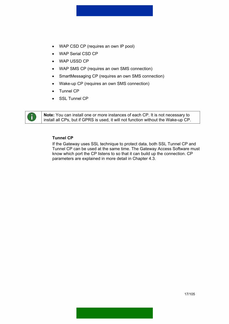
17/105
• WAP CSD CP (requires an own IP pool)
• WAP Serial CSD CP
• WAP USSD CP
• WAP SMS CP (requires an own SMS connection)
• SmartMessaging CP (requires an own SMS connection)
• Wake-up CP (requires an own SMS connection)
• Tunnel CP
• SSL Tunnel CP
Note: You can install one or more instances of each CP. It is not necessary to install all CPs, but if GPRS is used, it will not function without the Wake-up CP.
Tunnel CP If the Gateway uses SSL technique to protect data, both SSL Tunnel CP and Tunnel CP can be used at the same time. The Gateway Access Software must know which port the CP listens to so that it can build up the connection. CP parameters are explained in more detail in Chapter 4.3.
18/105
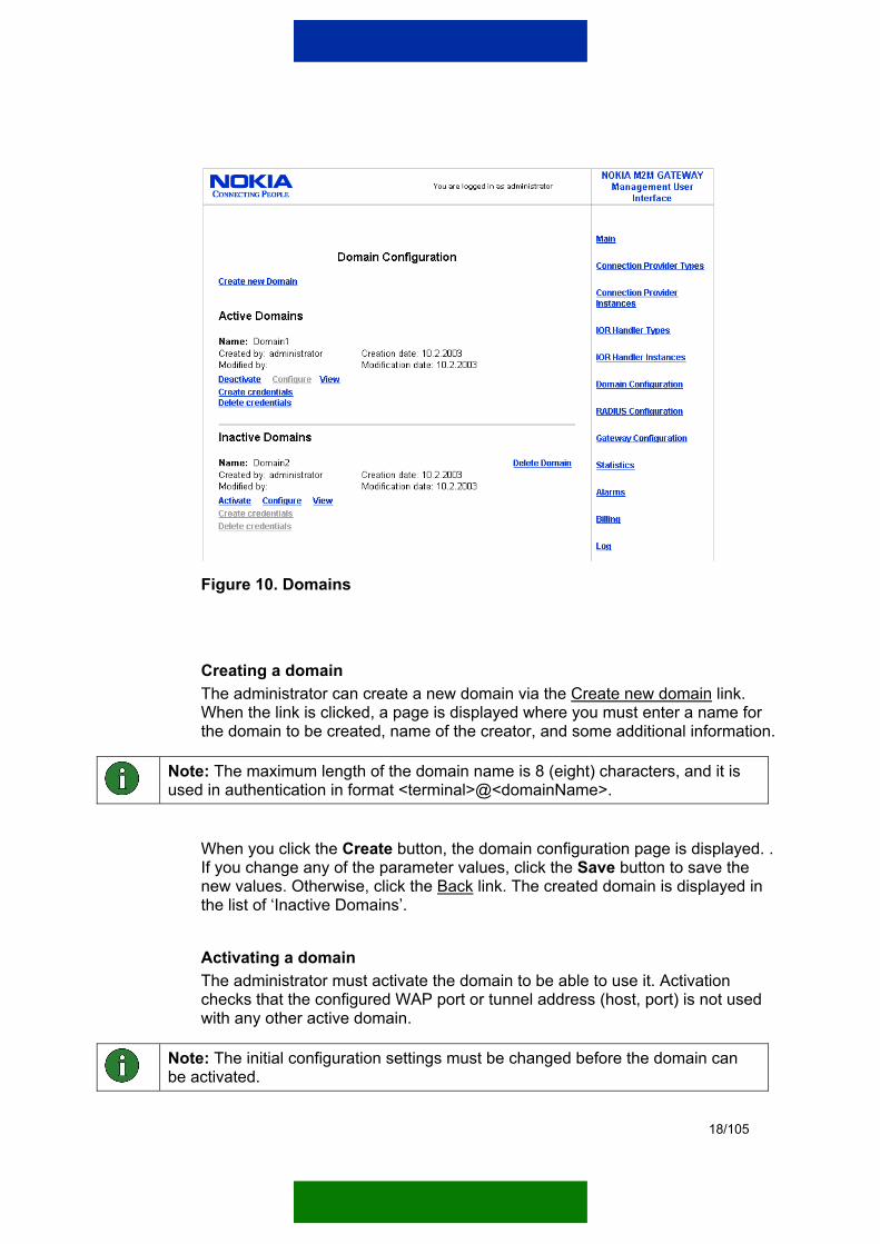
Figure 10. Domains
Creating a domain The administrator can create a new domain via the Create new domain link. When the link is clicked, a page is displayed where you must enter a name for the domain to be created, name of the creator, and some additional information.
Note: The maximum length of the domain name is 8 (eight) characters, and it is used in authentication in format <terminal>@<domainName>.
When you click the Create button, the domain configuration page is displayed. . If you change any of the parameter values, click the Save button to save the new values. Otherwise, click the Back link. The created domain is displayed in the list of ‘Inactive Domains’.
Activating a domain The administrator must activate the domain to be able to use it. Activation checks that the configured WAP port or tunnel address (host, port) is not used with any other active domain.
Note: The initial configuration settings must be changed before the domain can be activated.

19/105
By clicking the Activate link, you can activate the created domain. When the domain is activated, the Gateway sends messages to and receives them from the domain.
Deactivating a domain By clicking the Deactivate link, the administrator can deactivate the chosen domain. After deactivation, no messages are sent to or received from this domain.
Deleting a domain The administrator can delete a domain when it is no longer required.
Note: The domain must be deactivated before it can be deleted.
By clicking the Uninstall link, the administrator can remove the created domain from the system.
Create credentials By clicking the Create credentials link, new credentials can be created for domains that are new or already in use if SSL is used in communication.
Delete credentials By clicking the Delete credentials link, the created credentials can be deleted.
Note: For more information on SSL tunnelling and SSL credentials, please refer to Chapter 5 and the Nokia M2M Gateway Gateway Access Software 2.2 Administration Manual.
3.6 RADIUS MANAGEMENT The RADIUS parameters are handled from the RADIUS Configuration page. For more information on RADIUS parameters, see Chapter 4.2.

20/105
Figure 11. RADIUS Configuration page
To modify the RADIUS Server parameters, click the Configure RADIUS Server link to open the editing page (see Figure 11).
3.6.1 Modem pool configuration To modify the modem pool parameters, click the Configure modem pool link to open the editing page (see Figure 12).

21/105
Figure 12. Modem pool configuration
3.6.2 GPRS access point configuration To modify the GPRS access point parameters, click the Configure GPRS access point link to open the editing page (see Figure 13).
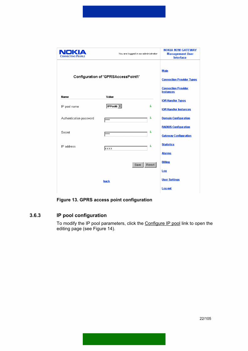
22/105
Figure 13. GPRS access point configuration
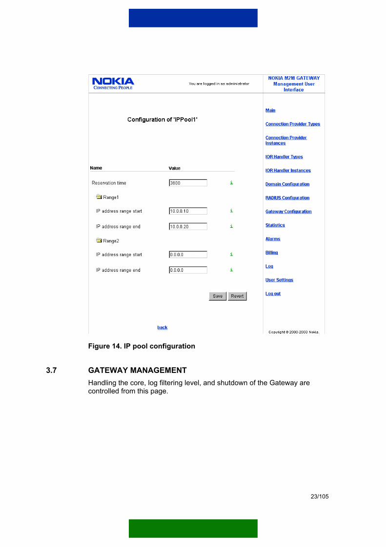
3.6.3 IP pool configuration To modify the IP pool parameters, click the Configure IP pool link to open the editing page (see Figure 14).
23/105
Figure 14. IP pool configuration
3.7 GATEWAY MANAGEMENT Handling the core, log filtering level, and shutdown of the Gateway are controlled from this page.
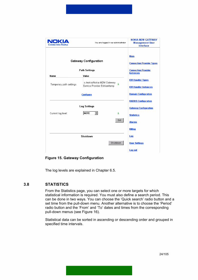
24/105
Figure 15. Gateway Configuration
The log levels are explained in Chapter 6.5.
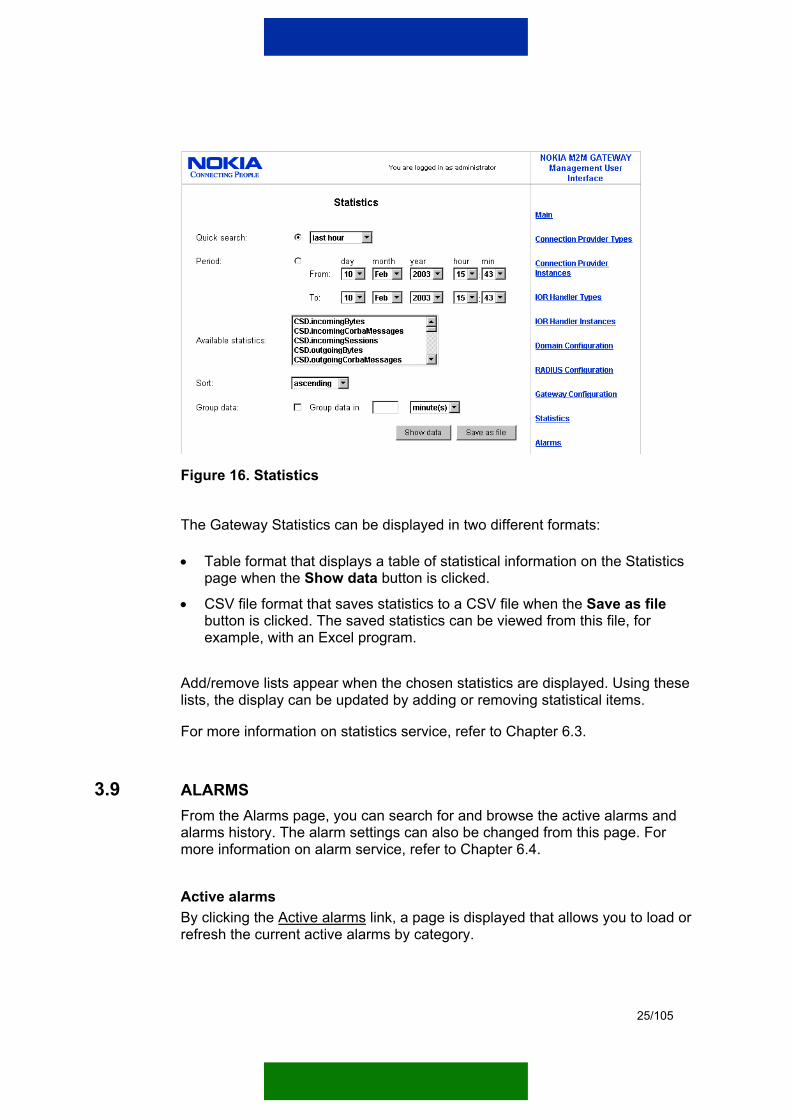
3.8 STATISTICS From the Statistics page, you can select one or more targets for which statistical information is required. You must also define a search period. This can be done in two ways. You can choose the ‘Quick search’ radio button and a set time from the pull-down menu. Another alternative is to choose the ‘Period’ radio button and the ‘From’ and ‘To’ dates and times from the corresponding pull-down menus (see Figure 16).
Statistical data can be sorted in ascending or descending order and grouped in specified time intervals.
25/105
Figure 16. Statistics
The Gateway Statistics can be displayed in two different formats:
• Table format that displays a table of statistical information on the Statistics page when the Show data button is clicked.
• CSV file format that saves statistics to a CSV file when the Save as file button is clicked. The saved statistics can be viewed from this file, for example, with an Excel program.
Add/remove lists appear when the chosen statistics are displayed. Using these lists, the display can be updated by adding or removing statistical items.
For more information on statistics service, refer to Chapter 6.3.
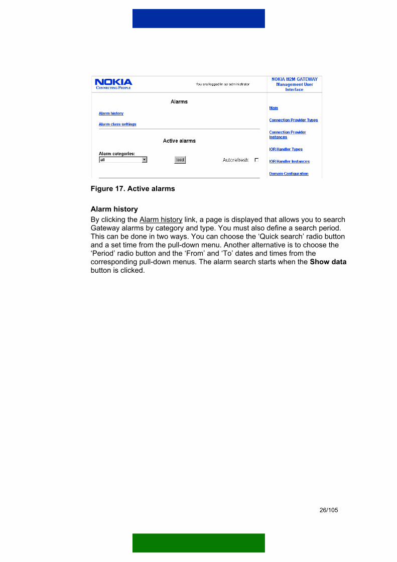
3.9 ALARMS From the Alarms page, you can search for and browse the active alarms and alarms history. The alarm settings can also be changed from this page. For more information on alarm service, refer to Chapter 6.4.
Active alarms By clicking the Active alarms link, a page is displayed that allows you to load or refresh the current active alarms by category.
26/105
Figure 17. Active alarms
Alarm history By clicking the Alarm history link, a page is displayed that allows you to search Gateway alarms by category and type. You must also define a search period. This can be done in two ways. You can choose the ‘Quick search’ radio button and a set time from the pull-down menu. Another alternative is to choose the ‘Period’ radio button and the ‘From’ and ‘To’ dates and times from the corresponding pull-down menus. The alarm search starts when the Show data button is clicked.

27/105
Figure 18. Alarm history
Alarm class settings By clicking the Alarm class settings link, a page is displayed that shows (if set) the automatic alarm cancelling information (Auto cancel), and the length of time between the occurrence and cancelling of an alarm (Auto cancel delay). To modify the Alarm class settings, click the Edit link.

28/105
Figure 19. Alarm class settings
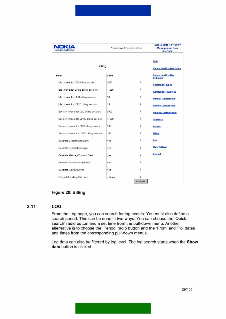
3.10 BILLING From the Billing page, you can view the current billing settings. You can also change the billing settings from this page. For more information on billing service, refer to Chapter 6.6.
To modify the billing parameters, click the Configure link.
29/105
Figure 20. Billing
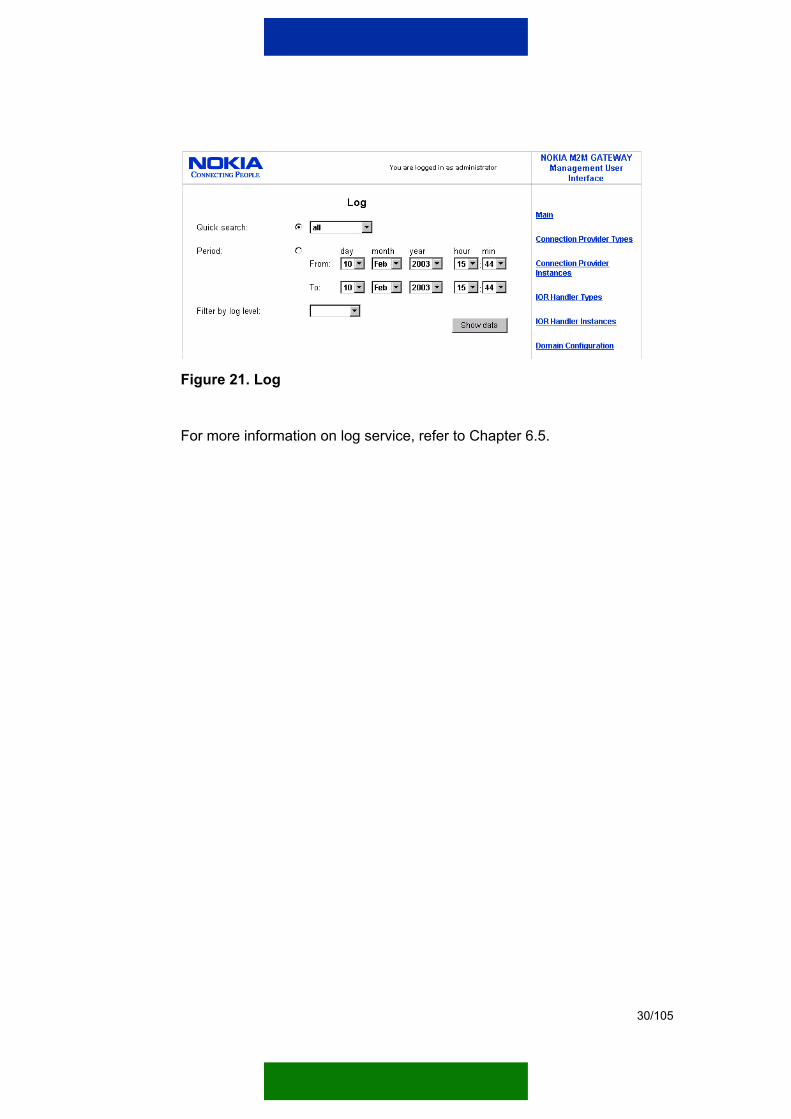
3.11 LOG From the Log page, you can search for log events. You must also define a search period. This can be done in two ways. You can choose the ‘Quick search’ radio button and a set time from the pull-down menu. Another alternative is to choose the ‘Period’ radio button and the ‘From’ and ‘To’ dates and times from the corresponding pull-down menus.
Log data can also be filtered by log level. The log search starts when the Show data button is clicked.
30/105
Figure 21. Log
For more information on log service, refer to Chapter 6.5.

31/105
4. GATEWAY SETTINGS
This chapter describes how to control and configure the Gateway settings. The following components of the Gateway have configurable parameters:
• Gateway configuration
• RADIUS configuration
• Connection Provider configuration (handles CPs that function as protocol tubes for messages)
• Domain configuration
The system administrator can limit access to the configuration information.
RADIUS configuration
Connection Provider configuration
Gateway configuration
Domain configuration
Figure 22. Gateway architecture
4.1 GATEWAY CONFIGURATION
Table 2 presents the Gateway configuration parameters.
Table 2. Gateway configuration parameters
Parameter name
Description Default value Possible value(s)
Temporary file path
Path used to save temporary files. <GW inst dir>/temp Not to be left empty.
32/105
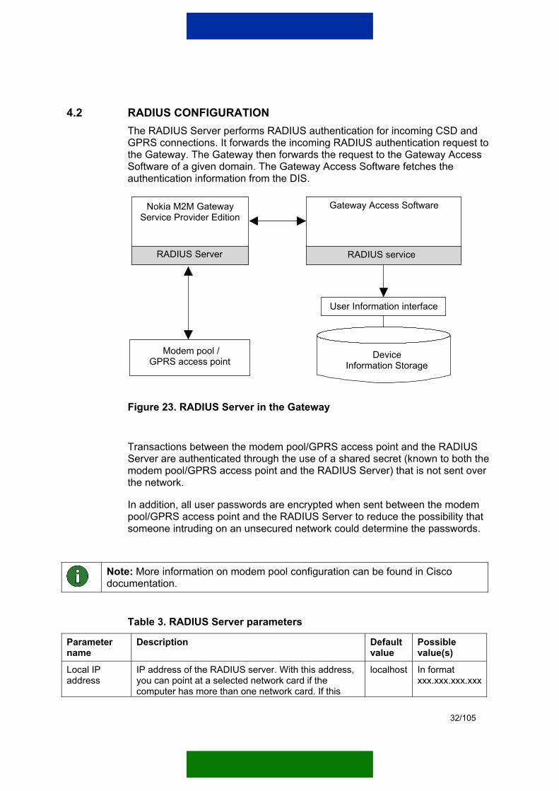
4.2 RADIUS CONFIGURATION The RADIUS Server performs RADIUS authentication for incoming CSD and GPRS connections. It forwards the incoming RADIUS authentication request to the Gateway. The Gateway then forwards the request to the Gateway Access Software of a given domain. The Gateway Access Software fetches the authentication information from the DIS.
Nokia M2M GatewayService Provider Edition
RADIUS Server
User Information interface
Gateway Access Software
RADIUS service
Modem pool /GPRS access point
Device Information Storage
Figure 23. RADIUS Server in the Gateway
Transactions between the modem pool/GPRS access point and the RADIUS Server are authenticated through the use of a shared secret (known to both the modem pool/GPRS access point and the RADIUS Server) that is not sent over the network.
In addition, all user passwords are encrypted when sent between the modem pool/GPRS access point and the RADIUS Server to reduce the possibility that someone intruding on an unsecured network could determine the passwords.
Note: More information on modem pool configuration can be found in Cisco documentation.
Table 3. RADIUS Server parameters
Parameter name
Description Default value
Possible value(s)
Local IP address
IP address of the RADIUS server. With this address, you can point at a selected network card if the computer has more than one network card. If this
localhost In format xxx.xxx.xxx.xxx

33/105
Parameter name
Description Default value
Possible value(s)
value is set to 'localhost', the RADIUS server binds to the default network interface of the system.
Authentication port
Port number of the RADIUS authentication socket. 1812 0…65535
Accounting port
Port number of the RADIUS accounting socket. 1813 0…65535
Authenticate terminals
Defines whether the Gateway requires authentication from incoming connections.
If set to 'yes', the Gateway requires authentication from all incoming connections.
If set to 'no', it suffices that the modem pool/GPRS access point informs the Gateway when the connection is opened (radius-start message) and closed (radius-stop message).
yes
yes, no
Allocate IP address
Defines whether the Gateway allocates an IP address for the terminal.
If set to 'yes', the Gateway allocates and IP address for the terminal during authentication.
If set to 'no', the Gateway expects to receive the IP address in a radius-start message.
Note! If the Allocate IP address parameter is set to 'yes', the Authenticate terminals parameter must also be set to 'yes' because the Gateway can deliver the IP address only during authentication.
yes yes, no
Table 4. Modem pool/GPRS access point parameters
Parameter name
Description Default value
Possible value(s)
Authorisation password
Password for modem pool/GPRS access point authorisation (maximum 16 characters).
**** 1…16
Secret Secret between the RADIUS Server and modem pool/GPRS access point.
**** Not to be left empty
IP address IP address of the modem pool/GPRS access point. localhost In format xxx.xxx.xxx.xxx
IP pool name Name of the IP pool associated with the modem pool/GPRS access point.
IPPool1…10

34/105
Table 5. IP pool parameters - common
Parameter name
Description Default value
Possible value(s)
Reservation time
Length of time in seconds the IP address is reserved for a certain device.
3600 0…2147483647
Table 6. IP pool parameters - first range
Parameter name
Description Default value
Possible value(s)
IP address range start
First IP address of this address range. 0.0.0.0 In format xxx.xxx.xxx.xxx
IP address range end
Last IP address of this address range. 0.0.0.0 In format xxx.xxx.xxx.xxx
Table 7. Modem pool instance settings - second range
Parameter name
Description Default value
Possible value(s)
IP address range start
First IP address of this address range. 0.0.0.0 In format xxx.xxx.xxx.xxx
IP address range end
Last IP address of this address range. 0.0.0.0 In format xxx.xxx.xxx.xxx
4.3 CONNECTION PROVIDER CONFIGURATION The Gateway has different CP types that allow the use of different protocols (SMS, CSD, GPRS, USSD) via modem pool or GPRS access point. The CP types are used to handle incoming and outgoing messages to and from the Gateway.
Note: Please note that in order for the connection to work properly the firewalls of the system and other network security elements need to allow the connection to pass through.
To use a CP type, you first need to install, load, configure, and activate it. During installation, the CP needs to know the properties of available connections so that it can be loaded into the system without stopping the Gateway.
You can load one or more CP instances for one CP type. All loaded CP instances of a given CP type have the same parameters but different configuration values.
35/105
Note: It is not possible to load multiple CP instances of the same installed CP type version.
Note: When the Gateway is restarted, it proceeds to activate the same CP instances that where active when the Gateway was shut down.
To remove a CP type, you need to deactivate, unload, and uninstall it.

36/105
4.3.1 WAP GPRS Connection Provider WAP GPRS CP provides GPRS connection from/to terminals via GPRS access point.
CP ConfigurationWAP GPRS CP
WAP SMS CP
WAP USSD CP
SmartMessaging CP
WAP CSD CP
Wake-up CP
TextMessage CP
Tunnel CP
SSL Tunnel CP
WAP Serial CSD CP
IIOP CP
Figure 24. WAP GPRS CP
Table 8. Specific configuration parameters for WAP GPRS CP
Parameter name
Description Default value
Possible value(s)
Session timeout
Length of time in seconds the session can be idle before it is closed.
Note! Advanced parameter.
8640000 1…31449600
IP pool name
Name of the used IP pool. IPPool2 IPPool1…10
Use Wake-up Service
Defines whether the Wake-up Service is used. yes yes, no
Wake-up ti t
If the Wake-up Service is used, this parameter ifi th l th f ti i d th k
60 5…3600

37/105
Parameter name
Description Default value
Possible value(s)
timeout specifies the length of time in seconds the wake-up may take.
Initial number of threads
Initial number of threads.
Note! Advanced parameter. 10 1…100
Wake-up port
Port where the wake-up messages are sent. The terminal must have a WAP SMS bearer set-up that uses this port.
1 0…65535
Wake-up bearer
When the Wake-up Service is used, this parameter sets the used wake-up bearer. The bearer must be one of the Wake-up CPs of the Wake-up Service. Type the name of the Wake-up CP here.
disabled Connection Provider name
Wake-up security time
Defines the length of time in seconds the Wake-up Service waits before it creates a new wake-up after the GPRS context has dropped. This value is used only if the Wake-up Service is enabled.
45 0…3600
Endpoint and driver parameters for WAP GPRS CP WAP GPRS CP has one endpoint: an UDP endpoint that uses WAP driver in communication (see Figure 25). The UDP endpoint and WAP driver parameters are described in Chapter 4.3.9.
WAP GPRS CP
UDPendpoint
WAP
Figure 25. Hierarchy of WAP GPRS CP
38/105
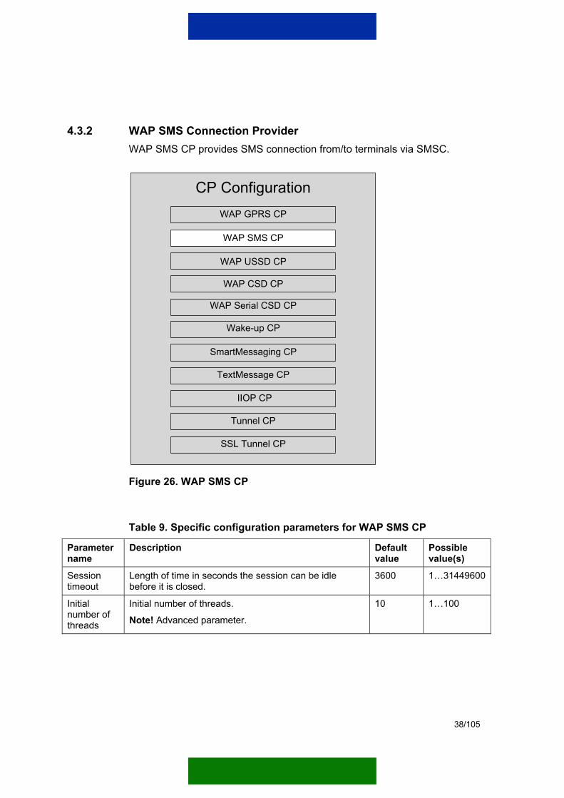
4.3.2 WAP SMS Connection Provider WAP SMS CP provides SMS connection from/to terminals via SMSC.
CP ConfigurationWAP GPRS CP
WAP SMS CP
WAP USSD CP
SmartMessaging CP
WAP CSD CP
Wake-up CP
TextMessage CP
Tunnel CP
SSL Tunnel CP
WAP Serial CSD CP
IIOP CP
Figure 26. WAP SMS CP
Table 9. Specific configuration parameters for WAP SMS CP
Parameter name
Description Default value
Possible value(s)
Session timeout
Length of time in seconds the session can be idle before it is closed.
3600 1…31449600
Initial number of threads
Initial number of threads.
Note! Advanced parameter. 10 1…100
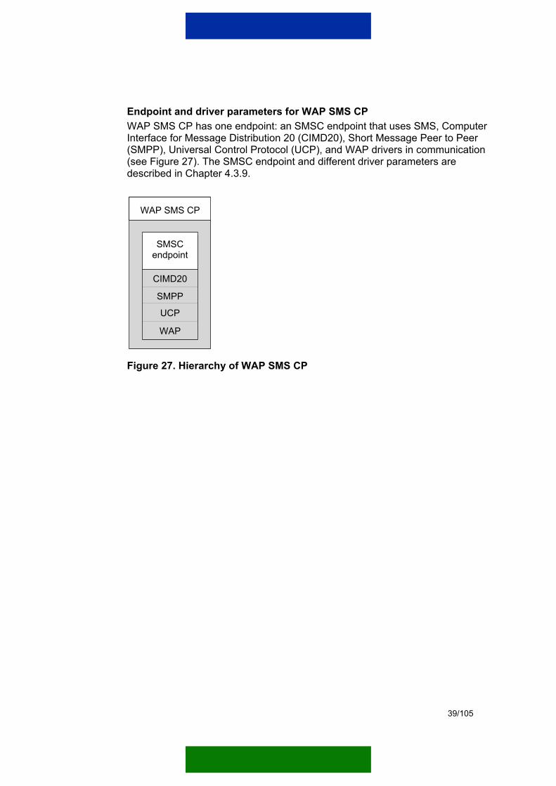
39/105
Endpoint and driver parameters for WAP SMS CP WAP SMS CP has one endpoint: an SMSC endpoint that uses SMS, Computer Interface for Message Distribution 20 (CIMD20), Short Message Peer to Peer (SMPP), Universal Control Protocol (UCP), and WAP drivers in communication (see Figure 27). The SMSC endpoint and different driver parameters are described in Chapter 4.3.9.
WAP SMS CP
CIMD20
SMSCendpoint
SMPP
UCP
WAP
Figure 27. Hierarchy of WAP SMS CP

40/105
4.3.3 WAP USSD Connection Provider WAP USSD CP provides USSD connection from/to terminals via USSDC.
CP ConfigurationWAP GPRS CP
WAP SMS CP
WAP USSD CP
SmartMessaging CP
WAP CSD CP
Wake-up CP
TextMessage CP
Tunnel CP
SSL Tunnel CP
WAP Serial CSD CP
IIOP CP
Figure 28. WAP USSD CP
Table 10. Specific configuration parameters for WAP USSD CP
Parameter name
Description Default value
Possible value(s)
Session timeout
Length of time in seconds the session can be idle before it is closed.
3600 1…31449600
Initial number of threads
Initial number of threads.
Note! Advanced parameter. 10 1…100
41/105
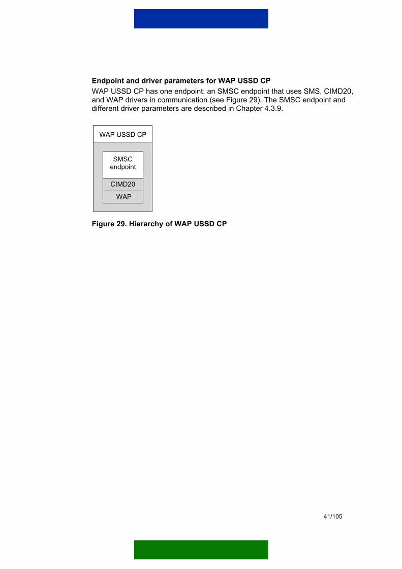
Endpoint and driver parameters for WAP USSD CP WAP USSD CP has one endpoint: an SMSC endpoint that uses SMS, CIMD20, and WAP drivers in communication (see Figure 29). The SMSC endpoint and different driver parameters are described in Chapter 4.3.9.
WAP USSD CP
CIMD20
SMSCendpoint
WAP
Figure 29. Hierarchy of WAP USSD CP
42/105
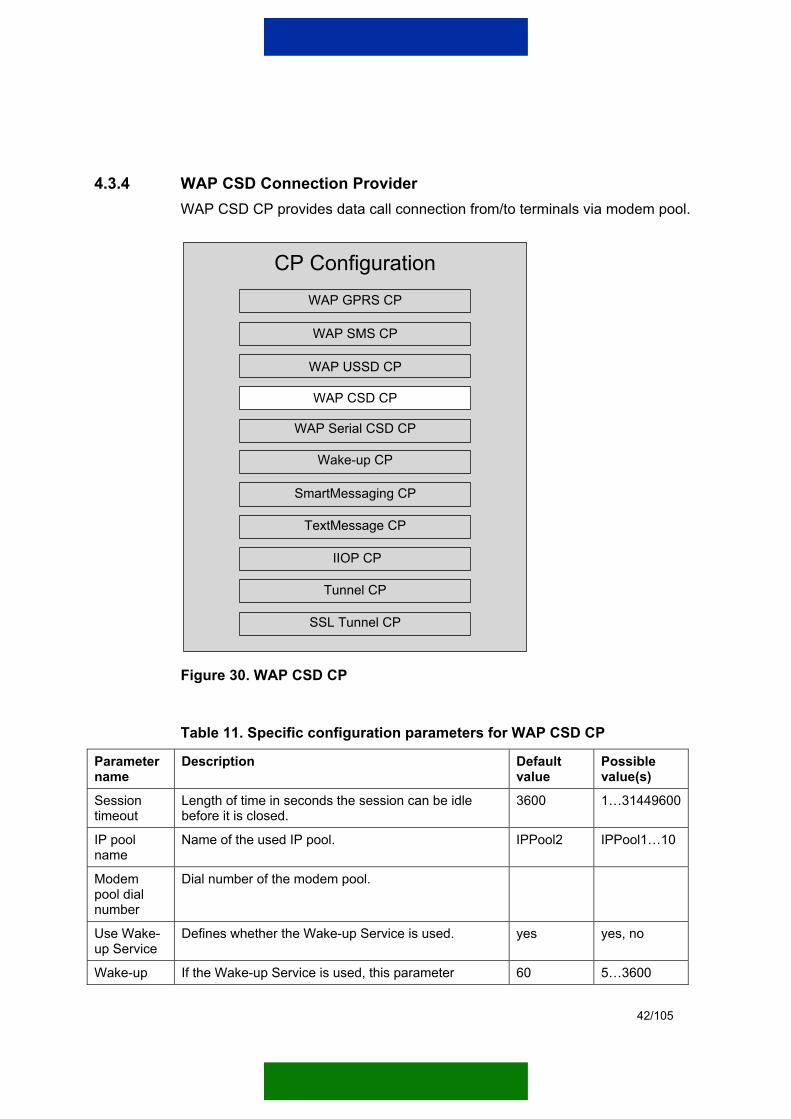
4.3.4 WAP CSD Connection Provider WAP CSD CP provides data call connection from/to terminals via modem pool.
CP ConfigurationWAP GPRS CP
WAP SMS CP
WAP USSD CP
SmartMessaging CP
WAP CSD CP
Wake-up CP
TextMessage CP
Tunnel CP
SSL Tunnel CP
WAP Serial CSD CP
IIOP CP
Figure 30. WAP CSD CP
Table 11. Specific configuration parameters for WAP CSD CP
Parameter name
Description Default value
Possible value(s)
Session timeout
Length of time in seconds the session can be idle before it is closed.
3600 1…31449600
IP pool name
Name of the used IP pool. IPPool2 IPPool1…10
Modem pool dial number
Dial number of the modem pool.
Use Wake-up Service
Defines whether the Wake-up Service is used. yes yes, no
Wake-up ti t
If the Wake-up Service is used, this parameter ifi th l th f ti i d th k
60 5…3600
43/105
Parameter name
Description Default value
Possible value(s)
timeout specifies the length of time in seconds the wake-up may take.
Initial number of threads
Initial number of threads.
Note! Advanced parameter. 6 1…100
Wake-up port
Port where the wake-up messages are sent. The terminal must have a WAP SMS bearer set-up that uses this port.
1 0...65535
Wake-up security time
Defines the length of time in seconds the Wake-up Service waits before it creates a new wake-up after the GPRS context has dropped. This value is used only if the Wake-up Service is enabled.
0 (no timeout used)
0…3600
Wake-up bearer
When the Wake-up Service is used, this parameter sets the used wake-up bearer. This bearer must be one of the Wake-up CPs of the Wake-up Service. Type the name of the Wake-up CP here.
disabled Connection Provider name
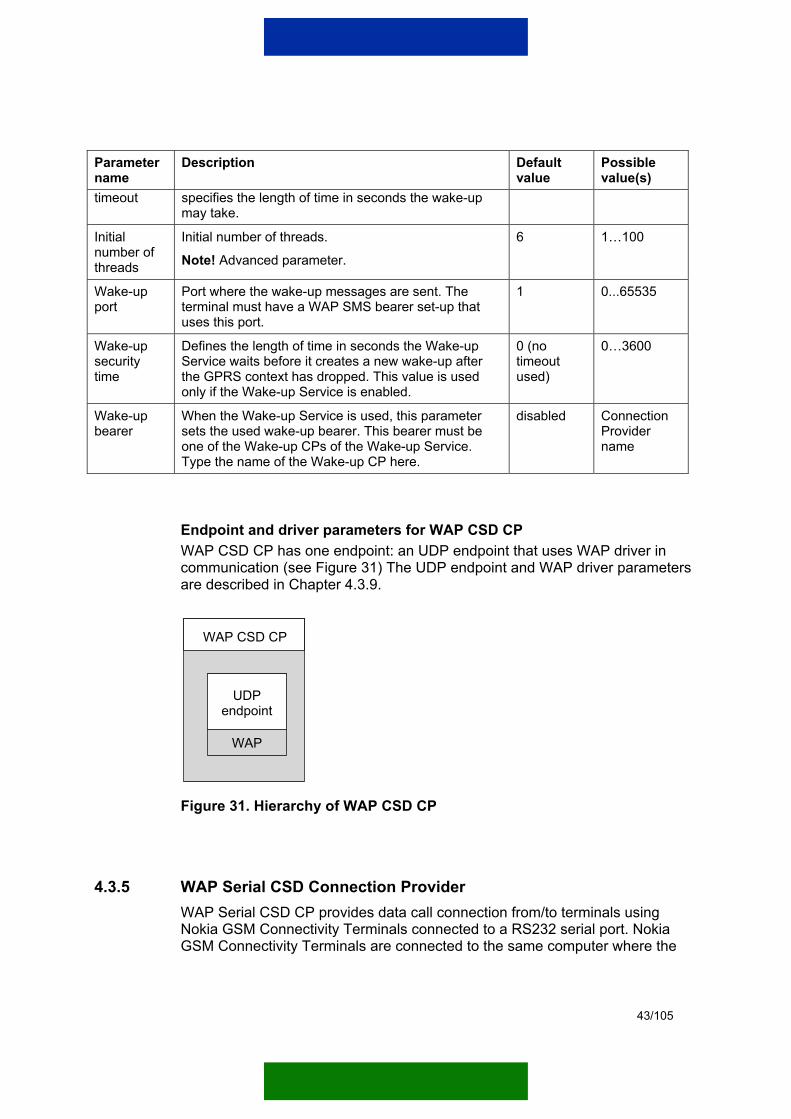
Endpoint and driver parameters for WAP CSD CP WAP CSD CP has one endpoint: an UDP endpoint that uses WAP driver in communication (see Figure 31) The UDP endpoint and WAP driver parameters are described in Chapter 4.3.9.
WAP CSD CP
UDPendpoint
WAP
Figure 31. Hierarchy of WAP CSD CP
4.3.5 WAP Serial CSD Connection Provider WAP Serial CSD CP provides data call connection from/to terminals using Nokia GSM Connectivity Terminals connected to a RS232 serial port. Nokia GSM Connectivity Terminals are connected to the same computer where the

44/105
Gateway is installed. WAP Serial CSD CP has four configurable slots each containing the same parameters.
Note: WAP Serial CSD CP can be used only in Windows operating systems.
Note: When Nokia GSM Connectivity Terminals are used as modems, they should not contain any M2M connection bearers and must be in the AT command mode. For more information, refer to the documentation of the Nokia GSM Connectivity Terminal in question.
CP ConfigurationWAP GPRS CP
WAP SMS CP
WAP USSD CP
SmartMessaging CP
WAP CSD CP
Wake-up CP
TextMessage CP
Tunnel CP
SSL Tunnel CP
WAP Serial CSD CP
IIOP CP
Figure 32. WAP Serial CSD CP
Table 12. Specific configuration parameters for WAP Serial CSD CP
Parameter name
Description Default value
Possible value(s)
Session timeout
Length of time in seconds the session can be idle before it is closed.
3600 1…31449600
45/105
Parameter name
Description Default value
Possible value(s)
IP pool name
Name of the used IP pool. IPPool2 IPPool1…10
Modem pool dial number
Dial number of the modem pool.
Use Wake-up Service
Defines whether the Wake-up Service is used. Yes yes, no
Wake-up timeout
If the Wake-up Service is used, this parameter specifies the length of time in seconds the wake-up may take.
60 5…3600
Initial number of threads
Initial number of threads.
Note! Advanced parameter. 6 1…100
Wake-up port
Port where the wake-up messages are sent. The terminal must have a WAP SMS bearer set-up that uses this port.
1 0...65535
Wake-up security time
Defines the length of time in seconds the Wake-up Service waits before it creates a new wake-up after the GPRS context has dropped. This value is used only if the Wake-up Service is enabled.
0 (no timeout used)
0…3600
Wake-up bearer
When the Wake-up Service is used, this parameter sets the used wake-up bearer. This bearer must be one of the Wake-up CPs of the Wake-up Service. Type the name of the Wake-up CP here.
Disabled Connection Provider name
46/105
Endpoint and driver parameters for WAP Serial CSD CP
WAP Serial CSD CP has one endpoint: a Serial CSD endpoint that uses WAP driver in communication (see Figure 33). The Serial CSD endpoint and WAP driver parameters are described in Chapter 4.3.9.
Serial CSDendpoint
WAP
WAP Serial CSD CP
Figure 33. Hierarchy of WAP Serial CSD CP
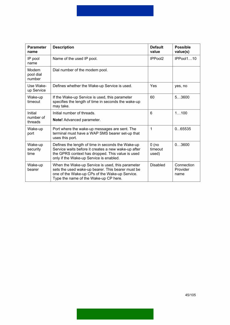
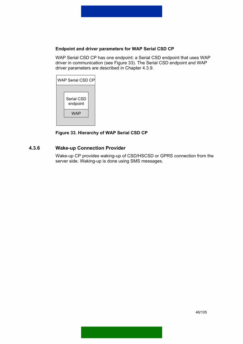
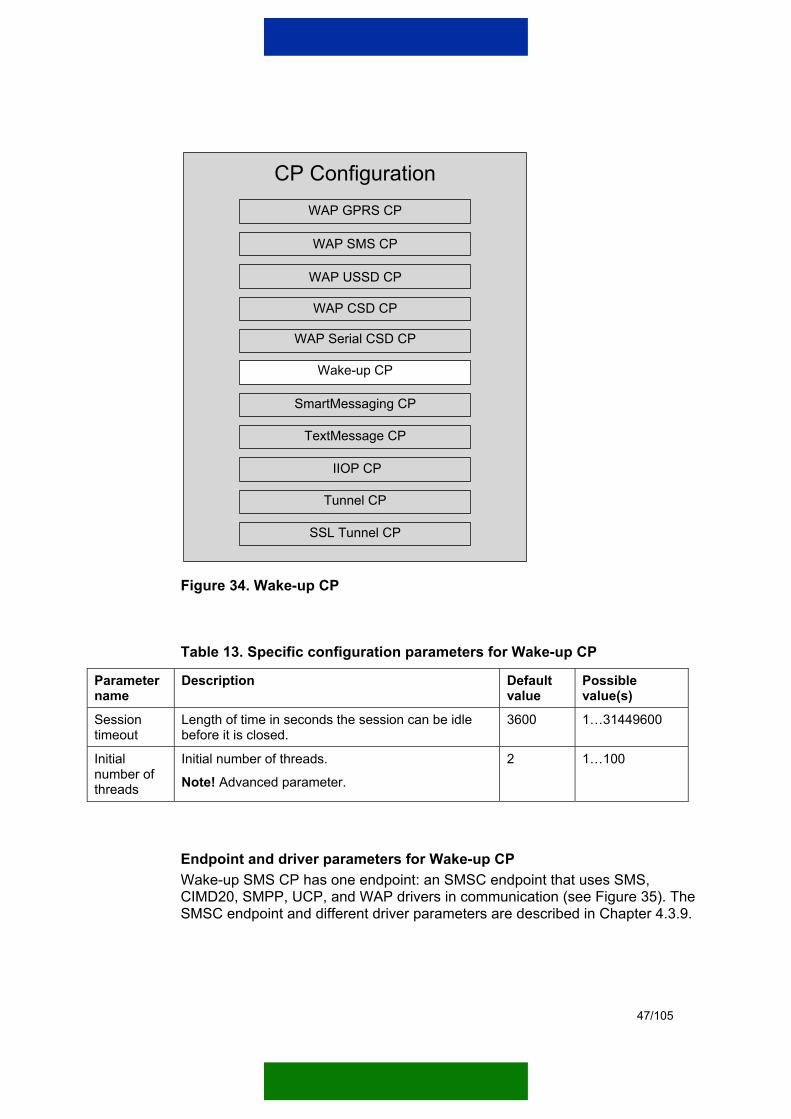
4.3.6 Wake-up Connection Provider Wake-up CP provides waking-up of CSD/HSCSD or GPRS connection from the server side. Waking-up is done using SMS messages.
47/105
CP ConfigurationWAP GPRS CP
WAP SMS CP
WAP USSD CP
SmartMessaging CP
WAP CSD CP
Wake-up CP
TextMessage CP
Tunnel CP
SSL Tunnel CP
WAP Serial CSD CP
IIOP CP
Figure 34. Wake-up CP
Table 13. Specific configuration parameters for Wake-up CP
Parameter name
Description Default value
Possible value(s)
Session timeout
Length of time in seconds the session can be idle before it is closed.
3600 1…31449600
Initial number of threads
Initial number of threads.
Note! Advanced parameter. 2 1…100
Endpoint and driver parameters for Wake-up CP Wake-up SMS CP has one endpoint: an SMSC endpoint that uses SMS, CIMD20, SMPP, UCP, and WAP drivers in communication (see Figure 35). The SMSC endpoint and different driver parameters are described in Chapter 4.3.9.
48/105
Wake-up CP
CIMD20
SMSCendpoint
SMPP
UCP
WAP
Figure 35. Hierarchy of Wake-up CP
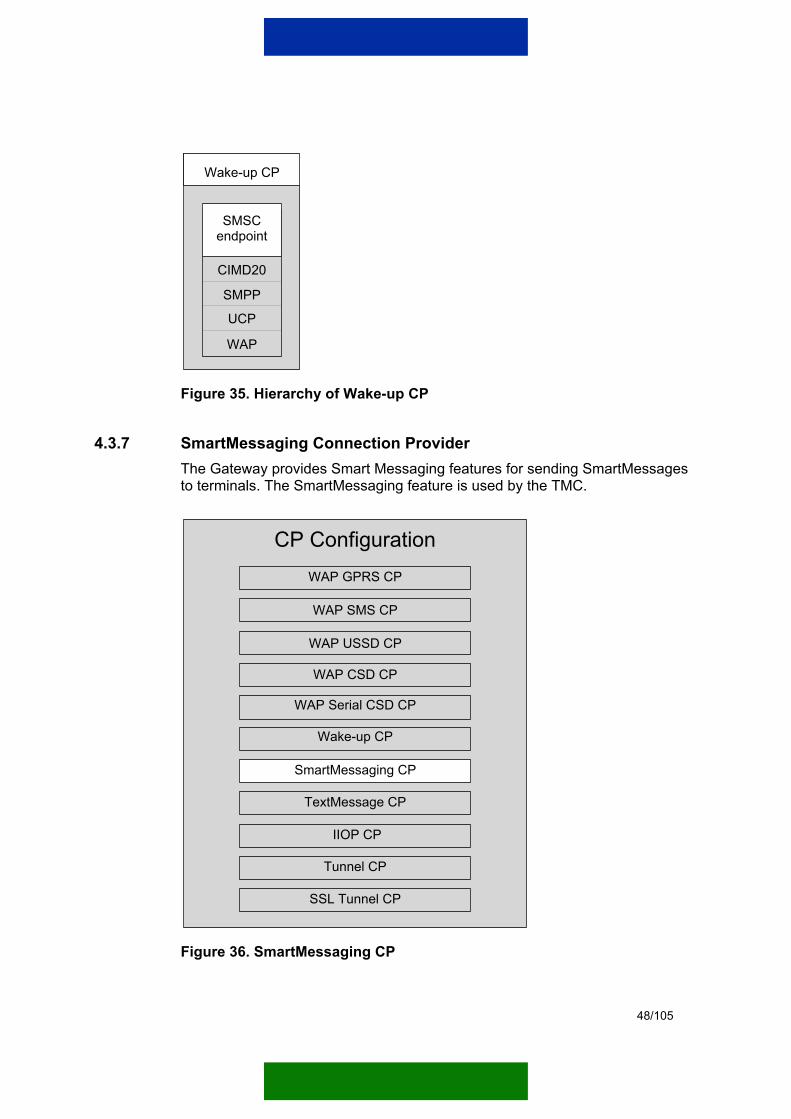
4.3.7 SmartMessaging Connection Provider The Gateway provides Smart Messaging features for sending SmartMessages to terminals. The SmartMessaging feature is used by the TMC.
CP ConfigurationWAP GPRS CP
WAP SMS CP
WAP USSD CP
SmartMessaging CP
WAP CSD CP
Wake-up CP
TextMessage CP
Tunnel CP
SSL Tunnel CP
WAP Serial CSD CP
IIOP CP
Figure 36. SmartMessaging CP

49/105
Table 14. Specific configuration parameters for SmartMessaging CP
Parameter name
Description Default value
Possible value(s)
Session timeout
Length of time in seconds the session can be idle before it is closed.
3600 1…31449600
Local IP address
IP address of the network adapter that listens to upcoming connection requests. With this address, you can point at a selected network card if the computer has more than one network card. If this value is set to 'localhost', the CP binds to the default network interface of the system.
localhost String 'localhost' or valid IP address 0.0.0.0…255.255.255.255
Local port Port number of the CP. 6786 0…65535
Maximum wait queue
Maximum number of pending incoming connections.
50
Initial number of threads
Initial number of threads. 2 1…100
Allowed IP CP allows connections from this IP address. localhost String 'localhost' or valid IP address 0.0.0.0…255.255.255.255
Allowed netmask
Mask that filters the IP address where connections are allowed.
0.0.0.0 Valid IP address 0.0.0.0…255.255.255.255
Endpoint and driver parameters for SmartMessaging CP SmartMessaging CP has one endpoint: an SMSC endpoint that uses SMS, CIMD20, SMPP, UCP, and WAP drivers in communication (see Figure 37). The SMSC endpoint and different driver parameters are described in Chapter 4.3.9.

50/105
SmartMessaging CP
CIMD20
SMSCendpoint
SMPP
UCP
WAP
Figure 37. Hierarchy of SmartMessaging CP
4.3.8 Text Message Connection Provider Text Message CP provides the ability to send text messages from the server side to terminals or to receive text messages and route them to the server application.
Note: The Text Message CP can handle only textual SMS messages.

51/105
CP ConfigurationWAP GPRS CP
WAP SMS CP
WAP USSD CP
SmartMessaging CP
WAP CSD CP
Wake-up CP
Text Message CP
Tunnel CP
SSL Tunnel CP
WAP Serial CSD CP
IIOP CP
Figure 38. Text Message CP
Table 15. Specific configuration parameters for Text Message CP
Parameter name
Description Default value Possible value(s)
Own name in CORBA Naming Service
Name that is used when the CP registers to the CORBA Naming Service.
TextMessageCP string
Target name in CORBA Name Service
Application name of the customer in the CORBA Naming Service.
CustomersApplication string
Session timeout
Length of time in seconds the session can be idle before it is closed.
3600 1…31449600
Gateway IP address
IP address of an active IIOP CP.
localhost String 'localhost' or valid IP address 0.0.0.0…255.255.255.255
Gateway port Port number of an active IIOP CP. One IIOP CP must be
6777 0…65535

52/105
Parameter name
Description Default value Possible value(s)
activated and the Gateway IP address and Gateway port must point to the chosen CP port. This is used when registering to the Naming Service.
Initial number of threads
Initial number of threads. 2 1…100
Authentication of incoming short messages
When this parameter value is set to 'yes', the CP authenticates all incoming messages before delivering them to the server application. When set to 'no', all messages are delivered without authentication. In this case, the server application must perform authentication of the incoming messages. (For increased security, the server application may perform this also when ‘yes’ is selected.)
yes yes, no
Endpoint and driver parameters for Text Message CP Text Message CP has one endpoint: an SMSC endpoint that uses SMS, CIMD20, SMPP, UCP, and WAP drivers in communication (see Figure 39). The SMSC endpoint and different driver parameters are described in Chapter 4.3.9.

53/105
Text Message CP
CIMD20
SMSCendpoint
SMPP
UCP
WAP
Figure 39. Hierarchy of Text Message CP
4.3.9 Endpoint and driver properties This chapter describes the endpoint and driver parameters used by the CPs.
4.3.9.1 UDP endpoint parameters
Table 16. UDP endpoint parameters
Parameter name Description Default value
Possible value(s)
UDP receiver buffer size
Buffer size in bytes for received UDP packets.
Note! Advanced parameter.
4096 512…20000
Local IP address IP address of the network adapter that listens to upcoming connection requests. With this address, you can point at a selected network card if the computer has more than one network card. If this value is set to 'localhost', the CP binds to the default network interface of the system.
localhost String 'localhost' or valid IP address 0.0.0.0…255.255.255.255
Local port Port number of the CP. 9200 0…65535
GPRS access point name
Name of the GPRS access point. This parameter serves the TMC.
Note! Only with GPRS CP.
string
54/105
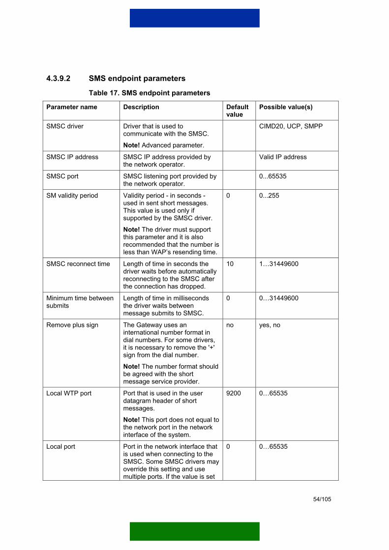
4.3.9.2 SMS endpoint parameters
Table 17. SMS endpoint parameters
Parameter name Description Default value
Possible value(s)
SMSC driver Driver that is used to communicate with the SMSC.
Note! Advanced parameter.
CIMD20, UCP, SMPP
SMSC IP address SMSC IP address provided by the network operator.
Valid IP address
SMSC port SMSC listening port provided by the network operator.
0...65535
SM validity period Validity period - in seconds - used in sent short messages. This value is used only if supported by the SMSC driver.
Note! The driver must support this parameter and it is also recommended that the number is less than WAP’s resending time.
0 0...255
SMSC reconnect time Length of time in seconds the driver waits before automatically reconnecting to the SMSC after the connection has dropped.
10 1…31449600
Minimum time between submits
Length of time in milliseconds the driver waits between message submits to SMSC.
0 0…31449600
Remove plus sign The Gateway uses an international number format in dial numbers. For some drivers, it is necessary to remove the '+' sign from the dial number.
Note! The number format should be agreed with the short message service provider.
no yes, no
Local WTP port Port that is used in the user datagram header of short messages.
Note! This port does not equal to the network port in the network interface of the system.
9200 0…65535
Local port Port in the network interface that is used when connecting to the SMSC. Some SMSC drivers may override this setting and use multiple ports. If the value is set
0 0…65535

55/105
Parameter name Description Default value
Possible value(s)
to '0', a free port provided by the system is used.
CHAR_CONVERSION_ TABLE_7BIT
The used conversion table. default default
Local IP address Network interface to where the endpoint binds.
localhost String 'localhost' or valid IP address 0.0.0.0…255.255.255.255
4.3.9.3 Serial CSD endpoint parameters
Table 18. Serial CSD endpoint parameters
Parameter name Description Default value
Possible value(s)
Slot enabled Defines whether the serial port configured in this slot is in use.
no yes, no
Serial port Serial port to which the terminal is connected. COMx (x = slot number)
COM1…COMn (n = maximum supported serial port count)
Serial port baud rate Baud rate of the serial port. 9600 2400, 4800, 9600, 19200, 38400, 57600, 115200
Serial port data bits Number of data bits used in serial communication.
8 4…8
Serial port parity Parity used in serial communication. none none, even, odd, mark, space
Serial port stop bits Number of stop bits used in serial communication.
1 1, 1.5, 2
Serial port flow control Flow control used in serial communication. none none, xon, xoff, hardware
PPP log enabled Defines whether the PPP log writing option is enabled.
no yes, no
PPP log file directory PPP log file directory where the log file is saved when the PPP log is enabled.
Dial timeout Dial timeout in seconds for establishing a CSD link with a terminal. The link is established when the carrier has been received and the online mode is on.
70 10…300
56/105
Parameter name Description Default value
Possible value(s)
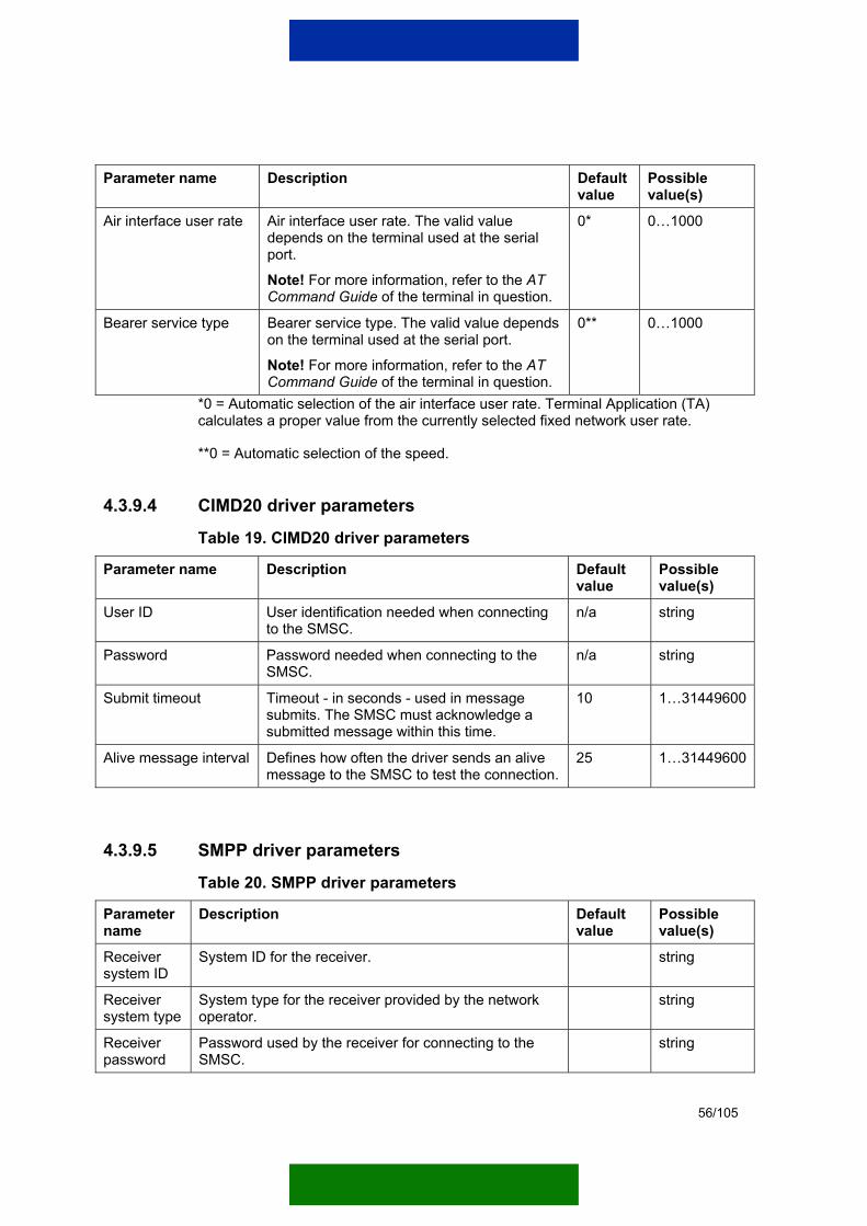
Air interface user rate Air interface user rate. The valid value depends on the terminal used at the serial port.
Note! For more information, refer to the AT Command Guide of the terminal in question.
0* 0…1000
Bearer service type Bearer service type. The valid value depends on the terminal used at the serial port.
Note! For more information, refer to the AT Command Guide of the terminal in question.
0** 0…1000
*0 = Automatic selection of the air interface user rate. Terminal Application (TA) calculates a proper value from the currently selected fixed network user rate.
**0 = Automatic selection of the speed.
4.3.9.4 CIMD20 driver parameters
Table 19. CIMD20 driver parameters
Parameter name Description Default value
Possible value(s)
User ID User identification needed when connecting to the SMSC.
n/a string
Password Password needed when connecting to the SMSC.
n/a string
Submit timeout Timeout - in seconds - used in message submits. The SMSC must acknowledge a submitted message within this time.
10 1…31449600
Alive message interval Defines how often the driver sends an alive message to the SMSC to test the connection.
25 1…31449600
4.3.9.5 SMPP driver parameters
Table 20. SMPP driver parameters
Parameter name
Description Default value
Possible value(s)
Receiver system ID
System ID for the receiver. string
Receiver system type
System type for the receiver provided by the network operator.
string
Receiver password
Password used by the receiver for connecting to the SMSC.
string
57/105
Parameter name
Description Default value
Possible value(s)
Note! Advanced parameter.
Receiver address range
Address range for the receiver provided by the network operator.
Note! Advanced parameter.
string
Receiver address TON
Type of Network for the receiver. 1 0…255
Receiver address NPI
Numbering Plan Identification for the receiver. 1 0…255
Receiver local port
Local port for the receiver. If the value is set to '0', a free port provided by the system is used.
0 0...65535
Receiver SMSC port
The receiver connects to this SMSC port. 0...65535
Transmitter system ID
System ID for the transmitter. string
Transmitter system type
System type for the transmitter provided by the network operator.
string
Transmitter password
Password used by the transmitter for connecting to the SMSC.
string
Transmitter address range
Address range for the transmitter provided by the network operator.
n/a
Transmitter address TON
Type of Network for the transmitter. 1 0…255
Transmitter address NPI
Numbering Plan Identification for the transmitter. 1 0…255
Transmitter local port
Local port for the transmitter. If the value is set to '0', a free port provided by the system is used.
0 0...65535
Transmitter SMSC port
The transmitter connects to this SMSC port. 0...65535
Destination address TON
Type of Network for destination. 1 0…255
Destination address NPI
Numbering Plan Identification for short message destination.
1 0…255
Interface version
Selects the used SMPP protocol version. 3.4 3.3 or 3.4

58/105
Parameter name
Description Default value
Possible value(s)
Ping interval
Defines how often the driver sends an ‘alive’ message to the SMSC to test the connection.
10 1…31449600
SMSC dial number
Dial number for the SMSC. n/a string
Transfer mode
Transfer mode for short messages. SMSC default
SMSC default, Datagram, Store and forward
4.3.9.6 UCP driver parameters
Table 21. UCP driver parameters
Parameter name
Description Default value
Possible value(s)
Delivery host
IP address for the Gateway. localhost String 'localhost' or valid IP address 0.0.0.0…255.255.255.255
Delivery port
Port that the driver listens to for incoming short messages.
4250 0…65535
Use session
Defines whether the driver should use sessions.
Note! Advanced parameter.
no yes, no
SMSC TON
Type of Network for the SMSC.
Note! Advanced parameter.
1 0…255
SMSC NPI Numbering Plan Identification for the SMSC. 1 0…255
SMSC password
Password needed when connecting to the SMSC. Used only if the Use session parameter value is set to 'yes'.
string
4.3.9.7 WAP driver parameters
Table 22. WAP driver parameters
Parameter name
Description Default value
Possible value(s)
WTP retransmission counter
Number of retransmissions made if the responder does not acknowledge the sent invoke.
4 1...100
59/105
Parameter name
Description Default value
Possible value(s)
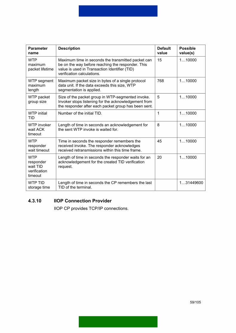
WTP maximum packet lifetime
Maximum time in seconds the transmitted packet can be on the way before reaching the responder. This value is used in Transaction Identifier (TID) verification calculations.
15 1…10000
WTP segment maximum length
Maximum packet size in bytes of a single protocol data unit. If the data exceeds this size, WTP segmentation is applied.
768 1…10000
WTP packet group size
Size of the packet group in WTP-segmented invoke. Invoker stops listening for the acknowledgement from the responder after each packet group has been sent.
5 1…10000
WTP initial TID
Number of the initial TID. 1 1…10000
WTP invoker wait ACK timeout
Length of time in seconds an acknowledgement for the sent WTP invoke is waited for.
8 1…10000
WTP responder wait timeout
Time in seconds the responder remembers the received invoke. The responder acknowledges received retransmissions within this time frame.
45 1…10000
WTP responder wait TID verification timeout
Length of time in seconds the responder waits for an acknowledgement for the created TID verification request.
20 1…10000
WTP TID storage time
Length of time in seconds the CP remembers the last TID of the terminal.
1…31449600
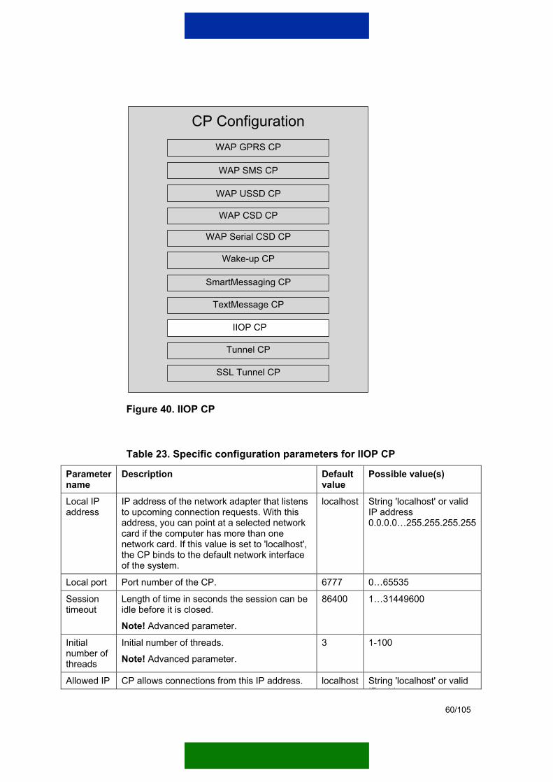
4.3.10 IIOP Connection Provider IIOP CP provides TCP/IP connections.
60/105
CP ConfigurationWAP GPRS CP
WAP SMS CP
WAP USSD CP
SmartMessaging CP
WAP CSD CP
Wake-up CP
TextMessage CP
Tunnel CP
SSL Tunnel CP
WAP Serial CSD CP
IIOP CP
Figure 40. IIOP CP
Table 23. Specific configuration parameters for IIOP CP
Parameter name
Description Default value
Possible value(s)
Local IP address
IP address of the network adapter that listens to upcoming connection requests. With this address, you can point at a selected network card if the computer has more than one network card. If this value is set to 'localhost', the CP binds to the default network interface of the system.
localhost String 'localhost' or valid IP address 0.0.0.0…255.255.255.255
Local port Port number of the CP. 6777 0…65535
Session timeout
Length of time in seconds the session can be idle before it is closed.
Note! Advanced parameter.
86400 1…31449600
Initial number of threads
Initial number of threads.
Note! Advanced parameter. 3 1-100
Allowed IP CP allows connections from this IP address. localhost String 'localhost' or valid IP dd
61/105
Parameter name
Description Default value
Possible value(s)
Note! Advanced parameter. Using ‘Allowed IP’ parameter with IIOP CP improves data security.
IP address 0.0.0.0…255.255.255.255
Allowed netmask
Mask that filters the IP address from where connections are allowed.
Note! Advanced parameter. Using ‘Allowed netmask’ parameter with IIOP CP improves data security.
0.0.0.0 Valid IP address 0.0.0.0…255.255.255.255
Examples of using Allowed IP and Allowed netmask parameters Default setting:
Allowed IP = localhost Allowed netmask = 0.0.0.0
Default setting does not restrict the incoming connections.
Example 1:
Allowed IP = 10.34.1.41 Allowed netmask = 255.255.255.0
CP accepts connections from any given address of the 10.34.1.0 sub network.
Example 2:
Allowed IP = 10.34.1.41 Allowed netmask = 0.0.0.0
CP accepts connections from any given address (the network address is 0.0.0.0).
62/105
Example 3:
Allowed IP = 10.34.1.41 Allowed netmask = 255.255.255.255
CP accepts connections only from the 10.34.1.41 address.
Example 4:
Allowed IP = localhost Allowed netmask = 255.255.255.255
CP accepts connections from the Gateway.
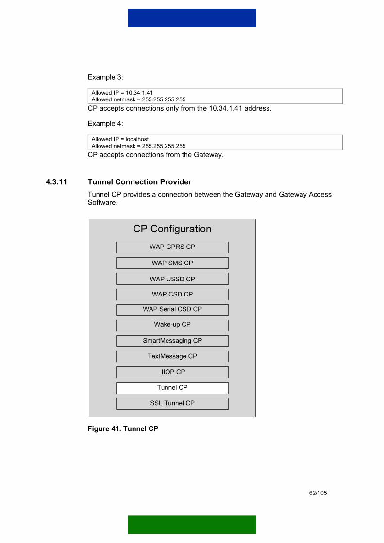
4.3.11 Tunnel Connection Provider Tunnel CP provides a connection between the Gateway and Gateway Access Software.
CP ConfigurationWAP GPRS CP
WAP SMS CP
WAP USSD CP
SmartMessaging CP
WAP CSD CP
Wake-up CP
TextMessage CP
Tunnel CP
SSL Tunnel CP
WAP Serial CSD CP
IIOP CP
Figure 41. Tunnel CP

63/105
Table 24. Specific configuration parameters for Tunnel CP
Parameter name
Description Default value
Possible value(s)
Session timeout
Length of time in seconds the session can be idle before it is closed.
Note! Advanced parameter.
86400 1…31449600
Local IP address
IP address of the network adapter that listens to upcoming connection requests. With this address, you can point at a selected network card if the computer has more than one network card. If this value is set to 'localhost', the CP binds to the default network interface of the system.
localhost String 'localhost' or valid IP address 0.0.0.0…255.255.255.255
Local port Port number of the CP. 6783 1…65535
Initial number of threads
Initial number of threads.
Note! Advanced parameter. 6 0…100
Enable 'keep alive'
Defines whether the Gateway uses 'keep alive' messages to keep the tunnel open.
Note! Advanced parameter.
no yes, no
'Keep alive' time interval
When 'keep alive' is enabled, this parameter defines the time in seconds between two 'keep alive' messages.
Note! Advanced parameter.
120 0…1000
'Keep alive' timeout
When 'keep alive' is enabled, this parameter defines how long a response is waited for a 'keep alive' message before the connection is closed.
Note! Advanced parameter.
10 0…1000
Connection retry wait time
Length of time in seconds after which the CP retries to establish a connection to the target.
Note! Advanced parameter.
10 0…1000
4.3.12 SSL Tunnel Connection Provider SSL Tunnel CP provides increased security to a connection between the Nokia M2M Gateway Service Provider Edition and Gateway Access Software. For more information on SLL, refer to Chapter 5.

64/105
CP ConfigurationWAP GPRS CP
WAP SMS CP
WAP USSD CP
SmartMessaging CP
WAP CSD CP
Wake-up CP
TextMessage CP
Tunnel CP
SSL Tunnel CP
WAP Serial CSD CP
IIOP CP
Figure 42. SSL Tunnel CP
Table 25. Specific configuration parameters for SSL Tunnel CP
Parameter name
Description Default value
Possible value(s)
Session timeout
Length of time in seconds the session can be idle before it is closed.
Note! Advanced parameter.
86400 1…31449600
Local IP address
IP address of the network adapter that listens to upcoming connection requests. With this address, you can point at a selected network card if the computer has more than one network card. If this value is set to 'localhost', the CP binds to the default network interface of the system.
localhost String 'localhost' or valid IP address 0.0.0.0…255.255.255.255
Local port Port number of the CP. 6783 1…65535
Initial number of threads
Initial number of threads.
Note! Advanced parameter. 6 0…100

65/105
Parameter name
Description Default value
Possible value(s)
Enable 'keep alive'
Defines whether the Gateway uses 'keep alive' messages to keep the tunnel open.
Note! Advanced parameter.
no yes, no
'Keep alive' time interval
When 'keep alive' is enabled, this parameter defines the time in seconds between two 'keep alive' messages.
Note! Advanced parameter.
120 0…1000
'Keep alive' timeout
When 'keep alive' is enabled, this parameter defines how long a response is waited for a 'keep alive' message before the connection is closed.
Note! Advanced parameter.
10 0…1000
Connection retry wait time
Length of time in seconds after which the CP retries to establish a connection to the target.
Note! Advanced parameter.
10 0…1000
4.4 IOR HANDLER CONFIGURATION IOR Handlers are used to resolve target addresses for incoming requests. The Gateway has five different IOR Handler types that are described in this chapter.
To use an IOR Handler type, you first need to install, load, and activate it.
Note: It is advisable to load only one IOR Handler instance for one IOR Handler Type, because the first found IOR Handler instance is always used.
When the Gateway is restarted, it proceeds to activate the same IOR Handler instances that where active when the Gateway was shut down.
To remove an IOR Handler type, you need to deactivate, unload, and uninstall it.
Table 26. IOR Handler types
IOR Handler type Description
IIOP IOR Handler Resolves the network address for IIOP connection from the IIOP profile. The IIOP profile contains the following information: • Version
• Host
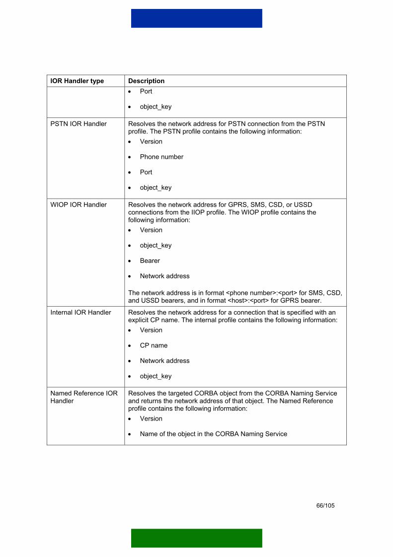
66/105
IOR Handler type Description • Port
• object_key
PSTN IOR Handler Resolves the network address for PSTN connection from the PSTN profile. The PSTN profile contains the following information: • Version
• Phone number
• Port
• object_key
WIOP IOR Handler Resolves the network address for GPRS, SMS, CSD, or USSD connections from the IIOP profile. The WIOP profile contains the following information: • Version
• object_key
• Bearer
• Network address
The network address is in format <phone number>:<port> for SMS, CSD, and USSD bearers, and in format <host>:<port> for GPRS bearer.
Internal IOR Handler Resolves the network address for a connection that is specified with an explicit CP name. The internal profile contains the following information: • Version
• CP name
• Network address
• object_key
Named Reference IOR Handler
Resolves the targeted CORBA object from the CORBA Naming Service and returns the network address of that object. The Named Reference profile contains the following information: • Version
• Name of the object in the CORBA Naming Service

67/105
4.5 DOMAIN CONFIGURATION The main function of a domain is to define which CPs are used to communicate with terminals and which tunnel connections are used to communicate with the Gateway Access Software. These connections may be duplicated to improve redundancy. In that case, the Gateway switches to a second CP if communication fails with the first one.
To use a domain, the administrator first needs to create, configure, and activate it.
The following information must be delivered to the Gateway Access Software administrator for the Gateway Access Software to be able to contact the service provider:
• IP and port numbers of the service provider
• Created credentials (if SSL is used)
• Parameter list used when configuring terminals
Table 27. Specific configuration parameters for a given domain
Parameter name
Description Default value
Possible value(s)
Modifier Name of the person who was the last to modify the domain.
Not to be left empty
Cache time for RADIUS information
Length of time in seconds the Gateway caches authentication information of a device.
60 0…2147483647
Additional information
Additional information for the domain.
Additional information
Additional information for the domain.
Idle timeout for GPRS
Length of idle time in seconds before the GSM network closes the context.
86400 0…2147483647
Session timeout for GPRS
Length of time in seconds the GSM network keeps the GPRS context open. When this time is set to ‘0’ (zero), the feature is not used.
0 0…2147483647
Domain activation on Gateway start-up
Defines whether the domain should be activated automatically during Gateway start-up.
yes yes, no
WAP port Specifies the WAP port reserved for the domain i SMS/USSD i ti
0 1…65535

68/105
Parameter name
Description Default value
Possible value(s)
in SMS/USSD communication.
Table 28. Tunnel connection parameters for a give domain
Parameter name
Description Default value
Possible value(s)
Tunnel port The Gateway Access Software of the domain listens to this port.
0 1…65535
CP name Instance name of the Tunnel CP that communicates with the domain.
disabled Not to be left empty
Passive mode
Tunnel opening possible only from the Gateway Access Software.
no yes, no
IP address IP address of the Gateway Access Software of the domain.
change this In format xxx.xxx.xxx.xxx
Table 29. Alternative tunnel connection parameters for a given domain
Parameter name
Description Default value
Possible value(s)
Tunnel port The Gateway Access Software of the domain listens to this port.
0 1…65535
CP name Instance name of the Tunnel CP that communicates with the domain.
disabled Not to be left empty
Passive mode
Tunnel opening possible only from the Gateway Access Software.
no yes, no
IP address IP address of the Gateway Access Software of the domain.
change this In format xxx.xxx.xxx.xxx
Table 30. CP parameters for a given domain
Parameter name
Description Default value
Possible value(s)
IIOP CP name
Name of the IIOP CP. disabled Not to be left empty
Alternative IIOP CP name
Name of the alternative IIOP CP. disabled Not to be left empty
SMS CP name
Name of the SMS CP. disabled Not to be left empty

69/105
Parameter name
Description Default value
Possible value(s)
Alternative SMS CP name
Name of the alternative SMS CP. disabled Not to be left empty
CSD CP name
Name of the CSD CP. disabled Not to be left empty
Alternative CSD CP name
Name of the alternative CSD CP. disabled Not to be left empty
USSD CP name
Name of the USSD CP. disabled Not to be left empty
Alternative USSD CP name
Name of the alternative USSD CP. disabled Not to be left empty
GPRS CP name
Name of the GPRS CP. disabled Not to be left empty
Alternative GPRS CP name
Name of the alternative GPRS CP. disabled Not to be left empty
Smart Messaging CP name
Name of the Smart Messaging CP. disabled Not to be left empty
Alternative Smart Messaging CP name
Name of the alternative Smart Messaging CP. disabled Not to be left empty
SMS Text Message CP name
Name of the SMS Text Message CP. disabled Not to be left empty
Alternative SMS Text Message CP name
Name of the alternative SMS Text Message CP.
disabled Not to be left empty
Table 31. Billing parameters for a given domain
Parameter name
Description Default value
Possible value(s)
Use default billing settings
Defines whether the settings of the general billing configuration should be used.
no yes, no
Generate Session St t t
Defines whether the Gateway should generate billing events of session starts.
yes yes, no
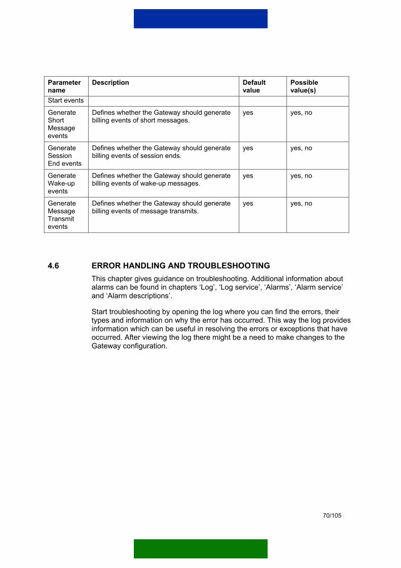
70/105
Parameter name
Description Default value
Possible value(s)
Start events
Generate Short Message events
Defines whether the Gateway should generate billing events of short messages.
yes yes, no
Generate Session End events
Defines whether the Gateway should generate billing events of session ends.
yes yes, no
Generate Wake-up events
Defines whether the Gateway should generate billing events of wake-up messages.
yes yes, no
Generate Message Transmit events
Defines whether the Gateway should generate billing events of message transmits.
yes yes, no
4.6 ERROR HANDLING AND TROUBLESHOOTING This chapter gives guidance on troubleshooting. Additional information about alarms can be found in chapters ‘Log’, ‘Log service’, ‘Alarms’, ‘Alarm service’ and ‘Alarm descriptions’.
Start troubleshooting by opening the log where you can find the errors, their types and information on why the error has occurred. This way the log provides information which can be useful in resolving the errors or exceptions that have occurred. After viewing the log there might be a need to make changes to the Gateway configuration.
71/105
5. SSL TUNNELLING
SSL tunnelling is supported only in communications between the Gateway and Gateway Access Software. It is not possible to use SSL in communication with terminals, server applications or other gateway types.
Note: SSL tunnelling is supported only in the encryption-enabled versions of the Nokia M2M Gateway Service Provider Edition and Gateway Access Software.
The SSL Tunnel CP is installed similarly to other CPs (see Chapter 3.3), and it can function together with IIOP tunnelling. However, the same Gateway Access Software CPs cannot have both SSL tunnelling and IIOP tunnelling enabled. This limitation exists because with IIOP tunnelling the tunnels are identified by IP addresses. Having many domains with the same IP address may create confusion and domain lookup failures.
It is not advisable to use both SSL tunnelling and IIOP tunnelling together with the Gateway Access Software or, at minimum, IIOP tunnelling should be done over hardware VPN.
Note: For more information on SSL tunnelling and SSL credentials, please refer to the Nokia M2M Gateway Gateway Access Software 2.2 Administration Manual.

72/105
6. GATEWAY SERVICES
6.1 INTRODUCTION
Tools and services The browser-based administration tool (Management UI) allows users and administrators to use the Gateway locally or remotely. The functions of the Management UI were explained in Chapter 3.
The Gateway offers the following services:
• Authentication and access control
• Statistics service
• Alarm service
• Log service
• Billing service
Core
Alarm service
Statistics service
Authentication and access control
Log service
Billing service
Figure 43. Tools and services offered by the Gateway

73/105
6.2 AUTHENTICATION AND ACCESS CONTROL
There is an authentication mechanism that uses the RADIUS authentication or the Mobile Subscriber International ISDN Number (MSISDN) checking depending on the used bearer.
In the Gateway, RADIUS authentication is forwarded to the corresponding domain. The Gateway Access Software provides a CORBA interface that is used in forwarding the RADIUS authentication. The same interface is also used when the Gateway asks whether a terminal with a given phone number can access the domain.
6.3 STATISTICS SERVICE The Gateway enables the collection of traffic statistics. This function can be accessed via the Management UI. The user can select the modules where statistics is to be collected from by period and format of statistical information. Java Database Connectivity (JDBC) is supported to help save the collected information in a database.
For more information on collecting statistics, see Chapter 3.8 and the Statistics descriptions in the APPENDIX.
6.4 ALARM SERVICE Whether the alarm service is switched on at start-up or not depends on the alarm service parameter settings. The alarm service parameters can be modified in the gateway.properties file located in the lib directory of the Gateway.
Table 32. Alarm service parameters
Parameter name Description Default value
Possible value(s)
com.nokia.m2m.alarms.disable Enabling or disabling of the alarm service.
yes yes, no
com.nokia.m2m.alarms.useEventService Enabling or disabling the use of Event Service for alarms.
no yes, no
The Gateway alarms are described in more detail in Alarm descriptions in the APPENDIX.

74/105
6.5 LOG SERVICE The Gateway provides a log service for special events. Files are used as the standard output storage method. Database storage is supported by JDBC-enabled databases. The log service parameters can be found in the gateway.properties file located in the bin directory of the Gateway.
The log service is not on as default. If necessary, activate the log service from the gateway.properties file (only with VisiBroker).
Table 33. Log service parameters
Parameter name Description Default value Possible value(s)
com.nokia.m2m.log.localstream.logFile
Name and path of the log file. ../log/gateway.log
com.nokia.m2m.log.localstream.maxSize
Maximum size of the log file in bytes.
100M 100K, 100M, 100T
com.nokia.m2m.log.localstream.keepOld
Defines whether to keep the old log file when the log has received its maximum size. The old log file will be renamed as <logname>.old.
yes, no
com.nokia.m2m.log.localstream.lineWidth
Maximum number of characters on a line in a log file.
80
com.nokia.m2m.log.useEventService
Enabling or disabling the use of Event Service for log.
no yes, no
com.nokia.m2m.log.applicationName
Application name. Nokia M2M Gateway
#com.nokia.m2m.log.defaultLogWriter*
Defines whether the log file is written into the Event Service instead of the directory.
com.nokia.m2m.log.eventservice.EventServiceEntryWriter
#com.nokia.m2m.log.eventservice.backupFile*
Name and path of the log file if it is written into a back-up file in addition to the Event Service.
../log/gateway.log
#com.nokia.m2m.log.eventservice.backupFile*
Back-up level used if the log file is written into a back-up file.
3 0…5
*This parameter is inactivated with the # symbol. The parameter can be taken into use by removing the # symbol only when the use of Event Service for log has been enabled.
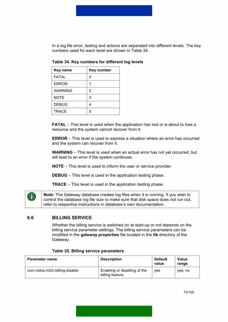
75/105
In a log file error, testing and actions are separated into different levels. The key numbers used for each level are shown in Table 34.
Table 34. Key numbers for different log levels
Key name Key number
FATAL 0
ERROR 1
WARNING 2
NOTE 3
DEBUG 4
TRACE 5
FATAL – This level is used when the application has lost or is about to lose a resource and the system cannot recover from it.
ERROR – This level is used to express a situation where an error has occurred and the system can recover from it.
WARNING – This level is used when an actual error has not yet occurred, but will lead to an error if the system continues.
NOTE – This level is used to inform the user or service provider.
DEBUG – This level is used in the application testing phase.
TRACE – This level is used in the application testing phase.
Note: The Gateway database creates log files when it is running. If you wish to control the database log file size to make sure that disk space does not run out, refer to respective instructions in database’s own documentation.
6.6 BILLING SERVICE Whether the billing service is switched on at start-up or not depends on the billing service parameter settings. The billing service parameters can be modified in the gateway.properties file located in the lib directory of the Gateway.
Table 35. Billing service parameters
Parameter name Description Default value
Value range
com.nokia.m2m.billing.disable Enabling or disabling of the billing feature.
yes yes, no
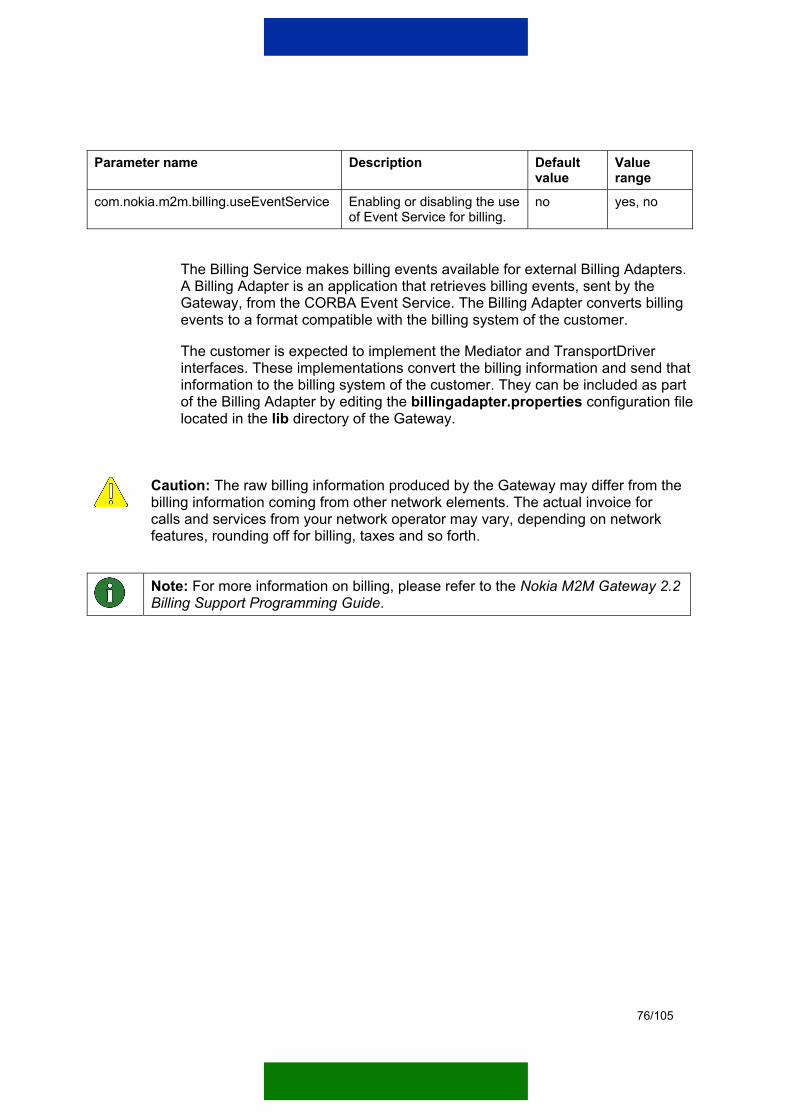
76/105
Parameter name Description Default value
Value range
com.nokia.m2m.billing.useEventService Enabling or disabling the use of Event Service for billing.
no yes, no
The Billing Service makes billing events available for external Billing Adapters. A Billing Adapter is an application that retrieves billing events, sent by the Gateway, from the CORBA Event Service. The Billing Adapter converts billing events to a format compatible with the billing system of the customer.
The customer is expected to implement the Mediator and TransportDriver interfaces. These implementations convert the billing information and send that information to the billing system of the customer. They can be included as part of the Billing Adapter by editing the billingadapter.properties configuration file located in the lib directory of the Gateway.
Caution: The raw billing information produced by the Gateway may differ from the billing information coming from other network elements. The actual invoice for calls and services from your network operator may vary, depending on network features, rounding off for billing, taxes and so forth.
Note: For more information on billing, please refer to the Nokia M2M Gateway 2.2 Billing Support Programming Guide.
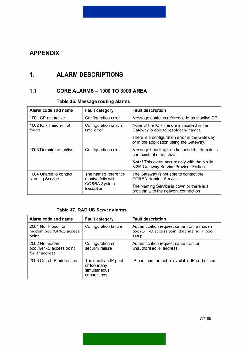
77/105
APPENDIX
1. ALARM DESCRIPTIONS
1.1 CORE ALARMS – 1000 TO 3000 AREA
Table 36. Message routing alarms
Alarm code and name Fault category Fault description
1001 CP not active Configuration error Message contains reference to an inactive CP.
1002 IOR Handler not found
Configuration or run time error
None of the IOR Handlers installed in the Gateway is able to resolve the target.
There is a configuration error in the Gateway or in the application using the Gateway.
1003 Domain not active Configuration error Message handling fails because the domain is non-existent or inactive.
Note! This alarm occurs only with the Nokia M2M Gateway Service Provider Edition.
1004 Unable to contact Naming Service
The named reference resolve fails with CORBA System Exception
The Gateway is not able to contact the CORBA Naming Service.
The Naming Service is down or there is a problem with the network connection
Table 37. RADIUS Server alarms
Alarm code and name Fault category Fault description
2001 No IP pool for modem pool/GPRS access point
Configuration failure Authentication request came from a modem pool/GPRS access point that has no IP pool setup.
2002 No modem pool/GPRS access point for IP address
Configuration or security failure
Authentication request came from an unauthorised IP address.
2003 Out of IP addresses Too small an IP pool or too many simultaneous connections
IP pool has run out of available IP addresses.
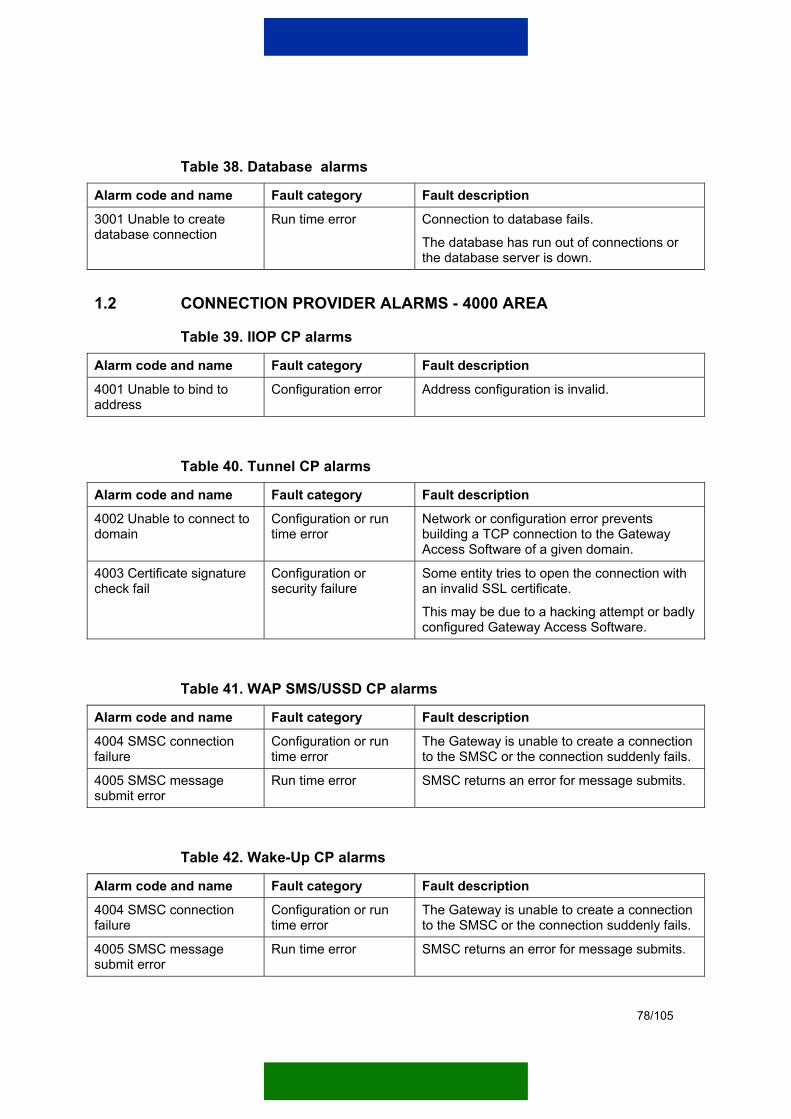
78/105
Table 38. Database alarms
Alarm code and name Fault category Fault description
3001 Unable to create database connection
Run time error Connection to database fails.
The database has run out of connections or the database server is down.
1.2 CONNECTION PROVIDER ALARMS - 4000 AREA
Table 39. IIOP CP alarms
Alarm code and name Fault category Fault description
4001 Unable to bind to address
Configuration error Address configuration is invalid.
Table 40. Tunnel CP alarms
Alarm code and name Fault category Fault description
4002 Unable to connect to domain
Configuration or run time error
Network or configuration error prevents building a TCP connection to the Gateway Access Software of a given domain.
4003 Certificate signature check fail
Configuration or security failure
Some entity tries to open the connection with an invalid SSL certificate.
This may be due to a hacking attempt or badly configured Gateway Access Software.
Table 41. WAP SMS/USSD CP alarms
Alarm code and name Fault category Fault description
4004 SMSC connection failure
Configuration or run time error
The Gateway is unable to create a connection to the SMSC or the connection suddenly fails.
4005 SMSC message submit error
Run time error SMSC returns an error for message submits.
Table 42. Wake-Up CP alarms
Alarm code and name Fault category Fault description
4004 SMSC connection failure
Configuration or run time error
The Gateway is unable to create a connection to the SMSC or the connection suddenly fails.
4005 SMSC message submit error
Run time error SMSC returns an error for message submits.

79/105
Table 43. SmartMessaging CP alarms
Alarm code and name Fault category Fault description
4004 SMSC connection failure
Configuration or run time error
The Gateway is unable to create a connection to the SMSC or the connection suddenly fails.
4005 SMSC message submit error
Run time error SMSC returns an error for message submits.
Table 44. Text Message CP alarms
Alarm code and name Fault category Fault description
4004 SMSC connection failure
Configuration or run time error
The Gateway is unable to create a connection to the SMSC or the connection suddenly fails.
4005 SMSC message submit error
Run time error SMSC returns an error for message submits.
4006 SM submit to application fails
Configuration or run time error
Short message submit to application fails with CORBA System Exception.
A configuration or network problem prevents the Gateway from communicating with the SMS receiver application.
1.3 BILLING ALARMS – 5000 AREA
Table 45. Billing alarms
Alarm code and name Fault category Fault description
5001 Event Channel connection failure
Run time error Connection to the billing channel fails.
Billing record storage is redirected to backup files.
5002 Billing backup fails Run time error Billing backup storage fails. The Gateway is unable to write billing records into XML files.
2. STATISTICS DESCRIPTIONS
2.1 COMMON CONNECTION PROVIDER STATISTICS
Table 46. Common statistics for all CPs
Value Type Description
outgoingMessageCount Cumulative, long Number of successfully sent messages.

80/105
Value Type Description
incomingMessageCount Cumulative, long Number of received messages.
outgoingMessageBytes Cumulative, long Number of sent GIOP data bytes excluding the protocol data.
incomingMessageBytes Cumulative, long Number of received GIOP data bytes excluding the protocol data.
outgoingFailedMessages Cumulative, long Number of failed message transmits.
2.2 SPECIFIC CONNECTION PROVIDER STATISTICS
Table 47. IIOP CP statistics
Value Type Description
outgoingConnections Cumulative, long Number of successfully opened TCP/IP sockets.
incomingConnections Cumulative, long Number of received TCP/IP connections.
outgoingFailedConnections Cumulative, long Number of failed TCP/IP connection attempts.
Table 48. Tunnel CP statistics
Value Type Description
outgoingConnections Cumulative, long Number of successfully opened SSL or TCP/IP sockets.
incomingConnections Cumulative, long Number of received SSL or TCP/IP connections.
outgoingFailedConnections Cumulative, long Number of failed SSL or TCP/IP connection attempts.
Table 49. WAP GPRS CP statistics
Value Type Description
wakeUpMessages Cumulative, long Number of sent wake-up messages.
outgoingBytes Cumulative, long Number of sent bytes.
incomingBytes Cumulative, long Number of received bytes.
Table 50. WAP CSD CP statistics
Value Type Description

81/105
wakeUpMessages Cumulative, long Number of sent wake-up messages.
outgoingBytes Cumulative, long Number of sent bytes.
incomingBytes Cumulative, long Number of received bytes.
Table 51. WAP SMS CP statistics
Value Type Description
outgoingShortMessages Cumulative, long Number of sent short messages.
incomingShortMessages Cumulative, long Number of received short messages.
outgoingBytes Cumulative, long Number of sent bytes.
incomingBytes Cumulative, long Number of received bytes.
Table 52. WAP USSD CP statistics
Value Type Description
outgoingShortMessages Cumulative, long Number of sent short messages.
incomingShortMessages Cumulative, long Number of received short messages.
outgoingBytes Cumulative, long Number of sent bytes.
incomingBytes Cumulative, long Number of received bytes.
Table 53. Text Message CP statistics
Value Type Description
outgoingShortMessages Cumulative, long Number of sent short messages.
incomingShortMessages Cumulative, long Number of received short messages.
outgoingBytes Cumulative, long Number of sent bytes.
incomingBytes Cumulative, long Number of received bytes.
Table 54. SmartMessaging CP
Value Type Description
outgoingShortMessages Cumulative, long Number of sent short messages.
outgoingBytes Cumulative, long Number of sent bytes.
82/105
3. REDUNDANT SERVICE PROVIDING To avoid situations where message transfer fails due to problems in a CP of the Gateway, it is possible to duplicate the CPs of a domain. For example, there may be two WAP CSD CPs using different modem pools. If the first WAP CSD CP fails to send a message, the next message will be send using the other WAP CSD CP. However, the Gateway does not attempt to resend the first message using the second connection, because it has no way of knowing if the first message actually reached the target and only the reply was lost. The application can decide to resend the message when it does not go through.
It is also possible to duplicate the tunnel connection between the Gateway and the Gateway Access Software. This way, the service provider can maintain two different Gateways providing services to the same domain. In this case, both Gateways must have the same SSL root certificate and the Gateway Access Software is configured to communicate with both Gateways.
4. PARAMETERS AND EXAMPLE CONFIGURATION
4.1 PARAMETERS
General parameters The WAP parameters of Nokia GSM Connectivity Terminals are described in Table 55.
Table 55. General WAP parameters of Nokia GSM Connectivity Terminals
Parameter Description
Index Automatically set connection number.
Bearer Connection bearer:
0 = SMS
1 = CSD
2 = USSD
3 = GPRS
(255: deletes the connection parameters)
Connection timeout Length of time before the connection is automatically closed (0: not used).
32-bit value must be given in two 16-bit values. The upper word is usually zero.
WTP port Port number in the Nokia GSM Connectivity Terminal (must be unique to a terminal).
Parameters of the Gateway Access Software.
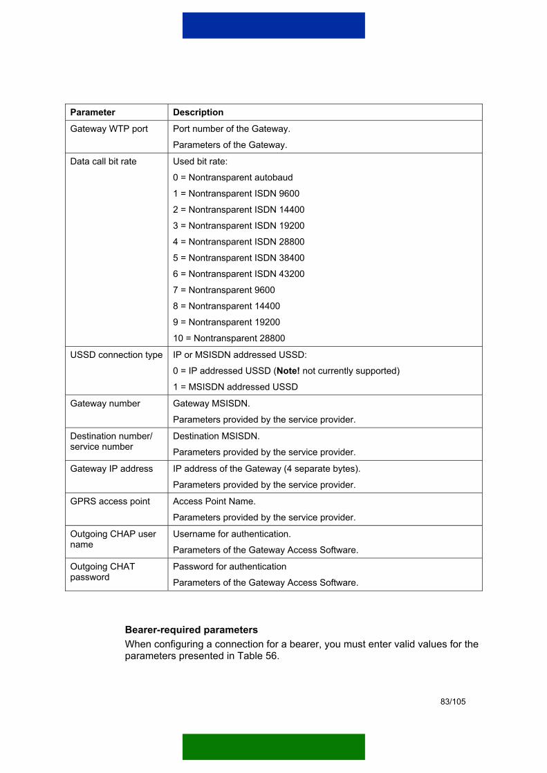
83/105
Parameter Description
Gateway WTP port Port number of the Gateway.
Parameters of the Gateway.
Data call bit rate Used bit rate:
0 = Nontransparent autobaud
1 = Nontransparent ISDN 9600
2 = Nontransparent ISDN 14400
3 = Nontransparent ISDN 19200
4 = Nontransparent ISDN 28800
5 = Nontransparent ISDN 38400
6 = Nontransparent ISDN 43200
7 = Nontransparent 9600
8 = Nontransparent 14400
9 = Nontransparent 19200
10 = Nontransparent 28800
USSD connection type IP or MSISDN addressed USSD:
0 = IP addressed USSD (Note! not currently supported)
1 = MSISDN addressed USSD
Gateway number Gateway MSISDN.
Parameters provided by the service provider.
Destination number/ service number
Destination MSISDN.
Parameters provided by the service provider.
Gateway IP address IP address of the Gateway (4 separate bytes).
Parameters provided by the service provider.
GPRS access point Access Point Name.
Parameters provided by the service provider.
Outgoing CHAP user name
Username for authentication.
Parameters of the Gateway Access Software.
Outgoing CHAT password
Password for authentication
Parameters of the Gateway Access Software.
Bearer-required parameters When configuring a connection for a bearer, you must enter valid values for the parameters presented in Table 56.

84/105
Table 56. Bearer-required parameters
Bearer Required parameters
SMS Wireless bearer (0 = SMS)
WTP port
Gateway WTP port
Destination address
CSD Wireless bearer (1 = CSD)
Connection timeout
WTP port
Gateway WTP port
Data call bit rate (0 … 11)
Gateway number
Gateway IP address
Outgoing CHAP user name
Outgoing CHAP password
USSD – IP
(Note! not currently supported)
Wireless bearer (2 = USSD
WTP port
Gateway WTP port
Connection type (0 = IP addressed USSD)
Service code
Gateway IP address
USSD – MSISDN Wireless bearer (2 = USSD)
WTP port
Gateway WTP port
Connection type (1 = MSISDN addressed USSD)
Service code
Service number
GPRS Wireless bearer (3 = GPRS)
Connection timeout
WTP port
Gateway WTP port
Gateway IP address
GPRS access point
Outgoing CHAP user name
Outgoing CHAP password
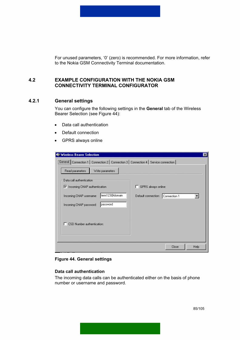
85/105
For unused parameters, ‘0’ (zero) is recommended. For more information, refer to the Nokia GSM Connectivity Terminal documentation.
4.2 EXAMPLE CONFIGURATION WITH THE NOKIA GSM CONNECTIVITY TERMINAL CONFIGURATOR
4.2.1 General settings You can configure the following settings in the General tab of the Wireless Bearer Selection (see Figure 44):
• Data call authentication
• Default connection • GPRS always online
Figure 44. General settings
Data call authentication The incoming data calls can be authenticated either on the basis of phone number or username and password.

86/105
When Data call authentication is based on phone number (CSD Number authentication selected), the Nokia GSM Connectivity Terminal authenticates all incoming data calls and checks the calling phone number. It compares the calling phone number to the Gateway number specified in the Connection tab where CSD settings are located. See Chapter 4.2.2.2.[The phone number identification is probably dependent on the network support and that the numbers are actually given?]
Note: MSISDN based identification requires that the caller MSISDN is provided by the network.
Incoming CHAP username and password The Incoming CHAP username should be the same as the localUserName in the DIS of the Gateway Access Software. The Incoming CHAP password should be the same as the remotePassword in the DIS of the Gateway Access Software.
The Nokia GSM Connectivity Terminal uses the Incoming CHAP username and password to authenticate CSD or GPRS connections coming from the Gateway.
GPRS always online When the GPRS always online box is ticked, the Nokia GSM Connectivity Terminal regenerates a GPRS attach if it is dropped. This allows shorter initialisation times and faster receiving of bursty data.
Default connection Default connection for the application module can be selected from a list of connections. The following connections are possible:
• Connection 1
• Connection 2
• Connection 3
• Connection 4
• Service connection
• Dynamic 6
• Dynamic 7
• Dynamic 8
• Dynamic 9
• Dynamic 10
87/105
Default connection is used whenever the application module attached to the Nokia GSM Connectivity Terminal wants to send data over the network to the server application. It can be changed to another connection at any time either from the server application or by using the application module. This way, the wireless bearer used can be easily changed, for example from HSCSD to GPRS, because the settings for different bearers are defined in different connection tabs.
Connection settings can be defined in the respective Connection tab. For more information see Chapter 4.2.2.
4.2.2 Settings for wireless bearers A connection is set up for each wireless bearer that will be used for communication between the Nokia GSM Connectivity Terminal and the Gateway. For example, if you want to use GPRS and occasionally SMS, you can set GPRS as Connection 1 and SMS as Connection 2. With the Nokia GSM Connectivity Terminal Configurator, you can set up a maximum of five connections for communication. Additional five connections can be set up dynamically via the Nokia M2M Platform.
You can select the following bearers:
• No bearer
• HSCSD/CSD
• SMS
• GPRS
• USSD
Note: The use of these bearers requires network support. For further information and availability contact your service provider.
4.2.2.1 No bearer This is the default state for connections and the starting point for the configuration. The excess connections that are not currently used for communication can be set to No bearer.
Note: The Nokia GSM Connectivity Terminal can only receive configuration via SmartMessaging when all the connections are set to No bearer.
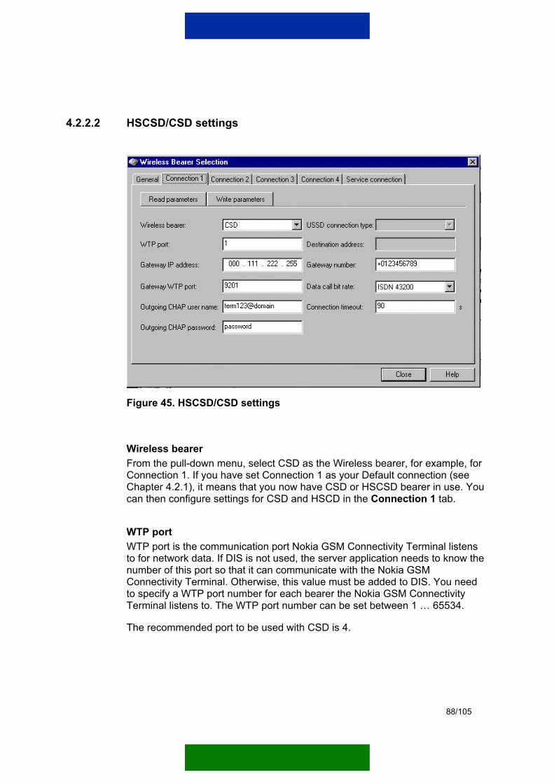
88/105
4.2.2.2 HSCSD/CSD settings
Figure 45. HSCSD/CSD settings
Wireless bearer From the pull-down menu, select CSD as the Wireless bearer, for example, for Connection 1. If you have set Connection 1 as your Default connection (see Chapter 4.2.1), it means that you now have CSD or HSCSD bearer in use. You can then configure settings for CSD and HSCD in the Connection 1 tab.
WTP port WTP port is the communication port Nokia GSM Connectivity Terminal listens to for network data. If DIS is not used, the server application needs to know the number of this port so that it can communicate with the Nokia GSM Connectivity Terminal. Otherwise, this value must be added to DIS. You need to specify a WTP port number for each bearer the Nokia GSM Connectivity Terminal listens to. The WTP port number can be set between 1 … 65534.
The recommended port to be used with CSD is 4.

89/105
Gateway IP address You also need to define an IP address for the Gateway. For example, in Windows operating system, you can find the default IP address for the Gateway computer in question by giving ‘ipconfig’ command in the command prompt.
Gateway WTP port Gateway WTP port is a port where the Nokia GSM Connectivity Terminal sends data. Accordingly, the Gateway listens to this port for data from the Nokia GSM Connectivity Terminal via HSCSD/CSD.
Outgoing CHAP username and password The Gateway uses the Outgoing CHAP username and password to authenticate the Nokia GSM Connectivity Terminal it receives data from. If the Outgoing CHAP username and password that are defined in and sent by the Nokia GSM Connectivity Terminal do not match the localUserName and localPassword defined in the Gateway, the data transfer is not allowed. The Gateway delegates authentication to the Gateway Access Software of a given domain, and the Gateway Access Software queries this information from its own DIS.
For the Incoming CHAP username and password settings, see Chapter 4.2.1. The Nokia GSM Connectivity Terminal uses the Incoming CHAP username and password to authenticate data coming from the Gateway.
Gateway number Gateway number is a phone number where the Nokia GSM Connectivity Terminal calls to establish a data call. If a connection exists from the Gateway to the modem pool of the operator, you need to insert the ringing group here. To attain the ringing group, please contact the operator.
Data call bitrate You can select the used data transfer speed from the Data call bitrate pull-down menu. The maximum possible data transfer speed is up to 43200 bps, in which case HSCSD is in use.
Note: Nokia 31 GSM Connectivity Terminal supports data call bit rates up to 14400 bps.
Connection timeout If data is not transferred to or from the terminal for a specific time interval, the data call is hung up. This time interval is specified in seconds using the

90/105
Connection timeout. If the Connection timeout is set to ‘0’ (zero), the terminal does not control the data call hung up, but it is controlled by the Gateway.
4.2.2.3 SMS settings
Figure 46. SMS settings
Wireless bearer From the pull-down menu, select SMS as the Wireless bearer, for example, for Connection 2. If you have set Connection 2 as your Default connection (see Chapter 4.2.1), it means that you now have SMS bearer in use. You can then configure settings for SMS in the Connection 2 tab.
Note: When using SMS for wake-up, you cannot use the same connection as when using SMS as the connection bearer. The WTP port, Gateway WTP port, and Destination address parameter values need to be modified.
WTP port WTP port is the communication port Nokia GSM Connectivity Terminal listens to for network data. If DIS is not used, the server application needs to know the number of this port so that it can communicate with the Nokia GSM Connectivity Terminal. Otherwise, this value must be added to DIS. You need
91/105
to specify a WTP port number for each bearer the Nokia GSM Connectivity Terminal listens to. The WTP port number can be set between 1 … 65534.
The recommended port to be used with SMS is 2.
Gateway IP address You also need to define an IP address for the Gateway. For example, in Windows operating system, you can find the default IP address for the Gateway computer in question by giving ‘ipconfig’ command in the command prompt.
Gateway WTP port Gateway WTP port defines the WAP port number of the Gateway. The Nokia GSM Connectivity Terminal sends data to this port. Accordingly, the Gateway listens to this port for data from the Nokia GSM Connectivity Terminal via SMS.
Destination address Based on the destination address, the short messages are routed from the operator network to the Gateway. If the Gateway has a connection to the SMSC of the operator, this destination address is attained from the operator.
4.2.2.4 GPRS settings

92/105
Figure 47. GPRS settings
93/105
Wireless bearer From the pull-down menu, select GPRS as the Wireless bearer, for example, for Connection 3. If you have set Connection 3 as your Default connection (see Chapter 4.2.1), it means that you now have GPRS bearer in use. You can then configure settings for GPRS in the Connection 3 tab.
WTP port WTP port is the communication port Nokia GSM Connectivity Terminal listens to for network data. If DIS is not used, the server application needs to know the number of this port so that it can communicate with the Nokia GSM Connectivity Terminal. Otherwise, this value must be added to DIS. You need to specify a WTP port number for each bearer the Nokia GSM Connectivity Terminal listens to. The WTP port number can be set between 1 … 65534.
The recommended port to be used with GPRS is 3.
Gateway IP address You also need to define an IP address for the Gateway. For example, in Windows operating system, you can find the default IP address for the Gateway computer in question by giving ‘ipconfig’ command in the command prompt
Gateway WTP port Gateway WTP port is a port where the Nokia GSM Connectivity Terminal sends data. Accordingly, the Gateway listens to this port for data from the Nokia GSM Connectivity Terminal via GPRS.
Outgoing CHAP username and password The Gateway uses the Outgoing CHAP username and password to authenticate the Nokia GSM Connectivity Terminal it receives data from. If the Outgoing CHAP username and password that are defined in and sent by the Nokia GSM Connectivity Terminal do not match the localUserName and localPassword defined in the Gateway, the data transfer is not allowed. The Gateway delegates authentication to the Gateway Access Software of a given domain, and the Gateway Access Software queries this information from its own DIS.
GPRS access point GPRS access point defines the access point of the operator. For more information on the GPRS access point, please contact your operator.
94/105
Connection timeout If data is not transferred to or from the terminal for a specific time interval, the GPRS context is dropped. This time interval is specified in seconds using the Connection timeout. If the Connection timeout is set to ‘0’ (zero), the terminal does not control the GPRS context state, but it is controlled, for example, by the network.
4.2.2.5 USSD settings
Figure 48. USSD settings
Wireless bearer From the pull-down menu, select USSD as the Wireless bearer, for example, for Connection 4. If you have set Connection 4 as your Default connection (see Chapter 4.2.1), it means that you now have USSD bearer in use. You can then configure settings for USSD in the Connection 4 tab.
WTP port WTP port is the communication port Nokia GSM Connectivity Terminal listens to for network data. If DIS is not used, the server application needs to know the number of this port so that it can communicate with the Nokia GSM Connectivity Terminal. Otherwise, this value must be added to DIS. You need

95/105
to specify a WTP port number for each bearer the Nokia GSM Connectivity Terminal listens to. The WTP port number can be set between 1 … 65534.
The recommended port to be used with USSD is 5.
Gateway WTP port Gateway WTP port defines the WAP port number of the Gateway. The Nokia GSM Connectivity Terminal sends data to this port. Accordingly, the Gateway listens to this port for data from the Nokia GSM Connectivity Terminal via USSD.
USSD connection type USSD connection type can be set to either MSISDN or IP (Note! IP connection type is not currently supported). You can select one of these connection types from the pull-down menu.
Service number Based on the service number, USSD messages are routed from the operator network to the Gateway. If the Gateway has a connection to an USSDC of the operator, this service number is attained from the operator.
Service code Service code is a supplementary code of the operator for USSD. Please contact your operator for more information.
5. EXAMPLE CONFIGURATION OF THE GATEWAY FOR DATACALL USAGE This chapter presents an example of how to configure the Gateway to provide data call bearer for an example domain.
Note: This example is included here only for illustrative purpose. The passwords should always be something else than the ones used in this example. Also other parameters used in this example may not be applicable to your specific configuration needs and your system environment.
96/105
WAP CSD CP
Nokia GSM Connectivity TerminalTerm123@domainpassword+1234567
M2M service provider DomainNokia M2M Gateway
Service Provider Edition
Port:9200Port:6783
10.10.10.11 10.10.0.1
Port:6783Tunnel connection
Device Information Storage
Term123password+1234567
Modem pool+7654321
10.0.0.1GSM
network
Gateway AccessSoftware
Figure 49. Network set-up of the example configuration
In this example case, the Gateway (10.0.0.2) is connected to a modem pool (10.0.0.1). There is also one domain that has its Gateway Access Software (10.10.0.1) connected to the Gateway. In addition, the domain has one Nokia GSM Connectivity Terminal in the field. The Nokia M2M Platform specific settings of the Nokia GSM Connectivity Terminal can be found in the DIS of the Gateway Access Software.
The following settings must be configured at the Gateway:
• WAP CSD CP
• SSL Tunnel CP
• WIOP IOR Handler
• Domain
• RADIUS
• Modem pool
• IP pool
The configuration of these settings is described in the following chapters.
5.1 SETTING UP THE CONNECTION PROVIDERS In this example case, WAP CSD CP is needed to provide data call connections to Nokia GSM Connectivity Terminals, and SSL Tunnel CP is needed to provide
97/105
an encrypted and authenticated tunnel connection to the Gateway Access Software of a given domain. Both CPs must be installed, loaded, configured, and activated by the Gateway administrator via the Management UI.
5.1.1 Installing the Connection Provider types
To install the WAP CSD CP: 1. Open the Connection Provider Types page by clicking the Connection
Provider Types link on the right side of the Management UI. 2. Open the installation page by clicking the Install new CP type link on the
Connection Provider types page. 3. Browse for the WAPCsdConnectionProvider-4.x.x.jar file in the [Gateway
installation path]/CP directory and click the Install button.
Install the SSL Tunnel CP in the same way.
Figure 50. Installing WAP CSD CP
5.1.2 Loading and configuring the Connection Provider instances When a CP type is installed, its CP instance must be loaded and configured.
To load and configure a CP instance for WAP CSD CP: 1. Click the Load new instance link on the CP types page. A new page is
displayed where you need to enter an instance name for the CP.
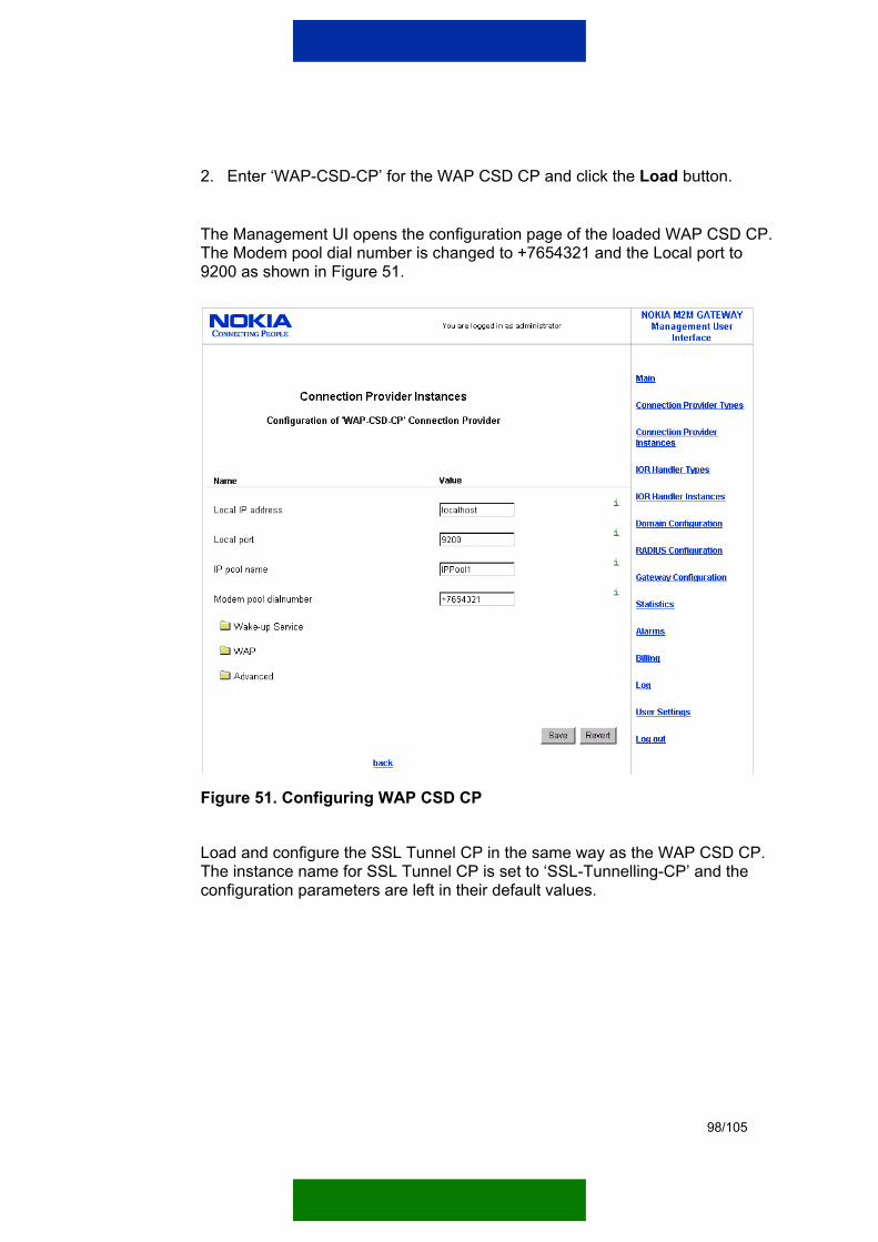
98/105
2. Enter ‘WAP-CSD-CP’ for the WAP CSD CP and click the Load button.
The Management UI opens the configuration page of the loaded WAP CSD CP. The Modem pool dial number is changed to +7654321 and the Local port to 9200 as shown in Figure 51.
Figure 51. Configuring WAP CSD CP
Load and configure the SSL Tunnel CP in the same way as the WAP CSD CP. The instance name for SSL Tunnel CP is set to ‘SSL-Tunnelling-CP’ and the configuration parameters are left in their default values.
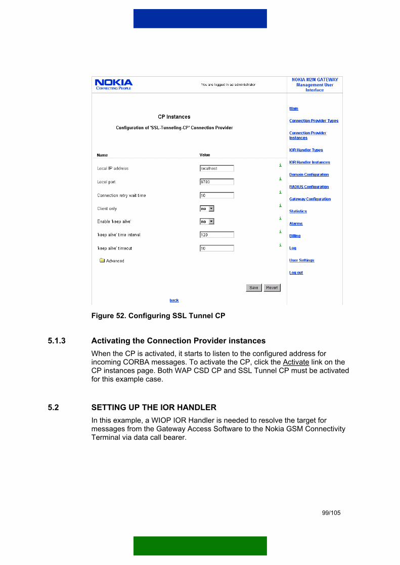
99/105
Figure 52. Configuring SSL Tunnel CP
5.1.3 Activating the Connection Provider instances When the CP is activated, it starts to listen to the configured address for incoming CORBA messages. To activate the CP, click the Activate link on the CP instances page. Both WAP CSD CP and SSL Tunnel CP must be activated for this example case.
5.2 SETTING UP THE IOR HANDLER In this example, a WIOP IOR Handler is needed to resolve the target for messages from the Gateway Access Software to the Nokia GSM Connectivity Terminal via data call bearer.
100/105
5.2.1 Installing the IOR Handler type
To install the WIOP IOR Handler: 1. Open the IOR Handler Types page by clicking the IOR Handler Types link
on the right side of the Management UI. 2. Open the installation page by clicking the Install new IOR Handler type link
on the IOR Handler Types page. 3. Browse for the ior_handler_wiop-4.x.x.jar file in the [Gateway installation
path]/ior handler directory and click the Install button.
5.2.2 Loading and configuring the IOR Handler instance When the IOR Handler type is installed, its IOR Handler instance must be loaded.
To load and configure an IOR Handler instance for WIOP IOR Handler: 1. Click the Load new instance link on the IOR Handler Types page. A new
page is displayed where you need to enter an instance name for the IOR Handler.
2. Enter ‘WIOP-IOR-Handler’ for the WIOP IOR Handler and click the Load button.
There are no configurable parameters for the WIOP IOR Handler in the Gateway. The WIOP IOR Handler obtains all the needed parameters from the domain configuration.
5.2.3 Activating the IOR Handler instance When the IOR Handler is activated, it can resolve target addresses for incoming messages. To activate the IOR Handler, click the Activate link on the IOR Handler Instances page. In this example, only the WIOP IOR Handler must be activated.
5.3 SETTING UP THE DOMAIN Domain configuration defines the address of the Gateway Access Software domain that the CPs use to communicate with the Nokia GSM Connectivity Terminal. It also defines the billing information that needs to be generated and some miscellaneous settings for the domain. The domain must be created, configured, and activated for it to work properly.
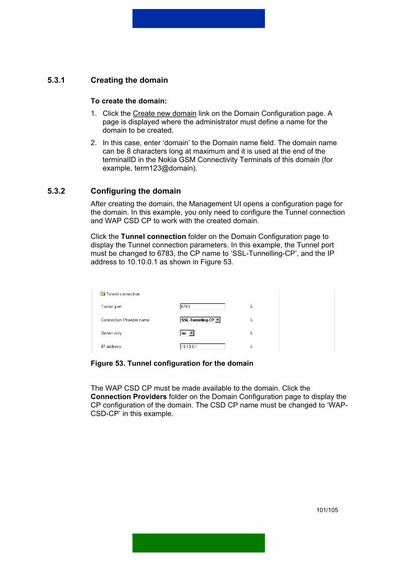
101/105
5.3.1 Creating the domain
To create the domain: 1. Click the Create new domain link on the Domain Configuration page. A
page is displayed where the administrator must define a name for the domain to be created.
2. In this case, enter ‘domain’ to the Domain name field. The domain name can be 8 characters long at maximum and it is used at the end of the terminalID in the Nokia GSM Connectivity Terminals of this domain (for example, term123@domain).
5.3.2 Configuring the domain After creating the domain, the Management UI opens a configuration page for the domain. In this example, you only need to configure the Tunnel connection and WAP CSD CP to work with the created domain.
Click the Tunnel connection folder on the Domain Configuration page to display the Tunnel connection parameters. In this example, the Tunnel port must be changed to 6783, the CP name to ‘SSL-Tunnelling-CP’, and the IP address to 10.10.0.1 as shown in Figure 53.
Figure 53. Tunnel configuration for the domain
The WAP CSD CP must be made available to the domain. Click the Connection Providers folder on the Domain Configuration page to display the CP configuration of the domain. The CSD CP name must be changed to ‘WAP-CSD-CP’ in this example.
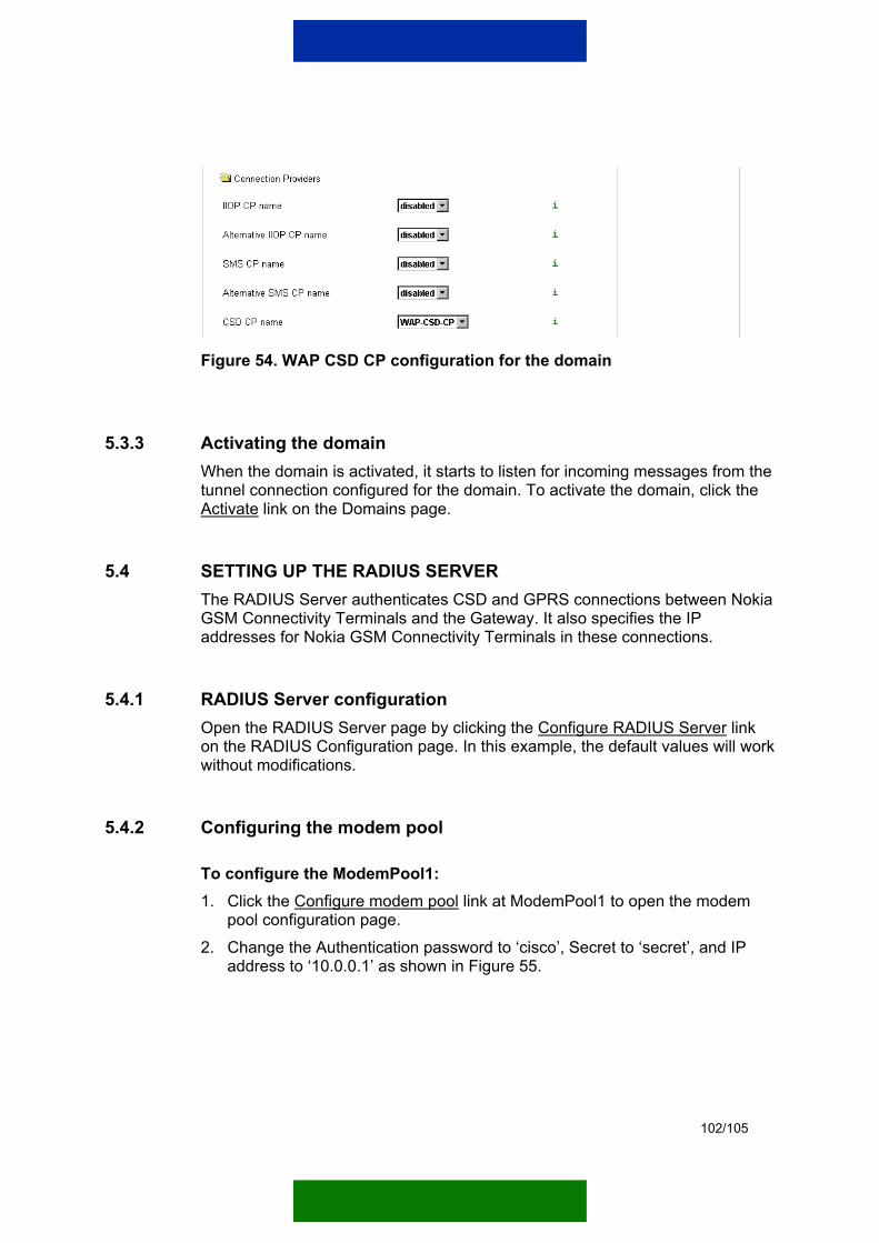
102/105
Figure 54. WAP CSD CP configuration for the domain
5.3.3 Activating the domain When the domain is activated, it starts to listen for incoming messages from the tunnel connection configured for the domain. To activate the domain, click the Activate link on the Domains page.
5.4 SETTING UP THE RADIUS SERVER The RADIUS Server authenticates CSD and GPRS connections between Nokia GSM Connectivity Terminals and the Gateway. It also specifies the IP addresses for Nokia GSM Connectivity Terminals in these connections.
5.4.1 RADIUS Server configuration Open the RADIUS Server page by clicking the Configure RADIUS Server link on the RADIUS Configuration page. In this example, the default values will work without modifications.
5.4.2 Configuring the modem pool
To configure the ModemPool1: 1. Click the Configure modem pool link at ModemPool1 to open the modem
pool configuration page. 2. Change the Authentication password to ‘cisco’, Secret to ‘secret’, and IP
address to ‘10.0.0.1’ as shown in Figure 55.
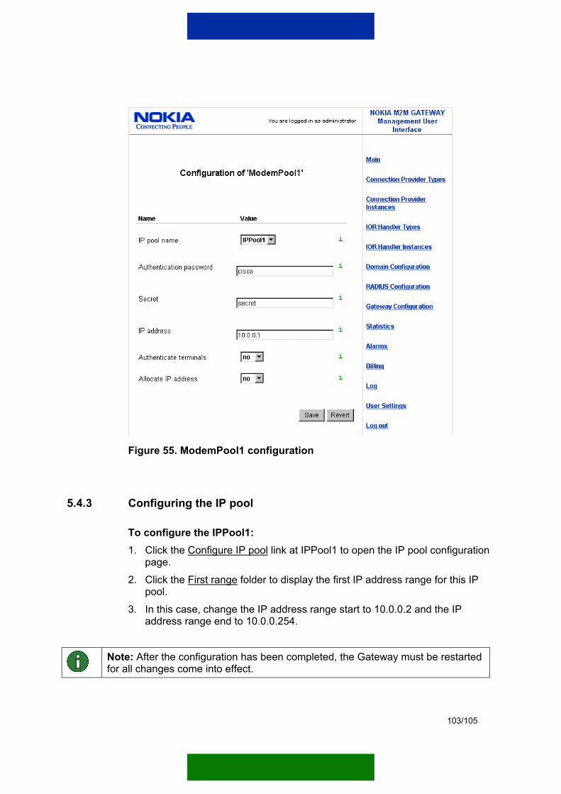
103/105
Figure 55. ModemPool1 configuration
5.4.3 Configuring the IP pool
To configure the IPPool1: 1. Click the Configure IP pool link at IPPool1 to open the IP pool configuration
page. 2. Click the First range folder to display the first IP address range for this IP
pool. 3. In this case, change the IP address range start to 10.0.0.2 and the IP
address range end to 10.0.0.254.
Note: After the configuration has been completed, the Gateway must be restarted for all changes come into effect.
104/105
5.4.4 Configuring the route and Cisco 3620 You must define a route for all the IP addresses (defined in the IP pool settings of the Gateway) in the operating system to the correct Cisco 3620 or GPRS access point. According to route definitions, the operating system is able to route IP packets sent by the Gateway to the correct destination.
5.4.4.1 Making the route definition in Windows A route is set in the operating system of the Gateway that refers all the communications of a Nokia GSM Connectivity Terminal to Cisco 3620. Because in this example the IP addresses assigned to Nokia GSM Connectivity Terminals are between 10.0.0.2 and 10.0.0.254 and use data call connection, all IP packets with 10.0.0.x addresses are sent to Cisco 3620.
Write the following text into the command prompt:
route add –p 10.0.0.0 mask 255.255.255.0 10.10.10.10
5.4.4.2 Configuring Cisco 3620 Log into the Cisco 3620 configuration via Telnet connection and enter the following changes:
IP name-server 10.10.10.11 The Service Provider Edition is used as the Naming Service, because it has a built-in Domain Name Server (DNS).
IP route 10.0.0.0 255.255.255.0 Dialer0 All communications that are targeted to IP addresses of Nokia GSM Connectivity Terminals are sent to the dialler interface that manages the calls.
Radius-server host 10.10.10.11 auth-port 1812 acct-port 1813 RADIUS server can be obtained from the Gateway using the given IP address and ports. These have already been configured in the RADIUS Server.
Radius-server key secret The same password is entered here that was entered earlier into the RADIUS Server.
5.5 CONFIGURING THE GATEWAY ACCESS SOFTWARE The Gateway Access Software must be configured to communicate with the Gateway, and the Nokia GSM Connectivity Terminal setting must be added into

105/105
DIS. DIS is described in more detail in the Nokia M2M Platform Device Information Storage Programming Guide.
5.5.1 Installing credentials for the SSL connection The service provider delivers SSL credentials for SSL connections as a keydb.jar file. This file must be copied into the Gateway Access Software installation directory.
5.5.2 Configuring the Gateway address You need to define the IP address and port of the Gateway in the access_software_ssl.properties file. This file is located in the lib directory of the Gateway Access Software. In this example, the parameter values are:
wipunen.domains.defaultDomain.primaryTunnel.port=6783 wipunen.domains.defaultDomain.primaryTunnel.serverOnly=no wipunen.domains.defaultDomain.primaryTunnel.ipAddress=10.10.10.11
5.5.3 Configuring the Device Information Storage reference implementation With the Gateway Access Software comes a reference implementation of DIS that reads the configuration information of the Nokia GSM Connectivity Terminal from the user_information.txt file. This file is located in the bin directory of the Gateway Access Software.
In this example, the DIS entry looks as follows:
term123.localpassword=password term123.remoteusername=term123 term123.remotepassword=password term123.ipaddress= term123.smsmsisdn= term123.csdmsisdn=+1234567
The reference implementation of DIS can be started from the bin directory of the Gateway Access Software by running one of the following files (depending on the used ORB):
• device_information_storage_visibroker.bat • device_information_storage_jacorb.bat • device_information_storage_visibroker.sh • device_information_storage_jacorb.sh