Embed Size (px)
Citation preview
Check the repair policy before
performing any mechanical repair on Service Level
1&2!
Service Manual for L1 and L2
Nokia Lumia 1020RM-877Key features
1.5 GHz Qualcomm dual-core processor 2 GB RAM and 32 GB of internal storage 4.5" AMOLED Puremotion HD+ display 41 Mpix PureView camera with OIS 2G / 3G / 4G LTE connectivity
Version 2.0
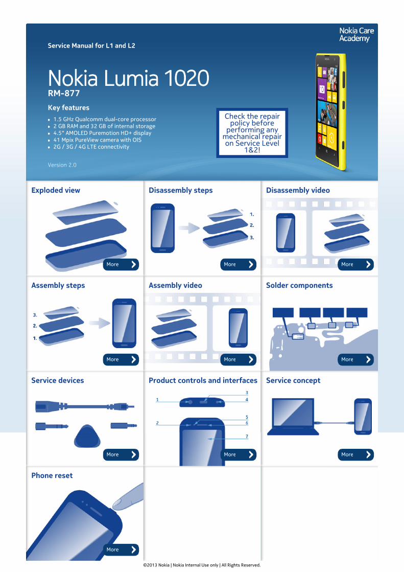
Exploded view Disassembly steps Disassembly video
Assembly steps Assembly video Solder components
Service devices Product controls and interfaces Service concept
Phone reset
©2013 Nokia | Nokia Internal Use only | All Rights Reserved.
More More More
More More More
More More More
More
Service Manual Level 1 and 2
Nokia Lumia 1020RM-877Version 2.0
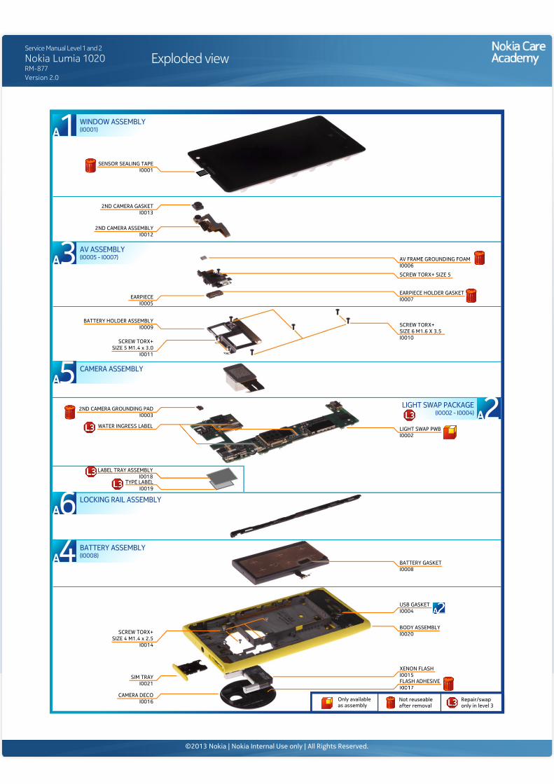
Exploded view
2ND CAMERA GASKETI0013
EARPIECEI0005
2ND CAMERA GROUNDING PADI0003
LIGHT SWAP PWBI0002
CAMERA DECOI0016
SIM TRAYI0021
BATTERY HOLDER ASSEMBLYI0009
2ND CAMERA ASSEMBLYI0012
SENSOR SEALING TAPEI0001
WATER INGRESS LABEL
LABEL TRAY ASSEMBLYI0018
EARPIECE HOLDER GASKETI0007
AV FRAME GROUNDING FOAMI0006
USB GASKETI0004
TYPE LABELI0019
BATTERY GASKETI0008
XENON FLASH I0015FLASH ADHESIVE
BODY ASSEMBLY I0020
SCREW TORX+ SIZE 6 M1.6 X 3.5I0010
SCREW TORX+ SIZE 5
SCREW TORX+SIZE 5 M1.4 x 3.0
I0011
SCREW TORX+SIZE 4 M1.4 x 2.5
I0014
CAMERA ASSEMBLY5
WINDOW ASSEMBLY(I0001)1
AV ASSEMBLY(I0005 - I0007)3
LOCKING RAIL ASSEMBLY6BATTERY ASSEMBLY(I0008)4
LIGHT SWAP PACKAGE(I0002 - I0004) 2
Only availableas assembly
Not reuseableafter removal
Repair/swaponly in level 3
©2013 Nokia | Nokia Internal Use only | All Rights Reserved.
Service Manual Level 1 and 2
Nokia Lumia 1020RM-877Version 2.0
Disassembly steps
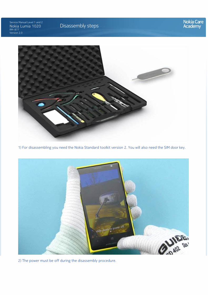
1) For disassembling you need the Nokia Standard toolkit version 2. You will also need the SIM door key.
2) The power must be off during the disassembly procedure.
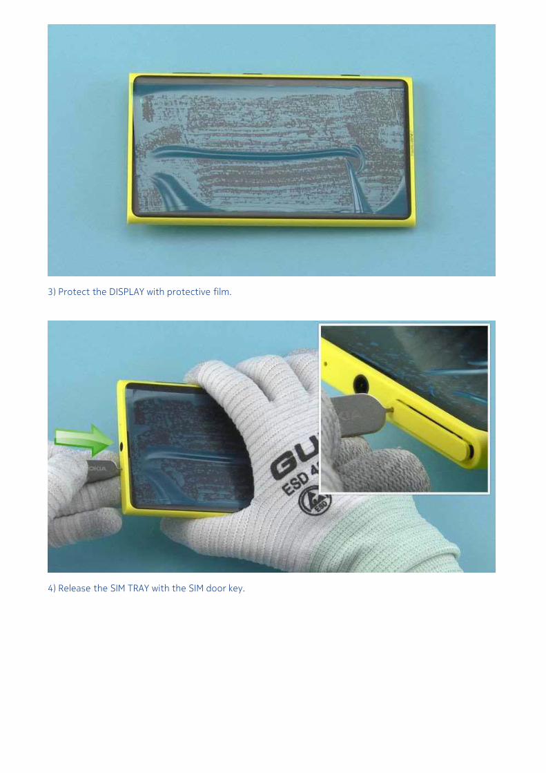
3) Protect the DISPLAY with protective film.
4) Release the SIM TRAY with the SIM door key.
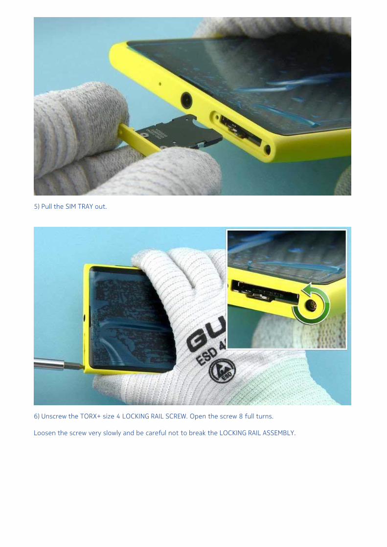
5) Pull the SIM TRAY out.
6) Unscrew the TORX+ size 4 LOCKING RAIL SCREW. Open the screw 8 full turns.
Loosen the screw very slowly and be careful not to break the LOCKING RAIL ASSEMBLY.
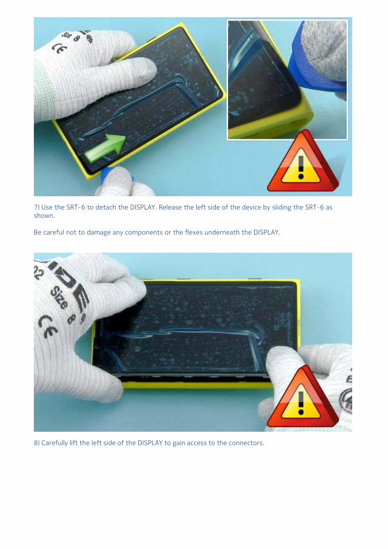
7) Use the SRT-6 to detach the DISPLAY. Release the left side of the device by sliding the SRT-6 asshown.
Be careful not to damage any components or the flexes underneath the DISPLAY.
8) Carefully lift the left side of the DISPLAY to gain access to the connectors.
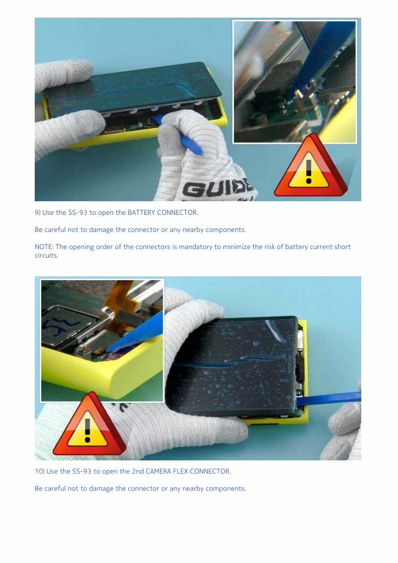
9) Use the SS-93 to open the BATTERY CONNECTOR.
Be careful not to damage the connector or any nearby components.
NOTE: The opening order of the connectors is mandatory to minimize the risk of battery current shortcircuits.
10) Use the SS-93 to open the 2nd CAMERA FLEX CONNECTOR.
Be careful not to damage the connector or any nearby components.
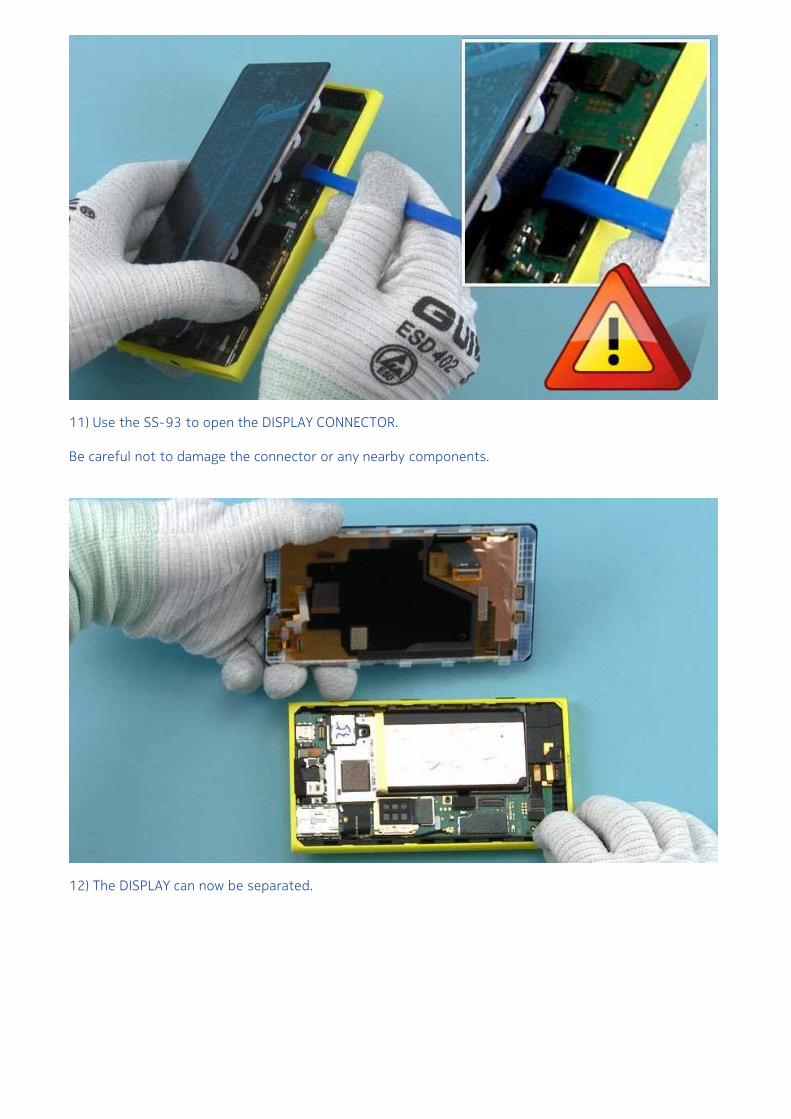
11) Use the SS-93 to open the DISPLAY CONNECTOR.
Be careful not to damage the connector or any nearby components.
12) The DISPLAY can now be separated.
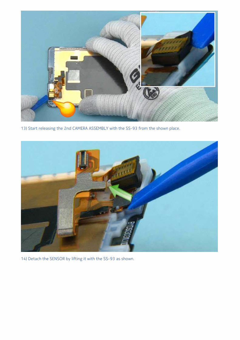
13) Start releasing the 2nd CAMERA ASSEMBLY with the SS-93 from the shown place.
14) Detach the SENSOR by lifting it with the SS-93 as shown.
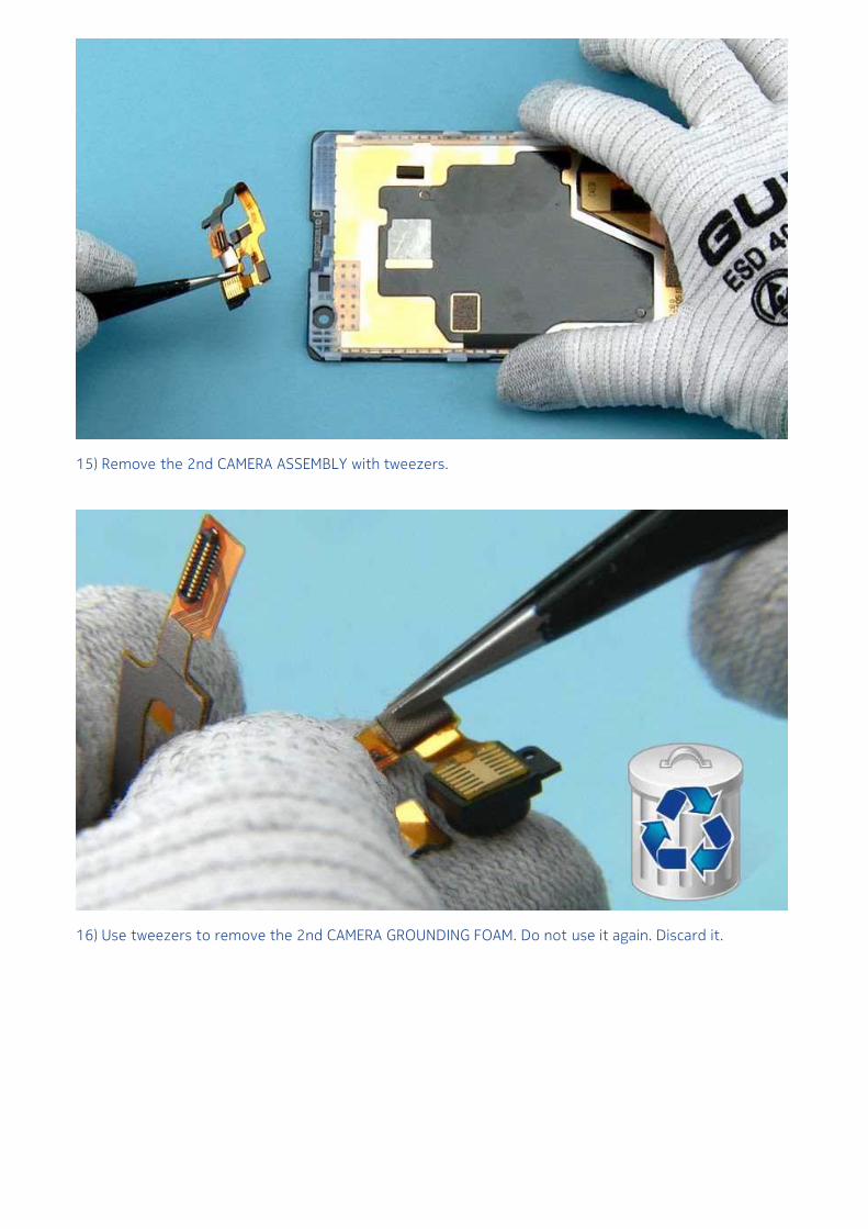
15) Remove the 2nd CAMERA ASSEMBLY with tweezers.
16) Use tweezers to remove the 2nd CAMERA GROUNDING FOAM. Do not use it again. Discard it.
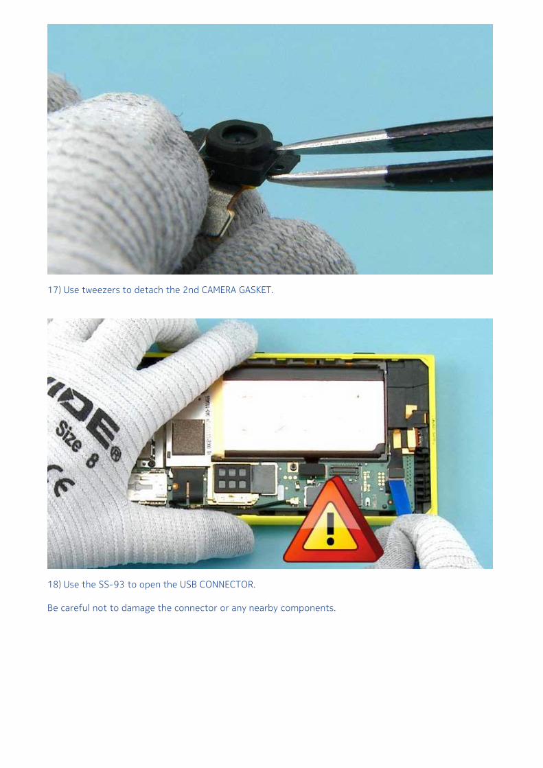
17) Use tweezers to detach the 2nd CAMERA GASKET.
18) Use the SS-93 to open the USB CONNECTOR.
Be careful not to damage the connector or any nearby components.
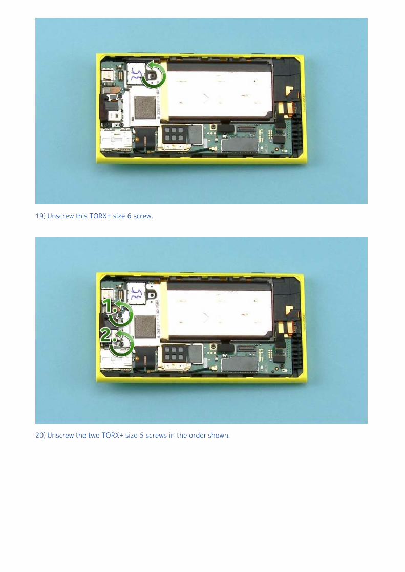
19) Unscrew this TORX+ size 6 screw.
20) Unscrew the two TORX+ size 5 screws in the order shown.
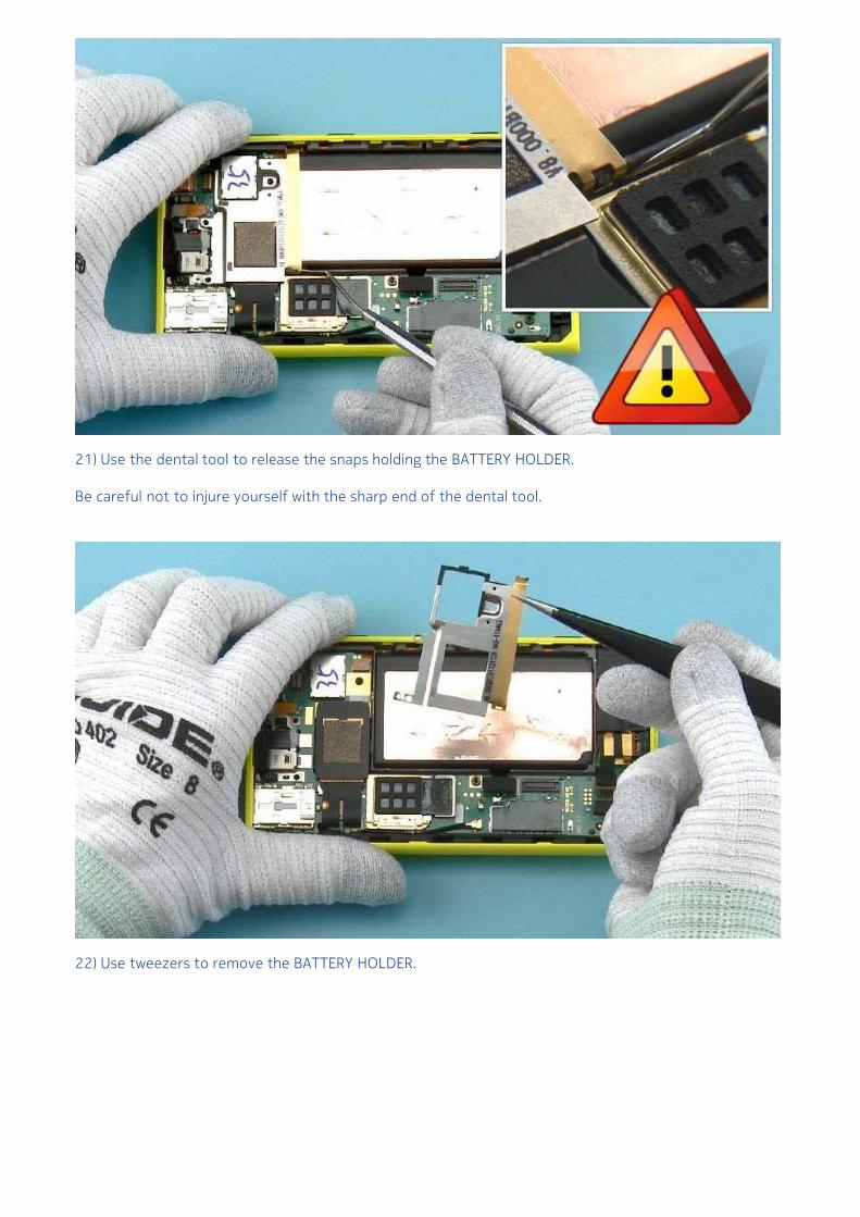
21) Use the dental tool to release the snaps holding the BATTERY HOLDER.
Be careful not to injure yourself with the sharp end of the dental tool.
22) Use tweezers to remove the BATTERY HOLDER.
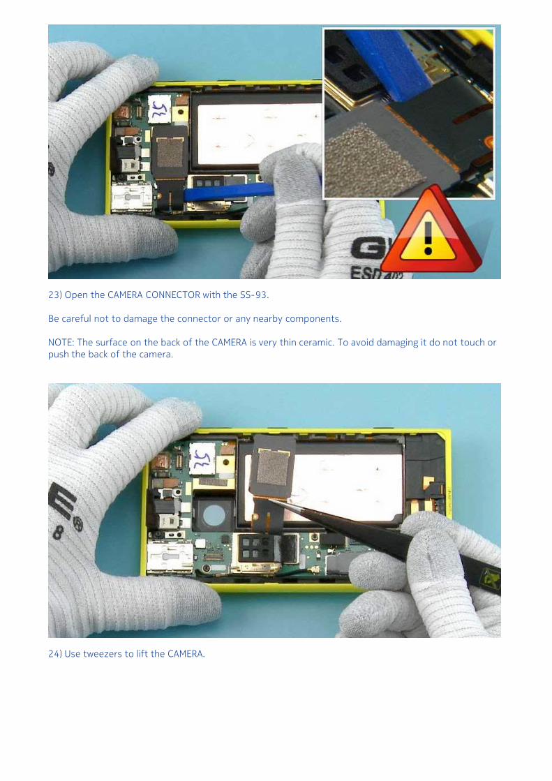
23) Open the CAMERA CONNECTOR with the SS-93.
Be careful not to damage the connector or any nearby components.
NOTE: The surface on the back of the CAMERA is very thin ceramic. To avoid damaging it do not touch orpush the back of the camera.
24) Use tweezers to lift the CAMERA.
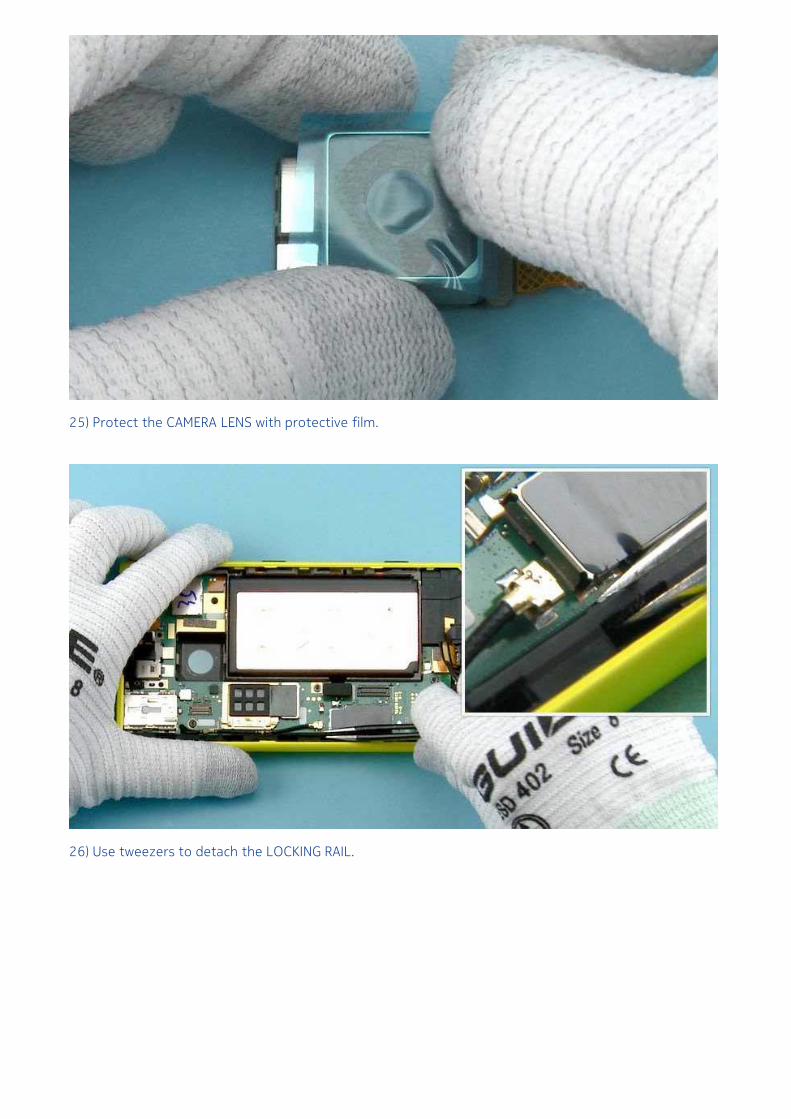
25) Protect the CAMERA LENS with protective film.
26) Use tweezers to detach the LOCKING RAIL.
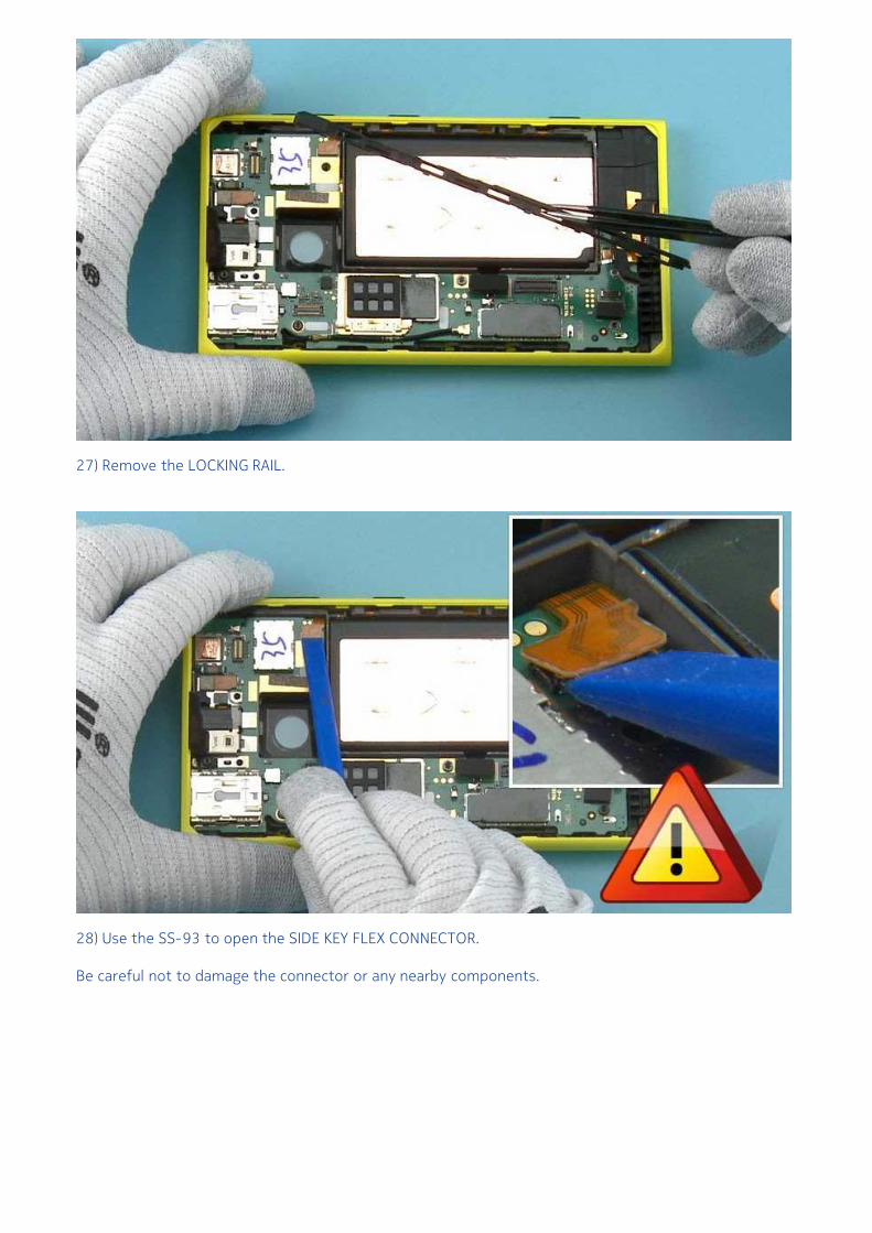
27) Remove the LOCKING RAIL.
28) Use the SS-93 to open the SIDE KEY FLEX CONNECTOR.
Be careful not to damage the connector or any nearby components.
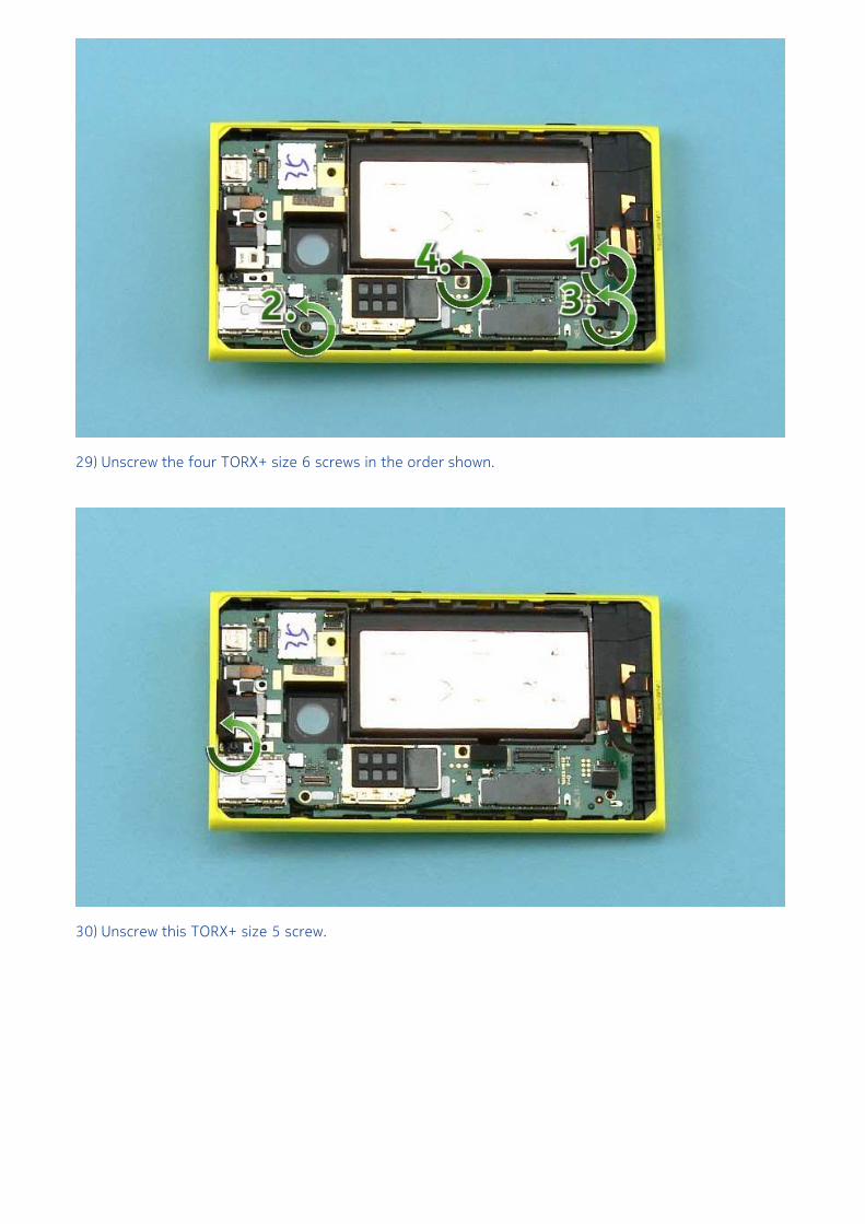
29) Unscrew the four TORX+ size 6 screws in the order shown.
30) Unscrew this TORX+ size 5 screw.
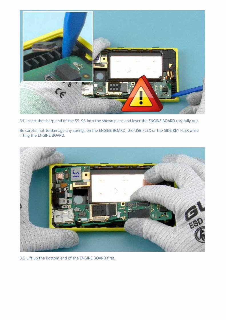
31) Insert the sharp end of the SS-93 into the shown place and lever the ENGINE BOARD carefully out.
Be careful not to damage any springs on the ENGINE BOARD, the USB FLEX or the SIDE KEY FLEX whilelifting the ENGINE BOARD.
32) Lift up the bottom end of the ENGINE BOARD first.
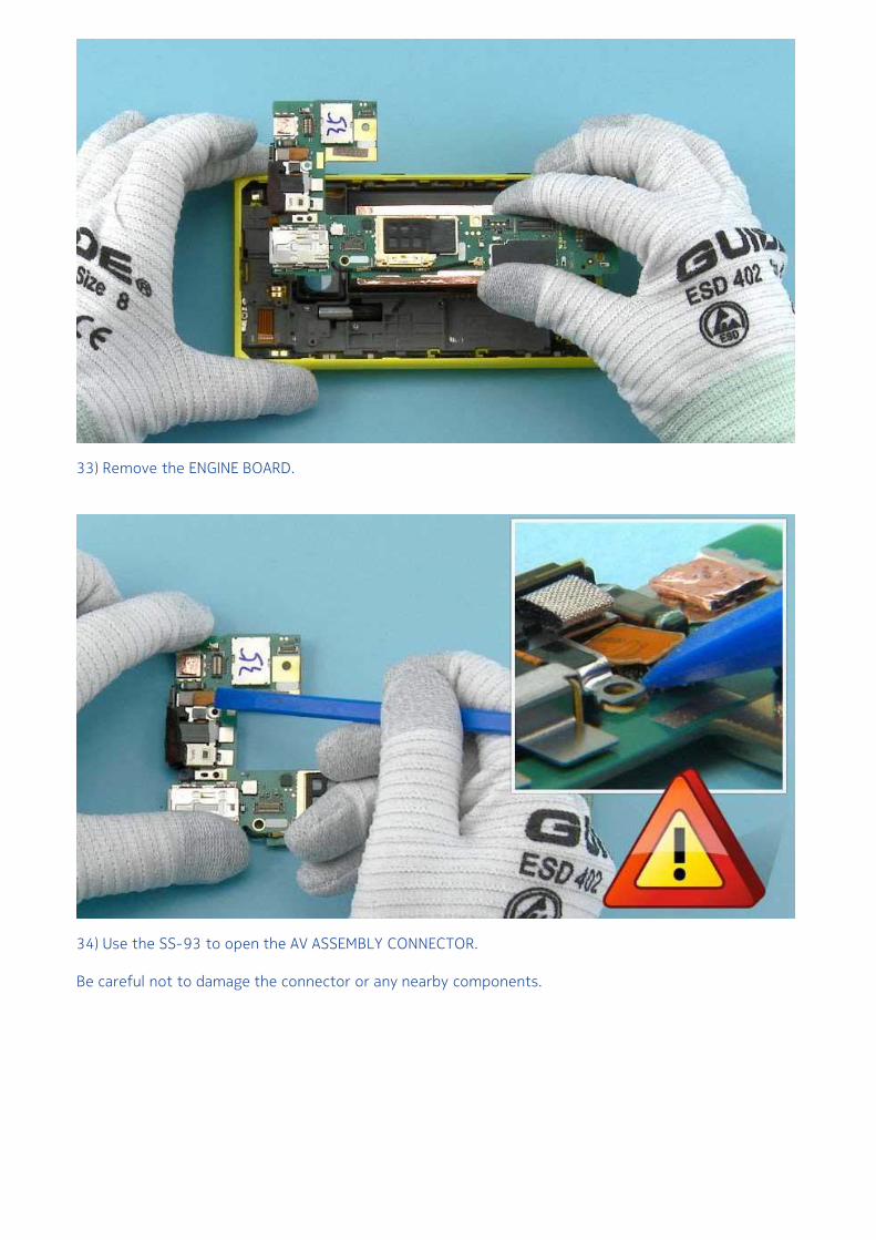
33) Remove the ENGINE BOARD.
34) Use the SS-93 to open the AV ASSEMBLY CONNECTOR.
Be careful not to damage the connector or any nearby components.
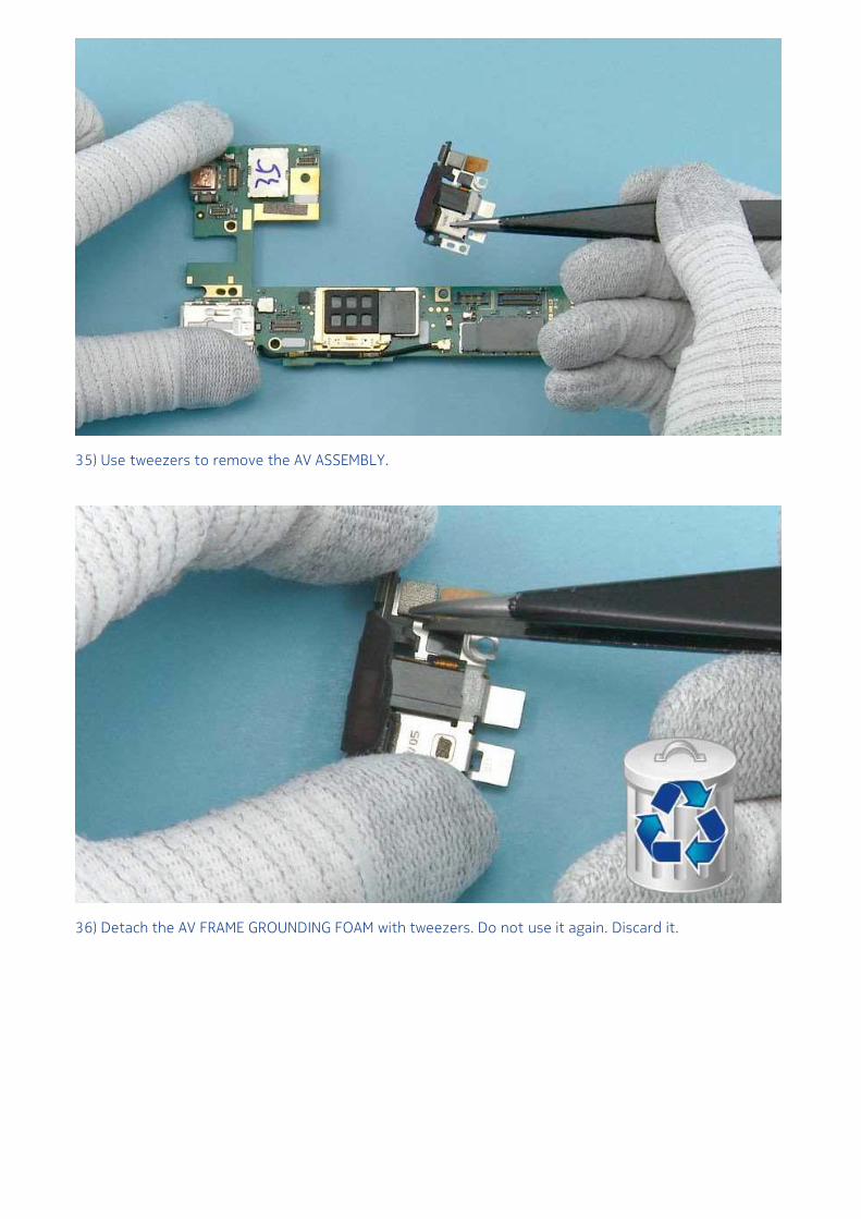
35) Use tweezers to remove the AV ASSEMBLY.
36) Detach the AV FRAME GROUNDING FOAM with tweezers. Do not use it again. Discard it.
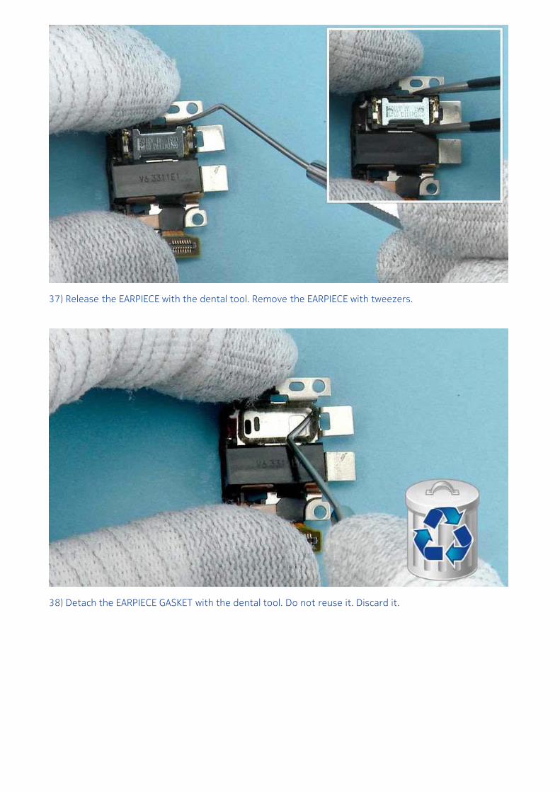
37) Release the EARPIECE with the dental tool. Remove the EARPIECE with tweezers.
38) Detach the EARPIECE GASKET with the dental tool. Do not reuse it. Discard it.
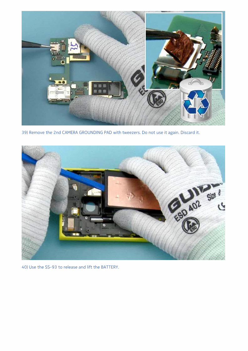
39) Remove the 2nd CAMERA GROUNDING PAD with tweezers. Do not use it again. Discard it.
40) Use the SS-93 to release and lift the BATTERY.
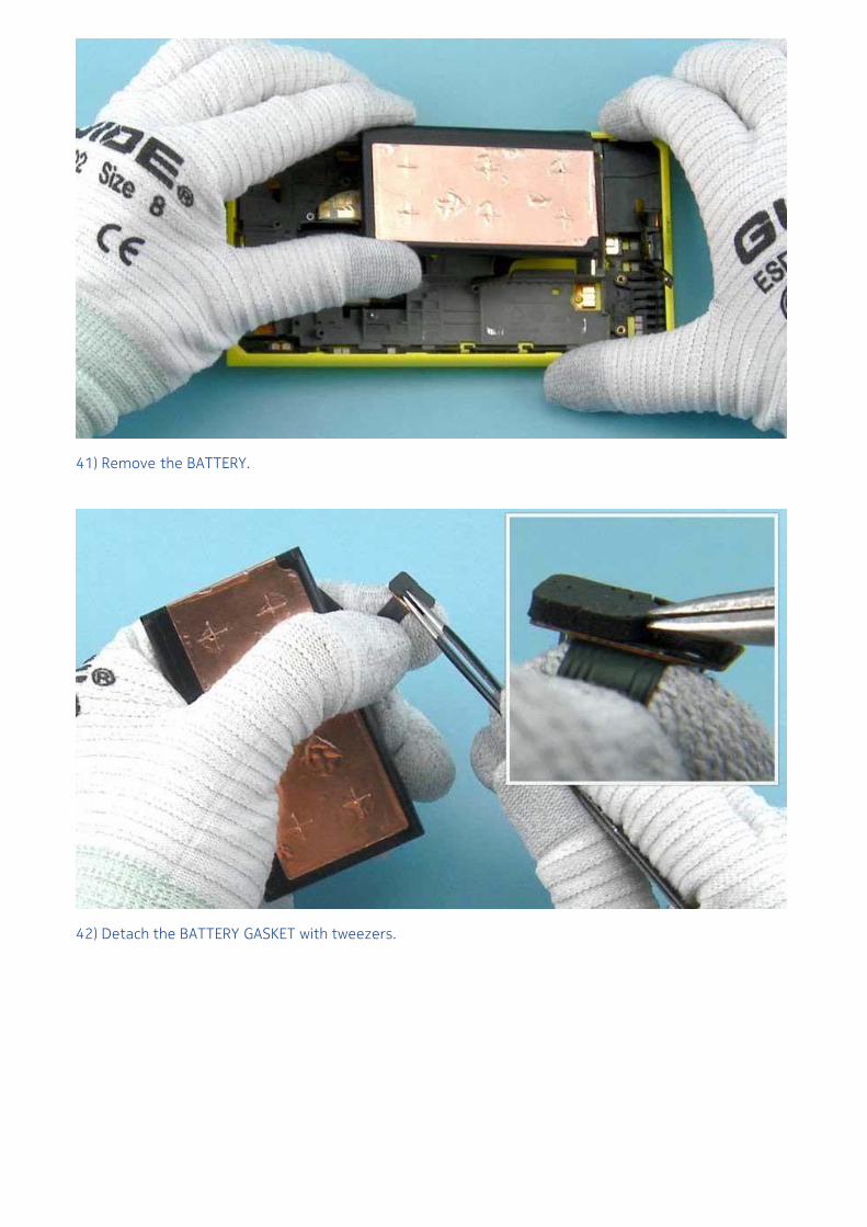
41) Remove the BATTERY.
42) Detach the BATTERY GASKET with tweezers.
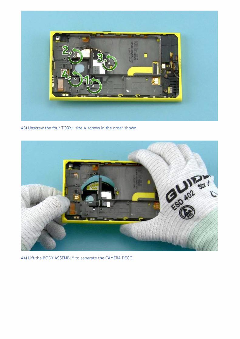
43) Unscrew the four TORX+ size 4 screws in the order shown.
44) Lift the BODY ASSEMBLY to separate the CAMERA DECO.
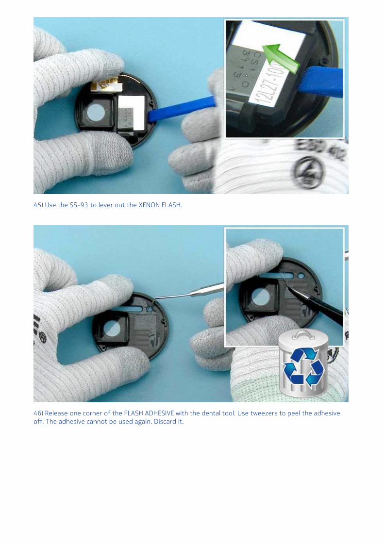
45) Use the SS-93 to lever out the XENON FLASH.
46) Release one corner of the FLASH ADHESIVE with the dental tool. Use tweezers to peel the adhesiveoff. The adhesive cannot be used again. Discard it.
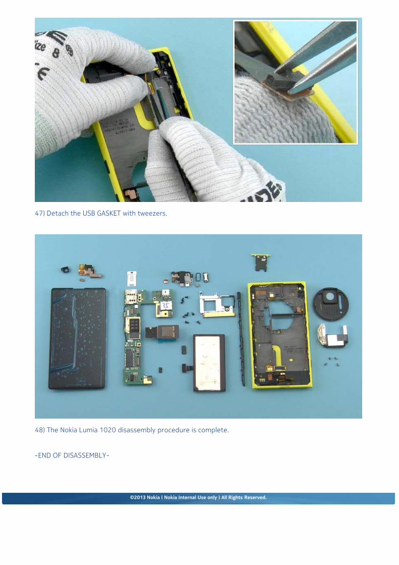
47) Detach the USB GASKET with tweezers.
48) The Nokia Lumia 1020 disassembly procedure is complete.
-END OF DISASSEMBLY-
©2013 Nokia | Nokia Internal Use only | All Rights Reserved.
Service Manual Level 1 and 2
Nokia Lumia 1020RM-877Version 2.0
Assembly steps
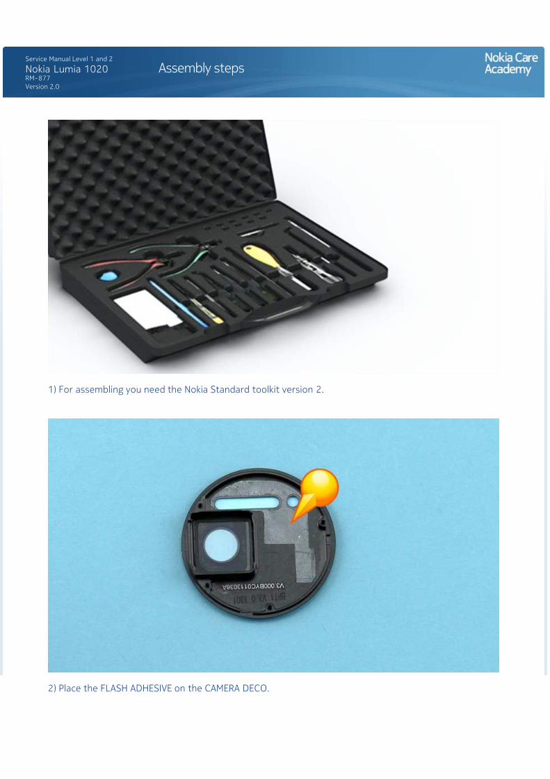
1) For assembling you need the Nokia Standard toolkit version 2.
2) Place the FLASH ADHESIVE on the CAMERA DECO.
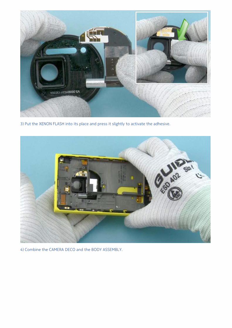
3) Put the XENON FLASH into its place and press it slightly to activate the adhesive.
4) Combine the CAMERA DECO and the BODY ASSEMBLY.
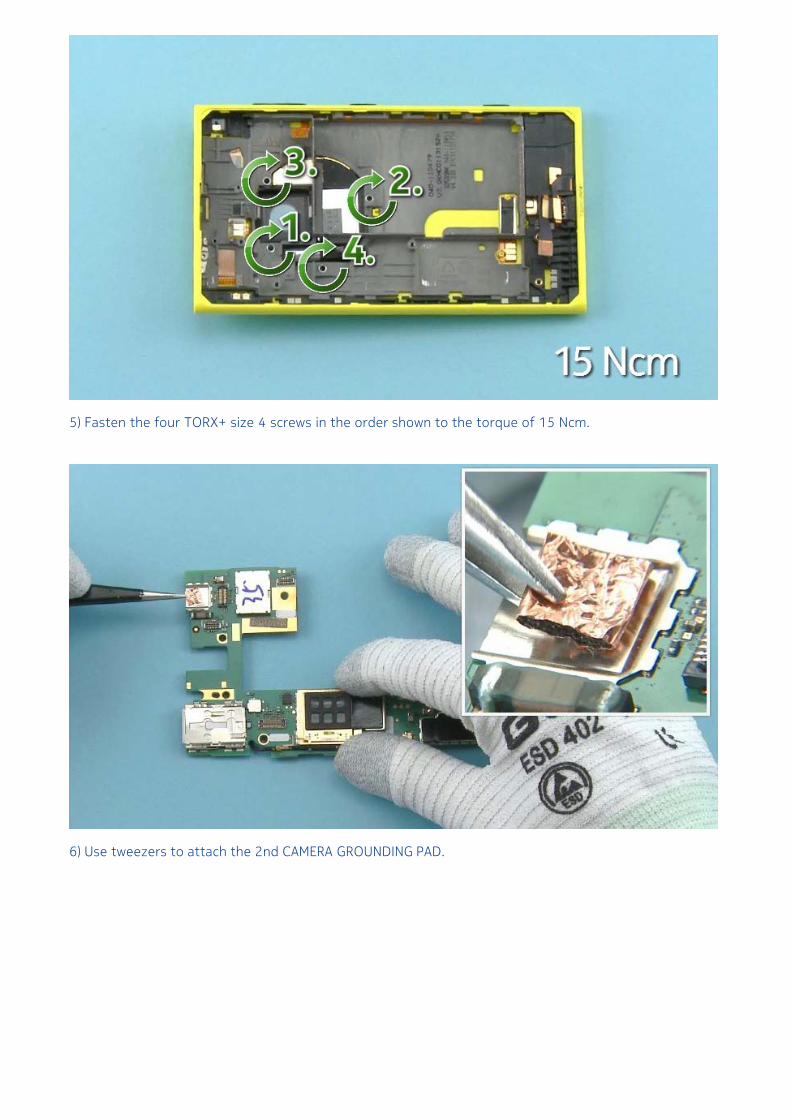
5) Fasten the four TORX+ size 4 screws in the order shown to the torque of 15 Ncm.
6) Use tweezers to attach the 2nd CAMERA GROUNDING PAD.
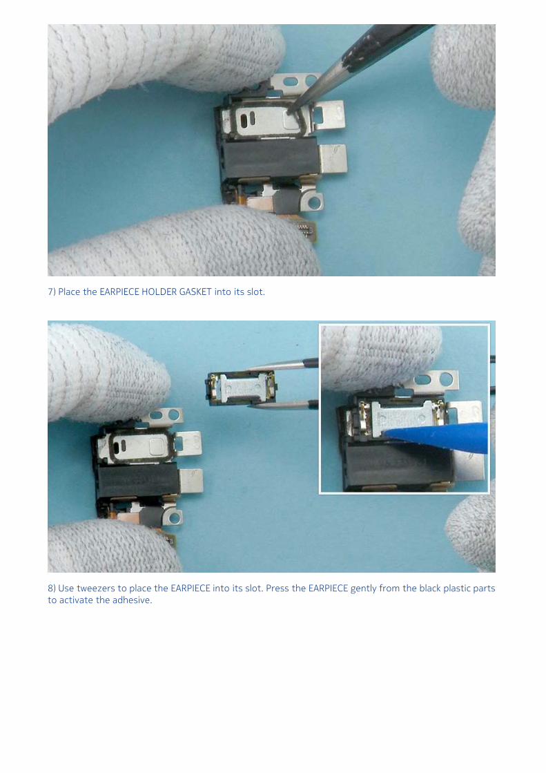
7) Place the EARPIECE HOLDER GASKET into its slot.
8) Use tweezers to place the EARPIECE into its slot. Press the EARPIECE gently from the black plastic partsto activate the adhesive.
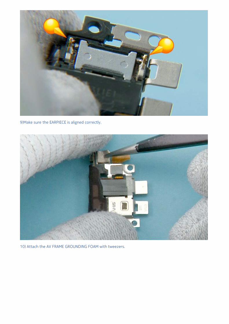
9)Make sure the EARPIECE is aligned correctly.
10) Attach the AV FRAME GROUNDING FOAM with tweezers.
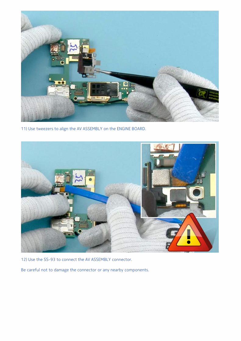
11) Use tweezers to align the AV ASSEMBLY on the ENGINE BOARD.
12) Use the SS-93 to connect the AV ASSEMBLY connector.
Be careful not to damage the connector or any nearby components.
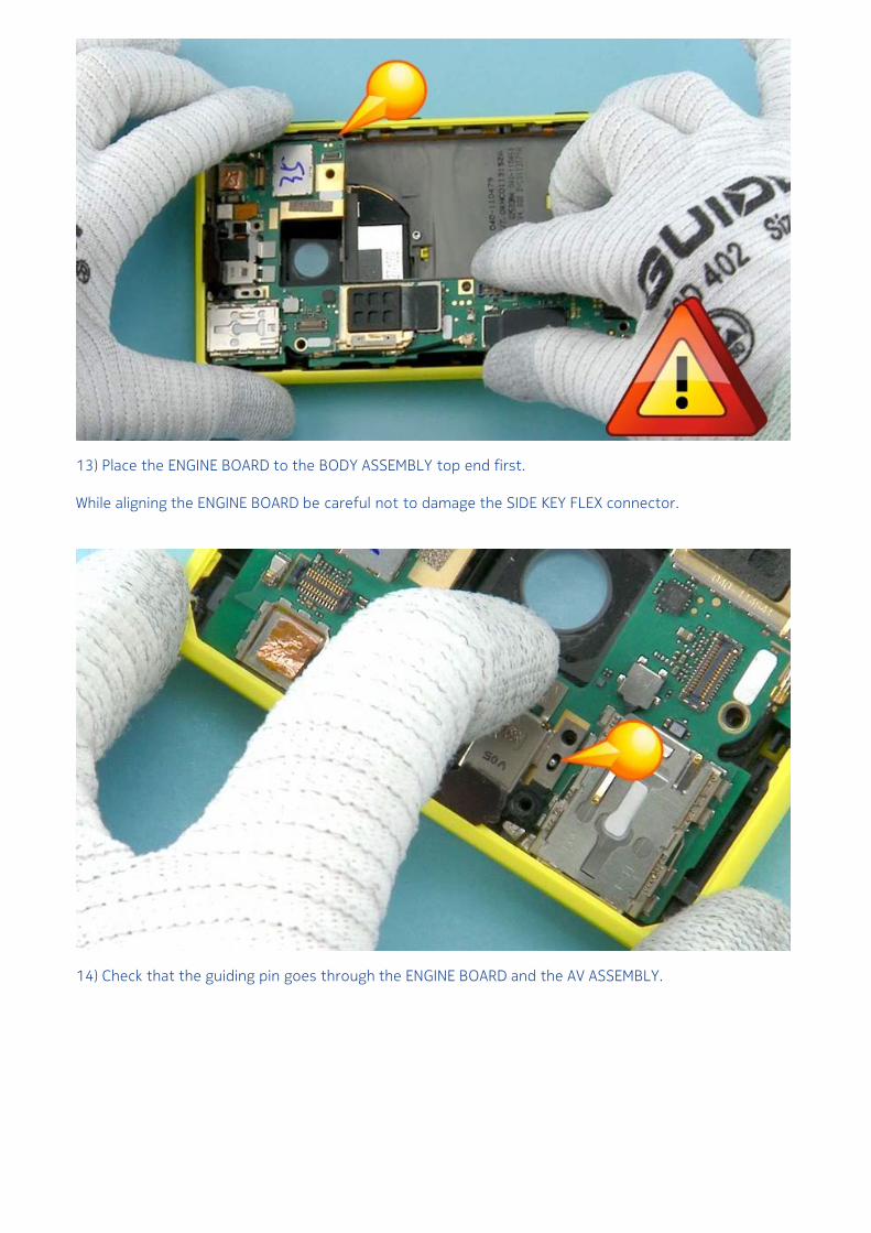
13) Place the ENGINE BOARD to the BODY ASSEMBLY top end first.
While aligning the ENGINE BOARD be careful not to damage the SIDE KEY FLEX connector.
14) Check that the guiding pin goes through the ENGINE BOARD and the AV ASSEMBLY.
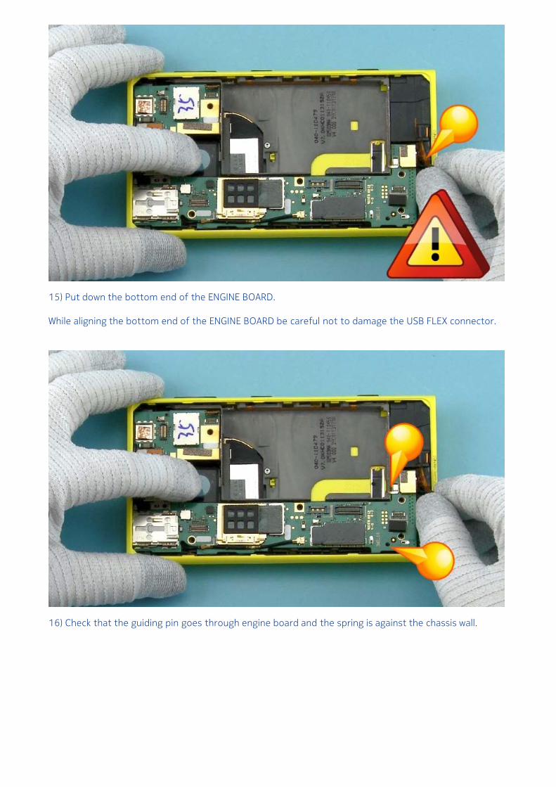
15) Put down the bottom end of the ENGINE BOARD.
While aligning the bottom end of the ENGINE BOARD be careful not to damage the USB FLEX connector.
16) Check that the guiding pin goes through engine board and the spring is against the chassis wall.
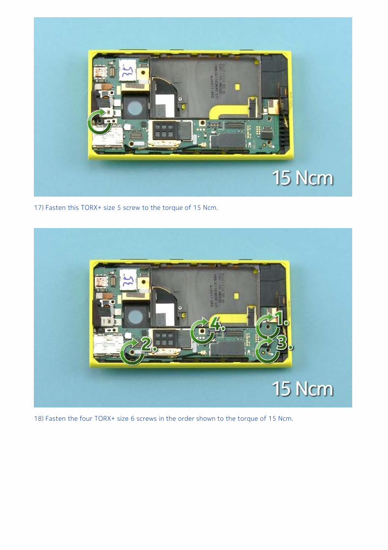
17) Fasten this TORX+ size 5 screw to the torque of 15 Ncm.
18) Fasten the four TORX+ size 6 screws in the order shown to the torque of 15 Ncm.
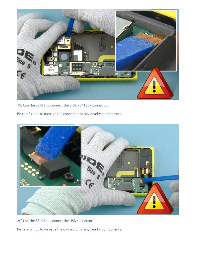
19) Use the SS-93 to connect the SIDE KEY FLEX connector.
Be careful not to damage the connector or any nearby components.
20) Use the SS-93 to connect the USB connector.
Be careful not to damage the connector or any nearby components.
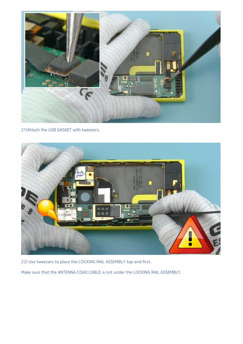
21)Attach the USB GASKET with tweezers.
22) Use tweezers to place the LOCKING RAIL ASSEMBLY top end first.
Make sure that the ANTENNA COAX CABLE is not under the LOCKING RAIL ASSEMBLY.
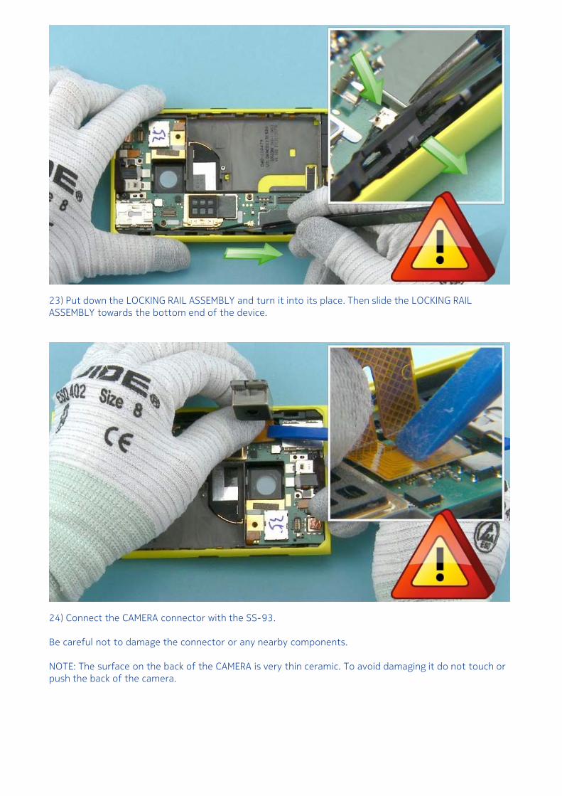
23) Put down the LOCKING RAIL ASSEMBLY and turn it into its place. Then slide the LOCKING RAILASSEMBLY towards the bottom end of the device.
24) Connect the CAMERA connector with the SS-93.
Be careful not to damage the connector or any nearby components.
NOTE: The surface on the back of the CAMERA is very thin ceramic. To avoid damaging it do not touch orpush the back of the camera.
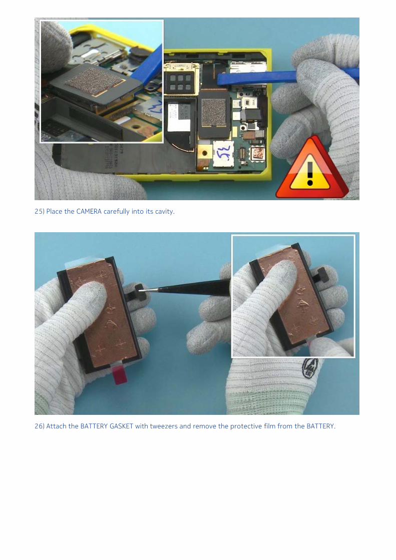
25) Place the CAMERA carefully into its cavity.
26) Attach the BATTERY GASKET with tweezers and remove the protective film from the BATTERY.
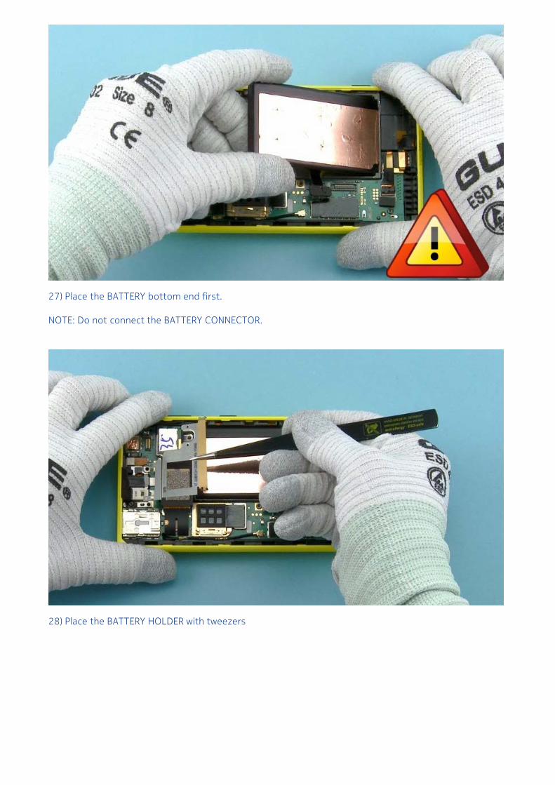
27) Place the BATTERY bottom end first.
NOTE: Do not connect the BATTERY CONNECTOR.
28) Place the BATTERY HOLDER with tweezers
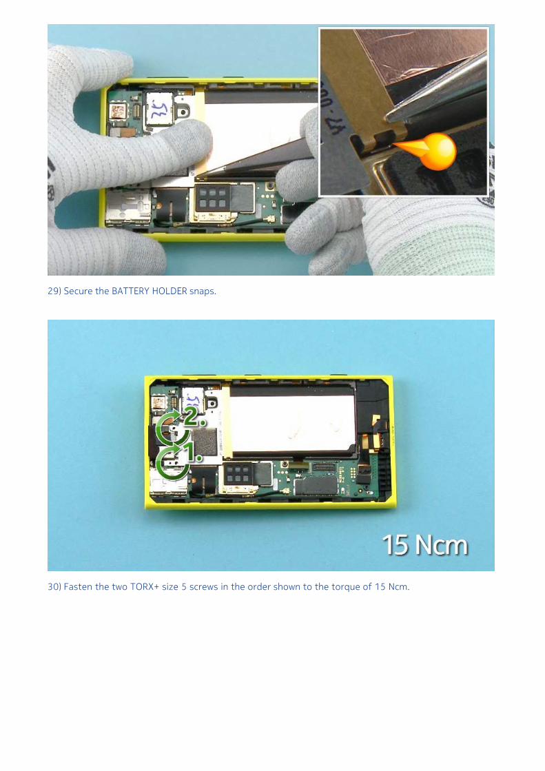
29) Secure the BATTERY HOLDER snaps.
30) Fasten the two TORX+ size 5 screws in the order shown to the torque of 15 Ncm.
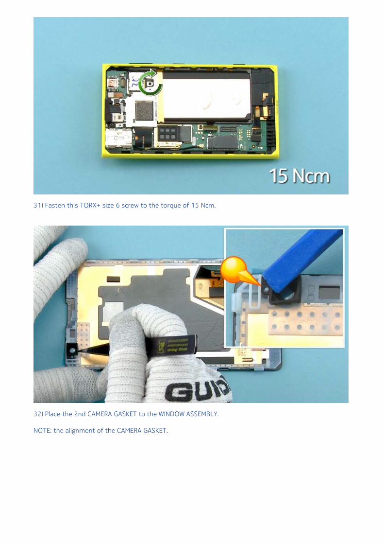
31) Fasten this TORX+ size 6 screw to the torque of 15 Ncm.
32) Place the 2nd CAMERA GASKET to the WINDOW ASSEMBLY.
NOTE: the alignment of the CAMERA GASKET.
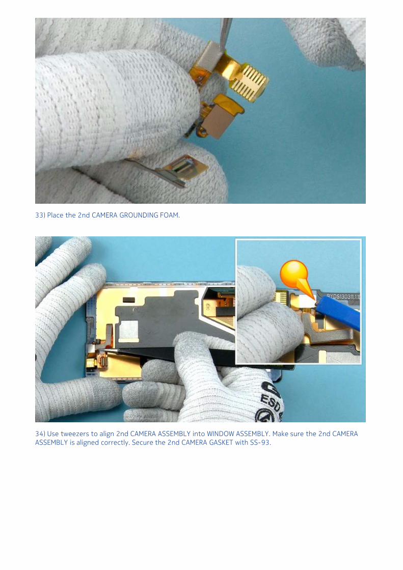
33) Place the 2nd CAMERA GROUNDING FOAM.
34) Use tweezers to align 2nd CAMERA ASSEMBLY into WINDOW ASSEMBLY. Make sure the 2nd CAMERAASSEMBLY is aligned correctly. Secure the 2nd CAMERA GASKET with SS-93.

35) Use the SS-93 to connect the DISPLAY connector.
Be careful not to damage the connector or any nearby components.
NOTE: The connecting order of the connectors is mandatory to minimize the risk of battery current shortcircuits.
36) Use the SS-93 to connect the 2nd CAMERA FLEX CONNECTOR.
Be careful not to damage the connector or any nearby components.
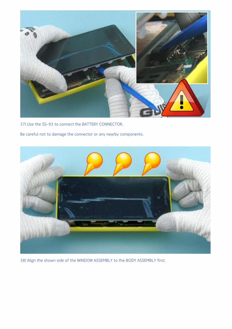
37) Use the SS-93 to connect the BATTERY CONNECTOR.
Be careful not to damage the connector or any nearby components.
38) Align the shown side of the WINDOW ASSEMBLY to the BODY ASSEMBLY first.
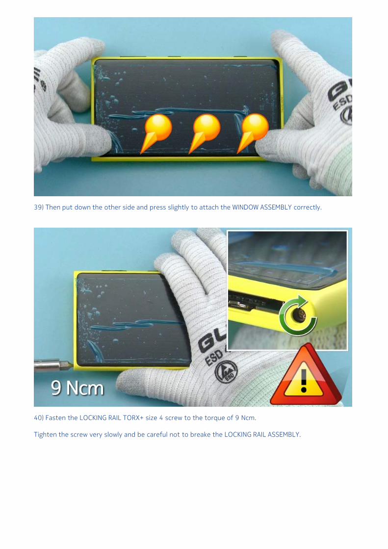
39) Then put down the other side and press slightly to attach the WINDOW ASSEMBLY correctly.
40) Fasten the LOCKING RAIL TORX+ size 4 screw to the torque of 9 Ncm.
Tighten the screw very slowly and be careful not to breake the LOCKING RAIL ASSEMBLY.
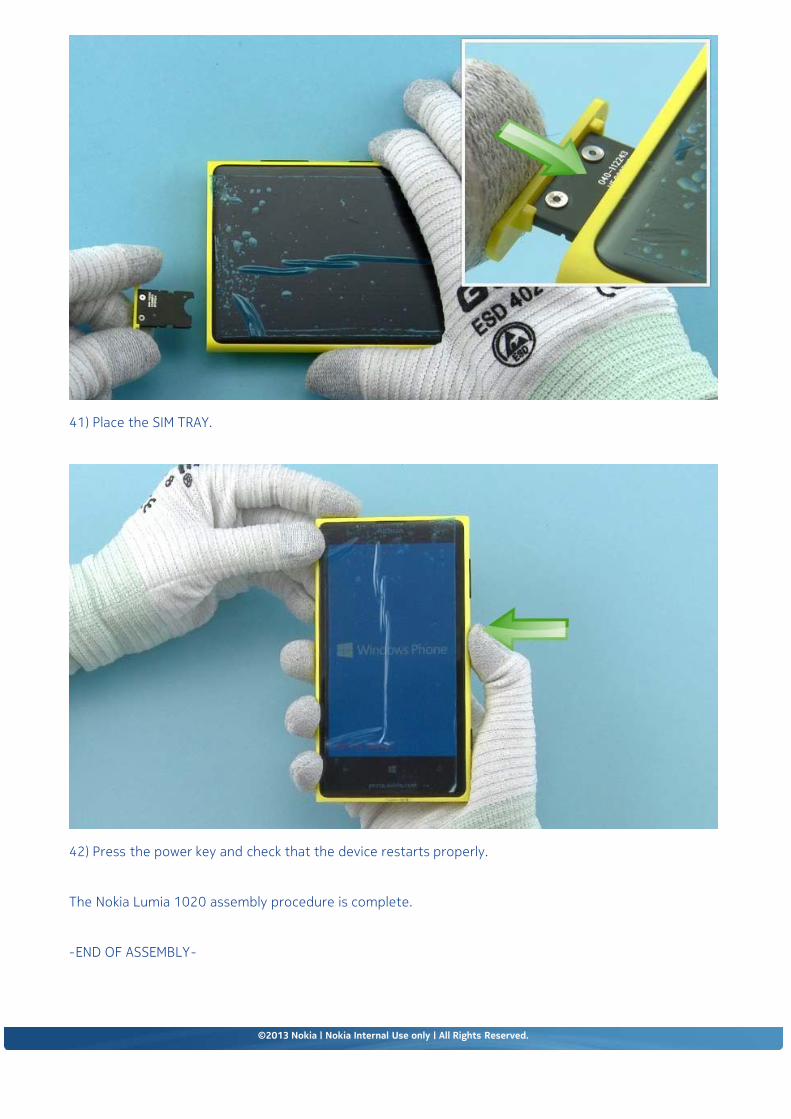
41) Place the SIM TRAY.
42) Press the power key and check that the device restarts properly.
The Nokia Lumia 1020 assembly procedure is complete.
-END OF ASSEMBLY-
©2013 Nokia | Nokia Internal Use only | All Rights Reserved.
Service Manual Level 1 and 2
Nokia Lumia 1020RM-877Version 2.0
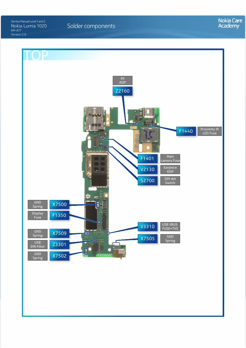
Solder components
F1350
F1401
F1440
S2700
V2130
V3310
X7500
X7502
X7505X7509
Z2160
Z3301
DisplayFuse
Proximity IRLED Fuse
Maincamera Fuse
USB VBUS FUSE+TVS
GNDSpring
EarpieceASIP
SIM detSwitch
GNDSpring
USBEMI Filter
GNDSpring
GNDSpring
AVASIP
TOP
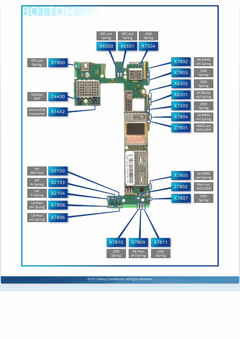
X6301
X6302
X6500 X6501
X7503
X7504
X7800 X7802
X7803
X7804
V2150
X1452
X2103
X2104
X7805
X7806
X7807X7808
X7809X7810 X7811
Z4400
Z7801
Z7802
Xenon B2BConnector
HB MIMOant Spring
GNDSpring
GNDSpring
BT/WLANant Spring
GNDSpring
LB MIMOant Spring
MIMO antDIPLEXER
LB MIMOant Spring
Main antDIPLEXER
GNDSpring
NFC antSpring
NFC antSpring
GNDSpring
IHFEMI Filter
IHFN-Spring
GPS antSpring
SidekeyASIP
IHFP-Spring
LB Mainant Spring
LB Mainant Spring
GNDSpring
HB Mainant Spring
GNDSpring
BOTTOM
©2013 Nokia | Confidential | All Rights Reserved.
Service Manual Level 1 and 2
Nokia Lumia 1020RM-877Version 2.0
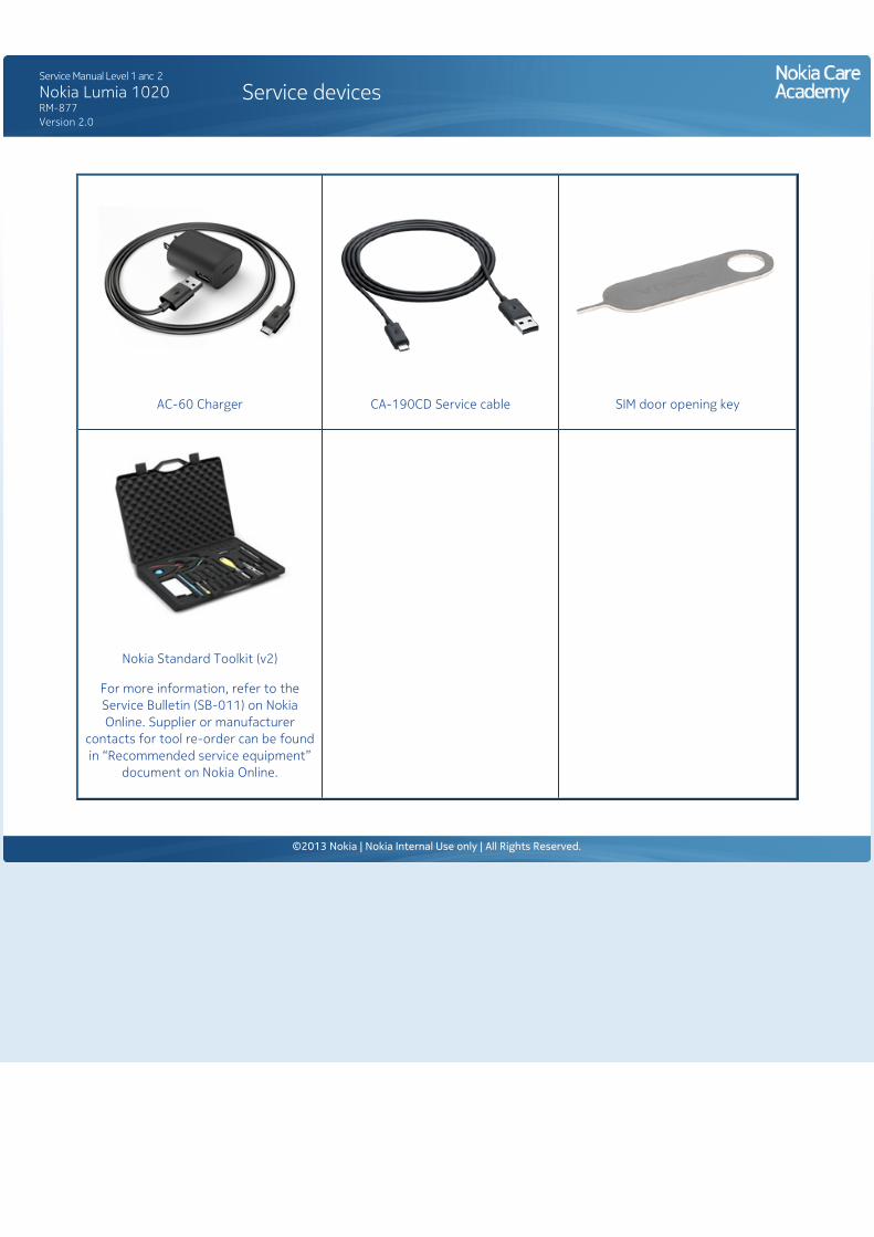
Service devices
AC-60 Charger CA-190CD Service cable SIM door opening key
Nokia Standard Toolkit (v2)
For more information, refer to the Service Bulletin (SB-011) on Nokia Online. Supplier or manufacturer
contacts for tool re-order can be found in “Recommended service equipment”
document on Nokia Online.
©2013 Nokia | Nokia Internal Use only | All Rights Reserved.
Service Manual Level 1 and 2
Nokia Lumia 1020RM-877Version 2.0
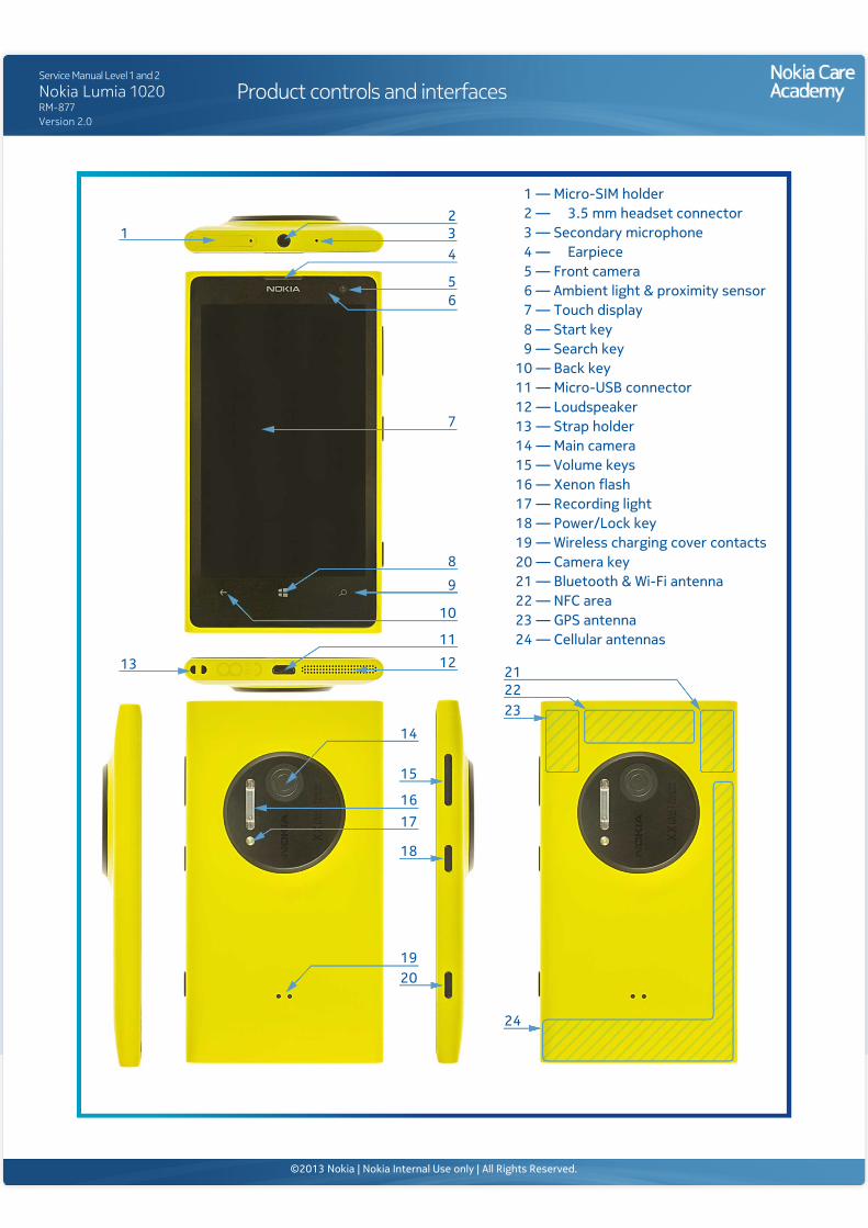
Product controls and interfaces
5
3
7
8
11
2
4
6
1
13
15
18
2019
16
9
12
10
212223
24
14
17
9 — Search key8 — Start key7 — Touch display6 — Ambient light & proximity sensor5 — Front camera4 — Earpiece3 — Secondary microphone2 — 3.5 mm headset connector1 — Micro-SIM holder
10 — Back key11 — Micro-USB connector12 — Loudspeaker13 — Strap holder14 — Main camera15 — Volume keys16 — Xenon flash17 — Recording light18 — Power/Lock key19 — Wireless charging cover contacts20 — Camera key21 — Bluetooth & Wi-Fi antenna22 — NFC area23 — GPS antenna24 — Cellular antennas
©2013 Nokia | Nokia Internal Use only | All Rights Reserved.
Service Manual Level 1 and 2
Nokia Lumia 1020RM-877Version 2.0
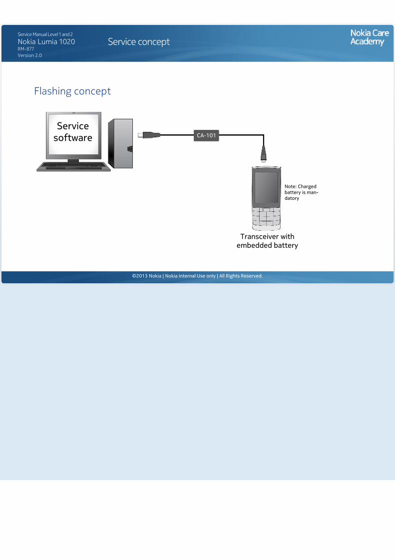
Service concept
Flashing concept
Note: Charged battery is man-datory
Transceiver with embedded battery
Service software CA-101
©2013 Nokia | Nokia Internal Use only | All Rights Reserved.
Service Manual Level 1 and 2
Nokia Lumia 1020RM-877Version 2.0
Phone reset
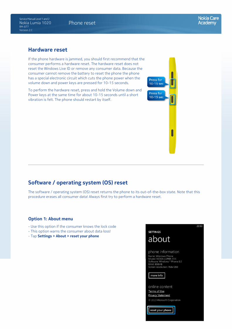
Hardware resetIf the phone hardware is jammed, you should first recommend that the consumer performs a hardware reset. The hardware reset does not reset the Windows Live ID or remove any consumer data. Because the consumer cannot remove the battery to reset the phone the phone has a special electronic circuit which cuts the phone power when the volume down and power keys are pressed for 10-15 seconds.
To perform the hardware reset, press and hold the Volume down and Power keys at the same time for about 10-15 seconds until a short vibration is felt. The phone should restart by itself.
Software / operating system (OS) resetThe software / operating system (OS) reset returns the phone to its out-of-the-box state. Note that this procedure erases all consumer data! Always first try to perform a hardware reset.
Option 1: About menu- Use this option if the consumer knows the lock code - This option warns the consumer about data loss! - Tap Settings > About > reset your phone
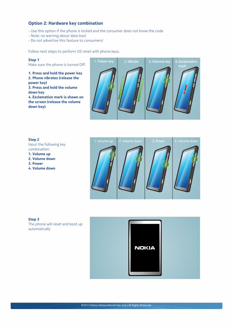
Option 2: Hardware key combination- Use this option if the phone is locked and the consumer does not know the code- Note: no warning about data loss!- Do not advertise this feature to consumers!
Follow next steps to perform OS reset with phone keys.
Step 1Make sure the phone is turned Off.
1. Press and hold the power key2. Phone vibrates (release the power key)3. Press and hold the volume down key4. Exclamation mark is shown on the screen (release the volume down key)
Step 2Input the following key combination:1. Volume up2. Volume down3. Power4. Volume down
Step 3The phone will reset and boot up automatically
©2013 Nokia | Nokia Internal Use only | All Rights Reserved.
Service Manual Level 1 and 2
Nokia Lumia 1020RM-877Version 2.0
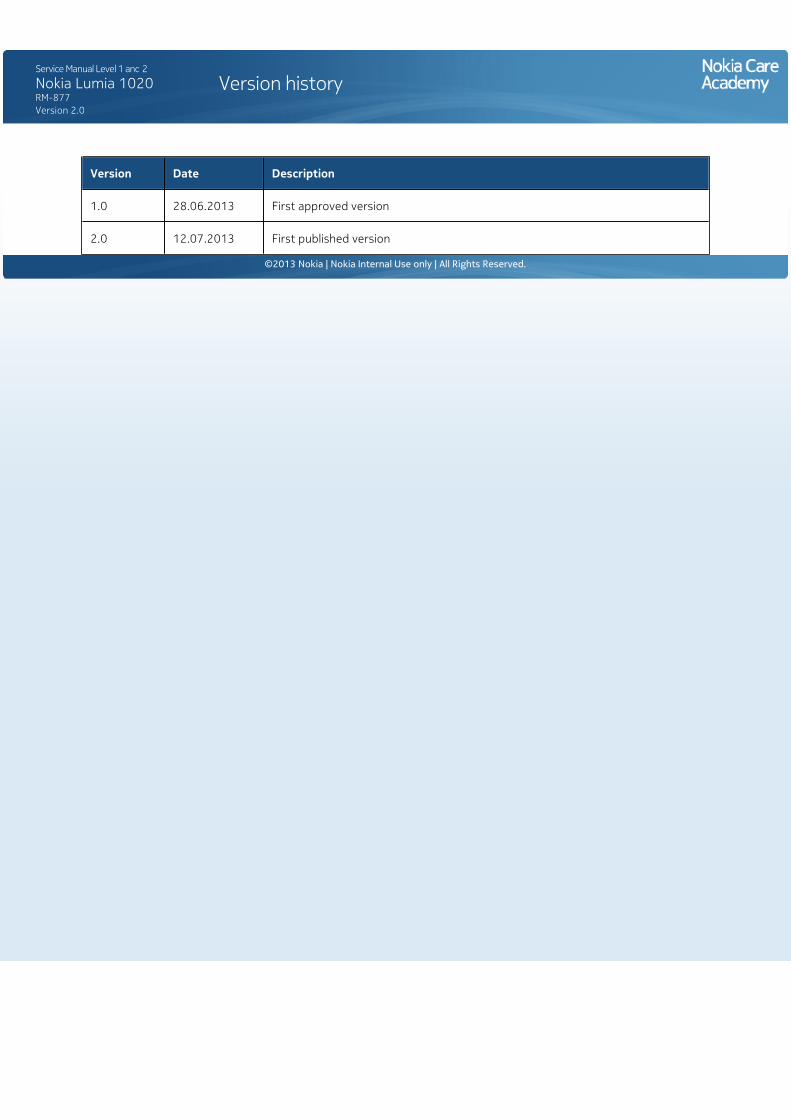
Version history
Version Date Description
1.0 28.06.2013 First approved version
2.0 12.07.2013 First published version
©2013 Nokia | Nokia Internal Use only | All Rights Reserved.