Embed Size (px)
DESCRIPTION
GPRS 2G
Citation preview

1 (53)
BSSPAR
GPRS & EGPRS (EDGE) Training Document
2 (53)
The information in this document is subject to change without notice and describes only the product defined in the introduction of this documentation. This document is intended for the use of Nokia Networks' customers only for the purposes of the agreement under which the document is submitted, and no part of it may be reproduced or transmitted in any form or means without the prior written permission of Nokia Networks. The document has been prepared to be used by professional and properly trained personnel, and the customer assumes full responsibility when using it. Nokia Networks welcomes customer comments as part of the process of continuous development and improvement of the documentation.
The information or statements given in this document concerning the suitability, capacity, or performance of the mentioned hardware or software products cannot be considered binding but shall be defined in the agreement made between Nokia Networks and the customer. However, Nokia Networks has made all reasonable efforts to ensure that the instructions contained in the document are adequate and free of material errors and omissions. Nokia Networks will, if necessary, explain issues which may not be covered by the document.
Nokia Networks' liability for any errors in the document is limited to the documentary correction of errors. Nokia Networks WILL NOT BE RESPONSIBLE IN ANY EVENT FOR ERRORS IN THIS DOCUMENT OR FOR ANY DAMAGES, INCIDENTAL OR CONSEQUENTIAL (INCLUDING MONETARY LOSSES), that might arise from the use of this document or the information in it.
This document and the product it describes are considered protected by copyright according to the applicable laws.
NOKIA logo is a registered trademark of Nokia Corporation.
Other product names mentioned in this document may be trademarks of their respective companies, and they are mentioned for identification purposes only.
Copyright © Nokia Oy 2004. All rights reserved.

3 (53)
Contents
1. Module Objectives ................................. ................................... 5
2. Introduction....................................... ........................................ 6 2.1. GPRS network architecture ........................................................ 6 2.2. EDGE (Enhanced Data rates for Global Evolution) ..................... 6 2.3. GPRS CSs and EGPRS MCSs ................................................... 7 2.4. 8-PSK ......................................................................................... 8 2.5. Mobile station capabilities ........................................................... 9
3. GPRS protocols .................................... .................................. 10 3.1. GPRS interfaces ....................................................................... 10 3.1.1. overview ................................................................................... 10 3.1.2. SGSN protocols ........................................................................ 11 3.1.2.1. Subnetwork Dependent Convergence Protocol (SNDCP) ......... 11 3.1.2.2. Logical Link Control(LLC) ......................................................... 11 3.1.2.3. Base Station Subsystem GPRS Protocol (BSSGP) .................. 11 3.1.3. (E)GPRS Mobility Management ................................................ 12 3.1.3.1. Concept of Routing Area .......................................................... 12 3.1.3.2. Mobility Management States ..................................................... 13 3.1.3.2.1. Idle State .................................................................................. 14 3.1.3.2.2. Standby State ........................................................................... 14 3.1.3.2.3. Ready State .............................................................................. 14 3.1.3.3. SGSN parameters related with states ....................................... 14 3.2. GPRS Procedures .................................................................... 15 3.2.1. GPRS Attach and Detach ......................................................... 15 3.2.2. PDP Context Functions and Addresses .................................... 16 3.2.2.1. PDP Context Activation ............................................................ 16 3.2.2.2. PDP Context Deactivation ........................................................ 17 3.2.3. Radio Link Control/ Medium Access Control (RLC/MAC) .......... 17 3.2.3.1. Radio Link Control (RLC) .......................................................... 17 3.2.3.2. Medium Access Control (MAC) ................................................. 18 3.2.3.3. Definition of a TBF .................................................................... 18 3.2.3.4. GPRS/E-GPRS RLC/MAC Block Structure ............................... 18 3.2.3.5. RR states .................................................................................. 19
4. Radio Resource Management ......................... ....................... 20 4.1. Enable GPRS ........................................................................... 20 4.3. Territory management .............................................................. 21 4.4. GPRS upgrades/downgrades ................................................... 23 4.5. GPRS Multiframes .................................................................... 24 4.6. Channel allocation .................................................................... 25 4.7. Logical channels for GPRS ....................................................... 26 4.8. Support of PCCCH, PBCCH ..................................................... 27

4 (53)
4.8.1. Configuration of PBCCH ........................................................... 27 4.8.2. Advantages of PBCCH ............................................................. 27 4.8.3. PBCCH/PCCCH Parameters .................................................... 28 4.8.3.1. in DL ......................................................................................... 28 4.8.3.2. in UL ......................................................................................... 29 4.9. C31, C32 .................................................................................. 29 4.10. Operation of an TBF ................................................................. 33 4.11. .Priority Class based QoS ......................................................... 35 4.12. GPRS Link Adaptation parameters ........................................... 38 4.13. EGPRS Link Adaptation parameters ......................................... 39 4.14. GPRS Power control ................................................................. 41
5. EDGE Dynamic A-bis Pool (EDAP)Creation Parameters ............................. 45
5.1. The concept .............................................................................. 45
6. Interworking with other features................... ......................... 49 6.1. Allocation of speech calls and GPR S ....................................... 49 6.2. MultiBCF/BCCH features .......................................................... 49 6.3. General note ............................................................................. 50
7. Appendix .......................................... ....................................... 52
5 (53)
1. Module Objectives
At the end of the module, the participant should be able to:
-List the parameters that are used for (E)GPRS radio timeslot (RTSL) classification
-Explain the purpose of the C31 and C32 criteria in (E)GPRS
-Discuss the implementation of priority class based QoS in (E)GPRS
-Describe the Dynamic A-bis allocation in BSS10.5
-State the interworking with other features

6 (53)
2. Introduction
2.1. GPRS network architecture
4 BSS´PAR-GPRS & EGPRS/© NOKIA
Hardware and Software Upgrades from GSM to GPRS
GPRS Core Network Elements
MSC
ISDN/PSTNNetwork
EIR
HLR/AuC
SMSC
BSCBTS
Um
Internet or Corporate
LAN
GPRS CoreNetwork
GPRS capable terminal
GSM compatibleHW and SW Upgrade in BSC (S9+PCU)
SW Upgrade in BTS
SW Upgrade in MSC/VLR and HLR NMS Upgrade to T12
New Services (APNs, WAP)
GPRS & EGPRS
Figure 1. GPRS network
GPRS is meant to serve bursty data transmission and provides higher speed in comparison to GSM. GPRS is built on top of the existing GSM network by means of HW and SW upgrade. The first Nokia Release supporting GPRS is S9.
A view of the network elements when GPRS is introduced into an existing GSM network can be found above.
The Hardware needed for GPRS in the BSS are the PCU (1or 2 per BCSU) and the connection towards the SGSN (Gb functionality)
2.2. EDGE (Enhanced Data rates for Global Evolution )
EDGE allows the introduction of new services based on GPRS – EGPRS (EDGE-GPRS). It can be seen as GSM enhancement. Flexible data capacity can be deployed where the demand is. New attractive services can be offered to end-users.

7 (53)
The introduction of EDGE in a GPRS network requires EDGE capable TRXs (that are downward compatible, they support EDGE, GPRS and GSM CS traffic, they are available for Ultra- and MetroSite) and Software (in Nokia the first release is S10 or 10.5).
2.3. GPRS CSs and EGPRS MCSs
5 BSS´PAR-GPRS & EGPRS/© NOKIA
GPRS CS and EDGE MCS
Coding Scheme
Modu-lation
User data rate (kbit/s)
Code rate
Useful bits
CS-1 GMSK 9.05 0.5 181
CS-2 GMSK 13.4 About 2/3
268
CS-3 GMSK 15.6 About 3/4
312
CS-4 GMSK 21.4 1.00 428
GPRS Coding Schemes
GPRS & EGPRS
Coding Scheme
Modu-lation
User data rate (kbit/s)
Useful bits
Family
MCS-1 GMSK 8.8 176 C
MCS-2 GMSK 11.2 224 B
MCS-3 GMSK 13.6 296 A (padding)
14.8 272+24
MCS-4 GMSK 17.6 352 C
MCS-5 8PSK 22.4 448 B
MCS-6 8PSK 27.2 592 A (padding)
29.6 544+48
MCS-7 8PSK 44.8 2*448 B
MCS-8 8PSK 54.4 2*544 A
MCS-9 8PSK 59.2 2*592 A
EDGE Modulation and Coding Schemes MCS
Figure 2. Coding schemes (CS) and Modulation and Coding Schemes (MCS)
One big advantage of GPRS and EDGE is the increased throughput compared with GSM. This is achieved by reducing the amount of error correction and for EDGE a new Modulation is introduced (8-PSK, 8-Phase Shift Keying).
Four Coding Schemes (CS 1-4) are defined for GPRS, nine Modulation and Coding Schemes (MCS 1-9) are defined for EGPRS.
For RLC Acknowledged mode not correctly received blocks have to be retransmitted. For GPRS the same CS has to be used, for EDGE the MCS may change within one family what may require adaptations (padding, adding of dummy bits).
With S11 Nokia supports GPRS CS 1 and 2 and all MCSs for EGPRS.
The PCU commands the CS/MCS that is used for one MS with the help of parameters and the quality of the radio link. During one data transfer the system may switch between the different types of encoding. The encoding may vary on a block by block basis. This is called Link adaptation (LA).

8 (53)
2.4. 8-PSK
6 BSS´PAR-GPRS & EGPRS/© NOKIA
(0,0,1)
(1,0,1)
(0,0,0) (0,1,0)
(0,1,1)
(1,1,1)
(1,1,0)
(1,0,0)
8-PSK Modulation
EDGE GSM + EDGE
Modulation 8-PSK, 3bit/sym GMSK, 1 bit/symSymbol rate 270.833 ksps 270.833 kspsBits/burst 348 bits(=2x3x58) 114 bits(=2x57)Gross rate/time slot 69.6 kbps 22.8 kbps
• 8-PSK (Phase Shift Keying) is the new modulation added in EDGE
• 3 bits per symbol
• 22.5° offset to avoid origin crossing(called 3Π/8-8-PSK)
• Symbol rate and burst length identical to those of GMSK
• high requirements for linearity of the power amplifier
• Because of amplifier non-linearities, a 2-4 dB power decrease (back-off)
3ππππ/8
GPRS & EGPRS
Figure 3. 8-Phase Shift Keying
5 out of the 9 MCSs defined for EDGE use 8-PSK. The new Modulation works within the same frequency band of GSM. But within the time required to send one bit with GMSK (Gaussian Minimum Shift Keying, the modulation used in GSM, MCS 1-4 and GPRS), 3 bits can be sent using 8-PSK (the duration of a symbol is the same). So the possible throughput is about 3 times that of GPRS. 8- PSK is more sensible. So it is only suitable for good radio conditions.
3pi/8 rotation of the symbols is done to avoid zero crossings of the amplitude.
More details about Modulation can be found in the EDGERPL course.

9 (53)
2.5. Mobile station capabilities
8 BSS´PAR-GPRS & EGPRS/© NOKIA
GPRS Multislot Classes
Type 1
Multislot Classes 1-12- Max 4 DL or 4 UL TSL (not at same time)- Up to 5 TSL shared between UL and DL- Minimum 1 TSL for F Change- 2-4 TSL F Change used when idle measurements
required
Multislot Classes 19-29- Max 8 downlink or 8 uplink
(not required at same time)- 0-3 TSL F Change
Type 2
Multislot Classes 13-18- simultaneous receive & transmit- max 8 downlink and 8 uplink
(Not available yet, difficult RF design)
DL
UL
DL
UL
1 TSL for Frequency Change
1 TSL for Measurement
DL
UL
GPRS & EGPRS
Figure 4. Multislot capabilities
MS capabilities differ in terms of band support, multislot capabilities and there may be as well MSs that support 8-PSK only in DL. The PCU that is responsible for allocating resources for a certain MS has to know:
What are the supported frequency bands?
What is the Multislot class of that MS? (how many RTSL can be given to that MS)
Does the MS support EDGE? And if, is 8-PSK supported in UL as well?

10 (53)
3. GPRS protocols
3.1. GPRS interfaces
3.1.1. overview
10 BSS´PAR-GPRS & EGPRS/© NOKIA
GPRS Interfaces
Gf
D
Gi
C
E
Gp
Gs
Signaling and Data Transfer InterfaceSignaling Interface
MSC/VLR
TE BSS TEPDNR Um
Gr
HLR
Other PLMNGGSN
Gd
SM-SCSMS-GMSCSMS-IWMSC
EIR
IP BB
DNS CG LIG
Gn Gn
GcA
GbMT SGSN
Gn
Gn Gn
DNS
DHCP
APNFW
GPRS & EGPRS
GGSN
Figure 5. GPRS interfaces
The SGSN is a main component of the GPRS network, which handles e.g. the mobility management and authentication. The SGSN is connected to the BSC via the Gb interface. It is the service access point to the GPRS network for the GPRS MS.

11 (53)
3.1.2. SGSN protocols
11 BSS´PAR-GPRS & EGPRS/© NOKIA
SNDCP: Subnetwork Dependent Convergence ProtocolLLC: Logical Link ControlRLC: Radio Link ControlMAC: Medium Access Control
BSSGP: BSS GPRS ProtocolFR: Frame Relay
GTP: GPRS Tunneling ProtocolUDP: User Datagram Protocol
TCP: Transmission Control ProtocolIP: Internet Protocol
NS: Network Service
BSSUmMS SGSNGb Gn GGSN
GSM RF L1 L1 L1 L1GSM RF
MAC
RLC
LLC
SNDCP
IP
Application
MAC
RLC
FR/NS
BSSGPRelay
FR/NS
BSSGP
LLC
SNDCP
L2 L2
IP IP
UDP/TCP UDP/TCP
GTP GTP
IP
Relay
GPRS & EGPRS
(E)GPRS Protocols for user data
Different in
EGPRS and
GPRS
Figure 6. (E)GPRS Transmission Plane
3.1.2.1. Subnetwork Dependent Convergence Protocol (SNDCP)
The SGSN converts the IP protocol used in the backbone network to the SNDCP protocol used between the SGSN and the MS. ): This transmission functionality maps network-level characteristics onto the characteristics of the underlying network. This layer handles the compression of data.
3.1.2.2. Logical Link Control(LLC)
At Layer 3 of the OSI model the LLC layer offers a secure, ciphered and reliable logical link between the MS and the SGSN (Serving GPRS Support Node). It is independent of the lower layer. This allows the introduction of alternative GPRS radio solutions with minimum changes to the NSS. The LLC layer can be acknowledged and not acknowledged. LLC provides different SAPIs (Service Access Point Identifier) for SMS, GMM and user data with different quality of service.
LLC frames have a flexible length and they are sent towards the PCU. In DL if the LLC frames can not be sent towards the MS, the PCU may discard the frames. It will inform then the SGSN.
3.1.2.3. Base Station Subsystem GPRS Protocol (BSSG P)
The BSSGP transfers the LLC frames between one PCU and one SGSN. In DL the PCU is informed about QoS parameters, the cell (BVCI, BSSGP Virtual Connection Identifier) and

12 (53)
the receiver of the LLC frame (TLLI, Temporary Logical Link Identifier). Error correction is not performed. In DL Flow control for each cell and MS is executed. So overflow (resulting in discarding of LLC Frames in PCU) can be avoided. No error correction is performed on this layer.
3.1.3. (E)GPRS Mobility Management
The SGSN takes care about the GMM. An MS registers in an SGSN. The SGSN takes care of its mobility management. When the MS wants to send (or receive) data to (from) external networks the SGSN relays the data between the SGSN and relevant GGSN (and vice versa).
3.1.3.1. Concept of Routing Area
14 BSS´PAR-GPRS & EGPRS/© NOKIA
Routing Areas
• Routing Areas RA are used for GPRS Mobility Management• A RA is a subset of one, and only one, Location Area (LA).
• A RA is served by only one SGSN.• For simplicity, the LA and RA can be the same.
Location Area (LA)
Routing Area (RA)
SGSN
MSC/VLR
GS Interface
GPRS & EGPRS
Figure 7. Routing Areas

13 (53)
One or more cells form a Routing Area (RA), which is a subset of one Location Area (LA). Every RA is served by only one SGSN but one SGSN may handle several RAs. The tracking of the location of an MS depends on the mobility management state. When an MS is in a STANDBY state, the location of the MS is known on a RA level. When the MS is in a READY state, the location of the MS is known on a cell level. Figure 8. shows the different mobility management states and transitions between them. The Routing Area Identy (RAI) identifies a RA.
RAI = MCC (Mobile Country Code). + MNC(Mobile Netwo rk Code) + LAI (Location Area Identity) + RAC
Routing Area Code(RAC)(SEG)(0…255)(255) is set in the Database for each cell. One RA is served by one SGSN. Before GPRS is enabled the RA has to be configured. The network plan should be considered because the Ras are as well configured in the SGSN. For the size of a RA one should consider the paging capacity (LAPD load, Channel configuration)
3.1.3.2. Mobility Management States
GPRS Mobility Management States
Idle
Standby
Ready
PacketTX/RXSTANDBY
Timer Expiry
GPRSAttach�/ Detach
READYTimer Expiry
MS location known onRA level. MS can be paged
MS location not known. Subscriber is notreachable by the GPRS NW.
MS location known to cell level.MS is transmitting or has just been transmitting.
GPRS & EGPRS
Figure 9. GMM states
Three GPRS mobility management states are defined. The IDLE state is used when the subscriber (MS) is passive (not GPRS attached). The STANDBY state is used when the subscriber has ended an active phase. An MS is in an active phase (READY state) when it is transmitting or has just been transmitting. The change between the states happens upon activity or when a timer expires.

14 (53)
3.1.3.2.1. Idle State
The subscriber is not reachable by the GPRS network. The MS is only capable of receiving PTM-M data (GPRS Phase2). The network elements hold no valid context for the subscriber and the subscriber is not attached to the mobility management. In order to change state, the MS has to perform a GPRS Attach procedure.
3.1.3.2.2. Standby State
The subscriber is attached to the mobility management and the location of an MS is known on a routing area level. The MS is capable of receiving PTM data (GPRS Phase2) and pages for PTP data. The network holds a valid mobility management context for the subscriber. If the MS sends data, the MS moves to READY state. The MS or the network can initiate the GPRS Detach procedure to move to IDLE state. After expiry of the MS reachable timer, the network can detach the MS. The MS can use the Discontinuous Reception (DRX) to save the battery.
3.1.3.2.3. Ready State
The subscriber is attached to the mobility management and the location of an MS is known on a cell level. The MS is capable of receiving PTM (Point to Multi point) and PTP (point to point) data. The SGSN can send data to the MS without paging at any time and the MS can send data to the SGSN at any time. The network holds a valid mobility management context for the subscriber. If the READY timer expires, the MS moves to STANDBY state. If the MS performs a GPRS Detach procedure, the MS moves to IDLE state and the mobility management context is removed. An MS in READY state does not necessarily have radio resources reserved. The MS can use the DRX to save the battery.
3.1.3.3. SGSN parameters related with states
(periodic RA update timer) 00 – (02…62) sec in steps of 2 sec (min)–(sec)
(01…31) – 00 min in steps of 1 min (min)–(sec)
(36…184) – 00 min in steps of 6 min (min)-(sec)
(00…00) – no periodic RA update
54 min
(Ready state timer) 00 – (02…62) sec in steps of 2 sec (min)–(sec)
(01…31) – 00 min in steps of 1 min (min)–(sec)
(36…184) – 00 min in steps of 6 min (min)-(sec)
(00…00) – no ready state timer
(00…01) – ready state timer is deactivated, MS remains in ready state.
44 s
(force to standby, FTS) Y … Force to standby in use N

15 (53)
N … Force to standby not in use
(MS reachable timer, MSRT) 2…59 – 0…186 (min–sec)
(00-00) no MS reachable counter
60 min
3.2. GPRS Procedures
GSM RF
MAC
RLC
LLC
SM
GSM RF
MAC
GSM RF L1
GMM
MAC
RLC
FR/NS
BSSGPRelay
L1
FR/NS
BSSGP
LLC
SM
GPRS signallingGPRS & EGPRS
BSSUmMS Gb SGSN
GMM
GMM: GPRS Attach/DetachRA updateCell Update...
SM: PDP context activationPDP context deactivation...
000100110101011110011011
SAPI ServiceGMM, SMUser data 1User data 2SMSUser data 3User data 4
SAP NameGMMQoS1QoS2SMSQoS3QoS4
0001
0011
0101
0111
1001
1011In LLC header
Figure 10. Signalling Plane
3.2.1. GPRS Attach and Detach
GPRS Attach and GPRS Detach are mobility management functions to establish and to terminate a connection with the GPRS network. With the GPRS Attach the mobile moves to READY state and the mobility management context is established, the MS is authenticated, the ciphering key is generated, a ciphered link established and the MS is allocated a Temporary Logical Link Identity (TLLI). The SGSN gets the subscriber information from the HLR. After a GPRS Attach, the SGSN tracks the location of the MS. The MS can send and receive SMS, but no other data. To transfer other data it has to first activate a PDP context.

16 (53)
The GPRS Detach moves the MS to IDLE state and the mobility management context is removed. The MS can be detached from the GPRS also implicitly when the mobile reachable timer expires. The GPRS Detach is normally generated by the MS, but can also be generated by the network.
3.2.2. PDP Context Functions and Addresses
15 BSS´PAR-GPRS & EGPRS/© NOKIA
INACTIVEstate
ACTIVEstate
De-activation PDP context /GPRS detach
expiry STANDBY timerActivation
PDP context
• PDP not activated
• no Routing-contextfor MS, SGSN & GGSN
• no data transmission possible !
Transition to „Active“ Stateonly if MM-context exists
( MS & SGSN: STANDBY / READY)
• Routing contextfor MS, SGSN & GGSN
• Data transmission possible !
GPRS PDP StatesGPRS & EGPRS
Figure 11. PDP states
One PDP context includes one address (usually a dynamic IP address) and one set of QoS attributes. Several PDP contexts may be activated simultaneous. When the subscriber has finished the use of the activated addresses, they have to be deactivated. As long as PDPs are activated the MS has to be in STANDBY or READY state. Return to GMM ‘idle’ automatically deactivates all active PDPs.
3.2.2.1. PDP Context Activation
The PDP context activation can be initiated by the MS or by the network. The Activate PDP Context Request is sent to the SGSN when a certain address requires activation. As an option, the request can also be made by the GGSN, if packets are received for an address without active context and the MS is GPRS Attached. The request contains parameters for the context, like the TLLI, the protocol type, the address type, QoS, requested GGSN, etc.

17 (53)
3.2.2.2. PDP Context Deactivation
The PDP context can be deactivated by the MS or by the network. Every address can be deactivated separately, but when the GPRS Detach is performed, the network will automatically deactivate all activated PDP Contexts..
3.2.3. Radio Link Control/ Medium Access Control (R LC/MAC)
16 BSS´PAR-GPRS & EGPRS/© NOKIA
EGPRS RLC/MAC Header for Data Block
Bit8 7 6 5 4 3 2 1 Octet
TFI RRBP ES/P USF 1BSN1 PR TFI 2
BSN1 3BSN2 BSN1 4
CPS BSN2 5
B it8 7 6 5 4 3 2 1 O c te t
T F I C o u n td o w n V a lu e S I R 1B S N 1 T F I 2
B S N 2 B S N 1 3B S N 2 4
S p a re P I R S B C P S 5S p a re 6
Downlink:
Uplink:
Ref: TS 04.60
• Three header types for EGPRS RLC/MAC data block
• Example: Header type 1 (header for MCS-7, MCS-8 and MCS-9)
GPRS & EGPRS
Figure 12. Example of a RLC/MAC header
Radio Link Control (RLC) and Medium Access Control (MAC) are on top of the GSM RF: the former offers a reliable radio link (may work in Ack or Nack mode) to the upper layers and the latter handles the channel allocation and the multiplexing.
EGPRS provides enhancements for the RLC/MAC Protocol. New header and Control messages are defined for EGPRS on this layer.
3.2.3.1. Radio Link Control (RLC)
The RLC function defines the procedures for segmentation and re-assembly of LLC PDU into RLC/MAC blocks and in RLC acknowledged mode of operation the Backward Error Correction (BEC) procedures enabling the selective retransmission of unsuccessfully delivered RLC/MAC blocks (ARP- Automated Repeat Request)
The RLC function provides also link adaptation. In EGPRS in RLC acknowledged mode of operation, the RLC function may provide Incremental Redundancy (IR).
The RLC function is responsible for:

18 (53)
Interface primitives allowing the transfer of Logical Link Control layer PDU (LLC PDU) between the LLC layer and the MAC function.
Segmentation of LLC PDU into RLC data blocks and re-assembly of RLC data blocks into LLC PDU.
Segmentation of RLC/MAC control messages into RLC/MAC control blocks and re-assembly of RLC/MAC control messages from RLC/MAC control blocks.
Backward Error Correction (BEC) procedures enabling the selective retransmission of RLC data blocks.
3.2.3.2. Medium Access Control (MAC)
The MAC protocol allows that a physical channel is shared between many MSs (up to 16 in DL and UL, for UL the maximum is 7). Furthermore it allows one MS to use several physical channels in parallel. It is responsible for queuing and scheduling of access attempts.The MAC protocol provides Temporary Block Flows (TBF) that allow the point-to-point, unidirectional transfer of signalling and user data within a cell between the network and a MS. Moreover, the Medium Access Control include the procedures for reception of PBCCH and PCCCH, which permits autonomous cell reselection performed by the mobile station (see 3GPP TS 05.08)
3.2.3.3. Definition of a TBF
A TBF is an allocated radio resource on one or more PDCH and comprise a number of RLC/MAC blocks carrying one or more LLC PDU. A TBF to/from the MS is maintained only for the duration of the data transfer.
Each TBF is assigned a Temporary Flow Identity (TFI) by the network. The TFI is assigned in a resource assignment message and is part of the first octet of the RLC/ MAC block. The TFI allows several MSs to share one RTSL.
The TBF is identified by the TFI together with:
The direction (UL or DL) in which the RLC data block is sent
The direction (UL or DL) in which the RLC/MAC control message is sent and the message type.
The TBF can be initiated by either the MS or the network.
3.2.3.4. GPRS/E-GPRS RLC/MAC Block Structure
For data transfer and transfer of control messages different RLC/MAC blocks are specified in UL and DL direction. One RLC/MAC block is always carried on 4 bursts.
In total 6 different types of RLC/MAC blocks are used:
DL RLC/MAC control blocks (used for GPRS and E-GPRS)
UL RLC/MAC control blocks (used for GPRS and E-GPRS)
GPRS DL RLC/MAC data blocks
GPRS UL RLC/MAC data blocks

19 (53)
E-GPRS DL RLC/MAC data blocks
E-GPRS UL RLC/MAC data blocks TS 05.08)
3.2.3.5. RR states
Radio Resource (RR) management procedures are characterised by two different RR operating modes: Packet Idle Mode
and Packet Transfer Mode.
In packet idle mode no Temporary Block Flow exists. Upper layers can require the transfer of a LLC PDU which, implicitly, may trigger the establishment of TBF and transition to packet transfer mode.
In packet idle mode, the MS listens to the BCCH and to the relevant paging sub-channels. Packet transfer mode
In packet transfer mode , the mobile station is allocated radio resource providing a Temporary Block Flow on one or more physical channels.
When selecting a new cell, mobile station leaves the packet transfer mode, enters the packet idle mode where it switches to the new cell, reads the system information and may then resume to packet transfer mode in the new cell. The interworking between Radio Resource operating modes and Mobility Management States is shown in the table.
Radio Resource
MS
Packet Transfer
Mode
Packet Idle
Mode
Packet Idle
Mode
Mobility Management
MS
Ready
Standby
Table Correspondence between RR operating modes and MM states
Each state is protected by a timer. The timers run in the MS and the network. Packet transfer mode is guarded by RLC protocol timers.

20 (53)
4. Radio Resource Management
4.1. Enable GPRS
GPRS is enabled in a BTS using GprsEnabled(GENA)(BTS)(Yes/No) .
GPRS is enabled in a TRX using
GprsEnabledTRX (GENA)(GTRX)(Yes/No)(No)
Adjacent GPRS enabled (AGENA)(Y;N)(N) is used to enable GPRS for adjacent cells.
4.2. Enable EDGE Talk Family BTS site can be upgraded to EDGE functionality by adding an Ultrasite EDGE BTS as an extension cabinet. Common BCF feature is required. The cabinets are synchronised and seen as one object (site) by OSS and BSC.
Because of the increased throughput on the Abis per RTSL it is not sensible to allocate fixed transmission capacity according to the highest possible throughput. In Nokia the solution is a pool of Abis Resources, that is shared among several TRXs, the EDGE Dynamic Abis Pool (EDAP) is required for EDGE. As a secondary requirement for the introduction of EGPRS more capacity is needed on Abis as well as on gb interface.
To enable EGPRS the BTS and all other BTSs of that segment have to be GPRS enabled (GENA=yes) and all TRXs of that BTS have to be EDGE capable. EGPRS is enabled in a BTS using
EGPRSenabled(EGENA)(BTS)(Yes/No)(No) .

21 (53)
4.3. Territory management
18 BSS´PAR-GPRS & EGPRS/© NOKIA
GPRS – GSM BoundaryGPRS & EGPRS
Figure 13. Nokias Territory method
A timeslot can be used for circuit switched (CS) traffic (then it is served by the BSC) or for packet switched (PS) traffic (then it is served by the Packet Control Unit (PCU) in the BSC). All full rate or dual rate traffic channels are capable of carrying PS traffic.
All timeslots in one BTS controlled by the PCU belong to the PS or GPRS territory, all other to the CS territory. The border between CS and PS territory moves dynamically, dependant on parameters set and on the required traffic.
Timeslots in the PS territory are classified into dedicated, default and additional TSL.
-Dedicated TSLs are reserved for GPRS traffic. They can not carry CS traffic!
dedicatedGPRScapacity (CDED)(BTS)(0..100%)(0%) is used to set the dedicated percentage of packet-switched RTSL. The capacity is given as a percentage of the total capacity of the BTS.
Any percentage is rounded down to the closest integer number of RTSL. Exception is a setting of a value between 0% and the percentage that corresponds to one RTSL. Here the value is rounded up to one RTSL. 1% means in all practical cases one RTSL. 1% and 20% for a 1 TRX BTS correspond to 1 RTSL.
-Default TSLs contain dedicated and shared TSLs. The shared TSLs can handle CS and PS traffic. When allowed by the CS traffic load the shared TSLs belong to the PS territory. That means the system may perform intra cell handovers to reallocate these TSLs to the GPRS territory. The system tries to keep this number of RTSLs free from CS load.

22 (53)
defaultGPRScapacity (CDEF)(BTS)(0..100%)(1%) defines the default packet-switched channels in a cell. It is used to set the percentage of available RTSL for GPRS capacity.
Additional TSL are dynamically taken for GPRS when required, that means there is a lot of GPRS traffic and low CS traffic. The activation happens load dependant, there is no parameter related with that (on all GPRS enabled TRXs). Allocated calls may be handed over to other RTSLs. Anyway it is possible to define a maximum size of the PS territory:
maxGPRScapacity (CMAX)(BTS)(0..100%)(100%) . The value has to be equal or bigger than CDEF parameter!
Please note that GPRS resources are not allocated t o a specific timeslot!! Channel Allocation for GPRS data uses a two phase access procedure in the BSC. First the BSC defines the GPRS territory. The best candidate is the TRX having the most idle successive resources. GPRS Territory is always allocated starting from RTSL 7 towards 0. A TRX containing permanent TCH/F time slots is preferred to one holding Dual Rate timeslots (of course GPRS has to be enabled for that TRX and that BTS). The Territory – if allowed by parameters may span of course several TRXs.
preferBCCHfreqGPRS(BFG)(BTS)(Yes/No)(no) defines a preference to the BCCH TRX for GPRS territory allocation.
19 BSS´PAR-GPRS & EGPRS/© NOKIA
Free Timeslots in CSW Territory
No. of TRXs / BTS Free TSLs (afterGPRS downgrade)
Free TSLs (afterGPRS upgrade)
Mean free TSL in CSW
1 1 1 12 1 2 1.53 1 2 1.54 2 3 2.55 2 4 36 2 4 37 2 4 38 3 5 49 3 5 410 3 6 4.511 3 6 4.512 3 6 4.5
CSW "Push"
Free TSL "Pull"- TSL must be free after GPRS upgrade
- Will upgrade after "Upgrade Guard Time"
GPRS & EGPRS
How many free timeslots are defined for different BTS configurations?
Figure 14. Free TSLs in the CS

23 (53)
20 BSS´PAR-GPRS & EGPRS/© NOKIA
• Circuit Switched traffic has priority outside dedicated territory
• GPRS dedicated time slots (% of total cell capacity) can be defined.
• Dedicated TSLs belong to Default TSLs
• Territories consists of consecutive timeslots
• GPRS can be set to favour the BCCH Transceiver -> minimum interference
BCCHTRX 1
TRX 2
TS Circuit Switched Territory
Circuit / Packet Switched Territory
Dedicated GPRS Capacity (%)
TS TS TS TS TS TS
TS TS TS TS TS TS TSTS
Default GPRS capacity threshold
GPRS Territory Parameters
Free time slots in Circuit Switched territory
Default GPRS Capacity (%)
Maximum GPRS Capacity (%)
Additional GPRS Capacity
GPRS & EGPRS
Figure 15. Territory parameters
4.4. GPRS upgrades/downgrades
terrUpdateGuardTimeGPRS (GTUGT)(BSC)(1..255)(5) defines the minimum time in seconds between territory updates. (GPRS upgrade or downgrade).
The system tries to keep some TSs in the CS territory free at the border to the GPRS territory. The idea is to avoid delays for CS requests or even blocking. This margin depends if an upgrade or downgrade is started. It is definable. The parameter Free TSL for CS downgrade (CSD)(BSC)(0-100%)(95%) defines a target probability of TCH availability after a downgrade. Free TSL for CS upgrade (CSU)(0-10s)(4s) defines the period following an upgrade during which the probability of a downgrade is less than 5%. Depending on the set parameter and on the number of TRXs in a BTS the system will calculate a number of TSs that is kept free. The number is defined with a look up table. With two TRXs and default values there is one TS after an downgrade and 2 TS after an upgrade kept free. This has to be considered for load calculations.
An upgrade is started by the BSC if
-GPRS is enabled
-number of TRXs or RTSLs is increased (unblock TRX or TS inside Territory) and there is an pending upgrade.

24 (53)
-circuit switched calls are released (intracell handovers may be performed to clean the resources besides the territory) and more TSs as the margin defined are free (and the need for an upgrade exists).
-An upgrade is requested by the PCU and resources are available
The PCU checks the need for upgrades when new TBFs are requested. Target is to give MSs as many TSs as they support and to have one active MS per timeslot. Additional TSs are just requested if there are more than 1.5 TBFs per TS or if MS would support more than the allocated number of TSs and the default GPRS territory is available (it is task of BSC to keep default territory free, if CS load allows it).
GPRS downgrades is started by the BSC if.
-GPRS is disabled
-TRXs or TSs carrying GPRS traffic are blocked
-CS load increases (or TSs carrying CS Traffic are blocked) and there are less than the defined margin of idle TCHs.
-PCU requests downgrades
The PCU will request a downgrade for additional TSs if there are less than 0.5 TBFs per TS.
4.5. GPRS Multiframes
21 BSS´PAR-GPRS & EGPRS/© NOKIA
GPRS Multiframe
B0 B1 B2 T B3 B4 B5 X B6 B7 B8 T B9 B10 B11 X
A physical channel allocated to carry packet logical channels is called a Packet
Data CHannel (PDCH). A PDCH only carries GPRS logical channels.
GPRS logical channels are dynamically mapped onto a 52 multiframe. It consists
out of 12 Radio blocks, 2 idle frames and 2 frames used for PTCCH
4 x TDMA Frames = 4 Bursts = 1 RLC/MAC block = 18.4 6 ms
0 7 0 7 0 7 0 7
52 TDMA Frames = 52 Bursts = 12 RLC/MAC blocks = 240 ms
X = Idle frameT = Frame used for PTCCHB0 - B11 = Radio blocks
GPRS & EGPRS
Figure 16. GPRS Multiframes

25 (53)
Timeslots in the GPRS Territory show a different multiframe structure as for CS traffic. In GSM 26 and 51 TDMA multiframes are defined. For GPRS it is a 52 TDMA multiframe. A timeslot carrying GPRS traffic is referred as PDCH (Packet Data Channel). 12 Radio blocks (RLC/MAC) can be found. Each Radio Block consists of 4 bursts, carrying GPRS traffic or signalling for one user. It has a duration of 20 ms. Different users can share one timeslot. Subsequent radio blocks may be allocated to different users (RTSL sharing will of course reducing the throughput for the users). The used CS (for EDGE MCS) may vary from block to block, TSs may even be shared between GPRS and EDGE MSs.
Between the Blocks there are control information (the PTCCH Packet Timing advance control channel) and idle frames. They are used by all the MSs that have allocated resources on that TS to measure neighbours respectively to keep control of the TA of these MSs.
4.6. Channel allocation
4.6.1. For GPRS
Principles: UL and DL are independent resources
RLC MAC limits the number of users to 7 UL and 16 (UL and DL)
Allocated RTSLs have to belong to one TRX
The RTSLs that give the max possible (priority based capacity) are preferred. MS capabilities are considered. The parameters
Maximum number of UL TBF(MNUL)(BSC)(1-7)(7)
Maximum number of DL TBF(MNDL)(BSC)(1-9)(9)
define how many users can share one RTSL on average. That means the system may temporarily more than the indicated value on one RTSL.
For UL resources the specifications define 3 Medium Access Modes:
Dynamic, extended dynamic, fixed allocation. Starting from the first release Nokia supports the dynamic allocation. So besides the TFI an USF (Uplink State Flag) for each assigned RTSL is required.
4.6.2. Interworking between GPRS and EDGE
Multiplexing of GPRS and EGPRS TBFs is possible. Because for DL TBFs an USF is required, and an GPRS MS is not enabled to read the USF on an 8-PSK burst, the system may be forced to use an reduced MCS for an DL TBF. This means multiplexing may reduce the potential throughput for the DL EGPRS user. The system tries to avoid this by allocating different RTSLs or even BTSs (with Multi BCF feature) to GPRS and EGPRS users.

26 (53)
4.7. Logical channels for GPRS
22 BSS´PAR-GPRS & EGPRS/© NOKIA
GPRS Logical ChannelsGPRS & EGPRS
Figure 17. GPRS Logical channels
GPRS introduces several new logical channels. Not all of them are mandatory, the PNCH is currently not supported. To support PBCCH is an option. PCCCs depend on the PBCCH.
PBCCH The Packet Broadcast Control Channel is a downlink only channel for broadcasting packet data (GPRS) specific system information messages to all GPRS enabled MS in a cell. If the PBCCH is not allocated, the packet data specific SI is broadcast on the BCCH.
PCCCH The Packet Common Control Channel (PCCCH) consists of logical channels used for common control signalling for packet data. There are four types of PCCCH: PRACH, PAGCH, PPCH and PNCH.
PRACH The Packet Random Access Channel is an uplink only channel, which the MSs use for uplink traffic channel request and for obtaining the timing advance.
PPCH The Packet Paging Channel is a downlink only paging channel used to page the MS prior to downlink packet transfer. The PPCH can be used for CS & PS paging.
PAGCH The Packet Access Grant Channel is a downlink only channel used for resource assignment during the packet transfer establishment phase.
PNCH The Packet Notification Channel (only in GPRS Phase2) is a downlink only channel used for the PTM-M notifications to a group of MSs before PTM-M packet transfer.
PDTCH The Packet Data Traffic Channel is for GPRS packet data transfer. A PDTCH corresponds to the resource allocated to a single MS on one physical channel for user data

27 (53)
transmission. In multislot operation, one MS may use multiple PDTCHs in parallel for individual packet transfer. PDTCH are uni-directional.
PACCH The Packet Associated Control Channel (bi-directional) is a signalling channel dedicated for a certain MS. The signalling information could include acknowledgements, power control, resource assignments or reassignment messages.
PTCCH The Packet Timing advance Control Channel is used in the uplink direction for the transmission of access bursts to estimate the timing advance for one mobile. In the downlink direction one PTCCH is used to transmit timing advance information to up to 16 MSs. PTCCH information is transmitted in positions 12 and 38 of the 52 multiframe structure.
4.8. Support of PCCCH, PBCCH
4.8.1. Configuration of PBCCH
The support of the PBCCH is optional. In the Nokia solution the PBCCH is in contrast to other GPRS resources configured to a certain TS on one TRX. The
ChannelType
(CH0-CH7)(RTSL)(TCHF, TCHH, TCHD, ERACH, NOTUSED, SDCCH, MBCCH, MBCCHC, MBCCB, SDCCB, MPBCCH)(TCHF)
parameter is set to MPBCCH. Please note, that the PBCCH is not necessarily part of the GPRS territory and in the current implementation, the RTSL carrying PBCCH can not carry traffic!
Only one PBCCH can be configured per cell and it has to be configured to the BCCH TRX on RTSL 1-6. The support of the PBCCH enables the usage of PCCCHs. That means PPCH, PRACH and PAGCH depend on the support of PBCCH. Without PBCCH only PDTCH, PACCH, PTCCH are used logical channels in the system and (E)GPRS MSs will use the existing GSM CCCHs.
In future releases it will get possible to reserve additional RTSLs just for PCCCH combinations (and PDTCH), if one RTSL with PBCCH is not enough.
4.8.2. Advantages of PBCCH
If PBCCH is supported, (E)GPRS MSs will stop listening to BCCH. They will get all relevant information on PBCCH (CS and PS) and they will stop listen to CS paging on the BCCH RTSL. Paging coordination (requires Gs) should be supported with the PBCCH.
There are many advantages coming with the PBCCH,

28 (53)
-new cell re-selection criteria are provided (C31,C32, providing a more general tool, which allows a cell planning for GPRS MSs and one for GSM MSs).
-An operator can configure more resources for Paging and Access grants.
-faster mechanisms are defined for allocating GPRS resources.
That means some GPRS features require the support of PBCCH, some procedures may work different, other features work with or without PBCCH in the same way (eg Power control).
23 BSS´PAR-GPRS & EGPRS/© NOKIA
Advantages of PBCCH
• PBCCH available in BSS S10.5• GPRS and EGPRS will not impact on AGCH and PCH
• PBCCH broadcast packet data specific System Information (PSI1-13). If PBCCH is not allocated, the packet data specific system information is broadcast on BCCH (SI13).
• Increased data rates will lead to heavier signalling demand for given traffic occupancy and applications
• PBCCH traffic is not carried on TRXSIG• MS attached to (E)GPRS is not required to monitor BCCH if PBCCH
exists
• PBCCH must be on the same TRX as the BCCH (Nokia implementation)• GMSK (MCS1-4) is used on packet control channels. 8-PSK modulation is
used only on the packet traffic data channel PDTCH.
• Own neighbour cell lists for GPRS• Own cell re-selection parameters for (E)GPRS (C31 & C32)
GPRS & EGPRS
,
Figure 18. Advantages of PBCCH
4.8.3. PBCCH/PCCCH Parameters
4.8.3.1. in DL
If PBCCH is configured for one RTSL a 52- frame structure can be found consisting of 12 blocks. These blocks can be used for PBCCH, PCCCH, or PDTCH (not in current release). Up to 4 of these blocks can be reserved for PBCCH carrying PSI (Packet System Information)
BsPBCCHBlocks (PBB)(BTS)(1-4)(3)
The remaining blocks may be used for PPCH, PAGCH, PDTCH, PNCH, PACCH. With the next parameter one can reserve capacity on these blocks for PAGCH, PDTCH, PNCH or PACCH. Basic idea is of course to give enough capacity for PAGCH!

29 (53)
BsPagingBlocksRes (PAB)(BTS)(0-12)(4)
12 ≥ PAB+PBB!
4.8.3.2. in UL
BsPRACHBlocks (PRB)(BTS)(0-12)(6)
Indicates the number of blocks reserved for PRACH in UL.
25 BSS´PAR-GPRS & EGPRS/© NOKIA
Example of DL mapping
An example of the DL PBCCH/PCCCH mapping, where
BS_PBCCH_BLKS = 3 andBS_PAG_BLKS_RES = 4.
An example of DL PBCCH/PCCCH mapping onto the 52-multiframe.
PBCCH PBCCHPAGCH,PDTCH
orPACCH
PAGCH,PDTCH
orPACCH
PAGCH,PDTCH
orPACCH
PAGCH,PDTCH
orPACCH
PBCCH
PPCH,PAGCH,PDTCH
orPACCH
PPCH,PAGCH,PDTCH
orPACCH
PPCH,PAGCH,PDTCH
orPACCH
PPCH,PAGCH,PDTCH
orPACCH
PPCH,PAGCH,PDTCH
orPACCH
B11B10B9B8B7B6B5B4B3B2B1B0
GPRS & EGPRS
,
Figure 19. Example of DL mapping
4.9. C31, C32
4.9.1. the algorithm
The new cell re-selection criteria C31 and C32 are provided as a complement to the current GSM cell re-selection criteria. C31/C32 provide a more general tool, which makes cell planning for GPRS similar to existing planning in GSM. C31 is a signal strength criterion used to decide whether prioritised cell re-selection shall be used. For cells that fulfil the C31 criterion, the cell with highest priority class shall be selected. If more than one cell has the highest priority, the one of those with the highest C32 value shall be selected. If no cell fulfils the C31 criterion, the one among all cells with the highest C32 value shall be selected.
If PBCCH is not allocated, the packet data specific system information is broadcast on BCCH, and existing C1/C2 are used.
30 (53)
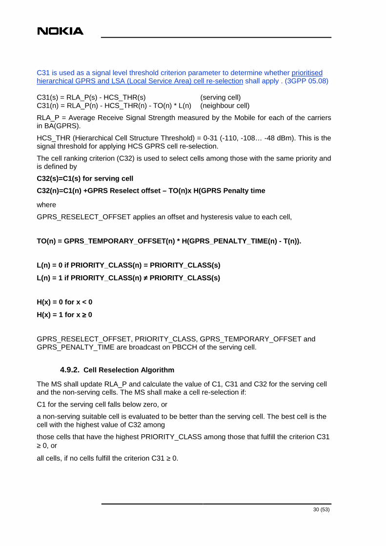
C31 is used as a signal level threshold criterion parameter to determine whether prioritised hierarchical GPRS and LSA (Local Service Area) cell re-selection shall apply . (3GPP 05.08) C31(s) = RLA_P(s) - HCS_THR(s) (serving cell) C31(n) = RLA_P(n) - HCS_THR(n) - TO(n) * L(n) (neighbour cell)
RLA_P = Average Receive Signal Strength measured by the Mobile for each of the carriers in BA(GPRS).
HCS_THR (Hierarchical Cell Structure Threshold) = 0-31 (-110, -108… -48 dBm). This is the signal threshold for applying HCS GPRS cell re-selection.
The cell ranking criterion (C32) is used to select cells among those with the same priority and is defined by
C32(s)=C1(s) for serving cell
C32(n)=C1(n) +GPRS Reselect offset – TO(n)x H(GPRS Penalty time
where
GPRS_RESELECT_OFFSET applies an offset and hysteresis value to each cell,
TO(n) = GPRS_TEMPORARY_OFFSET(n) * H(GPRS_PENALTY_T IME(n) - T(n)).
L(n) = 0 if PRIORITY_CLASS(n) = PRIORITY_CLASS(s)
L(n) = 1 if PRIORITY_CLASS(n) ≠≠≠≠ PRIORITY_CLASS(s)
H(x) = 0 for x < 0
H(x) = 1 for x ≥≥≥≥ 0
GPRS_RESELECT_OFFSET, PRIORITY_CLASS, GPRS_TEMPORARY_OFFSET and GPRS_PENALTY_TIME are broadcast on PBCCH of the serving cell.
4.9.2. Cell Reselection Algorithm
The MS shall update RLA_P and calculate the value of C1, C31 and C32 for the serving cell and the non-serving cells. The MS shall make a cell re-selection if:
C1 for the serving cell falls below zero, or
a non-serving suitable cell is evaluated to be better than the serving cell. The best cell is the cell with the highest value of C32 among
those cells that have the highest PRIORITY_CLASS among those that fulfill the criterion C31 ≥ 0, or
all cells, if no cells fulfill the criterion C31 ≥ 0.

31 (53)
If the parameter C32_QUAL is set, positive GPRS_RESELECT_OFFSET values shall only be applied to the neighbor cell with the highest RLA_P value of those cells for which C32 is compared above.
PRIORITY_CLASS and C32_QUAL are broadcast on PBCCH of the serving cell.
When evaluating the best cell, the following hysteresis values shall be subtracted from the C32 value for the neighbor cells:
in MM standby state, if the new cell is in the same routing area: 0.
in MM ready state, if the new cell is in the same routing area: GPRS_CELL_RESELECT_HYSTERESIS.
If the parameter C31_HYST is set, GPRS_CELL_RESELECT_HYSTERESIS shall also be subtracted from the C31 value for the neighbor cells.
in MM standby or ready state, if the new cell is in a different routing area: RA_RESELECT_HYSTERESIS .
in case of a cell re-selection occurred within the previous 15 seconds: 5 dB.
GPRS_CELL_RESELECT_HYSTERESIS, C31_HYST and RA_RESELECT_HYSTERESIS are broadcast on PBCCH of the serving cell.
4.9.3. Parameters for PBCCH
4.9.3.1. BTS parameters:
GPRS not allowed access classes (GACC)(0 to 9, 11 t o 15)(-)
The status of a cell for cell reselection in combination with cell bar qualify (QUA) parameter is defined with GPRS cell barred (GBAR)(0,1)(0).
Parameters that are used to calculates C31, C32:
GPRS rxLev access min (GRXP)(-110..-47 dBm)(-105 dB m)
GPRS MS txpwr max CCH (GTXP1)(5….39 dBm with 2 dB s teps)(33)
GPRS MS txpwr max CCH 1x00 (GTXP2)(for GSM1800 0…36 dBm in 2 dB steps, for GSM 1900 0…32 dBm with 2 dB steps and 33 dBm)(30)
C31 hysteresis (CHYS)(Y/N)(N)
C32 qual (QUAL)(Y/N)(N) defines an exception of the rule for GPRS cell reselect offset.
Offset values that are applied for cell reselection:
GPRS cell reselect hysteresis (GHYS)(0,2,4,6,8,10,1 2,14 dB)(4dB) applied in READY state for selecting a cell in the same routing area
RA reselect hysteresis (RRH)(0,2,4,6,8,10,12,14 dB) (4dB) applied in STANDBY and READY state for selecting a cell of another routing area
32 (53)
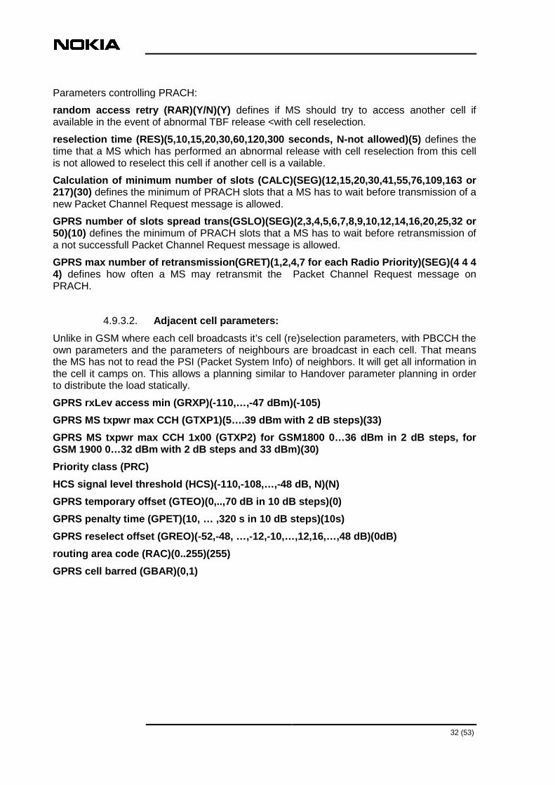
Parameters controlling PRACH:
random access retry (RAR)(Y/N)(Y) defines if MS should try to access another cell if available in the event of abnormal TBF release <with cell reselection.
reselection time (RES)(5,10,15,20,30,60,120,300 sec onds, N-not allowed)(5) defines the time that a MS which has performed an abnormal release with cell reselection from this cell is not allowed to reselect this cell if another cell is a vailable.
Calculation of minimum number of slots (CALC)(SEG)( 12,15,20,30,41,55,76,109,163 or 217)(30) defines the minimum of PRACH slots that a MS has to wait before transmission of a new Packet Channel Request message is allowed.
GPRS number of slots spread trans(GSLO)(SEG)(2,3,4, 5,6,7,8,9,10,12,14,16,20,25,32 or 50)(10) defines the minimum of PRACH slots that a MS has to wait before retransmission of a not successfull Packet Channel Request message is allowed.
GPRS max number of retransmission(GRET)(1,2,4,7 for each Radio Priority)(SEG)(4 4 4 4) defines how often a MS may retransmit the Packet Channel Request message on PRACH.
4.9.3.2. Adjacent cell parameters:
Unlike in GSM where each cell broadcasts it’s cell (re)selection parameters, with PBCCH the own parameters and the parameters of neighbours are broadcast in each cell. That means the MS has not to read the PSI (Packet System Info) of neighbors. It will get all information in the cell it camps on. This allows a planning similar to Handover parameter planning in order to distribute the load statically.
GPRS rxLev access min (GRXP)(-110,…,-47 dBm)(-105)
GPRS MS txpwr max CCH (GTXP1)(5….39 dBm with 2 dB s teps)(33)
GPRS MS txpwr max CCH 1x00 (GTXP2) for GSM1800 0…36 dBm in 2 dB steps, for GSM 1900 0…32 dBm with 2 dB steps and 33 dBm)(30)
Priority class (PRC)
HCS signal level threshold (HCS)(-110,-108,…,-48 dB , N)(N)
GPRS temporary offset (GTEO)(0,..,70 dB in 10 dB st eps)(0)
GPRS penalty time (GPET)(10, … ,320 s in 10 dB step s)(10s)
GPRS reselect offset (GREO)(-52,-48, …,-12,-10,…,12 ,16,…,48 dB)(0dB)
routing area code (RAC)(0..255)(255)
GPRS cell barred (GBAR)(0,1)

33 (53)
4.10. Operation of an TBF
28 BSS´PAR-GPRS & EGPRS/© NOKIA
Establishing a TBF& Sending Data
Uplink
AGCHAvailability
AvailableCapacity
TBF Session Success
PDTCHAvailability
EitherPCUor
TRX
Data Connection Success
ReadyState
sendRACH
EstablishImmediate
Assignment
GetPDCH
Requested
TSLto
Allocated
TBFSession
Releasephase
GPRS & EGPRS
,
Figure 20. ‘ Phases’ of an TBF
4.10.1. DL TBF establishment
The SGSN has to know the cell of the MS. It will send the LLC PDUs to the correct PCU. The PCU allocates one or more PDTCHs for the TBF and indicates that and the TFI to the MS in an assignment message.
A DL TBF may established:
-on PACCH when a concurrent TBF exists (or timer T 3192 is running in the MS)
The PCU sends a PACKET_DOWNLINK_ASSIGNMENT or PACKET_TIMESLOT_RECONFIGURE message. The TBF mode (GPRS/EGPRS) is always the same as the existing UL TBF
-on PCCCH when it is supported and no DL TBF exists (or timer T3192 is not
running)
The PCU allocates one or more PDTCH for the TBF and send a PACKET_DOWNLINK_ASSIGNMENT message to the MS.
-on CCCH without PCCCH and no DL TBF exists (or timer T3192 is not running)
First the PCU allocates one PDTCH and sends a IMMEDIATE_ASSIGNMENT message. The possible multislot allocation is done later with a reallocation message.

34 (53)
29 BSS´PAR-GPRS & EGPRS/© NOKIA
DL TBF ASSIGNMENT (GPRS,EGPRS), MS on CCCH
MS BTS BSC SGSN
P-Immediate Assignment
Immediate Assignment (CCCH)P-Immediate Assignment Ack
Packet Polling Request
Packet Polling Request (PACCH)
Packet Control Ack Packet Control Ack (PACCH)
MS on ready state
Sent on the PDTCH to find out the MS Timing Advance. In Nokia implementation, always sent when DL TBF Assignment is from CCCH. Not sent when DL TBF is assigned on PACCH
Packet Power Control/Timing Advance
Alternatively, Packet Downlink Assignmnet may be sent if more timeslots are required
Packet Power Control/Timing Advance
Only 1 TCH is allocated first.
If requested and available
GPRS & EGPRS
,
Figure 21. ‘ establishment of an UL TBF
4.10.2. UL TBF establishment
MS may ask for UL resources
-on PACCH when a DL TBF exists
The MS will include a Channel Request IE in the PACKET_UPLINK_ACK/NACK message. If there is no need to change the DL configuration, a PACKET_DOWNLINK_ASSIGNMENT is sent by the PCU. IF it fails the DL TBF is released.
If the DL configuration is changed because of for instance due to multislot constraints an PACKET_TIMESLOT_RECONFIGURE message is sent, where MS is informed about UL and DL configuration. –if it fails, both DL and UL TBF are released.
-on PCCCH following establishment causes are supported:
one phase access, GPRS or EGPRS
short access, GPRS or EGPRS
two phase access, GPRS or EGPRS
Signalling access, GPRS or EGPRS
-on CCCH

35 (53)
here in principle the same access causes are supported. An exception is for EDGE MSs, here it depends if EPCR (EDGE_PACKET_CHANNEL_REQUEST) is supported or not. If not supported an EDGE MS is forced to two phase access if it requests EDGE resources. The EPCR is supported by Nokia starting with S11.
4.10.3. During an ongoing TBF
The PCU can whenever needed change the PDTCH configuration by sending a PACKET_TIMESLOT_RECONFIGURE on PACCH. Reasons may be GPRS territory downgrades, concurrent TBF establishments,.. .
The MS will recognize its blocks based on the TFI in DL, in UL it knows when to send it’s blocks according to the USF. Periodically it will be polled for a DL TBF to send PACKET_DOWNLINK_ACK/NACK messages, for a UL TBF it will get PACKET_UPLINK_ACK/NACK messages. These messages control the operation of a TBF. If the messages are not received within some time (ruled by counters like Radio Link Timeout) the TBF will be released.
4.11. Priority Class based QoS
4.11.1. The Concept
30 BSS´PAR-GPRS & EGPRS/© NOKIA
Example of Transmission TurnsGPRS & EGPRS
,
Figure 22. Idea of QoS

36 (53)
At a system level, the concept of ‘Priority Class’ is introduced. This is based on combinations of GPRS Delay class and GPRS Precedence class values (QoS parameters related with one PDP).
The needs from different applications differ and mechanisms to have separate service levels are required. GSM specifications define QoS parameters, which gives a possibility to differentiate TBFs by delay, throughput and priority. Priority Based Scheduling is introduced as the first step towards QoS. With Priority Based Scheduling operator can give users different priorities. Higher priority users will get better service than lower priority users. There will be no extra blocking to any user, only the experienced service quality changes (basically the throughput).
The scheduling algorithm gives each TBF a so-called latest service time before a Radio block is sent. When a block for one TBF has been sent it is given a new latest service time, which is the current time plus a predefined step. With every sent block the service time for all TBFs on that TS is reduced by one. The TBF with the lowest value is seved first. Periodically the scheduling algorithm checks the queue. In Nokia GRPS Release 1 (BSS9), the same stepsize is used for all TBFs.
With the new algorithm no extra blocking is introduced.
There are 4 QoS classes for uplink (based on Radio Priority), and 3 QoS classes for downlink (based on Precedence Class). The Radio Priority related to a certain PDP is told to MS in the PDP context activation.
This algorithm provides priorities between TBFs sharing one timeslot. It guarantees that inside a QoS group the air time is divided equally and that a higher QoS class gets more air time.
Mobile specific flow control is part of the QoS solution in the PCU. This feature works together with the SGSN to provide a steady data flow to the mobile from the network. It also is an effective countermeasure against buffer overflows in the PCU.
Priority Based Scheduling in BSC is standard feature and subscriber priority has to be defined in HLR.
Parameters
DL HIGH PRIORITY SSS (BSC)(1 ... 12)(3)
DL NORMAL PRIORITY SSS(BSC)(1 ... 12)(6)
DL LOW PRIORITY SSS (BSC)(1 ... 12)(12)
UL PRIORITY 1 SSS(BSC)(1 ... 12)(3)
UL PRIORITY 2 SSS(BSC)(1 ... 12)(6)
UL PRIORITY 3 SSS(BSC)(1 ... 12)(9)
UL PRIORITY 4 SSS(BSC)(1 … 12)(12)

37 (53)
31 BSS´PAR-GPRS & EGPRS/© NOKIA
FTP Download with Different QoS FT P download, MCS9
0
20
40
60
80
100
120
kbit
/s Silver
Gold
FTP Download, M CS4
0
5
10
15
20
25
30
35
40
kbit
/s Silver
Gold
FT P Download, CS2
0
5
10
15
20
25
30
kbit/
s Silver
Gold
FTP Download, CS2 & M CS7
0
10
20
30
40
50
kbit/
s CS2, Silver
MCS7, Gold
• 2 timeslots available
• QoS priorities: 3, 6 & 12
GPRS & EGPRS
,
Figure 23. Result of supporting QoS

38 (53)
4.12. GPRS Link Adaptation parameters
32 BSS´PAR-GPRS & EGPRS/© NOKIA
Link Adaptation Algorithm
• The coding scheme will change based on set BLER Thresholds.
• The BLER thresholds are defined by simulations and change from hopping to non hopping networks
From CS1 to CS2= 1- (X kbps/8 kbps)CS1 FH 14%CS1 NFH 69%
From CS2 to CS1= 1 - (X kbps/12kbps)CS2 FH 43%CS2 NFH 79%
X
CS1 & CS2Crosspoint
Frequency Hopping
Throughput
C/I
GPRS & EGPRS
,
Figure 24. LA for GPRS
When the RLC layer is unacknowledged mode Link Adaptation (LA) is not performed and the RLC blocks are encoded in CS-1. For acknowledged Mode LA is switched on by using the parameter
Coding scheme hop(CODH)(BSC)(0,1,2)(0)
Coding scheme no hop(COD)(BSC)(0,1,2)(2)
Range: 0: Link adaptation used.
1: CS 1 used
2: CS 2 used
The LA algorithm supervises the radio conditions by monitoring the RLC block error rate (BLER) for the given coding scheme. The values of BLER to make the transition from one coding scheme to the other can be set in the database.
For LA enabled and non hopping systems:
DL BLER crosspoint for CS selection no hop(SEG)(DLB )(0-100%)(90%)
UL BLER crosspoint for CS selection no hop(SEG)(ULB )(0-100%)(90%)
For LA enabled and hopping systems:
DL BLER crosspoint for CS selection hop(SEG)(DLBH)( 0-100%)(20%)
UL BLER crosspoint for CS selection hop(SEG)(ULBH)( 0-100%)(24%)

39 (53)
The data transfer session will always begin with CS-2 and only change when the BLER is above respectively below the indicated percentages. CS 1 or 2 would give at the indicated points the same effective bit rate.
In acknowledged mode the BLER is calculated from the packet ACK/NACK scheme operated at the RLC layer. In DL the PCU selects the CS. The PCU uses the information received in the Packet Downlink Ack/-nack message to calculate the BLER. To define which CS to use
In UL the MS is informed by the IMMEDIATE ASSIGNMENT or PACKET_UPLINK_ASSIGNMENT message about the initial CS. During the running TBF the channel coding command field in the Packet Uplink ACK/NACK message may be used to inform the MS to use another CS.
There is still another parameter related with LA. The risk level parameters
UL adaptation probability threshold(ULA)(SEG)(0-50% )(10%) and
DL adaptation probability threshold(DLA)(SEG)(0-50% )(20%)
define an allowed probability to make a wrong decision. The larger the risk level, the indicated percentage, the faster LA will react to change to a new CS, but the decision is less reliable.
Note: if there are no resources on the dynamic abis left the system is forced to use CS1!
4.13. EGPRS Link Adaptation parameters
Link adaptation for EDGE is based on Parameters defining the initial MCS (Modulation and Coding scheme) and during an ongoing TBF on the EGPRS Channel Quality Report IE in the EDGPRS PACKET DOWNLINK ACK/NACK message sent by MS for an DL TBF and in UL on measurements done by the BTS. The algorithm is based on BEP (Bit Error Probability) values measured by MS or BTS. These measurements consist of mean (range 0-31) and and cv (coefficient of variation=standard deviation / mean value, range 0-7). The values for choosing Modulation selection and Coding scheme selection are hardcoded. An offset may be defined to push the system to more or less riskier MCSs.

40 (53)
33 BSS´PAR-GPRS & EGPRS/© NOKIA
EGPRS Modulation and Coding Schemes
• EGPRS has nine basic coding schemes, MCS-1...9.
• In general, a higher coding scheme has higher coding rate, and consequently higher peak throughput, but it also tolerates less noise or interference.
• The figure shows throughput vs. C/I of EGPRS coding schemes in TU50iFH.
• The basic unit of transmission is radio block (= 4 bursts = 20 ms on average), which contains one or two RLC blocks.
0
10
20
30
40
50
60
0 5 10 15 20 25 30
MCS-1MCS-2MCS-3MCS-4MCS-5MCS-6MCS-7MCS-8MCS-9
Frequency Hopping Network
Frequency Hopping Network
GPRS & EGPRS
,
Figure 25. LA for EDGE
The following parameters are used in EGPRS link adaptation.
EGPRS Link Adaptation Enabled(ELA)(0,1,2)(2) where
0- means EGPRS LA disabled
1- means EGPRS LA enabled for RLC ACK mode
2- means EGPRS LA enabled for RLC ACK and NACK mode
initMcsAckMode(MCA)(SEG)(1..9)(9) parameter indicates the Modulation and Coding Scheme (MCS) used in the beginning of a TBF for acknowledged mode
initMcsUnackMode(MCU)(SEG)(1..9)(6) parameter indicates the Modulation and Coding Scheme used in the beginning of a TBF for unacknowledged mode
maxBlerAckMode (BLA)(SEG)(10..100%)(90%) parameter is used to indicate maximum block error rate(BLER) of first transmission in acknowledged mode
maxBlerUnackMode (BLU)(SEG)(1..100%)(10%) parameter sets the maximum BLER in unacknowledged mode
meanBepOffsetGMSK (MBG)(SEG)(-31 ..31)(0) parameter is used to adjust the MCS and modulation preferences. This is the offset added to reported GMSK mean BEP values before BEP table lookups. The value applies to both uplink and downlink directions.
meanBepOffset8PSK (MBP)(SEG)(-31 ..31)(0): With this parameter you can adjust the MCS and modulation preferences. This is the offset added to reported 8PSK mean BEP values before BEP table lookups. The value applies to both uplink and downlink directions.

41 (53)
BepPeriod (BEP)(POC)(1,2,3,4,5,7,10,12,15,20,25)(10 ) parameter defines the bit error probability filter averaging period for EGPRS channel quality measurements.
Note: The dynamic Abis may limit the used MCS and so the potential throughput
© NOKIA BSSPAR .2004
GPRS & EGPRS
MCS vs. CI in Time (measurement route)
Worst quality environment
0
1
2
3
4
5
6
7
8
9
0 50 100 150
Time (s)
Cod
ing
Sch
eme
(MC
S)
0
2
4
6
8
10
12
14
16
18
20
CI(
dB)
MCSMeasured C/I
Averaged C/I
Figure 26. Measured C/I versus used MCS in a very bad environment
4.14. GPRS Power control
4.14.1. Uplink power control
Power control in the uplink is supported in order to improve the spectrum efficiency and to reduce the power consumption in the mobile. DL power control is not supported.The MS follows a flexible power control algorithm, which the operator can optimise through a set of parameters. In the current implementation it is an open loop mechanism. The MS measures the received level and calculates it’s out-put-power with the help of parameters set in the system. GPRS Uplink power control is managed with the formula
PCH = min( ΓΓΓΓ0 - ΓΓΓΓCH - α α α α x C + 48),PMAX) (1)
Where ΓΓΓΓCH determines the minimum MS output power. It is sent to the MS in any resource assignment message
ΓΓΓΓ0 = 39 dBm for GSM900

42 (53)
ΓΓΓΓ0 = 36 dBm for GSM1800
C is based on the received signal level measured at the MS.
αααα determines the slope by which the downlink RX_LEVEL effects the power
Pmax is the maximum allowed output power in the cell (broadcast parameter) or the MS power class, whatever is the lowest value.
Both α α α α and ΓΓΓΓCH are cell-specific parameters to be defined by the Network Operator, ΓΓΓΓCH
determines the minimum MS output power and alpha determines the slope by which the downlink RX_Level affects the MS power
Binary representation ALPHA (ALPHA)(POC)(0,1,…,10)( 7 for GSM 800 and 900, 8 for GSM 1800 and 1900) Principle: 0: α=0.0, 1: α=0.1, …, 1: α=1
Binary representation TAU (GAMMA)(POC)(0,1,…,62 dB) (34 for GSM 800 and 900, 36 for GSM 1800 and 1900) defines ΓCH.
36 BSS´PAR-GPRS & EGPRS/© NOKIA
Uplink Power Control
0
20
25
30
35
-48 -50 -52 -54 -56 -58 -60 -62 -64 -66 -68 -70 -72 -74 -76 -78 -80 -82 -84 -86 -88 -90 -92 -94 -96 -98-100-102-104-106-108-110
Signal Strength (dBm)
αααα =0.3
αααα =0.1
MSoutput power
GPRS & EGPRS
,
Figure 27. PC for different values for α
4.14.2. Deriving the C-value
4.14.2.1. in Packet idle mode
In packet idle mode will calculate the C value with the Idle Mode Signal Strength Filter Period. The MS calculates which output power to use on CCCH or PCCCH. The MS

43 (53)
measures the received signal level of each paging block monitored by the MS according to its current DRX mode and its paging group using the algorithm:
Cblock n = SSblock n + Pb
Where:
SSblock n is the mean of the received signal level of the four normal bursts that compose the RLC block.
Pb is the BTS output power reduction relative to the output power used on the BCCH. The Pb value is 0 in the first release.
n is the iteration index, incremented for each RLC block.
Finally, the Cblock n values are filtered with a running average filter :
Cn = (1-a) *Cn-1 + a * Cblock n , C0=0
where a is the forgetting factor :
a = 1/MIN(n, MAX(5, TAVG_W*TDRX)
TDRX = the average number of monitored blocks per multiframe according to its current DRX mode and its paging group.
TAVG_W = is operator definable and broadcast on the BCCH or PBCCH:
Idle mode signal strength filter period(IFP)(POC)(0 …25)(9)
4.14.2.2. in Packet transfer mode
The MS in packet transfer mode will calculate the C value with the help of the Transfer Mode Signal Strength Filter Period. If measurements are done on the BCCH, values are filtered with a running average filter :
Cn = (1-b) * Cn-1 + b* SS n
Where:
SSn is the received signal level of the measurement samples.
b is the forgetting factor: b = 1/(6*TAVG_T)
n is the iteration index. When entering packet transfer mode, the filter shall continue from the n and Cn values obtained during packet idle mode.
If measuring the PDCH, values are filtered with a running average filter :
Cn = (1-c) * Cn-1 + c *Cblock n
where c is the forgetting factor: c = 1/(12*TAVG_T)
and TAVG_T is an operator definable parameter:
transfer mode signal strength filter period (TFP)(P OC)(0-25)(13)

44 (53)
By changing the TAVG_T & TAVG_W parameters the operator can modify the averaging of the field strength values which are used in the uplink power control algorithm. Changing these values the has an impact on how reactive the mobile changes the uplink power with varying downlink field strength.
The following Figure illustrate the effect of having different averaging parameters. It can be seen that having a large averaging parameter makes the mobile less reactive to changing field strengths.
© NOKIA BSSPAR .2004
Uplink Power ControlAveraging Parameters
Mobile Output Power
-80
-60
-40
-20
0
20
40
1 16 31 46 61 76 91 106
121
136
151
166
181
196
211
226
241
256
271
286
301
316
331
346
361
376
391
406
421
436
451
Pow
er
SS
P_IDLE
P_TRANSFER
Mobile Output Power
-80
-60
-40
-20
0
20
40
1 14 27 40 53 66 79 92 105
118
131
144
157
170
183
196
209
222
235
248
261
274
287
300
313
326
339
352
365
378
391
404
417
430
443
Pow
er
Packet Transfer / Idle Mode Signal Strength Filter Period = 25
Packet Transfer / Idle Mode Signal Strength Filter Period = 1
GPRS & EGPRS
,
Figure 28. Calculation of the output power

45 (53)
5. EDGE Dynamic A-bis Pool (EDAP)Creation Parameters
5.1. The concept
Dynamic A-bis allocation in BSS10.5 is a solution for higher data rates of EGPRS to ensure cost efficiency and flexible A-bis transmission capacity addition. The Dynamic A-bis functionality allocates A-bis transmission capacity to cells when needed instead of reserving full fixed transmission link per TRX.
As data rates per radio timeslot can vary between 8.8 and 59.2 kbps, traditional static A-bis allocation does not use transmission resources efficiently. The Dynamic A-bis feature uses existing A-bis more efficiently by splitting PCMs into permanent timeslots for signalling and voice or data and a dynamic pool for data. The pool can be shared by a number of transceivers. The Dynamic A-bis transmission solution saves up to 70% in the A-bis transmission expansion cost as it allows A-bis dimensioning to be performed near to the average data rates instead of peak rates. This also applies to the number of 2M BSC interfaces needed.
Dynamic A-bis is implemented as a software feature. Quality of service is improved by the Dynamic A-bis method, which uses allocation of circuit switched connections under real time centralised control. The implementation of shared transmission channel connection pools is supported by Nokia cellular transmission cross connection products and made easy with the Nokia NetAct transmission network planning tool.

46 (53)
© NOKIA BSSPAR .2004
Dynamic A-bisGPRS & EGPRS
Figure 29. Dynamic A-bis
Traditional (not EDGE) TRXs are connected to BSC with a 16 kbps point-to-point link from the RTSL to the BSC (nothing new).
For EDGE TRXs each RTSL again is linked to one 16 kbit/s subslot on one PCM. Signalling (TRXSIG, BCFSIG) is configured as before. But still remaining consecutive subslots on that PCM can be allocated to the EDAP. EDAP has to be on the same PCM as TRXSIG. The BSC allocates A-bis capacity for calls as before. For EDGE or GPRS resources more capacity may be required depending on the used MCS, CS. Additional capacity is taken from EDAP. There are master and slave Abis subslots. The master can be found on the fixed allocated Abis resources the slave(s) is/are taken from the pool. One Pool may serve several EDGE TRXs.
5.2. Parameters

47 (53)
37 BSS´PAR-GPRS & EGPRS/© NOKIA
EGPRS Dynamic Abis Requirement for CS and MCS
Coding scheme Data rate
MCS-1 8.8 kbit/s
MCS-2 11.2 kbit/s
MCS-3 14.8 kbit/s
MCS-4 17.6 kbit/s
MCS-5 22.4 kbit/s
MCS-6 29.6 kbit/s
MCS-7 44.8 kbit/s
MCS-8 54.4 kbit/s
MCS-9 59.2 kbit/s
Abis PCM allocation
(fixed + pool)
GPRS & EGPRS
Coding scheme Data rate
CS-1 8.8 kbit/s
CS-2 11.2 kbit/s
CS-3 14.8 kbit/s
CS-4 17.6 kbit/sNot supported
,
Figure 30. number of sub slots used Features DYN_ABIS_IN_USE and EGPRS_USAGE have to be enabled.
Identification(ID)(DAP)(1…470)(-) identifies unique the DAP in the BSC, it is allocated by creating of a DAP.
Abis interface ET-PCM number and first TSL of the p ool; Circuit(DAP)(CRCT PCM:1 …255, CRT TSLs: 1…30 for ETSI, 1…23 in ANSI)(-) defines on which PCM and the first TSL on that PCM used for a certain pool. The last TSL may be given as well. The maximum size for one POOL is 24 TSL
One pool is controlled by one PCU. The PCU is identified by the PCU index(PCU)(DAP)(0,..,254)(-) . That means as well, that with the Dynamic Abis Feature one PCU serves a certain number of cells. The dynamic mechanism where the system allocates during power on cells to a certain PCU is disabled. The BCSU which controls one DAP is identified with the BCSU number (BCSU)(DAP)(0,…,8)(-)
5.3. Limitations of the Dynamic Abis:
Only EDGE capable TRXs are enabled to be connected to EDAP
1 EDAP has to be served by one PCU and configured to one PCM, it can not be shared between different PCUPCMs
One pool should be reserved for one BCF cabinet.
5.4. Capacity of one PCU
One PCU has got 16 DSP (Digital Signalling Processors) cores. Each DSP can handle up to 20 x 16 kbit/s Abis channels (EGPRS, GPRS, PBCCH channels). One EDAP may be served

48 (53)
by several DSPs but one DSP can only serve one EDAP. The allocation about which DAP handles which EDAP is done during creation of EDAPs.
5.5. Capacity of Dynamic Abis
If not enough 16 kbit/s subslots can be found, UL TBFs may have to be rejected, lower MCSs may be used as it could be possible. For UL the system will allocate EDAP resources for the lifetime of a TBF according to the highest MCS allowed, a MS may use a lower MCS/CS as EDAP resources are allocated.
Counters indicate problems with EDAP resources. The operator may then
-increase the EDAP size
-Decrease the number of EDGE TRXs or EDGE channels
-sharing the load between the PCUs
-decrease the initial MCS for TBFs

49 (53)
6. Interworking with other features
6.1. Allocation of speech calls and GPRS
The parameter CS TCH allocate RTSL 0 (CTR)(BSC)(Y/N)(N) defines if RTSL 0 is preferred to be allocated before GPRS territory RTSL (setting it to Y) or first the GPRS territory(setting it to N). the parameter is only relevant for BB hopping systems.
For load dependant activation of HR it is possible to define if RTSLs in the current PS territory (excluding reserved RTSLs for GPRS) are seen as idle or busy. This is done by setting the parameter CS TCH allocation calculation to(CTC)(BSC)((0,1,2)( 0)
0 means only CS RTSL are used for calculation
1 means CS and PS used. But for PS resources only currently not used RTSL are seen as idle, available
2 means all RTSLs in the PS territory (apart from reserved ones, if used or not) are seen as available.
6.2. MultiBCF/BCCH features
The multi BCF/BCCH feature allows the configuration of several GPRS/EGPRS territories on different BTSs in one cell (Segment). The system requires mechanisms to distribute the load, TBFs. If there is a EGPRS and GPRS territory the system tries to separate EDGE and non EDGE MSs. For the multi BCCH feature there may be GPRS territories on different bands. The system evaluates the capabilities of MSs and the level to distribute the load.

50 (53)
© NOKIA BSSPAR .2004
EGPRS TBF (re)allocation Based on RX_LEV Measurement (concept)
RxLev
BTS 1
BTS 2
-48
Time
Segment 1
NBL (Offset) is used to esimate the level difference between BandsGRPSNonBCCHlayerRxlevUpperLimit = -48
GRPSNonBCCHlayerRxlevLowerLimit = -70
GRPSNonBCCHlayerRxlevLowerLimit = -110
GRPSNonBCCHlayerRxlevUpperLimit = -60
GPRS & EGPRS
,
Figure 31. Multi BCCH and GPRS
gprsNonBCCHRxlevUpper (GPU)(BTS)(-110 .. -47 dBm)(- 95 dBm) sets the minimum power level the MS has to receive to allocate resources from the BTS.
gprsNonBCCHRxlevLower (GPL)(BTS)(-110..-47 dBm)(-10 0 dBm): With this parameter, you define the threshold when reallocation to better BTS in SEG must be done. BTSs preferred with direct GPRS access threshold are selected.
directGPRSaccessBts (DIRE)(BTS)(-10 .. 10 dBm)(0 dB m): With this parameter you define which BTSs may be used for GPRS or EGPRS without signal level measurements. This parameter defines the signal level compared to non BCCH layer offset. When the value of this parameter is higher than the value of the parameter non BCCH layer offset the direct GPRS access to non BCCH layer BTS is applied. This is used in initial channel allocation and reallocation.
The GSM parameter BTS load in SEG(LSEG)(BTS)(0-100%)(70) is used to distribute the traffic between the BTSs. Here RTSLs in the GPRS territory are seen as occupied resources.
6.3. General notes
-Satellite Abis is not supported
-GPRS Territory can not be configured to the extended cell range

51 (53)
-in IUO super reuse frequencies cannot carry GPRS traffic
-with Baseband hopping GPRS territory won’t be allocated to any RTSL 0
-PBCCH has to be configured on the BCCH carrier
-Network mode of operation III is not supported (with PBCCH Gs interface has to be supported)
38 BSS´PAR-GPRS & EGPRS/© NOKIA
Extended Cell
• GPRS is NOT supported in the extended cell range (i.e. E-TRX cannot carry GPRS traffic channels)
• If the MS moves out of normal cell area to the area of an extendedcell area, the TBF is released
BTS
Extended cell coverage
GPRS & EGPRS
,
Figure 32. Extended cell and GPRS

52 (53)
7. Appendix
How many Timeslots? The multislot classes of MSs (according to 3GPP TS 05.02)
Multislot class
Maximum number of slots Minimum number of slots Type
Rx Tx Sum Tta Ttb Tra Trb 1 1 1 2 3 2 4 2 1 2 2 1 3 3 2 3 1 1 3 2 2 3 3 2 3 1 1 4 3 1 4 3 1 3 1 1 5 2 2 4 3 1 3 1 1 6 3 2 4 3 1 3 1 1 7 3 3 4 3 1 3 1 1 8 4 1 5 3 1 2 1 1 9 3 2 5 3 1 2 1 1
10 4 2 5 3 1 2 1 1 11 4 3 5 3 1 2 1 1 12 4 4 5 2 1 2 1 1 13 3 3 NA NA a) 3 a) 2 14 4 4 NA NA a) 3 a) 2 15 5 5 NA NA a) 3 a) 2 16 6 6 NA NA a) 2 a) 2 17 7 7 NA NA a) 1 0 2 18 8 8 NA NA 0 0 0 2 19 6 2 NA 3 b) 2 c) 1 20 6 3 NA 3 b) 2 c) 1 21 6 4 NA 3 b) 2 c) 1 22 6 4 NA 2 b) 2 c) 1 23 6 6 NA 2 b) 2 c) 1 24 8 2 NA 3 b) 2 c) 1 25 8 3 NA 3 b) 2 c) 1 26 8 4 NA 3 b) 2 c) 1 27 8 4 NA 2 b) 2 c) 1 28 8 6 NA 2 b) 2 c) 1 29 8 8 NA 2 b) 2 c) 1
a) = 1 with frequency hopping. = 0 without frequency hopping. b) = 1 with frequency hopping or change from Rx to Tx. = 0 without frequency hopping and no change from Rx to Tx. c) = 1 with frequency hopping or change from Tx to Rx.
= 0 without frequency hopping and no change from Tx to Rx.
Type 1 MS are not required to transmit and receive at the same time.
Type 2 MS are required to be able to transmit and receive at the same time.
For HSCSD, only multislot classes 1 - 18 are recognised. An MS with a higher multislot class number shall indicate a suitable multislot class less than 19 for HSCSD applications (see 3GPP TS 04.08).
53 (53)
Rx:
Rx describes the maximum number of receive timeslots that the MS can use per TDMA frame. The MS must be able to support all integer values of receive TS from 0 to Rx (depending on the services supported by the MS). The receive TS need not be contiguous. For type 1 MS, the receive TS shall be allocated within window of size Rx, and no transmit TS shall occur between receive TS within a TDMA frame.
Tx:
Tx describes the maximum number of transmit timeslots that the MS can use per TDMA frame. The MS must be able to support all integer values of transmit TS from 0 to Tx (depending on the services supported by the MS). The transmit TS need not be contiguous. For type 1 MS, the transmit TS shall be allocated within window of size Tx, and no receive TS shall occur between transmit TS within a TDMA frame.
Sum:
Sum is the total number of uplink and downlink TS that can actually be used by the MS per TDMA frame. The MS must be able to support all combinations of integer values of Rx and Tx TS where 1 <= Rx + Tx <= Sum (depending on the services supported by the MS). Sum is not applicable to all classes.
Tta:
Tta relates to the time needed for the MS to perform adjacent cell signal level measurement and get ready to transmit.
For type 1 MS it is the minimum number of timeslots that will be allowed between the end of the previous transmit or receive TS and the next transmit TS when measurement is to be performed between. It should be noted that, in practice, the minimum time allowed may be reduced by amount of timing advance.
For type 1 MS that supports extended TA, the parameter Tta is increased by 1 if TA > 63 and there is a change from RX to TX.
For type 2 MS it is not applicable.