Embed Size (px)
Citation preview
TEST REPORT
Date: ESPOO 05.06.2006 Page: 1 (27)
Appendices −
Date of handing in: 01.06.2006 Number: 66937R1
Measured by: No. 1 / 1 Timo Hietala, Test Engineer
Reviewed by:
Jyrki Leino, Manager SORT OF EQUIPMENT: WCDMA Base Station RF module
MARKETING NAME: Nokia Flexi BTS RF module 1.7GHz/2.1GHz
TYPE: FRIA
MANUFACTURER: Nokia Corporation
FCC ID: UAFFRIA-01
CLIENT: Nokia Corporation
ADDRESS: P.O.Box 319, FI-90651 OULU, FINLAND
TELEPHONE: +358 7180 08000
TEST LABORATORY: NET/IMN Oulu
FCC REG. NO. 411251 REFERENCE: FCC Part 27, SUBPART L
SUMMARY:
In regard to the performed tests the equipment under test fulfils the requirements defined in the test specifications, see page 4 for details
The test results are valid for the tested unit only. Without a written permission of Nemko Oy it is allowed to copy this report as a whole, but not partially.
Nemko Oy • P.O.Box 19, FI-02601 Espoo, Finland Street address: Perkkaantie 11, FI-02600 Espoo Telephone +358 (0)424 5454 1 • Telefax +358 (0)9 5489 6371 Ve
rsio
n f1
.00
FCC ID: UAFFRIA-01 Type: FRIA
FCC PART 27, SUBPART L Test report No.: 66937R1
Page 2 (27) Date
05.06.2006
Contents
1. EUT and Accessory Information .........................................................................................................3 1.1 EUT description ........................................................................................................................3 1.2 EUT and accessories................................................................................................................3
Summary of Test Data .............................................................................................................................4
2. General Equipment Specification .......................................................................................................5
3. RF Power Output ................................................................................................................................7
4. 99% Occupied Bandwidth...................................................................................................................9
5. Spurious Emissions at Antenna Terminals .......................................................................................11
6. Field Strength of Spurious ................................................................................................................16
7. Frequency stability ............................................................................................................................19
8. List of test equipment........................................................................................................................21
9. Photographs of Test Setup ...............................................................................................................22
10. ANNEX A, TEST DETAILS...............................................................................................................24
11. ANNEX B, TEST DIAGRAMS...........................................................................................................26
FCC ID: UAFFRIA-01 Type: FRIA
FCC PART 27, SUBPART L Test report No.: 66937R1
Page 3 (27) Date
05.06.2006
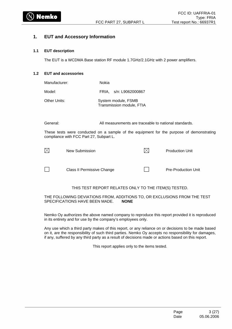
1. EUT and Accessory Information
1.1 EUT description
The EUT is a WCDMA Base station RF module 1.7GHz/2.1GHz with 2 power amplifiers.
1.2 EUT and accessories
Manufacturer: Nokia Model: FRIA, s/n: L9062000867 Other Units: System module, FSMB
Transmission module, FTIA
General: All measurements are traceable to national standards. These tests were conducted on a sample of the equipment for the purpose of demonstrating compliance with FCC Part 27, Subpart L.
New Submission Production Unit
Class II Permissive Change Pre-Production Unit
THIS TEST REPORT RELATES ONLY TO THE ITEM(S) TESTED. THE FOLLOWING DEVIATIONS FROM, ADDITIONS TO, OR EXCLUSIONS FROM THE TEST SPECIFICATIONS HAVE BEEN MADE. NONE Nemko Oy authorizes the above named company to reproduce this report provided it is reproduced in its entirety and for use by the company’s employees only.
Any use which a third party makes of this report, or any reliance on or decisions to be made based on it, are the responsibility of such third parties. Nemko Oy accepts no responsibility for damages, if any, suffered by any third party as a result of decisions made or actions based on this report.
This report applies only to the items tested.
FCC ID: UAFFRIA-01 Type: FRIA
FCC PART 27, SUBPART L Test report No.: 66937R1
Page 4 (27) Date
05.06.2006
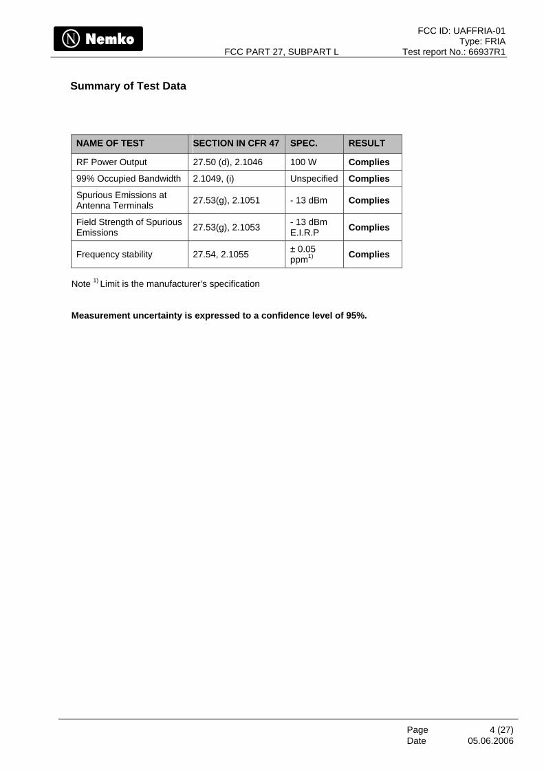
Summary of Test Data
NAME OF TEST SECTION IN CFR 47 SPEC. RESULT
RF Power Output 27.50 (d), 2.1046 100 W Complies
99% Occupied Bandwidth 2.1049, (i) Unspecified Complies
Spurious Emissions at Antenna Terminals 27.53(g), 2.1051 - 13 dBm Complies
Field Strength of Spurious Emissions 27.53(g), 2.1053 - 13 dBm
E.I.R.P Complies
Frequency stability 27.54, 2.1055 ± 0.05 ppm1) Complies
Note 1) Limit is the manufacturer’s specification Measurement uncertainty is expressed to a confidence level of 95%.
FCC ID: UAFFRIA-01 Type: FRIA
FCC PART 27, SUBPART L Test report No.: 66937R1
Page 5 (27) Date
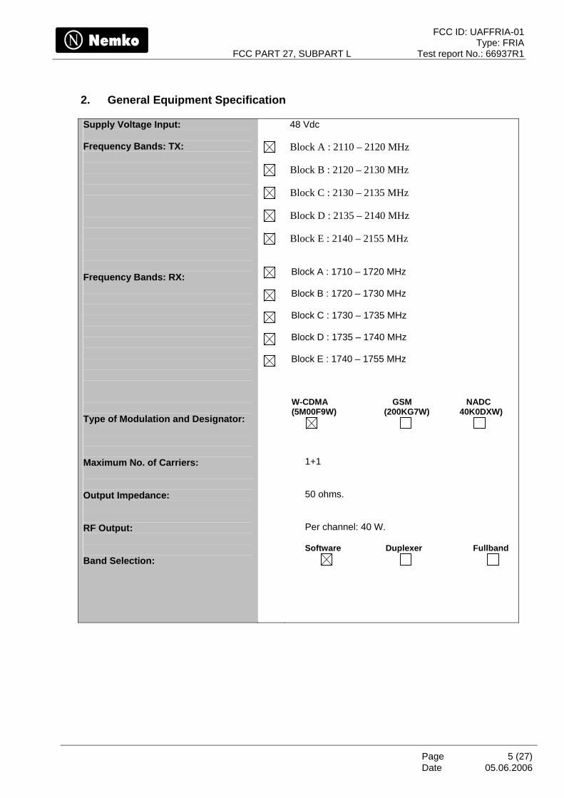
2. General Equipment Specification
05.06.2006
Supply Voltage Input: Frequency Bands: TX:
Frequency Bands: RX: Type of Modulation and Designator: Maximum No. of Carriers: Output Impedance: RF Output: Band Selection:
48 Vdc Block A : 2110 – 2120 MHz
Block B : 2120 – 2130 MHz
Block C : 2130 – 2135 MHz
Block D : 2135 – 2140 MHz
Block E : 2140 – 2155 MHz
Block A : 1710 – 1720 MHz Block B : 1720 – 1730 MHz Block C : 1730 – 1735 MHz Block D : 1735 – 1740 MHz Block E : 1740 – 1755 MHz
W-CDMA GSM NADC (5M00F9W) (200KG7W) 40K0DXW)
1+1 50 ohms. Per channel: 40 W. Software Duplexer Fullband
FCC ID: UAFFRIA-01 Type: FRIA
FCC PART 27, SUBPART L Test report No.: 66937R1
Page 6 (27) Date
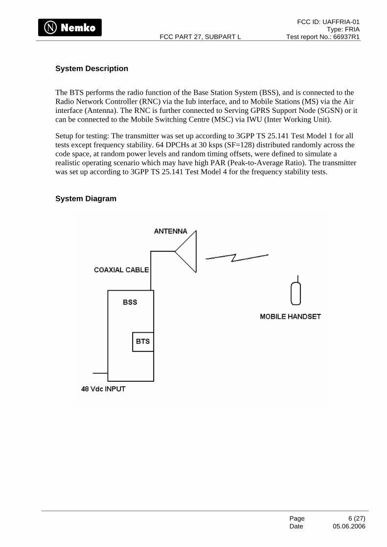
System Description
The BTS performs the radio function of the Base Station System (BSS), and is connected to the Radio Network Controller (RNC) via the Iub interface, and to Mobile Stations (MS) via the Air interface (Antenna). The RNC is further connected to Serving GPRS Support Node (SGSN) or it can be connected to the Mobile Switching Centre (MSC) via IWU (Inter Working Unit).
Setup for testing: The transmitter was set up according to 3GPP TS 25.141 Test Model 1 for all tests except frequency stability. 64 DPCHs at 30 ksps (SF=128) distributed randomly across the code space, at random power levels and random timing offsets, were defined to simulate a realistic operating scenario which may have high PAR (Peak-to-Average Ratio). The transmitter was set up according to 3GPP TS 25.141 Test Model 4 for the frequency stability tests. System Diagram
05.06.2006
FCC ID: UAFFRIA-01 Type: FRIA
FCC PART 27, SUBPART L Test report No.: 66937R1
Page 7 (27) Date
05.06.2006
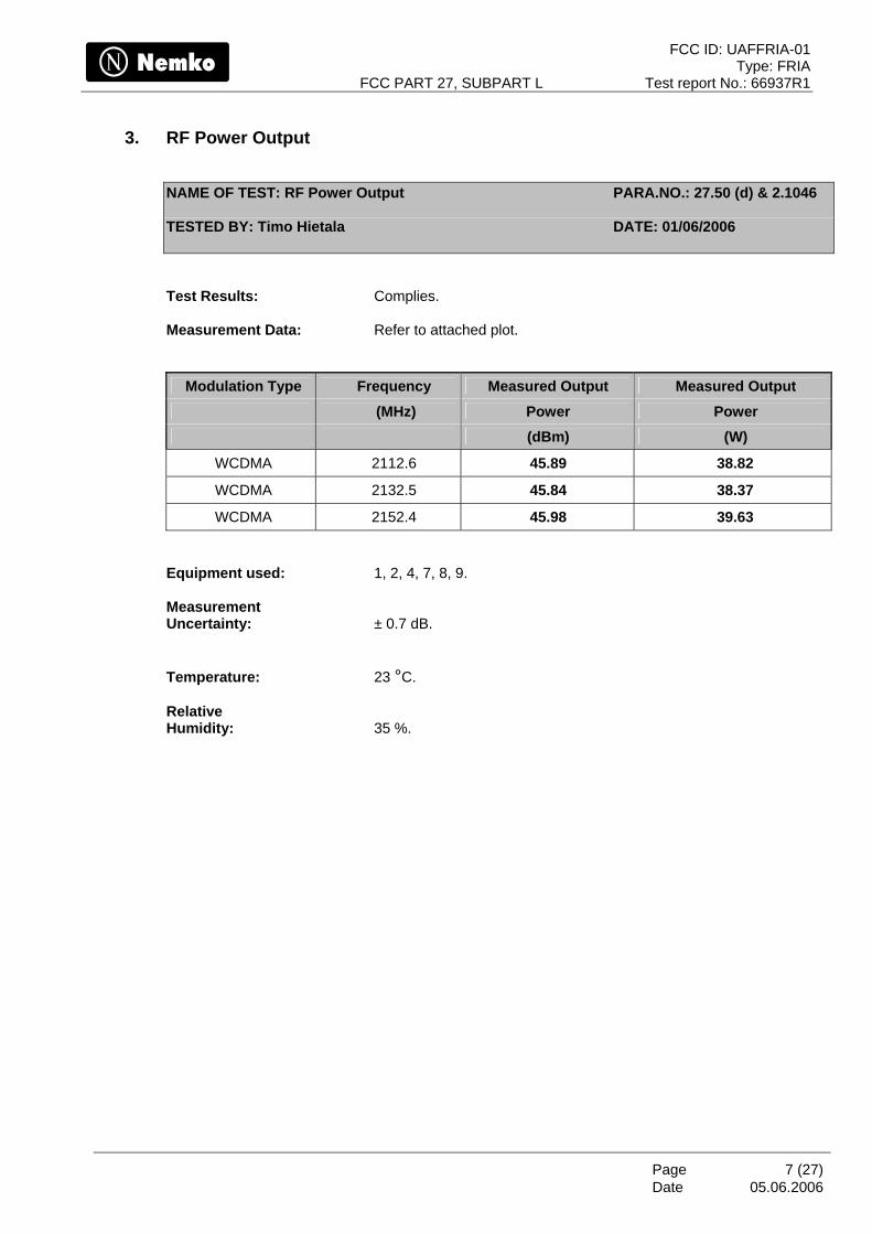
3. RF Power Output
NAME OF TEST: RF Power Output PARA.NO.: 27.50 (d) & 2.1046
TESTED BY: Timo Hietala DATE: 01/06/2006
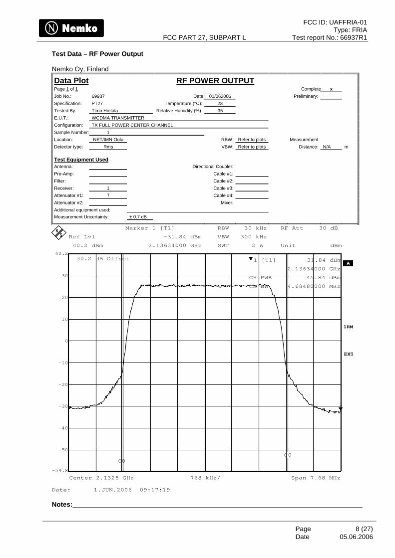
Test Results: Complies. Measurement Data: Refer to attached plot.
Modulation Type Frequency Measured Output Measured Output (MHz) Power Power (dBm) (W)
WCDMA 2112.6 45.89 38.82
WCDMA 2132.5 45.84 38.37
WCDMA 2152.4 45.98 39.63 Equipment used: 1, 2, 4, 7, 8, 9. Measurement Uncertainty: ± 0.7 dB. Temperature: 23 °C. Relative Humidity: 35 %.
FCC ID: UAFFRIA-01 Type: FRIA
FCC PART 27, SUBPART L Test report No.: 66937R1
Page 8 (27) Date
Test Data – RF Power Output Nemko Oy, Finland
Data Plot RF POWER OUTPUT Page 1 of 1 Complete x Job No.: 69937 Date: 01/062006 Preliminary: Specification: PT27 Temperature (°C): 23 Tested By: Timo Hietala Relative Humidity (%): 35 E.U.T.: WCDMA TRANSMITTER Configuration: TX FULL POWER CENTER CHANNEL Sample Number: 1 Location: NET/IMN Oulu RBW: Refer to plots Measurement Detector type: Rms VBW: Refer to plots Distance: N/A m
Test Equipment Used Antenna: Directional Coupler: Pre-Amp: Cable #1: Filter: Cable #2: Receiver: 1 Cable #3: Attenuator #1: 7 Cable #4: Attenuator #2: Mixer: Additional equipment used: Measurement Uncertainty: ± 0.7 dB
RBW 30 kHz
VBW 300 kHz
SWT 2 s
A
1RM
Unit dBm
30.2 dB Offset
768 kHz/Center 2.1325 GHz Span 7.68 MHz
EXT
Ref Lvl
40.2 dBm
Ref Lvl
40.2 dBm
RF Att 30 dB
-50
-40
-30
-20
-10
0
10
20
30
-59.8
40.2
1
Marker 1 [T1]
-31.84 dBm
2.13634000 GHz
1 [T1] -31.84 dBm
2.13634000 GHz
CH PWR 45.84 dBm
CH BW 4.68480000 MHz
C0C0
Date: 1.JUN.2006 09:17:19 Notes:
05.06.2006
FCC ID: UAFFRIA-01 Type: FRIA
FCC PART 27, SUBPART L Test report No.: 66937R1
Page 9 (27) Date
05.06.2006
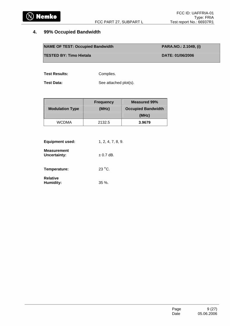
4. 99% Occupied Bandwidth
NAME OF TEST: Occupied Bandwidth PARA.NO.: 2.1049, (i)
TESTED BY: Timo Hietala DATE: 01/06/2006
Test Results: Complies. Test Data: See attached plot(s).
Frequency Measured 99% Modulation Type (MHz) Occupied Bandwidth
(MHz)
WCDMA 2132.5 3.9679 Equipment used: 1, 2, 4, 7, 8, 9. Measurement Uncertainty: ± 0.7 dB. Temperature: 23 °C. Relative Humidity: 35 %.
FCC ID: UAFFRIA-01 Type: FRIA
FCC PART 27, SUBPART L Test report No.: 66937R1
Page 10 (27) Date
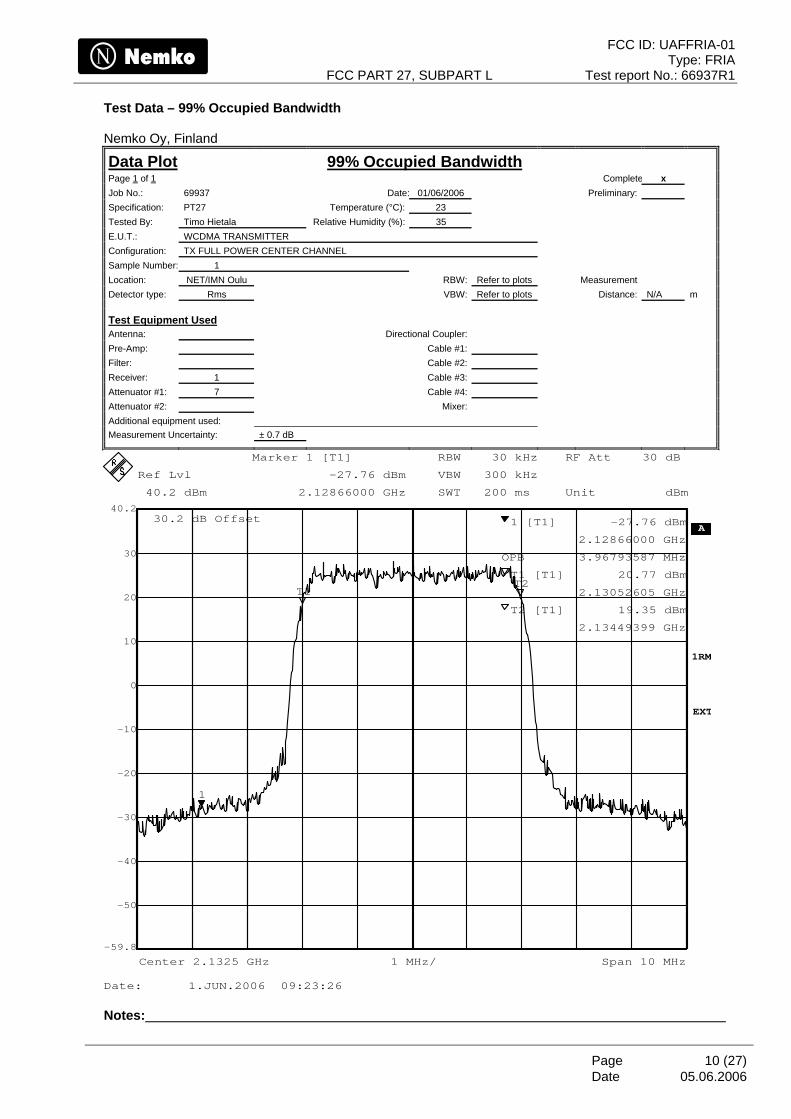
Test Data – 99% Occupied Bandwidth Nemko Oy, Finland
Data Plot 99% Occupied Bandwidth Page 1 of 1 Complete x Job No.: 69937 Date: 01/06/2006 Preliminary: Specification: PT27 Temperature (°C): 23 Tested By: Timo Hietala Relative Humidity (%): 35 E.U.T.: WCDMA TRANSMITTER Configuration: TX FULL POWER CENTER CHANNEL Sample Number: 1 Location: NET/IMN Oulu RBW: Refer to plots Measurement Detector type: Rms VBW: Refer to plots Distance: N/A m
Test Equipment Used Antenna: Directional Coupler: Pre-Amp: Cable #1: Filter: Cable #2: Receiver: 1 Cable #3: Attenuator #1: 7 Cable #4: Attenuator #2: Mixer: Additional equipment used: Measurement Uncertainty: ± 0.7 dB
Ref Lvl
40.2 dBm
Ref Lvl
40.2 dBm
RBW 30 kHz
VBW 300 kHz
SWT 200 ms
RF Att 30 dB
A
1RM
Unit dBm
1 MHz/Center 2.1325 GHz Span 10 MHz
30.2 dB Offset
EXT
-50
-40
-30
-20
-10
0
10
20
30
-59.8
40.2
1
T1T2
Marker 1 [T1]
-27.76 dBm
2.12866000 GHz
1 [T1] -27.76 dBm
2.12866000 GHz
OPB 3.96793587 MHz
T1 [T1] 20.77 dBm
2.13052605 GHz
T2 [T1] 19.35 dBm
2.13449399 GHz
Date: 1.JUN.2006 09:23:26 Notes:
05.06.2006
FCC ID: UAFFRIA-01 Type: FRIA
FCC PART 27, SUBPART L Test report No.: 66937R1
Page 11 (27) Date
05.06.2006
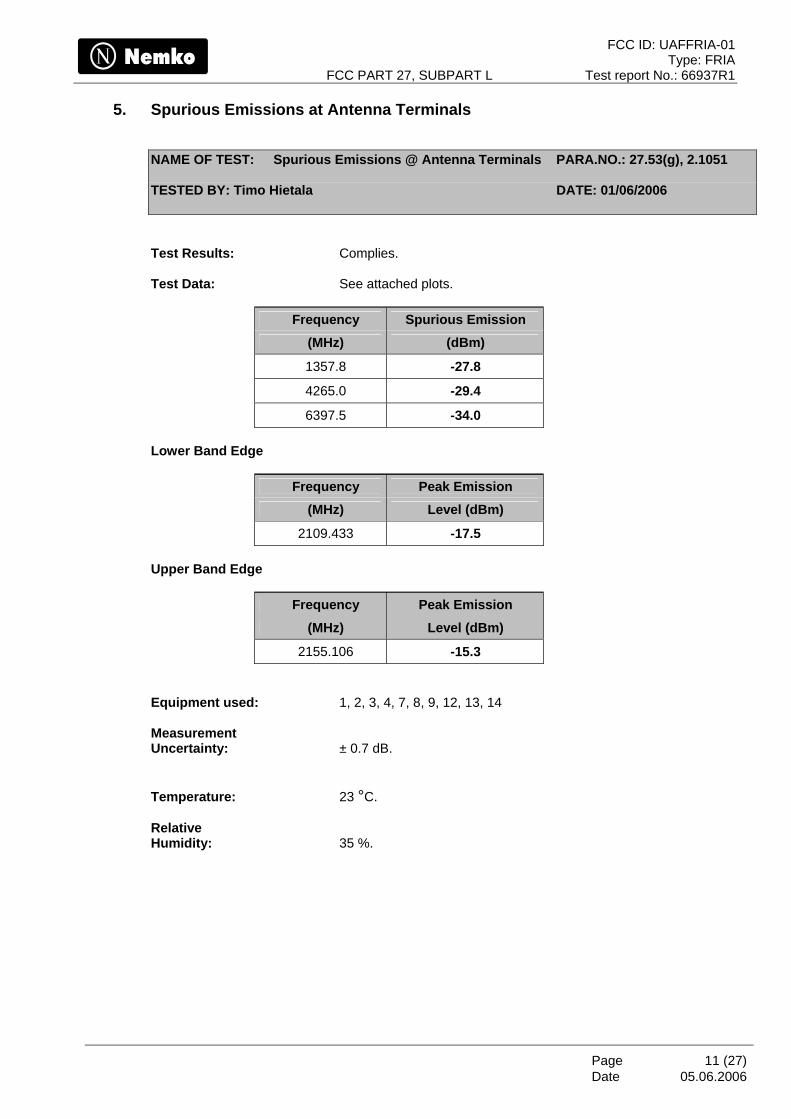
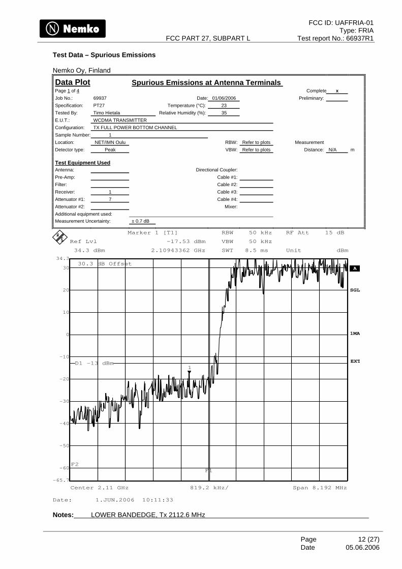
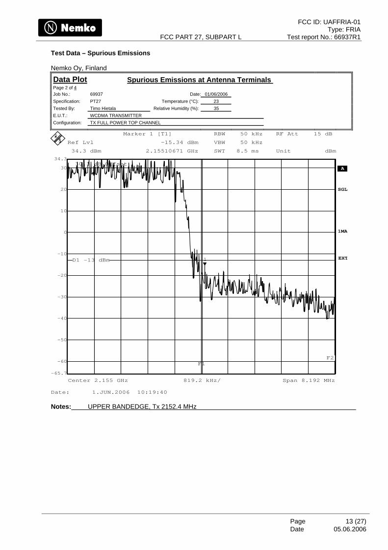
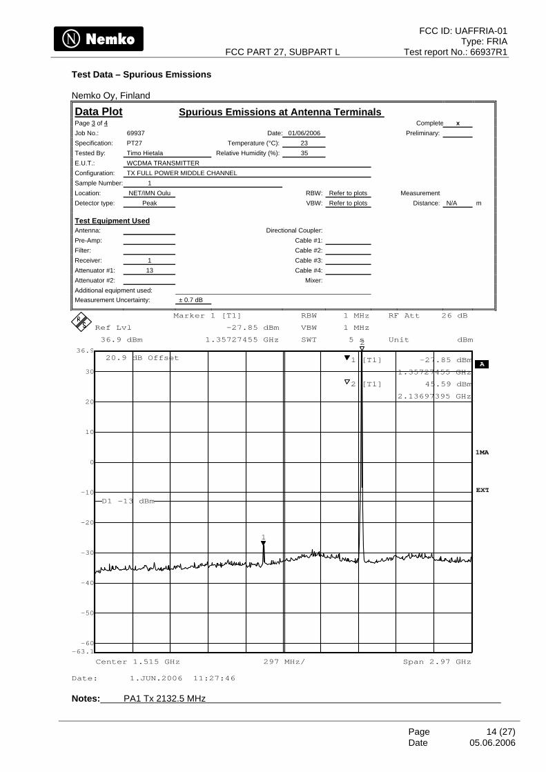
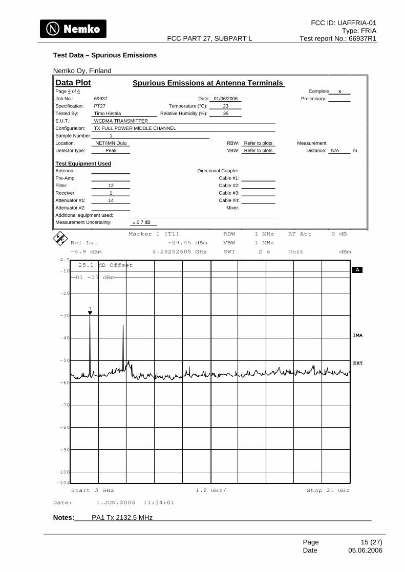
5. Spurious Emissions at Antenna Terminals
NAME OF TEST: Spurious Emissions @ Antenna Terminals PARA.NO.: 27.53(g), 2.1051
TESTED BY: Timo Hietala DATE: 01/06/2006
Test Results: Complies. Test Data: See attached plots.
Frequency Spurious Emission (MHz) (dBm)
1357.8 -27.8
4265.0 -29.4
6397.5 -34.0 Lower Band Edge
Frequency Peak Emission (MHz) Level (dBm)
2109.433 -17.5 Upper Band Edge
Frequency Peak Emission (MHz) Level (dBm)
2155.106 -15.3 Equipment used: 1, 2, 3, 4, 7, 8, 9, 12, 13, 14 Measurement Uncertainty: ± 0.7 dB. Temperature: 23 °C. Relative Humidity: 35 %.
FCC ID: UAFFRIA-01 Type: FRIA
FCC PART 27, SUBPART L Test report No.: 66937R1
Page 12 (27) Date
Test Data – Spurious Emissions Nemko Oy, Finland
Data Plot Spurious Emissions at Antenna Terminals Page 1 of 4 Complete x Job No.: 69937 Date: 01/06/2006 Preliminary: Specification: PT27 Temperature (°C): 23 Tested By: Timo Hietala Relative Humidity (%): 35 E.U.T.: WCDMA TRANSMITTER Configuration: TX FULL POWER BOTTOM CHANNEL Sample Number: 1 Location: NET/IMN Oulu RBW: Refer to plots Measurement Detector type: Peak VBW: Refer to plots Distance: N/A m
Test Equipment Used Antenna: Directional Coupler: Pre-Amp: Cable #1: Filter: Cable #2: Receiver: 1 Cable #3: Attenuator #1: 7 Cable #4: Attenuator #2: Mixer: Additional equipment used: Measurement Uncertainty: ± 0.7 dB
Ref Lvl
34.3 dBm
Ref Lvl
34.3 dBm
RBW 50 kHz
VBW 50 kHz
SWT 8.5 ms
RF Att 15 dB
30.3 dB Offset A
1MA
Unit dBm
819.2 kHz/Center 2.11 GHz Span 8.192 MHz
EXT
SGL
-60
-50
-40
-30
-20
-10
0
10
20
30
-65.7
34.3
1
Marker 1 [T1]
-17.53 dBm
2.10943362 GHz
D1 -13 dBm
F1F2
Date: 1.JUN.2006 10:11:33 Notes: LOWER BANDEDGE, Tx 2112.6 MHz
05.06.2006
FCC ID: UAFFRIA-01 Type: FRIA
FCC PART 27, SUBPART L Test report No.: 66937R1
Page 13 (27) Date
Test Data – Spurious Emissions Nemko Oy, Finland
Data Plot Spurious Emissions at Antenna Terminals Page 2 of 4 Job No.: 69937 Date: 01/06/2006 Specification: PT27 Temperature (°C): 23 Tested By: Timo Hietala Relative Humidity (%): 35 E.U.T.: WCDMA TRANSMITTER Configuration: TX FULL POWER TOP CHANNEL
Ref Lvl
34.3 dBm
Ref Lvl
34.3 dBm
RBW 50 kHz
VBW 50 kHz
SWT 8.5 ms
RF Att 15 dB
30.3 dB Offset A
1MA
Unit dBm
819.2 kHz/Center 2.155 GHz Span 8.192 MHz
EXT
SGL
-60
-50
-40
-30
-20
-10
0
10
20
30
-65.7
34.3
1
Marker 1 [T1]
-15.34 dBm
2.15510671 GHz
D1 -13 dBm
F1F2
Date: 1.JUN.2006 10:19:40 Notes: UPPER BANDEDGE, Tx 2152.4 MHz
05.06.2006
FCC ID: UAFFRIA-01 Type: FRIA
FCC PART 27, SUBPART L Test report No.: 66937R1
Page 14 (27) Date
Test Data – Spurious Emissions Nemko Oy, Finland
Data Plot Spurious Emissions at Antenna Terminals Page 3 of 4 Complete x Job No.: 69937 Date: 01/06/2006 Preliminary: Specification: PT27 Temperature (°C): 23 Tested By: Timo Hietala Relative Humidity (%): 35 E.U.T.: WCDMA TRANSMITTER Configuration: TX FULL POWER MIDDLE CHANNEL Sample Number: 1 Location: NET/IMN Oulu RBW: Refer to plots Measurement Detector type: Peak VBW: Refer to plots Distance: N/A m
Test Equipment Used Antenna: Directional Coupler: Pre-Amp: Cable #1: Filter: Cable #2: Receiver: 1 Cable #3: Attenuator #1: 13 Cable #4: Attenuator #2: Mixer: Additional equipment used: Measurement Uncertainty: ± 0.7 dB
RBW 1 MHz
SWT 5 s
A
Unit dBm
VBW 1 MHz
1MA
RF Att 26 dB
20.9 dB Offset
Ref Lvl
36.9 dBm
Ref Lvl
36.9 dBm
297 MHz/Center 1.515 GHz Span 2.97 GHz
EXT
-60
-50
-40
-30
-20
-10
0
10
20
30
-63.1
36.9
1
2
Marker 1 [T1]
-27.85 dBm
1.35727455 GHz
1 [T1] -27.85 dBm
1.35727455 GHz
2 [T1] 45.59 dBm
2.13697395 GHz
D1 -13 dBm
Date: 1.JUN.2006 11:27:46 Notes: PA1 Tx 2132.5 MHz
05.06.2006
FCC ID: UAFFRIA-01 Type: FRIA
FCC PART 27, SUBPART L Test report No.: 66937R1
Page 15 (27) Date
Test Data – Spurious Emissions Nemko Oy, Finland
Data Plot Spurious Emissions at Antenna Terminals Page 4 of 4 Complete x Job No.: 69937 Date: 01/06/2006 Preliminary: Specification: PT27 Temperature (°C): 23 Tested By: Timo Hietala Relative Humidity (%): 35 E.U.T.: WCDMA TRANSMITTER Configuration: TX FULL POWER MIDDLE CHANNEL Sample Number: 1 Location: NET/IMN Oulu RBW: Refer to plots Measurement Detector type: Peak VBW: Refer to plots Distance: N/A m
Test Equipment Used Antenna: Directional Coupler: Pre-Amp: Cable #1: Filter: 12 Cable #2: Receiver: 1 Cable #3: Attenuator #1: 14 Cable #4: Attenuator #2: Mixer: Additional equipment used: Measurement Uncertainty: ± 0.7 dB
RBW 1 MHz
SWT 2 s
RF Att 0 dB
A
Unit dBm
VBW 1 MHz
1MA
25.1 dB Offset
Ref Lvl
-4.9 dBm
Ref Lvl
-4.9 dBm
Start 3 GHz Stop 21 GHz1.8 GHz/
EXT
-100
-90
-80
-70
-60
-50
-40
-30
-20
-10
-104
-4.9
1
Marker 1 [T1]
-29.45 dBm
4.26252505 GHz
D1 -13 dBm
Date: 1.JUN.2006 11:34:01 Notes: PA1 Tx 2132.5 MHz
05.06.2006
FCC ID: UAFFRIA-01 Type: FRIA
FCC PART 27, SUBPART L Test report No.: 66937R1
Page 16 (27) Date
05.06.2006
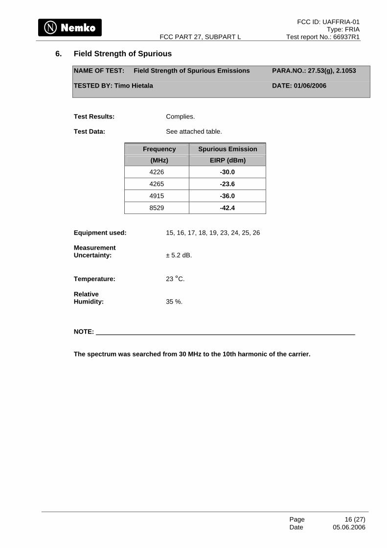
6. Field Strength of Spurious
NAME OF TEST: Field Strength of Spurious Emissions PARA.NO.: 27.53(g), 2.1053
TESTED BY: Timo Hietala DATE: 01/06/2006
Test Results: Complies. Test Data: See attached table.
Frequency Spurious Emission (MHz) EIRP (dBm)
4226 -30.0
4265 -23.6
4915 -36.0
8529 -42.4 Equipment used: 15, 16, 17, 18, 19, 23, 24, 25, 26 Measurement Uncertainty: ± 5.2 dB. Temperature: 23 °C. Relative Humidity: 35 %. NOTE: The spectrum was searched from 30 MHz to the 10th harmonic of the carrier.
FCC ID: UAFFRIA-01 Type: FRIA
FCC PART 27, SUBPART L Test report No.: 66937R1
Page 17 (27) Date
05.06.2006
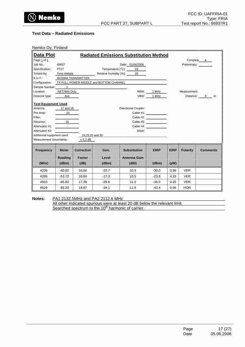
Test Data – Radiated Emissions Nemko Oy, Finland
Data Plot Radiated Emissions Substitution Method Page 1 of 1 Complete x Job No.: 69937 Date: 01/06/2006 Preliminary: Specification: PT27 Temperature (°C): 23 Tested By: Timo Hietala Relative Humidity (%): 35 E.U.T.: WCDMA TRANSMITTER Configuration: TX FULL POWER MIDDLE and BOTTOM CHANNEL Sample Number: 1 Location: NET/IMN Oulu RBW: 1 MHz Measurement Detector type: Ave VBW: 1 MHz Distance: 3 m
Test Equipment Used Antenna: 17 and 18 Directional Coupler: Pre-Amp: 24 Cable #1: Filter: Cable #2: Receiver: 16 Cable #3: Attenuator #1: - Cable #4: Attenuator #2: Mixer: Additional equipment used: 19,23,25 and 26 Measurement Uncertainty: ± 5.2 dB
Frequency Meter Correction
Gen. Substitution
EIRP EIRP Polarity Comments
Reading Factor
Level Antenna Gain
(MHz) (dBm) (dB) (dBm) (dBi) (dBm) (µW)
4226 -60.92 16.84 -23.7 10.5 -30.0 0.99 VER
4265 -53.72 16.84 -17.3 10.5 -23.6 4.33 VER
4915 -65.82 17.39 -29.6 11.0 -36.0 0.25 VER
8529 -85.20 19.87 -34.1 11.6 -42.4 0.06 HOR
Notes: PA1 2132.5MHz and PA2 2112.6 MHz
All other indicated spurious were at least 20 dB below the relevant limit. Searched spectrum to the 10th harmonic of carrier.
FCC ID: UAFFRIA-01 Type: FRIA
FCC PART 27, SUBPART L Test report No.: 66937R1
Page 18 (27) Date
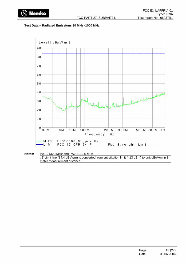
Test Data – Radiated Emissions 30 MHz -1000 MHz
0
1 0
2 0
3 0
4 0
5 0
6 0
7 0
8 0
9 0
L e v e l [ d Bµ V/ m ]
3 0 M 5 0 M 7 0 M 1 0 0 M 2 0 0 M 3 0 0 M 5 0 0 M 7 0 0 M 1 GF r e q u e n c y [ Hz ]
M ES HE0 1 0 6 0 6 _ 0 1 _ p r e PK L I M F CC 4 7 CF R 2 4 F F ie ld St r e n g h t L im it
Notes: PA1 2132.5MHz and PA2 2112.6 MHz . 1)Limit line (84.4 dBuV/m) is converted from substitution limit (–13 dBm) to unit dBuV/m in 3 meter measurement distance.
05.06.2006
FCC ID: UAFFRIA-01 Type: FRIA
FCC PART 27, SUBPART L Test report No.: 66937R1
Page 19 (27) Date
05.06.2006
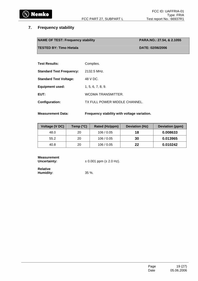
7. Frequency stability
NAME OF TEST: Frequency stability PARA.NO.: 27.54, & 2.1055
TESTED BY: Timo Hietala DATE: 02/06/2006
Test Results: Complies. Standard Test Frequency: 2132.5 MHz. Standard Test Voltage: 48 V DC. Equipment used: 1, 5, 6, 7, 8, 9. EUT: WCDMA TRANSMITTER. Configuration: TX FULL POWER MIDDLE CHANNEL. Measurement Data: Frequency stability with voltage variation.
Voltage (V DC) Temp (°C) Rated (Hz/ppm) Deviation (Hz) Deviation (ppm)
48.0 20 106 / 0.05 18 0.008633 55.2 20 106 / 0.05 30 0.013965 40.8 20 106 / 0.05 22 0.010242
Measurement Uncertainty: ± 0.001 ppm (± 2.0 Hz). Relative Humidity: 35 %.
FCC ID: UAFFRIA-01 Type: FRIA
FCC PART 27, SUBPART L Test report No.: 66937R1
Page 20 (27) Date
05.06.2006
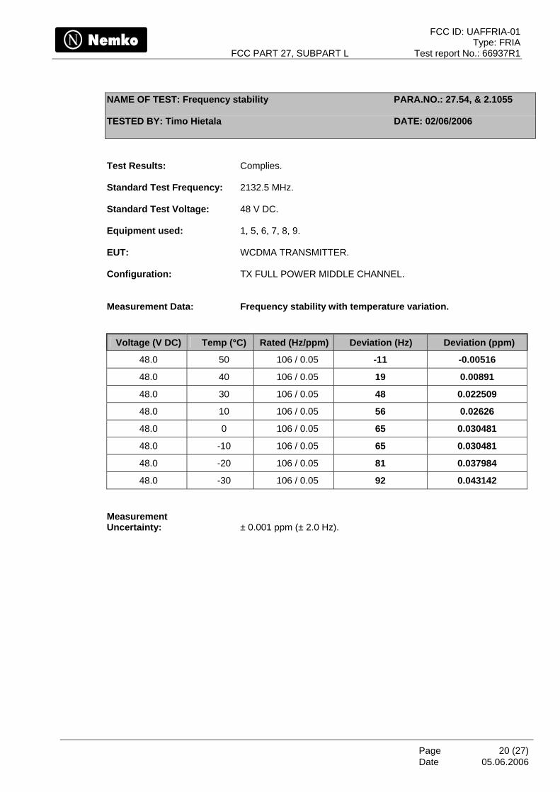
NAME OF TEST: Frequency stability PARA.NO.: 27.54, & 2.1055
TESTED BY: Timo Hietala DATE: 02/06/2006
Test Results: Complies. Standard Test Frequency: 2132.5 MHz. Standard Test Voltage: 48 V DC. Equipment used: 1, 5, 6, 7, 8, 9. EUT: WCDMA TRANSMITTER. Configuration: TX FULL POWER MIDDLE CHANNEL. Measurement Data: Frequency stability with temperature variation.
Voltage (V DC) Temp (°C) Rated (Hz/ppm) Deviation (Hz) Deviation (ppm)
48.0 50 106 / 0.05 -11 -0.00516
48.0 40 106 / 0.05 19 0.00891
48.0 30 106 / 0.05 48 0.022509
48.0 10 106 / 0.05 56 0.02626
48.0 0 106 / 0.05 65 0.030481
48.0 -10 106 / 0.05 65 0.030481
48.0 -20 106 / 0.05 81 0.037984
48.0 -30 106 / 0.05 92 0.043142 Measurement Uncertainty: ± 0.001 ppm (± 2.0 Hz).
FCC ID: UAFFRIA-01 Type: FRIA
FCC PART 27, SUBPART L Test report No.: 66937R1
Page 21 (27) Date
05.06.2006
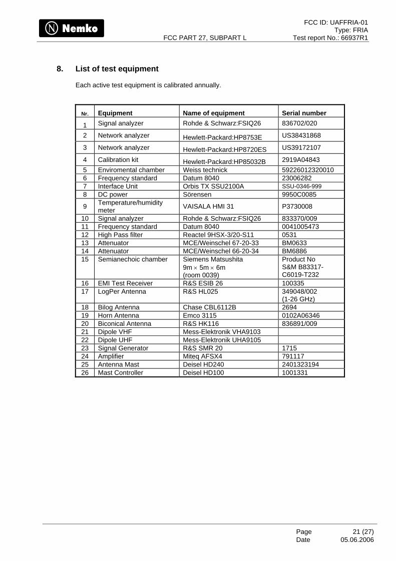
8. List of test equipment
Each active test equipment is calibrated annually.
Nr. Equipment Name of equipment Serial number
1 Signal analyzer Rohde & Schwarz:FSIQ26 836702/020
2 Network analyzer Hewlett-Packard:HP8753E US38431868
3 Network analyzer Hewlett-Packard:HP8720ES US39172107
4 Calibration kit Hewlett-Packard:HP85032B 2919A04843 5 Enviromental chamber Weiss technick 59226012320010 6 Frequency standard Datum 8040 23006282 7 Interface Unit Orbis TX SSU2100A SSU-0346-999 8 DC power Sörensen 9950C0085
9 Temperature/humidity meter VAISALA HMI 31 P3730008
10 Signal analyzer Rohde & Schwarz:FSIQ26 833370/009 11 Frequency standard Datum 8040 0041005473 12 High Pass filter Reactel 9HSX-3/20-S11 0531 13 Attenuator MCE/Weinschel 67-20-33 BM0633 14 Attenuator MCE/Weinschel 66-20-34 BM6886 15 Semianechoic chamber Siemens Matsushita
9m × 5m × 6m (room 0039)
Product No S&M B83317-C6019-T232
16 EMI Test Receiver R&S ESIB 26 100335 17 LogPer Antenna R&S HL025 349048/002
(1-26 GHz) 18 Bilog Antenna Chase CBL6112B 2694 19 Horn Antenna Emco 3115 0102A06346 20 Biconical Antenna R&S HK116 836891/009 21 Dipole VHF Mess-Elektronik VHA9103 22 Dipole UHF Mess-Elektronik UHA9105 23 Signal Generator R&S SMR 20 1715 24 Amplifier Miteq AFSX4 791117 25 Antenna Mast Deisel HD240 2401323194 26 Mast Controller Deisel HD100 1001331
FCC ID: UAFFRIA-01 Type: FRIA
FCC PART 27, SUBPART L Test report No.: 66937R1
Page 22 (27) Date
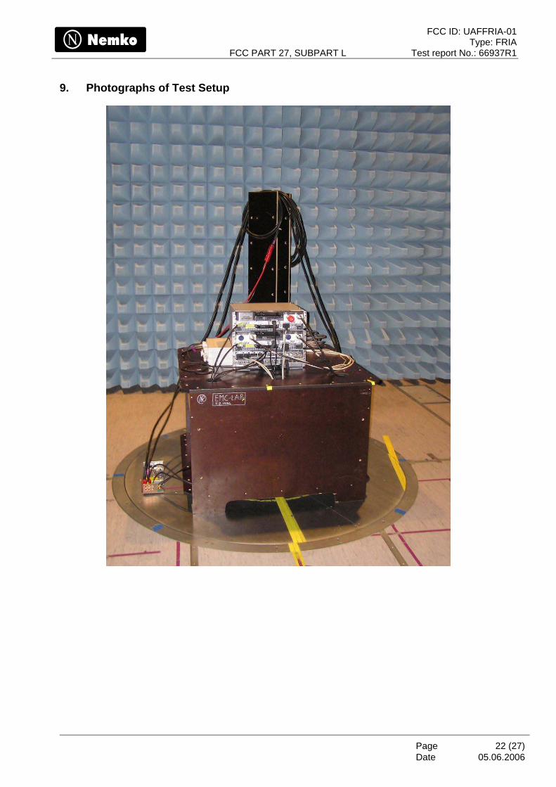
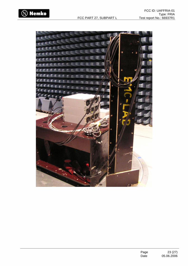
9. Photographs of Test Setup
05.06.2006
FCC ID: UAFFRIA-01 Type: FRIA
FCC PART 27, SUBPART L Test report No.: 66937R1
Page 23 (27) Date
05.06.2006
FCC ID: UAFFRIA-01 Type: FRIA
FCC PART 27, SUBPART L Test report No.: 66937R1
Page 24 (27) Date
05.06.2006
10. ANNEX A, TEST DETAILS
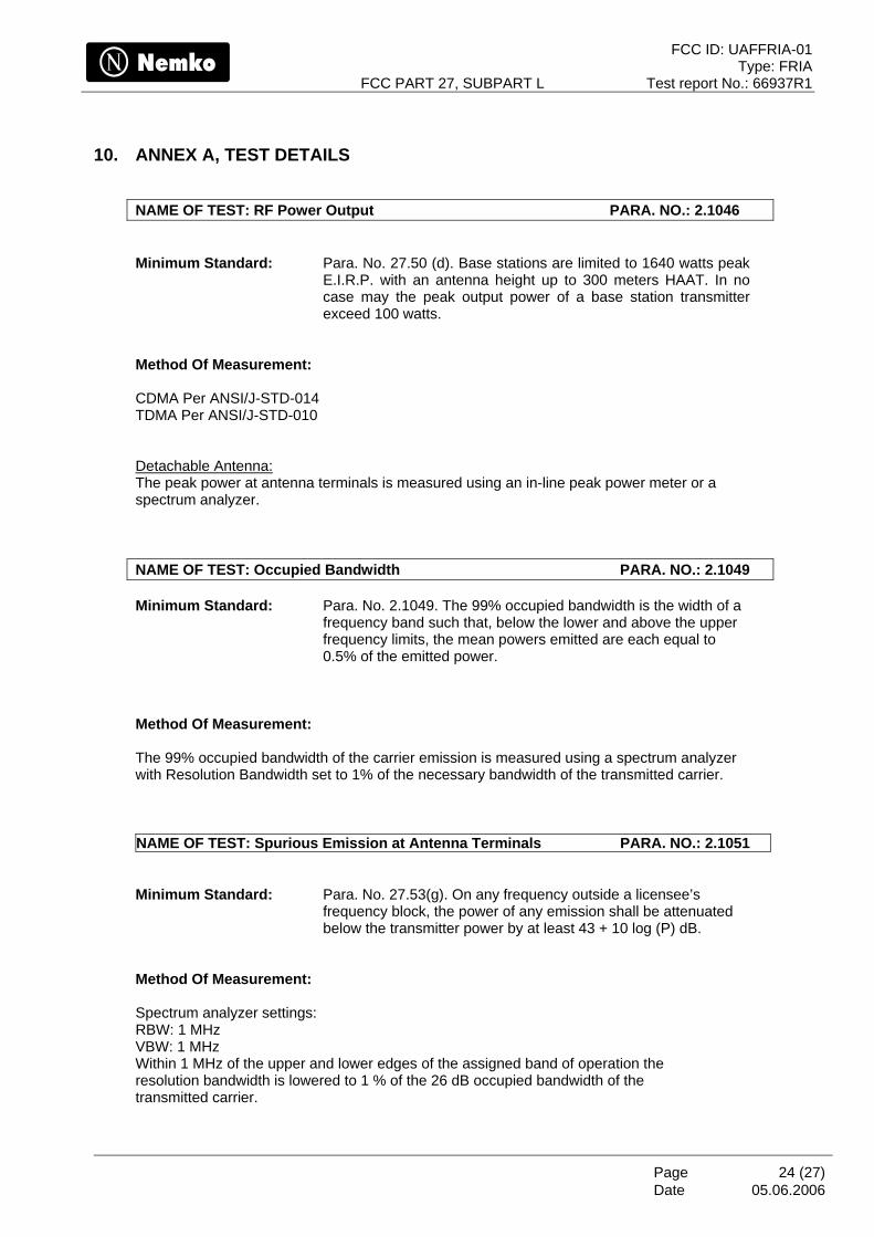
NAME OF TEST: RF Power Output PARA. NO.: 2.1046 Minimum Standard: Para. No. 27.50 (d). Base stations are limited to 1640 watts peak
E.I.R.P. with an antenna height up to 300 meters HAAT. In no case may the peak output power of a base station transmitter exceed 100 watts.
Method Of Measurement: CDMA Per ANSI/J-STD-014 TDMA Per ANSI/J-STD-010 Detachable Antenna: The peak power at antenna terminals is measured using an in-line peak power meter or a spectrum analyzer. NAME OF TEST: Occupied Bandwidth PARA. NO.: 2.1049 Minimum Standard: Para. No. 2.1049. The 99% occupied bandwidth is the width of a
frequency band such that, below the lower and above the upper frequency limits, the mean powers emitted are each equal to 0.5% of the emitted power.
Method Of Measurement:
The 99% occupied bandwidth of the carrier emission is measured using a spectrum analyzer with Resolution Bandwidth set to 1% of the necessary bandwidth of the transmitted carrier. NAME OF TEST: Spurious Emission at Antenna Terminals PARA. NO.: 2.1051 Minimum Standard: Para. No. 27.53(g). On any frequency outside a licensee’s
frequency block, the power of any emission shall be attenuated below the transmitter power by at least 43 + 10 log (P) dB.
Method Of Measurement: Spectrum analyzer settings: RBW: 1 MHz VBW: 1 MHz Within 1 MHz of the upper and lower edges of the assigned band of operation the resolution bandwidth is lowered to 1 % of the 26 dB occupied bandwidth of the transmitted carrier.
FCC ID: UAFFRIA-01 Type: FRIA
FCC PART 27, SUBPART L Test report No.: 66937R1
Page 25 (27) Date
05.06.2006
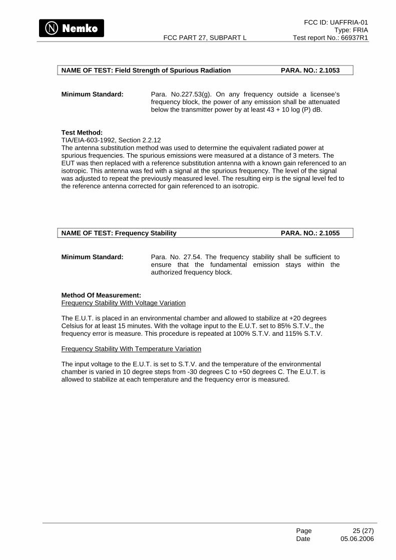
NAME OF TEST: Field Strength of Spurious Radiation PARA. NO.: 2.1053 Minimum Standard: Para. No.227.53(g). On any frequency outside a licensee’s
frequency block, the power of any emission shall be attenuated below the transmitter power by at least 43 + 10 log (P) dB.
Test Method: TIA/EIA-603-1992, Section 2.2.12 The antenna substitution method was used to determine the equivalent radiated power at spurious frequencies. The spurious emissions were measured at a distance of 3 meters. The EUT was then replaced with a reference substitution antenna with a known gain referenced to an isotropic. This antenna was fed with a signal at the spurious frequency. The level of the signal was adjusted to repeat the previously measured level. The resulting eirp is the signal level fed to the reference antenna corrected for gain referenced to an isotropic. NAME OF TEST: Frequency Stability PARA. NO.: 2.1055 Minimum Standard: Para. No. 27.54. The frequency stability shall be sufficient to
ensure that the fundamental emission stays within the authorized frequency block.
Method Of Measurement: Frequency Stability With Voltage Variation The E.U.T. is placed in an environmental chamber and allowed to stabilize at +20 degrees Celsius for at least 15 minutes. With the voltage input to the E.U.T. set to 85% S.T.V., the frequency error is measure. This procedure is repeated at 100% S.T.V. and 115% S.T.V. Frequency Stability With Temperature Variation The input voltage to the E.U.T. is set to S.T.V. and the temperature of the environmental chamber is varied in 10 degree steps from -30 degrees C to +50 degrees C. The E.U.T. is allowed to stabilize at each temperature and the frequency error is measured.
FCC ID: UAFFRIA-01 Type: FRIA
FCC PART 27, SUBPART L Test report No.: 66937R1
Page 26 (27) Date
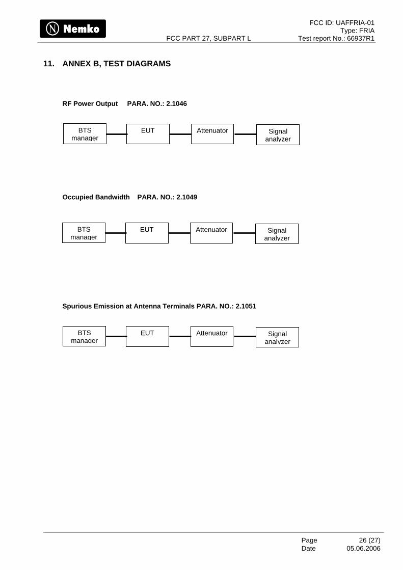
11. ANNEX B, TEST DIAGRAMS
RF Power Output PARA. NO.: 2.1046
Attenuator EUT
Signal analyzer
BTS manager
Occupied Bandwidth PARA. NO.: 2.1049
Attenuator EUT
Signal analyzer
BTS manager
Spurious Emission at Antenna Terminals PARA. NO.: 2.1051
Attenuator EUT
Signal analyzer
BTS manager
05.06.2006
FCC ID: UAFFRIA-01 Type: FRIA
FCC PART 27, SUBPART L Test report No.: 66937R1
Page 27 (27) Date
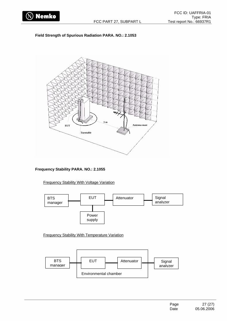
Field Strength of Spurious Radiation PARA. NO.: 2.1053
3 mEUT
Turntable
Antenna mast
Frequency Stability PARA. NO.: 2.1055
Frequency Stability With Voltage Variation
Attenuator EUT
BTS manager
Power supply
Signal analyzer
Frequency Stability With Temperature Variation
Attenuator EUT
Signal analyzer
BTS manager
Environmental chamber
05.06.2006