Embed Size (px)
Citation preview
NASA / TMm2000-210025
Noise Reduction Potential of Large,
Over-the-Wing Mounted, Advanced
Turbofan Engines
Jeffrey J. BertonGlenn Research Center, Cleveland, Ohio
April 2000
The NASA STI Program Office... in Profile
Since its founding, NASA has been dedicated to
the advancement of aeronautics and spacescience. The NASA Scientific and Technical
Information (STI) Program Office plays a key part
in helping NASA maintain this important role.
The NASA STI Program Office is operated by
Langley Research Center, the Lead Center forNASA's scientific and technical information. The
NASA STI Program Office provides access to the
NASA STI Database, the largest collection ofaeronautical and space science STI in the world.
The Program Office is also NASA's insttufional
mechanism for disseminating the results of itsresearch and development activities. These results
are published by NASA in the NASA STI Report
Series, which includes the following report types:
TECHNICAL PUBLICATION. Reports ofcompleted research or a major significant
phase of research that present the results ofNASA programs and include extensive data
or theoretical analysis. Includes compilationsof significant scientific and technical data and
information deemed to be of continuing
reference value. NASA's counterpart of peer-reviewed formal professional papers but
has less stringent limitations on manuscriptlength and extent of graphic presentations.
TECHNICAL MEMORANDUM. Scientific
and technical findings that are preliminary or
of specialized interest, e.g., quick releasereports, working papers, and bibliographiesthat contain minimal annotation. Does not
contain extensive analysis.
CONTRACTOR REPORT. Scientific and
technical findings by NASA-sponsoredcontractors and grantees.
CONFERENCE PUBLICATION. Collected
papers from scientific and technicalconferences, symposia, seminars, or other
meetings sponsored or cosponsored byNASA.
SPECIAL PUBLICATION. Scientific,
technical, or historical information from
NASA programs, projects, and missions,often concerned with subjects havingsubstantial public interest.
TECHNICAL TRANSLATION. English-
language translations of foreign scientificand technical material pertinent to NASA'smission.
Specialized services that complement the STI
Program Office's diverse offerings includecreating custom thesauri, building customized
data bases, organizing and publishing researchresults.., even providing videos.
For more information about the NASA STI
Program Office, see the following:
• Access the NASA STI Program Home Page
at http://www.sti.nasa.gov
• E-mail your question via the Internet [email protected]
• Fax your question to the NASA Access
Help Desk at (301) 621-0134
• Telephone the NASA Access Help Desk at(301) 621-0390
Write to:
NASA Access Help DeskNASA Center for AeroSpace Information7121 Standard Drive
Hanover, MD 21076
NASA / TMm2000-210025
Noise Reduction Potential of Large,
Over-the-Wing Mounted, Advanced
Turbofan Engines
Jeffrey J. Berton
Glenn Research Center, Cleveland, Ohio
Prepared for the
14th International Symposium on Air Breathing Engines
sponsored by the International Society. for Air Breathing Engines
Florence, Italy, September 5-10, 1999
National Aeronautics and
Space Administration
Glenn Research Center
April 2000
Acknowledgments
Thanks to David Elliott of NASA Glenn for providing the experimental Low Noise Fan data used in this study.
Trade names or manufacturers' names are used in this report for
identification only. This usage does not constitute an official
endorsement, either expressed or implied, by the National
Aeronautics and Space Administration.
NASA Center for Aerospace Information7121 Standard Drive
Hanover, MD 21076Price Code: A03
Available from
National Technical Information Service
5285 Port Royal Road
Springfield, VA 22100Price Code: A03
Noise Reduction Potential of Large, Over-the-Wing Mounted,Advanced Turbofan Engines
Jeffrey J. Berton*National Aeronautics and Space Administration
Glenn Research Center
Cleveland, Ohio
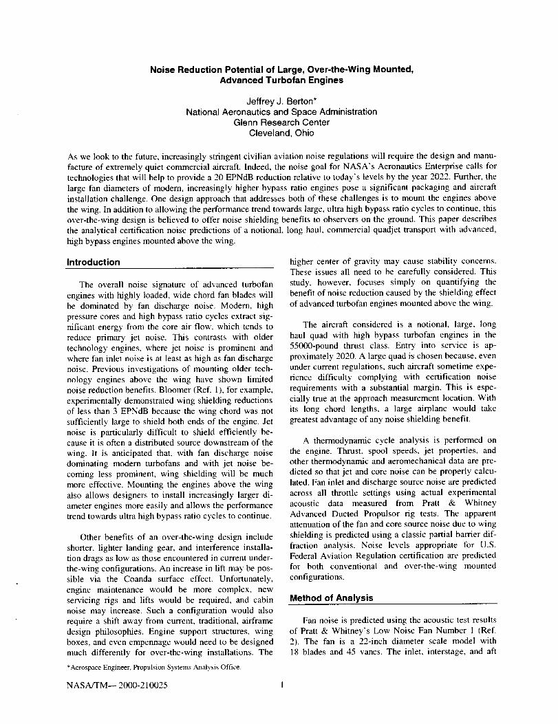
As we look to the future, increasingly stringent civilian aviation noise regulations will require the design and manu-facture of extremely quiet commercial aircraft. Indeed, the noise goal for NASA's Aeronautics Enterprise calls for
technologies that will help to provide a 20 EPNdB reduction relative to today's levels by the year 2022. Further, thelarge fan diameters of modem, increasingly higher bypass ratio engines pose a significant packaging and aircraft
installation challenge. One design approach that addresses both of these challenges is to mount the engines above
the wing. In addition to allowing the performance trend towards large, ultra high bypass ratio cycles to continue, thisover-the-wing design is believed to offer noise shielding benefits to observers on the ground. This paper describes
the analytical certification noise predictions of a notional, long haul, commercial quadjet transport with advanced,high bypass engines mounted above the wing.
Introduction
The overall noise signature of advanced turbofan
engines with highly loaded, wide chord fan blades willbe dominated by fan discharge noise. Modem, high
pressure cores and high bypass ratio cycles extract sig-nificant energy from the core air flow, which tends to
reduce primary jet noise. This contrasts with oldertechnology engines, where jet noise is prominent and
where fan inlet noise is at least as high as fan dischargenoise. Previous investigations of mounting older tech-
nology engines above the wing have shown limitednoise reduction benefits. Bloomer (Ref. I ), for example,
experimentally demonstrated wing shielding reductionsof less than 3 EPNdB because the wing chord was not
sufficiently large to shield both ends of the engine. Jetnoise is particularly difficult to shield efficiently be-cause it is often a distributed source downstream of the
wing. It is anticipated that, with fan discharge noise
dominating modern turbofans and with jet noise be-coming less prominent, wing shielding will be much
more effective. Mounting the engines above the wingalso allows designers to install increasingly larger di-
ameter engines more easily and allows the performancetrend towards ultra high bypass ratio cycles to continue.
Other benefits of an over-the-wing design include
shorter, lighter landing gear, and interference installa-tion drags as low as those encountered in current under-the-wing configurations. An increase in lift may be pos-
sible via the Coanda surface effect. Unfortunately,engine maintenance would be more complex, new
servicing rigs and lifts would be required, and cabin
noise may increase. Such a configuration would alsorequire a shift away from current, traditional, airframedesign philosophies. Engine support structures, wing
boxes, and even empennage would need to be designedmuch differently for over-the-wing installations. The
*Aerospace Engineer, Propulsion Systems Analysis Office.
higher center of gravity may cause stability concerns.These issues all need to be carefully considered. Thisstudy, however, focuses simply on quantifying the
benefit of noise reduction caused by the shielding effect
of advanced turbofan engines mounted above the wing.
The aircraft considered is a notional, large, long
haul quad with high bypass turbofan engines in the
55000-pound thrust class. Entry into service is ap-proximately 2020. A large quad is chosen because, even
under current regulations, such aircraft sometime expe-rience difficulty complying with certification noise
requirements with a substantial margin. This is espe-cially true at the approach measurement location. With
its long chord lengths, a large airplane would takegreatest advantage of any noise shielding benefit.
A thermodynamic cycle analysis is performed on
the engine. Thrust, spool speeds, jet properties, andother thermodynamic and aeromechanicai data are pre-dicted so that jet and core noise can be properly calcu-
lated. Fan inlet and discharge source noise are predictedacross all throttle settings using actual experimental
acoustic data measured from Pratt & Whitney
Advanced Ducted Propulsor rig tests. The apparentattenuation of the fan and core source noise due to wing
shielding is predicted using a classic partial barrier dif-
fraction analysis. Noise levels appropriate for U.S.
Federal Aviation Regulation certification are predictedfor both conventional and over-the-wing mounted
configurations.
Method of Analysis
Fan noise is predicted using the acoustic test resultsof Pratt & Whitney's Low Noise Fan Number 1 (Ref.
2). The fan is a 22-inch diameter scale model with18 blades and 45 vanes. The inlet, interstage, and aft
NASA/TM-- 2000-210025 1
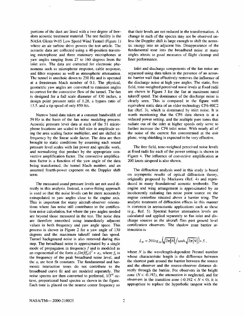
portionsoftheductarelinedwithatwodegreeof free-domacoustictreatmentmaterial.Thetestfacilityis theNASAGlenn9×15LowSpeedWindTunnel(Figure1)whereanairturbinedrivepowersthetestarticle.Theacousticdataarecollectedusinga48-positiontravers-ing microphoneandthreestationarymicrophonesatyawanglesrangingfrom27to 160degreesfromtheinletaxis.Thedataarecorrectedfor electronicphe-nomenasuchasmicrophoneresponse,cableresponse,andfilterresponseaswellasatmosphericattenuation.Thetunnelisanechoicdownto250Hzandisoperatedat a freestreamMachnumberof 0.1.Thephysical,geometricyawanglesareconvertedtoemissionanglestocorrectfortheconvectiveflowofthetunnel.Thefanis designedfor afull scalediameterof 130inches,adesignpointpressureratioof 1.28,a bypassratioof13.5,andatipspeedofonly850ft/s.
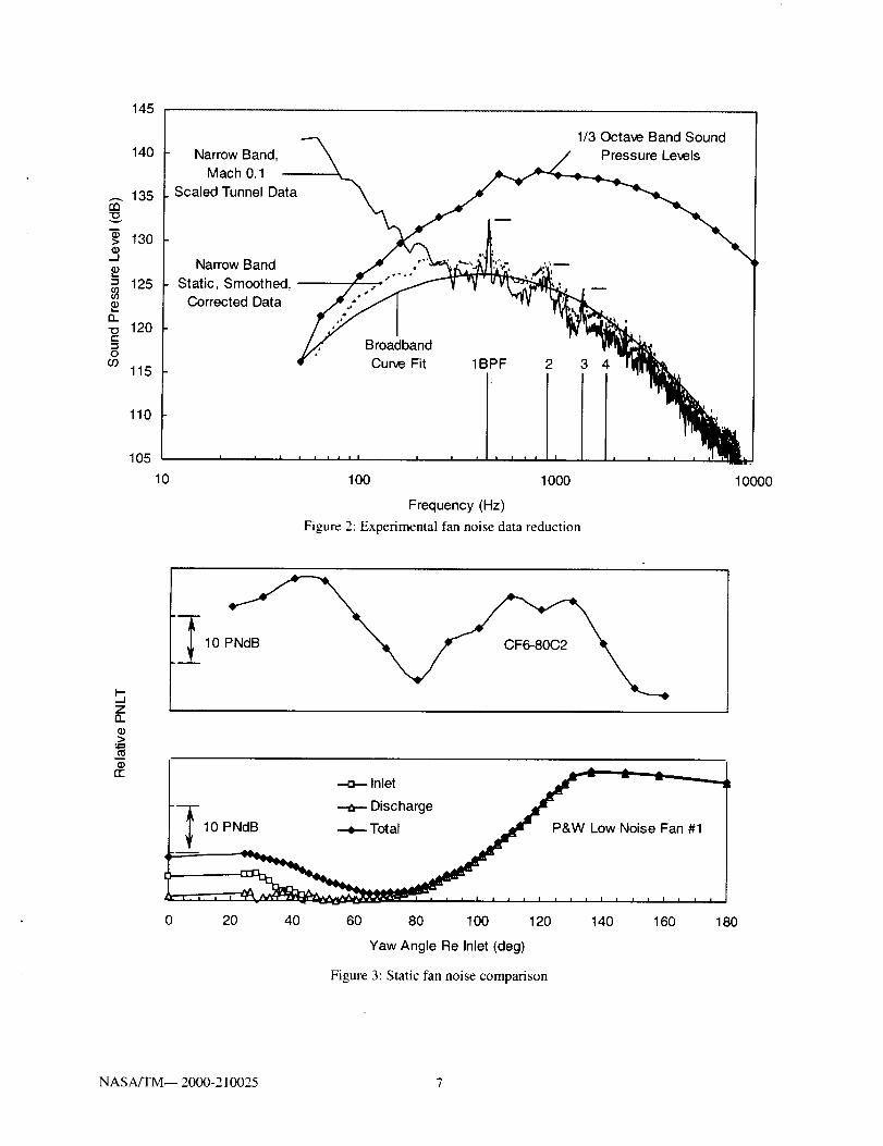
Narrowbanddatatakenataconstantbandwidthof59Hzis thebasisof thefannoisemodelingprocess.Acoustic pressure level data at each of the 51 micro-phone locations are scaled to full size in amplitude us-ing the area scaling factor multiplier, and are shifted in
frequency by the linear scale factor. The data are then
brought to static conditions by assuming each soundpressure level scales with fan power and specific work,
and normalizing that product by the appropriate con-vective amplification factor. The convective amplifica-
tion factor is a function of the yaw angle of the databeing transformed, the tunnel Mach number, and an
assumed fourth-power exponent on the Doppler shiftterm.
The measured sound pressure levels are not used di-
rectly in this analysis. Instead, a curve-fitting approachis used so that the noise levels can be more accurately
extrapolated to yaw angles close to the engine axis.This is important for many aircraft-observer orienta-tions where fan noise still contributes to the certifica-
tion noise calculation, but where the yaw angles neededare beyond those measured in the test. The noise data
are therefore smoothed using immediately adjacentvalues in both frequency and yaw angle space. This
process is shown in Figure 2 for a yaw angle of 130degrees and the maximum takeoff rated fan speed.
Tunnel background noise is also removed during thisstep. The broadband noise is approximated by a single
mode of propagation in frequency f and is modeled as
an exponential of the form al[ln(f/fp)]'- + a,, where fp isthe frequency of the peak broadband noise level, andthe ai are best fit constants. The fundamental and har-monic interaction tones do not contribute to the
broadband curve fit and are modeled separately. Thenoise spectra are then converted to preferred, 1/3 rd oc-
tave, proportional band spectra as shown in the figure.
Each tone is placed on the nearest center frequency so
that their levels are not reduced in the transformation. A
change in each of the spectra may not be observed un-less the Doppler shift is large enough to shift the acous-
tic energy into an adjacent bin. Disappearance of thefundamental tone into the broadband noise at many
angles attests to good measures of flight cleanup andliner performance.
Inlet and discharge components of the fan noise are
separated using data taken in the presence of an acous-tic barrier wall that effectively removes the influence of
the discharge noise at high yaw angles. The static, freefield, tone-weighted perceived noise levels at fixed radii
are shown in Figure 3 for the fan at maximum ratedtakeoff speed. The dominance of the discharge noise is
clearly seen. This is compared in the figure withequivalent static data of an older technology CF6-80C2
fan (Ref. 3), which is dominated by inlet noise. It isworth mentioning that the CF6 data shown is at a
reduced power setting, and the multiple pure tones thatradiate out of the inlet at higher speeds only serve to
further increase the CF6 inlet noise. With nearly all ofthe noise of the current fan concentrated at the exit
plane, wing shielding is expected to be very effective.
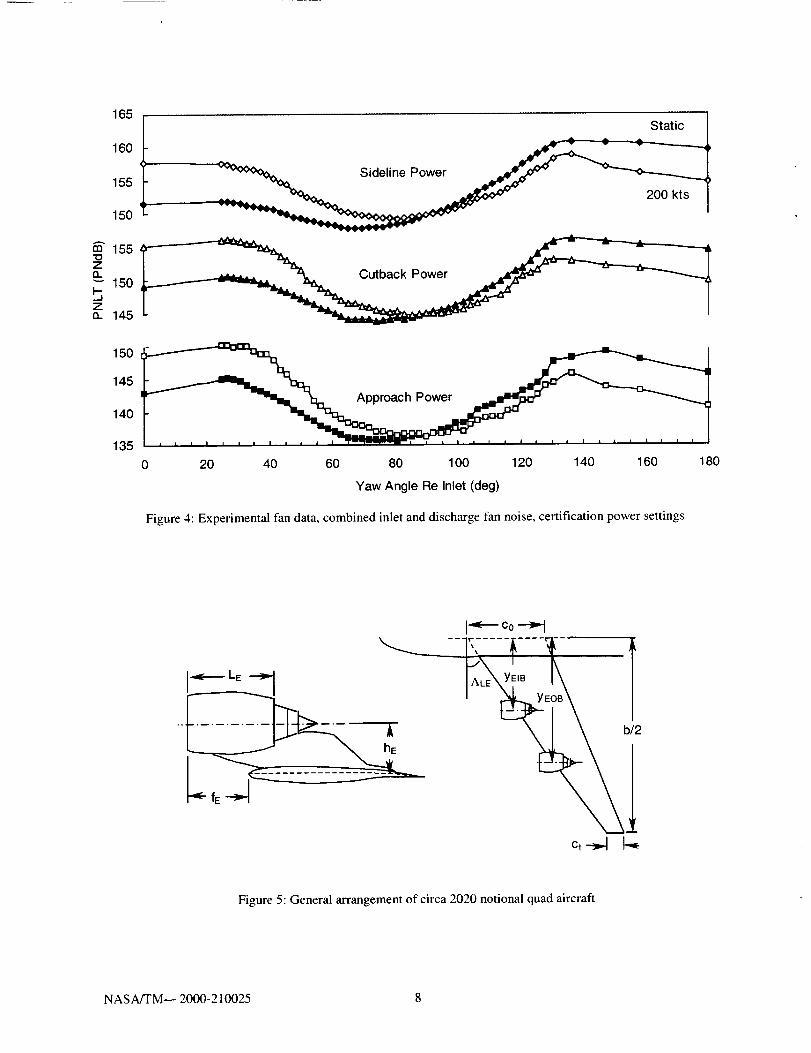
The free field, tone-weighted perceived noise levelsat fixed radii for each of the power settings is shown in
Figure 4. The influence of convective amplification at200 knots airspeed is also shown.
The diffraction analysis used in this study is based
on asymptotic results of optical diffraction theory,originally proposed by Maekawa (Ref. 4) and repro-duced in many foundational acoustic textbooks. The
engine and wing arrangement is approximated by an
incoherently radiating fan noise point source on theengine centerline situated above a barrier wing. Theanalytic treatment of diffraction effects in this manner
is common in aeroacoustic applications such as these
(e.g., Ref. 5). Spectral barrier attenuation levels arecalculated and applied separately to fan inlet and dis-charge sources as the aircraft flies past ground levelcertification observers. The shadow zone bamer at-
tenuation is
LR = 2Olog_o 2(_f_lNI/tanh 2_])+ 5 ,
where N is the wavelength-dependent Fresnel numberwhose characteristic length is the difference between
the shortest path around the barrier between the sourceand the observer and the source-observer distance di-
rectly through the barrier. For observers in the brightzone (N < -0.192), the attenuation is neglected, and for
observers in the transition zone (-0.192 < N < 0), it is
appropriate to replace the hyperbolic tangent with the
NASA/TM-- 2000-210025 2
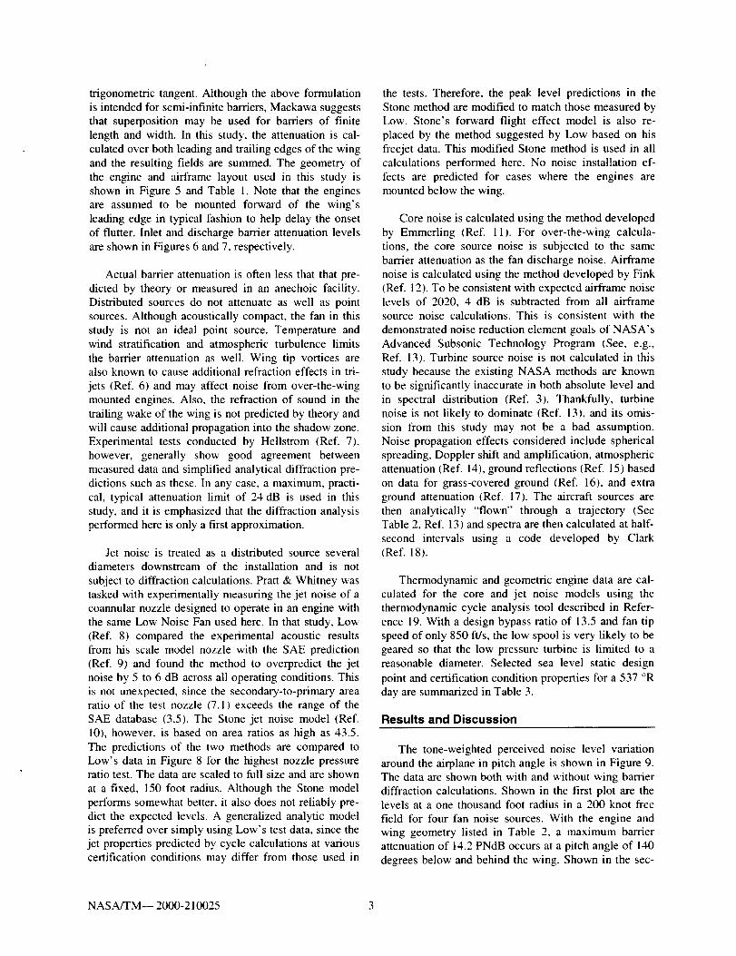
trigonometrictangent.Althoughthe above formulation
is intended for semi-infinite barriers, Maekawa suggeststhat superposition may be used for barriers of finite
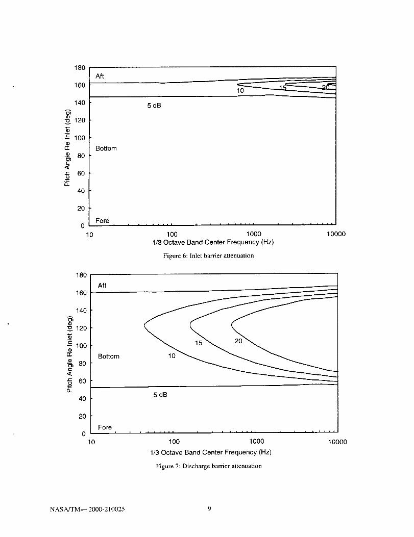
length and width. In this study, the attenuation is cal-culated over both leading and trailing edges of the wing
and the resulting fields are summed. The geometry ofthe engine and airframe layout used in this study is
shown in Figure 5 and Table 1. Note that the enginesare assumed to be mounted forward of the wing's
leading edge in typical fashion to help delay the onsetof flutter. Inlet and discharge barrier attenuation levels
are shown in Figures 6 and 7, respectively.
Actual bamer attenuation is often less that that pre-
dicted by theory or measured in an anechoic facility.Distributed sources do not attenuate as well as point
sources. Although acoustically compact, the fan in thisstudy is not an ideal point source. Temperature and
wind stratification and atmospheric turbulence limitsthe barrier attenuation as well. Wing tip vortices arealso known to cause additional refraction effects in tri-
jets (Ref. 6) and may affect noise from over-the-wing
mounted engines. Also, the refraction of sound in thetrailing wake of the wing is not predicted by theory and
will cause additional propagation into the shadow zone.Experimental tests conducted by Hellstrom (Ref. 7),
however, generally show good agreement betweenmeasured data and simplified analytical diffraction pre-
dictions such as these. In any case, a maximum, practi-cal, typical attenuation limit of 24 dB is used in this
study, and it is emphasized that the diffraction analysisperformed here is only a first approximation.
Jet noise is treated as a distributed source several
diameters downstream of the installation and is not
subject to diffraction calculations. Pratt & Whitney wastasked with experimentally measuring the jet noise of acoannular nozzle designed to operate in an engine with
the same Low Noise Fan used here. In that study, Low(Ref. 8) compared the experimental acoustic results
from his scale model nozzle with the SAE prediction(Ref. 9) and found the method to overpredict the jet
noise by 5 to 6 dB across all operating conditions. Thisis not unexpected, since the secondary-to-primary area
ratio of the test nozzle (7.1) exceeds the range of theSAE database (3.5). The Stone jet noise model (Ref.
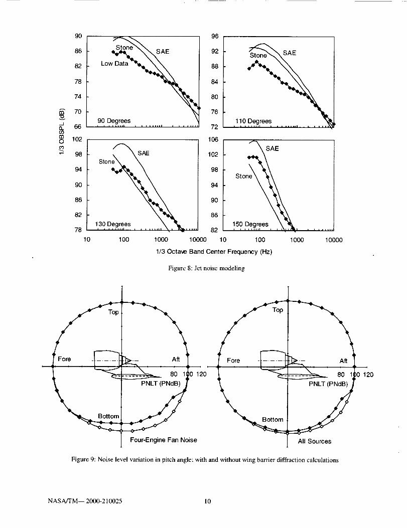
10), however, is based on area ratios as high as 43.5.The predictions of the two methods are compared to
Low's data in Figure 8 for the highest nozzle pressureratio test. The data are scaled to full size and are shown
at a fixed, 150 foot radius. Although the Stone modelperforms somewhat better, it also does not reliably pre-dict the expected levels. A generalized analytic model
is preferred over simply using Low's test data, since thejet properties predicted by cycle calculations at various
certification conditions may differ from those used in
the tests. Therefore, the peak level predictions in theStone method are modified to match those measured by
Low. Stone's forward flight effect model is also re-placed by the method suggested by Low based on his
freejet data. This modified Stone method is used in allcalculations performed here. No noise installation ef-
fects are predicted for cases where the engines are
mounted below the wing.
Core noise is calculated using the method developed
by Emmerting (Ref. 11). For over-the-wing calcula-
tions, the core source noise is subjected to the samebarrier attenuation as the fan discharge noise. Airframe
noise is calculated using the method developed by Fink(Ref. 12). To be consistent with expected airframe noiselevels of 2020, 4 dB is subtracted from all airframesource noise calculations. This is consistent with the
demonstrated noise reduction element goals of NASA's
Advanced Subsonic Technology Program (See, e.g.,Ref. 13). Turbine source noise is not calculated in this
study because the existing NASA methods are knownto be significantly inaccurate in both absolute level and
in spectral distribution (Ref. 3). Thankfully, turbinenoise is not likely to dominate (Ref. 13), and its omis-sion from this study may not be a bad assumption.
Noise propagation effects considered include sphericalspreading, Doppler shift and amplification, atmospheric
attenuation (Ref. 14), ground reflections (Ref. 15) based
on data for grass-covered ground (Ref. 16), and extraground attenuation (Ref. 17). The aircraft sources are
then analytically "flown" through a trajectory (SeeTable 2, Ref. 13) and spectra are then calculated at half-
second intervals using a code developed by Clark(Ref. 18).
Thermodynamic and geometric engine data are cal-culated for the core and jet noise models using the
thermodynamic cycle analysis tool described in Refer-ence 19. With a design bypass ratio of 13.5 and fan tip
speed of only 850 ft/s, the low spool is very likely to be
geared so that the low pressure turbine is limited to areasonable diameter. Selected sea level static design
point and certification condition properties for a 537 °R
day are summarized in Table 3.
Results and Discussion
The tone-weighted perceived noise level variation
around the airplane in pitch angle is shown in Figure 9.The data are shown both with and without wing barrier
diffraction calculations. Shown in the first plot are thelevels at a one thousand foot radius in a 200 "knot free
field for four fan noise sources. With the engine and
wing geometry listed in Table 2, a maximum barrierattenuation of 14.2 PNdB occurs at a pitch angle of 140
degrees below and behind the wing. Shown in the sec-
NASA/TM-- 2000-210025 3
ondplotis thenoiselevelvariationwithall sourcesconsidered.Withnobarriercalculationsappliedto air-
frame and jet noise, the maximum shielding effect isreduced to only 9.2 PNdB at a pitch angle of 140 de-
grees. This limitation of the barrier effectiveness is a
result of the low noise signature of the study enginerelative to airframe noise and becomes important in the
certification noise predictions described below.
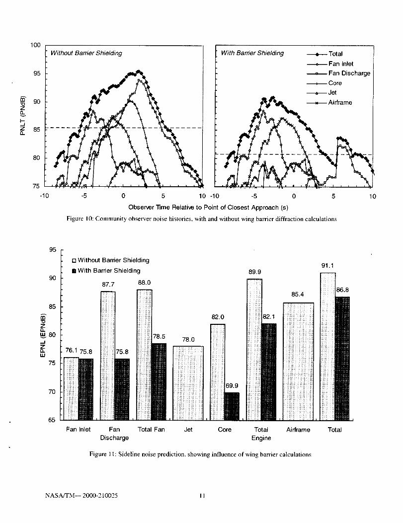
The airplane is analytically flown through its tra-jectory as described earlier and noise histories are cal-culated for each certification observer. Sample noise
histories are shown in Figure 10 for the community
observer. Shown in the first plot are the histories with-out wing barrier diffraction calculations. As expected,
the trace is dominated by fan discharge noise. The low
specific thrust of the engine is evident from the ex-tremely low levels of jet noise. Shown in the second
plot are the histories when the wing barrier is consid-ered. Also as expected, the wing effectively eliminatesthe fan discharge and core noise relative to the otherunshielded noise sources. In the shielded case, fan inletand airframe noise dominate the trace. Fan inlet noise is
not shielded well for a flyover observer with the ge-ometry considered. Fan discharge noise rises again later
in the trace as the observer quickly emerges from thetransition zone, but it does not contribute significantly
to the effective perceived noise level. The unsteadinessseen in the traces is due mainly to irregularities in the
spectra introduced by ground reflection calculations andaccentuated by the tone penalty component of the noisemetric. The noise histories for the other certification
observers are similar and are not shown.
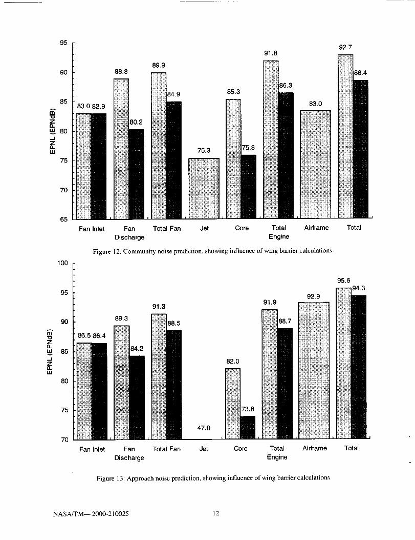
Effective perceived noise levels for the sideline,
community, and approach observers are shown in Fig-ures 11 through 13, respectively. Contributions of theindividual noise sources and the effectiveness of the
wing barrier are shown. 90 and 95 EPNdB contoursaround the runway are shown in Figure 14. Mounting
the engines above the wing results in a reduction of the
95 EPNdB footprint from 0.96 to 0.57 square miles. Incertification parlance, the airplane in this study is 44.5cumulative EPNdB below Stage 3 regulations, 9.9 cu-
mulative EPNdB of which may be attributed to wing
barrier shielding. This compares favorably with thecertification noise levels of current large quads, whichare approximately 10 cumulative EPNdB below Stage 3
regulations (Ref. 13).
Conclusions
The noise of advanced turbofan engines is shown tobe effectively shielded in an over-the-wing mounted
installation. Making this possible is the dominance ofthe fan discharge noise and the relatively low levels of
distributed jet noise. Mounting the engines above thewing may also result in other forms of noise reductionnot considered in this study. The enhancement of low
frequency boundary layer noise due to the entrainment
of air between the wing and the jet can often be sub-stantial (Ref. 20). Mounting the engines above the wingwould eliminate this additional noise source and would
also prevent the wing from serving as a high frequency
noise reflector. Although expensive, ground testing andin-flight measurements may be the only way to accu-
rately measure shielding attenuation of a modern enginein a proper, full scale operating environment with real-istic sources.
The low fan speed, low specific thrust engine con-sidered here is remarkably quiet. Airframe noise is
therefore predicted to become a significant noise source
for the conceptual long haul quad aircraft studied. Thisconclusion is reached despite the airframe noise reduc-
tion levels assumed in this study, and it is especiallytrue when the engine noise is reduced further via thewing shielding effect. Airframe noise has often beencalled the lower bound of certification noise, and it is
certainly the case in this study. Airframe noise reduc-tions are possible, however, and the airframe noise
technologies assumed here may eventually need to beimplemented on future aircraft.
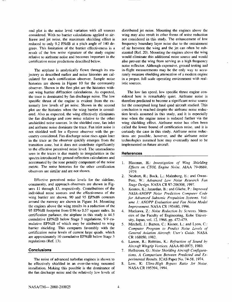
References
1. Bloomer, H.: Investigation of Wing ShieldingEffects on CTOL Engine Noise. AIAA 79-0669,1979.
2. Neubert, R.; Bock, L., Malmborg, E.; and Owen-Peer, W.: Advanced Low Noise Research Fan
Stage Design. NASA CR 97-206308, 1997.3. Kontos, K.; Janardan, B.: and Gliebe, P.: Improved
NASA-ANOPP Noise Prediction Computer Codefor Advanced Subsonic Propulsion Systems. Vol-ume 1." ANOPP Evaluation and Fan Noise Model
Improvement. NASA CR 195480, 1996.4. Maekawa, Z.: Noise Reduction by Screens. Mem-
oirs of the Faculty of Engineering, Kobe Univer-sity, Japan, vol. 12, 1966, pp. 472-479.
5. Mitchell, J.: Barton, C.: Kisner, L.: and Lyon, C.:
Computer Program to Predict Noise Levels ofGeneral Aviation Aircraft." User's Guide. NASACR 168050, 1982.
6. Larson, R.; Robbins, K.: Refraction of Sound by
Aircraft Wingtip Vortices. AIAA-80-0975, 1980.7. Hellstrom, G.: Noise Shielding Aircraft Configura-
tions, A Comparison Between Predicted and Ex-perimental Results. ICAS Paper No. 74-58, 1974.
8. Low, K: Ultra-High Bypass Ratio Jet Noise.NASA CR 195394, 1994.
NASA/TM-- 2000-210025 4
9. Proposed Coaxial Jet Noise Prediction Pivcedure.
Aerospace Recommended Practice 876, Rev. C,1975, SAE.
10. Stone, J.: An Improved Prediction Method ,for
Noise Generated by Conventional Profile CoaxialJets. NASA TM 82712, 1981.
11. Emmerling, J.: Kazin, S.: and Matta, R.: Core En-
gine Noise Control Program. Volume 111, Supple-ment 1 - Prediction Methods. FAA-RD-74-125, III-I, March 1976.
12. Fink, M.: Ai_.rame Noise Prediction Method.FAA-RD-77-29, March, 1977.
13. Kumasaka, H.: Martinez, M.; and Weir, D.: Deft-
nition of 1992 Technology Aircraft Noise Levelsand the Methodology .fop"Assessing Airplane Noise
hnpact of Component Noise Reduction Concepts.NASA CR 198298, 1996.
14. Standard Values of Atmospheric Absorption as a
Function of Temperature and Humidity. AerospaceRecommended Practice 866, 1964, SAE.
15. Putnam, T.: Review of Aircraft Noise Propagation.NASA TM-X-56033, 1975.
16. Delaney, M.: and Bazley, E.: Acoustical Propertiesof Fibrous Absorbent Materials. Applied Acous-
tics, Vol 3, No 2, Apr 1970, pp 105-116.
17. Method for Calculating the Attenuation of AircraftGround to Ground Noise Propagation during
Takeoff and Landing. Aerospace Information Re-port 923, Aug. 15, 1966, SAE.
18. Clark, B.: Computer Program to Predict AircraftNoise Levels. NASA TP 1913, 1981.
19. Klann, J.: and Snyder, C.: NEPP ProgrammersManual, Volume I." Technical Description. NASATM 106575, 1994.
20. Wang, M.: Wing Effect on Jet Noise Propagation.AIAA Paper No. 80-1047, 1980.
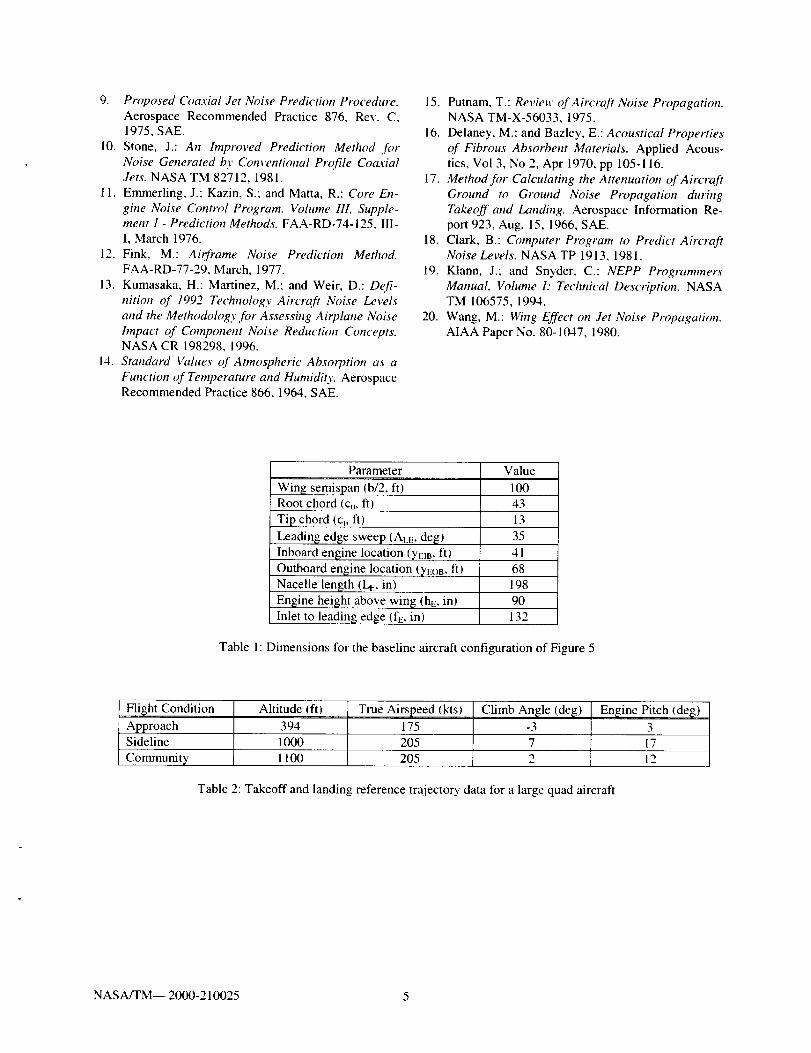
Parameter Value
100Wing semispan (b/2, ft)Root chord (Co, ft) 43
Tip chord (c,, fl) 13
Leading edge sweep (ACE, deg)
Inboard engine location (yEIB, ft)
Outboard engine location (yEOB, ft)
Nacelle length (L_:, in)Engine height above wing (hE, in)
Inlet to leading edge (fE, in)
35
41
68
198
90
132
Table 1: Dimensions for the baseline aircraft configuration of Figure 5
Flight ConditionApproach
Altitude (fl)
Community
True Airspeed (kts)175
Climb An_le (de_)-3394
Sideline 1000 205 7 17
I 100 205 2 12
Engine Pitch (de_)3
Table 2: Takeoff and landing reference trajectory data for a large quad aircraft
NASA/TM-- 2000-210025 5
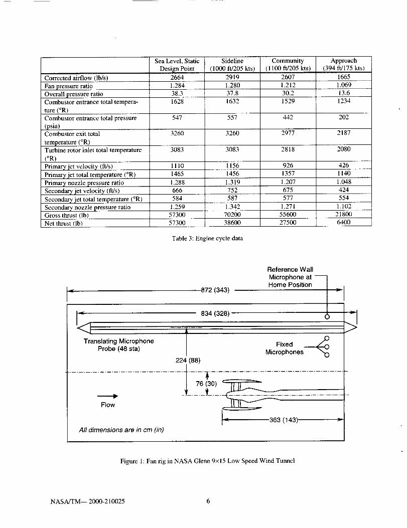
Correctedairflow(lb/s)FanpressureratioOverallpressureratioCombustorentrancetotaltempera-ture(°R)Combustorentrancetotalpressure(psia)Combustorexittotaltemperature(°R)Turbinerotorinlettotaltemperature(°R)Primaryjetvelocityfit/s)Primaryjettotaltemperature(°R)PrimarynozzlepressureratioSecondaryjetvelocityfit/s)Secondaryjet totaltemperature(°R)SecondarynozzlepressureratioGrossthrust(lb)
SeaLevel,StaticDesignPoint
26641.28438.31628
547
3260
3083
111014651.2886665841,259
Sidefine(lO00ft/205kts)
29191.28037.81632
557
3260
3O83
115614561.3197525871.342
Commumty(ll00fff205kts)
26071.21230.21529
442
2977
2818
92613571.2076755771.271
57300 70200 55600Netthrust(lb) 57300 38600 27500
Approach(394ft/175kts)
16651.06913.61234
202
2187
2080
42611401.0484245541.102218006400
Table3:Enginecycledata
872 (343)
Translating MicrophoneProbe (48 sta)
834 (328)
Reference Wall
Microphone at -_
Home Position
Fixed .__Microphones
Figure 1: Fan rig in NASA Glenn 9x 15 Low Speed Wind Tunnel
NASA/TM-- 2000-210025 6
145 [
140
135m
"_ 130
_J
m= 125
G_-o 120e,-
o
115
Narrow Band,
Mach 0.1
Scaled Tunnel Data
Narrow Band
Static, Smoothed,
Corrected Data
Broadband
Curve Fit 1BPF 2
1/3 Octave Band Sound
Pressure Levels
3 4
110
105
10 100 1000
Frequency (Hz)
Figure 2: Experimental fan noise data reduction
10000
ZQ.
>
¢)rr
Inlet .._i----" -" -"
Dischargem _
P&W Low Noise Fan 11I i l J I i i i I i 1 , I , I , I I I
0 20 40 60 80 100 120 140 160
Yaw Angle Re Inlet (deg)
Figure 3: Static fan noise comparison
180
NASA/TM-- 2000-210025 7
165
160
155
150
Static
Sideline Power J_
._.: _ 200 kts
z155
150
z 145
150
145
140
135
0 20 40 60 80 100 120 140 160 180
Yaw Angle Re Inlet (deg)
Figure 4: Experimental fan data, combined inlet and discharge fan noise, certification power settings
Figure 5: General arrangement of circa 2020 notional quad aircraft
NASA/TM-- 2000-210025 8
o}
rr
c-<t-
13..
180
160
140
120
100
8O
6O
40
20
0
10
Aft
BoSom
Fo re|
5dB
, , . . | • , • , , i
100 1000
1/3 Octave Band Center Frequency (Hz)
Figure 6: Inlet barrier attenuation
10000
180
160
140
_._ 120,&
--_ 100m
rr
(D8O
¢-<
" 60
0..
40
20
0
10
Aft
BoSom
Fo reI
5 dB
, , , , . * , i | * a | * i I
100 1000
1/3 Octave Band Center Frequency (Hz)
Figure 7: Discharge barrier attenuation
10000
NASA/TM-- 2000-210025 9
t_
.--I
D.
mO
T--
90
86
82
78
74
70
66
102
98
94
90
86
82
78
10
St°__ne_ SAE
L°Degrees
90i i l Illlll i i i lllall I I I I till
96
92
88
84
8O
76
72110 Degrees
i i I ,,1,,1 , . , , . , roll I I I I I
/SAE ,°2rSton
_ t Ston_'__
86
130Degrees \ %.................. \' "_- ..... 82
100 1000 10000 10 100 1000 10000
1/3 Octave Band Center Frequency (Hz)
Figure 8: Jet noise modeling
Fore
fAft Fore Aft
80 1 120 80
PNLT (PNdB) PNLT (PNdB)
120
Bottom
Four-Engine Fan Noise All Sources
Figure 9: Noise level variation in pitch angle: with and without wing barrier diffraction calculations
NASA/TM-- 2000-210025 10
m
ZQ.
Zn
100
95
9O
85
80
75
-10
Without Barrier Shielding
.T, t , • _ ,
-5 0 5 10
With Barrier Shielding ----e-- Total
Fan Inlet
Fan Discharge
Jet
-5 0 5 10
Obserwr -time Relative to Point of Closest Approach (s)
Figure 10: Community observer noise histories, with and without wing barrier diffraction calculations
95
9O
85
m
Zt2.
80._JZa_LU
75
70
65
[] Without Barrier Shielding
[] With Barrier Shielding
87.7 88.0
: : :: :: :: :: : :::: :: :
: : :::: : :: : : ::
::i : : ::::: :::: :::
:::::: :::
: : : ::: :: : ::: : :: : :::
i: i:
76.1 75.8: : : :i:
:: : ::_:::::
: :: : ::::
:: :.............. :: :::: :::::
........ ,:: ::::::,:
:i;i::::: :::: ........................: : :: ::::
:::: : :::::!i _i!iii!!!i_iii........ :::::: :: :
:: :: : :::
Fan Inlet Fan Total
Discharge
78.5 78.0
85.4
89.9
i
::: ::
::: ::
: :
::::: :
:: ::: :
: :: ::
::::: :
,:;:::
::::: :
Core Total
Engine
Fan Jet Airframe
Figure 11 : Sideline noise prediction, showing influence of wing bamer calculations
91.1
86.8
Total
NASA/TM-- 2000-210025 11
ZD.
--I
ZQ.iii
"0
ZELLLI
/
Z13.w
95
90
85
80
75
70
65
100
95
90
85
80
75
70
83.0 82.9
Fan Inlet
86.5 86.4
Fan Inlet
89.9
::::: ::::_::_:::
84.9
75.3
83.0
::. ................
×,.x::::::::::::::::::::::::::::::::::::::
:::::::::::::::::::::::::::::::::::::::::::::::::::::::
Fan Jet Core Total Airframe
Engine
Figure 12: Community noise prediction, showing influence of wing barrier calculations
47.0
82.0
91.9
Fan Total Fan Jet Core Total
Discharge Engine
92.9
Airframe
92.7
88.4
i
Total
95.6
Total
Figure 13: Approach noise prediction, showing influence of wing barrier calculations
NASA/TM_ 2000-210025 12

3OOO
2OOO
1000
0
-1000
-2000
-3000
90 EPNdB
x
3000
2O00
1000
0
-1000
-2000
-3000
-10000
95 EPNdB
I I I I I I
-5000 0 5000 10000 15000 20000 25000
Distance from Brake Release (if)
Figure 14: Plan view of runway with 90 and 95 EPNdB contours, showing influence of wing barrier calculations
NASA/TM-- 2000-210025 13
REPORT DOCUMENTATION PAGE FormApprovedOMB NO. 0704-0188
Publicreportingburdenfor thiscollectionofinformationis estimatedto average1 hourper response,includingthetimefor reviewinginstructions,searchingexistingdatasources,gatheringandmaintainingthedataneeded,andcompletingandreviewingthecollectionofinformation.Sendcommentsregardingthisburdenestimateor anyotheraspectofthiscollectionofinformation,includingsuggestionsfor reducingthisburden,to WashingtonHeadquartersServices,Directoratefor InformationOperationsandReports,1215JeffersonDavisHighway,Suite1204,Arlington,VA 22202-4302,andto theOfficeof ManagementandBudget,PaperworkReductionProject(0704-0188),Washington,DC 20503.
1. AGENCY USE ONLY (Leave blank) 2. REPORT DATE
April 2000
4. TITLE AND SUBTITLE
Noise Reduction Potential of Large, Over-the-Wing Mounted,
Advanced Turbofan Engines
6. AUTHOR(S)
Jeffrey J. Berton
7. PERFORMING ORGANIZATION NAME(S) AND ADDRESS(ES)
National Aeronautics and Space Administration
John H. Glenn Research Center at Lewis Field
Cleveland, Ohio 44135-3191
9. SPONSORING/MONITORING AGENCY NAME(S) AND ADDRESS(ES)
National Aeronautics and Space Administration
Washington, DC 20546-0001
,3. REPORT TYPE AND DATES COVERED
Technical Memorandum
5. FUNDING NUMBERS
WU - 714-99-20-(0
8. PERFORMING ORGANIZATIONREPORT NUMBER
E-12222
10. SPONSORING/MONITORINGAGENCY REPORT NUMBER
NASA TM--2000-210025
11. SUPPLEMENTARY NOTES
Prepared forthe 14thlnternationalSymposiumon Air Breathing Enginessponsored by thelnternationalSocietyforAir
Breathing Engines, Florence, ltaly, September5-10,1999. Responsible person, Jeffrey J. Berton, organization code 2400,.
(216) 977-7031.
12a. DISTRIBUTION/AVAILABILITY STATEMENT
Unclassified - Unlimited
Subject Category: 07 Distribution: Nonstandard
This publication is available from the NASA Center for AeroSpace Information, (301) 621 _)390.
12b. DISTRIBUTION CODE
13. ABSTRACT (Maximum 200 words)
As we look to the future, increasingly stringent civilian aviation noise regulations will require the design and manufac-
ture of extremely quiet commercial aircraft. Indeed, the noise goal for NASA's Aeronautics Enterprise calls for
technologies that will help to provide a 20 EPNdB reduction relative to today's levels by the year 2022. Further, the
large fan diameters of modern, increasingly higher bypass ratio engines pose a significant packaging and aircraft
installation challenge. One design approach that addresses both of these challenges is to mount the engines above the
wing. In addition to allowing the performance trend towards large, ultra high bypass ratio cycles to continue, this over-
the-wing design is believed to offer noise shielding benefits to observers on the ground. This paper describes the
analytical certification noise predictions of a notional, long haul, commercial quadjet transport with advanced, high
bypass engines mounted above the wing.
14. SUBJECT TERMS
Noise prediction (aircraft); Aircraft noise; Jet aircraft noise
17. SECURITY CLASSIFICATIONOF REPORT
Unclassified
NSN 7540-01-280-5500
18. SECURITY CLASSIFICATIONOF THIS PAGE
Unclassified
19. SECURITY CLASSIFICATIONOF ABSTRACT
Unclassified
15. NUMBER OF PAGES
1916. PRICE CODE
A03
20. LIMITATION OF ABSTRACT
Standard Form 298 (Rev. 2-89)Prescribed by ANSI Std. Z39-18
298-102