Embed Size (px)
Citation preview
AIAA Aviation 2015 Conference – 22-26 June 2015
1 American Institute of Aeronautics and Astronautics
Noise Measurements Of High Aspect Ratio Distributed Exhaust Systems
James Bridges* NASA Glenn Research Center, Cleveland, OH, 44135
This paper covers far-field acoustic measurements of a family of rectangular nozzles with aspect ratio 8, in the high subsonic flow regime. Several variations of nozzle geometry, commonly proposed for embedded exhaust systems, are explored, including bevels, slants, single broad chevrons and notches, and internal septae. Far-field acoustic results, presented previously for the simple rectangular nozzle, showed that increasing aspect ratio increases the high frequency noise, especially directed in the plane containing the minor axis of the nozzle. Detailed changes to the nozzle geometry generally made little difference in the noise, and the differences were greatest at low speed. Having an extended lip on one broad side (‘bevel’) did produce up to 3dB more noise in all directions, while extending the lip on the narrow side (‘slant’) produced up to 2dB more noise, primarily on the side with the extension. Adding a single, non-intrusive chevron, made no significant change to the noise, while inverting the chevron (‘notch’) produced up to 2dB increase in the noise. Having internal walls (‘septae’) within the nozzle, such as would be required for structural support or when multiple fan ducts are aggregated, reduced the noise of the rectangular jet, but could produce a highly directional shedding tone from the septae trailing edges. Finally, a nozzle with both septae and a beveled nozzle, representative of the exhaust system envisioned for a distributed propulsion aircraft with a common rectangular duct, produced almost as much noise as the beveled nozzle, with the septae not contributing much reduction in noise.
Nomenclature Dj = diameter, equivalent area h = short dimension of rectangular nozzle exit L = length of bevel, slant, chevron beyond exit of baseline nozzle Ma = acoustic Mach number, Uj/c∞ c∞ = speed of sound, ambient T∞ = temperature, ambient t = thickness of trailing edge of septum Uj = jet exit velocity, ideally expanded PSD = power spectral density of sound Stt = Strouhal number based on trailing edge of septum, frequency*t/Uj StD = Strouhal number based on equivalent jet diameter, frequency*Dj/Uj
I. Introduction NASA’s Advanced Air Vehicles Program is exploring aircraft designs that take entirely new approaches to the
problems of aero transport. Several of these conceptual aircraft require that the propulsion system be tightly integrated with the airframe, and often the nozzles have a high aspect ratio as well as other geometric features that make the nozzle very different from an axisymmetric nacelle. Currently there is a lack of adequate noise prediction methods that are known to successfully address the noise of high aspect ratio nozzles. In addition there is a desire to use aspects of the nozzle design to reduce the noise of the propulsive flow, such as shielding or enhanced mixing. As part of its exploration of nozzle concepts for quiet civilian supersonic aircraft, the NASA Commercial Supersonic Technology Project created a family of high aspect ratio nozzles, the Extensible Rectangular Nozzles (ERN). This
*Acoustics Branch, MS 54-3; AIAA Associate Fellow
https://ntrs.nasa.gov/search.jsp?R=20150022186 2018-05-16T09:49:37+00:00Z
AIAA Aviation 2015 Conference – 22-26 June 2015
2 American Institute of Aeronautics and Astronautics
paper presents acoustic results for an array of geometrical variants of rectangular nozzle such as is found in many proposed advanced aircraft.
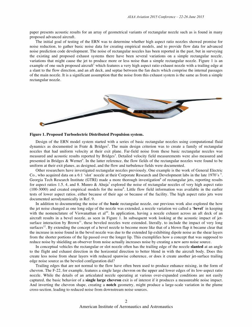
The initial goal of testing of the ERN was to determine whether high aspect ratio nozzles showed promise for noise reduction, to gather basic noise data for creating empirical models, and to provide flow data for advanced noise prediction code development. The noise of rectangular nozzles has been reported in the past, but in surveying the existing and proposed exhaust systems there have been several variations on a simple rectangular nozzle, variations that might cause the jet to produce more or less noise than a simple rectangular nozzle. Figure 1 is an example of one such proposed aircraft1 which features a very high aspect ratio exhaust nozzle with a trailing edge at a slant to the flow direction, and an aft deck, and septae between the fan ducts which comprise the internal passages of the main nozzle. It is a significant assumption that the noise from this exhaust system is the same as from a simple rectangular nozzle.
Figure 1. Proposed Turboelectric Distributed Propulsion system.
Design of the ERN model system started with a series of basic rectangular nozzles using computational fluid dynamics as documented in Frate & Bridges2. The main design criterion was to create a family of rectangular nozzles that had uniform velocity at their exit plane. Far-field noise from these basic rectangular nozzles was measured and acoustic results reported by Bridges3. Detailed velocity field measurements were also measured and presented in Bridges & Wernet4. In the latter reference, the flow fields of the rectangular nozzles were found to be uniform at their exit planes, as designed, and the flow and turbulence fields were documented.
Other researchers have investigated rectangular nozzles previously. One example is the work of General Electric Co., who acquired data on a 6:1 ‘slot’ nozzle at their Corporate Research and Development labs in the late 1970’s 5. Georgia Tech Research Institute (GTRI) made a more thorough investigation6 of rectangular jets, reporting results for aspect ratios 1.5, 4, and 8. Munro & Ahuja7 explored the noise of rectangular nozzles of very high aspect ratio (100-3000) and created empirical models for the noise8. Little flow field information was available in the earlier tests of lower aspect ratios, either because of their age or because of the facility. The high aspect ratio jets were documented aerodynamically in Ref. 9.
In addition to documenting the noise of the basic rectangular nozzle, our previous work also explored the how the jet noise changed as one long edge of the nozzle was extended, a nozzle variation we called a ‘bevel’ in keeping with the nomenclature of Viswanathan et al10. In application, having a nozzle exhaust across an aft deck of an aircraft results in a bevel nozzle, as seen in Figure 1. In subsequent work looking at the acoustic impact of jet-surface interaction by Brown11, these beveled nozzles were extended, literally, to include the impact of very long surfaces12. By extending the concept of a bevel nozzle to become more like that of a blown flap it became clear that the increase in noise found in the bevel nozzle was due to the extended lip exhibiting dipole noise as the shear layers from the shorter portions of the lip passed over the longer lip. This exemplifies how a concept that was supposed to reduce noise by shielding an observer from noise actually increases noise by creating a new aero noise source.
In conceptual vehicles the rectangular or slot nozzle often has the trailing edge of the nozzle slanted at an angle to the flight and exhaust direction in the horizontal direction to better blend in with the aircraft body. Does this create less noise from shear layers with reduced spanwise coherence, or does it create another jet-surface trailing edge noise source as the beveled configuration did?
Trailing edges that are not normal to the flow have often been used to produce enhance mixing, in the form of chevron. The F-22, for example, features a single large chevron on the upper and lower edges of its low-aspect ratio nozzle. While the details of an articulated nozzle operating at various over-expanded conditions are not easily captured, the basic behavior of a single large chevron exit is of interest if it produces a measureable noise impact. And inverting the chevron shape, creating a notch geometry, might produce a large-scale variation in the plume cross-section, leading to reduced noise from downstream noise sources.
AIAA Aviation 2015 Conference – 22-26 June 2015
3 American Institute of Aeronautics and Astronautics
Finally, practical considerations of non-circular pressure vessels require that rectangular nozzles either have significantly stronger shells, or internal bracing to maintain the shape of the nozzle. Or, as in the case of the Turboelectric Distributed Propulsion concept (Figure 1) the high-aspect-ratio nozzle is the accumulation of many fan ducts, each separated from its neighbor by a septum. These series of septae, or a series of internal bracing, could have significant acoustic impact on the exhaust system, impacts that need to be understood at least at a system study level, to allow proper assessment of a vehicle’s viability.
The nozzle designs examined in this paper are intended to provide one degree of realism beyond that of a simple rectangular nozzle, itself a level of detail beyond the one-dimensional (axisymmetric) noise models often used in aircraft system design. The extent to which these variations on a rectangular design have an acoustic impact is intended to only give a slightly more refined answer in a system level study.
Facility, Model Hardware, Flow Conditions, and Instrumentation
A. Facility The nozzle tests were conducted on the Small Hot Jet Acoustic Rig (SHJAR, pronounced with a silent ‘J’)
located in the Aeroacoustic Propulsion Laboratory (AAPL) at the NASA Glenn Research Center in Cleveland, Ohio. The SHJAR was developed to test jet noise reduction concepts at a low technology readiness level (TRL 1-3) and at minimum expense, and to conduct fundamental studies of jet noise and jet turbulent flow fields. The rig is described and baseline acoustic results for single-stream round jets are given in Ref. 13.
B. Model Hardware The model hardware being considered in this paper is all based on an 8:1 rectangular nozzle that has been
documented in a previous conference paper2. The 8:1 nozzle had height h = 0.668 inch (16.9mm) and width w = 5.336 inch (135.5mm) giving an equivalent diameter of 2.13 inches (54.1mm). The flow field was measured extensively with PIV and these results were reported in Ref. 4.
Beyond the basic rectangular nozzle, several variants were considered that embodied aspects of embedded exhaust systems found in existing and proposed aircraft. Table 1 gives the dimensions and visual sketch of each of the nozzles tested and reported. Adding an additional piece to the base rectangular nozzle created most of these variants, although the bevel was created as an integral nozzle. In earlier work [3] two extension lengths L/h were explored for rectangular nozzles of aspect ratios of 2, 4, and 8. In the present paper only the 8:1 nozzle is presented for comparison to other geometric variants on the rectangular nozzle.
Adding metal parts to the outer mold line of the basic rectangular nozzle created the slant, chevron, and notch nozzles. The surfaces of the added parts were carefully machined where they met the nozzle to produce a smooth surface continuing the inner surface of the nozzle. In all cases the additional parts maintained the same dimensions as the exit perimeter, so for instance the chevrons had zero penetration into the shear layer.
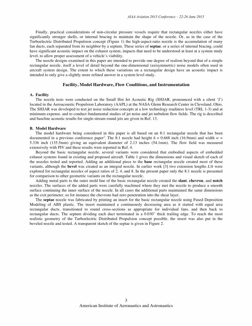
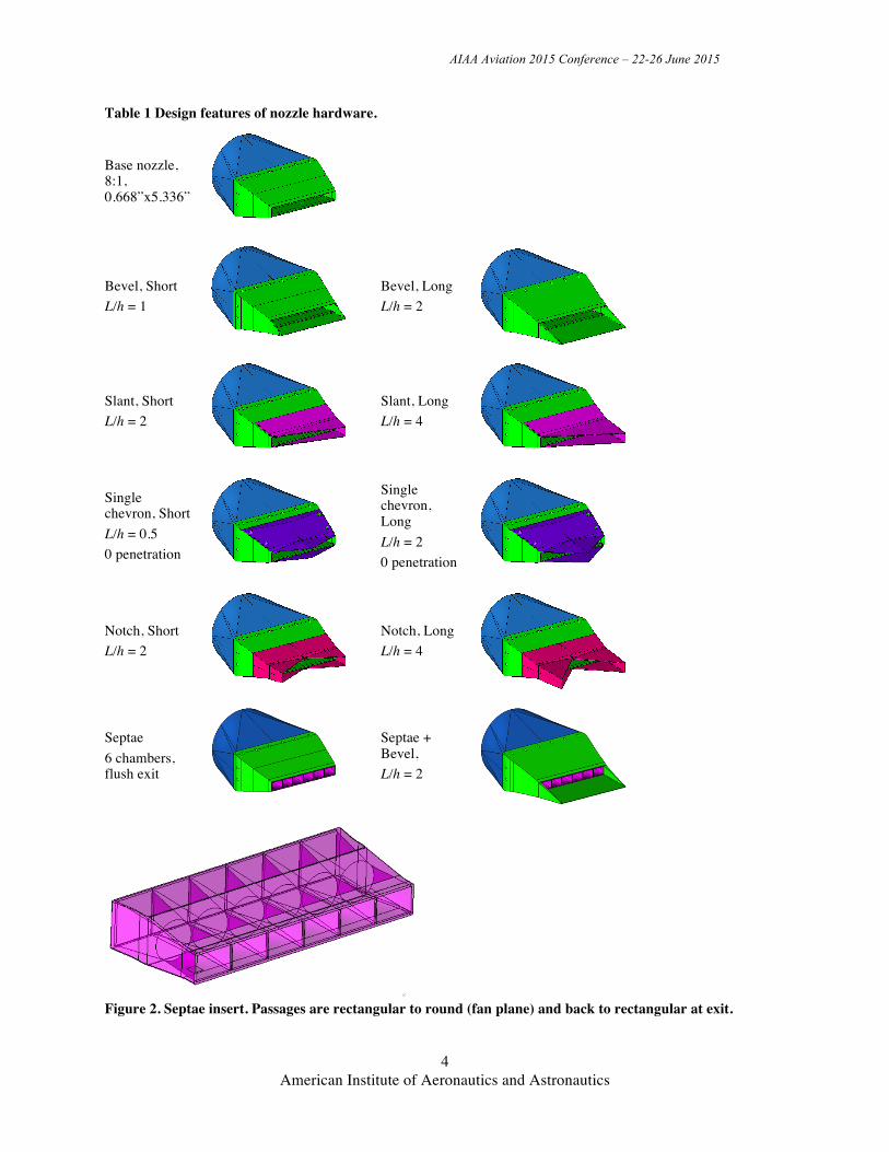
The septae nozzle was fabricated by printing an insert for the basic rectangular nozzle using Fused Deposition Modeling of ABS plastic. The insert maintained a continuously decreasing area as it started with equal area rectangular ducts, transitioned to round cross-sections as appropriate for individual fans, and then back to rectangular ducts. The septum dividing each duct terminated in a 0.030” thick trailing edge. To reach the most realistic geometry of the Turboelectric Distributed Propulsion concept possible, the insert was also put in the beveled nozzle and tested. A transparent sketch of the septae is given in Figure 2.
AIAA Aviation 2015 Conference – 22-26 June 2015
4 American Institute of Aeronautics and Astronautics
Table 1 Design features of nozzle hardware.
Base nozzle, 8:1, 0.668”x5.336”
Bevel, Short L/h = 1
Bevel, Long L/h = 2
Slant, Short L/h = 2
Slant, Long L/h = 4
Single chevron, Short L/h = 0.5 0 penetration
Single chevron, Long L/h = 2 0 penetration
Notch, Short L/h = 2
Notch, Long L/h = 4
Septae 6 chambers, flush exit
Septae + Bevel, L/h = 2
Figure 2. Septae insert. Passages are rectangular to round (fan plane) and back to rectangular at exit.
AIAA Aviation 2015 Conference – 22-26 June 2015
5 American Institute of Aeronautics and Astronautics
C. Flow conditions Because the test program had such a large number of geometries and a large number of orientations for each of
these geometries, only a cursory number of unheated subsonic flows were measured, 0.5 < Uj/c∞ < 0.9. For most of the paper only the highest speed will be shown and only when results varied significantly with acoustic Mach number will other conditions be discussed.
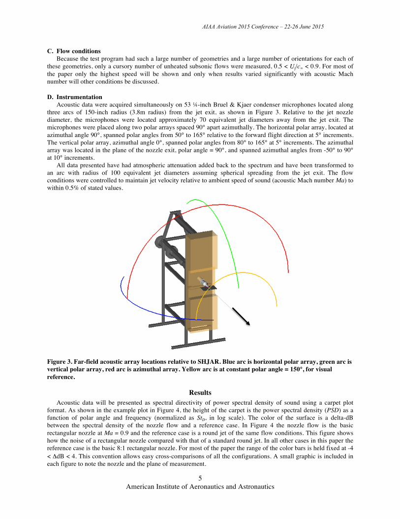
D. Instrumentation Acoustic data were acquired simultaneously on 53 ¼-inch Bruel & Kjaer condenser microphones located along
three arcs of 150-inch radius (3.8m radius) from the jet exit, as shown in Figure 3. Relative to the jet nozzle diameter, the microphones were located approximately 70 equivalent jet diameters away from the jet exit. The microphones were placed along two polar arrays spaced 90° apart azimuthally. The horizontal polar array, located at azimuthal angle 90°, spanned polar angles from 50° to 165° relative to the forward flight direction at 5° increments. The vertical polar array, azimuthal angle 0°, spanned polar angles from 80° to 165° at 5° increments. The azimuthal array was located in the plane of the nozzle exit, polar angle = 90°, and spanned azimuthal angles from -50° to 90° at 10° increments.
All data presented have had atmospheric attenuation added back to the spectrum and have been transformed to an arc with radius of 100 equivalent jet diameters assuming spherical spreading from the jet exit. The flow conditions were controlled to maintain jet velocity relative to ambient speed of sound (acoustic Mach number Ma) to within 0.5% of stated values.
Figure 3. Far-field acoustic array locations relative to SHJAR. Blue arc is horizontal polar array, green arc is vertical polar array, red arc is azimuthal array. Yellow arc is at constant polar angle = 150°, for visual reference.
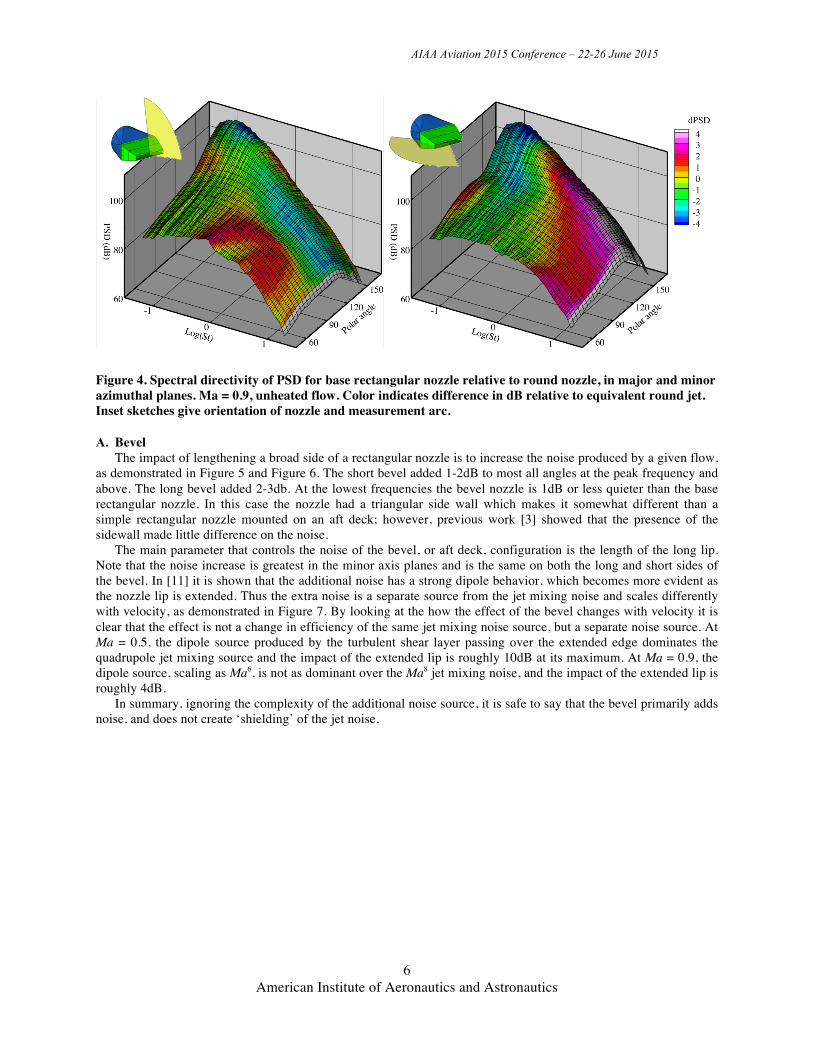
Results Acoustic data will be presented as spectral directivity of power spectral density of sound using a carpet plot
format. As shown in the example plot in Figure 4, the height of the carpet is the power spectral density (PSD) as a function of polar angle and frequency (normalized as StD, in log scale). The color of the surface is a delta-dB between the spectral density of the nozzle flow and a reference case. In Figure 4 the nozzle flow is the basic rectangular nozzle at Ma = 0.9 and the reference case is a round jet of the same flow conditions. This figure shows how the noise of a rectangular nozzle compared with that of a standard round jet. In all other cases in this paper the reference case is the basic 8:1 rectangular nozzle. For most of the paper the range of the color bars is held fixed at -4 < ΔdB < 4. This convention allows easy cross-comparisons of all the configurations. A small graphic is included in each figure to note the nozzle and the plane of measurement.
AIAA Aviation 2015 Conference – 22-26 June 2015
6 American Institute of Aeronautics and Astronautics
Figure 4. Spectral directivity of PSD for base rectangular nozzle relative to round nozzle, in major and minor azimuthal planes. Ma = 0.9, unheated flow. Color indicates difference in dB relative to equivalent round jet. Inset sketches give orientation of nozzle and measurement arc.
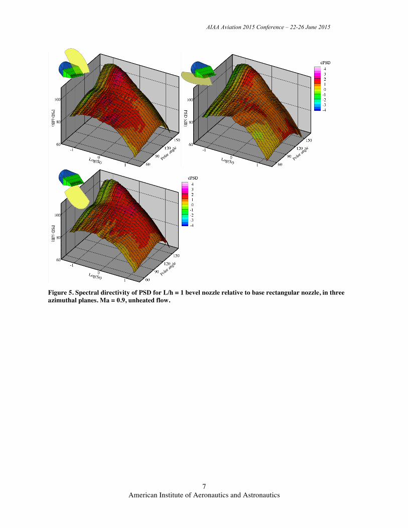
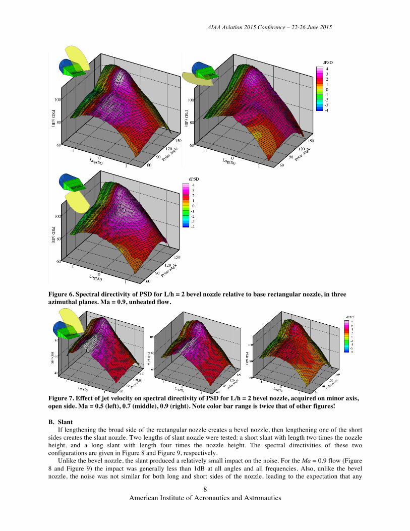
A. Bevel The impact of lengthening a broad side of a rectangular nozzle is to increase the noise produced by a given flow,
as demonstrated in Figure 5 and Figure 6. The short bevel added 1-2dB to most all angles at the peak frequency and above. The long bevel added 2-3db. At the lowest frequencies the bevel nozzle is 1dB or less quieter than the base rectangular nozzle. In this case the nozzle had a triangular side wall which makes it somewhat different than a simple rectangular nozzle mounted on an aft deck; however, previous work [3] showed that the presence of the sidewall made little difference on the noise.
The main parameter that controls the noise of the bevel, or aft deck, configuration is the length of the long lip. Note that the noise increase is greatest in the minor axis planes and is the same on both the long and short sides of the bevel. In [11] it is shown that the additional noise has a strong dipole behavior, which becomes more evident as the nozzle lip is extended. Thus the extra noise is a separate source from the jet mixing noise and scales differently with velocity, as demonstrated in Figure 7. By looking at the how the effect of the bevel changes with velocity it is clear that the effect is not a change in efficiency of the same jet mixing noise source, but a separate noise source. At Ma = 0.5, the dipole source produced by the turbulent shear layer passing over the extended edge dominates the quadrupole jet mixing source and the impact of the extended lip is roughly 10dB at its maximum. At Ma = 0.9, the dipole source, scaling as Ma6, is not as dominant over the Ma8 jet mixing noise, and the impact of the extended lip is roughly 4dB.
In summary, ignoring the complexity of the additional noise source, it is safe to say that the bevel primarily adds noise, and does not create ‘shielding’ of the jet noise.
AIAA Aviation 2015 Conference – 22-26 June 2015
7 American Institute of Aeronautics and Astronautics
Figure 5. Spectral directivity of PSD for L/h = 1 bevel nozzle relative to base rectangular nozzle, in three azimuthal planes. Ma = 0.9, unheated flow.
AIAA Aviation 2015 Conference – 22-26 June 2015
8 American Institute of Aeronautics and Astronautics
Figure 6. Spectral directivity of PSD for L/h = 2 bevel nozzle relative to base rectangular nozzle, in three azimuthal planes. Ma = 0.9, unheated flow.
Figure 7. Effect of jet velocity on spectral directivity of PSD for L/h = 2 bevel nozzle, acquired on minor axis, open side. Ma = 0.5 (left), 0.7 (middle), 0.9 (right). Note color bar range is twice that of other figures!
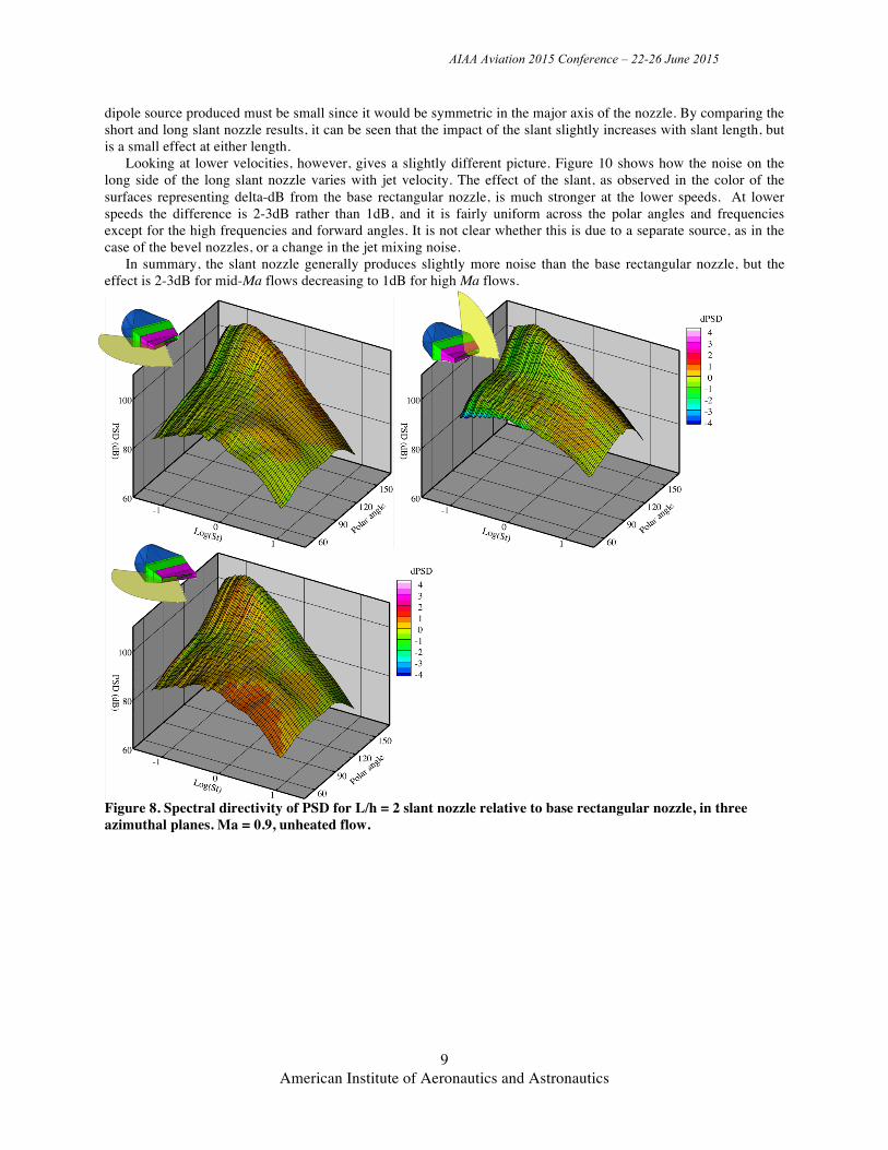
B. Slant If lengthening the broad side of the rectangular nozzle creates a bevel nozzle, then lengthening one of the short
sides creates the slant nozzle. Two lengths of slant nozzle were tested: a short slant with length two times the nozzle height, and a long slant with length four times the nozzle height. The spectral directivities of these two configurations are given in Figure 8 and Figure 9, respectively.
Unlike the bevel nozzle, the slant produced a relatively small impact on the noise. For the Ma = 0.9 flow (Figure 8 and Figure 9) the impact was generally less than 1dB at all angles and all frequencies. Also, unlike the bevel nozzle, the noise was not similar for both long and short sides of the nozzle, leading to the expectation that any
AIAA Aviation 2015 Conference – 22-26 June 2015
9 American Institute of Aeronautics and Astronautics
dipole source produced must be small since it would be symmetric in the major axis of the nozzle. By comparing the short and long slant nozzle results, it can be seen that the impact of the slant slightly increases with slant length, but is a small effect at either length.
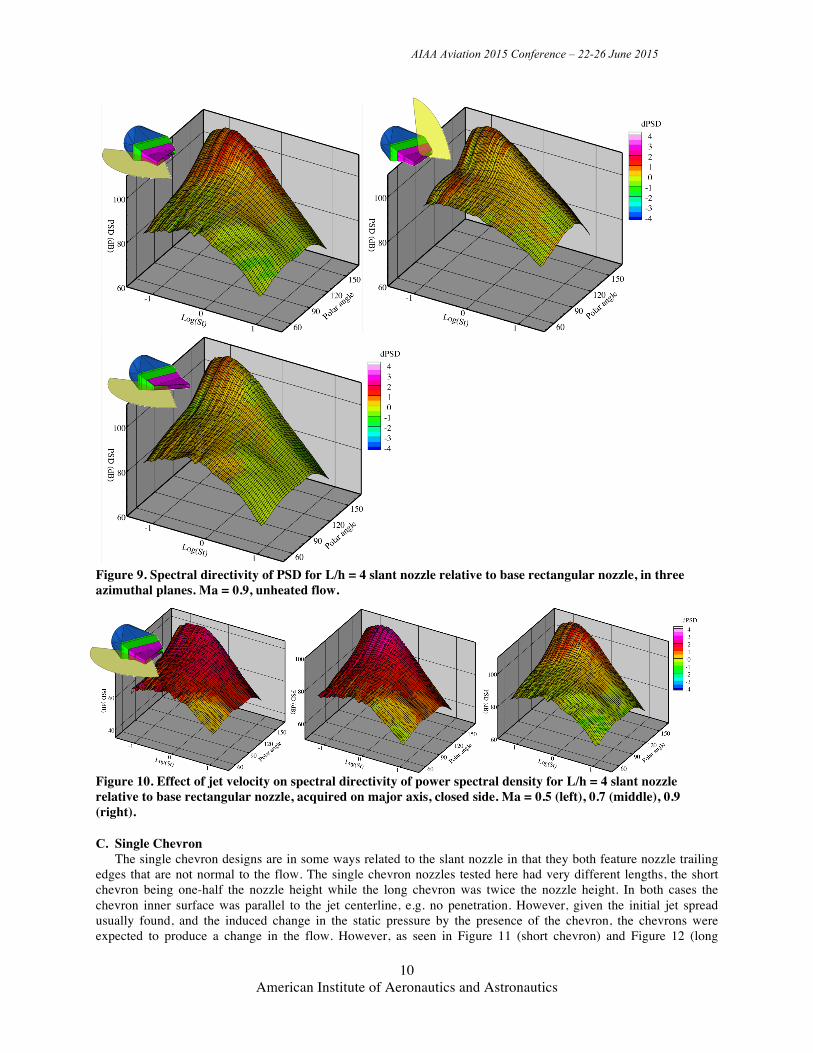
Looking at lower velocities, however, gives a slightly different picture. Figure 10 shows how the noise on the long side of the long slant nozzle varies with jet velocity. The effect of the slant, as observed in the color of the surfaces representing delta-dB from the base rectangular nozzle, is much stronger at the lower speeds. At lower speeds the difference is 2-3dB rather than 1dB, and it is fairly uniform across the polar angles and frequencies except for the high frequencies and forward angles. It is not clear whether this is due to a separate source, as in the case of the bevel nozzles, or a change in the jet mixing noise.
In summary, the slant nozzle generally produces slightly more noise than the base rectangular nozzle, but the effect is 2-3dB for mid-Ma flows decreasing to 1dB for high Ma flows.
Figure 8. Spectral directivity of PSD for L/h = 2 slant nozzle relative to base rectangular nozzle, in three azimuthal planes. Ma = 0.9, unheated flow.
AIAA Aviation 2015 Conference – 22-26 June 2015
10 American Institute of Aeronautics and Astronautics
Figure 9. Spectral directivity of PSD for L/h = 4 slant nozzle relative to base rectangular nozzle, in three azimuthal planes. Ma = 0.9, unheated flow.
Figure 10. Effect of jet velocity on spectral directivity of power spectral density for L/h = 4 slant nozzle relative to base rectangular nozzle, acquired on major axis, closed side. Ma = 0.5 (left), 0.7 (middle), 0.9 (right).
C. Single Chevron The single chevron designs are in some ways related to the slant nozzle in that they both feature nozzle trailing
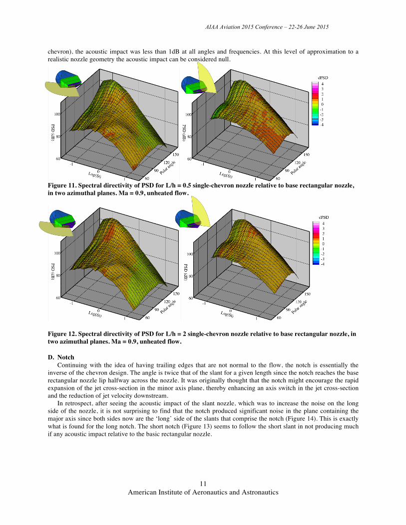
edges that are not normal to the flow. The single chevron nozzles tested here had very different lengths, the short chevron being one-half the nozzle height while the long chevron was twice the nozzle height. In both cases the chevron inner surface was parallel to the jet centerline, e.g. no penetration. However, given the initial jet spread usually found, and the induced change in the static pressure by the presence of the chevron, the chevrons were expected to produce a change in the flow. However, as seen in Figure 11 (short chevron) and Figure 12 (long
AIAA Aviation 2015 Conference – 22-26 June 2015
11 American Institute of Aeronautics and Astronautics
chevron), the acoustic impact was less than 1dB at all angles and frequencies. At this level of approximation to a realistic nozzle geometry the acoustic impact can be considered null.
Figure 11. Spectral directivity of PSD for L/h = 0.5 single-chevron nozzle relative to base rectangular nozzle, in two azimuthal planes. Ma = 0.9, unheated flow.
Figure 12. Spectral directivity of PSD for L/h = 2 single-chevron nozzle relative to base rectangular nozzle, in two azimuthal planes. Ma = 0.9, unheated flow.
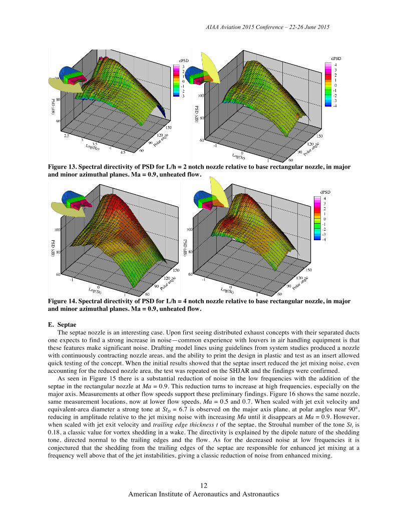
D. Notch Continuing with the idea of having trailing edges that are not normal to the flow, the notch is essentially the
inverse of the chevron design. The angle is twice that of the slant for a given length since the notch reaches the base rectangular nozzle lip halfway across the nozzle. It was originally thought that the notch might encourage the rapid expansion of the jet cross-section in the minor axis plane, thereby enhancing an axis switch in the jet cross-section and the reduction of jet velocity downstream.
In retrospect, after seeing the acoustic impact of the slant nozzle, which was to increase the noise on the long side of the nozzle, it is not surprising to find that the notch produced significant noise in the plane containing the major axis since both sides now are the ‘long’ side of the slants that comprise the notch (Figure 14). This is exactly what is found for the long notch. The short notch (Figure 13) seems to follow the short slant in not producing much if any acoustic impact relative to the basic rectangular nozzle.
AIAA Aviation 2015 Conference – 22-26 June 2015
12 American Institute of Aeronautics and Astronautics
Figure 13. Spectral directivity of PSD for L/h = 2 notch nozzle relative to base rectangular nozzle, in major and minor azimuthal planes. Ma = 0.9, unheated flow.
Figure 14. Spectral directivity of PSD for L/h = 4 notch nozzle relative to base rectangular nozzle, in major and minor azimuthal planes. Ma = 0.9, unheated flow.
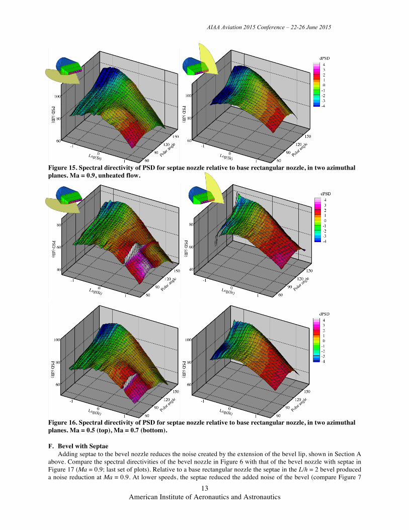
E. Septae The septae nozzle is an interesting case. Upon first seeing distributed exhaust concepts with their separated ducts
one expects to find a strong increase in noise—common experience with louvers in air handling equipment is that these features make significant noise. Drafting model lines using guidelines from system studies produced a nozzle with continuously contracting nozzle areas, and the ability to print the design in plastic and test as an insert allowed quick testing of the concept. When the initial results showed that the septae insert reduced the jet mixing noise, even accounting for the reduced nozzle area, the test was repeated on the SHJAR and the findings were confirmed.
As seen in Figure 15 there is a substantial reduction of noise in the low frequencies with the addition of the septae in the rectangular nozzle at Ma = 0.9. This reduction turns to increase at high frequencies, especially on the major axis. Measurements at other flow speeds support these preliminary findings. Figure 16 shows the same nozzle, same measurement locations, now at lower flow speeds, Ma = 0.5 and 0.7. When scaled with jet exit velocity and equivalent-area diameter a strong tone at StD = 6.7 is observed on the major axis plane, at polar angles near 90°, reducing in amplitude relative to the jet mixing noise with increasing Ma until it disappears at Ma = 0.9. However, when scaled with jet exit velocity and trailing edge thickness t of the septae, the Strouhal number of the tone Stt is 0.18, a classic value for vortex shedding in a wake. The directivity is explained by the dipole nature of the shedding tone, directed normal to the trailing edges and the flow. As for the decreased noise at low frequencies it is conjectured that the shedding from the trailing edges of the septae are responsible for enhanced jet mixing at a frequency well above that of the jet instabilities, giving a classic reduction of noise from enhanced mixing.
AIAA Aviation 2015 Conference – 22-26 June 2015
13 American Institute of Aeronautics and Astronautics
Figure 15. Spectral directivity of PSD for septae nozzle relative to base rectangular nozzle, in two azimuthal planes. Ma = 0.9, unheated flow.
Figure 16. Spectral directivity of PSD for septae nozzle relative to base rectangular nozzle, in two azimuthal planes. Ma = 0.5 (top), Ma = 0.7 (bottom).
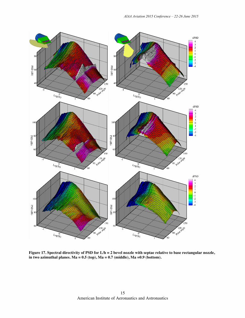
F. Bevel with Septae Adding septae to the bevel nozzle reduces the noise created by the extension of the bevel lip, shown in Section A
above. Compare the spectral directivities of the bevel nozzle in Figure 6 with that of the bevel nozzle with septae in Figure 17 (Ma = 0.9; last set of plots). Relative to a base rectangular nozzle the septae in the L/h = 2 bevel produced a noise reduction at Ma = 0.9. At lower speeds, the septae reduced the added noise of the bevel (compare Figure 7
AIAA Aviation 2015 Conference – 22-26 June 2015
14 American Institute of Aeronautics and Astronautics
with Figure 17); however, the septae+bevel combination was still louder than the base rectangular nozzle at all frequencies above the peak at all polar angles, as shown in Figure 17. (When comparing figures, note that Figure 7 uses a color bar with twice the range.) The presence of the bevel did not reduce the shedding tone from the septae in the major axis.
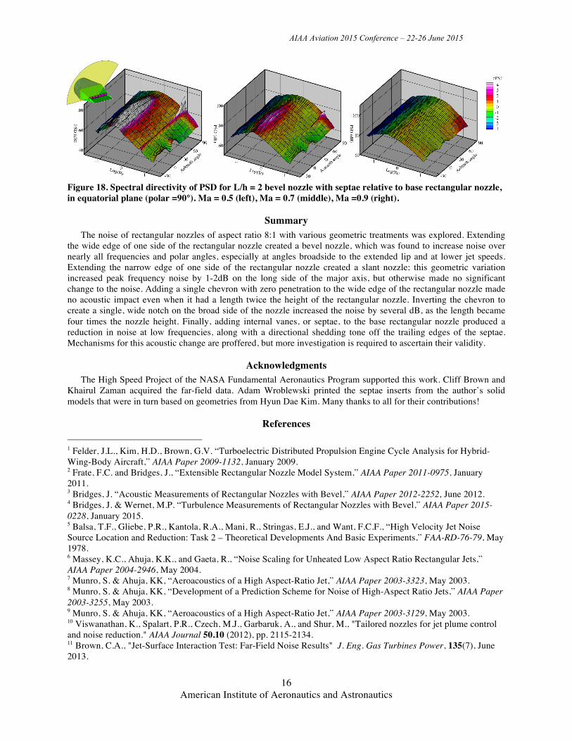
An interesting view of the effects of the septae+bevel combination is the spectral directivity in the azimuthal plane defined by polar angle 90° (Figure 18). In this view, at the lower speeds, the dipole arising from the extended lip of the bevel nozzle shows a distinctive maximum at azimuthal angle 0° (minor axis), while the tones from the septae peak strongly at azimuthal angle 90°. Both of these sources are subsumed by the jet mixing noise by Ma = 0.9. In high-speed flows, the increase in the high frequency region, which likely will scale into the range of human annoyance, is isolated to the major axis, and not directed strongly to the ground. At lower speeds, however, the bevel+septae combination nozzle will produce more noise on the ground than will the base rectangular nozzle.
AIAA Aviation 2015 Conference – 22-26 June 2015
15 American Institute of Aeronautics and Astronautics
Figure 17. Spectral directivity of PSD for L/h = 2 bevel nozzle with septae relative to base rectangular nozzle, in two azimuthal planes. Ma = 0.5 (top), Ma = 0.7 (middle), Ma =0.9 (bottom).
AIAA Aviation 2015 Conference – 22-26 June 2015
16 American Institute of Aeronautics and Astronautics
Figure 18. Spectral directivity of PSD for L/h = 2 bevel nozzle with septae relative to base rectangular nozzle, in equatorial plane (polar =90°). Ma = 0.5 (left), Ma = 0.7 (middle), Ma =0.9 (right).
Summary The noise of rectangular nozzles of aspect ratio 8:1 with various geometric treatments was explored. Extending
the wide edge of one side of the rectangular nozzle created a bevel nozzle, which was found to increase noise over nearly all frequencies and polar angles, especially at angles broadside to the extended lip and at lower jet speeds. Extending the narrow edge of one side of the rectangular nozzle created a slant nozzle; this geometric variation increased peak frequency noise by 1-2dB on the long side of the major axis, but otherwise made no significant change to the noise. Adding a single chevron with zero penetration to the wide edge of the rectangular nozzle made no acoustic impact even when it had a length twice the height of the rectangular nozzle. Inverting the chevron to create a single, wide notch on the broad side of the nozzle increased the noise by several dB, as the length became four times the nozzle height. Finally, adding internal vanes, or septae, to the base rectangular nozzle produced a reduction in noise at low frequencies, along with a directional shedding tone off the trailing edges of the septae. Mechanisms for this acoustic change are proffered, but more investigation is required to ascertain their validity.
Acknowledgments The High Speed Project of the NASA Fundamental Aeronautics Program supported this work. Cliff Brown and
Khairul Zaman acquired the far-field data. Adam Wroblewski printed the septae inserts from the author’s solid models that were in turn based on geometries from Hyun Dae Kim. Many thanks to all for their contributions!
References 1 Felder, J.L., Kim, H.D., Brown, G.V. “Turboelectric Distributed Propulsion Engine Cycle Analysis for Hybrid-Wing-Body Aircraft,” AIAA Paper 2009-1132, January 2009. 2 Frate, F.C. and Bridges, J., “Extensible Rectangular Nozzle Model System,” AIAA Paper 2011-0975, January 2011. 3 Bridges, J. “Acoustic Measurements of Rectangular Nozzles with Bevel,” AIAA Paper 2012-2252, June 2012. 4 Bridges, J. & Wernet, M.P. “Turbulence Measurements of Rectangular Nozzles with Bevel,” AIAA Paper 2015-0228, January 2015. 5 Balsa, T.F., Gliebe, P.R., Kantola, R.A., Mani, R., Stringas, E.J., and Want, F.C.F., “High Velocity Jet Noise Source Location and Reduction: Task 2 – Theoretical Developments And Basic Experiments,” FAA-RD-76-79, May 1978. 6 Massey, K.C., Ahuja, K.K., and Gaeta, R., “Noise Scaling for Unheated Low Aspect Ratio Rectangular Jets,” AIAA Paper 2004-2946, May 2004. 7 Munro, S. & Ahuja, KK, “Aeroacoustics of a High Aspect-Ratio Jet,” AIAA Paper 2003-3323, May 2003. 8 Munro, S. & Ahuja, KK, “Development of a Prediction Scheme for Noise of High-Aspect Ratio Jets,” AIAA Paper 2003-3255, May 2003. 9 Munro, S. & Ahuja, KK, “Aeroacoustics of a High Aspect-Ratio Jet,” AIAA Paper 2003-3129, May 2003. 10 Viswanathan, K., Spalart, P.R., Czech, M.J., Garbaruk, A., and Shur, M., "Tailored nozzles for jet plume control and noise reduction." AIAA Journal 50.10 (2012), pp. 2115-2134. 11 Brown, C.A., "Jet-Surface Interaction Test: Far-Field Noise Results" J. Eng. Gas Turbines Power, 135(7), June 2013.
AIAA Aviation 2015 Conference – 22-26 June 2015
17 American Institute of Aeronautics and Astronautics
12 Bridges, J., "Noise from aft deck exhaust nozzles–differences in experimental embodiments." AIAA Paper 2014-0876 (2014). 13 Brown, C.A. & Bridges, J., “Small Hot Jet Acoustic Rig Validation,” NASA TM—2006/214234, 2006.