Embed Size (px)
DESCRIPTION
Noise Budget Development for the LIGO 40 Meter Prototype. Ryan Kinney University of Missouri-Rolla, Department of Physics, 1870 Miner Circle, Rolla, MO 65409, USA. Introduction. LIGO 40 meter prototype Transfer Functions What is a Noise Budget? Seismic Noise Example. 40m Prototype. - PowerPoint PPT Presentation
Citation preview
Caltech, Aug. 19, 2005 Dr. Alan Weinstein
Noise Budget Development for the LIGO 40 Meter Prototype
Ryan Kinney
University of Missouri-Rolla, Department of Physics, 1870 Miner Circle, Rolla, MO 65409, USA
Caltech, Aug. 19, 2005 Dr. Alan Weinstein
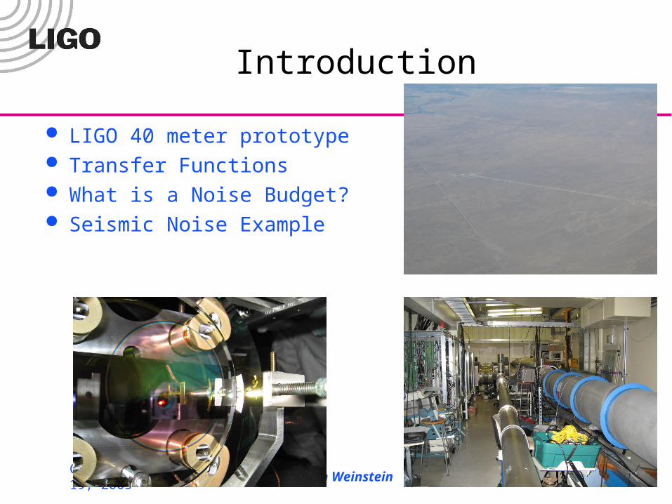
Introduction
LIGO 40 meter prototype Transfer Functions What is a Noise Budget? Seismic Noise Example
Caltech, Aug. 19, 2005 Dr. Alan Weinstein
40m Prototype
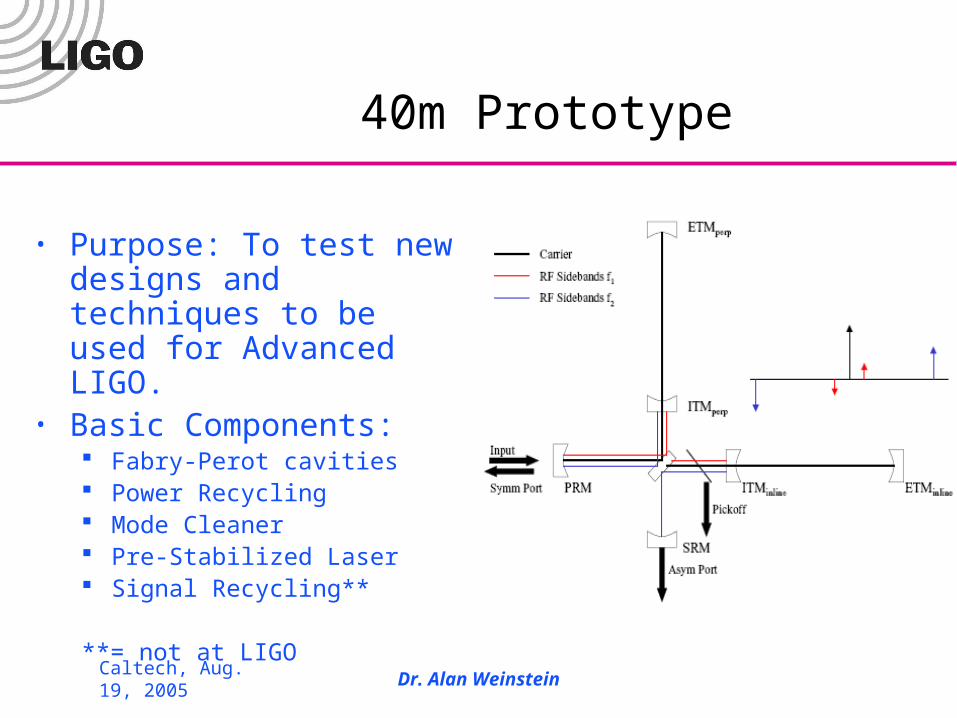
• Purpose: To test new designs and techniques to be used for Advanced LIGO.
• Basic Components: Fabry-Perot cavities Power Recycling Mode Cleaner Pre-Stabilized Laser Signal Recycling**
**= not at LIGO
Caltech, Aug. 19, 2005 Dr. Alan Weinstein
Transfer Functions for the Non-Believer
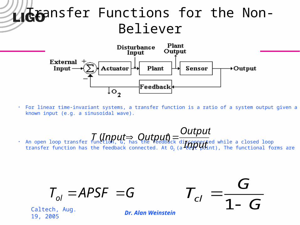
• For linear time-invariant systems, a transfer function is a ratio of a system output given a known input (e.g. a sinusoidal wave).
• An open loop transfer function, G, has the feedback disconnected while a closed loop transfer function has the feedback connected. At O2 (a test point), The functional forms are
Input
OutputOutputInputT )(
GAPSFTol G
GTcl
1
Caltech, Aug. 19, 2005 Dr. Alan Weinstein
Noise Sources
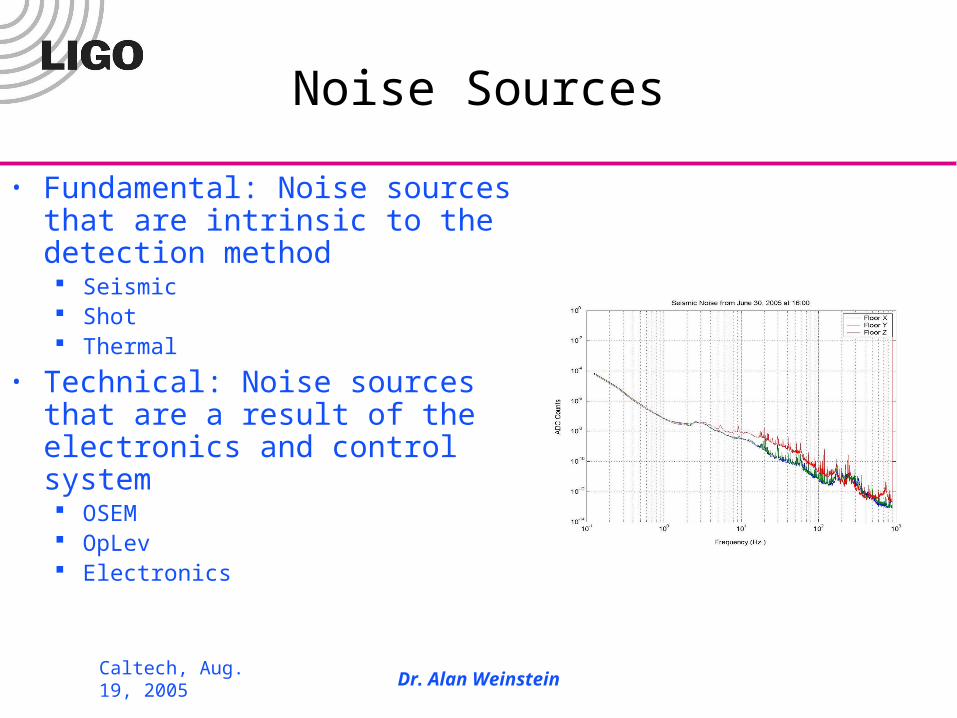
• Fundamental: Noise sources that are intrinsic to the detection method Seismic Shot Thermal
• Technical: Noise sources that are a result of the electronics and control system OSEM OpLev Electronics
Caltech, Aug. 19, 2005 Dr. Alan Weinstein
What is a Noise Budget?
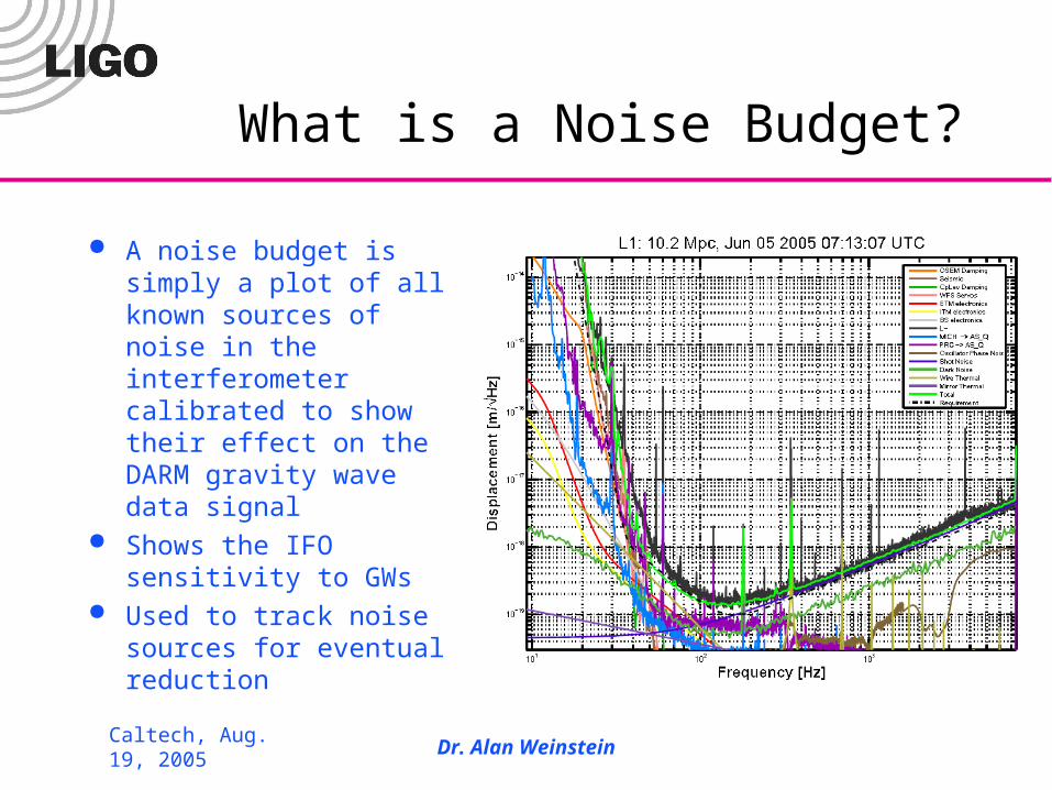
A noise budget is simply a plot of all known sources of noise in the interferometer calibrated to show their effect on the DARM gravity wave data signal
Shows the IFO sensitivity to GWs
Used to track noise sources for eventual reduction
Caltech, Aug. 19, 2005 Dr. Alan Weinstein
Process
Pick Noise source Measure noise spectrum (power spectrum) Calibrate to units of meters/rtHz (calibration
constants and transfer functions) Plot against DARM signal
Caltech, Aug. 19, 2005 Dr. Alan Weinstein
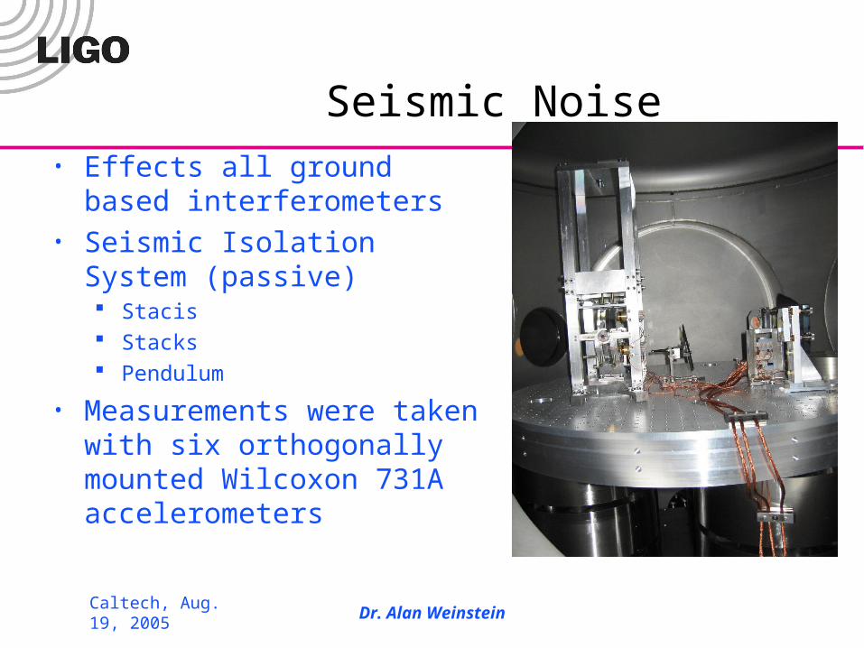
Seismic Noise• Effects all ground based
interferometers• Seismic Isolation System
(passive) Stacis Stacks Pendulum
• Measurements were taken with six orthogonally mounted Wilcoxon 731A accelerometers
Caltech, Aug. 19, 2005 Dr. Alan Weinstein
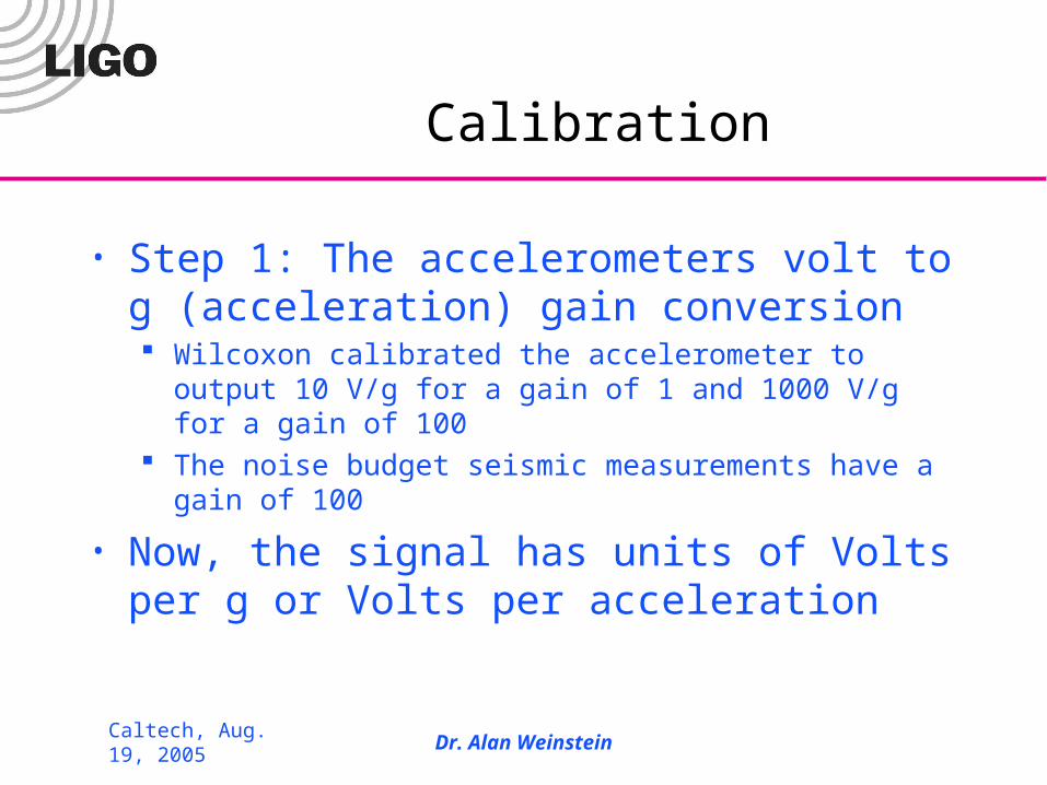
Calibration
• Step 1: The accelerometers volt to g (acceleration) gain conversion Wilcoxon calibrated the accelerometer to output 10 V/g for a
gain of 1 and 1000 V/g for a gain of 100 The noise budget seismic measurements have a gain of 100
• Now, the signal has units of Volts per g or Volts per acceleration
Caltech, Aug. 19, 2005 Dr. Alan Weinstein
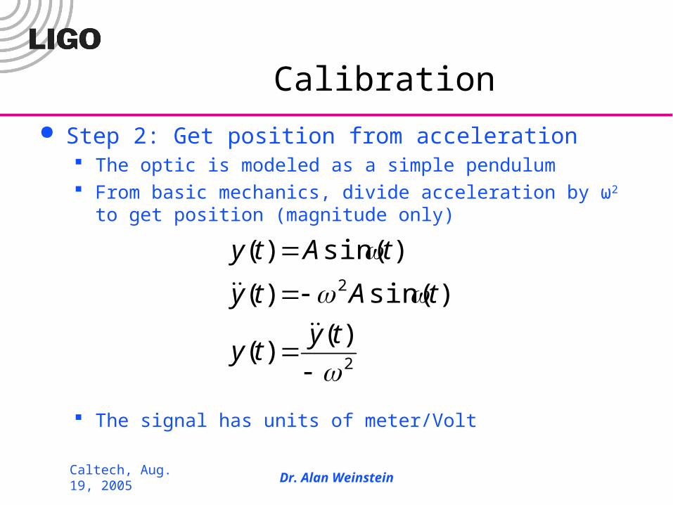
Calibration
Step 2: Get position from acceleration The optic is modeled as a simple pendulum From basic mechanics, divide acceleration by ω2 to get position
(magnitude only)
The signal has units of meter/Volt
2
2
)()(
)sin()(
)sin()(
tyty
tAty
tAty
Caltech, Aug. 19, 2005 Dr. Alan Weinstein
Calibration
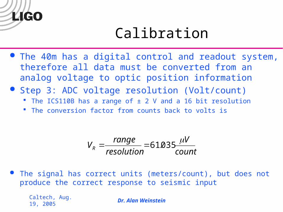
The 40m has a digital control and readout system, therefore all data must be converted from an analog voltage to optic position information
Step 3: ADC voltage resolution (Volt/count) The ICS110B has a range of ± 2 V and a 16 bit resolution The conversion factor from counts back to volts is
The signal has correct units (meters/count), but does not produce the correct response to seismic input
count
V
resolution
rangeVR
035.61
Caltech, Aug. 19, 2005 Dr. Alan Weinstein
Seismic Isolation Transfer Function
• Step 4: Multiply the calibrated signal by the seismic isolation transfer function to get the correct response of the optic to seismic motion
• This transfer function incorporates the stacks and the pendulum, but leaves out the stacis units passive contribution to noise damping
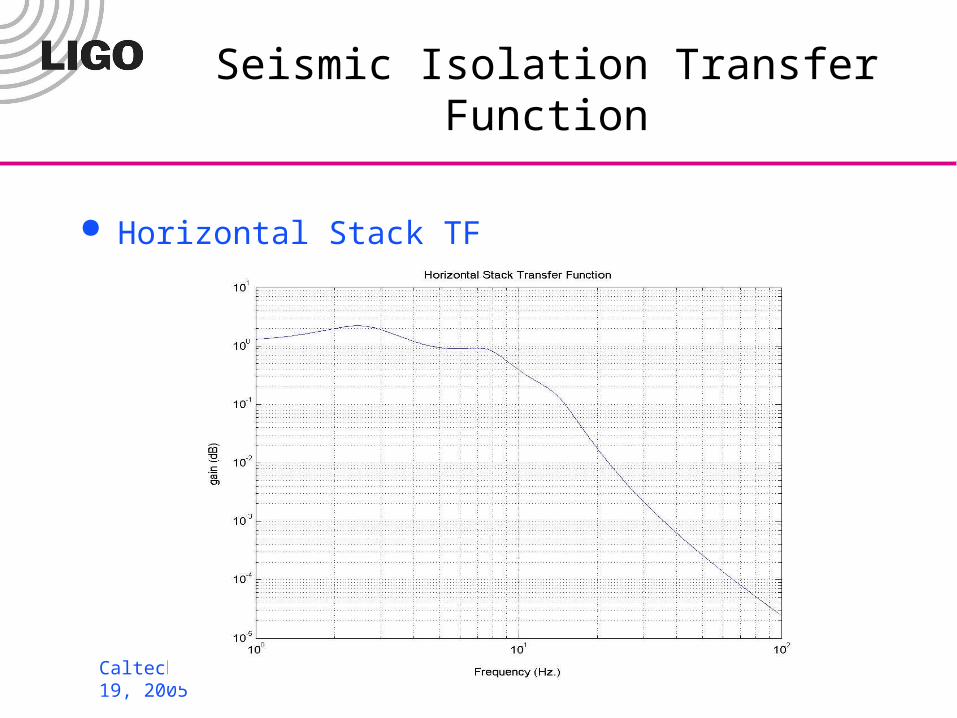
• Horizontal Stack transfer function Resonant at 3, 8.25, and 15 Hz
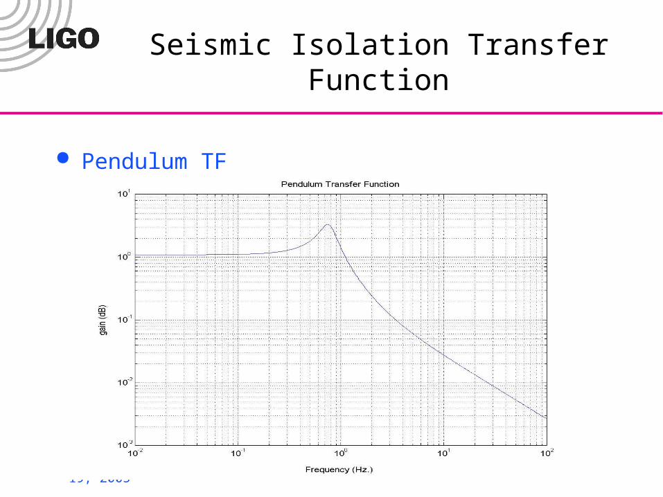
• Pendulum transfer function Resonant at 0.8 Hz.
Caltech, Aug. 19, 2005 Dr. Alan Weinstein
Seismic Isolation Transfer Function
Horizontal Stack TF
Caltech, Aug. 19, 2005 Dr. Alan Weinstein
Seismic Isolation Transfer Function
Pendulum TF
Caltech, Aug. 19, 2005 Dr. Alan Weinstein
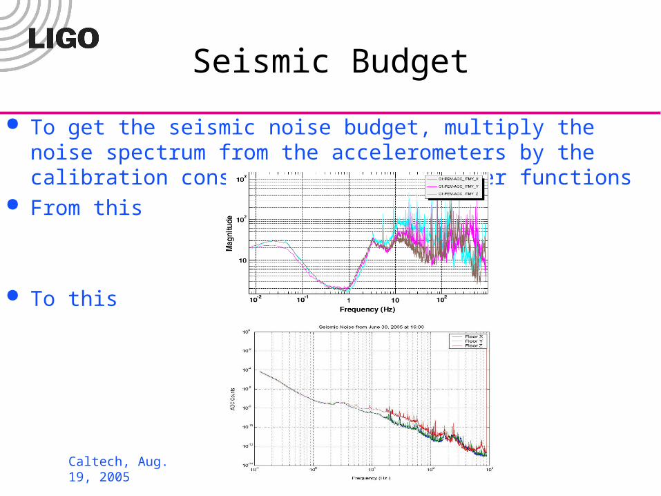
Seismic Budget
To get the seismic noise budget, multiply the noise spectrum from the accelerometers by the calibration constants and the transfer functions
From this
To this
Caltech, Aug. 19, 2005 Dr. Alan Weinstein
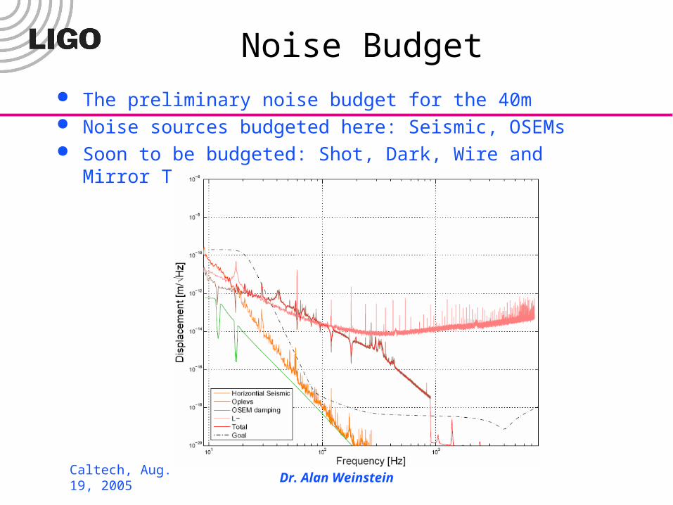
Noise Budget The preliminary noise budget for the 40m Noise sources budgeted here: Seismic, OSEMs Soon to be budgeted: Shot, Dark, Wire and Mirror Thermal,
OpLevs
Caltech, Aug. 19, 2005 Dr. Alan Weinstein
Future Work
Complete the noise budget by including more noise sources
Known noise sources: Wire Thermal, Mirror Thermal, Shot, Dark, Electronic, Intensity, Frequency, MICH, PRC, SRC
Unknown sources: Find and budget Use the budget to improve the 40m IFO performance
Caltech, Aug. 19, 2005 Dr. Alan Weinstein
Recognition
I would like to thank
Dr. Alan Weinstein Dr. Rana Adhikari Dr. David Blair Dr. Vuk Mandic Dr. Osamu Miyakawa Dr. Monica Varella
Ben Abbott Dan Busby Jay Heefner Steve Vass Rob Ward National Science Foundation California Institute of Technology