Embed Size (px)
Citation preview
No part of this document may be reproduced in anyform or by any means without the express writtenconsent of UPS Aviation Technologies, Inc.
II Morrow, UPS Aviation Technologies, and Apollo aretrademarks of UPS Aviation Technologies, Inc.© 2001 by UPS Aviation Technologies, Inc. All rightsreserved.Printed in the U.S.A.
UPS Aviation Technologies, Inc.Consumer Products Division2345 Turner Road, S.E.Salem, OR 97302
U.S.A. Toll Free 800.525.6726Canada Toll Free 800.654.3415International 503.391.3411FAX 503.364.2138
Visit our web page at http://www.upsat.comSend comments about this manual by email to:[email protected]
Welcome ...Welcome to a new era of aviation navigation. Once
again, II Morrow Inc. has set new standards in
features and ease of use for the general aviation
public. The Apollo GX-series of products are
unequaled in providing the features, level of
performance, and reliability that aviation users
require. The Apollo GX-series sets a precedent that
will be the standard to which all other avionics will be
compared.
The Apollo GX50 is a full-featured GPS receiver that
is IFR-certified for non-precision approach. The
GX55 GPS receiver is IFR-certified for en route
operation and designed to slide into your existing
Apollo Loran or Flybuddy GPS receiver mounting
tube. The GX60 combines the features of the GX50
with a revolutionary comm radio. The GX65 has the
comm features of the GX60, but is not IFR approach
certified and does not have the approach features.
You can be confident in knowing that you are the
owner of the state-of-the-art in aviation navigation
and communication. Our products are built to last
and to satisfy your navigation needs.
Read the Introduction and Getting Started sections of
the User’s Guide before you use your Apollo GX;
these sections will give you the “rules of the road.”
You can then refer to the other sections as a reference
for the power you have at your fingertips with the
most comprehensive navigation equipment available.
You will note that your User’s Guide may be missing
some sections. This guide serves the entire family of
Apollo GX products, but will only include the
sections that reflect the features available in the
product that you purchased. If you have an interest in
the features and operation of the other models, see the
section on Ordering Information.
i
History of RevisionsRevision Date Software Ver. Manual P/N
January 1998 2.1 560-0961-00June 1998 2.2 560-0961-01January 1999 2.2 560-0961-01aMarch 1999 3.0 560-0961-02July 2001 3.3 560-0961-03
Ordering InformationTo receive additional copies of the Apollo GX50/55/60/65manuals order the following part numbers:
User’s Guide 560-0961-xxApproach User’s Guide Insert 560-0928-xxGX60/65 Comm User’s Guide Insert 560-0963-xxUser’s Guide Binder (1") 560-9000User’s Guide Binder (3/4”) 560-9002User’s Guide Binder (1-1/2”) 560-9005GX50/60/65 Installation Manual 560-0959-xxGX50/60/65 SW Ver 3.3 Installation ManualUpgrade Supplement 561-0275-xxA-33 Antenna Installation Guide 560-0949-xxGX55 Installation Manual 560-0960-xxGX50 Quick Reference 561-0238-xxGX55 Quick Reference 561-0237-xxGX60/65 Quick Reference 561-0236-xxGX65 User’s Guide Insert 561-0256-xx
ii
Important Notice
iii
The Global Positioning System (GPS) is operated by the United States Department of Defense which is solelyresponsible for the accuracy, daily operation, and maintenance of the satellite constellation. System accuracy isaffected by the Department of Defense’s Selective Availability (SA) and the Dilution of Precision (DOP) attributed topoor satellite geometry.
Due to implementation of Selective Availability by the United States Department of Defense (DoD), all GPS receiversmay suffer degradation of position accuracy. The DoD has stated that 95% of the time horizontal accuracy will not bedegraded more than 100 m and 99.9% of the time accuracy will not be degraded more than 300 m.
Installations of TSO C-129a authorized Apollo GX50/60’s and TSO-C-129 authorized GX55’s may be approved forsupplemental navigation only. The Apollo GX50, GX55, or GX60 may be used as the primary navigation datadisplay, however, other means of navigation appropriate to the intended route of flight must be installed andoperational. It is not required that these other systems be monitored.
FCC Notice
This equipment has been tested and found to comply with the limits for a Class B digital device, pursuant to part 15 ofthe FCC Rules. These limits are designed to provide reasonable protection against harmful interference duringresidential use. Operation is subject to the following two conditions: (1) this device may not cause harmfulinterference, and (2) this device must accept any interference received, including interference that may causeundesired operation. This equipment generates, uses and can radiate radio frequency energy and, if not installed andused in accordance with the instructions, may cause harmful interference to radio communications. However, there isno guarantee that interference will not occur in a particular installation. If this equipment does cause harmfulinterference to radio or television reception, which can be determined by turning the equipment off and on, the user isencouraged to try to correct the interference by one or more of the following measures:
• Reorient or relocate the receiving antenna.
• Increase the separation between the equipment and receiver.
• Connect the equipment into an outlet on a circuit different from the one the receiver is connected.
• Consult the dealer or an experienced radio/TV technician for help.
Changes or modifications to this equipment not expressly approved by II Morrow Inc. could void the user’s authority tooperate this equipment.
Canadian Notice
This Class B digital apparatus meets all requirements of the Canadian Interference-Causing Equipment Regulations.
Cet appareil numérique de la classe B respecte toutes les exigences du Règiement sur le matériel brouiileur duCanada.
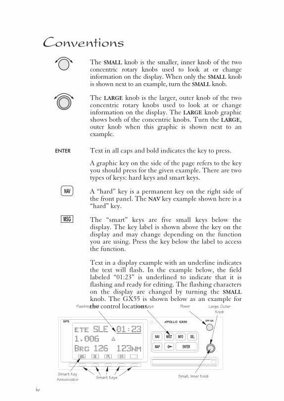
ConventionsThe SMALL knob is the smaller, inner knob of the twoconcentric rotary knobs used to look at or changeinformation on the display. When only the SMALL knobis shown next to an example, turn the SMALL knob.
The LARGE knob is the larger, outer knob of the twoconcentric rotary knobs used to look at or changeinformation on the display. The LARGE knob graphicshows both of the concentric knobs. Turn the LARGE,outer knob when this graphic is shown next to anexample.
ENTER Text in all caps and bold indicates the key to press.
A graphic key on the side of the page refers to the keyyou should press for the given example. There are twotypes of keys: hard keys and smart keys.
A “hard” key is a permanent key on the right side ofthe front panel. The NAV key example shown here is a“hard” key.
The “smart” keys are five small keys below thedisplay. The key label is shown above the key on thedisplay and may change depending on the functionyou are using. Press the key below the label to accessthe function.
Text in a display example with an underline indicatesthe text will flash. In the example below, the fieldlabeled “01:23” is underlined to indicate that it isflashing and ready for editing. The flashing characterson the display are changed by turning the SMALL
knob. The GX55 is shown below as an example forthe control locations.
iv
MSG
NAV
OFF-ONPOLLOA GX55GPS
NAV NRST INFO SEL
ENTERMAP D
PowerHard Keys
Smart Keys
Flashing field Large, Outer
Knob
Small, Inner Knob
ete SLE
1.006
Brg 126 123nm
01:23
“
SYSFPLDBMSG
Smart Key
Annunciator
Table of ContentsIntroduction . . . . . . . . . . . . . . . . . . . . . . . . . . . . . . . . . . . . . . . . . . . . . . 1-1
Apollo GX Features . . . . . . . . . . . . . . . . . . . . . . . . . . . . . . . . . 1-1
Display . . . . . . . . . . . . . . . . . . . . . . . . . . . . . . . . . . . . . . . . . . . . . . 1-2
External Annunciators . . . . . . . . . . . . . . . . . . . . . . . . . . . . . . . 1-3
Controls. . . . . . . . . . . . . . . . . . . . . . . . . . . . . . . . . . . . . . . . . . . . . . 1-3
Keys . . . . . . . . . . . . . . . . . . . . . . . . . . . . . . . . . . . . . . . . . . . . . . . . . 1-4
Hard Keys . . . . . . . . . . . . . . . . . . . . . . . . . . . . . . . . . . . . . . . . . . . . 1-4
“Smart” Keys . . . . . . . . . . . . . . . . . . . . . . . . . . . . . . . . . . . . . . . . . 1-5
Map Function Smart Keys . . . . . . . . . . . . . . . . . . . . . . . . . . . . . . 1-6
Communications Radio Mode Smart Keys (GX60/65) . . . . . . . . . 1-8
Apollo GX Features . . . . . . . . . . . . . . . . . . . . . . . . . . . . . . . . . . . . . . . 1-9
Getting Started . . . . . . . . . . . . . . . . . . . . . . . . . . . . . . . . . . . . . . . . . . . 2-1
Power On . . . . . . . . . . . . . . . . . . . . . . . . . . . . . . . . . . . . . . . . . . . . 2-1
Select a Waypoint. . . . . . . . . . . . . . . . . . . . . . . . . . . . . . . . . . . . . . 2-1
Finding a waypoint by name . . . . . . . . . . . . . . . . . . . . . . . . . . 2-1
Sorting waypoints by selected characters. . . . . . . . . . . . . . . . . 2-2
Looking at all waypoints in a database . . . . . . . . . . . . . . . . . . 2-3
Duplicate Identifier, City, or Facility Names . . . . . . . . . . . . . 2-4
Waypoint Information . . . . . . . . . . . . . . . . . . . . . . . . . . . . . . . . . . 2-4
Storing a Waypoint . . . . . . . . . . . . . . . . . . . . . . . . . . . . . . . . . . . . 2-5
Finding a Nearest Waypoint. . . . . . . . . . . . . . . . . . . . . . . . . . . . . 2-6
Flying Direct-To a Waypoint . . . . . . . . . . . . . . . . . . . . . . . . . . . . 2-7
Create a Flight Plan . . . . . . . . . . . . . . . . . . . . . . . . . . . . . . . . . . . . 2-8
Activating a Flight Plan . . . . . . . . . . . . . . . . . . . . . . . . . . . . . . . . . 2-9
Using the Moving Map . . . . . . . . . . . . . . . . . . . . . . . . . . . . . . . . 2-10
Navigation Basics . . . . . . . . . . . . . . . . . . . . . . . . . . . . . . . . . . . . . . . . . 3-1
About the Navigation Function . . . . . . . . . . . . . . . . . . . . . . . . . . 3-1
About the Navigation Function Displays . . . . . . . . . . . . . . . . . . 3-1
Nav Home Page . . . . . . . . . . . . . . . . . . . . . . . . . . . . . . . . . . . . . . . 3-1
Autonav . . . . . . . . . . . . . . . . . . . . . . . . . . . . . . . . . . . . . . . . . . . . . . 3-2
Relative Bearing Indicator . . . . . . . . . . . . . . . . . . . . . . . . . . . . . . . 3-3
Nav Pages . . . . . . . . . . . . . . . . . . . . . . . . . . . . . . . . . . . . . . . . . . . . 3-3
Estimated Time En Route (Ete) . . . . . . . . . . . . . . . . . . . . . . . 3-4
Bearing (Brg) . . . . . . . . . . . . . . . . . . . . . . . . . . . . . . . . . . . . . . . 3-4
Table of Contents
v
Range (Rge) . . . . . . . . . . . . . . . . . . . . . . . . . . . . . . . . . . . . . . . . 3-4
Course Deviation Indicator (CDI) and Distance Off Track. 3-5
TO/FROM Indicator . . . . . . . . . . . . . . . . . . . . . . . . . . . . . . . . 3-6
Desired Track (Dtk) . . . . . . . . . . . . . . . . . . . . . . . . . . . . . . . . . 3-6
Leg (FROM-TO) Distance . . . . . . . . . . . . . . . . . . . . . . . . . . . 3-6
Track (Trk) Angle . . . . . . . . . . . . . . . . . . . . . . . . . . . . . . . . . . . 3-7
Track Angle Error (Tae). . . . . . . . . . . . . . . . . . . . . . . . . . . . . . 3-7
Ground Speed (GS) . . . . . . . . . . . . . . . . . . . . . . . . . . . . . . . . . 3-7
Minimum Safe Altitude (MSA) . . . . . . . . . . . . . . . . . . . . . . . . 3-8
Minimum En Route Safe Altitude (MESA) . . . . . . . . . . . . . . 3-8
Flight Time . . . . . . . . . . . . . . . . . . . . . . . . . . . . . . . . . . . . . . . . 3-9
Time UTC . . . . . . . . . . . . . . . . . . . . . . . . . . . . . . . . . . . . . . . . . 3-9
Estimated Time of Arrival (ETA) . . . . . . . . . . . . . . . . . . . . . . 3-9
Nearest Waypoint & Airspace Search. . . . . . . . . . . . . . . . . . . . . . 3-9
Controlled Special Use Airspace. . . . . . . . . . . . . . . . . . . . . . . . . 3-13
Altitude Assist (VNAV) . . . . . . . . . . . . . . . . . . . . . . . . . . . . . . . 3-14
Parallel Track Offset . . . . . . . . . . . . . . . . . . . . . . . . . . . . . . . . . . 3-19
GPS Position . . . . . . . . . . . . . . . . . . . . . . . . . . . . . . . . . . . . . . . . 3-21
Countdown Timer . . . . . . . . . . . . . . . . . . . . . . . . . . . . . . . . . . . . 3-22
Arc Assist . . . . . . . . . . . . . . . . . . . . . . . . . . . . . . . . . . . . . . . . . . . . 3-23
Waypoint Distance Page . . . . . . . . . . . . . . . . . . . . . . . . . . . . . . . 3-25
Waypoint ETE Page . . . . . . . . . . . . . . . . . . . . . . . . . . . . . . . . . . 3-25
From-To-Next Waypoint ETA Page. . . . . . . . . . . . . . . . . . . . . 3-25
From/To/Next Waypoint . . . . . . . . . . . . . . . . . . . . . . . . . . . . . . 3-26
Creating FROM/TO/NEXT Waypoints . . . . . . . . . . . . . . . 3-26
Placing the TO Waypoint on Hold . . . . . . . . . . . . . . . . . . . . 3-30
Using Direct-To . . . . . . . . . . . . . . . . . . . . . . . . . . . . . . . . . . . . . . 3-31
Direct-To Examples. . . . . . . . . . . . . . . . . . . . . . . . . . . . . . . . . . . 3-32
Center the CDI . . . . . . . . . . . . . . . . . . . . . . . . . . . . . . . . . . . . 3-32
Enter a New Waypoint into a Flight Plan . . . . . . . . . . . . . . 3-33
Direct-To OBS. . . . . . . . . . . . . . . . . . . . . . . . . . . . . . . . . . . . . . . 3-35
Turn Anticipation . . . . . . . . . . . . . . . . . . . . . . . . . . . . . . . . . . . . 3-36
Standard Turn Operation. . . . . . . . . . . . . . . . . . . . . . . . . . . . 3-36
Wind and Turn Anticipation . . . . . . . . . . . . . . . . . . . . . . . . . 3-37
GPSS . . . . . . . . . . . . . . . . . . . . . . . . . . . . . . . . . . . . . . . . . . . . . . . 3-37
Standard GPSS Operation . . . . . . . . . . . . . . . . . . . . . . . . . . . 3-37
vi
Table of Contents
Approach GPSS Operation . . . . . . . . . . . . . . . . . . . . . . . . . . 3-38
GPSS Rules . . . . . . . . . . . . . . . . . . . . . . . . . . . . . . . . . . . . . . . 3-38
Tuned Station. . . . . . . . . . . . . . . . . . . . . . . . . . . . . . . . . . . . . . . . 3-39
Tuning to a VOR. . . . . . . . . . . . . . . . . . . . . . . . . . . . . . . . . . . 3-39
Tuning to a Localizer . . . . . . . . . . . . . . . . . . . . . . . . . . . . . . . 3-40
Moving Map Functions . . . . . . . . . . . . . . . . . . . . . . . . . . . . . . . . . . . . 4-1
Full Screen Map. . . . . . . . . . . . . . . . . . . . . . . . . . . . . . . . . . . . . . . 4-1
Controls. . . . . . . . . . . . . . . . . . . . . . . . . . . . . . . . . . . . . . . . . . . . . . 4-2
Waypoint Type Keys. . . . . . . . . . . . . . . . . . . . . . . . . . . . . . . . . 4-2
Waypoint List Keys . . . . . . . . . . . . . . . . . . . . . . . . . . . . . . . . . . 4-2
Waypoint Scan Key . . . . . . . . . . . . . . . . . . . . . . . . . . . . . . . . . . 4-3
Map Scale . . . . . . . . . . . . . . . . . . . . . . . . . . . . . . . . . . . . . . . . . . 4-3
Map and Nav Info . . . . . . . . . . . . . . . . . . . . . . . . . . . . . . . . . . . . . 4-3
Map Setup. . . . . . . . . . . . . . . . . . . . . . . . . . . . . . . . . . . . . . . . . . . . 4-4
Route Line . . . . . . . . . . . . . . . . . . . . . . . . . . . . . . . . . . . . . . . . . 4-4
Map Orient. . . . . . . . . . . . . . . . . . . . . . . . . . . . . . . . . . . . . . . . . 4-5
Map Reference . . . . . . . . . . . . . . . . . . . . . . . . . . . . . . . . . . . . . . 4-6
Identifier and Waypoint Type Selection . . . . . . . . . . . . . . . . . 4-6
Track History. . . . . . . . . . . . . . . . . . . . . . . . . . . . . . . . . . . . . . . 4-8
Airspace Setup . . . . . . . . . . . . . . . . . . . . . . . . . . . . . . . . . . . . . 4-10
Airspace Buffers . . . . . . . . . . . . . . . . . . . . . . . . . . . . . . . . . . . . 4-11
ATC Ring Selection . . . . . . . . . . . . . . . . . . . . . . . . . . . . . . . . 4-12
Airspace Selections . . . . . . . . . . . . . . . . . . . . . . . . . . . . . . . . . 4-12
Search and Rescue . . . . . . . . . . . . . . . . . . . . . . . . . . . . . . . . . . . . 4-14
Search and Rescue Map Description . . . . . . . . . . . . . . . . . . . 4-14
Grid Line Display . . . . . . . . . . . . . . . . . . . . . . . . . . . . . . . . . . 4-15
US Grid Type . . . . . . . . . . . . . . . . . . . . . . . . . . . . . . . . . . . . . 4-15
Basic Grid Type. . . . . . . . . . . . . . . . . . . . . . . . . . . . . . . . . . . . 4-16
Search and Rescue Map Setup Page . . . . . . . . . . . . . . . . . . . 4-16
Set the SAR Position (Basic Grid Type) . . . . . . . . . . . . . . . . 4-18
Selecting A Pattern . . . . . . . . . . . . . . . . . . . . . . . . . . . . . . . . . 4-20
Parallel Line Search Pattern. . . . . . . . . . . . . . . . . . . . . . . . . . 4-21
Creeping Line Search Pattern . . . . . . . . . . . . . . . . . . . . . . . . 4-23
Expanding Square Search Pattern. . . . . . . . . . . . . . . . . . . . . 4-26
Mark A Position. . . . . . . . . . . . . . . . . . . . . . . . . . . . . . . . . . . . 4-28
Create A User Waypoint By US Grid . . . . . . . . . . . . . . . . . . 4-29
vii
Table of Contents
Fly Direct To A US Grid . . . . . . . . . . . . . . . . . . . . . . . . . . . . 4-30
Create a User Waypoint By Basic Grid . . . . . . . . . . . . . . . . . 4-30
Fly Direct To A Basic Grid. . . . . . . . . . . . . . . . . . . . . . . . . . . 4-32
Setting Up A Search Pattern. . . . . . . . . . . . . . . . . . . . . . . . . . 4-32
Waypoint Database . . . . . . . . . . . . . . . . . . . . . . . . . . . . . . . . . . . . . . . . 5-1
Waypoint Information . . . . . . . . . . . . . . . . . . . . . . . . . . . . . . . . . . 5-1
Available Waypoint Information . . . . . . . . . . . . . . . . . . . . . . . . . 5-1
Getting Information About A Waypoint . . . . . . . . . . . . . . . . . . . 5-3
Airport Info Pages . . . . . . . . . . . . . . . . . . . . . . . . . . . . . . . . . . . . . 5-5
Create User Waypoint by Lat/Lon . . . . . . . . . . . . . . . . . . . . . . . . 5-9
Create User Waypoint by Radial/Distance . . . . . . . . . . . . . . . . 5-10
Update User Wpt with Present Pos . . . . . . . . . . . . . . . . . . . . . . 5-12
Delete User Waypoint . . . . . . . . . . . . . . . . . . . . . . . . . . . . . . . . . 5-12
Modify User Waypoint . . . . . . . . . . . . . . . . . . . . . . . . . . . . . . . . 5-13
Creating Waypoint Comments. . . . . . . . . . . . . . . . . . . . . . . . . . 5-14
Deleting Waypoint Comments . . . . . . . . . . . . . . . . . . . . . . . . . . 5-15
Update User Waypoint . . . . . . . . . . . . . . . . . . . . . . . . . . . . . . . . 5-16
Datacard . . . . . . . . . . . . . . . . . . . . . . . . . . . . . . . . . . . . . . . . . . . . 5-16
RNAV Waypoints. . . . . . . . . . . . . . . . . . . . . . . . . . . . . . . . . . . . . 5-16
Flight Plan Functions . . . . . . . . . . . . . . . . . . . . . . . . . . . . . . . . . . . . . 6-1
Flight Plan Pages . . . . . . . . . . . . . . . . . . . . . . . . . . . . . . . . . . . . . . 6-1
Creating a Flight Plan . . . . . . . . . . . . . . . . . . . . . . . . . . . . . . . . . . 6-2
Flight Plan Sequencing . . . . . . . . . . . . . . . . . . . . . . . . . . . . . . . . . 6-5
Flight Plan Leg Information. . . . . . . . . . . . . . . . . . . . . . . . . . . . . 6-6
Manual Leg Activation . . . . . . . . . . . . . . . . . . . . . . . . . . . . . . . . . 6-9
Flight Plan Editing . . . . . . . . . . . . . . . . . . . . . . . . . . . . . . . . . . . 6-10
Flight Plan Options . . . . . . . . . . . . . . . . . . . . . . . . . . . . . . . . . . . 6-14
Activate . . . . . . . . . . . . . . . . . . . . . . . . . . . . . . . . . . . . . . . . . . . 6-14
Rev Activate . . . . . . . . . . . . . . . . . . . . . . . . . . . . . . . . . . . . . . . 6-15
Reactivate . . . . . . . . . . . . . . . . . . . . . . . . . . . . . . . . . . . . . . . . . 6-15
Rename. . . . . . . . . . . . . . . . . . . . . . . . . . . . . . . . . . . . . . . . . . . 6-15
Copy Plan. . . . . . . . . . . . . . . . . . . . . . . . . . . . . . . . . . . . . . . . . 6-16
Estimated Ground Speed . . . . . . . . . . . . . . . . . . . . . . . . . . . 6-16
Clear Waypoints . . . . . . . . . . . . . . . . . . . . . . . . . . . . . . . . . . . 6-17
Reverse Flight Plan . . . . . . . . . . . . . . . . . . . . . . . . . . . . . . . . . 6-17
Estimated Fuel Flow. . . . . . . . . . . . . . . . . . . . . . . . . . . . . . . . 6-17
viii
Table of Contents
Delete Plan. . . . . . . . . . . . . . . . . . . . . . . . . . . . . . . . . . . . . . . . 6-18
Hold . . . . . . . . . . . . . . . . . . . . . . . . . . . . . . . . . . . . . . . . . . . . . 6-18
Holding Patterns (GX50/60) . . . . . . . . . . . . . . . . . . . . . . . . . 6-19
Continue. . . . . . . . . . . . . . . . . . . . . . . . . . . . . . . . . . . . . . . . . . 6-21
Load Approach (GX50/60 Only) . . . . . . . . . . . . . . . . . . . . . . 6-22
Change Approach (GX50/60 Only) . . . . . . . . . . . . . . . . . . . 6-22
Unload Approach (GX50/60 Only). . . . . . . . . . . . . . . . . . . . 6-22
Enable Approach (GX50/60 Only) . . . . . . . . . . . . . . . . . . . . 6-23
Disable Approach (GX50/60 Only). . . . . . . . . . . . . . . . . . . . 6-23
Destination Waypoint Information . . . . . . . . . . . . . . . . . . . . . . 6-23
Flight Plan Comments . . . . . . . . . . . . . . . . . . . . . . . . . . . . . . . . 6-23
Saving an Active Flight Plan. . . . . . . . . . . . . . . . . . . . . . . . . . . . 6-24
System Functions . . . . . . . . . . . . . . . . . . . . . . . . . . . . . . . . . . . . . . . . . 7-1
Navigation Information. . . . . . . . . . . . . . . . . . . . . . . . . . . . . . . . . 7-1
Autonav Time . . . . . . . . . . . . . . . . . . . . . . . . . . . . . . . . . . . . . . 7-1
Navigation Mode Programmable and Autonav Pages. . . . . . 7-2
Customizing Navigation Pages . . . . . . . . . . . . . . . . . . . . . . . . 7-2
Selecting Autonav Pages . . . . . . . . . . . . . . . . . . . . . . . . . . . . . . 7-4
Restoring Default Nav Pages . . . . . . . . . . . . . . . . . . . . . . . . . . 7-4
Lat/Lon Units . . . . . . . . . . . . . . . . . . . . . . . . . . . . . . . . . . . . . . 7-4
Setting Units of Measurement . . . . . . . . . . . . . . . . . . . . . . . . . 7-6
Magnetic Variation . . . . . . . . . . . . . . . . . . . . . . . . . . . . . . . . . . 7-7
Flight Timer Trigger. . . . . . . . . . . . . . . . . . . . . . . . . . . . . . . . . 7-8
Direct-To Entry Options . . . . . . . . . . . . . . . . . . . . . . . . . . . . . 7-8
CDI Scaling . . . . . . . . . . . . . . . . . . . . . . . . . . . . . . . . . . . . . . . 7-10
System Information . . . . . . . . . . . . . . . . . . . . . . . . . . . . . . . . . . . 7-11
Date and Time. . . . . . . . . . . . . . . . . . . . . . . . . . . . . . . . . . . . . 7-11
Software Version . . . . . . . . . . . . . . . . . . . . . . . . . . . . . . . . . . . 7-12
Fuel Measure Units (GX50/60 Only) . . . . . . . . . . . . . . . . . . 7-13
Barometric Measure Units (GX50/60 Only) . . . . . . . . . . . . 7-14
Test Display . . . . . . . . . . . . . . . . . . . . . . . . . . . . . . . . . . . . . . . 7-14
Display Brightness. . . . . . . . . . . . . . . . . . . . . . . . . . . . . . . . . . 7-14
Viewing Owner Information . . . . . . . . . . . . . . . . . . . . . . . . . 7-15
Editing Owner Information . . . . . . . . . . . . . . . . . . . . . . . . . . 7-16
GPS Sensor . . . . . . . . . . . . . . . . . . . . . . . . . . . . . . . . . . . . . . . . . . 7-17
Miscellaneous Sensors . . . . . . . . . . . . . . . . . . . . . . . . . . . . . . . . 7-20
ix
Encoding Altimeter . . . . . . . . . . . . . . . . . . . . . . . . . . . . . . . . . . . 7-20
Air Data Info. . . . . . . . . . . . . . . . . . . . . . . . . . . . . . . . . . . . . . . . . 7-21
Air Speed . . . . . . . . . . . . . . . . . . . . . . . . . . . . . . . . . . . . . . . . . 7-21
Air Temperature . . . . . . . . . . . . . . . . . . . . . . . . . . . . . . . . . . . 7-21
Altitude and Rate of Climb. . . . . . . . . . . . . . . . . . . . . . . . . . . 7-21
Heading and Turn Rate . . . . . . . . . . . . . . . . . . . . . . . . . . . . . 7-21
Wind Direction and Speed . . . . . . . . . . . . . . . . . . . . . . . . . . . 7-22
Fuel Info . . . . . . . . . . . . . . . . . . . . . . . . . . . . . . . . . . . . . . . . . . . . 7-22
Fuel Endurance . . . . . . . . . . . . . . . . . . . . . . . . . . . . . . . . . . . . 7-22
Range, Burn Rate, and Fuel Used . . . . . . . . . . . . . . . . . . . . . 7-22
Right Engine Fuel . . . . . . . . . . . . . . . . . . . . . . . . . . . . . . . . . . 7-23
Left Engine Fuel . . . . . . . . . . . . . . . . . . . . . . . . . . . . . . . . . . . 7-23
Total Fuel. . . . . . . . . . . . . . . . . . . . . . . . . . . . . . . . . . . . . . . . . 7-23
Fuel Measure . . . . . . . . . . . . . . . . . . . . . . . . . . . . . . . . . . . . . . 7-24
Message Function . . . . . . . . . . . . . . . . . . . . . . . . . . . . . . . . . . . . . . . . . 8-1
New Messages . . . . . . . . . . . . . . . . . . . . . . . . . . . . . . . . . . . . . . . . 8-2
Old Messages . . . . . . . . . . . . . . . . . . . . . . . . . . . . . . . . . . . . . . . . . 8-2
Messages . . . . . . . . . . . . . . . . . . . . . . . . . . . . . . . . . . . . . . . . . . . . . 8-3
Approach Basics (GX50/60) . . . . . . . . . . . . . . . . . . . . . . . . . . . . . . . . . 9-1
Introduction . . . . . . . . . . . . . . . . . . . . . . . . . . . . . . . . . . . . . . . . . . 9-1
En Route. . . . . . . . . . . . . . . . . . . . . . . . . . . . . . . . . . . . . . . . . . . 9-1
Approach Transition . . . . . . . . . . . . . . . . . . . . . . . . . . . . . . . . . 9-2
Approach Active. . . . . . . . . . . . . . . . . . . . . . . . . . . . . . . . . . . . . 9-2
Approach Transition . . . . . . . . . . . . . . . . . . . . . . . . . . . . . . . . . 9-2
Waypoint Arrival Alert . . . . . . . . . . . . . . . . . . . . . . . . . . . . . . . 9-2
Approach Procedure. . . . . . . . . . . . . . . . . . . . . . . . . . . . . . . . . . . . 9-5
En Route Operations . . . . . . . . . . . . . . . . . . . . . . . . . . . . . . . . . . . 9-5
Load a Destination Airport. . . . . . . . . . . . . . . . . . . . . . . . . . . . 9-6
Load Approach Information. . . . . . . . . . . . . . . . . . . . . . . . . . . 9-7
Approach Transition Operation (Enabling Approach) . . . . . . . 9-8
Approach Active Operation. . . . . . . . . . . . . . . . . . . . . . . . . . . . . 9-11
Missed Approaches. . . . . . . . . . . . . . . . . . . . . . . . . . . . . . . . . . . . 9-13
Canceling An Approach . . . . . . . . . . . . . . . . . . . . . . . . . . . . . . . 9-15
Repeating an Approach . . . . . . . . . . . . . . . . . . . . . . . . . . . . . . . . 9-16
Selecting a Different Approach. . . . . . . . . . . . . . . . . . . . . . . . . . 9-17
Direct-To . . . . . . . . . . . . . . . . . . . . . . . . . . . . . . . . . . . . . . . . . . . 9-18
x
Table of Contents
Manually Selecting a Flight plan Leg . . . . . . . . . . . . . . . . . . . . 9-19
Flight Plan Waypoint Sequencing . . . . . . . . . . . . . . . . . . . . . . . 9-20
Procedure Turns. . . . . . . . . . . . . . . . . . . . . . . . . . . . . . . . . . . . . . 9-21
Procedure Turn at FAF. . . . . . . . . . . . . . . . . . . . . . . . . . . . . . . . 9-22
Holding Patterns . . . . . . . . . . . . . . . . . . . . . . . . . . . . . . . . . . . . . 9-24
DME Arcs (Arc Assist). . . . . . . . . . . . . . . . . . . . . . . . . . . . . . . . . 9-26
Vector to Final . . . . . . . . . . . . . . . . . . . . . . . . . . . . . . . . . . . . . . . 9-27
Navigating to a DME . . . . . . . . . . . . . . . . . . . . . . . . . . . . . . . . . 9-28
RAIM. . . . . . . . . . . . . . . . . . . . . . . . . . . . . . . . . . . . . . . . . . . . . . . 9-29
RAIM Nav Page (GX50/60 Only) . . . . . . . . . . . . . . . . . . . . . . . 9-33
Emergency (Alternate) Approach. . . . . . . . . . . . . . . . . . . . . . . . 9-35
Clear Waypoints . . . . . . . . . . . . . . . . . . . . . . . . . . . . . . . . . . . 9-35
Fly Direct-To a Nearest Airport . . . . . . . . . . . . . . . . . . . . . . 9-36
Set New Approach. . . . . . . . . . . . . . . . . . . . . . . . . . . . . . . . . . 9-36
Approach Examples. . . . . . . . . . . . . . . . . . . . . . . . . . . . . . . . . . . . . . . 9-37
Approach Example 1 - Straight In . . . . . . . . . . . . . . . . . . . . . . . 9-39
Approach Example 2 - Holding at IFAF . . . . . . . . . . . . . . . . . . 9-44
Approach Example 3 - Missed Approach. . . . . . . . . . . . . . . . . . 9-51
Approach Example 4 - VOR Reference . . . . . . . . . . . . . . . . . . . 9-56
Manual Flight Plan Leg Selection Example . . . . . . . . . . . . . . . 9-61
Approach Example 5 - DME Arc . . . . . . . . . . . . . . . . . . . . . . . 9-63
Approach Example 6 - Procedure Turn 1 . . . . . . . . . . . . . . . . . 9-66
Approach Example 7 - Procedure Turn 2 . . . . . . . . . . . . . . . . . 9-68
Using the LOC-DME Waypoint . . . . . . . . . . . . . . . . . . . . . . . . 9-69
Approach Notes . . . . . . . . . . . . . . . . . . . . . . . . . . . . . . . . . . . . . . . . . . 9-77
Comm Radio Operation . . . . . . . . . . . . . . . . . . . . . . . . . . . . . . . . . . . 10-1
Power On/Off . . . . . . . . . . . . . . . . . . . . . . . . . . . . . . . . . . . . . . . . 10-1
Volume . . . . . . . . . . . . . . . . . . . . . . . . . . . . . . . . . . . . . . . . . . . . . 10-1
Selecting Frequencies . . . . . . . . . . . . . . . . . . . . . . . . . . . . . . . . . . 10-2
Comm Mode Map Display . . . . . . . . . . . . . . . . . . . . . . . . . . . . . 10-3
Frequency Monitoring. . . . . . . . . . . . . . . . . . . . . . . . . . . . . . . . . 10-3
Recalling a Frequency . . . . . . . . . . . . . . . . . . . . . . . . . . . . . . . . . 10-4
Nearest Frequency . . . . . . . . . . . . . . . . . . . . . . . . . . . . . . . . . 10-6
INFO Frequency . . . . . . . . . . . . . . . . . . . . . . . . . . . . . . . . . . 10-6
Destination, TO, and FROM Frequencies. . . . . . . . . . . . . . 10-6
Auto Stored Frequencies (Auto) . . . . . . . . . . . . . . . . . . . . . . 10-6
xi
Table of Contents
User Stored Frequencies. . . . . . . . . . . . . . . . . . . . . . . . . . . . . 10-7
Weather Channels. . . . . . . . . . . . . . . . . . . . . . . . . . . . . . . . . . 10-7
Emergency Channel . . . . . . . . . . . . . . . . . . . . . . . . . . . . . . . . 10-8
Intercom Function . . . . . . . . . . . . . . . . . . . . . . . . . . . . . . . . . . . . 10-8
Stuck Mic . . . . . . . . . . . . . . . . . . . . . . . . . . . . . . . . . . . . . . . . . . . 10-9
Com Radio System Information (GX60/65 Only) . . . . . . . . . . 10-9
RF Signal Strength . . . . . . . . . . . . . . . . . . . . . . . . . . . . . . . . 10-10
Noise Level . . . . . . . . . . . . . . . . . . . . . . . . . . . . . . . . . . . . . . 10-10
Intercom Squelch Level Adjustment . . . . . . . . . . . . . . . . . . 10-10
Transmit Mic Selection . . . . . . . . . . . . . . . . . . . . . . . . . . . . 10-11
Intercom Level. . . . . . . . . . . . . . . . . . . . . . . . . . . . . . . . . . . . 10-11
Sidetone Level Adjustment . . . . . . . . . . . . . . . . . . . . . . . . . . 10-12
Headphone Level Adjustment . . . . . . . . . . . . . . . . . . . . . . . . 10-12
Start Up Displays. . . . . . . . . . . . . . . . . . . . . . . . . . . . . . . . . . . . . . . . . 11-1
Startup Bypass . . . . . . . . . . . . . . . . . . . . . . . . . . . . . . . . . . . . . . . 11-1
Quick Comm (GX60/65 Only). . . . . . . . . . . . . . . . . . . . . . . . . . 11-1
Comm Radio Test (GX60/65) . . . . . . . . . . . . . . . . . . . . . . . . . . 11-1
Owner Message . . . . . . . . . . . . . . . . . . . . . . . . . . . . . . . . . . . . . . 11-2
Memory Tests . . . . . . . . . . . . . . . . . . . . . . . . . . . . . . . . . . . . . . . . 11-2
Database Message . . . . . . . . . . . . . . . . . . . . . . . . . . . . . . . . . . . . 11-5
Seed Position . . . . . . . . . . . . . . . . . . . . . . . . . . . . . . . . . . . . . . . . 11-5
Entering a Seed Position . . . . . . . . . . . . . . . . . . . . . . . . . . . . . . . 11-5
IFR Output Tests . . . . . . . . . . . . . . . . . . . . . . . . . . . . . . . . . . . . . 11-8
Checking GPS Signal Strength . . . . . . . . . . . . . . . . . . . . . . . . 11-11
Flight Simulator . . . . . . . . . . . . . . . . . . . . . . . . . . . . . . . . . . . . . . . . . 12-1
About the Flight Simulator . . . . . . . . . . . . . . . . . . . . . . . . . . . . . 12-1
Removing and Replacing the Apollo GX. . . . . . . . . . . . . . . . . . 12-2
Starting the Flight Simulation . . . . . . . . . . . . . . . . . . . . . . . . . . 12-3
Flight Simulator Operations . . . . . . . . . . . . . . . . . . . . . . . . . . . . 12-4
Troubleshooting . . . . . . . . . . . . . . . . . . . . . . . . . . . . . . . . . . . . . . . . . 13-1
Contacting the Factory . . . . . . . . . . . . . . . . . . . . . . . . . . . . . . . . 13-1
To Ensure Trouble Free Operation . . . . . . . . . . . . . . . . . . . . . . 13-2
Battery Replacement . . . . . . . . . . . . . . . . . . . . . . . . . . . . . . . . . . 13-2
If You Have A Problem . . . . . . . . . . . . . . . . . . . . . . . . . . . . . . . . 13-2
GPS Navigation . . . . . . . . . . . . . . . . . . . . . . . . . . . . . . . . . . . . . . . . . . 14-1
Glossary . . . . . . . . . . . . . . . . . . . . . . . . . . . . . . . . . . . . . . . . . . . . . . . . 15-1
xii
Table of Contents
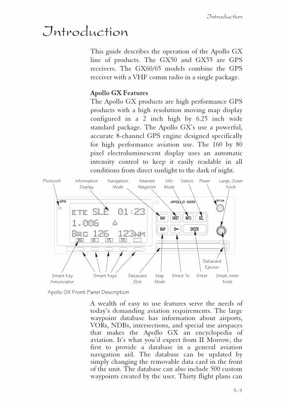
IntroductionThis guide describes the operation of the Apollo GX
line of products. The GX50 and GX55 are GPS
receivers. The GX60/65 models combine the GPS
receiver with a VHF comm radio in a single package.
Apollo GX FeaturesThe Apollo GX products are high performance GPS
products with a high resolution moving map display
configured in a 2 inch high by 6.25 inch wide
standard package. The Apollo GX’s use a powerful,
accurate 8-channel GPS engine designed specifically
for high performance aviation use. The 160 by 80
pixel electroluminescent display uses an automatic
intensity control to keep it easily readable in all
conditions from direct sunlight to the dark of night.
A wealth of easy to use features serve the needs oftoday’s demanding aviation requirements. The largewaypoint database has information about airports,VORs, NDBs, intersections, and special use airspacesthat makes the Apollo GX an encyclopedia ofaviation. It’s what you’d expect from II Morrow, thefirst to provide a database in a general aviationnavigation aid. The database can be updated bysimply changing the removable data card in the frontof the unit. The database can also include 500 customwaypoints created by the user. Thirty flight plans can
Introduction
1-1
OFF-ONPOLLOA GX55GPS
NAV NRST INFO SEL
ENTERMAP D
PowerPhotocell Nearest
Waypoint
Navigation
Mode
Direct ToMap
Mode
Smart Keys
Information
Display
Large, Outer
Knob
Small, Inner
Knob
Info
Mode
Select
EnterDatacard
Slot
ete SLE 01:23
1.006
Brg 126 123nm
“
Datacard
Ejector
SYSFPLDBMSG
Smart Key
Annunciator
Apollo GX Front Panel Description
be saved with up to twenty legs for setting up customtailored routes. The detailed Navigation informationdisplays are also customizable and can be set toautomatically scroll through the desired information.The Nearest/Emergency Search feature, invented byII Morrow (UPS Aviation Technologies), makes iteasy to react to an emergency or change your activeflight plan.
GX55The GX55 is designed to be simple slide-in,
pin-compatible replacement for panel-mounted
Apollo Loran and Flybuddy GPS receivers. The
GX55 connectors and antenna footprint are the same
as the Apollo Loran and Flybuddy GPS receivers.
The GX55 is TSO-C129 Class A2 authorized for IFR
en route and terminal operation.
GX50The Apollo GX50 GPS receiver possesses all of the
performance features of the GX55, plus more. The
GX50 is TSO-C129a Class A1 authorized for IFR
non-precision approach operation. The GX50 uses
the same tray size, but different connections on the
back to allow for approach capabilities.
GX60The Apollo GX60 combines the physical package of
the GX50 GPS receiver with a revolutionary VHF
Comm transceiver. All of this without the
requirement for external cooling.
GX65The Apollo GX65 possesses the same features as the
GX60, except it is not certified for IFR approaches.
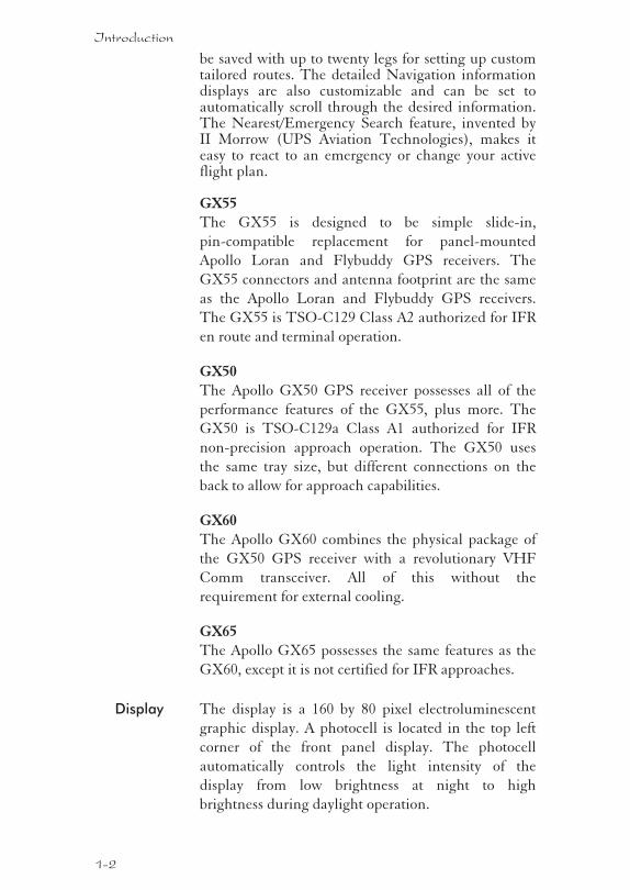
Display The display is a 160 by 80 pixel electroluminescent
graphic display. A photocell is located in the top left
corner of the front panel display. The photocell
automatically controls the light intensity of the
display from low brightness at night to high
brightness during daylight operation.
1-2
Introduction
External AnnunciatorsWhen external indicators are installed, the Apollo GX
will also provide an external indication when Parallel
Track (PTK) is activated or a Message (MSG) is
received. The GX50/60 also have external
annunciator controls for OBS/Hold and Approach
Active. “Hold” refers to suspending waypoint
sequencing.
Controls The Apollo GX uses a variety of controls to manage
the features. The controls include a power knob,
dual-concentric knobs (called LARGE and SMALL),
hard keys, and “smart” keys.
Power KnobThe knob on the top right side of the Apollo GX
controls power on/off. Rotate the knob clockwise
(CW) past the detent to turn the power on. Rotate the
knob fully counterclockwise to turn the power off.
Full rotation and the push-pull capabilities are only
used in the GX60/65.
Power/Volume/Squelch Knob(GX60/65)The knob on the right side of the GX60/65 controls
power on/off, volume, and squelch test. Rotate the knob
clockwise (CW) past the detent to turn the power on.
Continue rotating the knob to the right to increase
speaker and headphone amplifier volume level. Rotate
the knob to the left to reduce the volume level. Pull the
knob out to disable automatic squelch.
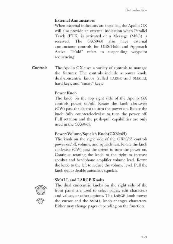
SMALL and LARGE KnobsThe dual concentric knobs on the right side of the
front panel are used to select pages, edit characters
and values, or other options. The LARGE knob moves
the cursor and the SMALL knob changes characters.
Either may change pages depending on the function.
1-3
Introduction
Keys There are two types of keys that allow you access tothe functions in your Apollo GX: permanent “hard”keys and displayed “smart” keys. Seven back lightedpermanent keys are used to reach the functions orperform other operations of the Apollo GX. The“smart” key labels are shown on the bottom of thedisplay. There are two categories of “smart” keys:those available for the Map function and thoseavailable at all other times. Press the key below thelabel to use the displayed function. Press a functionkey once to go to the last page viewed or twice to go toits “home” page.
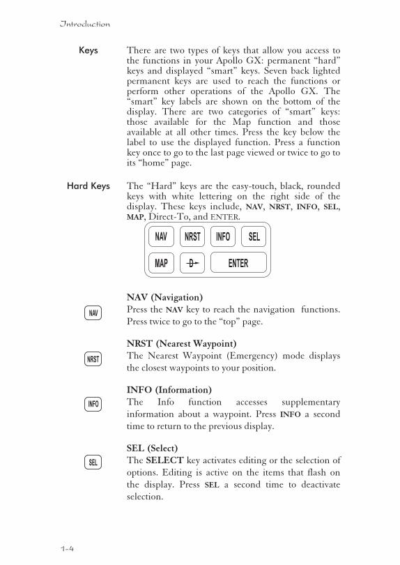
Hard Keys The “Hard” keys are the easy-touch, black, roundedkeys with white lettering on the right side of thedisplay. These keys include, NAV, NRST, INFO, SEL,MAP, Direct-To, and ENTER.
NAV (Navigation)Press the NAV key to reach the navigation functions.
Press twice to go to the “top” page.
NRST (Nearest Waypoint)The Nearest Waypoint (Emergency) mode displays
the closest waypoints to your position.
INFO (Information)The Info function accesses supplementary
information about a waypoint. Press INFO a second
time to return to the previous display.
SEL (Select)The SELECT key activates editing or the selection of
options. Editing is active on the items that flash on
the display. Press SEL a second time to deactivate
selection.
1-4
Introduction
NRST
NAV
SEL
INFO
NAV NRST INFO SEL
ENTERMAP D
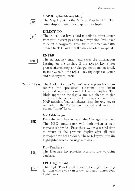
MAP (Graphic Moving Map)The Map key starts the Moving Map function. The
entire display is used as a graphic map display.
DIRECT-TOThe DIRECT-TO key is used to define a direct course
from your present position to a waypoint. Press once
to select a waypoint. Press twice to enter an OBS
desired track To or From the current active waypoint.
ENTERThe ENTER key enters and saves the information
flashing on the display. If the ENTER key is not
pressed after editing, any changes made are not saved.
In the GX60/65, the ENTER key flip/flops the Active
and Standby frequencies.
“Smart” Keys The Apollo GX uses “smart” keys to provide customcontrols for specialized functions. Five smallunlabeled keys are located below the display. Thelabels appear on the display and can change to giveextra controls for the active function, such as in theMAP function. You can always press the NAV key togo back to the Navigation function and view thenormal “smart” keys.
MSG (Message)Press the MSG key to reach the Message functions.
The MSG annunciator will flash when a new
message is provided. Press the MSG key a second time
to return to the previous display after all new
messages have been viewed. The MSG key will remain
highlighted when a message remains.
DB (Database)The Database key provides access to the waypoint
database.
FPL (Flight Plan)The Flight Plan key takes you to the flight planningfunction where you can create, edit, and control yourflight plans.
1-5
Introduction
MSG
ENTER
FPL
DB
MAP
D
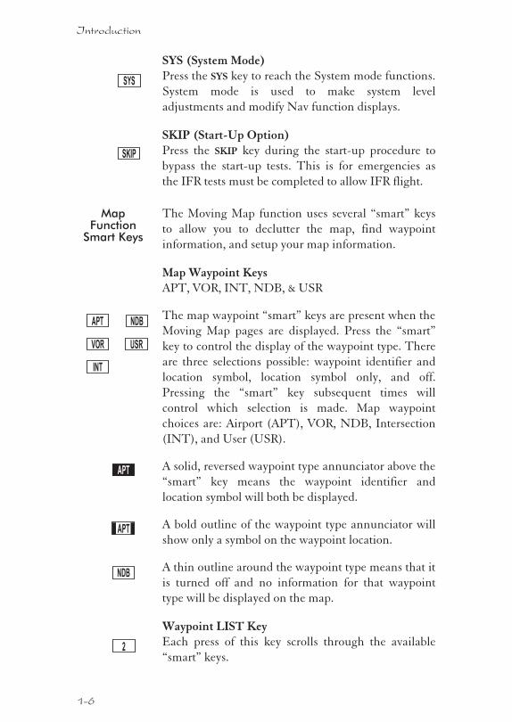
SYS (System Mode)Press the SYS key to reach the System mode functions.
System mode is used to make system level
adjustments and modify Nav function displays.
SKIP (Start-Up Option)Press the SKIP key during the start-up procedure to
bypass the start-up tests. This is for emergencies as
the IFR tests must be completed to allow IFR flight.
MapFunction
Smart Keys
The Moving Map function uses several “smart” keys
to allow you to declutter the map, find waypoint
information, and setup your map information.
Map Waypoint KeysAPT, VOR, INT, NDB, & USR
The map waypoint “smart” keys are present when the
Moving Map pages are displayed. Press the “smart”
key to control the display of the waypoint type. There
are three selections possible: waypoint identifier and
location symbol, location symbol only, and off.
Pressing the “smart” key subsequent times will
control which selection is made. Map waypoint
choices are: Airport (APT), VOR, NDB, Intersection
(INT), and User (USR).
A solid, reversed waypoint type annunciator above the
“smart” key means the waypoint identifier and
location symbol will both be displayed.
A bold outline of the waypoint type annunciator will
show only a symbol on the waypoint location.
A thin outline around the waypoint type means that it
is turned off and no information for that waypoint
type will be displayed on the map.
Waypoint LIST KeyEach press of this key scrolls through the available
“smart” keys.
1-6
Introduction
APT
APT
NDB
NDB
INT
VOR
APT
USR
2
SKIP
SYS
Waypoint SCAN KeyWhen the SCAN key is active (highlighted) in the
Moving Map display, turning the LARGE knob will
move between the nearest airports. You can then press
INFO to view information about that airport. In an
emergency press DIRECT-TO and ENTER to fly direct
to the highlighted airport. Press the SCAN key again to
return the LARGE knob to normal operation.
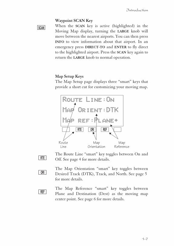
Map Setup KeysThe Map Setup page displays three “smart” keys that
provide a short cut for customizing your moving map.
The Route Line “smart” key toggles between On and
Off. See page 4 for more details.
The Map Orientation “smart” key toggles between
Desired Track (DTK), Track, and North. See page 5
for more details.
The Map Reference “smart” key toggles between
Plane and Destination (Dest) as the moving map
center point. See page 6 for more details.
1-7
Introduction
RTE
ORI
REF
Route Line:On
Map Orient:DTK
Map ref:Plane·
MapReference
RTE ORI REF
MapOrientation
RouteLine
SCAN
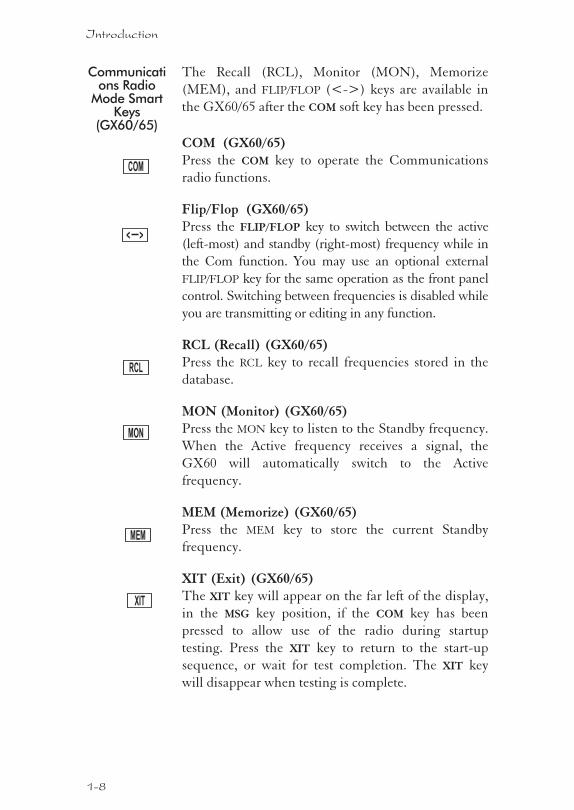
Communications Radio
Mode SmartKeys
(GX60/65)
The Recall (RCL), Monitor (MON), Memorize
(MEM), and FLIP/FLOP (<->) keys are available in
the GX60/65 after the COM soft key has been pressed.
COM (GX60/65)Press the COM key to operate the Communications
radio functions.
Flip/Flop (GX60/65)Press the FLIP/FLOP key to switch between the active
(left-most) and standby (right-most) frequency while in
the Com function. You may use an optional external
FLIP/FLOP key for the same operation as the front panel
control. Switching between frequencies is disabled while
you are transmitting or editing in any function.
RCL (Recall) (GX60/65)Press the RCL key to recall frequencies stored in the
database.
MON (Monitor) (GX60/65)Press the MON key to listen to the Standby frequency.
When the Active frequency receives a signal, the
GX60 will automatically switch to the Active
frequency.
MEM (Memorize) (GX60/65)Press the MEM key to store the current Standby
frequency.
XIT (Exit) (GX60/65)The XIT key will appear on the far left of the display,
in the MSG key position, if the COM key has been
pressed to allow use of the radio during startup
testing. Press the XIT key to return to the start-up
sequence, or wait for test completion. The XIT key
will disappear when testing is complete.
1-8
Introduction
RCL
MON
COM
< >
MEM
XIT
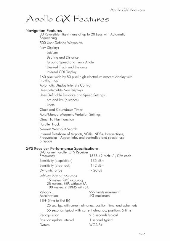
Apollo GX FeaturesNavigation Features
30 Reversible Flight Plans of up to 20 Legs with AutomaticSequencing
500 User-Defined Waypoints
Nav Displays
Lat/Lon
Bearing and Distance
Ground Speed and Track Angle
Desired Track and Distance
Internal CDI Display
160 pixel wide by 80 pixel high electroluminescent display withmoving map
Automatic Display Intensity Control
User-Selectable Nav Displays
User-Definable Distance and Speed Settings:
nm and km (distance)
knots
Clock and Countdown Timer
Auto/Manual Magnetic Variation Settings
Direct-To Nav Function
Parallel Track
Nearest Waypoint Search
Internal Database of Airports, VORs, NDBs, Intersections,Frequencies, Airport Info, and controlled and special useairspace
GPS Receiver Performance Specifications8-Channel Parallel GPS ReceiverFrequency 1575.42 MHz L1, C/A code
Sensitivity (acquisition) -135 dBm
Sensitivity (drop lock) -142 dBm
Dynamic range > 20 dB
Lat/Lon position accuracy
15 meters RMS accuracy25 meters, SEP, without SA100 meters 2 DRMS with SA
Velocity 999 knots maximumAcceleration 4G maximum
TTFF (time to first fix)
25 sec. typ. with current almanac, position, time, and ephemeris
55 seconds typical with current almanac, position, & time
Reacquisition 2.5 seconds typical
Position update interval 1 second typical
Datum WGS-84
1-9
Apollo GX Features
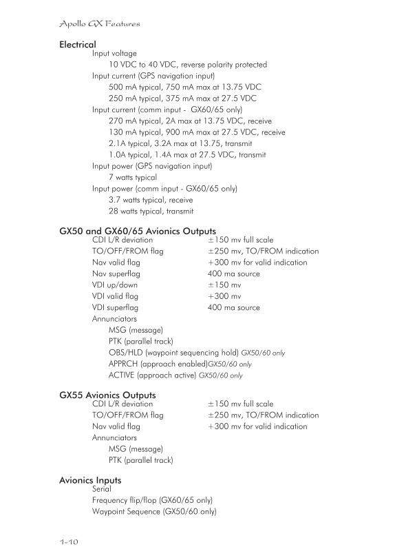
ElectricalInput voltage
10 VDC to 40 VDC, reverse polarity protected
Input current (GPS navigation input)
500 mA typical, 750 mA max at 13.75 VDC
250 mA typical, 375 mA max at 27.5 VDC
Input current (comm input - GX60/65 only)
270 mA typical, 2A max at 13.75 VDC, receive
130 mA typical, 900 mA max at 27.5 VDC, receive
2.1A typical, 3.2A max at 13.75, transmit
1.0A typical, 1.4A max at 27.5 VDC, transmit
Input power (GPS navigation input)
7 watts typical
Input power (comm input - GX60/65 only)
3.7 watts typical, receive
28 watts typical, transmit
GX50 and GX60/65 Avionics OutputsCDI L/R deviation ±150 mv full scale
TO/OFF/FROM flag ±250 mv, TO/FROM indication
Nav valid flag +300 mv for valid indication
Nav superflag 400 ma source
VDI up/down ±150 mv
VDI valid flag +300 mv
VDI superflag 400 ma source
Annunciators
MSG (message)
PTK (parallel track)
OBS/HLD (waypoint sequencing hold) GX50/60 only
APPRCH (approach enabled)GX50/60 only
ACTIVE (approach active) GX50/60 only
GX55 Avionics OutputsCDI L/R deviation ±150 mv full scale
TO/OFF/FROM flag ±250 mv, TO/FROM indication
Nav valid flag +300 mv for valid indication
Annunciators
MSG (message)
PTK (parallel track)
Avionics InputsSerial
Frequency flip/flop (GX60/65 only)
Waypoint Sequence (GX50/60 only)
1-10
Apollo GX Features
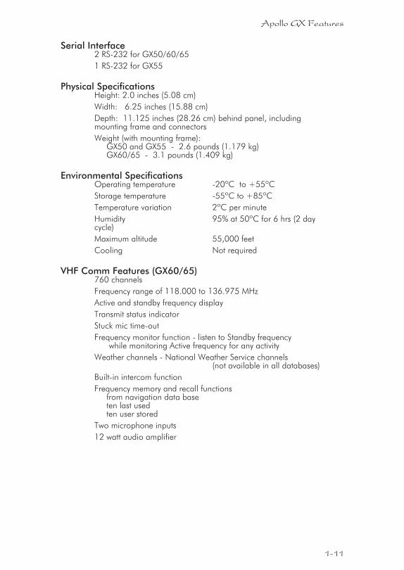
Serial Interface2 RS-232 for GX50/60/65
1 RS-232 for GX55
Physical SpecificationsHeight: 2.0 inches (5.08 cm)
Width: 6.25 inches (15.88 cm)
Depth: 11.125 inches (28.26 cm) behind panel, includingmounting frame and connectors
Weight (with mounting frame):GX50 and GX55 - 2.6 pounds (1.179 kg)GX60/65 - 3.1 pounds (1.409 kg)
Environmental SpecificationsOperating temperature -20ºC to +55ºC
Storage temperature -55ºC to +85ºC
Temperature variation 2ºC per minute
Humidity 95% at 50ºC for 6 hrs (2 daycycle)
Maximum altitude 55,000 feet
Cooling Not required
VHF Comm Features (GX60/65)760 channels
Frequency range of 118.000 to 136.975 MHz
Active and standby frequency display
Transmit status indicator
Stuck mic time-out
Frequency monitor function - listen to Standby frequencywhile monitoring Active frequency for any activity
Weather channels - National Weather Service channels(not available in all databases)
Built-in intercom function
Frequency memory and recall functionsfrom navigation data baseten last usedten user stored
Two microphone inputs
12 watt audio amplifier
1-11
Apollo GX Features
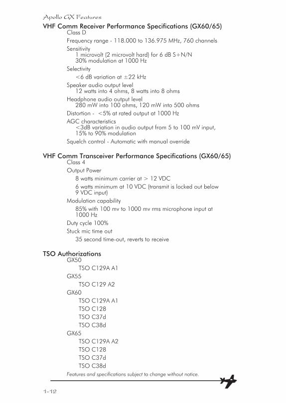
VHF Comm Receiver Performance Specifications (GX60/65)Class D
Frequency range - 118.000 to 136.975 MHz, 760 channels
Sensitivity1 microvolt (2 microvolt hard) for 6 dB S+N/N30% modulation at 1000 Hz
Selectivity
<6 dB variation at ±22 kHz
Speaker audio output level12 watts into 4 ohms, 8 watts into 8 ohms
Headphone audio output level280 mW into 100 ohms, 120 mW into 500 ohms
Distortion - <5% at rated output at 1000 Hz
AGC characteristics<3dB variation in audio output from 5 to 100 mV input,15% to 90% modulation
Squelch control - Automatic with manual override
VHF Comm Transceiver Performance Specifications (GX60/65)Class 4
Output Power
8 watts minimum carrier at > 12 VDC
6 watts minimum at 10 VDC (transmit is locked out below9 VDC input)
Modulation capability
85% with 100 mv to 1000 mv rms microphone input at1000 Hz
Duty cycle 100%
Stuck mic time out
35 second time-out, reverts to receive
TSO AuthorizationsGX50
TSO C129A A1
GX55
TSO C129 A2
GX60
TSO C129A A1
TSO C128
TSO C37d
TSO C38d
GX65
TSO C129A A2
TSO C128
TSO C37d
TSO C38d
Features and specifications subject to change without notice.
1-12
Apollo GX Features
Getting StartedThis section explains how to get started using yourApollo GX. Information in this section explains howto:
� Select a waypoint
� Store waypoints
� Find a Nearest Waypoint
� Fly Direct-To a waypoint
� Create a flight plan
� Activate a flight plan
� Use the Moving Map
It is necessary to enter a seed position and the current
time the first time you turn the unit on. This should
have been done when your unit was installed. So, you
won’t have to set it again unless the unit has been
moved several hundred miles with the power off.
Power On Turn the Power knob clockwise to switch the unit on.
The startup screen, testing, position, and database
information shows on the display for several seconds
and then will go into the Navigation function.
Select aWaypoint
You can search for a waypoint character by character,
sort through the database by selecting the first few
characters of the identifier to simplify the search, or
look at every waypoint in order. You can search for
waypoints by identifier or the city/facility name.
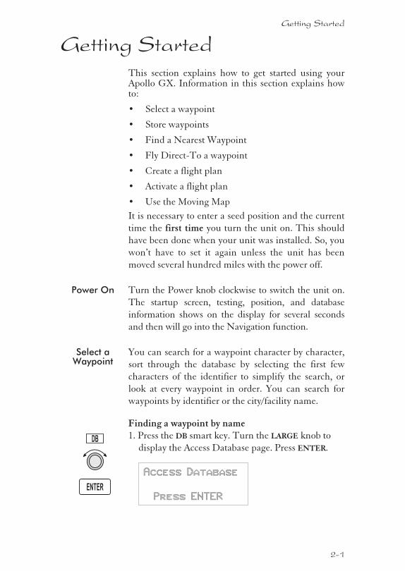
Finding a waypoint by name1. Press the DB smart key. Turn the LARGE knob to
display the Access Database page. Press ENTER.
Access Database
Press ENTER
Getting Started
2-1
DB
ENTER
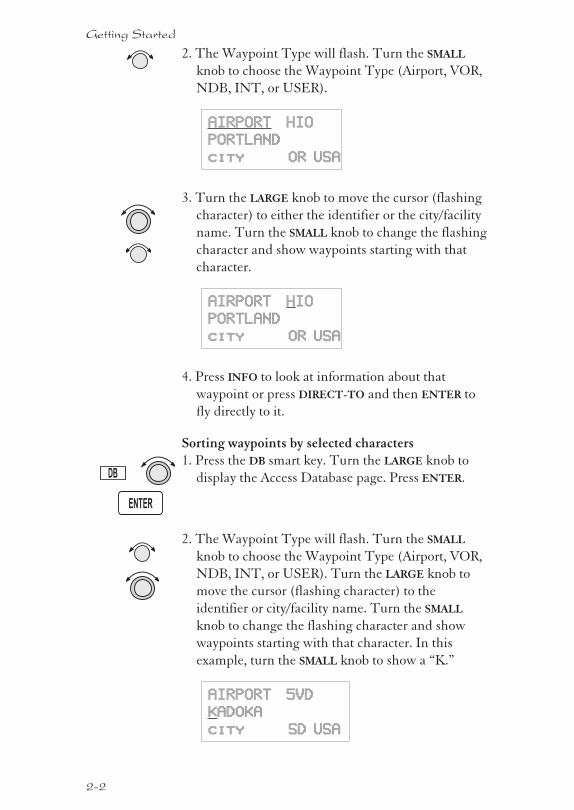
2. The Waypoint Type will flash. Turn the SMALL
knob to choose the Waypoint Type (Airport, VOR,
NDB, INT, or USER).
AIRPORT HIO
PORTLAND
city OR USA
3. Turn the LARGE knob to move the cursor (flashing
character) to either the identifier or the city/facility
name. Turn the SMALL knob to change the flashing
character and show waypoints starting with that
character.
AIRPORT HIO
PORTLAND
city OR USA
4. Press INFO to look at information about that
waypoint or press DIRECT-TO and then ENTER to
fly directly to it.
Sorting waypoints by selected characters1. Press the DB smart key. Turn the LARGE knob to
display the Access Database page. Press ENTER.
2. The Waypoint Type will flash. Turn the SMALL
knob to choose the Waypoint Type (Airport, VOR,
NDB, INT, or USER). Turn the LARGE knob to
move the cursor (flashing character) to the
identifier or city/facility name. Turn the SMALL
knob to change the flashing character and show
waypoints starting with that character. In this
example, turn the SMALL knob to show a “K.”
AIRPORT 5VD
KADOKA
city SD USA
2-2
Getting Started
DB
ENTER
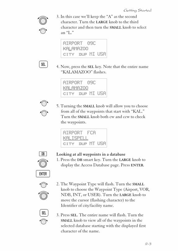
3. In this case we’ll keep the “A” as the second
character. Turn the LARGE knob to the third
character and then turn the SMALL knob to select
an “L.”
AIRPORT 09C
KALAMAZOO
city dup MI USA
4. Now, press the SEL key. Note that the entire name
“KALAMAZOO” flashes.
AIRPORT 09C
KALAMAZOO
city dup MI USA
5. Turning the SMALL knob will allow you to choose
from all of the waypoints that start with “KAL.”
Turn the SMALL knob both cw and ccw to check
the waypoints.
AIRPORT FCA
KALISPELL
city dup MT USA
Looking at all waypoints in a database1. Press the DB smart key. Turn the LARGE knob to
display the Access Database page. Press ENTER.
2. The Waypoint Type will flash. Turn the SMALL
knob to choose the Waypoint Type (Airport, VOR,
NDB, INT, or USER). Turn the LARGE knob to
move the cursor (flashing character) to the
Identifier of city/facility name.
3. Press SEL. The entire name will flash. Turn the
SMALL knob to view all of the waypoints in the
selected database starting with the displayed first
character of the name.
2-3
Getting Started
DB
ENTER
SEL
SEL
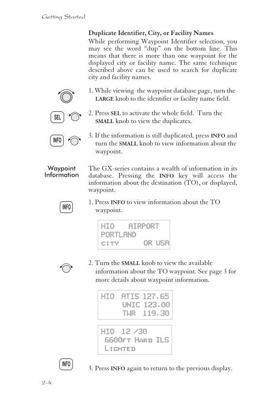
Duplicate Identifier, City, or Facility NamesWhile performing Waypoint Identifier selection, youmay see the word “dup” on the bottom line. Thismeans that there is more than one waypoint for thedisplayed city or facility name. The same techniquedescribed above can be used to search for duplicatecity and facility names.
1. While viewing the waypoint database page, turn theLARGE knob to the identifier or facility name field.
2. Press SEL to activate the whole field. Turn theSMALL knob to view the duplicates.
3. If the information is still duplicated, press INFO andturn the SMALL knob to view information about thewaypoint.
WaypointInformation
The GX-series contains a wealth of information in itsdatabase. Pressing the INFO key will access theinformation about the destination (TO), or displayed,waypoint.
1. Press INFO to view information about the TOwaypoint.
HIO AIRPORT
PORTLAND
city OR USA
2. Turn the SMALL knob to view the available
information about the TO waypoint. See page 3 for
more details about waypoint information.
HIO ATIS 127.65
UNIC 123.00
TWR 119.30
HIO 12 /30
6600ft Hard ILS
Lighted
3. Press INFO again to return to the previous display.
2-4
Getting Started
INFO
INFO
INFO
SEL
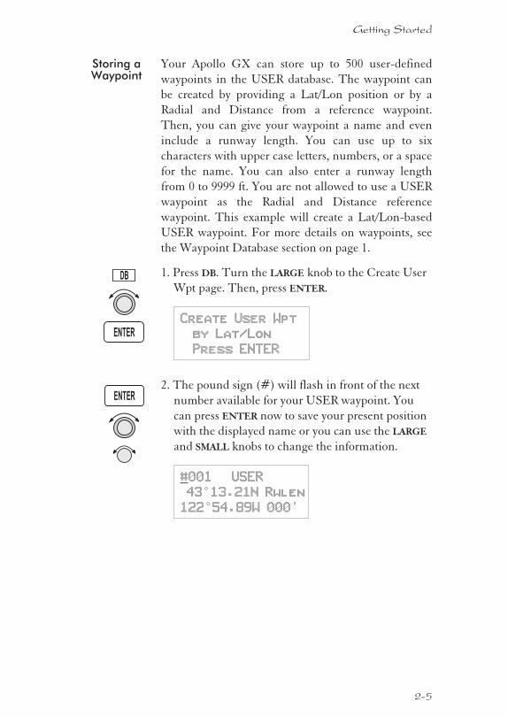
Storing aWaypoint
Your Apollo GX can store up to 500 user-defined
waypoints in the USER database. The waypoint can
be created by providing a Lat/Lon position or by a
Radial and Distance from a reference waypoint.
Then, you can give your waypoint a name and even
include a runway length. You can use up to six
characters with upper case letters, numbers, or a space
for the name. You can also enter a runway length
from 0 to 9999 ft. You are not allowed to use a USER
waypoint as the Radial and Distance reference
waypoint. This example will create a Lat/Lon-based
USER waypoint. For more details on waypoints, see
the Waypoint Database section on page 1.
1. Press DB. Turn the LARGE knob to the Create User
Wpt page. Then, press ENTER.
Create User Wpt
by Lat/Lon
Press ENTER
2. The pound sign (#) will flash in front of the next
number available for your USER waypoint. You
can press ENTER now to save your present position
with the displayed name or you can use the LARGE
and SMALL knobs to change the information.
#001 USER
43°13.21N Rwlen
122°54.89W 000’
2-5
Getting Started
ENTER
ENTER
DB
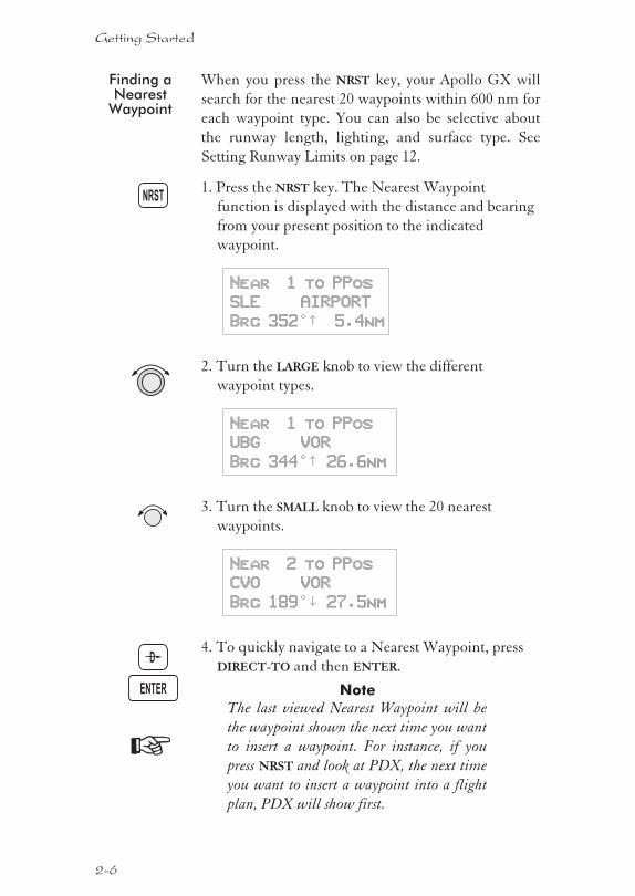
Finding aNearest
Waypoint
When you press the NRST key, your Apollo GX will
search for the nearest 20 waypoints within 600 nm for
each waypoint type. You can also be selective about
the runway length, lighting, and surface type. See
Setting Runway Limits on page 12.
1. Press the NRST key. The Nearest Waypoint
function is displayed with the distance and bearing
from your present position to the indicated
waypoint.
Near 1 to PPos
SLE AIRPORT
Brg 352°½ 5.4nm
2. Turn the LARGE knob to view the different
waypoint types.
Near 1 to PPos
UBG VOR
Brg 344°½ 26.6nm
3. Turn the SMALL knob to view the 20 nearest
waypoints.
Near 2 to PPos
CVO VOR
Brg 189°² 27.5nm
4. To quickly navigate to a Nearest Waypoint, press
DIRECT-TO and then ENTER.
Note
The last viewed Nearest Waypoint will be
the waypoint shown the next time you want
to insert a waypoint. For instance, if you
press NRST and look at PDX, the next time
you want to insert a waypoint into a flight
plan, PDX will show first.
2-6
Getting Started
NRST
ENTER
D
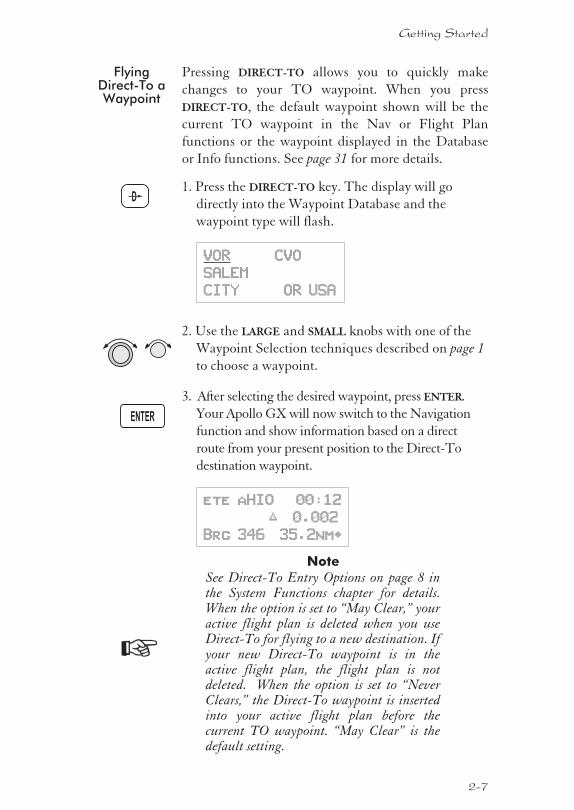
FlyingDirect-To aWaypoint
Pressing DIRECT-TO allows you to quickly make
changes to your TO waypoint. When you press
DIRECT-TO, the default waypoint shown will be the
current TO waypoint in the Nav or Flight Plan
functions or the waypoint displayed in the Database
or Info functions. See page 31 for more details.
1. Press the DIRECT-TO key. The display will go
directly into the Waypoint Database and the
waypoint type will flash.
VOR CVO
SALEM
CITY OR USA
2. Use the LARGE and SMALL knobs with one of the
Waypoint Selection techniques described on page 1
to choose a waypoint.
3. After selecting the desired waypoint, press ENTER.
Your Apollo GX will now switch to the Navigation
function and show information based on a direct
route from your present position to the Direct-To
destination waypoint.
ete aHIO 00:12
“ 0.002
Brg 346 35.2nm·
Note
See Direct-To Entry Options on page 8 inthe System Functions chapter for details.When the option is set to “May Clear,” youractive flight plan is deleted when you useDirect-To for flying to a new destination. Ifyour new Direct-To waypoint is in theactive flight plan, the flight plan is notdeleted. When the option is set to “NeverClears,” the Direct-To waypoint is insertedinto your active flight plan before thecurrent TO waypoint. “May Clear” is thedefault setting.
2-7
Getting Started
D
ENTER
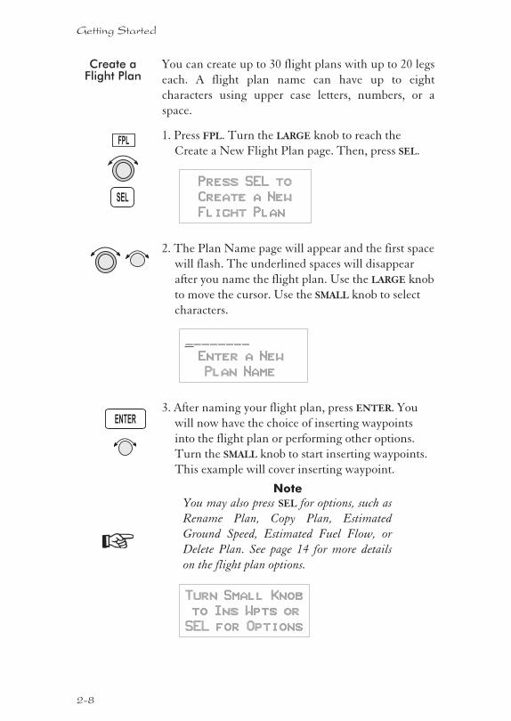
Create aFlight Plan
You can create up to 30 flight plans with up to 20 legs
each. A flight plan name can have up to eight
characters using upper case letters, numbers, or a
space.
1. Press FPL. Turn the LARGE knob to reach the
Create a New Flight Plan page. Then, press SEL.
Press SEL to
Create a New
Flight Plan
2. The Plan Name page will appear and the first space
will flash. The underlined spaces will disappear
after you name the flight plan. Use the LARGE knob
to move the cursor. Use the SMALL knob to select
characters.
________
Enter a New
Plan Name
3. After naming your flight plan, press ENTER. You
will now have the choice of inserting waypoints
into the flight plan or performing other options.
Turn the SMALL knob to start inserting waypoints.
This example will cover inserting waypoint.
Note
You may also press SEL for options, such as
Rename Plan, Copy Plan, Estimated
Ground Speed, Estimated Fuel Flow, or
Delete Plan. See page 14 for more details
on the flight plan options.
Turn Small Knob
to Ins Wpts or
SEL for Options
2-8
Getting Started
SEL
ENTER
FPL
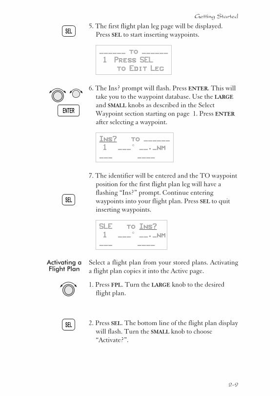
5. The first flight plan leg page will be displayed.
Press SEL to start inserting waypoints.
______ to ______
1 Press SEL
to Edit Leg
6. The Ins? prompt will flash. Press ENTER. This will
take you to the waypoint database. Use the LARGE
and SMALL knobs as described in the Select
Waypoint section starting on page 1. Press ENTER
after selecting a waypoint.
Ins? to ______
1 ___° __._nm
___ ____
7. The identifier will be entered and the TO waypoint
position for the first flight plan leg will have a
flashing “Ins?” prompt. Continue entering
waypoints into your flight plan. Press SEL to quit
inserting waypoints.
SLE to Ins?
1 ___° __._nm
___ ____
Activating aFlight Plan
Select a flight plan from your stored plans. Activating
a flight plan copies it into the Active page.
1. Press FPL. Turn the LARGE knob to the desired
flight plan.
2. Press SEL. The bottom line of the flight plan display
will flash. Turn the SMALL knob to choose
“Activate?”.
2-9
Getting Started
SEL
SEL
SEL
ENTER
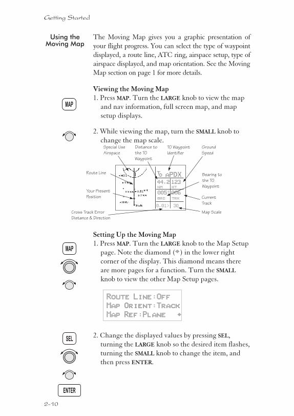
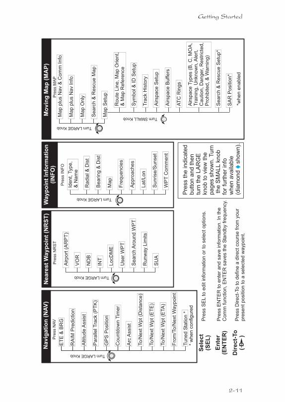
Using theMoving Map
The Moving Map gives you a graphic presentation of
your flight progress. You can select the type of waypoint
displayed, a route line, ATC ring, airspace setup, type of
airspace displayed, and map orientation. See the Moving
Map section on page 1 for more details.
Viewing the Moving Map1. Press MAP. Turn the LARGE knob to view the map
and nav information, full screen map, and map
setup displays.
2. While viewing the map, turn the SMALL knob to
change the map scale.
Setting Up the Moving Map1. Press MAP. Turn the LARGE knob to the Map Setup
page. Note the diamond (·) in the lower right
corner of the display. This diamond means there
are more pages for a function. Turn the SMALL
knob to view the other Map Setup pages.
Route Line:Off
Map Orient:Track
Map Ref:Plane ·
2. Change the displayed values by pressing SEL,
turning the LARGE knob so the desired item flashes,
turning the SMALL knob to change the item, and
then press ENTER.
2-10
Getting Started
MAP
ENTER
MAP
SEL
TO Waypoint
Identifier
Cross Track Error
Distance & Direction
Bearing to
the TO
Waypoint
Distance to
the TO
Waypoint
Ground
Speed
Current
Track
Map Scale
aPDX
44.2
005½
123
006brg trk
nm kt
0.01> 30
to
Route Line
Your Present
Position
Special Use
Airspace
2-11
Getting Started
Se
lec
t(S
EL
)
Dir
ec
t-To
(D
)
En
ter
(EN
TE
R)
Pre
ss
SE
Lto
ed
itin
form
atio
no
rto
se
lecto
ptio
ns.
Pre
ss
EN
TE
Rto
en
ter
an
dsa
ve
info
rma
tio
n.In
the
Co
mm
fun
ctio
n,E
NT
ER
save
sth
eS
tan
db
yfr
eq
ue
ncy.
Pre
ss
Dire
ct-
To
tod
efin
ea
dire
ctco
urs
efr
om
yo
ur
pre
se
ntp
ositio
nto
asele
cte
dw
ayp
oin
t.
Pre
ss
the
ind
ica
ted
bu
tto
na
nd
the
ntu
rnth
eL
AR
GE
kn
ob
tovie
wth
epa
ge
ssh
ow
n.T
urn
the
SM
AL
Lkn
ob
for
furt
he
rin
fow
he
na
va
ilab
le(d
iam
on
dsh
ow
n).
Ide
nt,
Typ
e,
&N
am
e
Ra
dia
l&
Dis
t
Be
arin
g&
Dis
t
Ma
p
Fre
qu
en
cie
s
Ap
pro
ach
es
La
t/L
on
Su
nrise
/Su
nse
t
WP
TC
om
me
nt
Pre
ss
INF
O
Wayp
oin
tIn
form
ati
on
(IN
FO
)
TurnLARGEKnob
ET
E&
BR
G
RA
IMP
red
ictio
n
Altitu
de
Assis
t
Pa
ralle
lT
rack
(PT
K)
GP
SP
ositio
n
Co
un
tdo
wn
Tim
er
Arc
Assis
t
To
/Ne
xtW
pt(D
ista
nce
)
To
/Ne
xtW
pt(E
TE
)
To
/Ne
xtW
pt(E
TA
)
Fro
m/T
o/N
extW
ayp
oin
t
Tu
ne
dS
tatio
n*
*w
he
nco
nfig
ure
d
Pre
ss
NA
V
Navig
ati
on
(NA
V)
TurnLARGEKnob
Airp
ort
(AR
PT
)
VO
R
ND
B
INT
Lo
cD
ME
Use
rW
PT
Se
arc
hA
rou
nd
WP
T
Ru
nw
ay
Lim
its
SU
A
Pre
ss
NR
ST
Neare
st
Wayp
oin
t(N
RS
T)
TurnLARGEKnob
Ma
pp
lus
Na
v&
Co
mm
Info
Ma
pp
lus
Na
vIn
fo
Ma
pO
nly
Se
arc
h&
Re
scu
eM
ap
Ma
pS
etu
p
Ro
ute
Lin
e,M
ap
Orie
nt,
&M
ap
Re
fere
nce
Sym
bo
l&
IDS
etu
p
Tra
ck
His
tory
Airspa
ce
Setu
p
Airspa
ce
Buffe
rs
AT
CR
ing
s
Airspa
ce
Typ
es
(B,C
,M
OA
,T
rain
ing
,U
nkn
ow
n,A
lert
,C
au
tio
n,D
an
ge
r,R
estr
icte
d,
Pro
hib
ite
d,&
Wa
rnin
g)
Se
arc
h&
Re
scu
eS
etu
p*
SA
RP
ositio
n*
TurnLARGEKnob
TurnSMALLKnob
Pre
ss
MA
P
Mo
vin
gM
ap
(MA
P)
*wh
en
en
ab
led
2-12
Getting Started
Tu
rnL
AR
GE
Kn
ob
toch
an
ge
MH
z
Tu
rnS
MA
LL
Kn
ob
toch
an
ge
kH
z
Pre
ss
<->
toto
gg
leA
ctive
&S
tan
db
y
Pre
ss
MO
Nto
mo
nito
rS
tan
db
y
Pre
ss
ME
Mto
me
mo
rize
Sta
nd
by
Pre
ss
RC
Lto
reca
llsto
red
fre
qu
en
cie
s
Pre
ss
CO
M
Tu
rnth
eL
AR
GE
Kn
ob
tovie
wfr
eq
ue
ncy
typ
es
Tu
rnth
eS
MA
LL
Kn
ob
tovie
wfr
eq
ue
ncie
sfo
rse
lecte
dty
pe
Co
mm
Rad
io(C
OM
)
Pre
ss
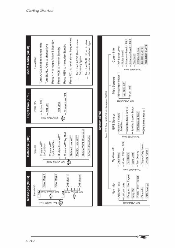
MS
G
Ne
w
Old
TurnLARGEKnob
TurnSMALLKnob
Ne
wM
sg
1. . . N
ew
Msg
nTurnSMALLKnob
Old
Msg
1. . . O
ldM
sg
n
Me
ss
ag
es
(MS
G)
Active
FP
L
FP
L#
1. . . F
PL
#3
0
Cre
ate
Ne
wF
PL
TurnLARGEKnob
Pre
ss
FP
L
Flig
ht
Pla
n(F
PL
)
Pre
ss
SY
S.T
urn
LA
RG
EK
no
b,th
en
pre
ss
EN
TE
R.
Nav
Info
Au
ton
av
Tim
e
La
t/L
on
Un
its
Pro
gra
mN
av
Pa
ge
s
Ma
gV
ar
Flig
htT
ime
rT
rig
ge
r
Dire
ct-
To
CD
IS
ca
ling
TurnLARGEKnob
Sy
ste
m(S
YS
)
Syste
mIn
fo
Da
te/T
ime
Te
stD
isp
lay
Dis
pla
yB
rig
htn
ess
Ow
ne
rN
am
e
Mo
de
l,S
WV
er,
S/N
Fu
elU
nits
Ba
roU
nits
TurnLARGEKnob
GP
SS
en
so
r
He
alth
y&
Vis
ible
Sa
telli
tes
Sa
telli
tes
Use
dfo
rF
ix
Sa
telli
teS
ea
rch
Sta
tus
GP
SD
ate
&T
ime
GP
SN
orm
alR
ese
t
TurnLARGEKnob
Mis
cS
en
so
rs
En
co
din
gA
ltim
ete
r
Air
Da
taIn
fo
Fu
elIn
fo
TurnLARGEKnob
Co
mm
Info
RF
Sig
na
lL
eve
l
No
ise
Le
ve
l
Inte
rco
mS
qu
elc
hM
ic1
Inte
rco
mS
qu
elc
hM
ic2
Tra
nsm
it
Inte
rco
mL
eve
l
Sid
eto
ne
Le
ve
l
He
adp
ho
ne
Le
ve
l
TurnLARGEKnob
Pre
ss
DB
Cre
ate
WP
Tb
yL
at/
Lo
n
Cre
ate
WP
Tb
yR
ad
ial/D
is
Up
da
teU
se
rW
PT
Cre
ate
WP
Tb
yG
rid
De
lete
Use
rW
PT
Mo
dify
Use
rW
PT
De
lete
WP
TC
om
men
t
Acce
ss
Da
tab
ase
TurnLARGEKnob
Da
tab
as
e(D
B)
Navigation BasicsThis section explores the navigation function and
describes the powerful features it contains.
About theNavigationFunction
The navigation function is always active. When you
use other functions, the navigation function continues
to run “in the background” calculating your present
position, navigating your programmed route (if
active), and alerting you to events or conditions
important to navigation. When you finish using other
functions and return to the navigation function, the
last navigation display used is shown.
About theNavigationFunctionDisplays
While you navigate, the Apollo GX gives you
information in the Navigation function displays. The
navigation information displays and sequencing rate
are user-programmable. See the Nav info section of
the System Functions chapter (see page 1) for your
options. The LARGE knob will select the higher level
Nav functions: Nav pages, Parallel Track Offset, GPS
Position, Countdown Timer, and the
FROM/TO/NEXT Waypoints. The SMALL knob will
look at the pages available for each function; a
diamond (·) will be shown on the lower, right side of
the display if more pages are available.
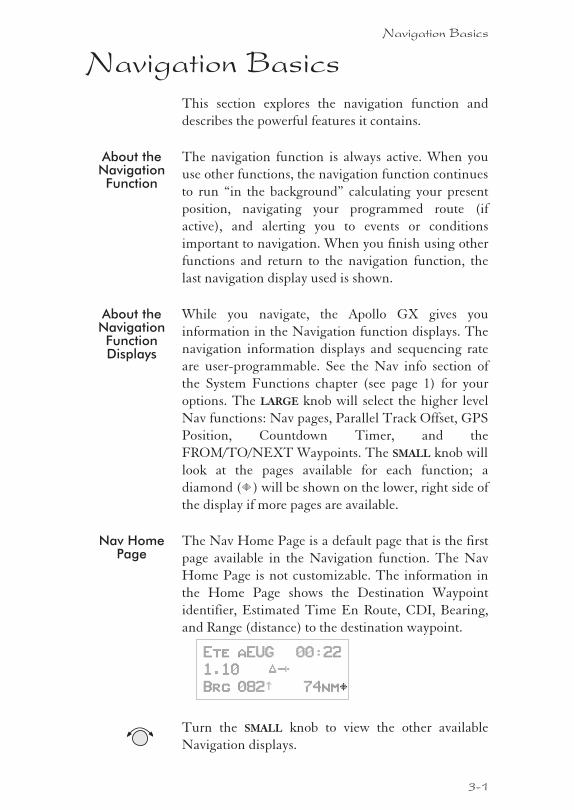
Nav HomePage
The Nav Home Page is a default page that is the first
page available in the Navigation function. The Nav
Home Page is not customizable. The information in
the Home Page shows the Destination Waypoint
identifier, Estimated Time En Route, CDI, Bearing,
and Range (distance) to the destination waypoint.
Ete aEUG 00:22
1.10 “¼¸
Brg 082½ 74nmY
Turn the SMALL knob to view the other available
Navigation displays.
Navigation Basics
3-1
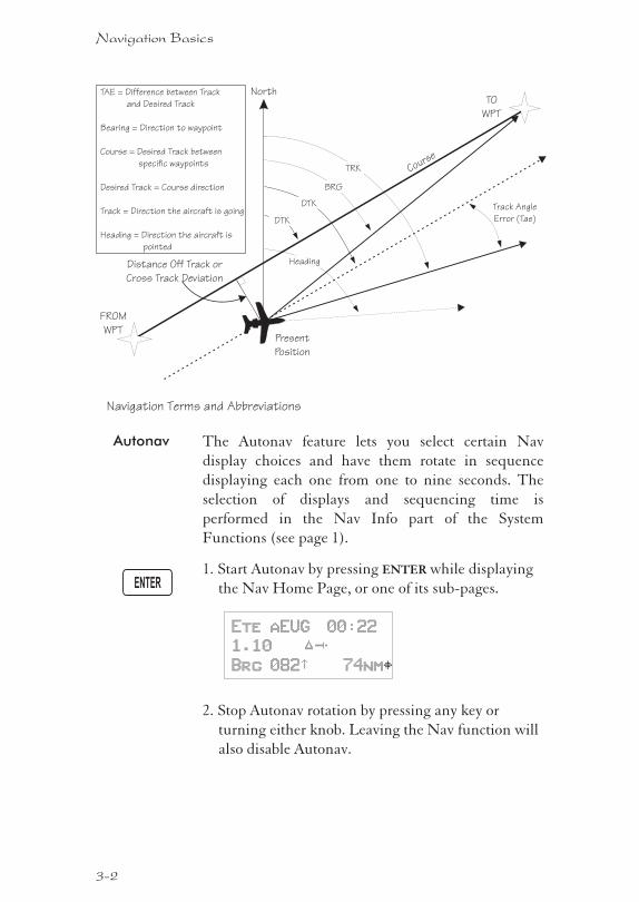
Autonav The Autonav feature lets you select certain Nav
display choices and have them rotate in sequence
displaying each one from one to nine seconds. The
selection of displays and sequencing time is
performed in the Nav Info part of the System
Functions (see page 1).
1. Start Autonav by pressing ENTER while displaying
the Nav Home Page, or one of its sub-pages.
Ete aEUG 00:22
1.10 “¼¸
Brg 082½ 74nmY
2. Stop Autonav rotation by pressing any key or
turning either knob. Leaving the Nav function will
also disable Autonav.
3-2
Navigation Basics
ENTER
TO
WPT
FROM
WPT
North
Track Angle
Error (Tae)
Present
Position
BRG
TRK
DTK
Distance Off Track or
Cross Track Deviation
DTK
TAE = Difference between Track
and Desired Track
Bearing = Direction to waypoint
Course = Desired Track between
specific waypoints
Desired Track = Course direction
Track = Direction the aircraft is going
Heading = Direction the aircraft is
pointed
Heading
Course
Navigation Terms and Abbreviations
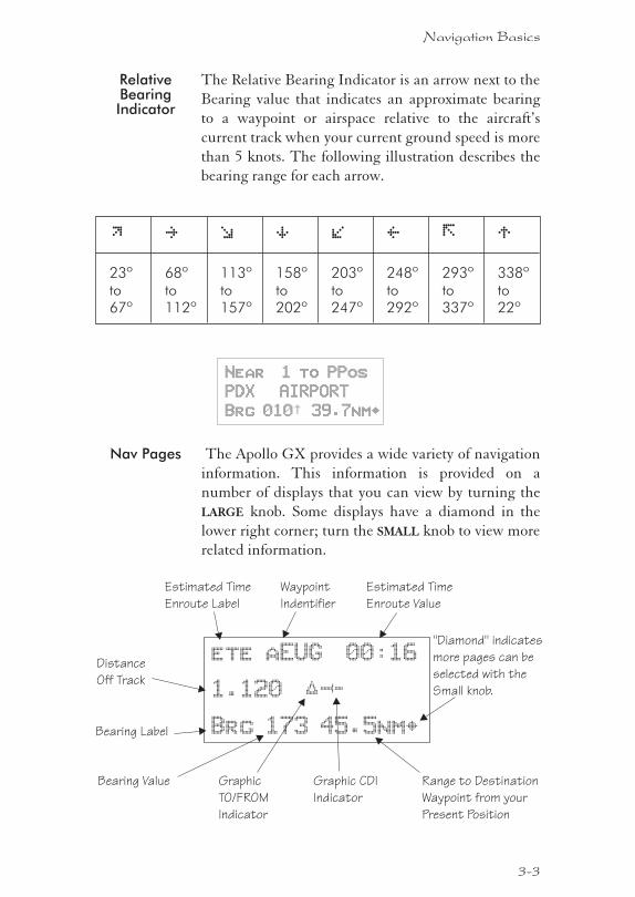
RelativeBearingIndicator
The Relative Bearing Indicator is an arrow next to the
Bearing value that indicates an approximate bearing
to a waypoint or airspace relative to the aircraft’s
current track when your current ground speed is more
than 5 knots. The following illustration describes the
bearing range for each arrow.
M N O P Q R \ T
23ºto67º
68ºto112º
113ºto157º
158ºto202º
203ºto247º
248ºto292º
293ºto337º
338ºto22º
Near 1 to PPos
PDX AIRPORT
Brg 010½ 39.7nm·
Nav Pages The Apollo GX provides a wide variety of navigation
information. This information is provided on a
number of displays that you can view by turning the
LARGE knob. Some displays have a diamond in the
lower right corner; turn the SMALL knob to view more
related information.
3-3
Navigation Basics
Estimated Time
Enroute Label
Waypoint
Indentifier
Bearing Value
Estimated Time
Enroute Value
Bearing Label
Range to Destination
Waypoint from your
Present Position
"Diamond" indicates
more pages can be
selected with the
Small knob.
ete aEUG 00:16
1.120
Brg 173 45.5nm
“¼º
·
Graphic CDI
Indicator
Distance
Off Track
Graphic
TO/FROM
Indicator
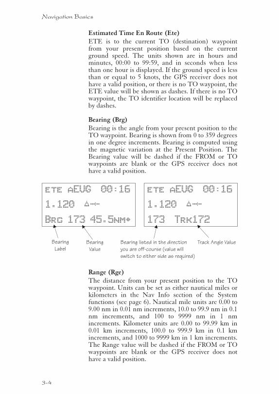
Estimated Time En Route (Ete)ETE is to the current TO (destination) waypointfrom your present position based on the currentground speed. The units shown are in hours andminutes, 00:00 to 99:59, and in seconds when lessthan one hour is displayed. If the ground speed is lessthan or equal to 5 knots, the GPS receiver does nothave a valid position, or there is no TO waypoint, theETE value will be shown as dashes. If there is no TOwaypoint, the TO identifier location will be replacedby dashes.
Bearing (Brg)Bearing is the angle from your present position to theTO waypoint. Bearing is shown from 0 to 359 degreesin one degree increments. Bearing is computed usingthe magnetic variation at the Present Position. TheBearing value will be dashed if the FROM or TOwaypoints are blank or the GPS receiver does nothave a valid position.
Range (Rge)The distance from your present position to the TOwaypoint. Units can be set as either nautical miles orkilometers in the Nav Info section of the Systemfunctions (see page 6). Nautical mile units are 0.00 to9.00 nm in 0.01 nm increments, 10.0 to 99.9 nm in 0.1nm increments, and 100 to 9999 nm in 1 nmincrements. Kilometer units are 0.00 to 99.99 km in0.01 km increments, 100.0 to 999.9 km in 0.1 kmincrements, and 1000 to 9999 km in 1 km increments.The Range value will be dashed if the FROM or TOwaypoints are blank or the GPS receiver does nothave a valid position.
3-4
Navigation Basics
Bearing
Value
Bearing
Label
ete aEUG 00:16
1.120
Brg 173 45.5nm
“¼º
·
Bearing listed in the direction
you are off-course (value will
switch to either side as required)
ete aEUG 00:16
1.120
173 Trk172
“¼º
Track Angle Value
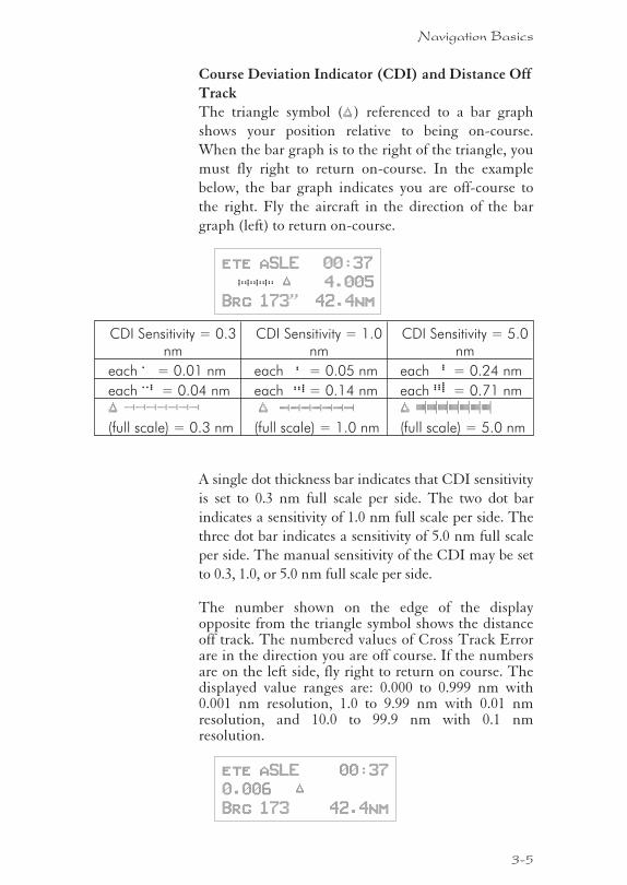
Course Deviation Indicator (CDI) and Distance Off
TrackThe triangle symbol (“) referenced to a bar graph
shows your position relative to being on-course.
When the bar graph is to the right of the triangle, you
must fly right to return on-course. In the example
below, the bar graph indicates you are off-course to
the right. Fly the aircraft in the direction of the bar
graph (left) to return on-course.
ete aSLE 00:37
#### “ 4.005
Brg 173¯ 42.4nm
CDI Sensitivity = 0.3nm
CDI Sensitivity = 1.0nm
CDI Sensitivity = 5.0nm
each 7 = 0.01 nm each $ = 0.05 nm each H = 0.24 nm
each 6 = 0.04 nm each z = 0.14 nm each B = 0.71 nm
“ ›››››››(full scale) = 0.3 nm
“ ¼¼¼¼¼¼¼(full scale) = 1.0 nm
“ ¥¥¥¥¥¥¥(full scale) = 5.0 nm
A single dot thickness bar indicates that CDI sensitivity
is set to 0.3 nm full scale per side. The two dot bar
indicates a sensitivity of 1.0 nm full scale per side. The
three dot bar indicates a sensitivity of 5.0 nm full scale
per side. The manual sensitivity of the CDI may be set
to 0.3, 1.0, or 5.0 nm full scale per side.
The number shown on the edge of the displayopposite from the triangle symbol shows the distanceoff track. The numbered values of Cross Track Errorare in the direction you are off course. If the numbersare on the left side, fly right to return on course. Thedisplayed value ranges are: 0.000 to 0.999 nm with0.001 nm resolution, 1.0 to 9.99 nm with 0.01 nmresolution, and 10.0 to 99.9 nm with 0.1 nmresolution.
ete aSLE 00:37
0.006 “
Brg 173 42.4nm
3-5
Navigation Basics
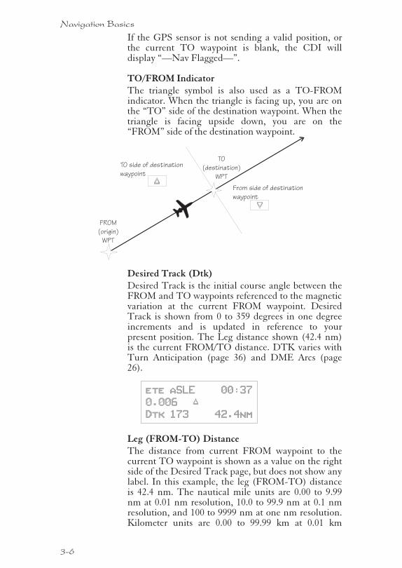
If the GPS sensor is not sending a valid position, orthe current TO waypoint is blank, the CDI willdisplay “—Nav Flagged—”.
TO/FROM IndicatorThe triangle symbol is also used as a TO-FROMindicator. When the triangle is facing up, you are onthe “TO” side of the destination waypoint. When thetriangle is facing upside down, you are on the“FROM” side of the destination waypoint.
Desired Track (Dtk)Desired Track is the initial course angle between theFROM and TO waypoints referenced to the magneticvariation at the current FROM waypoint. DesiredTrack is shown from 0 to 359 degrees in one degreeincrements and is updated in reference to yourpresent position. The Leg distance shown (42.4 nm)is the current FROM/TO distance. DTK varies withTurn Anticipation (page 36) and DME Arcs (page26).
ete aSLE 00:37
0.006 “
Dtk 173 42.4nm
Leg (FROM-TO) DistanceThe distance from current FROM waypoint to thecurrent TO waypoint is shown as a value on the rightside of the Desired Track page, but does not show anylabel. In this example, the leg (FROM-TO) distanceis 42.4 nm. The nautical mile units are 0.00 to 9.99nm at 0.01 nm resolution, 10.0 to 99.9 nm at 0.1 nmresolution, and 100 to 9999 nm at one nm resolution.Kilometer units are 0.00 to 99.99 km at 0.01 km
3-6
Navigation Basics
TO
(destination)
WPT
FROM
(origin)
WPT
TO side of destination
waypoint
From side of destination
waypoint
“
”
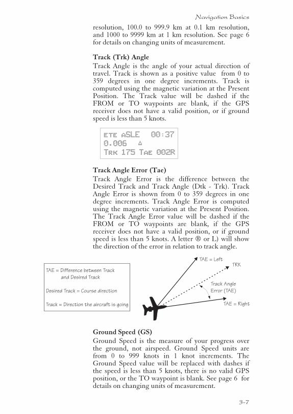
resolution, 100.0 to 999.9 km at 0.1 km resolution,and 1000 to 9999 km at 1 km resolution. See page 6for details on changing units of measurement.
Track (Trk) AngleTrack Angle is the angle of your actual direction oftravel. Track is shown as a positive value from 0 to359 degrees in one degree increments. Track iscomputed using the magnetic variation at the PresentPosition. The Track value will be dashed if theFROM or TO waypoints are blank, if the GPSreceiver does not have a valid position, or if groundspeed is less than 5 knots.
ete aSLE 00:37
0.006 “
Trk 175 Tae 002R
Track Angle Error (Tae)Track Angle Error is the difference between theDesired Track and Track Angle (Dtk - Trk). TrackAngle Error is shown from 0 to 359 degrees in onedegree increments. Track Angle Error is computedusing the magnetic variation at the Present Position.The Track Angle Error value will be dashed if theFROM or TO waypoints are blank, if the GPSreceiver does not have a valid position, or if groundspeed is less than 5 knots. A letter ® or L) will showthe direction of the error in relation to track angle.
Ground Speed (GS)Ground Speed is the measure of your progress overthe ground, not airspeed. Ground Speed units arefrom 0 to 999 knots in 1 knot increments. TheGround Speed value will be replaced with dashes ifthe speed is less than 5 knots, there is no valid GPSposition, or the TO waypoint is blank. See page 6 fordetails on changing units of measurement.
3-7
Navigation Basics
Track Angle
Error (TAE)
TRKTAE = Difference between Track
and Desired Track
Desired Track = Course direction
Track = Direction the aircraft is going
TAE = Left
TAE = Right
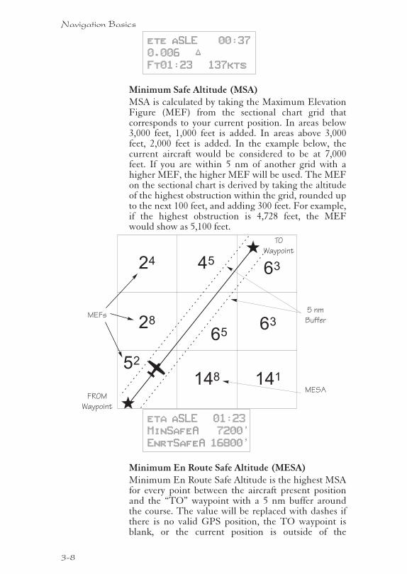
ete aSLE 00:37
0.006 “
Ft01:23 137kts
Minimum Safe Altitude (MSA)MSA is calculated by taking the Maximum ElevationFigure (MEF) from the sectional chart grid thatcorresponds to your current position. In areas below3,000 feet, 1,000 feet is added. In areas above 3,000feet, 2,000 feet is added. In the example below, thecurrent aircraft would be considered to be at 7,000feet. If you are within 5 nm of another grid with ahigher MEF, the higher MEF will be used. The MEFon the sectional chart is derived by taking the altitudeof the highest obstruction within the grid, rounded upto the next 100 feet, and adding 300 feet. For example,if the highest obstruction is 4,728 feet, the MEFwould show as 5,100 feet.
eta aSLE 01:23
MinSafeA 7200’
EnrtSafeA 16800’
Minimum En Route Safe Altitude (MESA)Minimum En Route Safe Altitude is the highest MSAfor every point between the aircraft present positionand the “TO” waypoint with a 5 nm buffer aroundthe course. The value will be replaced with dashes ifthere is no valid GPS position, the TO waypoint isblank, or the current position is outside of the
3-8
Navigation Basics
6528
14852
63
141
452463
FROM
Waypoint
TO
Waypoint
5 nm
BufferMEFs
MESA
database coverage area. In the example shown above,the MESA for the present position of the aircraftwould be 16,800 ft. The mountainous terrain wouldadd a 2,000 ft. buffer to the 14,800 ft. MaximumElevation figure indicated from the sectional chart.
Flight TimeFlight Time shows the elapsed time in hours and
minutes (00:00 to 99:59) from departure. If the Flight
Timer is not started the value will be replaced with
dashes. The Flight Timer Trigger options are set in
the System Functions (see page 8).
FT00:07
Time UTCTime is displayed using the 24 hour clock based onUniversal Coordinated Time. Units are hours andminutes (00:00 to 23:59).
13:15 UTC
Estimated Time of Arrival (ETA)The ETA is the arrival time at the current TOwaypoint at the current Ground Speed from thepresent position. The TO waypoint is displayed.Units are hours and minutes (00:00 to 23:59) basedon the UTC 24 hour clock. The values will bereplaced with dashes if the speed is less than 5 knots,there is no valid GPS position, or the TO and/ordestination waypoints are blank.
eta aEUG 09:11
NearestWaypoint &
AirspaceSearch
An important safety feature of the GX is its ability tolocate waypoints and airspaces closest to yourposition. Should you have to land quickly, you canuse this feature to locate a nearby waypoint, assign itas a destination, and quickly navigate to it. You canalso insert waypoints into an active flight plan.Besides the nearest waypoints to your presentposition, as an aid in flight planning, you can alsoselect a reference waypoint from the database andsearch for waypoints near to it. You can set up theNearest Waypoint Search function to filter for certain
3-9
Navigation Basics
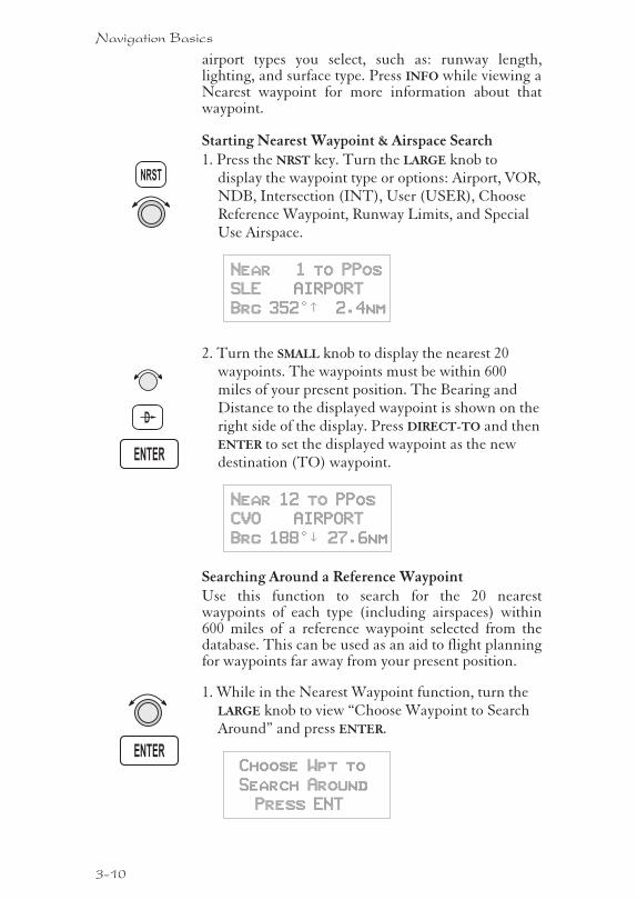
airport types you select, such as: runway length,lighting, and surface type. Press INFO while viewing aNearest waypoint for more information about thatwaypoint.
Starting Nearest Waypoint & Airspace Search1. Press the NRST key. Turn the LARGE knob to
display the waypoint type or options: Airport, VOR,NDB, Intersection (INT), User (USER), ChooseReference Waypoint, Runway Limits, and SpecialUse Airspace.
Near 1 to PPos
SLE AIRPORT
Brg 352°½ 2.4nm
2. Turn the SMALL knob to display the nearest 20waypoints. The waypoints must be within 600miles of your present position. The Bearing andDistance to the displayed waypoint is shown on theright side of the display. Press DIRECT-TO and thenENTER to set the displayed waypoint as the newdestination (TO) waypoint.
Near 12 to PPos
CVO AIRPORT
Brg 188°² 27.6nm
Searching Around a Reference WaypointUse this function to search for the 20 nearestwaypoints of each type (including airspaces) within600 miles of a reference waypoint selected from thedatabase. This can be used as an aid to flight planningfor waypoints far away from your present position.
1. While in the Nearest Waypoint function, turn theLARGE knob to view “Choose Waypoint to SearchAround” and press ENTER.
Choose Wpt to
Search Around
Press ENT
3-10
Navigation Basics
ENTER
D
NRST
ENTER
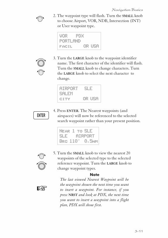
2. The waypoint type will flash. Turn the SMALL knob
to choose Airport, VOR, NDB, Intersection (INT)
or User waypoint type.
VOR PDX
PORTLAND
facil OR USA
3. Turn the LARGE knob to the waypoint identifier
name. The first character of the identifier will flash.
Turn the SMALL knob to change characters. Turn
the LARGE knob to select the next character to
change.
AIRPORT SLE
SALEM
city OR USA
4. Press ENTER. The Nearest waypoints (and
airspaces) will now be referenced to the selected
search waypoint rather than your present position.
Near 1 to SLE
SLE AIRPORT
Brg 110° 0.5nm
5. Turn the SMALL knob to view the nearest 20
waypoints of the selected type to the selected
reference waypoint. Turn the LARGE knob to
change waypoint types.
Note
The last viewed Nearest Waypoint will be
the waypoint shown the next time you want
to insert a waypoint. For instance, if you
press NRST and look at PDX, the next time
you want to insert a waypoint into a flight
plan, PDX will show first.
3-11
Navigation Basics
ENTER
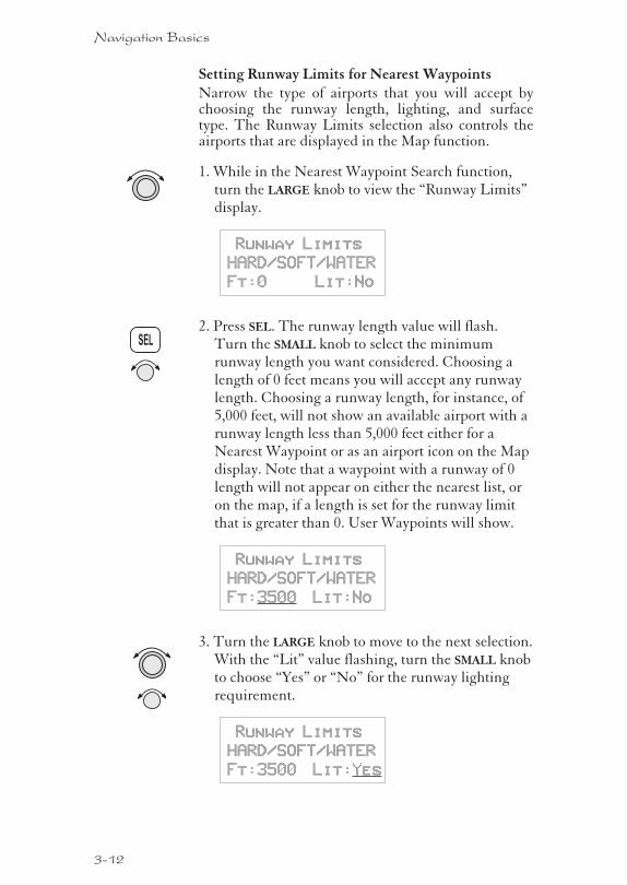
Setting Runway Limits for Nearest WaypointsNarrow the type of airports that you will accept bychoosing the runway length, lighting, and surfacetype. The Runway Limits selection also controls theairports that are displayed in the Map function.
1. While in the Nearest Waypoint Search function,turn the LARGE knob to view the “Runway Limits”display.
Runway Limits
HARD/SOFT/WATER
Ft:0 Lit:No
2. Press SEL. The runway length value will flash.Turn the SMALL knob to select the minimumrunway length you want considered. Choosing alength of 0 feet means you will accept any runwaylength. Choosing a runway length, for instance, of5,000 feet, will not show an available airport with arunway length less than 5,000 feet either for aNearest Waypoint or as an airport icon on the Mapdisplay. Note that a waypoint with a runway of 0length will not appear on either the nearest list, oron the map, if a length is set for the runway limitthat is greater than 0. User Waypoints will show.
Runway Limits
HARD/SOFT/WATER
Ft:3500 Lit:No
3. Turn the LARGE knob to move to the next selection.With the “Lit” value flashing, turn the SMALL knobto choose “Yes” or “No” for the runway lightingrequirement.
Runway Limits
HARD/SOFT/WATER
Ft:3500 Lit:Yes
3-12
Navigation Basics
SEL
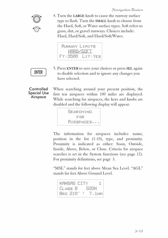
4. Turn the LARGE knob to cause the runway surface
type to flash. Turn the SMALL knob to choose from
the Hard, Soft, or Water surface types. Soft refers to
grass, dirt, or gravel runways. Choices include:
Hard, Hard/Soft, and Hard/Soft/Water.
Runway Limits
HARD/SOFT
Ft:3500 Lit:Yes
5. Press ENTER to save your choices or press SEL again
to disable selection and to ignore any changes you
have selected.
ControlledSpecial Use
Airspace
When searching around your present position, the
first ten airspaces within 100 miles are displayed.
While searching for airspaces, the keys and knobs are
disabled and the following display will appear.
Searching
for
Airspaces...
The information for airspaces includes: name,
position in the list (1-10), type, and proximity.
Proximity is indicated as either: Soon, Outside,
Inside, Above, Below, or Close. Criteria for airspace
searches is set in the System functions (see page 12).
For proximity definitions, see page 3.
“MSL” stands for feet above Mean Sea Level. “AGL”
stands for feet Above Ground Level.
KANSAS CITY 1
Class B SOON
Brg 210° ½ 7.1nm
3-13
Navigation Basics
ENTER
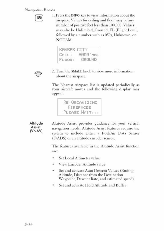
1. Press the INFO key to view information about the
airspace. Values for ceiling and floor may be any
number of positive feet less than 100,000. Values
may also be Unlimited, Ground, FL (Flight Level,
followed by a number such as 050), Unknown, or
NOTAM.
KANSAS CITY
Ceil: 8000’msl
Floor: GROUND
2. Turn the SMALL knob to view more information
about the airspace.
The Nearest Airspace list is updated periodically asyour aircraft moves and the following display mayappear.
Re-Organizing
Airspaces
Please Wait...
AltitudeAssist(VNAV)
Altitude Assist provides guidance for your vertical
navigation needs. Altitude Assist features require the
system to include either a Fuel/Air Data Sensor
(F/ADS) or an altitude encoder sensor.
The features available in the Altitude Assist function
are:
� Set Local Altimeter value
� View Encoder Altitude value
� Set and activate Auto Descent Values (EndingAltitude, Distance from the DestinationWaypoint, Descent Rate, and estimated speed)
� Set and activate Hold Altitude and Buffer
3-14
Navigation Basics
INFO
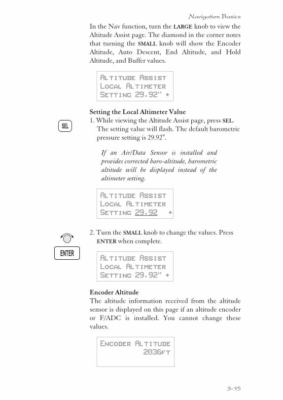
In the Nav function, turn the LARGE knob to view the
Altitude Assist page. The diamond in the corner notes
that turning the SMALL knob will show the Encoder
Altitude, Auto Descent, End Altitude, and Hold
Altitude, and Buffer values.
Altitude Assist
Local Altimeter
Setting 29.92" ·
Setting the Local Altimeter Value1. While viewing the Altitude Assist page, press SEL.
The setting value will flash. The default barometric
pressure setting is 29.92".
If an Air/Data Sensor is installed and
provides corrected baro-altitude, barometric
altitude will be displayed instead of the
altimeter setting.
Altitude Assist
Local Altimeter
Setting 29.92 ·
2. Turn the SMALL knob to change the values. Press
ENTER when complete.
Altitude Assist
Local Altimeter
Setting 29.92" ·
Encoder AltitudeThe altitude information received from the altitude
sensor is displayed on this page if an altitude encoder
or F/ADC is installed. You cannot change these
values.
Encoder Altitude
2036ft
3-15
Navigation Basics
SEL
ENTER
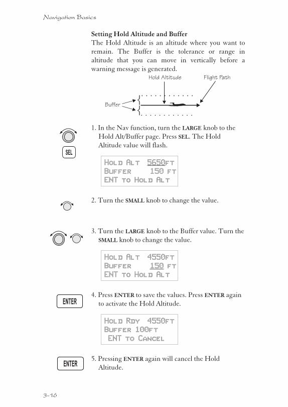
Setting Hold Altitude and BufferThe Hold Altitude is an altitude where you want to
remain. The Buffer is the tolerance or range in
altitude that you can move in vertically before a
warning message is generated.
1. In the Nav function, turn the LARGE knob to the
Hold Alt/Buffer page. Press SEL. The Hold
Altitude value will flash.
Hold Alt 5650ft
Buffer 150 ft
ENT to Hold Alt
2. Turn the SMALL knob to change the value.
3. Turn the LARGE knob to the Buffer value. Turn the
SMALL knob to change the value.
Hold Alt 4550ft
Buffer 150 ft
ENT to Hold Alt
4. Press ENTER to save the values. Press ENTER again
to activate the Hold Altitude.
Hold Rdy 4550ft
Buffer 100ft
ENT to Cancel
5. Pressing ENTER again will cancel the Hold
Altitude.
3-16
Navigation Basics
SEL
ENTER
ENTER
Hold Altitude
Buffer
Flight Path
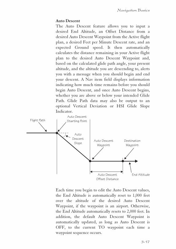
Auto DescentThe Auto Descent feature allows you to input a
desired End Altitude, an Offset Distance from a
desired Auto Descent Waypoint from the Active flight
plan, a desired Feet per Minute Descent rate, and an
expected Ground speed. It then automatically
calculates the distance remaining in your Active flight
plan to the desired Auto Descent Waypoint and,
based on the calculated glide path angle, your present
altitude, and the altitude you are descending to, alerts
you with a message when you should begin and end
your descent. A Nav item field displays information
indicating how much time remains before you should
begin Auto Descent, and once Auto Descent begins,
whether you are above or below your intended Glide
Path. Glide Path data may also be output to an
optional Vertical Deviation or HSI Glide Slope
Indicator.
Each time you begin to edit the Auto Descent values,
the End Altitude is automatically reset to 1,000 feet
over the altitude of the desired Auto Descent
Waypoint, if the waypoint is an airport. Otherwise,
the End Altitude automatically resets to 2,000 feet. In
addition, the default Auto Descent Waypoint is
automatically updated, as long as Auto Descent is
OFF, to the current TO waypoint each time a
waypoint sequence occurs.
3-17
Navigation Basics
Auto
Descent
Slope
Auto Descent
Offset Distance
Flight Path
End Altitude
Auto Descent
Starting Point
Auto Descent
Waypoint
Destination
Waypoint
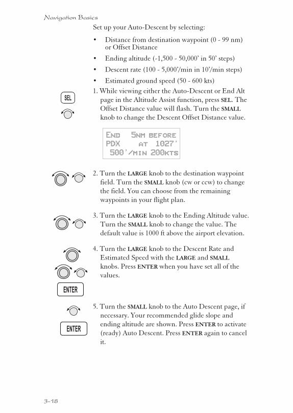
Set up your Auto-Descent by selecting:
� Distance from destination waypoint (0 - 99 nm)or Offset Distance
� Ending altitude (-1,500 - 50,000’ in 50’ steps)
� Descent rate (100 - 5,000’/min in 10’/min steps)
� Estimated ground speed (50 - 600 kts)
1. While viewing either the Auto-Descent or End Alt
page in the Altitude Assist function, press SEL. The
Offset Distance value will flash. Turn the SMALL
knob to change the Descent Offset Distance value.
End 5nm before
PDX at 1027’
500’/min 200kts
2. Turn the LARGE knob to the destination waypoint
field. Turn the SMALL knob (cw or ccw) to change
the field. You can choose from the remaining
waypoints in your flight plan.
3. Turn the LARGE knob to the Ending Altitude value.
Turn the SMALL knob to change the value. The
default value is 1000 ft above the airport elevation.
4. Turn the LARGE knob to the Descent Rate and
Estimated Speed with the LARGE and SMALL
knobs. Press ENTER when you have set all of the
values.
5. Turn the SMALL knob to the Auto Descent page, if
necessary. Your recommended glide slope and
ending altitude are shown. Press ENTER to activate
(ready) Auto Descent. Press ENTER again to cancel
it.
3-18
Navigation Basics
SEL
ENTER
ENTER
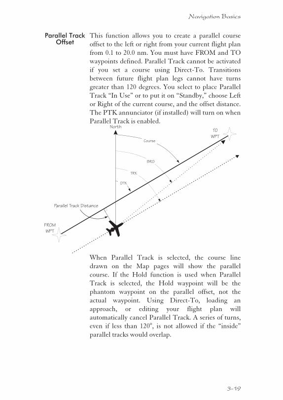
Parallel TrackOffset
This function allows you to create a parallel course
offset to the left or right from your current flight plan
from 0.1 to 20.0 nm. You must have FROM and TO
waypoints defined. Parallel Track cannot be activated
if you set a course using Direct-To. Transitions
between future flight plan legs cannot have turns
greater than 120 degrees. You select to place Parallel
Track “In Use” or to put it on “Standby,” choose Left
or Right of the current course, and the offset distance.
The PTK annunciator (if installed) will turn on when
Parallel Track is enabled.
When Parallel Track is selected, the course line
drawn on the Map pages will show the parallel
course. If the Hold function is used when Parallel
Track is selected, the Hold waypoint will be the
phantom waypoint on the parallel offset, not the
actual waypoint. Using Direct-To, loading an
approach, or editing your flight plan will
automatically cancel Parallel Track. A series of turns,
even if less than 120°, is not allowed if the “inside”
parallel tracks would overlap.
3-19
Navigation Basics
TO
WPT
FROM
WPT
North
BRG
Parallel Track Distance
Course
DTK
TRK
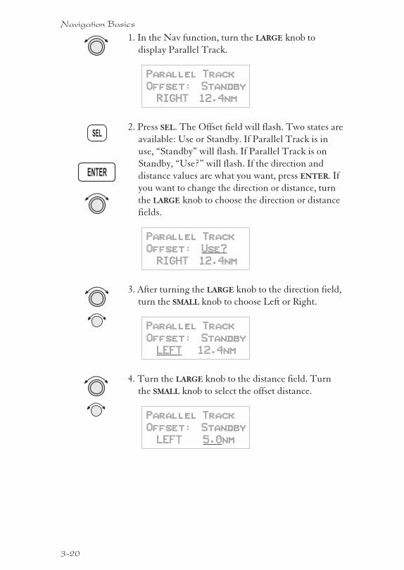
1. In the Nav function, turn the LARGE knob to
display Parallel Track.
Parallel Track
Offset: Standby
RIGHT 12.4nm
2. Press SEL. The Offset field will flash. Two states are
available: Use or Standby. If Parallel Track is in
use, “Standby” will flash. If Parallel Track is on
Standby, “Use?” will flash. If the direction and
distance values are what you want, press ENTER. If
you want to change the direction or distance, turn
the LARGE knob to choose the direction or distance
fields.
Parallel Track
Offset: Use?
RIGHT 12.4nm
3. After turning the LARGE knob to the direction field,
turn the SMALL knob to choose Left or Right.
Parallel Track
Offset: Standby
LEFT 12.4nm
4. Turn the LARGE knob to the distance field. Turn
the SMALL knob to select the offset distance.
Parallel Track
Offset: Standby
LEFT 5.0nm
3-20
Navigation Basics
SEL
ENTER
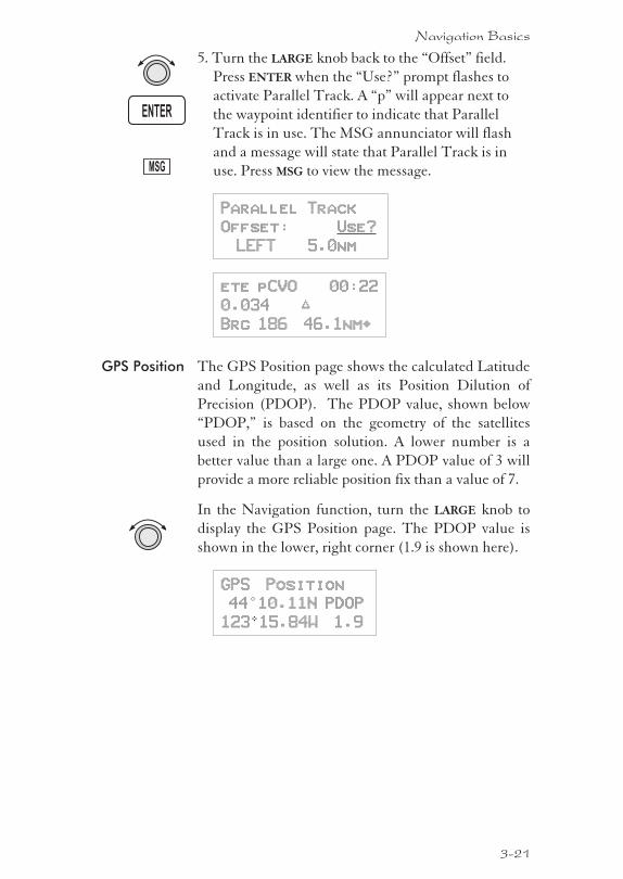
5. Turn the LARGE knob back to the “Offset” field.
Press ENTER when the “Use?” prompt flashes to
activate Parallel Track. A “p” will appear next to
the waypoint identifier to indicate that Parallel
Track is in use. The MSG annunciator will flash
and a message will state that Parallel Track is in
use. Press MSG to view the message.
Parallel Track
Offset: Use?
LEFT 5.0nm
ete pCVO 00:22
0.034 “
Brg 186 46.1nm·
GPS Position The GPS Position page shows the calculated Latitude
and Longitude, as well as its Position Dilution of
Precision (PDOP). The PDOP value, shown below
“PDOP,” is based on the geometry of the satellites
used in the position solution. A lower number is a
better value than a large one. A PDOP value of 3 will
provide a more reliable position fix than a value of 7.
In the Navigation function, turn the LARGE knob to
display the GPS Position page. The PDOP value is
shown in the lower, right corner (1.9 is shown here).
GPS Position
44°10.11N PDOP
123015.84W 1.9
3-21
Navigation Basics
MSG
ENTER
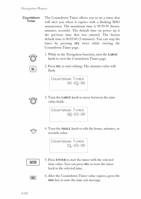
CountdownTimer
The Countdown Timer allows you to set a timer that
will alert you when it expires with a flashing MSG
annunciator. The maximum time is 99:59:59 (hours,
minutes, seconds). The default time on power up is
the previous time that was entered. The factory
default time is 00:03:00 (3 minutes). You can stop the
timer by pressing SEL twice while viewing the
Countdown Timer page.
1. While in the Navigation function, turn the LARGE
knob to view the Countdown Timer page.
2. Press SEL to start editing. The minutes value will
flash.
Countdown Timer
00:03:00
3. Turn the LARGE knob to move between the time
value fields.
Countdown Timer
00:03:00
4. Turn the SMALL knob to edit the hours, minutes, or
seconds value.
Countdown Timer
01:03:00
5. Press ENTER to start the timer with the selected
time value. You can press SEL to reset the timer
back to the selected time.
6. After the Countdown Timer value expires, press the
MSG key to note the time out message.
3-22
Navigation Basics
SEL
ENTER
MSG
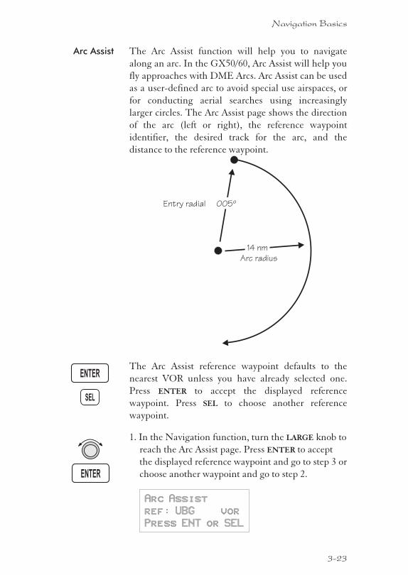
Arc Assist The Arc Assist function will help you to navigate
along an arc. In the GX50/60, Arc Assist will help you
fly approaches with DME Arcs. Arc Assist can be used
as a user-defined arc to avoid special use airspaces, or
for conducting aerial searches using increasingly
larger circles. The Arc Assist page shows the direction
of the arc (left or right), the reference waypoint
identifier, the desired track for the arc, and the
distance to the reference waypoint.
The Arc Assist reference waypoint defaults to the
nearest VOR unless you have already selected one.
Press ENTER to accept the displayed reference
waypoint. Press SEL to choose another reference
waypoint.
1. In the Navigation function, turn the LARGE knob to
reach the Arc Assist page. Press ENTER to accept
the displayed reference waypoint and go to step 3 or
choose another waypoint and go to step 2.
Arc Assist
ref: UBG vor
Press ENT or SEL
3-23
Navigation Basics
SEL
ENTER
ENTER
005º
14 nm
Entry radial
Arc radius
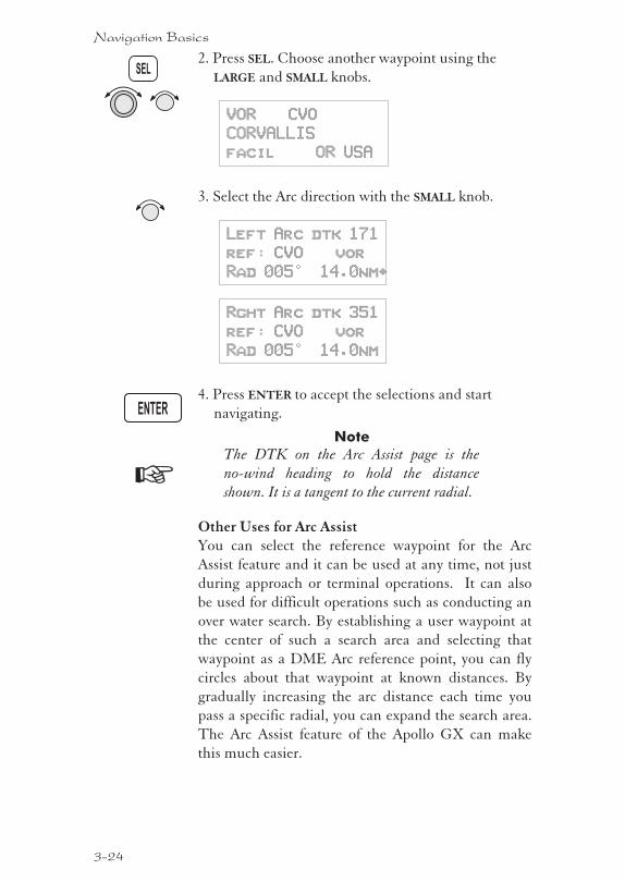
2. Press SEL. Choose another waypoint using the
LARGE and SMALL knobs.
VOR CVO
CORVALLIS
facil OR USA
3. Select the Arc direction with the SMALL knob.
Left Arc dtk 171
ref: CVO vor
Rad 005° 14.0nm·
Rght Arc dtk 351
ref: CVO vor
Rad 005° 14.0nm
4. Press ENTER to accept the selections and start
navigating.
Note
The DTK on the Arc Assist page is the
no-wind heading to hold the distance
shown. It is a tangent to the current radial.
Other Uses for Arc AssistYou can select the reference waypoint for the Arc
Assist feature and it can be used at any time, not just
during approach or terminal operations. It can also
be used for difficult operations such as conducting an
over water search. By establishing a user waypoint at
the center of such a search area and selecting that
waypoint as a DME Arc reference point, you can fly
circles about that waypoint at known distances. By
gradually increasing the arc distance each time you
pass a specific radial, you can expand the search area.
The Arc Assist feature of the Apollo GX can make
this much easier.
3-24
Navigation Basics
SEL
ENTER
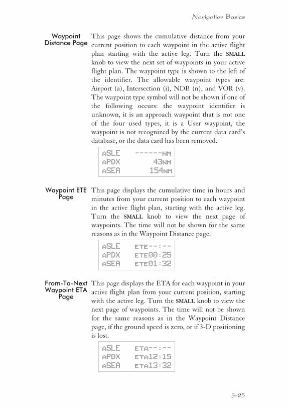
WaypointDistance Page
This page shows the cumulative distance from your
current position to each waypoint in the active flight
plan starting with the active leg. Turn the SMALL
knob to view the next set of waypoints in your active
flight plan. The waypoint type is shown to the left of
the identifier. The allowable waypoint types are:
Airport (a), Intersection (i), NDB (n), and VOR (v).
The waypoint type symbol will not be shown if one of
the following occurs: the waypoint identifier is
unknown, it is an approach waypoint that is not one
of the four used types, it is a User waypoint, the
waypoint is not recognized by the current data card’s
database, or the data card has been removed.
aSLE ------nm
aPDX 43nm
aSEA 154nm
Waypoint ETEPage
This page displays the cumulative time in hours and
minutes from your current position to each waypoint
in the active flight plan, starting with the active leg.
Turn the SMALL knob to view the next page of
waypoints. The time will not be shown for the same
reasons as in the Waypoint Distance page.
aSLE ete--:--
aPDX ete00:25
aSEA ete01:32
From-To-NextWaypoint ETA
Page
This page displays the ETA for each waypoint in your
active flight plan from your current position, starting
with the active leg. Turn the SMALL knob to view the
next page of waypoints. The time will not be shown
for the same reasons as in the Waypoint Distance
page, if the ground speed is zero, or if 3-D positioning
is lost.
aSLE eta--:--
aPDX eta12:15
aSEA eta13:32
3-25
Navigation Basics
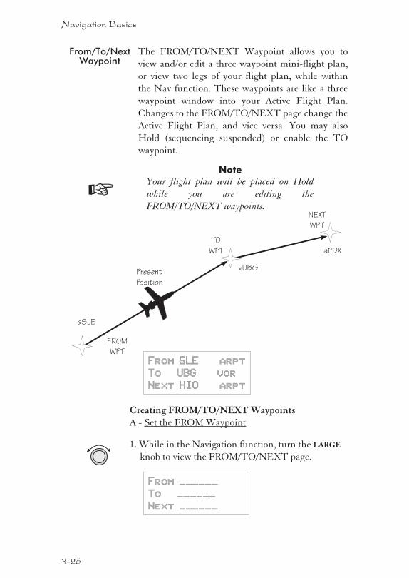
From/To/NextWaypoint
The FROM/TO/NEXT Waypoint allows you to
view and/or edit a three waypoint mini-flight plan,
or view two legs of your flight plan, while within
the Nav function. These waypoints are like a three
waypoint window into your Active Flight Plan.
Changes to the FROM/TO/NEXT page change the
Active Flight Plan, and vice versa. You may also
Hold (sequencing suspended) or enable the TO
waypoint.
Note
Your flight plan will be placed on Hold
while you are editing the
FROM/TO/NEXT waypoints.
From SLE arpt
To UBG vor
Next HIO arpt
Creating FROM/TO/NEXT WaypointsA - Set the FROM Waypoint
1. While in the Navigation function, turn the LARGE
knob to view the FROM/TO/NEXT page.
From ______
To ______
Next ______
3-26
Navigation Basics
TO
WPT
FROM
WPT
Present
Position
NEXT
WPT
vUBG
aPDX
aSLE
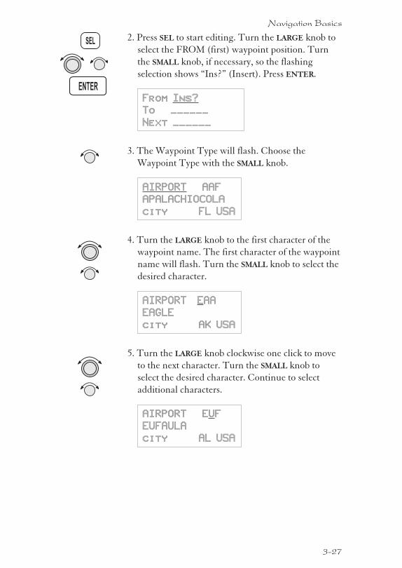
2. Press SEL to start editing. Turn the LARGE knob to
select the FROM (first) waypoint position. Turn
the SMALL knob, if necessary, so the flashing
selection shows “Ins?” (Insert). Press ENTER.
From Ins?
To ______
Next ______
3. The Waypoint Type will flash. Choose the
Waypoint Type with the SMALL knob.
AIRPORT AAF
APALACHIOCOLA
city FL USA
4. Turn the LARGE knob to the first character of the
waypoint name. The first character of the waypoint
name will flash. Turn the SMALL knob to select the
desired character.
AIRPORT EAA
EAGLE
city AK USA
5. Turn the LARGE knob clockwise one click to move
to the next character. Turn the SMALL knob to
select the desired character. Continue to select
additional characters.
AIRPORT EUF
EUFAULA
city AL USA
3-27
Navigation Basics
ENTER
SEL
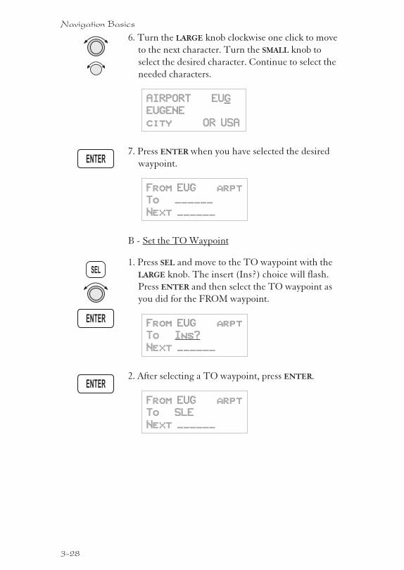
6. Turn the LARGE knob clockwise one click to move
to the next character. Turn the SMALL knob to
select the desired character. Continue to select the
needed characters.
AIRPORT EUG
EUGENE
city OR USA
7. Press ENTER when you have selected the desired
waypoint.
From EUG arpt
To ______
Next ______
B - Set the TO Waypoint
1. Press SEL and move to the TO waypoint with the
LARGE knob. The insert (Ins?) choice will flash.
Press ENTER and then select the TO waypoint as
you did for the FROM waypoint.
From EUG arpt
To Ins?
Next ______
2. After selecting a TO waypoint, press ENTER.
From EUG arpt
To SLE
Next ______
3-28
Navigation Basics
ENTER
SEL
ENTER
ENTER
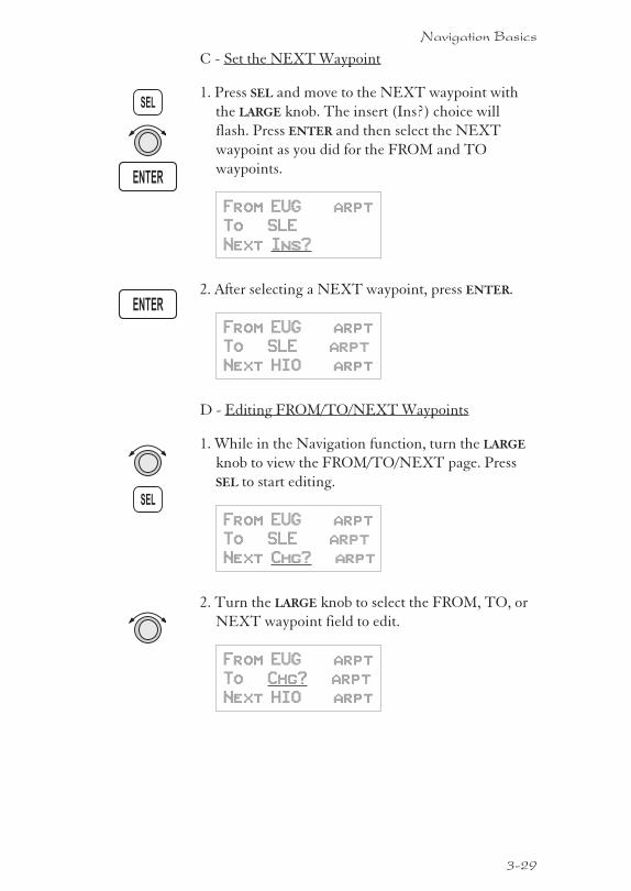
C - Set the NEXT Waypoint
1. Press SEL and move to the NEXT waypoint with
the LARGE knob. The insert (Ins?) choice will
flash. Press ENTER and then select the NEXT
waypoint as you did for the FROM and TO
waypoints.
From EUG arpt
To SLE
Next Ins?
2. After selecting a NEXT waypoint, press ENTER.
From EUG arpt
To SLE arpt
Next HIO arpt
D - Editing FROM/TO/NEXT Waypoints
1. While in the Navigation function, turn the LARGE
knob to view the FROM/TO/NEXT page. Press
SEL to start editing.
From EUG arpt
To SLE arpt
Next Chg? arpt
2. Turn the LARGE knob to select the FROM, TO, or
NEXT waypoint field to edit.
From EUG arpt
To Chg? arpt
Next HIO arpt
3-29
Navigation Basics
ENTER
SEL
ENTER
SEL
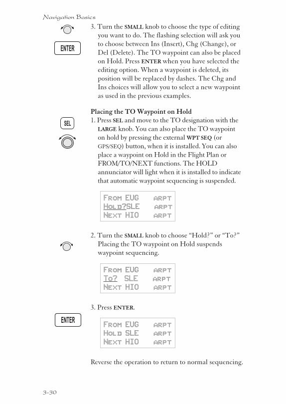
3. Turn the SMALL knob to choose the type of editing
you want to do. The flashing selection will ask you
to choose between Ins (Insert), Chg (Change), or
Del (Delete). The TO waypoint can also be placed
on Hold. Press ENTER when you have selected the
editing option. When a waypoint is deleted, its
position will be replaced by dashes. The Chg and
Ins choices will allow you to select a new waypoint
as used in the previous examples.
Placing the TO Waypoint on Hold1. Press SEL and move to the TO designation with the
LARGE knob. You can also place the TO waypoint
on hold by pressing the external WPT SEQ (or
GPS/SEQ) button, when it is installed. You can also
place a waypoint on Hold in the Flight Plan or
FROM/TO/NEXT functions. The HOLD
annunciator will light when it is installed to indicate
that automatic waypoint sequencing is suspended.
From EUG arpt
Hold?SLE arpt
Next HIO arpt
2. Turn the SMALL knob to choose “Hold?” or “To?”
Placing the TO waypoint on Hold suspends
waypoint sequencing.
From EUG arpt
To? SLE arpt
Next HIO arpt
3. Press ENTER.
From EUG arpt
Hold SLE arpt
Next HIO arpt
Reverse the operation to return to normal sequencing.
3-30
Navigation Basics
ENTER
SEL
ENTER
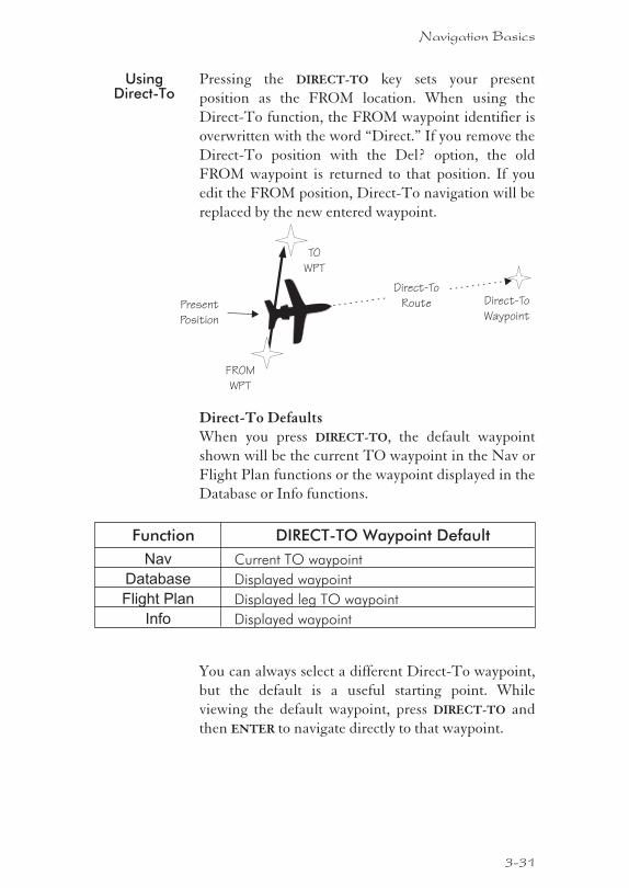
UsingDirect-To
Pressing the DIRECT-TO key sets your present
position as the FROM location. When using the
Direct-To function, the FROM waypoint identifier is
overwritten with the word “Direct.” If you remove the
Direct-To position with the Del? option, the old
FROM waypoint is returned to that position. If you
edit the FROM position, Direct-To navigation will be
replaced by the new entered waypoint.
Direct-To DefaultsWhen you press DIRECT-TO, the default waypoint
shown will be the current TO waypoint in the Nav or
Flight Plan functions or the waypoint displayed in the
Database or Info functions.
Function DIRECT-TO Waypoint Default
Nav Current TO waypoint
Database Displayed waypoint
Flight Plan Displayed leg TO waypoint
Info Displayed waypoint
You can always select a different Direct-To waypoint,
but the default is a useful starting point. While
viewing the default waypoint, press DIRECT-TO and
then ENTER to navigate directly to that waypoint.
3-31
Navigation Basics
FROM
WPT
Present
Position
TO
WPT
Direct-To
Route Direct-To
Waypoint
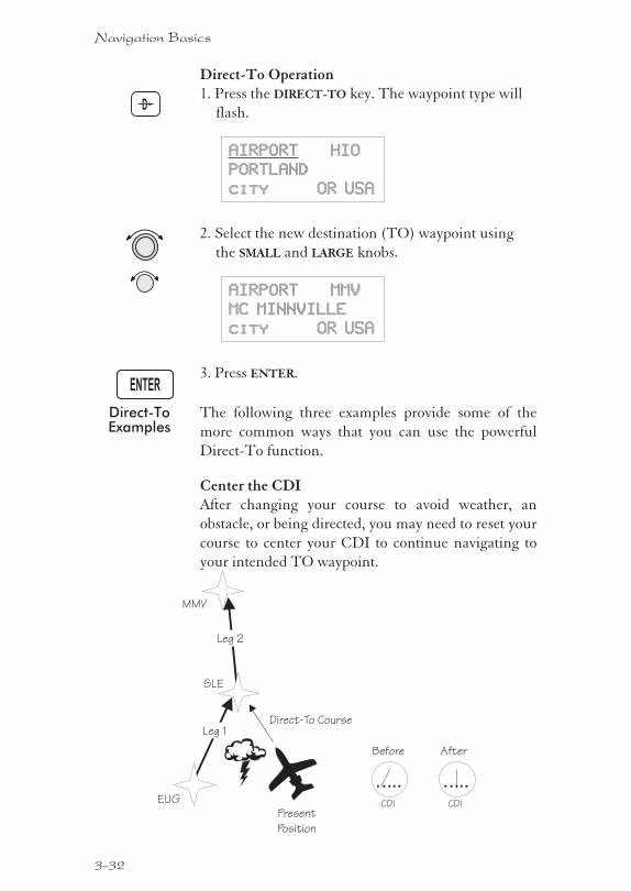
Direct-To Operation1. Press the DIRECT-TO key. The waypoint type will
flash.
AIRPORT HIO
PORTLAND
city OR USA
2. Select the new destination (TO) waypoint using
the SMALL and LARGE knobs.
AIRPORT MMV
MC MINNVILLE
city OR USA
3. Press ENTER.
Direct-ToExamples
The following three examples provide some of the
more common ways that you can use the powerful
Direct-To function.
Center the CDIAfter changing your course to avoid weather, an
obstacle, or being directed, you may need to reset your
course to center your CDI to continue navigating to
your intended TO waypoint.
3-32
Navigation Basics
Present
Position
SLE
MMV
Leg 1
Leg 2
CDIEUG CDI
Before After
Direct-To Course
ENTER
D
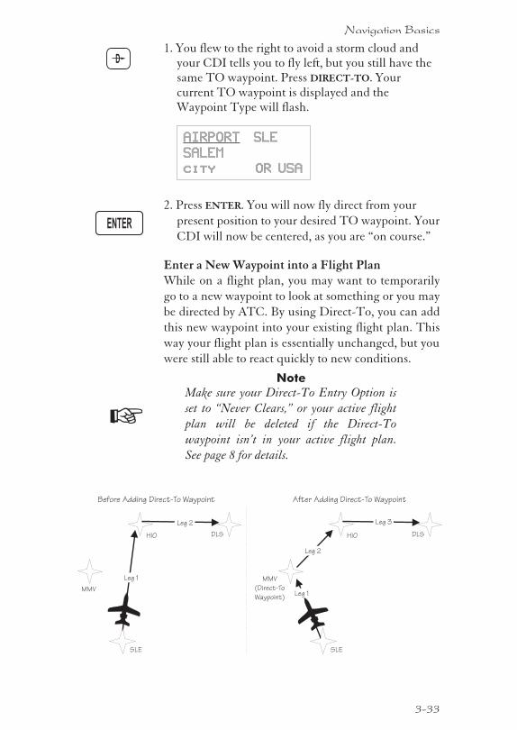
1. You flew to the right to avoid a storm cloud andyour CDI tells you to fly left, but you still have thesame TO waypoint. Press DIRECT-TO. Yourcurrent TO waypoint is displayed and theWaypoint Type will flash.
AIRPORT SLE
SALEM
city OR USA
2. Press ENTER. You will now fly direct from your
present position to your desired TO waypoint. Your
CDI will now be centered, as you are “on course.”
Enter a New Waypoint into a Flight PlanWhile on a flight plan, you may want to temporarily
go to a new waypoint to look at something or you may
be directed by ATC. By using Direct-To, you can add
this new waypoint into your existing flight plan. This
way your flight plan is essentially unchanged, but you
were still able to react quickly to new conditions.
Note
Make sure your Direct-To Entry Option is
set to “Never Clears,” or your active flight
plan will be deleted if the Direct-To
waypoint isn’t in your active flight plan.
See page 8 for details.
3-33
Navigation Basics
HIO
SLE
MMV
DLS
Leg 1
Leg 2
Before Adding Direct-To Waypoint
HIO
SLE
MMV
(Direct-To
Waypoint)
DLS
Leg 2
After Adding Direct-To Waypoint
Leg 1
Leg 3
ENTER
D
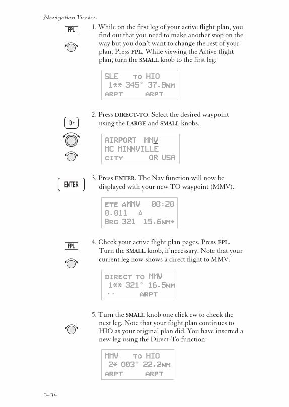
1. While on the first leg of your active flight plan, youfind out that you need to make another stop on theway but you don’t want to change the rest of yourplan. Press FPL. While viewing the Active flightplan, turn the SMALL knob to the first leg.
SLE to HIO
1** 345° 37.8nm
arpt arpt
2. Press DIRECT-TO. Select the desired waypoint
using the LARGE and SMALL knobs.
AIRPORT MMV
MC MINNVILLE
city OR USA
3. Press ENTER. The Nav function will now be
displayed with your new TO waypoint (MMV).
ete aMMV 00:20
0.011 “
Brg 321 15.6nm·
4. Check your active flight plan pages. Press FPL.
Turn the SMALL knob, if necessary. Note that your
current leg now shows a direct flight to MMV.
direct to MMV
1** 321° 16.5nm
—— arpt
5. Turn the SMALL knob one click cw to check thenext leg. Note that your flight plan continues toHIO as your original plan did. You have inserted anew leg using the Direct-To function.
MMV to HIO
2* 003° 22.2nm
arpt arpt
3-34
Navigation Basics
ENTER
D
FPL
FPL
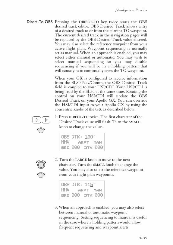
Direct-To OBS Pressing the DIRECT-TO key twice starts the OBSdesired track editor. OBS Desired Track allows entryof a desired track to or from the current TO waypoint.The current desired track in the navigation pages willbe replaced by the OBS Desired Track value entered.You may also select the reference waypoint from youractive flight plan. Waypoint sequencing is normallyset as manual. When an approach is enabled, you mayselect either manual or automatic. You may wish toselect manual sequencing so you may disablesequencing if you will be in a holding pattern thatwill cause you to continually cross the TO waypoint.
When your GX is configured to receive informationfrom the SL30 Nav/Comm, the OBS Desired Trackfield is coupled to your HSI/CDI. Your HSI/CDI isbeing read by the SL30 at the same time. Rotating thecontrol on your HSI/CDI will update the OBSDesired Track on your Apollo GX. You can overridethe HSI/CDI input to your Apollo GX by using theconcentric knobs of the GX as described below.
1. Press DIRECT-TO twice. The first character of theDesired Track value will flash. Turn the SMALL
knob to change the value.
OBS DTK: 100°
MMV arpt man
brg 000 dtk 000
2. Turn the LARGE knob to move to the nextcharacter. Turn the SMALL knob to change thevalue. You may also select the reference waypointfrom your flight plan waypoints.
OBS DTK: 115°
MMV arpt man
brg 000 dtk 000
3. When an approach is enabled, you may also selectbetween manual or automatic waypointsequencing. Setting sequencing to manual is usefulin the case where a holding pattern would allowfrequent sequencing and waypoint alerts.
3-35
Navigation Basics
D D
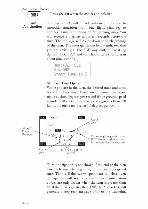
4. Press ENTER when the choices are selected.
TurnAnticipation
The Apollo GX will provide information for you to
smoothly transition from one flight plan leg to
another. Turns are drawn on the moving map. You
will receive a message about ten seconds before the
turn. The message will count down to the beginning
of the turn. The message shown below indicates that
you are arriving at the SLE waypoint, the next leg
desired track is 93°, and you should start your turn in
about nine seconds.
Arrival: SLE
Dtk 093°
Start Turn in 9
Standard Turn OperationWhile you are in the turn, the desired track and cross
track are determined based on the turn. Turns are
made at three degrees per second if the ground speed
is under 250 knots. If ground speed is greater than 250
knots, the turn rate is set at 1.5 degrees per second.
Turn anticipation is not shown if the end of the turn
extends beyond the beginning of the next anticipated
turn. That is, if the two waypoints are too close, turn
anticipation will not be shown. Turn anticipation
curves are only drawn when the turn is greater than
5°. If the turn is greater than 120°, the Apollo GX will
generate a step turn message prior to the waypoint.
3-36
Navigation Basics
AircraftPresentPosition
RouteLine
SLE
30
010
24.2
MMV
44S
7S5
SLE 6S4
RouteLine
Turn AnticipationCurves
If turn angle is greater than120º, the turn will start wellbefore reaching the waypoint
ENTER
Turn anticipation will not be available when
sequencing is on Hold; for the MAP or MAHP of an
approach; or for the “flyover” waypoints in an
approach.
Wind and Turn AnticipationThe graphic Turn Anticipation curve drawn on the
map display is based on your current ground speed.
Once you enter the turn, the graphic curve is no
longer updated. You may need to increase or decrease
your standard rate turn to compensate for wind. If
your installation includes a GPSS autopilot interface,
the Apollo GX will monitor your progress throughout
the turn and send corrections to the autopilot. Wind
conditions requiring steeper than maximum bank
angles may result in overshooting the new course line.
GPSS GPS Steering (GPSS) information is provided by
your Apollo GX when setup with a properly installed
autopilot. An autopilot guided by information from
your Apollo GX will be more accurate, faster
responding, and smoother than using a CDI. GPSS
works with the Flight Plan and Turn Anticipation
features to have your avionic equipment do more of
the work for you.
Standard GPSS OperationOperating your Apollo GX with an autopilot is
simple:
1) Select a waypoint or flight plan in the Apollo GX.
2) Select GPSS mode on the autopilot or on the
HDG/GPSS selector switch (see your autopilot
operating instructions).
3) Fly. Your Apollo GX will direct the autopilot.
3-37
Navigation Basics
Approach GPSS OperationWhen the autopilot is directed by GPSS, there are few
considerations when flying an approach.
� GPSS information will not be provided after youpass the MAP. You need to follow the directionspublished on the approach plate.
� When directed to the MAHP, use the Direct-Tofunction. GPSS information will now once againbe provided to the autopilot.
� Certain waypoints within an approach may becoded as “Fly-over” waypoints. Fly-overwaypoints must be overflown before starting yourturn to the next waypoint. A turn anticipationcurve will not be drawn for these Fly-overwaypoints. The GPSS information from yourApollo GX will handle this automatically.
GPSS RulesThere a few rules for providing valid GPSS
information to your autopilot. Your autopilot should
indicate when GPSS information is valid/invalid.
Refer to your autopilot operating instructions for
details.
Apollo GX Information
� Your ground speed must be more than 5 kts
� You are navigating to a waypoint (flight plan ordirect-to)
� You are on the TO side of the waypoint
� You are not executing Missed Approachprocedures
Autopilot Information
� Horizontal bank output from the Apollo GX tothe autopilot is limited to 30° or less
� Turn rate is 3°/sec at speeds less than 250 ktsTurn rate is 1.5°/sec at speeds greater than 250 kts
3-38
Navigation Basics
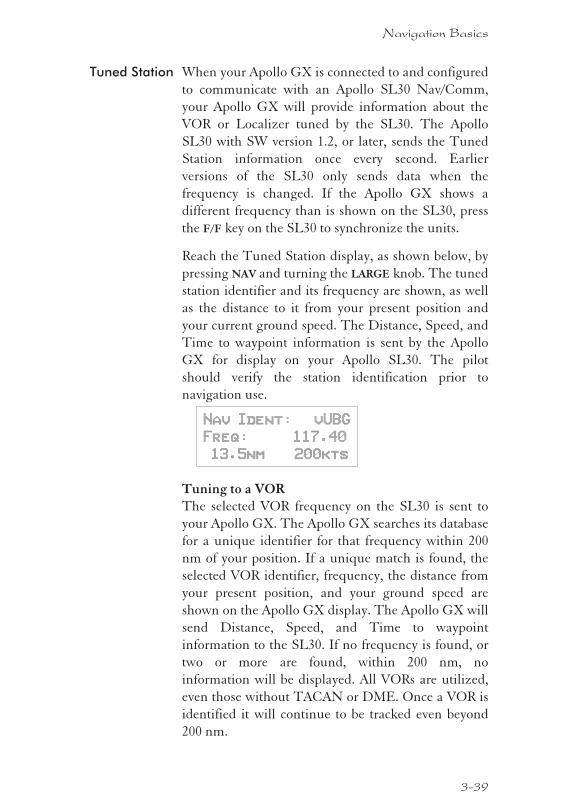
Tuned Station When your Apollo GX is connected to and configured
to communicate with an Apollo SL30 Nav/Comm,
your Apollo GX will provide information about the
VOR or Localizer tuned by the SL30. The Apollo
SL30 with SW version 1.2, or later, sends the Tuned
Station information once every second. Earlier
versions of the SL30 only sends data when the
frequency is changed. If the Apollo GX shows a
different frequency than is shown on the SL30, press
the F/F key on the SL30 to synchronize the units.
Reach the Tuned Station display, as shown below, by
pressing NAV and turning the LARGE knob. The tuned
station identifier and its frequency are shown, as well
as the distance to it from your present position and
your current ground speed. The Distance, Speed, and
Time to waypoint information is sent by the Apollo
GX for display on your Apollo SL30. The pilot
should verify the station identification prior to
navigation use.
Nav Ident: vUBG
Freq: 117.40
13.5nm 200kts
Tuning to a VORThe selected VOR frequency on the SL30 is sent to
your Apollo GX. The Apollo GX searches its database
for a unique identifier for that frequency within 200
nm of your position. If a unique match is found, the
selected VOR identifier, frequency, the distance from
your present position, and your ground speed are
shown on the Apollo GX display. The Apollo GX will
send Distance, Speed, and Time to waypoint
information to the SL30. If no frequency is found, or
two or more are found, within 200 nm, no
information will be displayed. All VORs are utilized,
even those without TACAN or DME. Once a VOR is
identified it will continue to be tracked even beyond
200 nm.
3-39
Navigation Basics
Tuning to a LocalizerWhen the connected SL30 is tuned to a Localizer
frequency, the SL30 sends the decoded Localizer
identifier to the Apollo GX. The Apollo GX searches
its LOC-DME database for an identifier match. If the
Localizer is found to be a co-located LOC-DME, the
Apollo GX will provide Distance, Speed, and Time
information to the SL30 and for the Tuned Station
page on the GX.
3-40
Navigation Basics
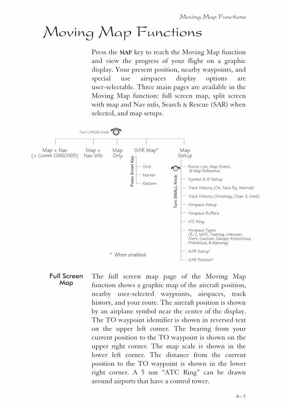
Moving Map FunctionsPress the MAP key to reach the Moving Map function
and view the progress of your flight on a graphic
display. Your present position, nearby waypoints, and
special use airspaces display options are
user-selectable. Three main pages are available in the
Moving Map function: full screen map, split screen
with map and Nav info, Search & Rescue (SAR) when
selected, and map setups.
Full ScreenMap
The full screen map page of the Moving Map
function shows a graphic map of the aircraft position,
nearby user-selected waypoints, airspaces, track
history, and your route. The aircraft position is shown
by an airplane symbol near the center of the display.
The TO waypoint identifier is shown in reversed text
on the upper left corner. The bearing from your
current position to the TO waypoint is shown on the
upper right corner. The map scale is shown in the
lower left corner. The distance from the current
position to the TO waypoint is shown in the lower
right corner. A 5 nm “ATC Ring” can be drawn
around airports that have a control tower.
Moving Map Functions
4-1
Tu
rnS
MA
LL
Kn
ob
Map + Nav(+ Comm GX60/65)
Map +Nav Info
MapOnly
Turn LARGE Knob
MapSetup
Route Line, Map Orient,& Map Reference
Symbol & ID Setup
Airspace Setup
Airspace Buffers
ATC Ring
Airspace Types(B, C, MOA, Training, Unknown,Alert, Caution, Danger, Restricted,Prohibited, & Warning)
SAR Setup*
SAR Position*
Track History (On, Save By, Interval)
Track History (Strategy, Clear, % Used)
SAR Map*
Grid
Marker
PatternPre
ss
Sm
art
Ke
y
* When enabled
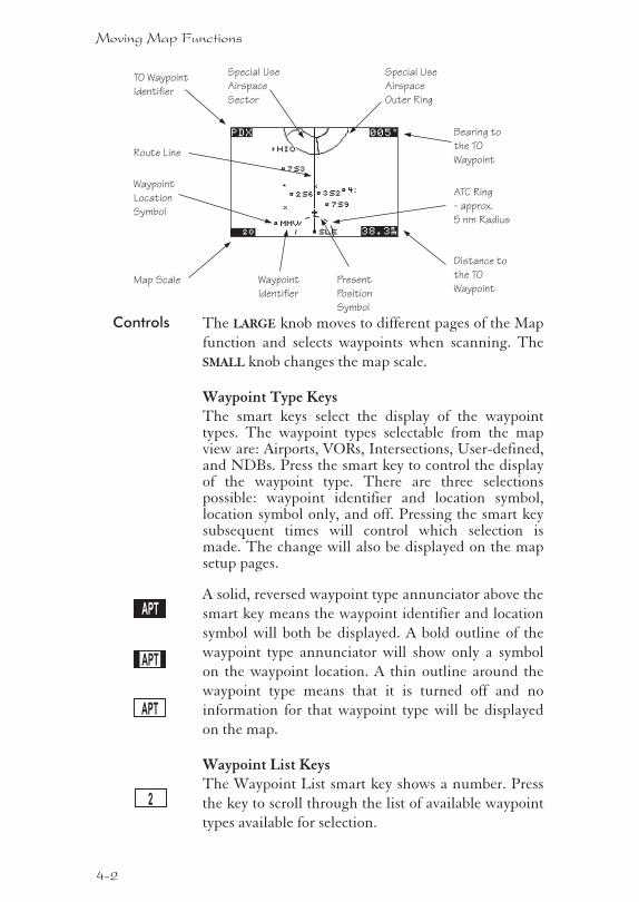
Controls The LARGE knob moves to different pages of the Map
function and selects waypoints when scanning. The
SMALL knob changes the map scale.
Waypoint Type KeysThe smart keys select the display of the waypointtypes. The waypoint types selectable from the mapview are: Airports, VORs, Intersections, User-defined,and NDBs. Press the smart key to control the displayof the waypoint type. There are three selectionspossible: waypoint identifier and location symbol,location symbol only, and off. Pressing the smart keysubsequent times will control which selection ismade. The change will also be displayed on the mapsetup pages.
A solid, reversed waypoint type annunciator above the
smart key means the waypoint identifier and location
symbol will both be displayed. A bold outline of the
waypoint type annunciator will show only a symbol
on the waypoint location. A thin outline around the
waypoint type means that it is turned off and no
information for that waypoint type will be displayed
on the map.
Waypoint List KeysThe Waypoint List smart key shows a number. Press
the key to scroll through the list of available waypoint
types available for selection.
4-2
Moving Map Functions
APT
APT
APT
2
TO Waypoint
Identifier
Map Scale
Special Use
Airspace
Outer Ring
Special Use
Airspace
Sector
Bearing to
the TO
Waypoint
Distance to
the TO
Waypoint
Route Line
Waypoint
Identifier
Waypoint
Location
Symbol
Present
Position
Symbol
ATC Ring
- approx.
5 nm Radius
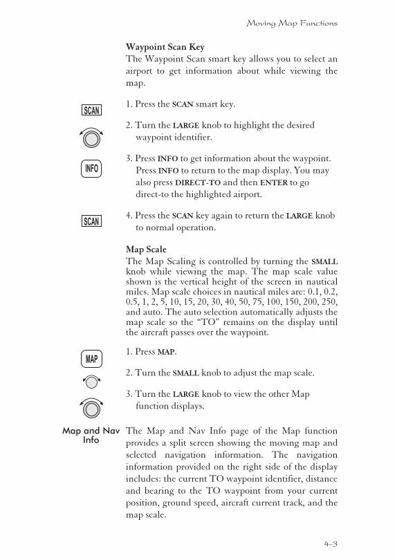
Waypoint Scan KeyThe Waypoint Scan smart key allows you to select an
airport to get information about while viewing the
map.
1. Press the SCAN smart key.
2. Turn the LARGE knob to highlight the desired
waypoint identifier.
3. Press INFO to get information about the waypoint.
Press INFO to return to the map display. You may
also press DIRECT-TO and then ENTER to go
direct-to the highlighted airport.
4. Press the SCAN key again to return the LARGE knob
to normal operation.
Map ScaleThe Map Scaling is controlled by turning the SMALL
knob while viewing the map. The map scale valueshown is the vertical height of the screen in nauticalmiles. Map scale choices in nautical miles are: 0.1, 0.2,0.5, 1, 2, 5, 10, 15, 20, 30, 40, 50, 75, 100, 150, 200, 250,and auto. The auto selection automatically adjusts themap scale so the “TO” remains on the display untilthe aircraft passes over the waypoint.
1. Press MAP.
2. Turn the SMALL knob to adjust the map scale.
3. Turn the LARGE knob to view the other Map
function displays.
Map and NavInfo
The Map and Nav Info page of the Map function
provides a split screen showing the moving map and
selected navigation information. The navigation
information provided on the right side of the display
includes: the current TO waypoint identifier, distance
and bearing to the TO waypoint from your current
position, ground speed, aircraft current track, and the
map scale.
4-3
Moving Map Functions
MAP
SCAN
INFO
SCAN
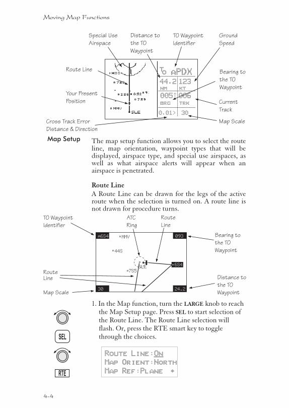
Map Setup The map setup function allows you to select the routeline, map orientation, waypoint types that will bedisplayed, airspace type, and special use airspaces, aswell as what airspace alerts will appear when anairspace is penetrated.
Route LineA Route Line can be drawn for the legs of the activeroute when the selection is turned on. A route line isnot drawn for procedure turns.
1. In the Map function, turn the LARGE knob to reachthe Map Setup page. Press SEL to start selection ofthe Route Line. The Route Line selection willflash. Or, press the RTE smart key to togglethrough the choices.
Route Line:On
Map Orient:North
Map Ref:Plane ·
4-4
Moving Map Functions
SEL
RTE
TO Waypoint
Identifier
Map Scale
Bearing to
the TO
Waypoint
Distance to
the TO
Waypoint
RouteLine
a6S4
30
093
24.2
MMV
44S
7S5SLE
6S4
Route
Line
ATC
Ring
TO Waypoint
Identifier
Cross Track Error
Distance & Direction
Bearing to
the TO
Waypoint
Distance to
the TO
Waypoint
Ground
Speed
Current
Track
Map Scale
aPDX
44.2
005½
123
006brg trk
nm kt
0.01> 30
to
Route Line
Your Present
Position
Special Use
Airspace
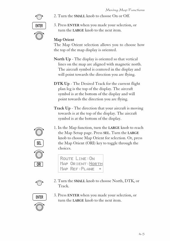
2. Turn the SMALL knob to choose On or Off.
3. Press ENTER when you made your selection, or
turn the LARGE knob to the next item.
Map OrientThe Map Orient selection allows you to choose how
the top of the map display is oriented.
North Up - The display is oriented so that vertical
lines on the map are aligned with magnetic north.
The aircraft symbol is centered in the display and
will point towards the direction you are flying.
DTK Up - The Desired Track for the current flight
plan leg is the top of the display. The aircraft
symbol is at the bottom of the display and will
point towards the direction you are flying.
Track Up - The direction that your aircraft is moving
towards is at the top of the display. The aircraft
symbol is at the bottom of the display.
1. In the Map function, turn the LARGE knob to reach
the Map Setup page. Press SEL. Turn the LARGE
knob to choose Map Orient for selection. Or, press
the Map Orient (ORI) key to toggle through the
choices.
Route Line:On
Map Orient:North
Map Ref:Plane ·
2. Turn the SMALL knob to choose North, DTK, or
Track.
3. Press ENTER when you made your selection, or
turn the LARGE knob to the next item.
4-5
Moving Map Functions
ENTER
SEL
ENTER
ORI
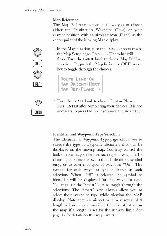
Map ReferenceThe Map Reference selection allows you to choose
either the Destination Waypoint (Dest) or your
current position with an airplane icon (Plane) as the
center point of the Moving Map display.
1. In the Map function, turn the LARGE knob to reach
the Map Setup page. Press SEL. The value will
flash. Turn the LARGE knob to choose Map Ref for
selection. Or, press the Map Reference (REF) smart
key to toggle through the choices.
Route Line:On
Map Orient:North
Map Ref:Plane ·
2. Turn the SMALL knob to choose Dest or Plane.
Press ENTER after completing your choices. It is not
necessary to press ENTER if you used the smart key.
Identifier and Waypoint Type SelectionThe Identifier & Waypoint Type page allows you to
choose the type of waypoint identifiers that will be
displayed on the moving map. You may control the
look of your map screen for each type of waypoint by
choosing to show the symbol and Identifier, symbol
only, or to turn that type of waypoint “Off.” The
symbol for each waypoint type is shown in each
selection. When “Off” is selected, no symbol or
identifier will be displayed for that waypoint type.
You may use the “smart” keys to toggle through the
selections. The “smart” keys always allow you to
select their waypoint type while viewing the MAP
display. Note that an airport with a runway of 0
length will not appear on either the nearest list, or on
the map if a length is set for the runway limit. See
page 12 for details on Runway Limits.
4-6
Moving Map Functions
ENTER
SEL
REF
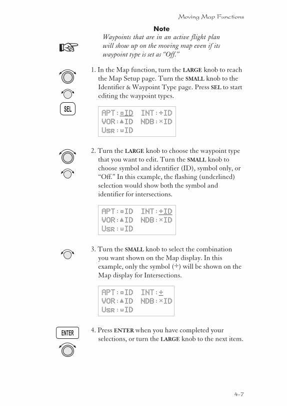
Note
Waypoints that are in an active flight plan
will show up on the moving map even if its
waypoint type is set as “Off.”
1. In the Map function, turn the LARGE knob to reach
the Map Setup page. Turn the SMALL knob to the
Identifier & Waypoint Type page. Press SEL to start
editing the waypoint types.
APT:¿ID INT:+ID
VOR:ÂID NDB:ÁID
Usr:ÀID
2. Turn the LARGE knob to choose the waypoint type
that you want to edit. Turn the SMALL knob to
choose symbol and identifier (ID), symbol only, or
“Off.” In this example, the flashing (underlined)
selection would show both the symbol and
identifier for intersections.
APT:¿ID INT:+ID
VOR:ÂID NDB:ÁID
Usr:ÀID
3. Turn the SMALL knob to select the combination
you want shown on the Map display. In this
example, only the symbol (+) will be shown on the
Map display for Intersections.
APT:¿ID INT:+
VOR:ÂID NDB:ÁID
Usr:ÀID
4. Press ENTER when you have completed your
selections, or turn the LARGE knob to the next item.
4-7
Moving Map Functions
SEL
ENTER
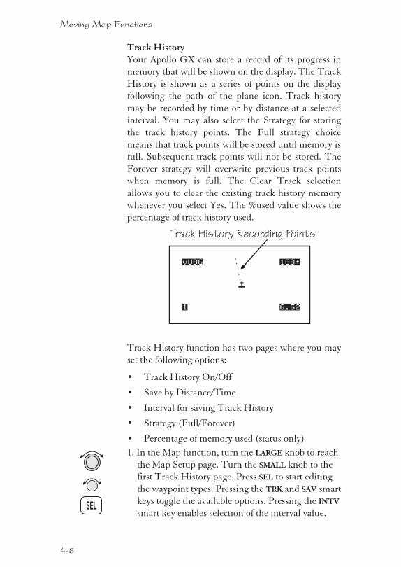
Track HistoryYour Apollo GX can store a record of its progress in
memory that will be shown on the display. The Track
History is shown as a series of points on the display
following the path of the plane icon. Track history
may be recorded by time or by distance at a selected
interval. You may also select the Strategy for storing
the track history points. The Full strategy choice
means that track points will be stored until memory is
full. Subsequent track points will not be stored. The
Forever strategy will overwrite previous track points
when memory is full. The Clear Track selection
allows you to clear the existing track history memory
whenever you select Yes. The %used value shows the
percentage of track history used.
Track History function has two pages where you may
set the following options:
� Track History On/Off
� Save by Distance/Time
� Interval for saving Track History
� Strategy (Full/Forever)
� Percentage of memory used (status only)
1. In the Map function, turn the LARGE knob to reach
the Map Setup page. Turn the SMALL knob to the
first Track History page. Press SEL to start editing
the waypoint types. Pressing the TRK and SAV smart
keys toggle the available options. Pressing the INTV
smart key enables selection of the interval value.
4-8
Moving Map Functions
SEL
Track History Recording Points
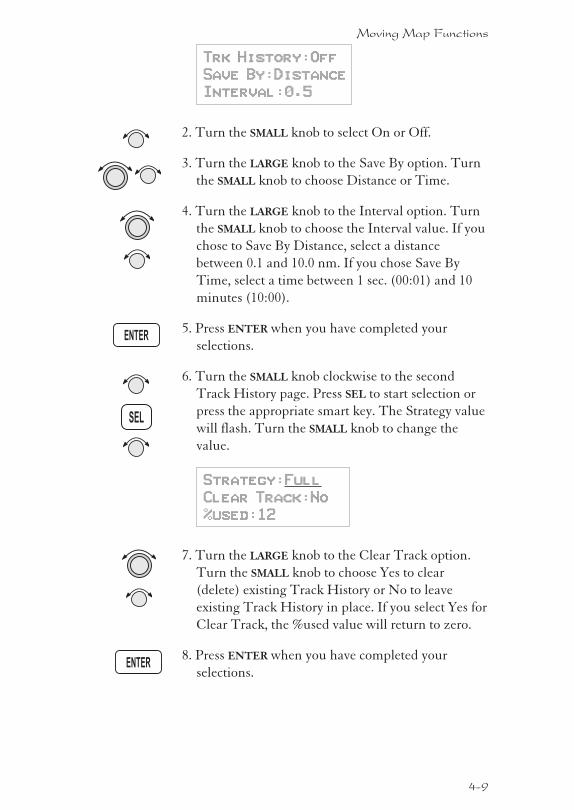
Trk History:Off
Save By:Distance
Interval:0.5
2. Turn the SMALL knob to select On or Off.
3. Turn the LARGE knob to the Save By option. Turn
the SMALL knob to choose Distance or Time.
4. Turn the LARGE knob to the Interval option. Turn
the SMALL knob to choose the Interval value. If you
chose to Save By Distance, select a distance
between 0.1 and 10.0 nm. If you chose Save By
Time, select a time between 1 sec. (00:01) and 10
minutes (10:00).
5. Press ENTER when you have completed your
selections.
6. Turn the SMALL knob clockwise to the second
Track History page. Press SEL to start selection or
press the appropriate smart key. The Strategy value
will flash. Turn the SMALL knob to change the
value.
Strategy:Full
Clear Track:No
%used:12
7. Turn the LARGE knob to the Clear Track option.
Turn the SMALL knob to choose Yes to clear
(delete) existing Track History or No to leave
existing Track History in place. If you select Yes for
Clear Track, the %used value will return to zero.
8. Press ENTER when you have completed your
selections.
4-9
Moving Map Functions
SEL
ENTER
ENTER
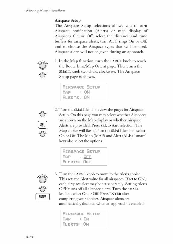
Airspace SetupThe Airspace Setup selections allows you to turn
Airspace notification (Alerts) or map display of
Airspaces On or Off, select the distance and time
buffers for airspace alerts, turn ATC rings On or Off,
and to choose the Airspace types that will be used.
Airspace alerts will not be given during an approach.
1. In the Map function, turn the LARGE knob to reach
the Route Line/Map Orient page. Then, turn the
SMALL knob two clicks clockwise. The Airspace
Setup page is shown.
Airspace Setup
Map : ON
Alerts: ON
2. Turn the SMALL knob to view the pages for Airspace
Setup. On this page you may select whether Airspaces
are shown on the Map display or whether Airspace
Alerts are provided. Press SEL to start selection. The
Map choice will flash. Turn the SMALL knob to select
On or Off. The Map (MAP) and Alert (ALE) “smart”
keys also select the options.
Airspace Setup
Map : Off
Alerts: Off
3. Turn the LARGE knob to move to the Alerts choice.This sets the Alert value for all airspaces. If set to ON,each airspace alert may be set separately. Setting AlertsOFF turns off all airspace alerts. Turn the SMALL
knob to select On or Off. Press ENTER aftercompleting your choices. Airspace alerts areautomatically disabled when an approach is enabled.
Airspace Setup
Map : On
Alerts: On
4-10
Moving Map Functions
SEL
ENTER
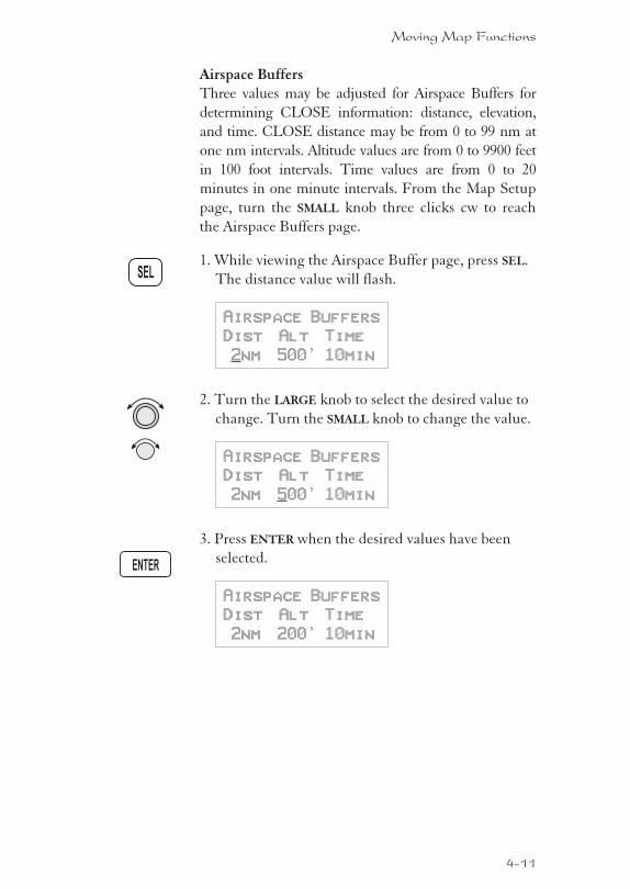
Airspace BuffersThree values may be adjusted for Airspace Buffers for
determining CLOSE information: distance, elevation,
and time. CLOSE distance may be from 0 to 99 nm at
one nm intervals. Altitude values are from 0 to 9900 feet
in 100 foot intervals. Time values are from 0 to 20
minutes in one minute intervals. From the Map Setup
page, turn the SMALL knob three clicks cw to reach
the Airspace Buffers page.
1. While viewing the Airspace Buffer page, press SEL.
The distance value will flash.
Airspace Buffers
Dist Alt Time
2nm 500’ 10min
2. Turn the LARGE knob to select the desired value to
change. Turn the SMALL knob to change the value.
Airspace Buffers
Dist Alt Time
2nm 500’ 10min
3. Press ENTER when the desired values have been
selected.
Airspace Buffers
Dist Alt Time
2nm 200’ 10min
4-11
Moving Map Functions
SEL
ENTER

ATC Ring SelectionWhen this choice is turned ON, a 5 nm radiusartificial “ATC Ring” is drawn on the Map displayaround airports that have a control tower. From theMap Setup page, turn the SMALL knob four clicks cwto reach the ATC Ring selection page.
1. While viewing the ATC Ring page, press SEL tostart selection.
5 nm ATC Rings
Map : Off
2. Turn the SMALL knob to choose ON or OFF. PressENTER after completing your selection.
5 nm ATC Rings
Map : On
Airspace SelectionsThe Airspaces available for selection are: Class B (Off,Outer, or Sector), Class C (Off, Outer, or Sector),MOA, Training, Unknown, Alert, Caution, Danger,Restricted, Prohibited, and Warning. You may selectON or OFF for map display and alerts for eachAirspace type.
4-12
Moving Map Functions
Outer Sector
SEL
ENTER
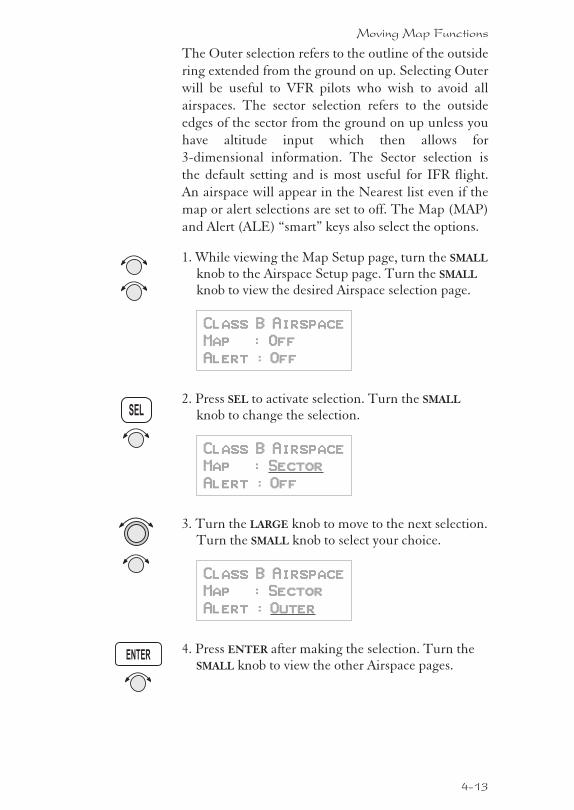
The Outer selection refers to the outline of the outside
ring extended from the ground on up. Selecting Outer
will be useful to VFR pilots who wish to avoid all
airspaces. The sector selection refers to the outside
edges of the sector from the ground on up unless you
have altitude input which then allows for
3-dimensional information. The Sector selection is
the default setting and is most useful for IFR flight.
An airspace will appear in the Nearest list even if the
map or alert selections are set to off. The Map (MAP)
and Alert (ALE) “smart” keys also select the options.
1. While viewing the Map Setup page, turn the SMALL
knob to the Airspace Setup page. Turn the SMALL
knob to view the desired Airspace selection page.
Class B Airspace
Map : Off
Alert : Off
2. Press SEL to activate selection. Turn the SMALL
knob to change the selection.
Class B Airspace
Map : Sector
Alert : Off
3. Turn the LARGE knob to move to the next selection.Turn the SMALL knob to select your choice.
Class B Airspace
Map : Sector
Alert : Outer
4. Press ENTER after making the selection. Turn theSMALL knob to view the other Airspace pages.
4-13
Moving Map Functions
SEL
ENTER
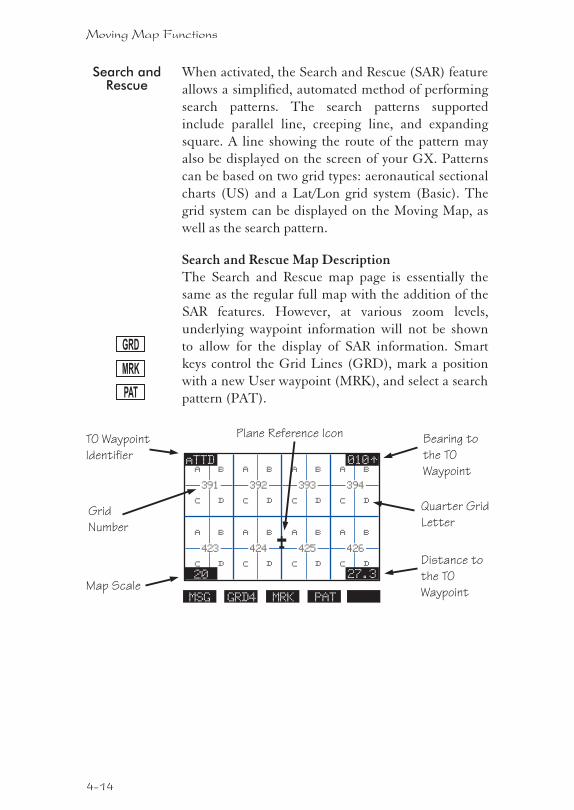
Search andRescue
When activated, the Search and Rescue (SAR) feature
allows a simplified, automated method of performing
search patterns. The search patterns supported
include parallel line, creeping line, and expanding
square. A line showing the route of the pattern may
also be displayed on the screen of your GX. Patterns
can be based on two grid types: aeronautical sectional
charts (US) and a Lat/Lon grid system (Basic). The
grid system can be displayed on the Moving Map, as
well as the search pattern.
Search and Rescue Map DescriptionThe Search and Rescue map page is essentially the
same as the regular full map with the addition of the
SAR features. However, at various zoom levels,
underlying waypoint information will not be shown
to allow for the display of SAR information. Smart
keys control the Grid Lines (GRD), mark a position
with a new User waypoint (MRK), and select a search
pattern (PAT).
4-14
Moving Map Functions
GRD
426
a b
c d
423
a b
c d
394
a b
c d
TO Waypoint
Identifier
Map Scale
Bearing to
the TO
Waypoint
Distance to
the TO
Waypoint
393
a b
c dQuarter Grid
LetterGrid
Number
20 27.3
010TT
392
a b
c d
391
a b
c d
425
a b
c d
424
a b
c d
aTTD
GRD4MSG PATMRK
Plane Reference Icon
MRK
PAT
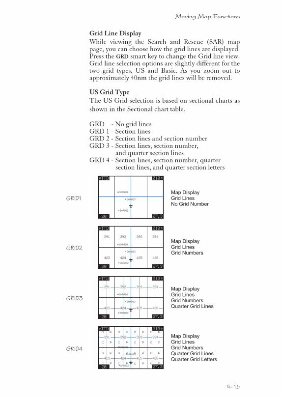
Grid Line DisplayWhile viewing the Search and Rescue (SAR) mappage, you can choose how the grid lines are displayed.Press the GRD smart key to change the Grid line view.Grid line selection options are slightly different for thetwo grid types, US and Basic. As you zoom out toapproximately 40nm the grid lines will be removed.
US Grid TypeThe US Grid selection is based on sectional charts as
shown in the Sectional chart table.
GRD - No grid linesGRD 1 - Section linesGRD 2 - Section lines and section numberGRD 3 - Section lines, section number,
and quarter section linesGRD 4 - Section lines, section number, quarter
section lines, and quarter section letters
4-15
Moving Map Functions
20 27.3
010TTaTTD
426423
394393
20 27.3
010TT
392391
425424
aTTD
426423
394393
20 27.3
010TT
392391
425424
aTTD
426
a b
c d
423
a b
c d
394
a b
c d
393
a b
c d
20 27.3
010TT
392
a b
c d
391
a b
c d
425
a b
c d
424
a b
c d
aTTD
GRID1
GRID2
GRID3
GRID4
SAR003
SAR000
SAR002
SAR003
SAR000
SAR002
SAR003
SAR000
SAR002
SAR003
SAR000
SAR002
Map DisplayGrid LinesNo Grid Number
Map DisplayGrid LinesGrid Numbers
Map DisplayGrid LinesGrid NumbersQuarter Grid Lines
Map DisplayGrid LinesGrid NumbersQuarter Grid LinesQuarter Grid Letters
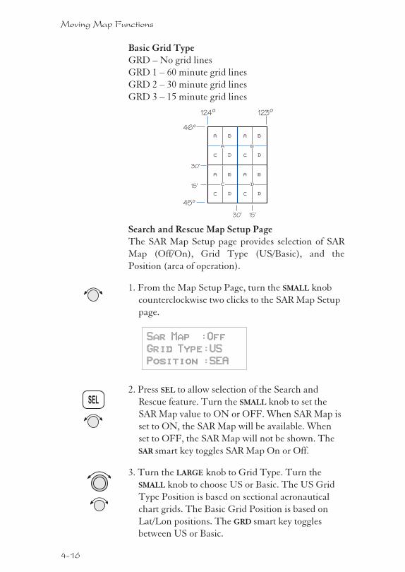
Basic Grid TypeGRD – No grid lines
GRD 1 – 60 minute grid lines
GRD 2 – 30 minute grid lines
GRD 3 – 15 minute grid lines
Search and Rescue Map Setup PageThe SAR Map Setup page provides selection of SAR
Map (Off/On), Grid Type (US/Basic), and the
Position (area of operation).
1. From the Map Setup Page, turn the SMALL knob
counterclockwise two clicks to the SAR Map Setup
page.
Sar Map :Off
Grid Type:US
Position :SEA
2. Press SEL to allow selection of the Search and
Rescue feature. Turn the SMALL knob to set the
SAR Map value to ON or OFF. When SAR Map is
set to ON, the SAR Map will be available. When
set to OFF, the SAR Map will not be shown. The
SAR smart key toggles SAR Map On or Off.
3. Turn the LARGE knob to Grid Type. Turn the
SMALL knob to choose US or Basic. The US Grid
Type Position is based on sectional aeronautical
chart grids. The Basic Grid Position is based on
Lat/Lon positions. The GRD smart key toggles
between US or Basic.
4-16
Moving Map Functions
SEL
a b
c d
a b
c d
a b
c d
a b
c d
a b
c d
45º
46º
123º124º
30’ 15’
30’
15’
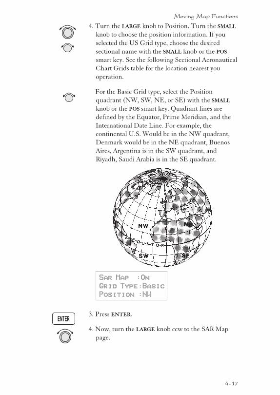
4. Turn the LARGE knob to Position. Turn the SMALL
knob to choose the position information. If you
selected the US Grid type, choose the desired
sectional name with the SMALL knob or the POS
smart key. See the following Sectional Aeronautical
Chart Grids table for the location nearest you
operation.
For the Basic Grid type, select the Position
quadrant (NW, SW, NE, or SE) with the SMALL
knob or the POS smart key. Quadrant lines are
defined by the Equator, Prime Meridian, and the
International Date Line. For example, the
continental U.S. Would be in the NW quadrant,
Denmark would be in the NE quadrant, Buenos
Aires, Argentina is in the SW quadrant, and
Riyadh, Saudi Arabia is in the SE quadrant.
Sar Map :On
Grid Type:Basic
Position :NW
3. Press ENTER.
4. Now, turn the LARGE knob ccw to the SAR Map
page.
4-17
Moving Map Functions
ENTER
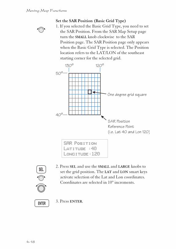
Set the SAR Position (Basic Grid Type)1. If you selected the Basic Grid Type, you need to set
the SAR Position. From the SAR Map Setup page
turn the SMALL knob clockwise to the SAR
Position page. The SAR Position page only appears
when the Basic Grid Type is selected. The Position
location refers to the LAT/LON of the southeast
starting corner for the selected grid.
SAR Position
Latitude :40
Longitude:120
2. Press SEL and use the SMALL and LARGE knobs to
set the grid position. The LAT and LON smart keys
activate selection of the Lat and Lon coordinates.
Coordinates are selected in 10º increments.
3. Press ENTER.
4-18
Moving Map Functions
ENTER
SEL
40º
50º
120º130º
SAR Position
Reference Point
(i.e. Lat 40 and Lon 120)
One degree grid square
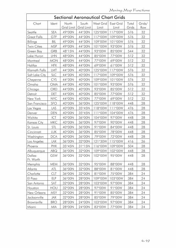
Sectional Aeronautical Chart Grids
Chart Ident NorthGrid Limit
SouthGrid Limit
West GridLimit
East GridLimit
TotalGrids
Grids/Row
Seattle SEA 49�00N 44�30N 125�00W 117�00W 576 32
Great Falls GTF 49�00N 44�30N 117�00W 109�00W 576 32
Billings BIL 49�00N 44�30N 109°00W 101�00W 576 32
Twin Cities MSP 49�00N 44�30N 101�00W 93�00W 576 32
Green Bay GRB 48°15N 44�00N 93�00W 85�00W 544 32
Lake Huron LHN 48�00N 44�00N 85�00W 77�00W 512 32
Montreal MON 48�00N 44�00N 77�00W 69�00W 512 32
Halifax HFX 48�00N 44�00N 69�00W 61�00W 512 32
Klamath Falls LMT 44�30N 40�00N 125�00W 117�00W 576 32
Salt Lake City SLC 44�30N 40°00N 117�00W 109�00W 576 32
Cheyenne CYS 44�30N 40�00N 109�00W 101�00W 576 32
Omaha OMA 44�30N 40�00N 101�00W 93�00W 576 32
Chicago ORD 44�00N 40�00N 93�00W 85�00W 512 32
Detroit DET 44�00N 40�00N 85�00W 77�00W 512 32
New York NYC 44�00N 40°00N 77�00W 69�00W 512 32
San Francisco SFO 40�00N 36�00N 125�00W 118�00W 448 28
Las Vegas LAS 40�00N 35�45N 118�00W 111�00W 476 28
Denver DEN 40�00N 35�45N 111�00W 104�00W 476 28
Wichita ICT 40�00N 36�00N 104�00W 97�00W 448 28
Kansas City MKC 40�00N 36�00N 97�00W 90�00W 448 28
St. Louis STL 40�00N 36�00N 91�00W 84�00W 448 28
Cincinnati LUK 40�00N 36�00N 85�00W 78�00W 448 28
Washington DCA 40�00N 36�00N 79�00W 72�00W 448 28
Los Angeles LAX 36�00N 32�00N 121�30W 115�00W 416 26
Phoenix PHX 35�45N 31�15N 116�00W 109�00W 504 28
Albuquerque ABQ 36�00N 32�00N 109�00W 102�00W 448 28
Dallas-Ft. Worth
GSW 36�00N 32�00N 102�00W 95�00W 448 28
Memphis MEM 36�00N 32�00N 95�00W 88�00W 448 28
Atlanta ATL 36�00N 32�00N 88�00W 81�00W 448 28
Charlotte CLT 36�00N 32�00N 81�00W 75�00W 384 24
El Paso ELP 36�00N 28�00N 109�00W 103�00W 384 24
San Antonio SAT 32�00N 28�00N 103�00W 97�00W 384 24
Houston HOU 32�00N 28�00N 97�00W 91�00W 384 24
New Orleans MSY 32�00N 28�00N 91�00W 85�00W 384 24
Jacksonville JAX 32�00N 28�00N 85�00W 79�00W 384 24
Brownsville BRO 28�00N 24�00N 103�00W 97�00W 384 24
Miami MIA 28�00N 24�00N 83�00W 77�00W 384 24
4-19
Moving Map Functions
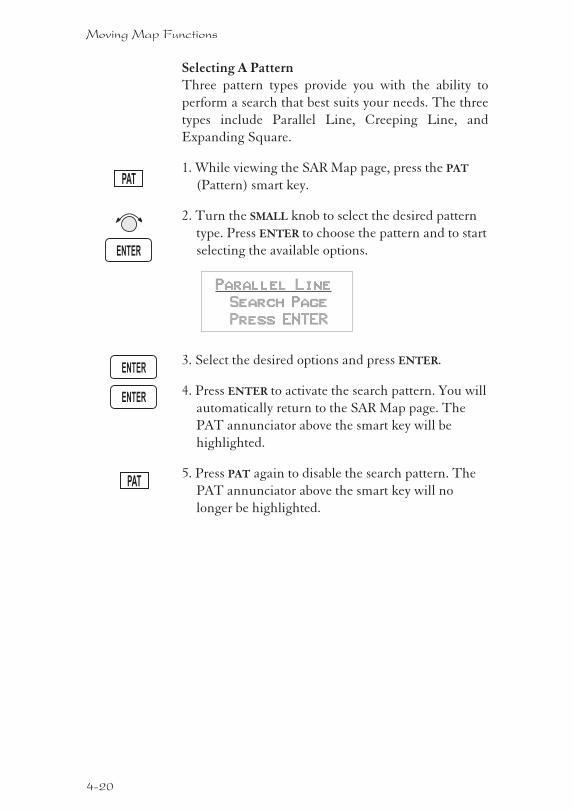
Selecting A PatternThree pattern types provide you with the ability to
perform a search that best suits your needs. The three
types include Parallel Line, Creeping Line, and
Expanding Square.
1. While viewing the SAR Map page, press the PAT
(Pattern) smart key.
2. Turn the SMALL knob to select the desired pattern
type. Press ENTER to choose the pattern and to start
selecting the available options.
Parallel Line
Search Page
Press ENTER
3. Select the desired options and press ENTER.
4. Press ENTER to activate the search pattern. You will
automatically return to the SAR Map page. The
PAT annunciator above the smart key will be
highlighted.
5. Press PAT again to disable the search pattern. The
PAT annunciator above the smart key will no
longer be highlighted.
4-20
Moving Map Functions
ENTER
PAT
PAT
ENTER
ENTER
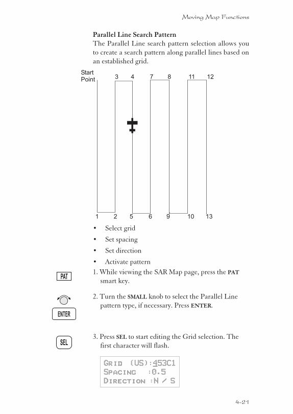
Parallel Line Search PatternThe Parallel Line search pattern selection allows you
to create a search pattern along parallel lines based on
an established grid.
� Select grid
� Set spacing
� Set direction
� Activate pattern
1. While viewing the SAR Map page, press the PAT
smart key.
2. Turn the SMALL knob to select the Parallel Line
pattern type, if necessary. Press ENTER.
3. Press SEL to start editing the Grid selection. The
first character will flash.
Grid (US):453C1
Spacing :0.5
Direction :N / S
4-21
Moving Map Functions
ENTER
SEL
PAT
1 2 5 6 9 10 13
3 4 7 8 11 12StartPoint
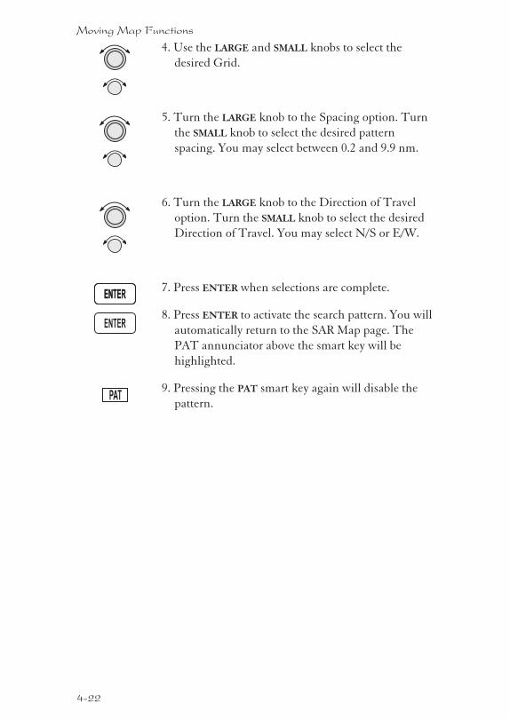
4. Use the LARGE and SMALL knobs to select the
desired Grid.
5. Turn the LARGE knob to the Spacing option. Turn
the SMALL knob to select the desired pattern
spacing. You may select between 0.2 and 9.9 nm.
6. Turn the LARGE knob to the Direction of Travel
option. Turn the SMALL knob to select the desired
Direction of Travel. You may select N/S or E/W.
7. Press ENTER when selections are complete.
8. Press ENTER to activate the search pattern. You will
automatically return to the SAR Map page. The
PAT annunciator above the smart key will be
highlighted.
9. Pressing the PAT smart key again will disable the
pattern.
4-22
Moving Map Functions
ENTER
PAT
ENTER
ENTER
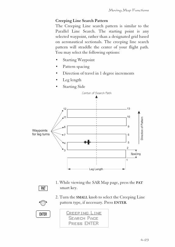
Creeping Line Search PatternThe Creeping Line search pattern is similar to the
Parallel Line Search. The starting point is any
selected waypoint, rather than a designated grid based
on aeronautical sectionals. The creeping line search
pattern will straddle the center of your flight path.
You may select the following options:
� Starting Waypoint
� Pattern spacing
� Direction of travel in 1 degree increments
� Leg length
� Starting Side
1. While viewing the SAR Map page, press the PAT
smart key.
2. Turn the SMALL knob to select the Creeping Line
pattern type, if necessary. Press ENTER.
Creeping Line
Search Page
Press ENTER
4-23
Moving Map Functions
ENTER
PAT
Spacing
Leg Length
3
4
7
8
11
12
1
2
5
6
9
10
13
Waypointsfor leg turns
Dire
ctio
no
fP
att
ern
Center of Search Path
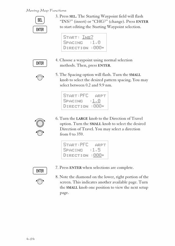
3. Press SEL. The Starting Waypoint field will flash
“INS?” (insert) or “CHG?” (change). Press ENTER
to start editing the Starting Waypoint selection.
Start: Ins?
Spacing :1.0
Direction :000·
4. Choose a waypoint using normal selection
methods. Then, press ENTER.
5. The Spacing option will flash. Turn the SMALL
knob to select the desired pattern spacing. You may
select between 0.2 and 9.9 nm.
Start:PFC arpt
Spacing :1.0
Direction :000·
6. Turn the LARGE knob to the Direction of Travel
option. Turn the SMALL knob to select the desired
Direction of Travel. You may select a direction
from 0 to 359.
Start:PFC arpt
Spacing :1.5
Direction :000·
7. Press ENTER when selections are complete.
8. Note the diamond on the lower, right portion of the
screen. This indicates another available page. Turn
the SMALL knob one position to view the next setup
page.
4-24
Moving Map Functions
ENTER
ENTER
ENTER
SEL
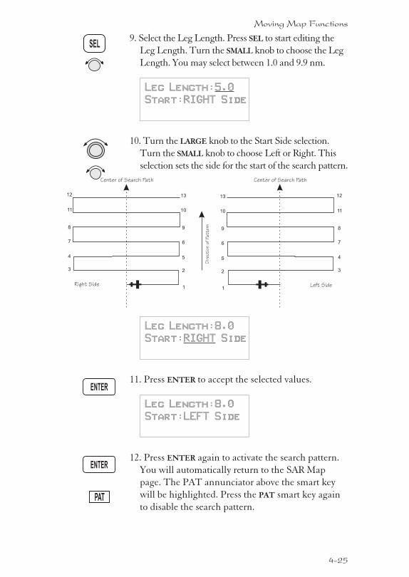
9. Select the Leg Length. Press SEL to start editing the
Leg Length. Turn the SMALL knob to choose the Leg
Length. You may select between 1.0 and 9.9 nm.
Leg Length:5.0
Start:RIGHT Side
10. Turn the LARGE knob to the Start Side selection.
Turn the SMALL knob to choose Left or Right. This
selection sets the side for the start of the search pattern.
Leg Length:8.0
Start:RIGHT Side
11. Press ENTER to accept the selected values.
Leg Length:8.0
Start:LEFT Side
12. Press ENTER again to activate the search pattern.
You will automatically return to the SAR Map
page. The PAT annunciator above the smart key
will be highlighted. Press the PAT smart key again
to disable the search pattern.
4-25
Moving Map Functions
ENTER
SEL
ENTER
PAT
1
2
5
6
9
10
13
3
4
7
8
11
12
Right Side Left Side1
2
5
6
9
10
13
3
4
7
8
11
12
Dir
ectio
nof
Pattern
Center of Search Path Center of Search Path
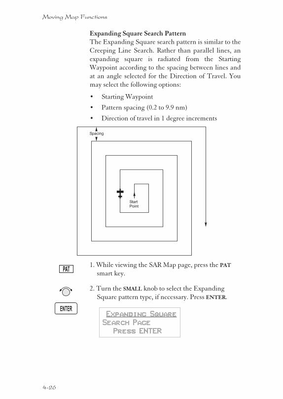
Expanding Square Search PatternThe Expanding Square search pattern is similar to the
Creeping Line Search. Rather than parallel lines, an
expanding square is radiated from the Starting
Waypoint according to the spacing between lines and
at an angle selected for the Direction of Travel. You
may select the following options:
� Starting Waypoint
� Pattern spacing (0.2 to 9.9 nm)
� Direction of travel in 1 degree increments
1. While viewing the SAR Map page, press the PAT
smart key.
2. Turn the SMALL knob to select the Expanding
Square pattern type, if necessary. Press ENTER.
Expanding Square
Search Page
Press ENTER
4-26
Moving Map Functions
ENTER
PAT
Spacing
StartPoint
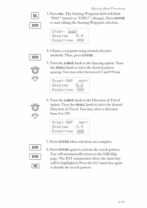
3. Press SEL. The Starting Waypoint field will flash
“INS?” (insert) or “CHG?” (change). Press ENTER
to start editing the Starting Waypoint selection.
Start: Ins?
Spacing :5.0
Direction :000
4. Choose a waypoint using normal selection
methods. Then, press ENTER.
5. Turn the LARGE knob to the Spacing option. Turn
the SMALL knob to select the desired pattern
spacing. You may select between 0.2 and 9.9 nm.
Start:ONP arpt
Spacing :5.0
Direction :000
6. Turn the LARGE knob to the Direction of Travel
option. Turn the SMALL knob to select the desired
Direction of Travel. You may select a direction
from 0 to 359.
Start:ONP arpt
Spacing :3.5
Direction :000
7. Press ENTER when selections are complete.
8. Press ENTER again to activate the search pattern.
You will automatically return to the SAR Map
page. The PAT annunciator above the smart key
will be highlighted. Press the PAT smart key again
to disable the search pattern.
4-27
Moving Map Functions
ENTER
SEL
PAT
ENTER
ENTER
ENTER
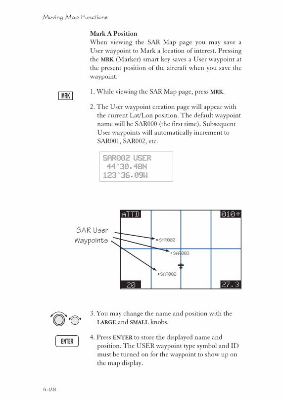
Mark A PositionWhen viewing the SAR Map page you may save a
User waypoint to Mark a location of interest. Pressing
the MRK (Marker) smart key saves a User waypoint at
the present position of the aircraft when you save the
waypoint.
1. While viewing the SAR Map page, press MRK.
2. The User waypoint creation page will appear with
the current Lat/Lon position. The default waypoint
name will be SAR000 (the first time). Subsequent
User waypoints will automatically increment to
SAR001, SAR002, etc.
SAR002 USER
44°30.48N
123°36.09W
3. You may change the name and position with the
LARGE and SMALL knobs.
4. Press ENTER to store the displayed name and
position. The USER waypoint type symbol and ID
must be turned on for the waypoint to show up on
the map display.
4-28
Moving Map Functions
ENTER
MRK
20 27.3
010TTaTTD
SAR003
SAR000
SAR002
SAR User
Waypoints
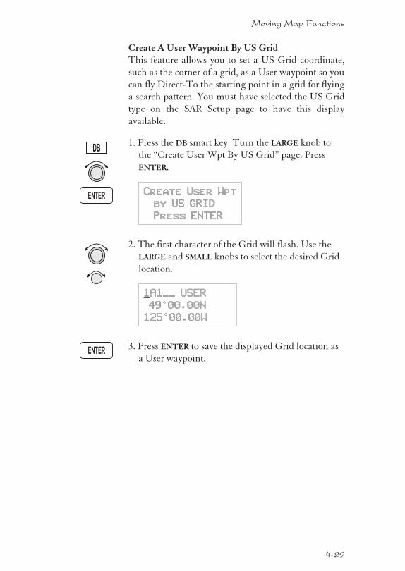
Create A User Waypoint By US GridThis feature allows you to set a US Grid coordinate,
such as the corner of a grid, as a User waypoint so you
can fly Direct-To the starting point in a grid for flying
a search pattern. You must have selected the US Grid
type on the SAR Setup page to have this display
available.
1. Press the DB smart key. Turn the LARGE knob to
the “Create User Wpt By US Grid” page. Press
ENTER.
Create User Wpt
by US GRID
Press ENTER
2. The first character of the Grid will flash. Use the
LARGE and SMALL knobs to select the desired Grid
location.
1A1__ USER
49°00.00N
125°00.00W
3. Press ENTER to save the displayed Grid location as
a User waypoint.
4-29
Moving Map Functions
DB
ENTER
ENTER
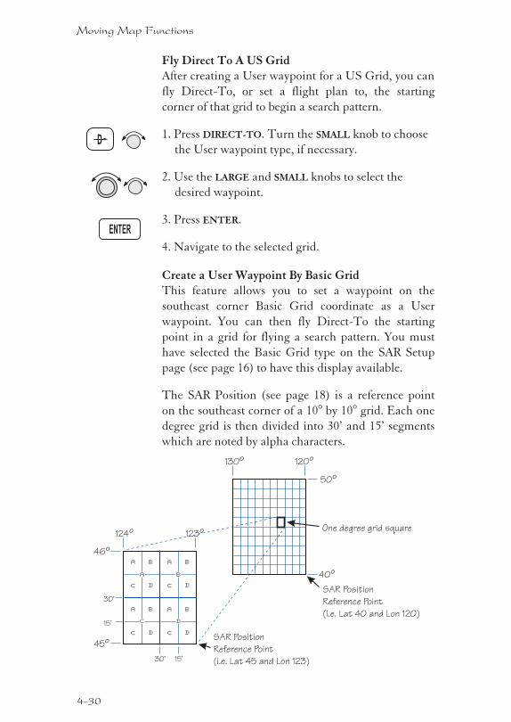
Fly Direct To A US GridAfter creating a User waypoint for a US Grid, you can
fly Direct-To, or set a flight plan to, the starting
corner of that grid to begin a search pattern.
1. Press DIRECT-TO. Turn the SMALL knob to choose
the User waypoint type, if necessary.
2. Use the LARGE and SMALL knobs to select the
desired waypoint.
3. Press ENTER.
4. Navigate to the selected grid.
Create a User Waypoint By Basic GridThis feature allows you to set a waypoint on the
southeast corner Basic Grid coordinate as a User
waypoint. You can then fly Direct-To the starting
point in a grid for flying a search pattern. You must
have selected the Basic Grid type on the SAR Setup
page (see page 16) to have this display available.
The SAR Position (see page 18) is a reference point
on the southeast corner of a 10° by 10° grid. Each one
degree grid is then divided into 30’ and 15’ segments
which are noted by alpha characters.
4-30
Moving Map Functions
ENTER
D
a b
c d
a b
c d
a b
c d
a b
c d
a b
c d
45º
46º
123º124º
SAR Position
Reference Point
(i.e. Lat 45 and Lon 123)30’ 15’
30’
15’
40º
50º
120º130º
SAR Position
Reference Point
(i.e. Lat 40 and Lon 120)
One degree grid square
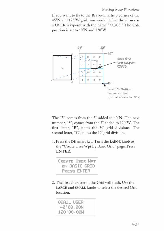
If you want to fly to the Bravo-Charlie 3 corner of the
45°N and 123°W grid, you would define the corner as
a USER waypoint with the name “53BC3.” The SAR
position is set to 40°N and 120°W.
The “5” comes from the 5° added to 40°N. The next
number, “3”, comes from the 3° added to 120°W. The
first letter, “B”, notes the 30’ grid divisions. The
second letter, “C”, notes the 15’ grid division.
1. Press the DB smart key. Turn the LARGE knob to
the “Create User Wpt By Basic Grid” page. Press
ENTER.
Create User Wpt
by BASIC GRID
Press ENTER
2. The first character of the Grid will flash. Use the
LARGE and SMALL knobs to select the desired Grid
location.
00A1_ USER
40°00.00N
120°00.00W
4-31
Moving Map Functions
a b
c d
a b
c d
a b
c d
a b
c d
a
c d
45º
46º
123º124º
New SAR Position
Reference Point
(i.e. Lat 45 and Lon 123)
1
C
2
43
Basic Grid
User Waypoint
53BC3
b
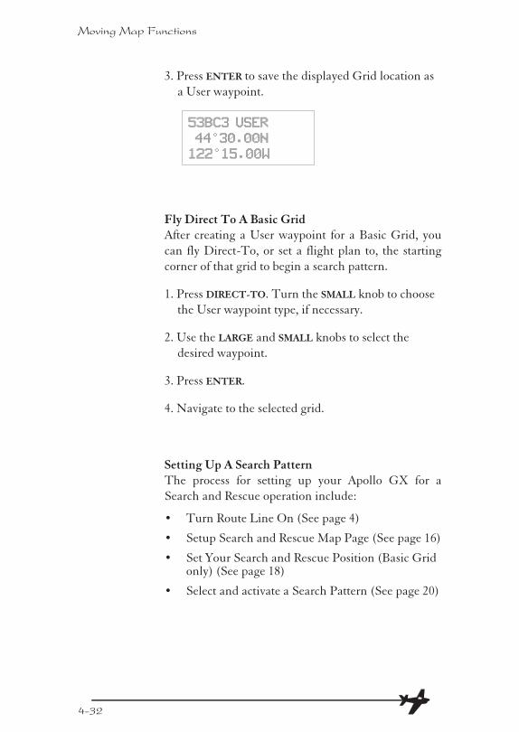
3. Press ENTER to save the displayed Grid location as
a User waypoint.
53BC3 USER
44°30.00N
122°15.00W
Fly Direct To A Basic GridAfter creating a User waypoint for a Basic Grid, you
can fly Direct-To, or set a flight plan to, the starting
corner of that grid to begin a search pattern.
1. Press DIRECT-TO. Turn the SMALL knob to choose
the User waypoint type, if necessary.
2. Use the LARGE and SMALL knobs to select the
desired waypoint.
3. Press ENTER.
4. Navigate to the selected grid.
Setting Up A Search PatternThe process for setting up your Apollo GX for a
Search and Rescue operation include:
� Turn Route Line On (See page 4)
� Setup Search and Rescue Map Page (See page 16)
� Set Your Search and Rescue Position (Basic Gridonly) (See page 18)
� Select and activate a Search Pattern (See page 20)
4-32
Moving Map Functions
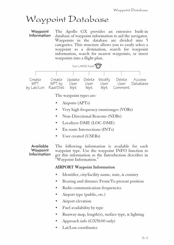
Waypoint DatabaseWaypoint
InformationThe Apollo GX provides an extensive built-indatabase of waypoint information to aid the navigator.Waypoints in the database are divided into 5categories. This structure allows you to easily select awaypoint as a destination, search for waypointinformation, search for nearest waypoints, or insertwaypoints into a flight plan.
The waypoint types are:
� Airports (APTs)
� Very high frequency omniranges (VORs)
� Non-Directional Beacons (NDBs)
� Localizer-DME (LOC-DME)
� En route Intersections (INTs)
� User created (USERs)
AvailableWaypoint
Information
The following information is available for eachwaypoint type. Use the waypoint INFO function toget this information as the Introduction describes in“Waypoint Information.”
AIRPORT Waypoint Information
� Identifier, city/facility name, state, & country
� Bearing and distance From/To present position
� Radio communication frequencies
� Airport type (public, etc.)
� Airport elevation
� Fuel availability by type
� Runway map, length(s), surface type, & lighting
� Approach info (GX50/60 only)
� Lat/Lon coordinates
Waypoint Database
5-1
CreateWPT
by Lat/Lon
Turn LARGE Knob
DeleteUserWpt
CreateWPT by
Rad/Dist
ModifyUserWpt
DeleteUser
Comment
AccessDatabase
UpdateUserWpt

� Sunrise/Sunset times
� Waypoint comment
VOR Waypoint Information
� Identifier, name, state, & country
� Radial and distance from the VOR
� Bearing and distance from present position
� Map
� Operating frequency
� Lat/Lon coordinates
� Sunrise/Sunset time
� Waypoint comment
NDB Waypoint Information
� Identifier, name, state, & country
� Bearing and distance from present position
� Map
� Operating frequency
� Lat/Lon coordinates
� Sunrise/Sunset time
� Waypoint comment
LOC-DME Waypoint Information
� Identifier, name, & country
� Bearing and distance from present position
� Map
� Lat/Lon coordinates
� Sunrise/sunset time
� Waypoint comment
INT Waypoint Information
� INT (K) - Continental USA Intersections
� INT (O) - Other Americas Intersections
� Name & country
� Bearing and distance from present position
� Map
5-2
Waypoint Database
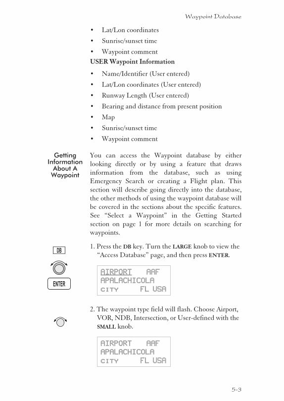
� Lat/Lon coordinates
� Sunrise/sunset time
� Waypoint comment
USER Waypoint Information
� Name/Identifier (User entered)
� Lat/Lon coordinates (User entered)
� Runway Length (User entered)
� Bearing and distance from present position
� Map
� Sunrise/sunset time
� Waypoint comment
GettingInformation
About AWaypoint
You can access the Waypoint database by either
looking directly or by using a feature that draws
information from the database, such as using
Emergency Search or creating a Flight plan. This
section will describe going directly into the database,
the other methods of using the waypoint database will
be covered in the sections about the specific features.
See “Select a Waypoint” in the Getting Started
section on page 1 for more details on searching for
waypoints.
1. Press the DB key. Turn the LARGE knob to view the
“Access Database” page, and then press ENTER.
AIRPORT AAF
APALACHICOLA
city FL USA
2. The waypoint type field will flash. Choose Airport,
VOR, NDB, Intersection, or User-defined with the
SMALL knob.
AIRPORT AAF
APALACHICOLA
city FL USA
5-3
Waypoint Database
ENTER
DB
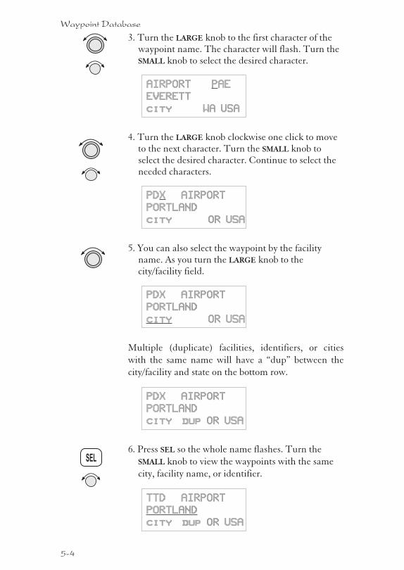
3. Turn the LARGE knob to the first character of thewaypoint name. The character will flash. Turn theSMALL knob to select the desired character.
AIRPORT PAE
EVERETT
city WA USA
4. Turn the LARGE knob clockwise one click to moveto the next character. Turn the SMALL knob toselect the desired character. Continue to select theneeded characters.
PDX AIRPORT
PORTLAND
city OR USA
5. You can also select the waypoint by the facilityname. As you turn the LARGE knob to thecity/facility field.
PDX AIRPORT
PORTLAND
city OR USA
Multiple (duplicate) facilities, identifiers, or cities
with the same name will have a “dup” between the
city/facility and state on the bottom row.
PDX AIRPORT
PORTLAND
city dup OR USA
6. Press SEL so the whole name flashes. Turn the
SMALL knob to view the waypoints with the same
city, facility name, or identifier.
TTD AIRPORT
PORTLAND
city dup OR USA
5-4
Waypoint Database
SEL
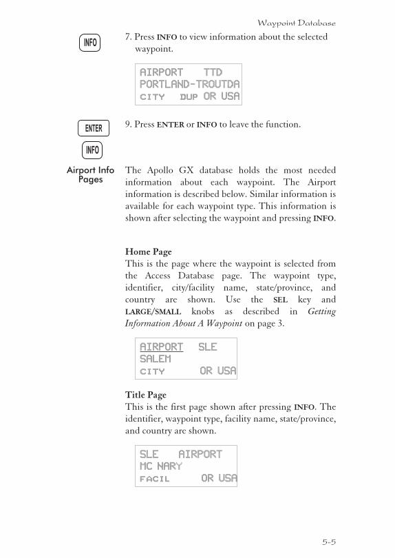
7. Press INFO to view information about the selected
waypoint.
AIRPORT TTD
PORTLAND-TROUTDA
city dup OR USA
9. Press ENTER or INFO to leave the function.
Airport InfoPages
The Apollo GX database holds the most needed
information about each waypoint. The Airport
information is described below. Similar information is
available for each waypoint type. This information is
shown after selecting the waypoint and pressing INFO.
Home PageThis is the page where the waypoint is selected from
the Access Database page. The waypoint type,
identifier, city/facility name, state/province, and
country are shown. Use the SEL key and
LARGE/SMALL knobs as described in Getting
Information About A Waypoint on page 3.
AIRPORT SLE
SALEM
city OR USA
Title PageThis is the first page shown after pressing INFO. The
identifier, waypoint type, facility name, state/province,
and country are shown.
SLE AIRPORT
MC NARY
facil OR USA
5-5
Waypoint Database
ENTER
INFO
INFO
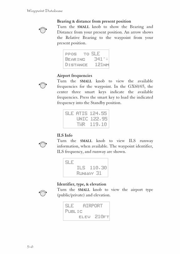
Bearing & distance from present positionTurn the SMALL knob to show the Bearing and
Distance from your present position. An arrow shows
the Relative Bearing to the waypoint from your
present position.
ppos to SLE
Bearing 341°²
Distance 121nm
Airport frequenciesTurn the SMALL knob to view the available
frequencies for the waypoint. In the GX60/65, the
center three smart keys indicate the available
frequencies. Press the smart key to load the indicated
frequency into the Standby position.
SLE ATIS 124.55
UNIC 122.95
TWR 119.10
ILS InfoTurn the SMALL knob to view ILS runway
information, when available. The waypoint identifier,
ILS frequency, and runway are shown.
SLE
ILS 110.30
Runway 31
Identifier, type, & elevationTurn the SMALL knob to view the airport type
(public/private) and elevation.
SLE AIRPORT
Public
elev 210ft
5-6
Waypoint Database
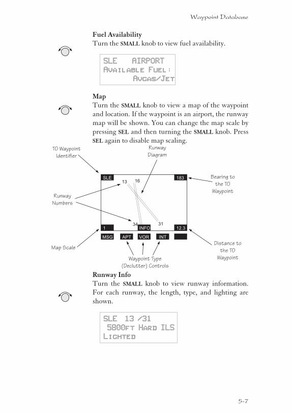
Fuel AvailabilityTurn the SMALL knob to view fuel availability.
SLE AIRPORT
Available Fuel:
Avgas/Jet
MapTurn the SMALL knob to view a map of the waypoint
and location. If the waypoint is an airport, the runway
map will be shown. You can change the map scale by
pressing SEL and then turning the SMALL knob. Press
SEL again to disable map scaling.
Runway InfoTurn the SMALL knob to view runway information.
For each runway, the length, type, and lighting are
shown.
SLE 13 /31
5800ft Hard ILS
Lighted
5-7
Waypoint Database
TO Waypoint
Identifier
Map Scale
Runway
Diagram
Bearing to
the TO
Waypoint
Distance to
the TO
Waypoint
Runway
Numbers
SLE
1
183
12.3
13 16
34 31INFO
MSG APT VOR INT
Waypoint Type
(Declutter) Controls
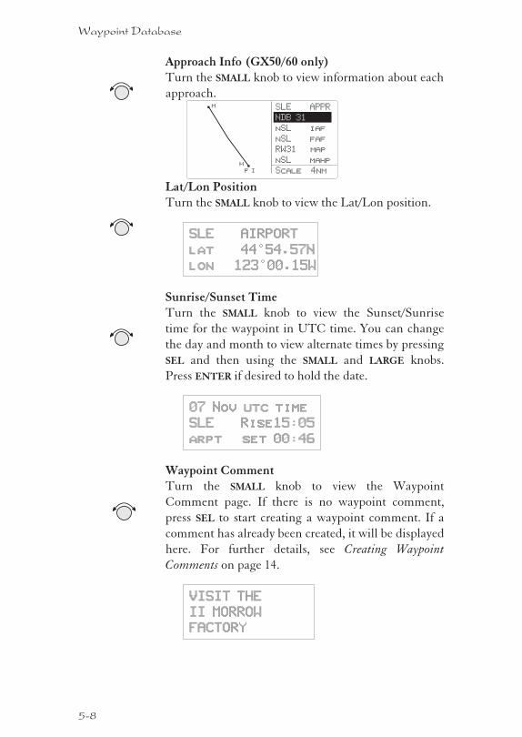
Approach Info (GX50/60 only)Turn the SMALL knob to view information about each
approach.
Lat/Lon PositionTurn the SMALL knob to view the Lat/Lon position.
SLE AIRPORT
lat 44°54.57N
lon 123°00.15W
Sunrise/Sunset TimeTurn the SMALL knob to view the Sunset/Sunrise
time for the waypoint in UTC time. You can change
the day and month to view alternate times by pressing
SEL and then using the SMALL and LARGE knobs.
Press ENTER if desired to hold the date.
07 Nov utc time
SLE Rise15:05
arpt set 00:46
Waypoint CommentTurn the SMALL knob to view the Waypoint
Comment page. If there is no waypoint comment,
press SEL to start creating a waypoint comment. If a
comment has already been created, it will be displayed
here. For further details, see Creating Waypoint
Comments on page 14.
VISIT THE
II MORROW
FACTORY
5-8
Waypoint Database
SLE APPR
nSL iaf
nSL faf
RW31 map
nSL mahp
Scale 4nmh
m
f i
NDB 31
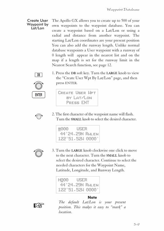
Create UserWaypoint by
Lat/Lon
The Apollo GX allows you to create up to 500 of your
own waypoints to the waypoint database. You can
create a waypoint based on a Lat/Lon or using a
radial and distance from another waypoint. The
starting Lat/Lon coordinates are your present position
You can also add the runway length. Unlike normal
database waypoints a User waypoint with a runway of
0 length will appear in the nearest list and on the
map if a length is set for the runway limit in the
Nearest Search function, see page 12.
1. Press the DB soft key. Turn the LARGE knob to view
the “Create User Wpt By Lat/Lon” page, and then
press ENTER.
Create User Wpt
by Lat/Lon
Press ENT
2. The first character of the waypoint name will flash.
Turn the SMALL knob to select the desired character.
#000 USER
44°24.29N Rwlen
122°51.52W 0000’
3. Turn the LARGE knob clockwise one click to move
to the next character. Turn the SMALL knob to
select the desired character. Continue to select the
needed characters for the Waypoint Name,
Latitude, Longitude, and Runway Length.
H000 USER
44°24.29N Rwlen
122°51.52W 0000’
Note
The default Lat/Lon is your present
position. This makes it easy to “mark” a
location.
5-9
Waypoint Database
DB
ENTER
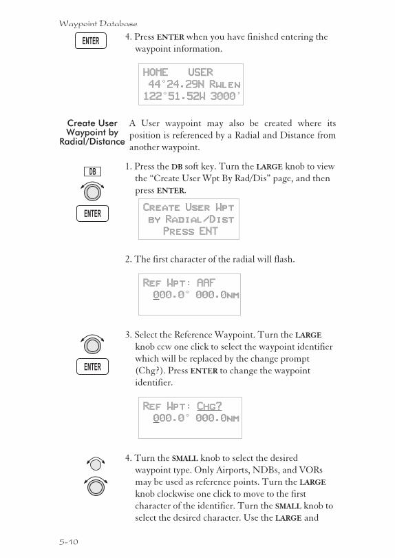
4. Press ENTER when you have finished entering the
waypoint information.
HOME USER
44°24.29N Rwlen
122°51.52W 3000’
Create UserWaypoint by
Radial/Distance
A User waypoint may also be created where its
position is referenced by a Radial and Distance from
another waypoint.
1. Press the DB soft key. Turn the LARGE knob to view
the “Create User Wpt By Rad/Dis” page, and then
press ENTER.
Create User Wpt
by Radial/Dist
Press ENT
2. The first character of the radial will flash.
Ref Wpt: AAF
000.0° 000.0nm
3. Select the Reference Waypoint. Turn the LARGE
knob ccw one click to select the waypoint identifier
which will be replaced by the change prompt
(Chg?). Press ENTER to change the waypoint
identifier.
Ref Wpt: Chg?
000.0° 000.0nm
4. Turn the SMALL knob to select the desired
waypoint type. Only Airports, NDBs, and VORs
may be used as reference points. Turn the LARGE
knob clockwise one click to move to the first
character of the identifier. Turn the SMALL knob to
select the desired character. Use the LARGE and
5-10
Waypoint Database
ENTER
ENTER
DB
ENTER
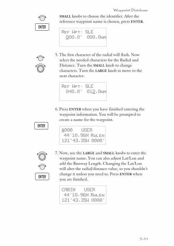
SMALL knobs to choose the identifier. After the
reference waypoint name is chosen, press ENTER.
Ref Wpt: SLE
000.0° 000.0nm
5. The first character of the radial will flash. Now
select the needed characters for the Radial and
Distance. Turn the SMALL knob to change
characters. Turn the LARGE knob to move to the
next character.
Ref Wpt: SLE
040.0° 012.0nm
6. Press ENTER when you have finished entering the
waypoint information. You will be prompted to
create a name for the waypoint.
#000 USER
44°10.96N Rwlen
121°43.35W 0000’
7. Now, use the LARGE and SMALL knobs to enter the
waypoint name. You can also adjust Lat/Lon and
add the Runway Length. Changing the Lat/Lon
will alter the radial/distance value, so you shouldn’t
change it unless you need to. Press ENTER when
you are finished.
CABIN USER
44°10.96N Rwlen
121°43.35W 0000’
5-11
Waypoint Database
ENTER
ENTER
ENTER
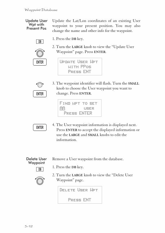
Update UserWpt with
Present Pos
Update the Lat/Lon coordinates of an existing User
waypoint to your present position. You may also
change the name and other info for the waypoint.
1. Press the DB key.
2. Turn the LARGE knob to view the “Update User
Waypoint” page. Press ENTER.
Update User Wpt
with PPos
Press ENT
3. The waypoint identifier will flash. Turn the SMALL
knob to choose the User waypoint you want to
change. Press ENTER.
Find wpt to set
AA user
Press ENTER
4. The User waypoint information is displayed next.
Press ENTER to accept the displayed information or
use the LARGE and SMALL knobs to edit the
information.
Delete UserWaypoint
Remove a User waypoint from the database.
1. Press the DB key.
2. Turn the LARGE knob to view the “Delete User
Waypoint” page.
Delete User Wpt
Press ENT
5-12
Waypoint Database
DB
DB
ENTER
ENTER
ENTER
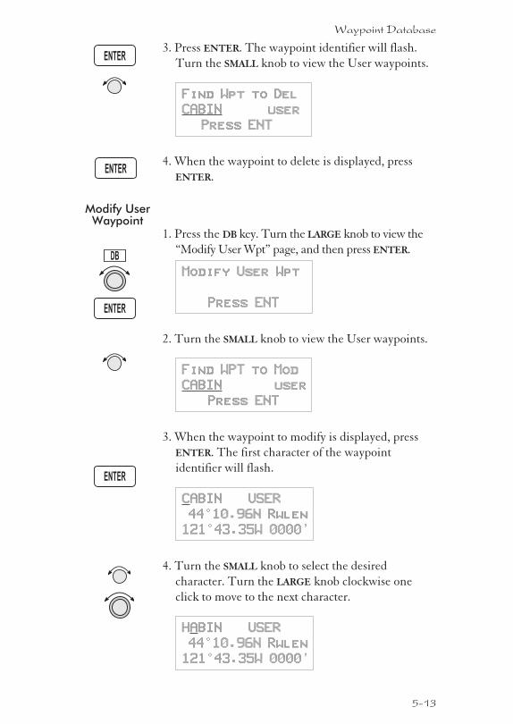
3. Press ENTER. The waypoint identifier will flash.
Turn the SMALL knob to view the User waypoints.
Find Wpt to Del
CABIN user
Press ENT
4. When the waypoint to delete is displayed, press
ENTER.
Modify UserWaypoint
1. Press the DB key. Turn the LARGE knob to view the
“Modify User Wpt” page, and then press ENTER.
Modify User Wpt
Press ENT
2. Turn the SMALL knob to view the User waypoints.
Find WPT to Mod
CABIN user
Press ENT
3. When the waypoint to modify is displayed, press
ENTER. The first character of the waypoint
identifier will flash.
CABIN USER
44°10.96N Rwlen
121°43.35W 0000’
4. Turn the SMALL knob to select the desired
character. Turn the LARGE knob clockwise one
click to move to the next character.
HABIN USER
44°10.96N Rwlen
121°43.35W 0000’
5-13
Waypoint Database
ENTER
ENTER
ENTER
DB
ENTER
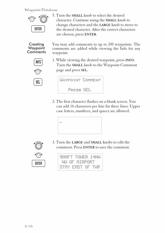
5. Turn the SMALL knob to select the desiredcharacter. Continue using the SMALL knob tochange characters and the LARGE knob to move tothe desired character. After the correct charactersare chosen, press ENTER.
CreatingWaypoint
Comments
You may add comments to up to 200 waypoints. Thecomments are added while viewing the Info for anywaypoint.
1. While viewing the desired waypoint, press INFO.
Turn the SMALL knob to the Waypoint Comment
page and press SEL.
Waypoint Comment
Press SEL
2. The first character flashes on a blank screen. Youcan add 16 characters per line for three lines. Uppercase letters, numbers, and spaces are allowed.
3. Turn the LARGE and SMALL knobs to edit the
comment. Press ENTER to save the comment.
900FT TOWER 14NW
NW OF AIRPORT
STAY EAST OF TWR
5-14
Waypoint Database
ENTER
ENTER
INFO
SEL
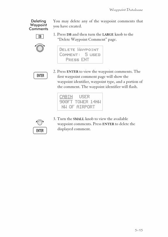
DeletingWaypoint
Comments
You may delete any of the waypoint comments that
you have created.
1. Press DB and then turn the LARGE knob to the
“Delete Waypoint Comment” page.
Delete Waypoint
Comment: 5 used
Press ENT
2. Press ENTER to view the waypoint comments. The
first waypoint comment page will show the
waypoint identifier, waypoint type, and a portion of
the comment. The waypoint identifier will flash.
CABIN USER
900FT TOWER 14NW
NW OF AIRPORT
3. Turn the SMALL knob to view the available
waypoint comments. Press ENTER to delete the
displayed comment.
5-15
Waypoint Database
ENTER
ENTER
DB
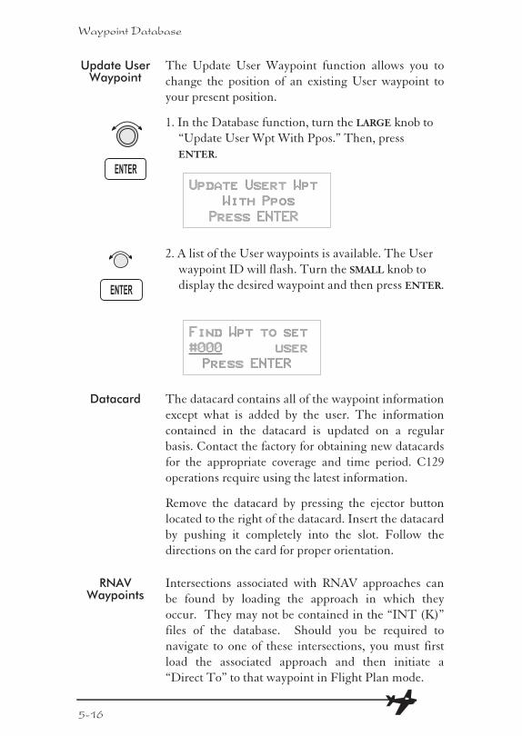
Update UserWaypoint
The Update User Waypoint function allows you to
change the position of an existing User waypoint to
your present position.
1. In the Database function, turn the LARGE knob to
“Update User Wpt With Ppos.” Then, press
ENTER.
Update Usert Wpt
With Ppos
Press ENTER
2. A list of the User waypoints is available. The User
waypoint ID will flash. Turn the SMALL knob to
display the desired waypoint and then press ENTER.
Find Wpt to set
#000 user
Press ENTER
Datacard The datacard contains all of the waypoint information
except what is added by the user. The information
contained in the datacard is updated on a regular
basis. Contact the factory for obtaining new datacards
for the appropriate coverage and time period. C129
operations require using the latest information.
Remove the datacard by pressing the ejector button
located to the right of the datacard. Insert the datacard
by pushing it completely into the slot. Follow the
directions on the card for proper orientation.
RNAVWaypoints
Intersections associated with RNAV approaches can
be found by loading the approach in which they
occur. They may not be contained in the “INT (K)”
files of the database. Should you be required to
navigate to one of these intersections, you must first
load the associated approach and then initiate a
“Direct To” to that waypoint in Flight Plan mode.
5-16
Waypoint Database
ENTER
ENTER
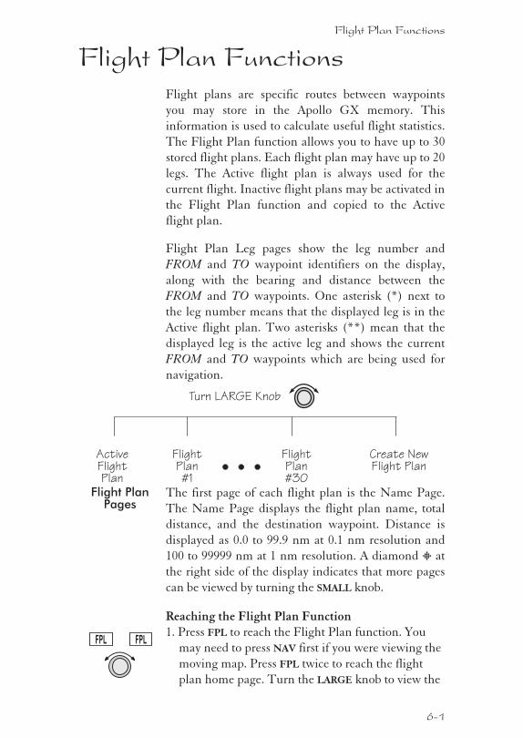
Flight Plan FunctionsFlight plans are specific routes between waypoints
you may store in the Apollo GX memory. This
information is used to calculate useful flight statistics.
The Flight Plan function allows you to have up to 30
stored flight plans. Each flight plan may have up to 20
legs. The Active flight plan is always used for the
current flight. Inactive flight plans may be activated in
the Flight Plan function and copied to the Active
flight plan.
Flight Plan Leg pages show the leg number and
FROM and TO waypoint identifiers on the display,
along with the bearing and distance between the
FROM and TO waypoints. One asterisk (*) next to
the leg number means that the displayed leg is in the
Active flight plan. Two asterisks (**) mean that the
displayed leg is the active leg and shows the current
FROM and TO waypoints which are being used for
navigation.
Flight PlanPages
The first page of each flight plan is the Name Page.
The Name Page displays the flight plan name, total
distance, and the destination waypoint. Distance is
displayed as 0.0 to 99.9 nm at 0.1 nm resolution and
100 to 99999 nm at 1 nm resolution. A diamond Y at
the right side of the display indicates that more pages
can be viewed by turning the SMALL knob.
Reaching the Flight Plan Function1. Press FPL to reach the Flight Plan function. You
may need to press NAV first if you were viewing the
moving map. Press FPL twice to reach the flight
plan home page. Turn the LARGE knob to view the
Flight Plan Functions
6-1
FPL FPL
ActiveFlightPlan
FlightPlan#1
Turn LARGE Knob
Create NewFlight Plan
FlightPlan#30
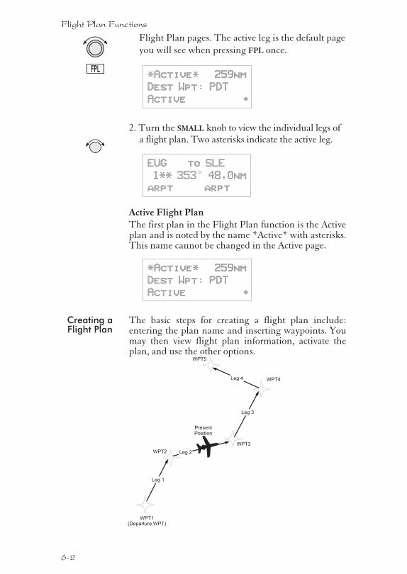
Flight Plan pages. The active leg is the default page
you will see when pressing FPL once.
*Active* 259nm
Dest Wpt: PDT
Active ·
2. Turn the SMALL knob to view the individual legs ofa flight plan. Two asterisks indicate the active leg.
EUG to SLE
1** 353° 48.0nm
arpt arpt
Active Flight PlanThe first plan in the Flight Plan function is the Activeplan and is noted by the name *Active* with asterisks.This name cannot be changed in the Active page.
*Active* 259nm
Dest Wpt: PDT
Active ·
Creating aFlight Plan
The basic steps for creating a flight plan include:entering the plan name and inserting waypoints. Youmay then view flight plan information, activate theplan, and use the other options.
6-2
Flight Plan Functions
FPL
WPT2
WPT1(Departure WPT)
PresentPosition
WPT3
WPT4
WPT5
Leg 1
Leg 2
Leg 3
Leg 4
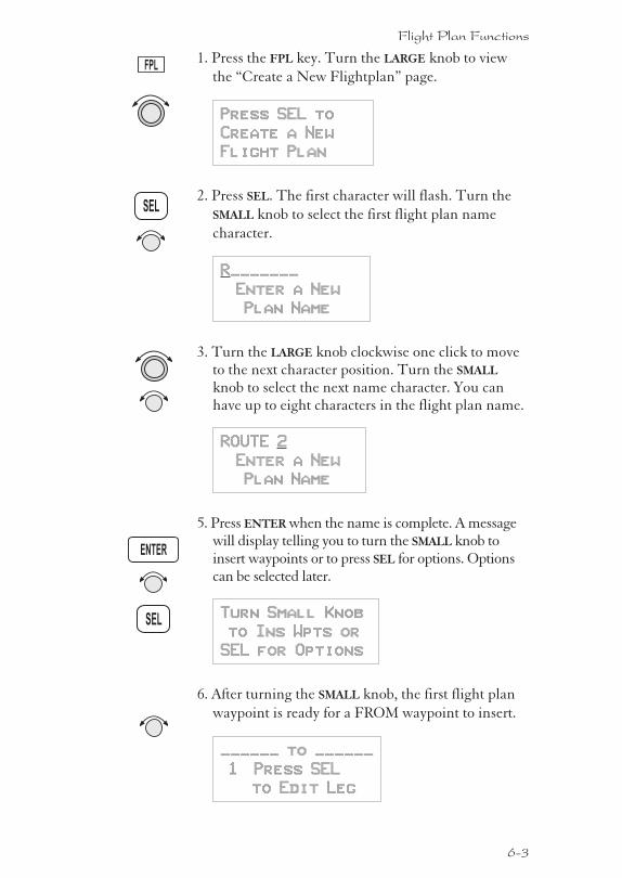
1. Press the FPL key. Turn the LARGE knob to view
the “Create a New Flightplan” page.
Press SEL to
Create a New
Flight Plan
2. Press SEL. The first character will flash. Turn the
SMALL knob to select the first flight plan name
character.
R_______
Enter a New
Plan Name
3. Turn the LARGE knob clockwise one click to moveto the next character position. Turn the SMALL
knob to select the next name character. You canhave up to eight characters in the flight plan name.
ROUTE 2
Enter a New
Plan Name
5. Press ENTER when the name is complete. A messagewill display telling you to turn the SMALL knob toinsert waypoints or to press SEL for options. Optionscan be selected later.
Turn Small Knob
to Ins Wpts or
SEL for Options
6. After turning the SMALL knob, the first flight plan
waypoint is ready for a FROM waypoint to insert.
______ to ______
1 Press SEL
to Edit Leg
6-3
Flight Plan Functions
SEL
FPL
SEL
ENTER
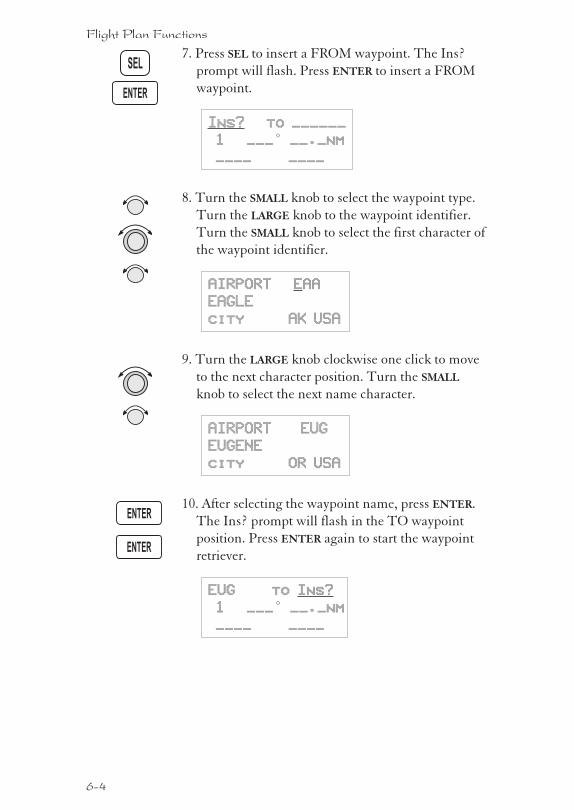
7. Press SEL to insert a FROM waypoint. The Ins?
prompt will flash. Press ENTER to insert a FROM
waypoint.
Ins? to ______
1 ___° __._nm
____ ____
8. Turn the SMALL knob to select the waypoint type.
Turn the LARGE knob to the waypoint identifier.
Turn the SMALL knob to select the first character of
the waypoint identifier.
AIRPORT EAA
EAGLE
city AK USA
9. Turn the LARGE knob clockwise one click to move
to the next character position. Turn the SMALL
knob to select the next name character.
AIRPORT EUG
EUGENE
city OR USA
10. After selecting the waypoint name, press ENTER.
The Ins? prompt will flash in the TO waypoint
position. Press ENTER again to start the waypoint
retriever.
EUG to Ins?
1 ___° __._nm
____ ____
6-4
Flight Plan Functions
SEL
ENTER
ENTER
ENTER
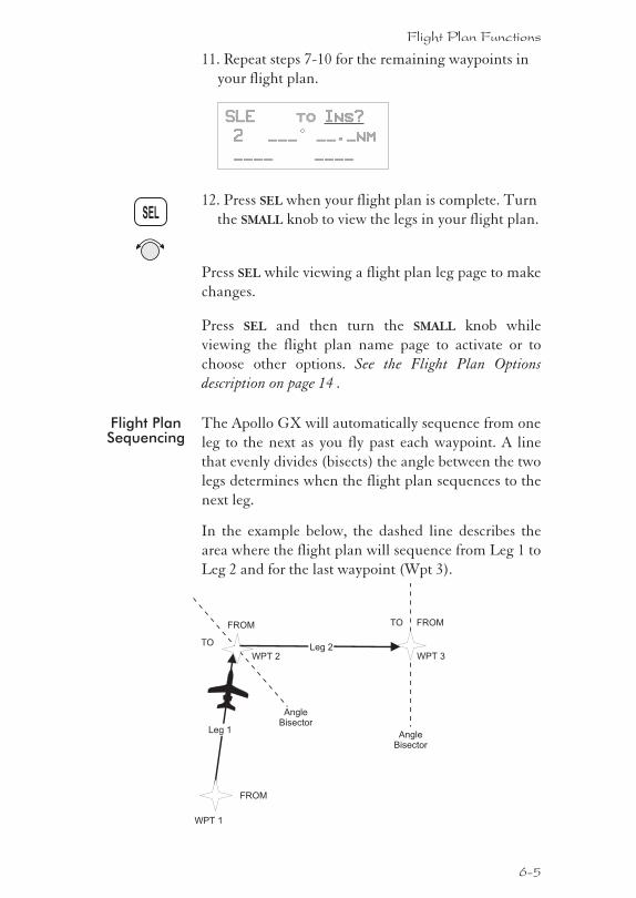
11. Repeat steps 7-10 for the remaining waypoints in
your flight plan.
SLE to Ins?
2 ___° __._nm
____ ____
12. Press SEL when your flight plan is complete. Turn
the SMALL knob to view the legs in your flight plan.
Press SEL while viewing a flight plan leg page to make
changes.
Press SEL and then turn the SMALL knob while
viewing the flight plan name page to activate or to
choose other options. See the Flight Plan Options
description on page 14 .
Flight PlanSequencing
The Apollo GX will automatically sequence from one
leg to the next as you fly past each waypoint. A line
that evenly divides (bisects) the angle between the two
legs determines when the flight plan sequences to the
next leg.
In the example below, the dashed line describes the
area where the flight plan will sequence from Leg 1 to
Leg 2 and for the last waypoint (Wpt 3).
6-5
Flight Plan Functions
SEL
WPT 2 WPT 3
Leg 1
Leg 2
WPT 1
FROM
FROM
TO
AngleBisector
AngleBisector
FROMTO
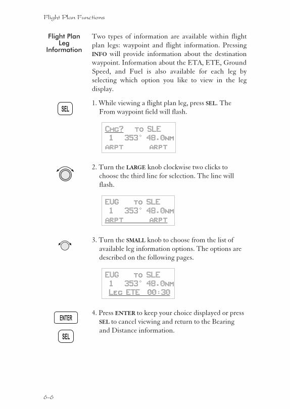
Flight PlanLeg
Information
Two types of information are available within flight
plan legs: waypoint and flight information. Pressing
INFO will provide information about the destination
waypoint. Information about the ETA, ETE, Ground
Speed, and Fuel is also available for each leg by
selecting which option you like to view in the leg
display.
1. While viewing a flight plan leg, press SEL. The
From waypoint field will flash.
Chg? to SLE
1 353° 48.0nm
arpt arpt
2. Turn the LARGE knob clockwise two clicks to
choose the third line for selection. The line will
flash.
EUG to SLE
1 353° 48.0nm
arpt arpt
3. Turn the SMALL knob to choose from the list of
available leg information options. The options are
described on the following pages.
EUG to SLE
1 353° 48.0nm
Leg ETE 00:30
4. Press ENTER to keep your choice displayed or press
SEL to cancel viewing and return to the Bearing
and Distance information.
6-6
Flight Plan Functions
SEL
SEL
ENTER
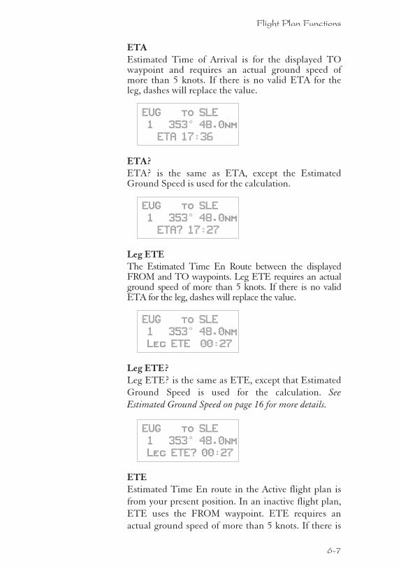
ETAEstimated Time of Arrival is for the displayed TOwaypoint and requires an actual ground speed ofmore than 5 knots. If there is no valid ETA for theleg, dashes will replace the value.
EUG to SLE
1 353° 48.0nm
ETA 17:36
ETA?ETA? is the same as ETA, except the EstimatedGround Speed is used for the calculation.
EUG to SLE
1 353° 48.0nm
ETA? 17:27
Leg ETEThe Estimated Time En Route between the displayedFROM and TO waypoints. Leg ETE requires an actualground speed of more than 5 knots. If there is no validETA for the leg, dashes will replace the value.
EUG to SLE
1 353° 48.0nm
Leg ETE 00:27
Leg ETE?Leg ETE? is the same as ETE, except that Estimated
Ground Speed is used for the calculation. See
Estimated Ground Speed on page 16 for more details.
EUG to SLE
1 353° 48.0nm
Leg ETE? 00:27
ETEEstimated Time En route in the Active flight plan is
from your present position. In an inactive flight plan,
ETE uses the FROM waypoint. ETE requires an
actual ground speed of more than 5 knots. If there is
6-7
Flight Plan Functions
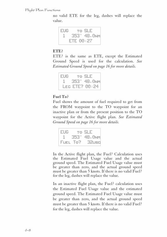
no valid ETE for the leg, dashes will replace the
value.
EUG to SLE
1 353° 48.0nm
ETE 00:27
ETE?ETE? is the same as ETE, except the Estimated
Ground Speed is used for the calculation. See
Estimated Ground Speed on page 16 for more details.
EUG to SLE
1 353° 48.0nm
Leg ETE? 00:24
Fuel To?Fuel shows the amount of fuel required to get from
the FROM waypoint to the TO waypoint for an
inactive plan or from the present position to the TO
waypoint for the Active flight plan. See Estimated
Ground Speed on page 16 for more details.
EUG to SLE
1 353° 48.0nm
Fuel To? 32usg
In the Active flight plan, the Fuel? Calculation usesthe Estimated Fuel Usage value and the actualground speed. The Estimated Fuel Usage value mustbe greater than zero, and the actual ground speedmust be greater than 5 knots. If there is no valid Fuel?for the leg, dashes will replace the value.
In an inactive flight plan, the Fuel? calculation uses
the Estimated Fuel Usage value and the estimated
ground speed. The Estimated Fuel Usage value must
be greater than zero, and the actual ground speed
must be greater than 5 knots. If there is no valid Fuel?
for the leg, dashes will replace the value.
6-8
Flight Plan Functions
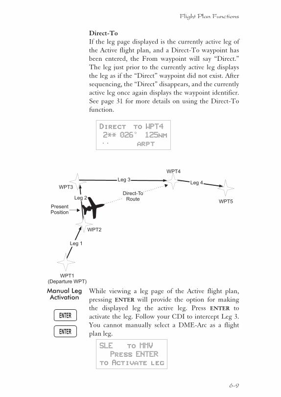
Direct-ToIf the leg page displayed is the currently active leg of
the Active flight plan, and a Direct-To waypoint has
been entered, the From waypoint will say “Direct.”
The leg just prior to the currently active leg displays
the leg as if the “Direct” waypoint did not exist. After
sequencing, the “Direct” disappears, and the currently
active leg once again displays the waypoint identifier.
See page 31 for more details on using the Direct-To
function.
Direct to WPT4
2** 026° 125nm
—— arpt
Manual LegActivation
While viewing a leg page of the Active flight plan,
pressing ENTER will provide the option for making
the displayed leg the active leg. Press ENTER to
activate the leg. Follow your CDI to intercept Leg 3.
You cannot manually select a DME-Arc as a flight
plan leg.
SLE to MMV
Press ENTER
to Activate leg
6-9
Flight Plan Functions
ENTER
ENTER
WPT2
WPT1(Departure WPT)
PresentPosition
WPT3
WPT4
WPT5
Leg 1
Leg 2
Leg 3Leg 4
Direct-ToRoute
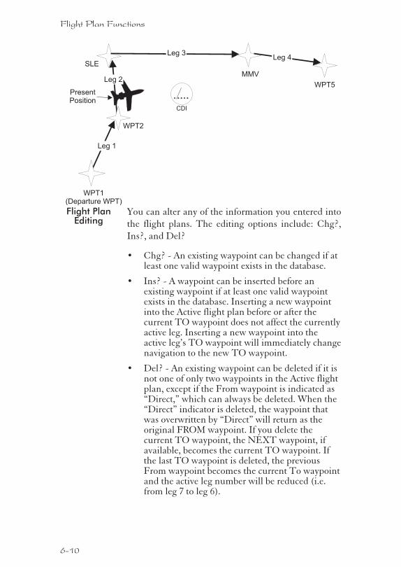
Flight PlanEditing
You can alter any of the information you entered into
the flight plans. The editing options include: Chg?,
Ins?, and Del?
� Chg? - An existing waypoint can be changed if atleast one valid waypoint exists in the database.
� Ins? - A waypoint can be inserted before anexisting waypoint if at least one valid waypointexists in the database. Inserting a new waypointinto the Active flight plan before or after thecurrent TO waypoint does not affect the currentlyactive leg. Inserting a new waypoint into theactive leg’s TO waypoint will immediately changenavigation to the new TO waypoint.
� Del? - An existing waypoint can be deleted if it isnot one of only two waypoints in the Active flightplan, except if the From waypoint is indicated as“Direct,” which can always be deleted. When the“Direct” indicator is deleted, the waypoint thatwas overwritten by “Direct” will return as theoriginal FROM waypoint. If you delete thecurrent TO waypoint, the NEXT waypoint, ifavailable, becomes the current TO waypoint. Ifthe last TO waypoint is deleted, the previousFrom waypoint becomes the current To waypointand the active leg number will be reduced (i.e.from leg 7 to leg 6).
6-10
Flight Plan Functions
WPT2
WPT1(Departure WPT)
PresentPosition
SLE
MMV
WPT5
Leg 1
Leg 2
Leg 3Leg 4
CDI
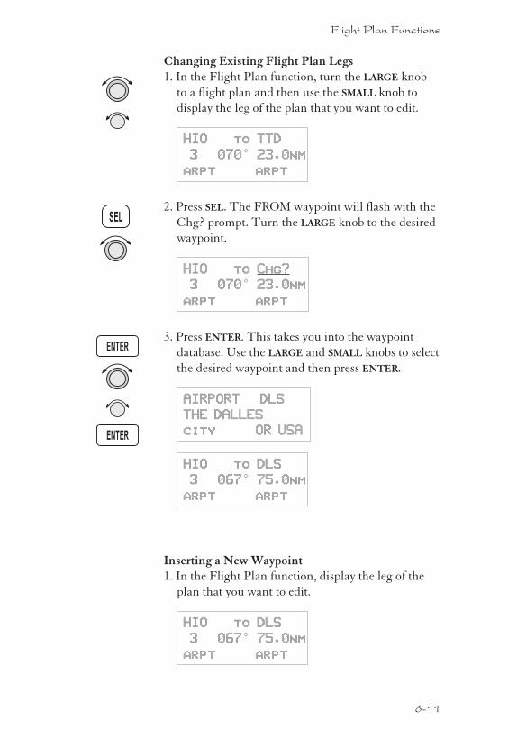
Changing Existing Flight Plan Legs1. In the Flight Plan function, turn the LARGE knob
to a flight plan and then use the SMALL knob to
display the leg of the plan that you want to edit.
HIO to TTD
3 070° 23.0nm
arpt arpt
2. Press SEL. The FROM waypoint will flash with the
Chg? prompt. Turn the LARGE knob to the desired
waypoint.
HIO to Chg?
3 070° 23.0nm
arpt arpt
3. Press ENTER. This takes you into the waypoint
database. Use the LARGE and SMALL knobs to select
the desired waypoint and then press ENTER.
AIRPORT DLS
THE DALLES
city OR USA
HIO to DLS
3 067° 75.0nm
arpt arpt
Inserting a New Waypoint1. In the Flight Plan function, display the leg of the
plan that you want to edit.
HIO to DLS
3 067° 75.0nm
arpt arpt
6-11
Flight Plan Functions
SEL
ENTER
ENTER
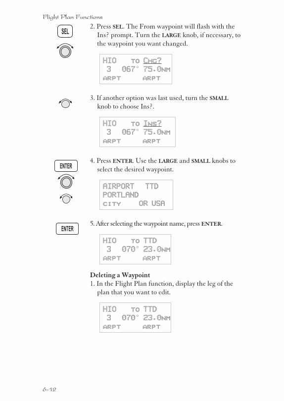
2. Press SEL. The From waypoint will flash with the
Ins? prompt. Turn the LARGE knob, if necessary, to
the waypoint you want changed.
HIO to Chg?
3 067° 75.0nm
arpt arpt
3. If another option was last used, turn the SMALL
knob to choose Ins?.
HIO to Ins?
3 067° 75.0nm
arpt arpt
4. Press ENTER. Use the LARGE and SMALL knobs to
select the desired waypoint.
AIRPORT TTD
PORTLAND
city OR USA
5. After selecting the waypoint name, press ENTER.
HIO to TTD
3 070° 23.0nm
arpt arpt
Deleting a Waypoint1. In the Flight Plan function, display the leg of the
plan that you want to edit.
HIO to TTD
3 070° 23.0nm
arpt arpt
6-12
Flight Plan Functions
ENTER
SEL
ENTER
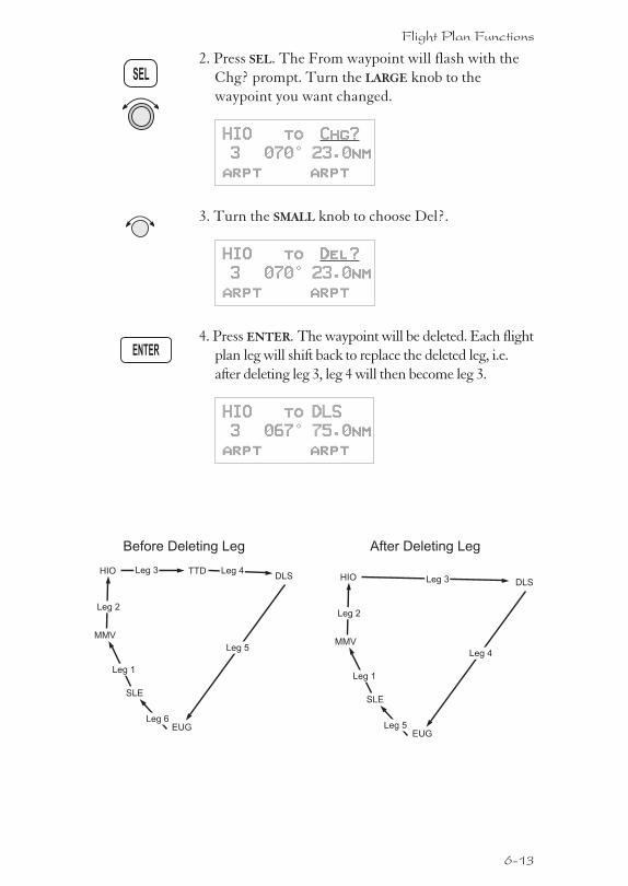
2. Press SEL. The From waypoint will flash with the
Chg? prompt. Turn the LARGE knob to the
waypoint you want changed.
HIO to Chg?
3 070° 23.0nm
arpt arpt
3. Turn the SMALL knob to choose Del?.
HIO to Del?
3 070° 23.0nm
arpt arpt
4. Press ENTER. The waypoint will be deleted. Each flight
plan leg will shift back to replace the deleted leg, i.e.
after deleting leg 3, leg 4 will then become leg 3.
HIO to DLS
3 067° 75.0nm
arpt arpt
6-13
Flight Plan Functions
SEL
ENTER
SLE
HIO
MMV
TTD
Leg 1
Leg 2
Leg 3 Leg 4DLS
EUG
Leg 5
Leg 6
SLE
HIO
MMV
Leg 1
Leg 2
Leg 3 DLS
EUGLeg 5
Before Deleting Leg After Deleting Leg
Leg 4
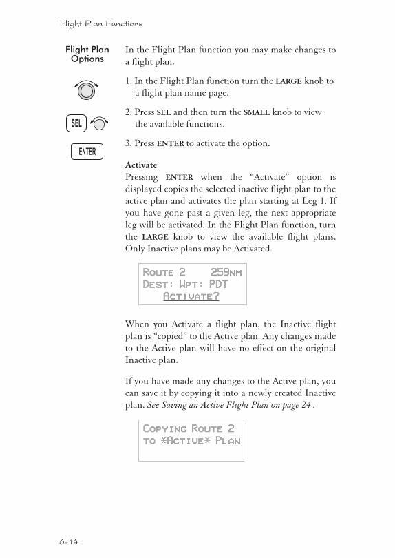
Flight PlanOptions
In the Flight Plan function you may make changes to
a flight plan.
1. In the Flight Plan function turn the LARGE knob to
a flight plan name page.
2. Press SEL and then turn the SMALL knob to view
the available functions.
3. Press ENTER to activate the option.
ActivatePressing ENTER when the “Activate” option is
displayed copies the selected inactive flight plan to the
active plan and activates the plan starting at Leg 1. If
you have gone past a given leg, the next appropriate
leg will be activated. In the Flight Plan function, turn
the LARGE knob to view the available flight plans.
Only Inactive plans may be Activated.
Route 2 259nm
Dest: Wpt: PDT
Activate?
When you Activate a flight plan, the Inactive flight
plan is “copied” to the Active plan. Any changes made
to the Active plan will have no effect on the original
Inactive plan.
If you have made any changes to the Active plan, you
can save it by copying it into a newly created Inactive
plan. See Saving an Active Flight Plan on page 24 .
Copying Route 2
to *Active* Plan
6-14
Flight Plan Functions
SEL
ENTER
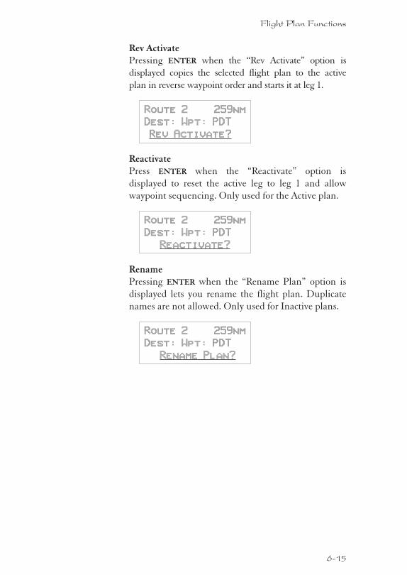
Rev ActivatePressing ENTER when the “Rev Activate” option is
displayed copies the selected flight plan to the active
plan in reverse waypoint order and starts it at leg 1.
Route 2 259nm
Dest: Wpt: PDT
Rev Activate?
ReactivatePress ENTER when the “Reactivate” option is
displayed to reset the active leg to leg 1 and allow
waypoint sequencing. Only used for the Active plan.
Route 2 259nm
Dest: Wpt: PDT
Reactivate?
RenamePressing ENTER when the “Rename Plan” option is
displayed lets you rename the flight plan. Duplicate
names are not allowed. Only used for Inactive plans.
Route 2 259nm
Dest: Wpt: PDT
Rename Plan?
6-15
Flight Plan Functions
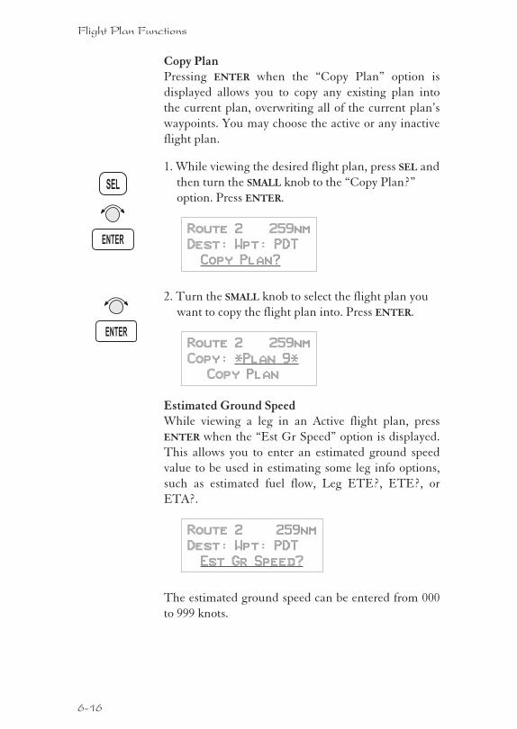
Copy PlanPressing ENTER when the “Copy Plan” option is
displayed allows you to copy any existing plan into
the current plan, overwriting all of the current plan’s
waypoints. You may choose the active or any inactive
flight plan.
1. While viewing the desired flight plan, press SEL and
then turn the SMALL knob to the “Copy Plan?”
option. Press ENTER.
Route 2 259nm
Dest: Wpt: PDT
Copy Plan?
2. Turn the SMALL knob to select the flight plan you
want to copy the flight plan into. Press ENTER.
Route 2 259nm
Copy: *Plan 9*
Copy Plan
Estimated Ground SpeedWhile viewing a leg in an Active flight plan, press
ENTER when the “Est Gr Speed” option is displayed.
This allows you to enter an estimated ground speed
value to be used in estimating some leg info options,
such as estimated fuel flow, Leg ETE?, ETE?, or
ETA?.
Route 2 259nm
Dest: Wpt: PDT
Est Gr Speed?
The estimated ground speed can be entered from 000
to 999 knots.
6-16
Flight Plan Functions
SEL
ENTER
ENTER
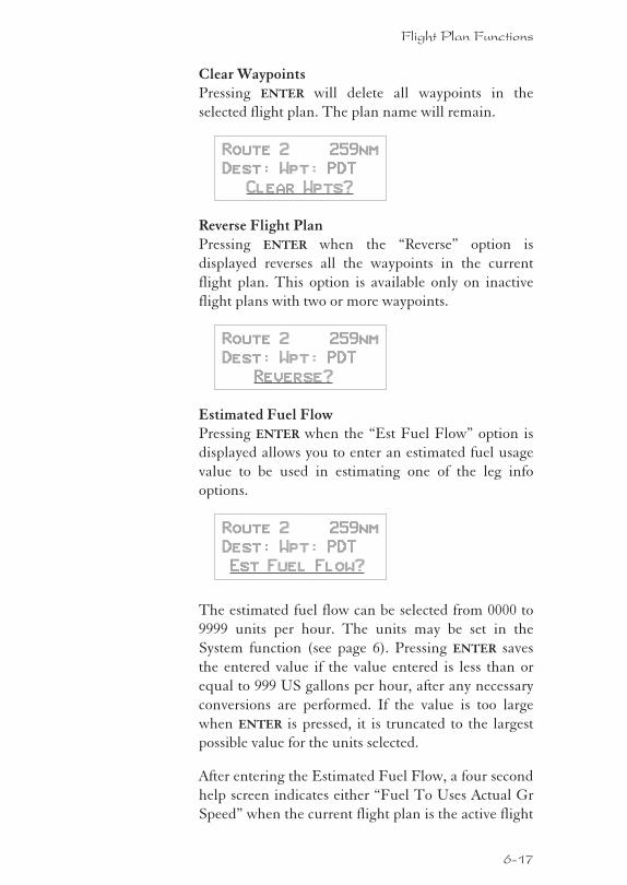
Clear WaypointsPressing ENTER will delete all waypoints in the
selected flight plan. The plan name will remain.
Route 2 259nm
Dest: Wpt: PDT
Clear Wpts?
Reverse Flight PlanPressing ENTER when the “Reverse” option is
displayed reverses all the waypoints in the current
flight plan. This option is available only on inactive
flight plans with two or more waypoints.
Route 2 259nm
Dest: Wpt: PDT
Reverse?
Estimated Fuel FlowPressing ENTER when the “Est Fuel Flow” option is
displayed allows you to enter an estimated fuel usage
value to be used in estimating one of the leg info
options.
Route 2 259nm
Dest: Wpt: PDT
Est Fuel Flow?
The estimated fuel flow can be selected from 0000 to
9999 units per hour. The units may be set in the
System function (see page 6). Pressing ENTER saves
the entered value if the value entered is less than or
equal to 999 US gallons per hour, after any necessary
conversions are performed. If the value is too large
when ENTER is pressed, it is truncated to the largest
possible value for the units selected.
After entering the Estimated Fuel Flow, a four second
help screen indicates either “Fuel To Uses Actual Gr
Speed” when the current flight plan is the active flight
6-17
Flight Plan Functions
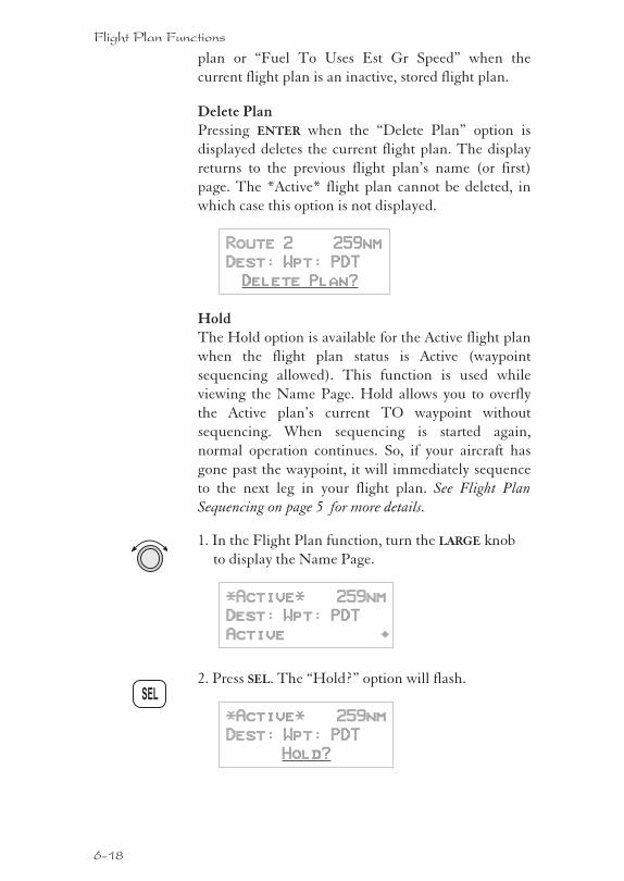
plan or “Fuel To Uses Est Gr Speed” when the
current flight plan is an inactive, stored flight plan.
Delete PlanPressing ENTER when the “Delete Plan” option is
displayed deletes the current flight plan. The display
returns to the previous flight plan’s name (or first)
page. The *Active* flight plan cannot be deleted, in
which case this option is not displayed.
Route 2 259nm
Dest: Wpt: PDT
Delete Plan?
HoldThe Hold option is available for the Active flight plan
when the flight plan status is Active (waypoint
sequencing allowed). This function is used while
viewing the Name Page. Hold allows you to overfly
the Active plan’s current TO waypoint without
sequencing. When sequencing is started again,
normal operation continues. So, if your aircraft has
gone past the waypoint, it will immediately sequence
to the next leg in your flight plan. See Flight Plan
Sequencing on page 5 for more details.
1. In the Flight Plan function, turn the LARGE knob
to display the Name Page.
*Active* 259nm
Dest: Wpt: PDT
Active ·
2. Press SEL. The “Hold?” option will flash.
*Active* 259nm
Dest: Wpt: PDT
Hold?
6-18
Flight Plan Functions
SEL
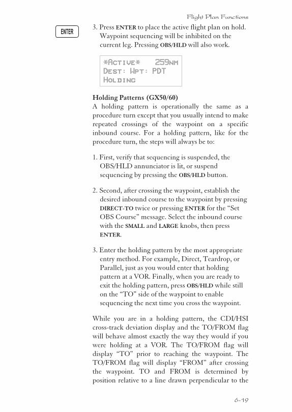
3. Press ENTER to place the active flight plan on hold.
Waypoint sequencing will be inhibited on the
current leg. Pressing OBS/HLD will also work.
*Active* 259nm
Dest: Wpt: PDT
Holding
Holding Patterns (GX50/60)A holding pattern is operationally the same as a
procedure turn except that you usually intend to make
repeated crossings of the waypoint on a specific
inbound course. For a holding pattern, like for the
procedure turn, the steps will always be to:
1. First, verify that sequencing is suspended, the
OBS/HLD annunciator is lit, or suspend
sequencing by pressing the OBS/HLD button.
2. Second, after crossing the waypoint, establish the
desired inbound course to the waypoint by pressing
DIRECT-TO twice or pressing ENTER for the “Set
OBS Course” message. Select the inbound course
with the SMALL and LARGE knobs, then press
ENTER.
3. Enter the holding pattern by the most appropriate
entry method. For example, Direct, Teardrop, or
Parallel, just as you would enter that holding
pattern at a VOR. Finally, when you are ready to
exit the holding pattern, press OBS/HLD while still
on the “TO” side of the waypoint to enable
sequencing the next time you cross the waypoint.
While you are in a holding pattern, the CDI/HSI
cross-track deviation display and the TO/FROM flag
will behave almost exactly the way they would if you
were holding at a VOR. The TO/FROM flag will
display “TO” prior to reaching the waypoint. The
TO/FROM flag will display “FROM” after crossing
the waypoint. TO and FROM is determined by
position relative to a line drawn perpendicular to the
6-19
Flight Plan Functions
ENTER
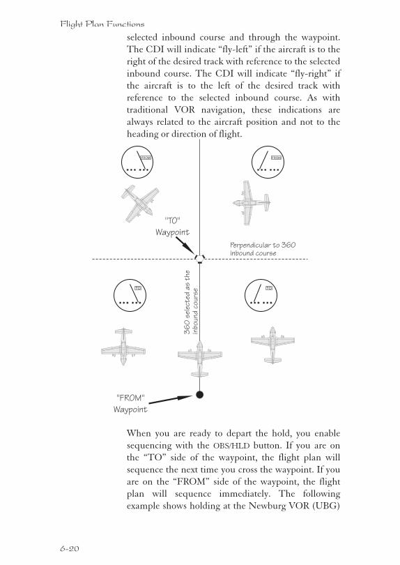
selected inbound course and through the waypoint.
The CDI will indicate “fly-left” if the aircraft is to the
right of the desired track with reference to the selected
inbound course. The CDI will indicate “fly-right” if
the aircraft is to the left of the desired track with
reference to the selected inbound course. As with
traditional VOR navigation, these indications are
always related to the aircraft position and not to the
heading or direction of flight.
When you are ready to depart the hold, you enable
sequencing with the OBS/HLD button. If you are on
the “TO” side of the waypoint, the flight plan will
sequence the next time you cross the waypoint. If you
are on the “FROM” side of the waypoint, the flight
plan will sequence immediately. The following
example shows holding at the Newburg VOR (UBG)
6-20
Flight Plan Functions
36
0sele
cted
as
the
inbound
cours
e
Perpendicular to 360inbound course
TO
FROM FROM
TO
"TO"
Waypoint
"FROM"
Waypoint
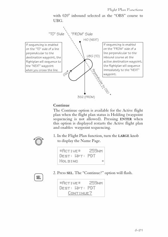
with 020° inbound selected as the “OBS” course to
UBG.
ContinueThe Continue option is available for the Active flightplan when the flight plan status is Holding (waypointsequencing is not allowed). Pressing ENTER whenthis option is displayed restarts the Active flight planand enables waypoint sequencing.
1. In the Flight Plan function, turn the LARGE knob
to display the Name Page.
*Active* 259nm
Dest: Wpt: PDT
Holding ·
2. Press SEL. The “Continue?” option will flash.
*Active* 259nm
Dest: Wpt: PDT
Continue?
6-21
Flight Plan Functions
SEL
HIO (NEXT)
UBG (TO)
3S2 (FROM)
Perpendicularto
020
020
"TO" Side "FROM" Side
If sequencing is enabled
on the "TO" side of a line
perpendicular to the
destination waypoint, the
flightplan will sequence to
the "NEXT" waypoint
when you cross the line.
If sequencing is enabled
on the "FROM" side of a
line perpendicular to the
inbound course at the
active destination waypoint,
the flightplan will sequence
immediately to the "NEXT"
waypoint.
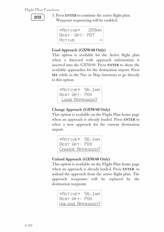
3. Press ENTER to continue the active flight plan.
Waypoint sequencing will be enabled.
*Active* 259nm
Dest: Wpt: PDT
Active ·
Load Approach (GX50/60 Only)This option is available for the Active flight plan
when a datacard with approach information is
inserted into the GX50/60. Press ENTER to show the
available approaches for the destination airport. Press
SEL while in the Nav or Map functions to go directly
to this option.
*Active* 56.1nm
Dest Wpt: PDX
Load Approach?
Change Approach (GX50/60 Only)This option is available on the Flight Plan home page
when an approach is already loaded. Press ENTER to
select a new approach for the current destination
airport.
*Active* 56.1nm
Dest Wpt: PDX
Change Approach?
Unload Approach (GX50/60 Only)This option is available on the Flight Plan home page
when an approach is already loaded. Press ENTER to
unload the approach from the active flight plan. The
approach waypoints will be replaced by the
destination waypoint.
*Active* 56.1nm
Dest Wpt: PDX
Unload Approach?
6-22
Flight Plan Functions
ENTER
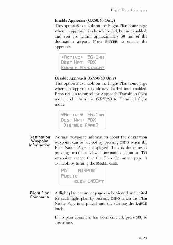
Enable Approach (GX50/60 Only)This option is available on the Flight Plan home page
when an approach is already loaded, but not enabled,
and you are within approximately 30 nm of the
destination airport. Press ENTER to enable the
approach.
*Active* 56.1nm
Dest Wpt: PDX
Enable Approach?
Disable Approach (GX50/60 Only)This option is available on the Flight Plan home page
when an approach is already loaded and enabled.
Press ENTER to cancel the Approach Transition flight
mode and return the GX50/60 to Terminal flight
mode.
*Active* 56.1nm
Dest Wpt: PDX
Disable Appr?
DestinationWaypoint
Information
Normal waypoint information about the destination
waypoint can be viewed by pressing INFO when the
Plan Name Page is displayed. This is the same as
pressing INFO to view information about a TO
waypoint, except that the Plan Comment page is
available by turning the SMALL knob.
PDT AIRPORT
Public
elev 1493ft
Flight PlanComments
A flight plan comment page can be viewed and edited
for each flight plan by pressing INFO when the Plan
Name Page is displayed and the turning the LARGE
knob.
If no plan comment has been entered, press SEL to
create one.
6-23
Flight Plan Functions
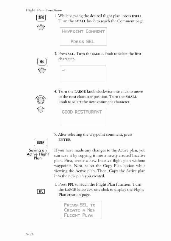
1. While viewing the desired flight plan, press INFO.
Turn the SMALL knob to reach the Comment page.
Waypoint Comment
Press SEL
3. Press SEL. Turn the SMALL knob to select the first
character.
_
4. Turn the LARGE knob clockwise one click to move
to the next character position. Turn the SMALL
knob to select the next comment character.
GOOD RESTAURANT
5. After selecting the waypoint comment, press
ENTER.
Saving anActive Flight
Plan
If you have made any changes to the Active plan, you
can save it by copying it into a newly created Inactive
plan. First, create a new Inactive flight plan without
waypoints. Next, select the Copy Plan option while
viewing the Active plan. Then, Copy the Active plan
into the new plan you created.
1. Press FPL to reach the Flight Plan function. Turn
the LARGE knob ccw one click to display the Flight
Plan creation page.
Press SEL to
Create a New
Flight Plan
6-24
Flight Plan Functions
FPL
INFO
SEL
ENTER
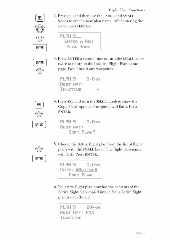
2. Press SEL and then use the LARGE and SMALL
knobs to enter a new plan name. After entering the
name, press ENTER.
PLAN 9__
Enter a New
Plan Name
3. Press ENTER a second time or turn the SMALL knob
twice to return to the Inactive Flight Plan name
page. Don’t insert any waypoints.
PLAN 9 0.0nm
Dest wpt: ——
Inactive ·
4. Press SEL and turn the SMALL knob to show the
Copy Plan? option. The option will flash. Press
ENTER.
PLAN 9 0.0nm
Dest wpt: ——
Copy Plan?
5. Choose the Active flight plan from the list of flight
plans with the SMALL knob. The flight plan name
will flash. Press ENTER.
PLAN 9 0.0nm
Copy: *Active*
Copy Plan
6. Your new flight plan now has the contents of the
Active flight plan copied into it. Your Active flight
plan is not affected.
PLAN 9 204nm
Dest Wpt: PDX
Inactive
6-25
Flight Plan Functions
SEL
ENTER
ENTER
ENTER
ENTER
SEL

An old navigation method1. While holding your watch horizontal, point the
hour hand at the sun.
2. Halfway between the hour hand and 12:00 is south.
Don’t always depend on this method, but it is kind of
fun.
6-26
Flight Plan Functions
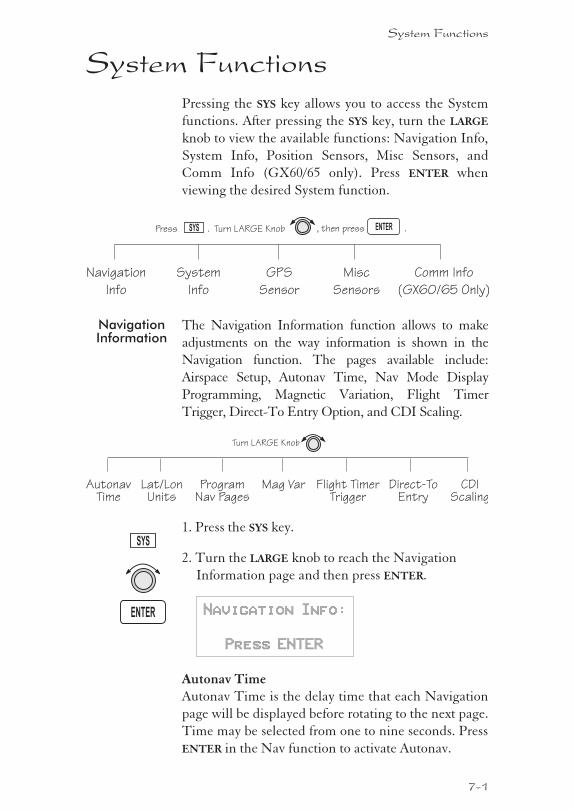
System FunctionsPressing the SYS key allows you to access the System
functions. After pressing the SYS key, turn the LARGE
knob to view the available functions: Navigation Info,
System Info, Position Sensors, Misc Sensors, and
Comm Info (GX60/65 only). Press ENTER when
viewing the desired System function.
NavigationInformation
The Navigation Information function allows to make
adjustments on the way information is shown in the
Navigation function. The pages available include:
Airspace Setup, Autonav Time, Nav Mode Display
Programming, Magnetic Variation, Flight Timer
Trigger, Direct-To Entry Option, and CDI Scaling.
1. Press the SYS key.
2. Turn the LARGE knob to reach the Navigation
Information page and then press ENTER.
Navigation Info:
Press ENTER
Autonav TimeAutonav Time is the delay time that each Navigation
page will be displayed before rotating to the next page.
Time may be selected from one to nine seconds. Press
ENTER in the Nav function to activate Autonav.
System Functions
7-1
SYS
ENTER
Navigation
Info
System
Info
GPS
Sensor
Misc
Sensors
Comm Info
(GX60/65 Only)
Turn LARGE Knob , then press .SYS ENTERPress .
AutonavTime
ProgramNav Pages
Mag Var Flight TimerTrigger
Direct-ToEntry
Turn LARGE Knob
CDIScaling
Lat/LonUnits
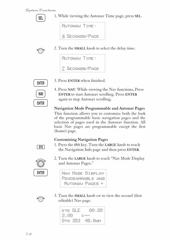
1. While viewing the Autonav Time page, press SEL.
Autonav Time:
4 Seconds/Page
2. Turn the SMALL knob to select the delay time.
Autonav Time:
7 Seconds/Page
3. Press ENTER when finished.
4. Press NAV. While viewing the Nav functions, PressENTER to start Autonav scrolling. Press ENTER
again to stop Autonav scrolling.
Navigation Mode Programmable and Autonav PagesThis function allows you to customize both the lookof the programmable basic navigation pages and theselection of pages used in the Autonav function. Allbasic Nav pages are programmable except the first(home) page.
Customizing Navigation Pages1. Press the SYS key. Turn the LARGE knob to reach
the Navigation Info page and then press ENTER.
2. Turn the LARGE knob to reach “Nav Mode Displayand Autonav Pages.”
Nav Mode Display
Programmable and
Autonav Pages ·
3. Turn the SMALL knob cw to view the second (firsteditable) Nav page.
ete SLE 00:20
2.00 “¼¼
Dtk 353 48.0nm
7-2
System Functions
NAV
ENTER
ENTER
ENTER
SYS
SEL
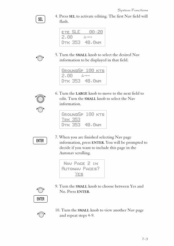
4. Press SEL to activate editing. The first Nav field will
flash.
ete SLE 00:20
2.00 “¼¼
Dtk 353 48.0nm
5. Turn the SMALL knob to select the desired Nav
information to be displayed in that field.
GroundSp 100 kts
2.00 “¼¼
Dtk 353 48.0nm
6. Turn the LARGE knob to move to the next field to
edit. Turn the SMALL knob to select the Nav
information.
GroundSp 100 kts
Trk 353
Dtk 353 48.0nm
7. When you are finished selecting Nav page
information, press ENTER. You will be prompted to
decide if you want to include this page in the
Autonav scrolling.
Nav Page 2 in
Autonav Pages?
Yes
9. Turn the SMALL knob to choose between Yes and
No. Press ENTER.
10. Turn the SMALL knob to view another Nav page
and repeat steps 4-9.
7-3
System Functions
ENTER
ENTER
SEL
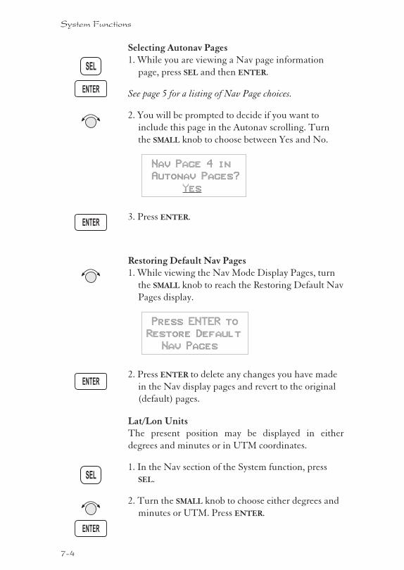
Selecting Autonav Pages1. While you are viewing a Nav page information
page, press SEL and then ENTER.
See page 5 for a listing of Nav Page choices.
2. You will be prompted to decide if you want to
include this page in the Autonav scrolling. Turn
the SMALL knob to choose between Yes and No.
Nav Page 4 in
Autonav Pages?
Yes
3. Press ENTER.
Restoring Default Nav Pages1. While viewing the Nav Mode Display Pages, turn
the SMALL knob to reach the Restoring Default Nav
Pages display.
Press ENTER to
Restore Default
Nav Pages
2. Press ENTER to delete any changes you have made
in the Nav display pages and revert to the original
(default) pages.
Lat/Lon UnitsThe present position may be displayed in either
degrees and minutes or in UTM coordinates.
1. In the Nav section of the System function, press
SEL.
2. Turn the SMALL knob to choose either degrees and
minutes or UTM. Press ENTER.
7-4
System Functions
SEL
ENTER
ENTER
ENTER
ENTER
SEL
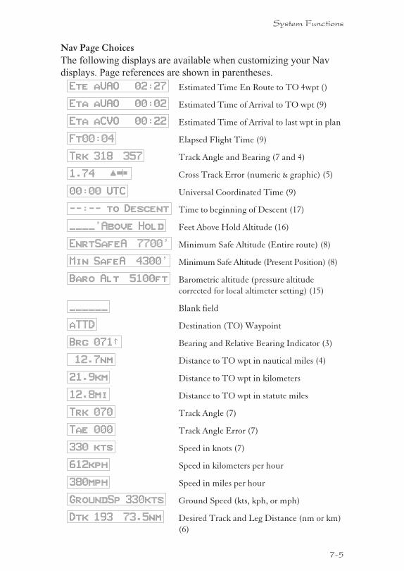
Nav Page Choices
The following displays are available when customizing your Nav
displays. Page references are shown in parentheses.
Ete aUAO 02:27 Estimated Time En Route to TO 4wpt ()
Eta aUAO 00:02 Estimated Time of Arrival to TO wpt (9)
Eta aCVO 00:22 Estimated Time of Arrival to last wpt in plan
Ft00:04 Elapsed Flight Time (9)
Trk 318 357 Track Angle and Bearing (7 and 4)
1.74 崬 Cross Track Error (numeric & graphic) (5)
00:00 UTC Universal Coordinated Time (9)
--:-- to Descent Time to beginning of Descent (17)
____’Above Hold Feet Above Hold Altitude (16)
EnrtSafeA 7700’ Minimum Safe Altitude (Entire route) (8)
Min SafeA 4300’ Minimum Safe Altitude (Present Position) (8)
Baro Alt 5100ft Barometric altitude (pressure altitude
corrected for local altimeter setting) (15)
______ Blank field
aTTD Destination (TO) Waypoint
Brg 071½ Bearing and Relative Bearing Indicator (3)
12.7nm Distance to TO wpt in nautical miles (4)
21.9km Distance to TO wpt in kilometers
12.8mi Distance to TO wpt in statute miles
Trk 070 Track Angle (7)
Tae 000 Track Angle Error (7)
330 kts Speed in knots (7)
612kph Speed in kilometers per hour
380mph Speed in miles per hour
GroundSp 330kts Ground Speed (kts, kph, or mph)
Dtk 193 73.5nm Desired Track and Leg Distance (nm or km)
(6)
7-5
System Functions

Setting Units of MeasurementNav displays that show distance may be selected to
show either nautical miles, statute miles, or
kilometers.
1. In the Navigation section of the System function,
turn the LARGE knob to the Nav Mode Display
Pages.
Nav Mode Display
Programmable and
Autonav Pages ·
2. Turn the SMALL knob to reach a programmable
Nav page.
ete SLE 00:20
2.00 “¼¼
Dtk 353 48.0nm
3. Press SEL to start field selection. Turn the LARGE
knob to the desired field.
ete SLE 00:20
2.00 “¼¼
Dtk 353 48.0nm
4. Turn the SMALL knob to select the field with
different units. Press ENTER to save the changes.
Press SEL to stop editing and ignore any changes.
ete SLE 00:20
2.00 “¼¼
Dtk 353 89.10km
7-6
System Functions
SEL
ENTER
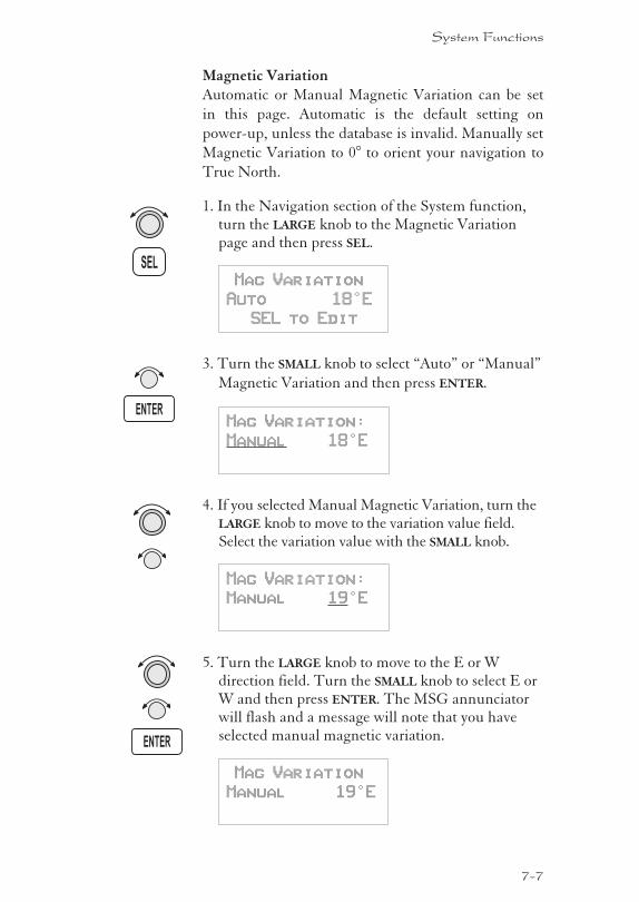
Magnetic VariationAutomatic or Manual Magnetic Variation can be set
in this page. Automatic is the default setting on
power-up, unless the database is invalid. Manually set
Magnetic Variation to 0° to orient your navigation to
True North.
1. In the Navigation section of the System function,turn the LARGE knob to the Magnetic Variationpage and then press SEL.
Mag Variation
Auto 18°E
SEL to Edit
3. Turn the SMALL knob to select “Auto” or “Manual”
Magnetic Variation and then press ENTER.
Mag Variation:
Manual 18°E
4. If you selected Manual Magnetic Variation, turn theLARGE knob to move to the variation value field.Select the variation value with the SMALL knob.
Mag Variation:
Manual 19°E
5. Turn the LARGE knob to move to the E or Wdirection field. Turn the SMALL knob to select E orW and then press ENTER. The MSG annunciatorwill flash and a message will note that you haveselected manual magnetic variation.
Mag Variation
Manual 19°E
7-7
System Functions
SEL
ENTER
ENTER
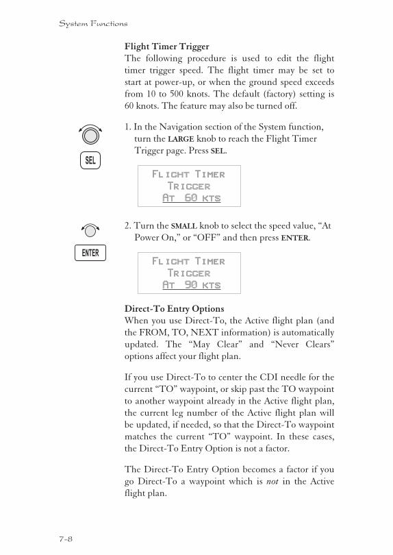
Flight Timer TriggerThe following procedure is used to edit the flight
timer trigger speed. The flight timer may be set to
start at power-up, or when the ground speed exceeds
from 10 to 500 knots. The default (factory) setting is
60 knots. The feature may also be turned off.
1. In the Navigation section of the System function,
turn the LARGE knob to reach the Flight Timer
Trigger page. Press SEL.
Flight Timer
Trigger
At 60 kts
2. Turn the SMALL knob to select the speed value, “At
Power On,” or “OFF” and then press ENTER.
Flight Timer
Trigger
At 90 kts
Direct-To Entry OptionsWhen you use Direct-To, the Active flight plan (and
the FROM, TO, NEXT information) is automatically
updated. The “May Clear” and “Never Clears”
options affect your flight plan.
If you use Direct-To to center the CDI needle for the
current “TO” waypoint, or skip past the TO waypoint
to another waypoint already in the Active flight plan,
the current leg number of the Active flight plan will
be updated, if needed, so that the Direct-To waypoint
matches the current “TO” waypoint. In these cases,
the Direct-To Entry Option is not a factor.
The Direct-To Entry Option becomes a factor if you
go Direct-To a waypoint which is not in the Active
flight plan.
7-8
System Functions
ENTER
SEL
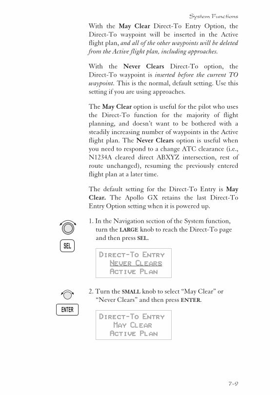
With the May Clear Direct-To Entry Option, the
Direct-To waypoint will be inserted in the Active
flight plan, and all of the other waypoints will be deleted
from the Active flight plan, including approaches.
With the Never Clears Direct-To option, the
Direct-To waypoint is inserted before the current TO
waypoint. This is the normal, default setting. Use this
setting if you are using approaches.
The May Clear option is useful for the pilot who uses
the Direct-To function for the majority of flight
planning, and doesn’t want to be bothered with a
steadily increasing number of waypoints in the Active
flight plan. The Never Clears option is useful when
you need to respond to a change ATC clearance (i.e.,
N1234A cleared direct ABXYZ intersection, rest of
route unchanged), resuming the previously entered
flight plan at a later time.
The default setting for the Direct-To Entry is May
Clear. The Apollo GX retains the last Direct-To
Entry Option setting when it is powered up.
1. In the Navigation section of the System function,
turn the LARGE knob to reach the Direct-To page
and then press SEL.
Direct-To Entry
Never Clears
Active Plan
2. Turn the SMALL knob to select “May Clear” or
“Never Clears” and then press ENTER.
Direct-To Entry
May Clear
Active Plan
7-9
System Functions
ENTER
SEL
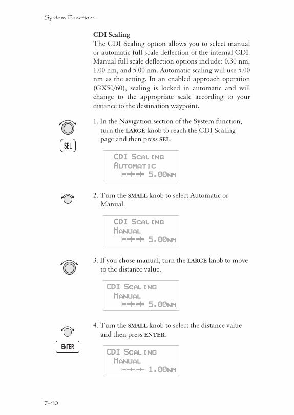
CDI ScalingThe CDI Scaling option allows you to select manual
or automatic full scale deflection of the internal CDI.
Manual full scale deflection options include: 0.30 nm,
1.00 nm, and 5.00 nm. Automatic scaling will use 5.00
nm as the setting. In an enabled approach operation
(GX50/60), scaling is locked in automatic and will
change to the appropriate scale according to your
distance to the destination waypoint.
1. In the Navigation section of the System function,
turn the LARGE knob to reach the CDI Scaling
page and then press SEL.
CDI Scaling
Automatic
ªªªªª 5.00nm
2. Turn the SMALL knob to select Automatic or
Manual.
CDI Scaling
Manual
ªªªªª 5.00nm
3. If you chose manual, turn the LARGE knob to move
to the distance value.
CDI Scaling
Manual
ªªªªª 5.00nm
4. Turn the SMALL knob to select the distance value
and then press ENTER.
CDI Scaling
Manual
––––– 1.00nm
7-10
System Functions
SEL
ENTER
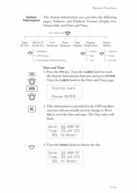
SystemInformation
The System Information area provides the following
pages: Software and Database Version, Display test,
Owner Info, and Date and Time, .
Date and Time1. Press the SYS key. Turn the LARGE knob to reach
the System Information function and press ENTER.
Turn the LARGE knob to the Date and Time page.
System Info
Press ENTER
2. This information is provided by the GPS satellites
and you will not usually need to change it. Press
SEL to reset the date and time. The Day value will
flash.
Date: 03 MAR 97
Time: 23:24 UTC
SEL to Reset
4. Turn the SMALL knob to choose the day.
Date: 24 MAR 97
Time: 23:24 UTC
SEL to Reset
7-11
System Functions
SYS
ENTER
SEL
Date& Time
SW Ver &Serial No.
FuelMeasure
BaroMeasure
TestDisplay
Turn LARGE Knob
OwnerName
Database
GPS Sensor
Comm Radio (GX60/65 Only)
Address
Phone
Aircraft
DisplayBrightness
Default
High
Low
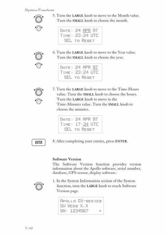
5. Turn the LARGE knob to move to the Month value.
Turn the SMALL knob to choose the month.
Date: 24 APR 97
Time: 23:24 UTC
SEL to Reset
6. Turn the LARGE knob to move to the Year value.
Turn the SMALL knob to choose the year.
Date: 24 APR 97
Time: 23:24 UTC
SEL to Reset
7. Turn the LARGE knob to move to the Time-Hours
value. Turn the SMALL knob to choose the hours.
Turn the LARGE knob to move to the
Time-Minutes value. Turn the SMALL knob to
choose the minutes.
Date: 24 APR 97
Time: 17:34 UTC
SEL to Reset
8. After completing your entries, press ENTER.
Software VersionThe Software Version function provides versioninformation about the Apollo software, serial number,database, GPS sensor, display software.
1. In the System Information section of the System
function, turn the LARGE knob to reach Software
Version page.
Apollo GX-series
SW Vers X.X
SN: 1234567 ·
7-12
System Functions
ENTER
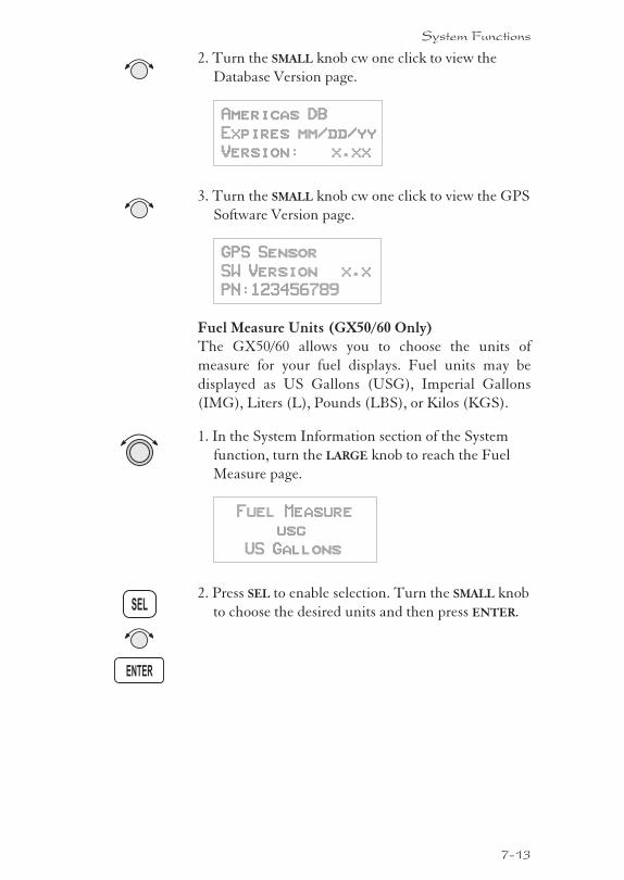
2. Turn the SMALL knob cw one click to view the
Database Version page.
Americas DB
Expires mm/dd/yy
Version: x.xx
3. Turn the SMALL knob cw one click to view the GPS
Software Version page.
GPS Sensor
SW Version x.x
PN:123456789
Fuel Measure Units (GX50/60 Only)The GX50/60 allows you to choose the units of
measure for your fuel displays. Fuel units may be
displayed as US Gallons (USG), Imperial Gallons
(IMG), Liters (L), Pounds (LBS), or Kilos (KGS).
1. In the System Information section of the System
function, turn the LARGE knob to reach the Fuel
Measure page.
Fuel Measure
usg
US Gallons
2. Press SEL to enable selection. Turn the SMALL knob
to choose the desired units and then press ENTER.
7-13
System Functions
SEL
ENTER
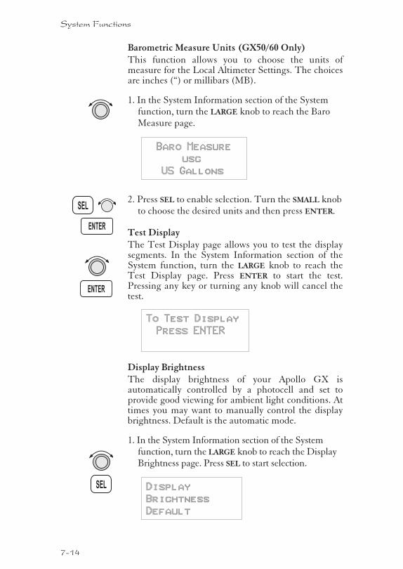
Barometric Measure Units (GX50/60 Only)This function allows you to choose the units ofmeasure for the Local Altimeter Settings. The choicesare inches (“) or millibars (MB).
1. In the System Information section of the Systemfunction, turn the LARGE knob to reach the BaroMeasure page.
Baro Measure
usg
US Gallons
2. Press SEL to enable selection. Turn the SMALL knobto choose the desired units and then press ENTER.
Test DisplayThe Test Display page allows you to test the displaysegments. In the System Information section of theSystem function, turn the LARGE knob to reach theTest Display page. Press ENTER to start the test.Pressing any key or turning any knob will cancel thetest.
To Test Display
Press ENTER
Display BrightnessThe display brightness of your Apollo GX isautomatically controlled by a photocell and set toprovide good viewing for ambient light conditions. Attimes you may want to manually control the displaybrightness. Default is the automatic mode.
1. In the System Information section of the Systemfunction, turn the LARGE knob to reach the DisplayBrightness page. Press SEL to start selection.
Display
Brightness
Default
7-14
System Functions
SEL
ENTER
ENTER
SEL
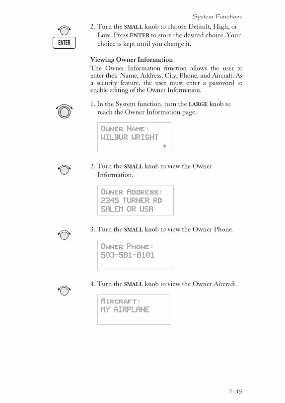
2. Turn the SMALL knob to choose Default, High, or
Low. Press ENTER to store the desired choice. Your
choice is kept until you change it.
Viewing Owner InformationThe Owner Information function allows the user toenter their Name, Address, City, Phone, and Aircraft. Asa security feature, the user must enter a password toenable editing of the Owner Information.
1. In the System function, turn the LARGE knob toreach the Owner Information page.
Owner Name:
WILBUR WRIGHT
·
2. Turn the SMALL knob to view the Owner
Information.
Owner Address:
2345 TURNER RD
SALEM OR USA
3. Turn the SMALL knob to view the Owner Phone.
Owner Phone:
503-581-8101
4. Turn the SMALL knob to view the Owner Aircraft.
Aircraft:
MY AIRPLANE
7-15
System Functions
ENTER
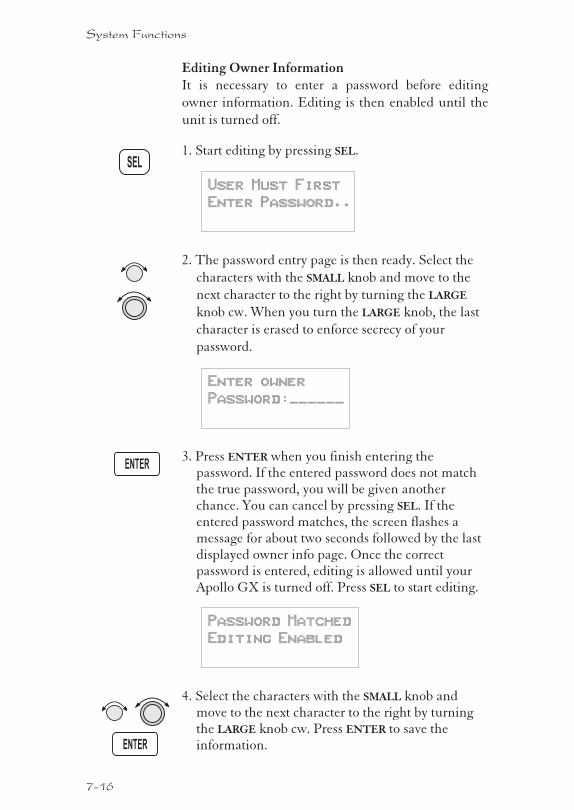
Editing Owner InformationIt is necessary to enter a password before editing
owner information. Editing is then enabled until the
unit is turned off.
1. Start editing by pressing SEL.
User Must First
Enter Password..
2. The password entry page is then ready. Select the
characters with the SMALL knob and move to the
next character to the right by turning the LARGE
knob cw. When you turn the LARGE knob, the last
character is erased to enforce secrecy of your
password.
Enter owner
Password:______
3. Press ENTER when you finish entering thepassword. If the entered password does not matchthe true password, you will be given anotherchance. You can cancel by pressing SEL. If theentered password matches, the screen flashes amessage for about two seconds followed by the lastdisplayed owner info page. Once the correctpassword is entered, editing is allowed until yourApollo GX is turned off. Press SEL to start editing.
Password Matched
Editing Enabled
4. Select the characters with the SMALL knob andmove to the next character to the right by turningthe LARGE knob cw. Press ENTER to save theinformation.
7-16
System Functions
ENTER
ENTER
SEL
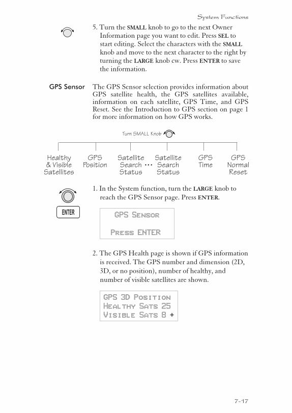
5. Turn the SMALL knob to go to the next OwnerInformation page you want to edit. Press SEL tostart editing. Select the characters with the SMALL
knob and move to the next character to the right byturning the LARGE knob cw. Press ENTER to savethe information.
GPS Sensor The GPS Sensor selection provides information aboutGPS satellite health, the GPS satellites available,information on each satellite, GPS Time, and GPSReset. See the Introduction to GPS section on page 1for more information on how GPS works.
1. In the System function, turn the LARGE knob to
reach the GPS Sensor page. Press ENTER.
GPS Sensor
Press ENTER
2. The GPS Health page is shown if GPS information
is received. The GPS number and dimension (2D,
3D, or no position), number of healthy, and
number of visible satellites are shown.
GPS 3D Position
Healthy Sats 25
Visible Sats 8 Y
7-17
System Functions
ENTER
Healthy& Visible
Satellites
SatelliteSearchStatus
GPSTime
Turn SMALL Knob
GPSNormalReset
GPSPosition
SatelliteSearchStatus
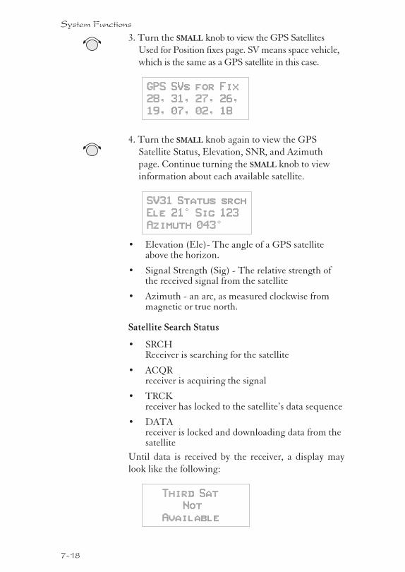
3. Turn the SMALL knob to view the GPS Satellites
Used for Position fixes page. SV means space vehicle,
which is the same as a GPS satellite in this case.
GPS SVs for Fix
28, 31, 27, 26,
19, 07, 02, 18
4. Turn the SMALL knob again to view the GPS
Satellite Status, Elevation, SNR, and Azimuth
page. Continue turning the SMALL knob to view
information about each available satellite.
SV31 Status srch
Ele 21° Sig 123
Azimuth 043°
� Elevation (Ele)- The angle of a GPS satelliteabove the horizon.
� Signal Strength (Sig) - The relative strength ofthe received signal from the satellite
� Azimuth - an arc, as measured clockwise frommagnetic or true north.
Satellite Search Status
� SRCHReceiver is searching for the satellite
� ACQRreceiver is acquiring the signal
� TRCKreceiver has locked to the satellite’s data sequence
� DATAreceiver is locked and downloading data from thesatellite
Until data is received by the receiver, a display may
look like the following:
Third Sat
Not
Available
7-18
System Functions
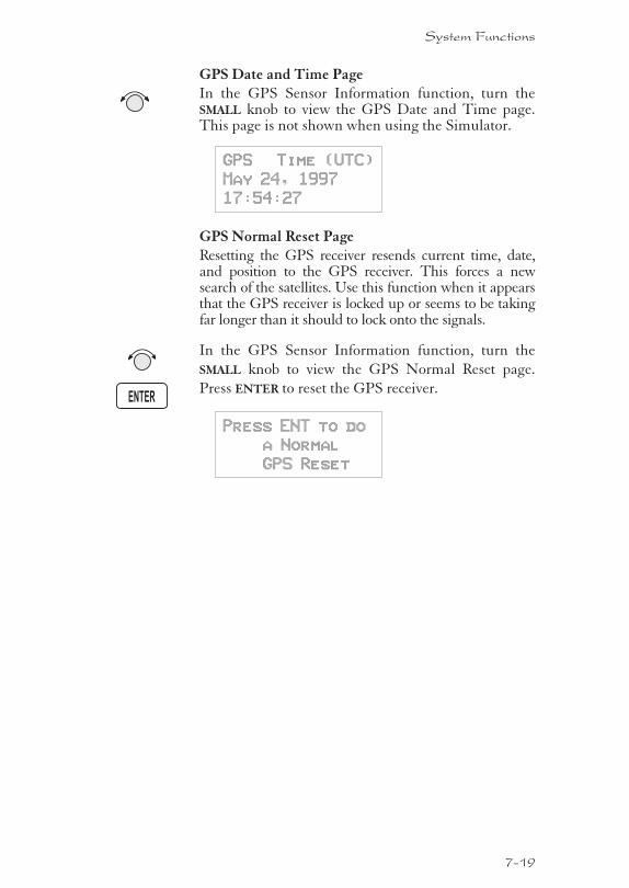
GPS Date and Time PageIn the GPS Sensor Information function, turn theSMALL knob to view the GPS Date and Time page.This page is not shown when using the Simulator.
GPS Time (UTC)
May 24, 1997
17:54:27
GPS Normal Reset PageResetting the GPS receiver resends current time, date,and position to the GPS receiver. This forces a newsearch of the satellites. Use this function when it appearsthat the GPS receiver is locked up or seems to be takingfar longer than it should to lock onto the signals.
In the GPS Sensor Information function, turn the
SMALL knob to view the GPS Normal Reset page.
Press ENTER to reset the GPS receiver.
Press ENT to do
a Normal
GPS Reset
7-19
System Functions
ENTER
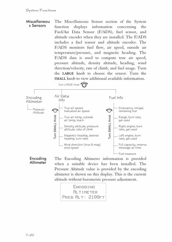
Miscellaneous Sensors
The Miscellaneous Sensor section of the System
function displays information concerning the
Fuel/Air Data Sensor (F/ADS), fuel sensor, and
altitude encoder when they are installed. The F/ADS
includes a fuel sensor and altitude encoder. The
F/ADS monitors fuel flow, air speed, outside air
temperature/pressure, and magnetic heading. The
F/ADS data is used to compute true air speed,
pressure altitude, density altitude, heading, wind
direction/velocity, rate of climb, and fuel usage. Turn
the LARGE knob to choose the sensor. Turn the
SMALL knob to view additional available information.
EncodingAltimeter
The Encoding Altimeter information is provided
when a suitable device has been installed. The
Pressure Altitude value is provided by the encoding
altimeter is shown on this display. This is the current
altitude without barometric pressure adjustment.
Encoding
Altimeter
Pres Alt: 2100ft
7-20
System Functions
Air DataInfo
Turn LARGE Knob
True air speed,Indicated air speed
True air temp, outsideair temp, mach
Density altitude, pressurealtitude, rate of climb
Magnetic heading, desiredheading, turn rate
Wind direction (true & mag)wind speed
Tu
rnS
MA
LL
Kn
ob
EncodingAltimeter
PressureAltitude
Fuel Info
Endurance, nm/gal,remaining fuel
Range, burn rate,gal used
Right engine, burnrate, gal used
Left engine, burnrate, gal used
Full capacity, reserve,message at time
Fuel measure
Tu
rnS
MA
LL
Kn
ob
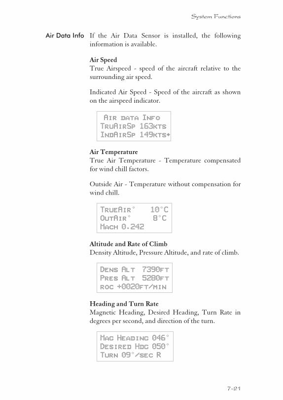
Air Data Info If the Air Data Sensor is installed, the following
information is available.
Air SpeedTrue Airspeed - speed of the aircraft relative to the
surrounding air speed.
Indicated Air Speed - Speed of the aircraft as shown
on the airspeed indicator.
Air data Info
TruAirSp 163kts
IndAirSp 149kts·
Air TemperatureTrue Air Temperature - Temperature compensated
for wind chill factors.
Outside Air - Temperature without compensation for
wind chill.
TrueAir° 10°C
OutAir° 8°C
Mach 0.242
Altitude and Rate of ClimbDensity Altitude, Pressure Altitude, and rate of climb.
Dens Alt 7390ft
Pres Alt 5280ft
roc +0020ft/min
Heading and Turn RateMagnetic Heading, Desired Heading, Turn Rate in
degrees per second, and direction of the turn.
Mag Heading 046°
Desired Hdg 050°
Turn 09°/sec R
7-21
System Functions
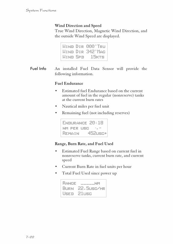
Wind Direction and SpeedTrue Wind Direction, Magnetic Wind Direction, and
the outside Wind Speed are displayed.
Wind Dir 000°Tru
Wind Dir 342°Mag
Wind Spd 15kts
Fuel Info An installed Fuel Data Sensor will provide the
following information.
Fuel Endurance
� Estimated fuel Endurance based on the currentamount of fuel in the regular (nonreserve) tanksat the current burn rates
� Nautical miles per fuel unit
� Remaining fuel (not including reserves)
Endurance 20:18
nm per usg —.-
Remain 452usg·
Range, Burn Rate, and Fuel Used
� Estimated Fuel Range based on current fuel innonreserve tanks, current burn rate, and currentspeed
� Current Burn Rate in fuel units per hour
� Total Fuel Used since power up
Range _____nm
Burn 22.5usg/hr
Used 21usg
7-22
System Functions
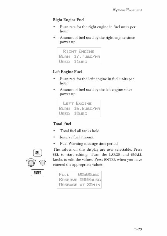
Right Engine Fuel
� Burn rate for the right engine in fuel units perhour
� Amount of fuel used by the right engine sincepower up
Right Engine
Burn 17.7usg/hr
Used 11usg
Left Engine Fuel
� Burn rate for the leftt engine in fuel units perhour
� Amount of fuel used by the left engine sincepower up
Left Engine
Burn 16.8usg/hr
Used 10usg
Total Fuel
� Total fuel all tanks hold
� Reserve fuel amount
� Fuel Warning message time period
The values on this display are user selectable. Press
SEL to start editing. Turn the LARGE and SMALL
knobs to edit the values. Press ENTER when you have
entered the appropriate values.
Full 00500usg
Reserve 00025usg
Message at 30min
7-23
System Functions
ENTER
SEL
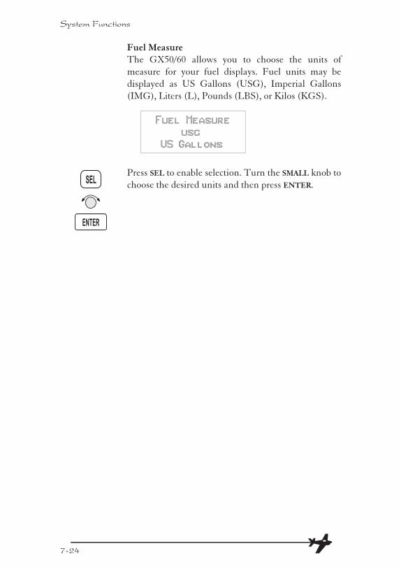
Fuel MeasureThe GX50/60 allows you to choose the units of
measure for your fuel displays. Fuel units may be
displayed as US Gallons (USG), Imperial Gallons
(IMG), Liters (L), Pounds (LBS), or Kilos (KGS).
Fuel Measure
usg
US Gallons
Press SEL to enable selection. Turn the SMALL knob to
choose the desired units and then press ENTER.
7-24
System Functions
SEL
ENTER
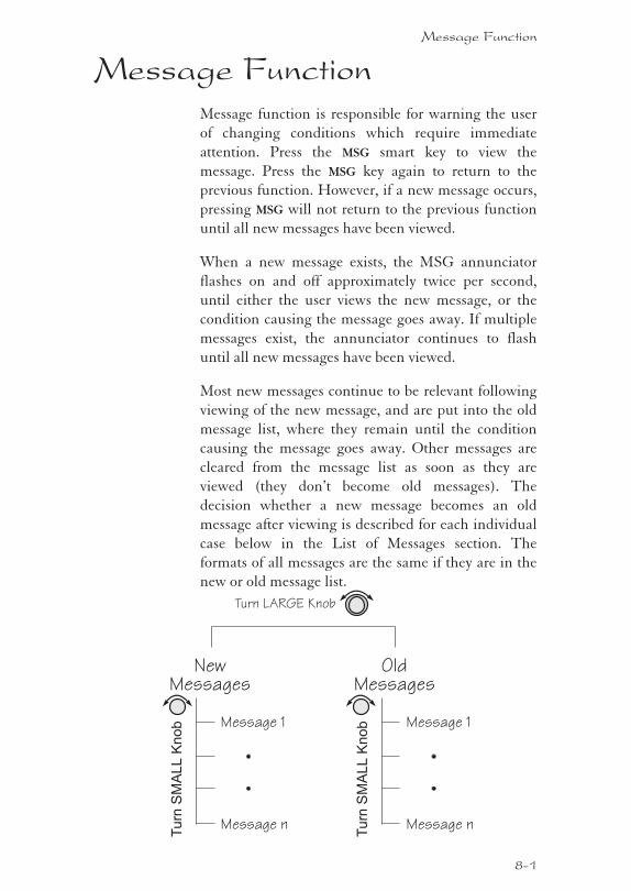
Message FunctionMessage function is responsible for warning the user
of changing conditions which require immediate
attention. Press the MSG smart key to view the
message. Press the MSG key again to return to the
previous function. However, if a new message occurs,
pressing MSG will not return to the previous function
until all new messages have been viewed.
When a new message exists, the MSG annunciator
flashes on and off approximately twice per second,
until either the user views the new message, or the
condition causing the message goes away. If multiple
messages exist, the annunciator continues to flash
until all new messages have been viewed.
Most new messages continue to be relevant following
viewing of the new message, and are put into the old
message list, where they remain until the condition
causing the message goes away. Other messages are
cleared from the message list as soon as they are
viewed (they don’t become old messages). The
decision whether a new message becomes an old
message after viewing is described for each individual
case below in the List of Messages section. The
formats of all messages are the same if they are in the
new or old message list.
Message Function
8-1
OldMessages
Turn LARGE Knob
Tu
rnS
MA
LL
Kn
ob Message 1
Message n
NewMessages
Tu
rnS
MA
LL
Kn
ob Message 1
Message n
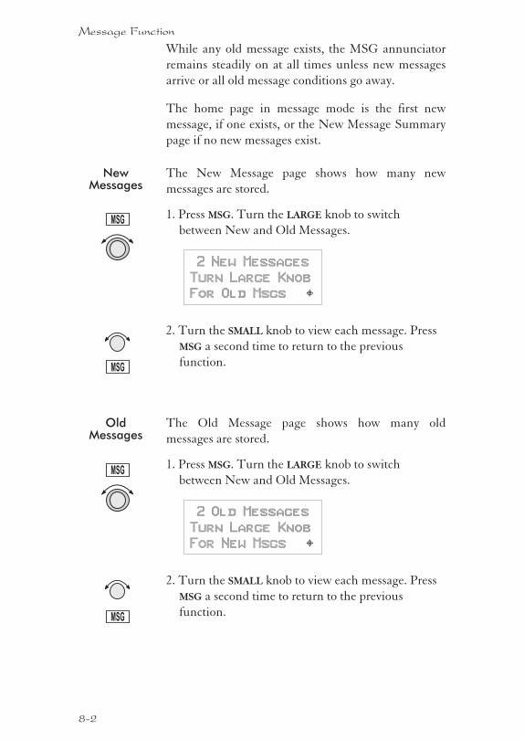
While any old message exists, the MSG annunciator
remains steadily on at all times unless new messages
arrive or all old message conditions go away.
The home page in message mode is the first new
message, if one exists, or the New Message Summary
page if no new messages exist.
NewMessages
The New Message page shows how many new
messages are stored.
1. Press MSG. Turn the LARGE knob to switch
between New and Old Messages.
2 New Messages
Turn Large Knob
For Old Msgs Y
2. Turn the SMALL knob to view each message. Press
MSG a second time to return to the previous
function.
OldMessages
The Old Message page shows how many old
messages are stored.
1. Press MSG. Turn the LARGE knob to switch
between New and Old Messages.
2 Old Messages
Turn Large Knob
For New Msgs Y
2. Turn the SMALL knob to view each message. Press
MSG a second time to return to the previous
function.
8-2
Message Function
MSG
MSG
MSG
MSG
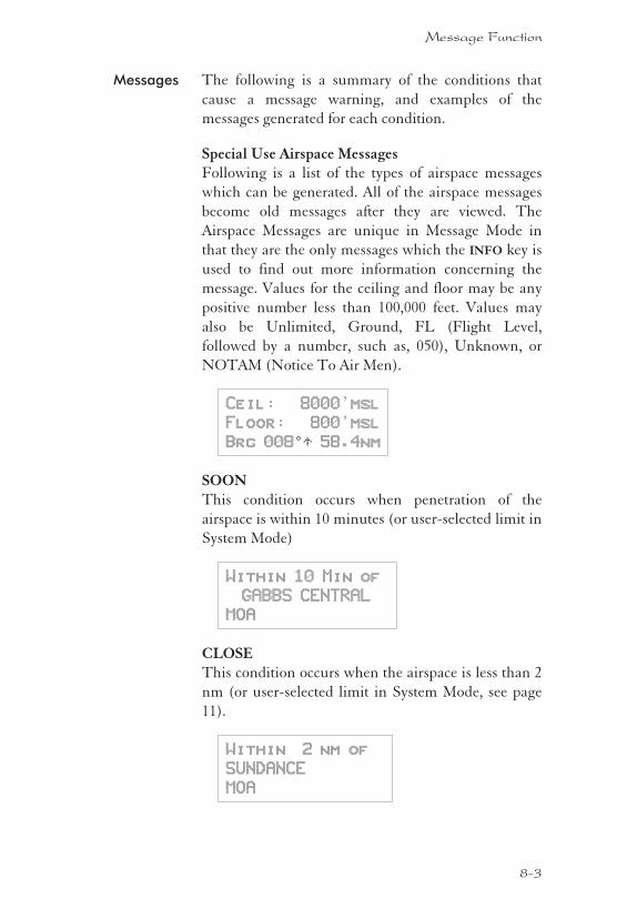
Messages The following is a summary of the conditions that
cause a message warning, and examples of the
messages generated for each condition.
Special Use Airspace MessagesFollowing is a list of the types of airspace messages
which can be generated. All of the airspace messages
become old messages after they are viewed. The
Airspace Messages are unique in Message Mode in
that they are the only messages which the INFO key is
used to find out more information concerning the
message. Values for the ceiling and floor may be any
positive number less than 100,000 feet. Values may
also be Unlimited, Ground, FL (Flight Level,
followed by a number, such as, 050), Unknown, or
NOTAM (Notice To Air Men).
Ceil: 8000’msl
Floor: 800’msl
Brg 0080T 58.4nm
SOONThis condition occurs when penetration of the
airspace is within 10 minutes (or user-selected limit in
System Mode)
Within 10 Min of
GABBS CENTRAL
MOA
CLOSEThis condition occurs when the airspace is less than 2
nm (or user-selected limit in System Mode, see page
11).
Within 2 nm of
SUNDANCE
MOA
8-3
Message Function
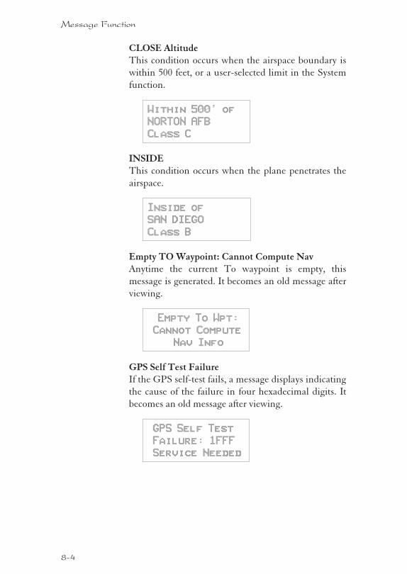
CLOSE AltitudeThis condition occurs when the airspace boundary is
within 500 feet, or a user-selected limit in the System
function.
Within 500’ of
NORTON AFB
Class C
INSIDEThis condition occurs when the plane penetrates the
airspace.
Inside of
SAN DIEGO
Class B
Empty TO Waypoint: Cannot Compute NavAnytime the current To waypoint is empty, this
message is generated. It becomes an old message after
viewing.
Empty To Wpt:
Cannot Compute
Nav Info
GPS Self Test FailureIf the GPS self-test fails, a message displays indicating
the cause of the failure in four hexadecimal digits. It
becomes an old message after viewing.
GPS Self Test
Failure: 1FFF
Service Needed
8-4
Message Function
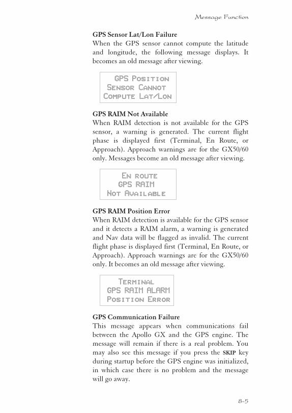
GPS Sensor Lat/Lon FailureWhen the GPS sensor cannot compute the latitude
and longitude, the following message displays. It
becomes an old message after viewing.
GPS Position
Sensor Cannot
Compute Lat/Lon
GPS RAIM Not AvailableWhen RAIM detection is not available for the GPS
sensor, a warning is generated. The current flight
phase is displayed first (Terminal, En Route, or
Approach). Approach warnings are for the GX50/60
only. Messages become an old message after viewing.
En route
GPS RAIM
Not Available
GPS RAIM Position ErrorWhen RAIM detection is available for the GPS sensor
and it detects a RAIM alarm, a warning is generated
and Nav data will be flagged as invalid. The current
flight phase is displayed first (Terminal, En Route, or
Approach). Approach warnings are for the GX50/60
only. It becomes an old message after viewing.
Terminal
GPS RAIM ALARM
Position Error
GPS Communication FailureThis message appears when communications fail
between the Apollo GX and the GPS engine. The
message will remain if there is a real problem. You
may also see this message if you press the SKIP key
during startup before the GPS engine was initialized,
in which case there is no problem and the message
will go away.
8-5
Message Function
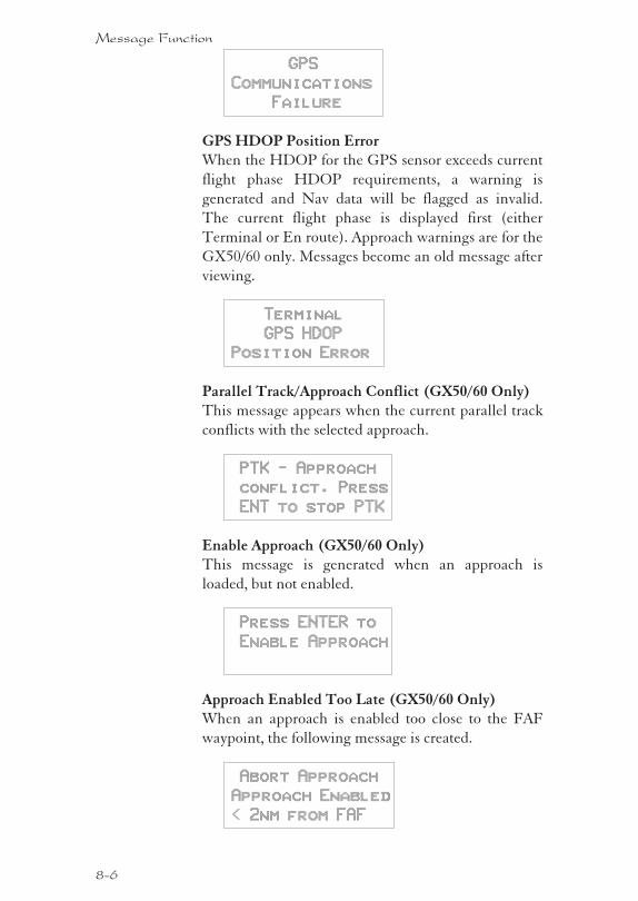
GPS
Communications
Failure
GPS HDOP Position ErrorWhen the HDOP for the GPS sensor exceeds current
flight phase HDOP requirements, a warning is
generated and Nav data will be flagged as invalid.
The current flight phase is displayed first (either
Terminal or En route). Approach warnings are for the
GX50/60 only. Messages become an old message after
viewing.
Terminal
GPS HDOP
Position Error
Parallel Track/Approach Conflict (GX50/60 Only)This message appears when the current parallel track
conflicts with the selected approach.
PTK - Approach
conflict. Press
ENT to stop PTK
Enable Approach (GX50/60 Only)This message is generated when an approach is
loaded, but not enabled.
Press ENTER to
Enable Approach
Approach Enabled Too Late (GX50/60 Only)When an approach is enabled too close to the FAF
waypoint, the following message is created.
Abort Approach
Approach Enabled
< 2nm from FAF
8-6
Message Function
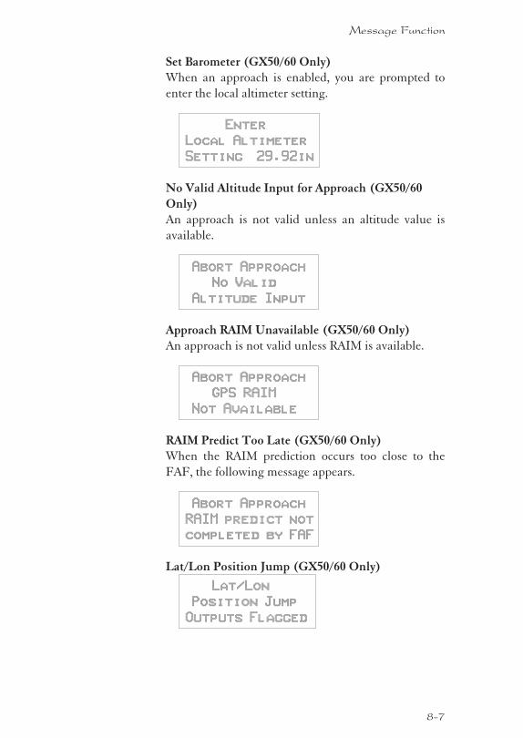
Set Barometer (GX50/60 Only)When an approach is enabled, you are prompted to
enter the local altimeter setting.
Enter
Local Altimeter
Setting 29.92in
No Valid Altitude Input for Approach (GX50/60
Only)An approach is not valid unless an altitude value is
available.
Abort Approach
No Valid
Altitude Input
Approach RAIM Unavailable (GX50/60 Only)An approach is not valid unless RAIM is available.
Abort Approach
GPS RAIM
Not Available
RAIM Predict Too Late (GX50/60 Only)When the RAIM prediction occurs too close to the
FAF, the following message appears.
Abort Approach
RAIM predict not
completed by FAF
Lat/Lon Position Jump (GX50/60 Only)
Lat/Lon
Position Jump
Outputs Flagged
8-7
Message Function
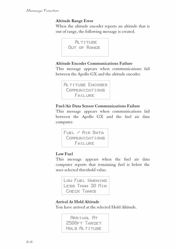
Altitude Range ErrorWhen the altitude encoder reports an altitude that is
out of range, the following message is created.
Altitude
Out of Range
Altitude Encoder Communications FailureThis message appears when communications fail
between the Apollo GX and the altitude encoder.
Altitude Encoder
Communications
Failure
Fuel/Air Data Sensor Communications FailureThis message appears when communications fail
between the Apollo GX and the fuel air data
computer.
Fuel / Air Data
Communications
Failure
Low FuelThis message appears when the fuel air data
computer reports that remaining fuel is below the
user-selected threshold value.
Low Fuel Warning
Less Than 30 Min
Check Tanks
Arrival At Hold AltitudeYou have arrived at the selected Hold Altitude.
Arrival At
2500ft Target
Hold Altitude
8-8
Message Function
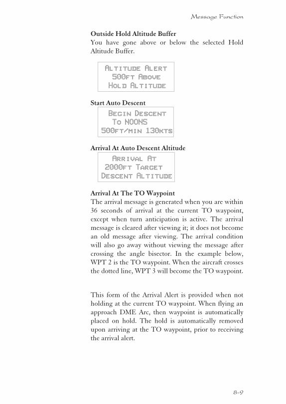
Outside Hold Altitude BufferYou have gone above or below the selected Hold
Altitude Buffer.
Altitude Alert
500ft Above
Hold Altitude
Start Auto Descent
Begin Descent
To NOONS
500ft/min 130kts
Arrival At Auto Descent Altitude
Arrival At
2000ft Target
Descent Altitude
Arrival At The TO WaypointThe arrival message is generated when you are within
36 seconds of arrival at the current TO waypoint,
except when turn anticipation is active. The arrival
message is cleared after viewing it; it does not become
an old message after viewing. The arrival condition
will also go away without viewing the message after
crossing the angle bisector. In the example below,
WPT 2 is the TO waypoint. When the aircraft crosses
the dotted line, WPT 3 will become the TO waypoint.
This form of the Arrival Alert is provided when not
holding at the current TO waypoint. When flying an
approach DME Arc, then waypoint is automatically
placed on hold. The hold is automatically removed
upon arriving at the TO waypoint, prior to receiving
the arrival alert.
8-9
Message Function
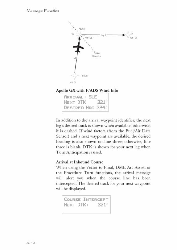
Apollo GX with F/ADS Wind Info
Arrival: SLE
Next DTK 321°
Desired Hdg 324°
In addition to the arrival waypoint identifier, the next
leg’s desired track is shown when available; otherwise,
it is dashed. If wind factors (from the Fuel/Air Data
Sensor) and a next waypoint are available, the desired
heading is also shown on line three; otherwise, line
three is blank. DTK is shown for your next leg when
Turn Anticipation is used.
Arrival at Inbound CourseWhen using the Vector to Final, DME Arc Assist, or
the Procedure Turn functions, the arrival message
will alert you when the course line has been
intercepted. The desired track for your next waypoint
will be displayed.
Course Intercept
Next DTK: 321°
8-10
Message Function
WPT 2 WPT 3
Leg 1
Leg 2
WPT 1
FROM
FROM
TOTO
Angle
Bisector
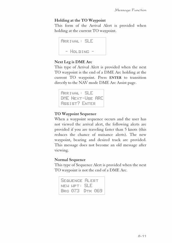
Holding at the TO WaypointThis form of the Arrival Alert is provided when
holding at the current TO waypoint.
Arrival: SLE
- Holding -
Next Leg is DME ArcThis type of Arrival Alert is provided when the next
TO waypoint is the end of a DME Arc holding at the
current TO waypoint. Press ENTER to transition
directly to the NAV mode DME Arc Assist page.
Arrival: SLE
DME Next-Use ARC
Assist? Enter
TO Waypoint SequenceWhen a waypoint sequence occurs and the user has
not viewed the arrival alert, the following alerts are
provided if you are traveling faster than 5 knots (this
reduces the chance of nuisance alerts). The new
waypoint, bearing and desired track are provided.
This message does not become an old message after
viewing.
Normal SequenceThis type of Sequence Alert is provided when the next
TO waypoint is not the end of a DME Arc.
Sequence Alert
new wpt: SLE
Brg 073 Dtk 069
8-11
Message Function
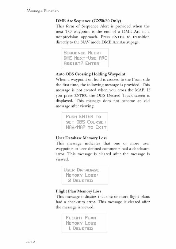
DME Arc Sequence (GX50/60 Only)This form of Sequence Alert is provided when the
next TO waypoint is the end of a DME Arc in a
nonprecision approach. Press ENTER to transition
directly to the NAV mode DME Arc Assist page.
Sequence Alert
DME Next-Use ARC
Assist? Enter
Auto OBS Crossing Holding WaypointWhen a waypoint on hold is crossed to the From side
the first time, the following message is provided. This
message is not created when you cross the MAP. If
you press ENTER, the OBS Desired Track screen is
displayed. This message does not become an old
message after viewing.
Push ENTER to
set OBS Course;
NAV/MAP to Exit
User Database Memory LossThis message indicates that one or more user
waypoints or user-defined comments had a checksum
error. This message is cleared after the message is
viewed.
User Database
Memory Loss:
2 Deleted
Flight Plan Memory LossThis message indicates that one or more flight plans
had a checksum error. This message is cleared after
the message is viewed.
Flight Plan
Memory Loss
1 Deleted
8-12
Message Function
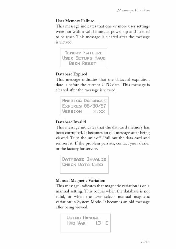
User Memory FailureThis message indicates that one or more user settings
were not within valid limits at power-up and needed
to be reset. This message is cleared after the message
is viewed.
Memory Failure
User Setups Have
Been Reset
Database ExpiredThis message indicates that the datacard expiration
date is before the current UTC date. This message is
cleared after the message is viewed.
America Database
Expires 06/30/97
Version: x.xx
Database InvalidThis message indicates that the datacard memory has
been corrupted. It becomes an old message after being
viewed. Turn the unit off. Pull out the data card and
reinsert it. If the problem persists, contact your dealer
or the factory for service.
Database Invalid
Check Data Card
Manual Magnetic VariationThis message indicates that magnetic variation is on a
manual setting. This occurs when the database is not
valid, or when the user selects manual magnetic
variation in System Mode. It becomes an old message
after being viewed.
Using Manual
Mag Var: 130 E
8-13
Message Function
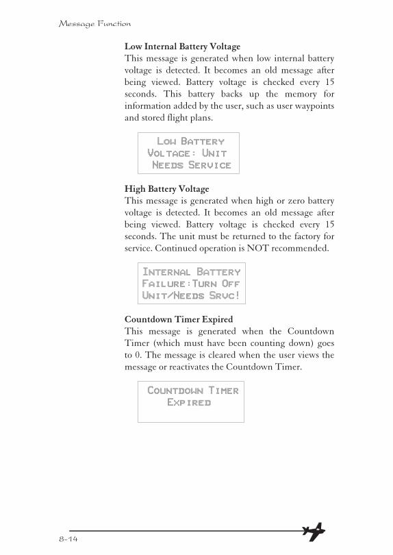
Low Internal Battery VoltageThis message is generated when low internal battery
voltage is detected. It becomes an old message after
being viewed. Battery voltage is checked every 15
seconds. This battery backs up the memory for
information added by the user, such as user waypoints
and stored flight plans.
Low Battery
Voltage: Unit
Needs Service
High Battery VoltageThis message is generated when high or zero battery
voltage is detected. It becomes an old message after
being viewed. Battery voltage is checked every 15
seconds. The unit must be returned to the factory for
service. Continued operation is NOT recommended.
Internal Battery
Failure:Turn Off
Unit/Needs Srvc!
Countdown Timer ExpiredThis message is generated when the Countdown
Timer (which must have been counting down) goes
to 0. The message is cleared when the user views the
message or reactivates the Countdown Timer.
Countdown Timer
Expired
8-14
Message Function
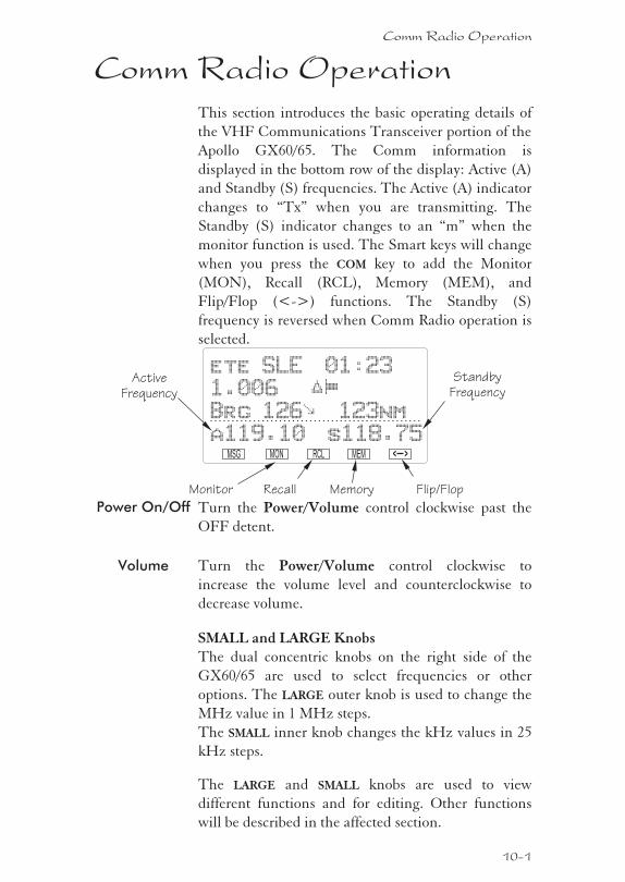
Comm Radio OperationThis section introduces the basic operating details of
the VHF Communications Transceiver portion of the
Apollo GX60/65. The Comm information is
displayed in the bottom row of the display: Active (A)
and Standby (S) frequencies. The Active (A) indicator
changes to “Tx” when you are transmitting. The
Standby (S) indicator changes to an “m” when the
monitor function is used. The Smart keys will change
when you press the COM key to add the Monitor
(MON), Recall (RCL), Memory (MEM), and
Flip/Flop (<->) functions. The Standby (S)
frequency is reversed when Comm Radio operation is
selected.
Power On/Off Turn the Power/Volume control clockwise past the
OFF detent.
Volume Turn the Power/Volume control clockwise to
increase the volume level and counterclockwise to
decrease volume.
SMALL and LARGE KnobsThe dual concentric knobs on the right side of the
GX60/65 are used to select frequencies or other
options. The LARGE outer knob is used to change the
MHz value in 1 MHz steps.
The SMALL inner knob changes the kHz values in 25
kHz steps.
The LARGE and SMALL knobs are used to view
different functions and for editing. Other functions
will be described in the affected section.
Comm Radio Operation
10-1
MEMRCLMONMSG
ete SLE 01:23
1.006
Brg 126 123nm
a119.10 s118.75
һ
±
< >
Monitor Recall Memory Flip/Flop
Active
Frequency
Standby
Frequency
SelectingFrequencies
New frequencies are first selected as a Standby
frequency and then toggled to the Active side when
desired. While viewing the frequency display, use the
LARGE and SMALL knobs on the right side of the
GX60/65 to select the desired frequency. The Standby
frequency is highlighted (reversed).
1. Press COM to reach the Comm radio function. The
Smart keys will change to show the Comm
functions.
2. Turn the LARGE knob to change the Standby
frequency values in one MHz increments. The
MHz selection range is between 118 and 136 in one
MHz steps.
2. Turn the SMALL knob to change the Standby
frequency values in 25 kHz increments. The kHz
selection range is between 000 and 975 kHz in 25
kHz steps. Note that only two digits are displayed
to the right of the decimal point.
Turn the LARGE and SMALL knobs clockwise to
increase and counterclockwise to decrease the
frequency values. Standby frequency selection is not
inhibited during transmit.
Press the FLIP/FLOP key (internal or external) to
toggle the Standby or recalled frequency to the Active
frequency.
10-2
Comm Radio Operation
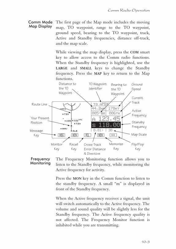
Comm ModeMap Display
The first page of the Map mode includes the moving
map, TO waypoint, range to the TO waypoint,
ground speed, bearing to the TO waypoint, track,
Active and Standby frequencies, distance off-track,
and the map scale.
While viewing the map display, press the COM smart
key to allow access to the Comm radio functions.
When the Standby frequency is highlighted, use the
LARGE and SMALL keys to change the Standby
frequency. Press the MAP key to return to the Map
functions.
FrequencyMonitoring
The Frequency Monitoring function allows you to
listen to the Standby frequency, while monitoring the
Active frequency for activity.
Press the MON key in the Comm function to listen to
the standby frequency. A small “m” is displayed in
front of the Standby frequency.
When the Active frequency receives a signal, the unit
will switch automatically to the Active frequency. The
volume and sound quality will be slightly less for the
Standby frequency. The Active frequency quality is
not affected. The Frequency Monitor function is
inhibited while you are transmitting.
10-3
Comm Radio Operation
MSG
to aPDX
44.2nm
a 123.45
170kt
s 118.00
005 br 006tk½
0.01> 30
MON RCL MEM < >–
TO Waypoint
Identifier
Cross Track
Error Distance
& Direction
Bearing to
the TO
Waypoint
Distance to
the TO
Waypoint
Ground
Speed
Current
Track
Map Scale
Route Line
Your Present
Position
Active
Frequency
Standby
Frequency
Flip/Flop
Key
Memorize
Key
Monitor
Key
Message
Key
Recall
Key
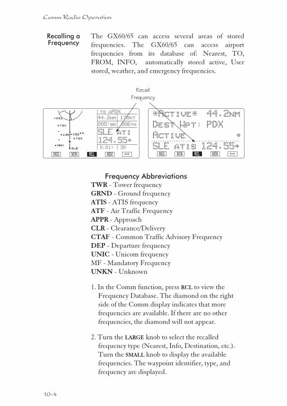
Recalling aFrequency
The GX60/65 can access several areas of stored
frequencies. The GX60/65 can access airport
frequencies from its database of: Nearest, TO,
FROM, INFO, automatically stored active, User
stored, weather, and emergency frequencies.
Frequency AbbreviationsTWR - Tower frequency
GRND - Ground frequency
ATIS - ATIS frequency
ATF - Air Traffic Frequency
APPR - Approach
CLR - Clearance/Delivery
CTAF - Common Traffic Advisory Frequency
DEP - Departure frequency
UNIC - Unicom frequency
MF - Mandatory Frequency
UNKN - Unknown
1. In the Comm function, press RCL to view the
Frequency Database. The diamond on the right
side of the Comm display indicates that more
frequencies are available. If there are no other
frequencies, the diamond will not appear.
2. Turn the LARGE knob to select the recalled
frequency type (Nearest, Info, Destination, etc.).
Turn the SMALL knob to display the available
frequencies. The waypoint identifier, type, and
frequency are displayed.
10-4
Comm Radio Operation
Recall
Frequency
to aPDX
44.2nm
SLE ati
170kt
005 br 006tk½
0.01> 30
MSG MON RCL MEM < >–
124.55·
*Active* 44.2nm
Dest Wpt: PDX
Active ·
SLE atis 124.55·MSG MON RCL MEM < >–
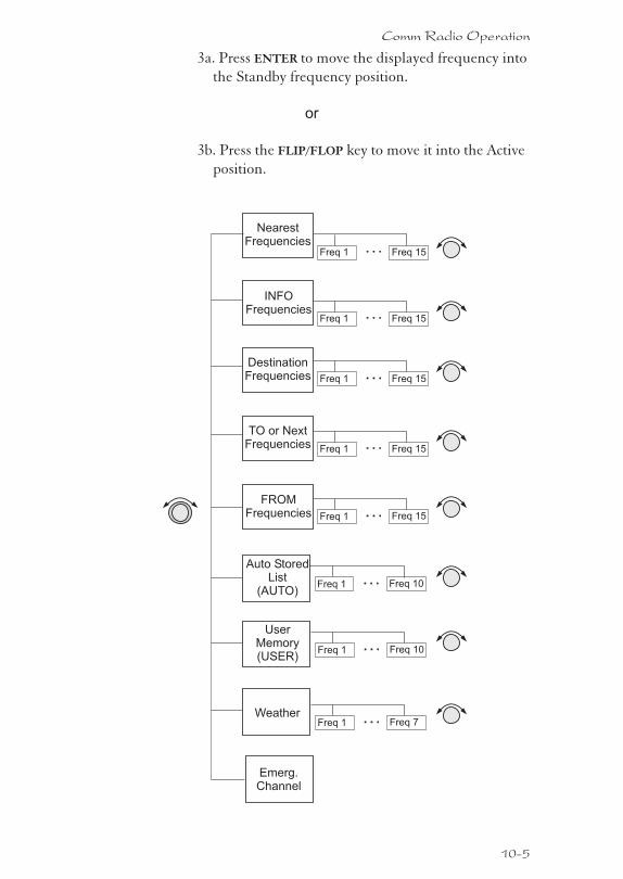
3a. Press ENTER to move the displayed frequency into
the Standby frequency position.
or
3b. Press the FLIP/FLOP key to move it into the Active
position.
10-5
Comm Radio Operation
Auto StoredList
(AUTO)
TO or NextFrequencies
FROMFrequencies
INFOFrequencies
Freq 1 Freq 15
Freq 1 Freq 15
UserMemory(USER)
Freq 1 Freq 10
Freq 1 Freq 10
Weather
Emerg.Channel
Freq 1 Freq 7
Freq 1 Freq 15
DestinationFrequencies
Freq 1 Freq 15
NearestFrequencies
Freq 1 Freq 15
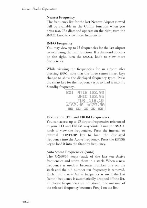
Nearest FrequencyThe frequency list for the last Nearest Airport viewed
will be available in the Comm function when you
press RCL. If a diamond appears on the right, turn the
SMALL knob to view more frequencies.
INFO FrequencyYou may view up to 15 frequencies for the last airport
viewed using the Info function. If a diamond appears
on the right, turn the SMALL knob to view more
frequencies.
While viewing the frequencies for an airport after
pressing INFO, note that the three center smart keys
change to show the displayed frequency types. Press
the smart key for the frequency type to load it into the
Standby frequency.
Destination, TO, and FROM FrequenciesYou can access up to 15 airport frequencies referenced
to your TO and FROM waypoints. Turn the SMALL
knob to view the frequencies. Press the internal or
external FLIP/FLOP key to load the displayed
frequency into the Active frequency. Press the ENTER
key to load it into the Standby frequency.
Auto Stored Frequencies (Auto)The GX60/65 keeps track of the last ten Active
frequencies and stores them in a stack. When a new
frequency is used, it becomes number one on the
stack and the old number ten frequency is removed.
Each time a new Active frequency is used, the last
(tenth) frequency is automatically dropped off the list.
Duplicate frequencies are not stored; one instance of
the selected frequency becomes Freq 1 on the list.
10-6
Comm Radio Operation
TWRUNIATIMSG COM
BOI ATIS 123.90
a162.40 s123.90
UNIC 122.95
TWR 118.10
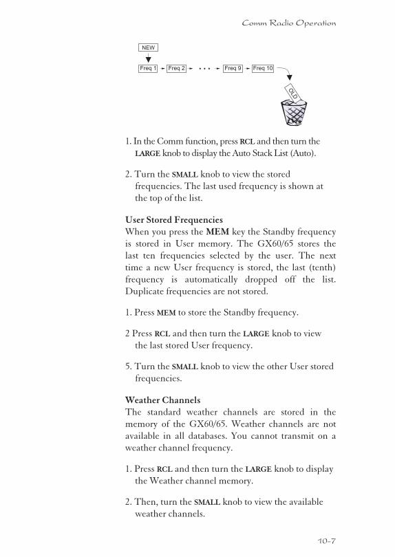
1. In the Comm function, press RCL and then turn the
LARGE knob to display the Auto Stack List (Auto).
2. Turn the SMALL knob to view the stored
frequencies. The last used frequency is shown at
the top of the list.
User Stored FrequenciesWhen you press the MEM key the Standby frequency
is stored in User memory. The GX60/65 stores the
last ten frequencies selected by the user. The next
time a new User frequency is stored, the last (tenth)
frequency is automatically dropped off the list.
Duplicate frequencies are not stored.
1. Press MEM to store the Standby frequency.
2 Press RCL and then turn the LARGE knob to view
the last stored User frequency.
5. Turn the SMALL knob to view the other User stored
frequencies.
Weather ChannelsThe standard weather channels are stored in the
memory of the GX60/65. Weather channels are not
available in all databases. You cannot transmit on a
weather channel frequency.
1. Press RCL and then turn the LARGE knob to display
the Weather channel memory.
2. Then, turn the SMALL knob to view the available
weather channels.
10-7
Comm Radio Operation
Freq 1 Freq 2 Freq 9 Freq 10
NEW
OLD
Weather Frequencies(When available)
162.400 MHz
162.425 MHz
162.450 MHz
162.475 MHz
162.500 MHz
162.525 MHz
162.550 MHz
Note
You can search for the best local weather by
inserting a Weather frequency into the
Standby position, pressing MON, and then
turning the SMALL knob to scroll through
the Weather channel choices.
Emergency ChannelThe standard emergency channel (121.50 MHz) is
stored in the memory of the GX60/65.
1. In the Comm function, press RCL and then turn the
LARGE knob to display the Emergency channel
memory.
2. Press the FLIP/FLOP key to load the Emergency
Channel into the Active frequency or press ENTER
to load it into the Standby frequency.
IntercomFunction
When two headphone and microphone jacks are
connected to the GX60/65, these headsets can be used
as a voice-activated intercom.
When you select the Intercom function with the
installed selector switch, the intercom function is
enabled. The Volume control will control the
headphone listening level. The receive function will
automatically become active when a signal is detected.
Receiver audio volume will be reduced when the
intercom is selected.
The Intercom Squelch Sensitivity can be set in theSystem Functions on page 10.
10-8
Comm Radio Operation
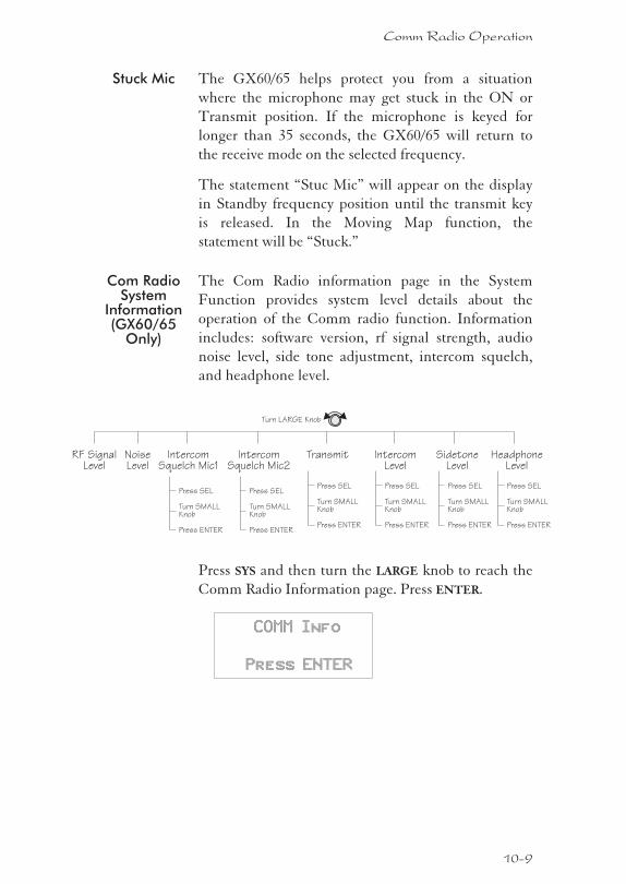
Stuck Mic The GX60/65 helps protect you from a situation
where the microphone may get stuck in the ON or
Transmit position. If the microphone is keyed for
longer than 35 seconds, the GX60/65 will return to
the receive mode on the selected frequency.
The statement “Stuc Mic” will appear on the display
in Standby frequency position until the transmit key
is released. In the Moving Map function, the
statement will be “Stuck.”
Com RadioSystem
Information(GX60/65
Only)
The Com Radio information page in the System
Function provides system level details about the
operation of the Comm radio function. Information
includes: software version, rf signal strength, audio
noise level, side tone adjustment, intercom squelch,
and headphone level.
Press SYS and then turn the LARGE knob to reach the
Comm Radio Information page. Press ENTER.
COMM Info
Press ENTER
10-9
Comm Radio Operation
RF SignalLevel
NoiseLevel
IntercomLevel
SidetoneLevel
Turn LARGE Knob
HeadphoneLevel
IntercomSquelch Mic1
Press SEL
Turn SMALLKnob
Press ENTER
Press SEL
Turn SMALLKnob
Press ENTER
Press SEL
Turn SMALLKnob
Press ENTER
Press SEL
Turn SMALLKnob
Press ENTER
Transmit
Press SEL
Turn SMALLKnob
Press ENTER
IntercomSquelch Mic2
Press SEL
Turn SMALLKnob
Press ENTER
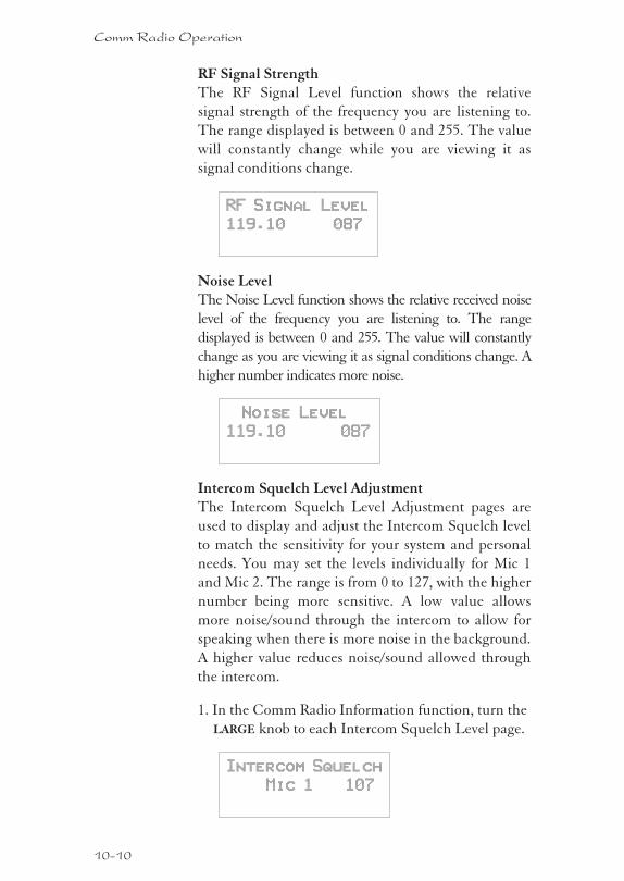
RF Signal StrengthThe RF Signal Level function shows the relative
signal strength of the frequency you are listening to.
The range displayed is between 0 and 255. The value
will constantly change while you are viewing it as
signal conditions change.
RF Signal Level
119.10 087
Noise LevelThe Noise Level function shows the relative received noise
level of the frequency you are listening to. The range
displayed is between 0 and 255. The value will constantly
change as you are viewing it as signal conditions change. A
higher number indicates more noise.
Noise Level
119.10 087
Intercom Squelch Level AdjustmentThe Intercom Squelch Level Adjustment pages are
used to display and adjust the Intercom Squelch level
to match the sensitivity for your system and personal
needs. You may set the levels individually for Mic 1
and Mic 2. The range is from 0 to 127, with the higher
number being more sensitive. A low value allows
more noise/sound through the intercom to allow for
speaking when there is more noise in the background.
A higher value reduces noise/sound allowed through
the intercom.
1. In the Comm Radio Information function, turn the
LARGE knob to each Intercom Squelch Level page.
Intercom Squelch
Mic 1 107
10-10
Comm Radio Operation
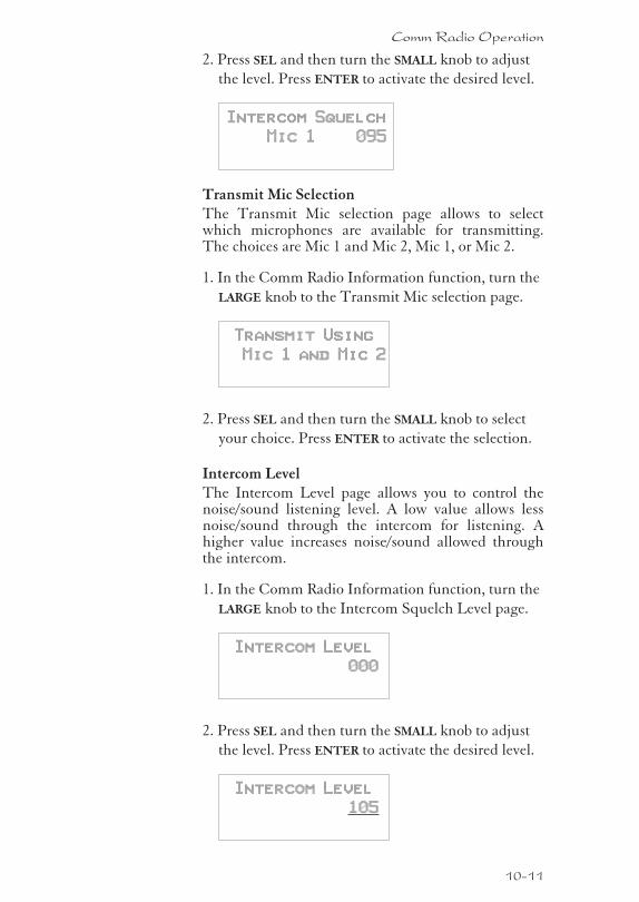
2. Press SEL and then turn the SMALL knob to adjust
the level. Press ENTER to activate the desired level.
Intercom Squelch
Mic 1 095
Transmit Mic SelectionThe Transmit Mic selection page allows to selectwhich microphones are available for transmitting.The choices are Mic 1 and Mic 2, Mic 1, or Mic 2.
1. In the Comm Radio Information function, turn the
LARGE knob to the Transmit Mic selection page.
Transmit Using
Mic 1 and Mic 2
2. Press SEL and then turn the SMALL knob to select
your choice. Press ENTER to activate the selection.
Intercom LevelThe Intercom Level page allows you to control thenoise/sound listening level. A low value allows lessnoise/sound through the intercom for listening. Ahigher value increases noise/sound allowed throughthe intercom.
1. In the Comm Radio Information function, turn the
LARGE knob to the Intercom Squelch Level page.
Intercom Level
000
2. Press SEL and then turn the SMALL knob to adjust
the level. Press ENTER to activate the desired level.
Intercom Level
105
10-11
Comm Radio Operation
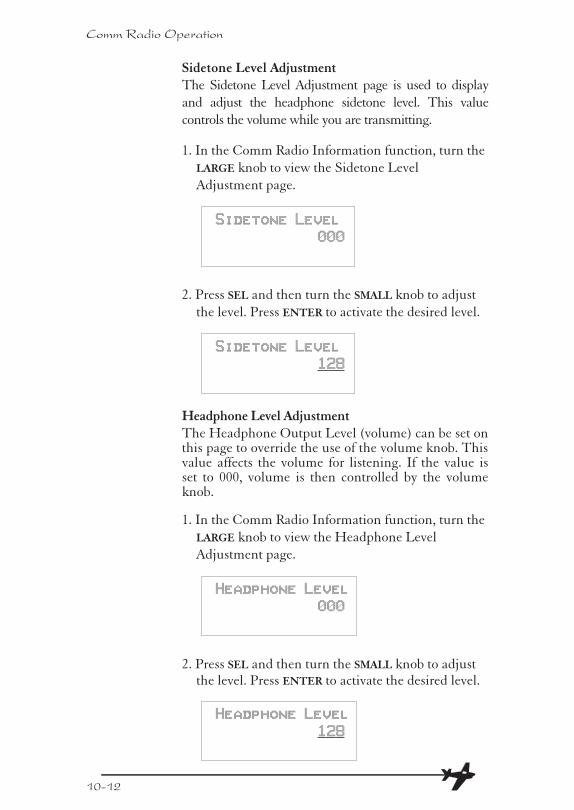
Sidetone Level AdjustmentThe Sidetone Level Adjustment page is used to display
and adjust the headphone sidetone level. This value
controls the volume while you are transmitting.
1. In the Comm Radio Information function, turn the
LARGE knob to view the Sidetone Level
Adjustment page.
Sidetone Level
000
2. Press SEL and then turn the SMALL knob to adjust
the level. Press ENTER to activate the desired level.
Sidetone Level
128
Headphone Level AdjustmentThe Headphone Output Level (volume) can be set onthis page to override the use of the volume knob. Thisvalue affects the volume for listening. If the value isset to 000, volume is then controlled by the volumeknob.
1. In the Comm Radio Information function, turn the
LARGE knob to view the Headphone Level
Adjustment page.
Headphone Level
000
2. Press SEL and then turn the SMALL knob to adjustthe level. Press ENTER to activate the desired level.
Headphone Level
128
10-12
Comm Radio Operation
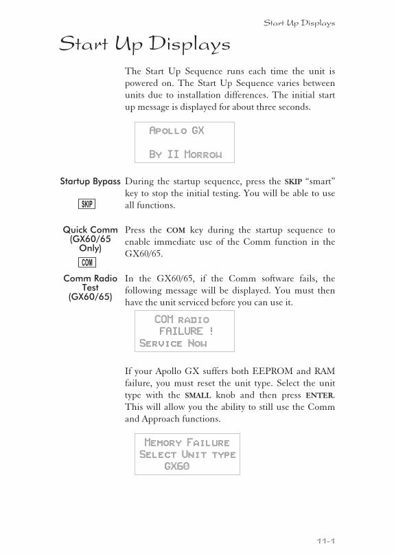
Start Up DisplaysThe Start Up Sequence runs each time the unit is
powered on. The Start Up Sequence varies between
units due to installation differences. The initial start
up message is displayed for about three seconds.
Apollo GX
By II Morrow
Startup Bypass During the startup sequence, press the SKIP “smart”
key to stop the initial testing. You will be able to use
all functions.
Quick Comm(GX60/65
Only)
Press the COM key during the startup sequence to
enable immediate use of the Comm function in the
GX60/65.
Comm RadioTest
(GX60/65)
In the GX60/65, if the Comm software fails, the
following message will be displayed. You must then
have the unit serviced before you can use it.
COM radio
FAILURE !
Service Now
If your Apollo GX suffers both EEPROM and RAM
failure, you must reset the unit type. Select the unit
type with the SMALL knob and then press ENTER.
This will allow you the ability to still use the Comm
and Approach functions.
Memory Failure
Select Unit type
GX60
Start Up Displays
11-1
SKIP
COM
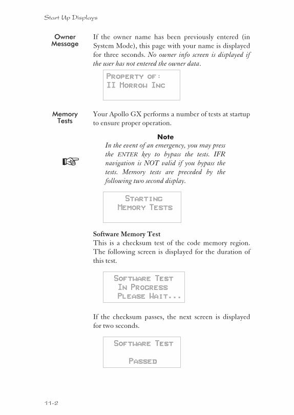
OwnerMessage
If the owner name has been previously entered (in
System Mode), this page with your name is displayed
for three seconds. No owner info screen is displayed if
the user has not entered the owner data.
Property of:
II Morrow Inc
MemoryTests
Your Apollo GX performs a number of tests at startup
to ensure proper operation.
Note
In the event of an emergency, you may press
the ENTER key to bypass the tests. IFR
navigation is NOT valid if you bypass the
tests. Memory tests are preceded by the
following two second display.
Starting
Memory Tests
Software Memory TestThis is a checksum test of the code memory region.
The following screen is displayed for the duration of
this test.
Software Test
In Progress
Please Wait...
If the checksum passes, the next screen is displayed
for two seconds.
Software Test
Passed
11-2
Start Up Displays
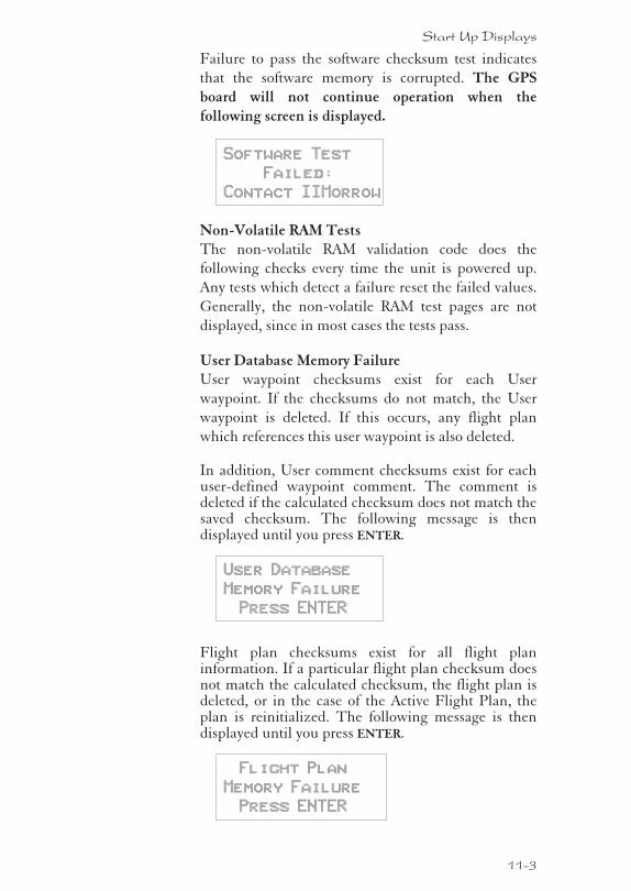
Failure to pass the software checksum test indicates
that the software memory is corrupted. The GPS
board will not continue operation when the
following screen is displayed.
Software Test
Failed:
Contact IIMorrow
Non-Volatile RAM TestsThe non-volatile RAM validation code does the
following checks every time the unit is powered up.
Any tests which detect a failure reset the failed values.
Generally, the non-volatile RAM test pages are not
displayed, since in most cases the tests pass.
User Database Memory FailureUser waypoint checksums exist for each User
waypoint. If the checksums do not match, the User
waypoint is deleted. If this occurs, any flight plan
which references this user waypoint is also deleted.
In addition, User comment checksums exist for eachuser-defined waypoint comment. The comment isdeleted if the calculated checksum does not match thesaved checksum. The following message is thendisplayed until you press ENTER.
User Database
Memory Failure
Press ENTER
Flight plan checksums exist for all flight planinformation. If a particular flight plan checksum doesnot match the calculated checksum, the flight plan isdeleted, or in the case of the Active Flight Plan, theplan is reinitialized. The following message is thendisplayed until you press ENTER.
Flight Plan
Memory Failure
Press ENTER
11-3
Start Up Displays
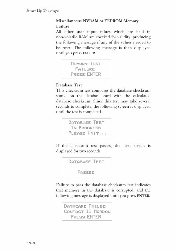
Miscellaneous NVRAM or EEPROM Memory
FailureAll other user input values which are held in
non-volatile RAM are checked for validity, producing
the following message if any of the values needed to
be reset. The following message is then displayed
until you press ENTER.
Memory Test
Failure
Press ENTER
Database TestThis checksum test compares the database checksum
stored on the database card with the calculated
database checksum. Since this test may take several
seconds to complete, the following screen is displayed
until the test is completed.
Database Test
In Progress
Please Wait...
If the checksum test passes, the next screen is
displayed for two seconds.
Database Test
Passed
Failure to pass the database checksum test indicates
that memory in the database is corrupted, and the
following message is displayed until you press ENTER.
Datacard Failed
Contact II Morrow
Press ENTER
11-4
Start Up Displays
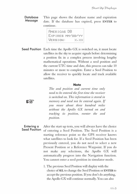
DatabaseMessage
This page shows the database name and expiration
date. If the database has expired, press ENTER to
continue.
Americas DB
Expires mm/dd/yy
Version: x.xx
Seed Position Each time the Apollo GX is switched on, it must locate
satellites in the sky to acquire signals before determining
a position fix in a complex process involving lengthy
mathematical operations. Without a seed position and
the current UTC time and date, this process can take 10
minutes or more to complete. Enter a Seed Position to
allow the receiver to quickly locate and track available
satellites.
Note
The seed position and current time only
need to be entered the first time the receiver
is switched on. This information is stored in
memory and need not be entered again. If
you move about three hundred miles
without the Apollo GX turned on and
tracking its position, reenter the seed
position.
Entering aSeed Position
After the start up tests, you will always have the choice
of entering a Seed Position. The Seed Position is a
starting reference point so the GPS receiver knows
what satellites to look for. If a Seed Position has been
previously entered, you do not need to select a new
Present Position or a Reference Waypoint. If you do
not make any selections, the Apollo GX will
automatically progress into the Navigation function.
You cannot enter a seed position in simulator mode.
1. The previous Seed Position will display with the
choice of SEL to change the Seed Position or ENTER to
accept the previous position. If you don’t do anything,
the Apollo GX will continue normally. You can also
11-5
Start Up Displays
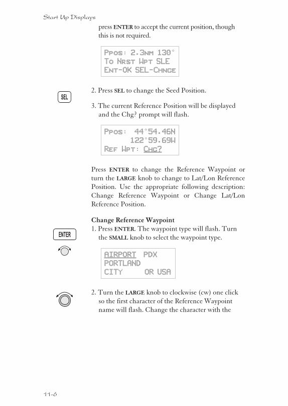
press ENTER to accept the current position, though
this is not required.
Ppos: 2.3nm 130°
To Nrst Wpt SLE
Ent-OK SEL-Chnge
2. Press SEL to change the Seed Position.
3. The current Reference Position will be displayed
and the Chg? prompt will flash.
Ppos: 44°54.46N
122°59.69W
Ref Wpt: Chg?
Press ENTER to change the Reference Waypoint or
turn the LARGE knob to change to Lat/Lon Reference
Position. Use the appropriate following description:
Change Reference Waypoint or Change Lat/Lon
Reference Position.
Change Reference Waypoint1. Press ENTER. The waypoint type will flash. Turn
the SMALL knob to select the waypoint type.
AIRPORT PDX
PORTLAND
CITY OR USA
2. Turn the LARGE knob to clockwise (cw) one click
so the first character of the Reference Waypoint
name will flash. Change the character with the
11-6
Start Up Displays
ENTER
SEL
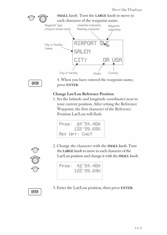
SMALL knob. Turn the LARGE knob to move to
each character of the waypoint name.
4. When you have entered the waypoint name,
press ENTER.
Change Lat/Lon Reference Position1. Set the latitude and longitude coordinates near to
your current position. After setting the Reference
Waypoint, the first character of the Reference
Position Lat/Lon will flash.
Ppos: 44°54.46N
122°59.69W
Ref Wpt: Chg?
2. Change the character with the SMALL knob. Turn
the LARGE knob to move to each character of the
Lat/Lon position and change it with the SMALL knob.
Ppos: 44°54.46N
122°59.69W
3. Enter the Lat/Lon position, then press ENTER.
11-7
Start Up Displays
ENTER
ENTER
AIRPORT
SALEM
CITY OR USA
SLE
Waypoint Type
(Airport shown here)Waypoint
Indentifier
Underline indicates
flashing character
City or Facility
City or Facility
Name
State Country
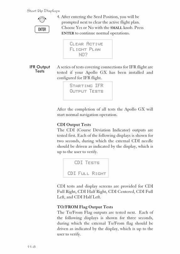
4. After entering the Seed Position, you will be
prompted next to clear the active flight plan.
Choose Yes or No with the SMALL knob. Press
ENTER to continue normal operations.
Clear Active
Flight Plan
NO?
IFR OutputTests
A series of tests covering connections for IFR flight are
tested if your Apollo GX has been installed and
configured for IFR flight.
Starting IFR
Output Tests
After the completion of all tests the Apollo GX will
start normal navigation operation.
CDI Output TestsThe CDI (Course Deviation Indicator) outputs are
tested first. Each of the following displays is shown for
two seconds, during which the external CDI needle
should be driven as indicated by the display, which is
up to the user to verify.
CDI Tests
CDI Full Right
CDI tests and display screens are provided for CDI
Full Right, CDI Half Right, CDI Centered, CDI Full
Left, and CDI Half Left.
TO/FROM Flag Output TestsThe To/From Flag outputs are tested next. Each of
the following displays is shown for three seconds,
during which the external To/From flag should be
driven as indicated by the display, which is up to the
user to verify.
11-8
Start Up Displays
ENTER
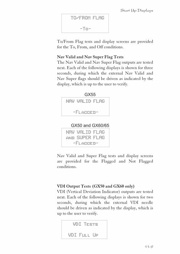
TO/FROM FLAG
-To-
To/From Flag tests and display screens are provided
for the To, From, and Off conditions.
Nav Valid and Nav Super Flag TestsThe Nav Valid and Nav Super Flag outputs are tested
next. Each of the following displays is shown for three
seconds, during which the external Nav Valid and
Nav Super flags should be driven as indicated by the
display, which is up to the user to verify.
GX55
NAV VALID FLAG
-Flagged-
GX50 and GX60/65
NAV VALID FLAG
and SUPER FLAG
-Flagged-
Nav Valid and Super Flag tests and display screens
are provided for the Flagged and Not Flagged
conditions.
VDI Output Tests (GX50 and GX60 only)VDI (Vertical Deviation Indicator) outputs are tested
next. Each of the following displays is shown for two
seconds, during which the external VDI needle
should be driven as indicated by the display, which is
up to the user to verify.
VDI Tests
VDI Full Up
11-9
Start Up Displays
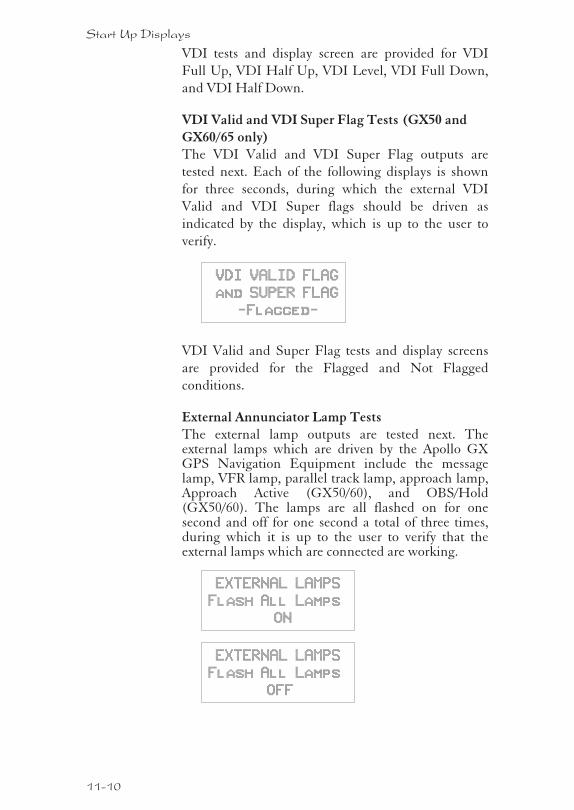
VDI tests and display screen are provided for VDI
Full Up, VDI Half Up, VDI Level, VDI Full Down,
and VDI Half Down.
VDI Valid and VDI Super Flag Tests (GX50 and
GX60/65 only)The VDI Valid and VDI Super Flag outputs are
tested next. Each of the following displays is shown
for three seconds, during which the external VDI
Valid and VDI Super flags should be driven as
indicated by the display, which is up to the user to
verify.
VDI VALID FLAG
and SUPER FLAG
-Flagged-
VDI Valid and Super Flag tests and display screens
are provided for the Flagged and Not Flagged
conditions.
External Annunciator Lamp TestsThe external lamp outputs are tested next. Theexternal lamps which are driven by the Apollo GXGPS Navigation Equipment include the messagelamp, VFR lamp, parallel track lamp, approach lamp,Approach Active (GX50/60), and OBS/Hold(GX50/60). The lamps are all flashed on for onesecond and off for one second a total of three times,during which it is up to the user to verify that theexternal lamps which are connected are working.
EXTERNAL LAMPS
Flash All Lamps
ON
EXTERNAL LAMPS
Flash All Lamps
OFF
11-10
Start Up Displays
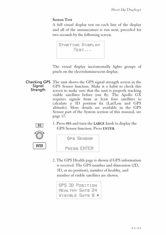
Screen TestA full visual display test on each line of the display
and all of the annunciators is run next, preceded for
two seconds by the following screen.
Starting Display
Test...
The visual display incrementally lights groups of
pixels on the electroluminescent display.
Checking GPSSignal
Strength
The unit shows the GPS signal strength screen in theGPS Sensor function. Make it a habit to check thisscreen to make sure that the unit is properly trackingvisible satellites before you fly. The Apollo GXrequires signals from at least four satellites tocalculate a 3D position fix (Lat/Lon and GPSaltitude). More details are available in the GPSSensor part of the System section of this manual, seepage 17.
1. Press SYS and turn the LARGE knob to display the
GPS Sensor function. Press ENTER.
Gps Sensor
Press ENTER
2. The GPS Health page is shown if GPS information
is received. The GPS number and dimension (2D,
3D, or no position), number of healthy, and
number of visible satellites are shown.
GPS 3D Position
Healthy Sats 24
Visible Sats 8 Y
11-11
Start Up Displays
ENTER
SYS
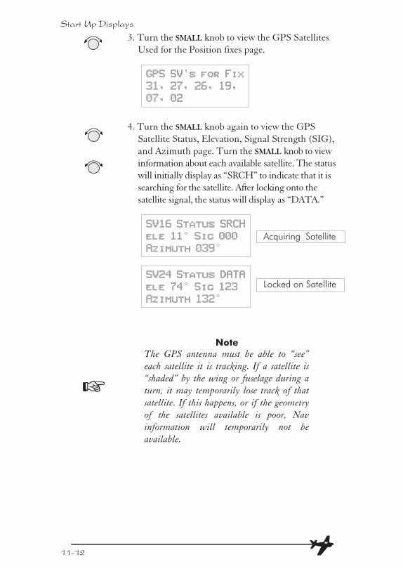
3. Turn the SMALL knob to view the GPS Satellites
Used for the Position fixes page.
GPS SV’s for Fix
31, 27, 26, 19,
07, 02
4. Turn the SMALL knob again to view the GPS
Satellite Status, Elevation, Signal Strength (SIG),
and Azimuth page. Turn the SMALL knob to view
information about each available satellite. The status
will initially display as “SRCH” to indicate that it is
searching for the satellite. After locking onto the
satellite signal, the status will display as “DATA.”
SV16 Status SRCH
ele 11° Sig 000
Azimuth 039°
SV24 Status DATA
ele 74° Sig 123
Azimuth 132°
Note
The GPS antenna must be able to “see”
each satellite it is tracking. If a satellite is
“shaded” by the wing or fuselage during a
turn, it may temporarily lose track of that
satellite. If this happens, or if the geometry
of the satellites available is poor, Nav
information will temporarily not be
available.
11-12
Start Up Displays
Acquiring Satellite
Locked on Satellite
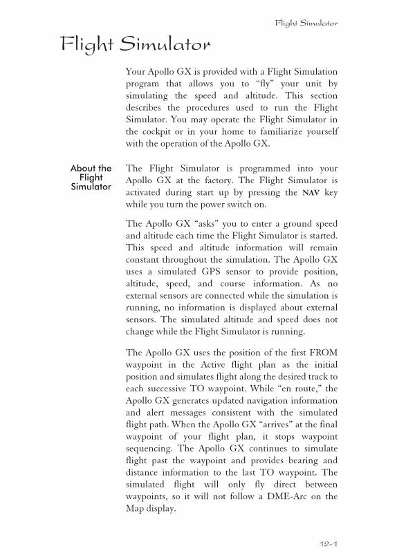
Flight SimulatorYour Apollo GX is provided with a Flight Simulation
program that allows you to “fly” your unit by
simulating the speed and altitude. This section
describes the procedures used to run the Flight
Simulator. You may operate the Flight Simulator in
the cockpit or in your home to familiarize yourself
with the operation of the Apollo GX.
About theFlight
Simulator
The Flight Simulator is programmed into your
Apollo GX at the factory. The Flight Simulator is
activated during start up by pressing the NAV key
while you turn the power switch on.
The Apollo GX “asks” you to enter a ground speed
and altitude each time the Flight Simulator is started.
This speed and altitude information will remain
constant throughout the simulation. The Apollo GX
uses a simulated GPS sensor to provide position,
altitude, speed, and course information. As no
external sensors are connected while the simulation is
running, no information is displayed about external
sensors. The simulated altitude and speed does not
change while the Flight Simulator is running.
The Apollo GX uses the position of the first FROM
waypoint in the Active flight plan as the initial
position and simulates flight along the desired track to
each successive TO waypoint. While “en route,” the
Apollo GX generates updated navigation information
and alert messages consistent with the simulated
flight path. When the Apollo GX “arrives” at the final
waypoint of your flight plan, it stops waypoint
sequencing. The Apollo GX continues to simulate
flight past the waypoint and provides bearing and
distance information to the last TO waypoint. The
simulated flight will only fly direct between
waypoints, so it will not follow a DME-Arc on the
Map display.
Flight Simulator
12-1
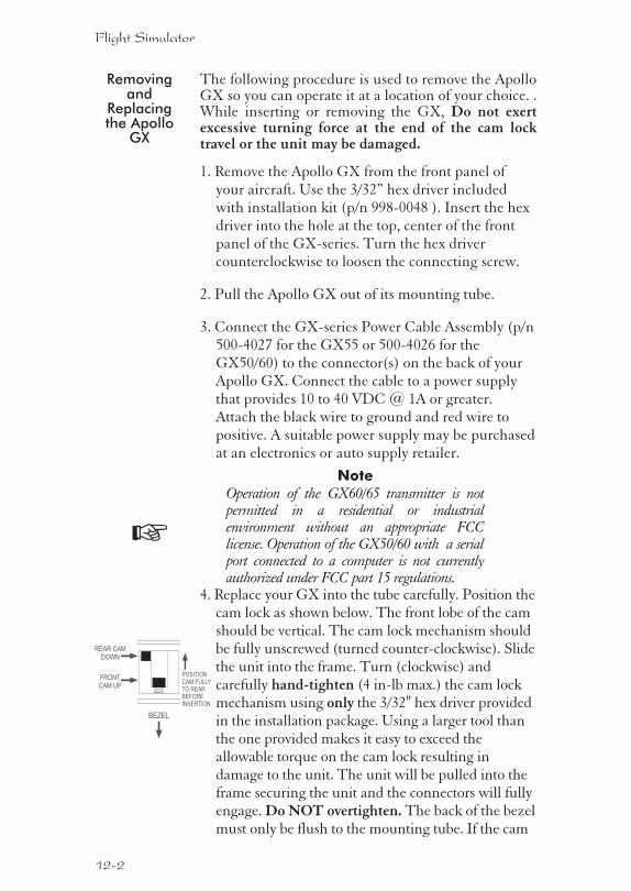
Removingand
Replacingthe Apollo
GX
The following procedure is used to remove the ApolloGX so you can operate it at a location of your choice. .While inserting or removing the GX, Do not exertexcessive turning force at the end of the cam locktravel or the unit may be damaged.
1. Remove the Apollo GX from the front panel ofyour aircraft. Use the 3/32” hex driver includedwith installation kit (p/n 998-0048 ). Insert the hexdriver into the hole at the top, center of the frontpanel of the GX-series. Turn the hex drivercounterclockwise to loosen the connecting screw.
2. Pull the Apollo GX out of its mounting tube.
3. Connect the GX-series Power Cable Assembly (p/n500-4027 for the GX55 or 500-4026 for theGX50/60) to the connector(s) on the back of yourApollo GX. Connect the cable to a power supplythat provides 10 to 40 VDC @ 1A or greater.Attach the black wire to ground and red wire topositive. A suitable power supply may be purchasedat an electronics or auto supply retailer.
Note
Operation of the GX60/65 transmitter is notpermitted in a residential or industrialenvironment without an appropriate FCClicense. Operation of the GX50/60 with a serialport connected to a computer is not currentlyauthorized under FCC part 15 regulations.
4. Replace your GX into the tube carefully. Position thecam lock as shown below. The front lobe of the camshould be vertical. The cam lock mechanism shouldbe fully unscrewed (turned counter-clockwise). Slidethe unit into the frame. Turn (clockwise) andcarefully hand-tighten (4 in-lb max.) the cam lockmechanism using only the 3/32" hex driver providedin the installation package. Using a larger tool thanthe one provided makes it easy to exceed theallowable torque on the cam lock resulting indamage to the unit. The unit will be pulled into theframe securing the unit and the connectors will fullyengage. Do NOT overtighten. The back of the bezelmust only be flush to the mounting tube. If the cam
12-2
Flight Simulator
BEZEL
FRONTCAM UP
REAR CAMDOWN
POSITIONCAM FULLYTO REARBEFOREINSERTION
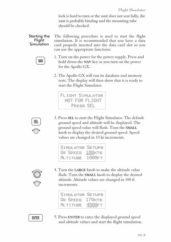
lock is hard to turn or the unit does not seat fully, theunit is probably binding and the mounting tubeshould be checked.
Starting theFlight
Simulation
The following procedure is used to start the flightsimulation. It is recommended that you have a datacard properly inserted into the data card slot so youcan use the appropriate functions.
1. Turn on the power for the power supply. Press andhold down the NAV key as you turn on the powerfor the Apollo GX.
2. The Apollo GX will run its database and memorytests. The display will then show that it is ready tostart the Flight Simulator.
Flight Simulator
NOT FOR FLIGHT
Press SEL
3. Press SEL to start the Flight Simulator. The defaultground speed and altitude will be displayed. Theground speed value will flash. Turn the SMALL
knob to display the desired ground speed. Speedvalues are changed in 10 kt increments.
Simulator Setups
Gr Speed 100kts
Altitude 1000ft
4. Turn the LARGE knob to make the altitude valueflash. Turn the SMALL knob to display the desiredaltitude. Altitude values are changed in 100 ftincrements.
Simulator Setups
Gr Speed 170kts
Altitude 4500ft
5. Press ENTER to enter the displayed ground speedand altitude values and start the flight simulation.
12-3
Flight Simulator
ENTER
SEL
NAV
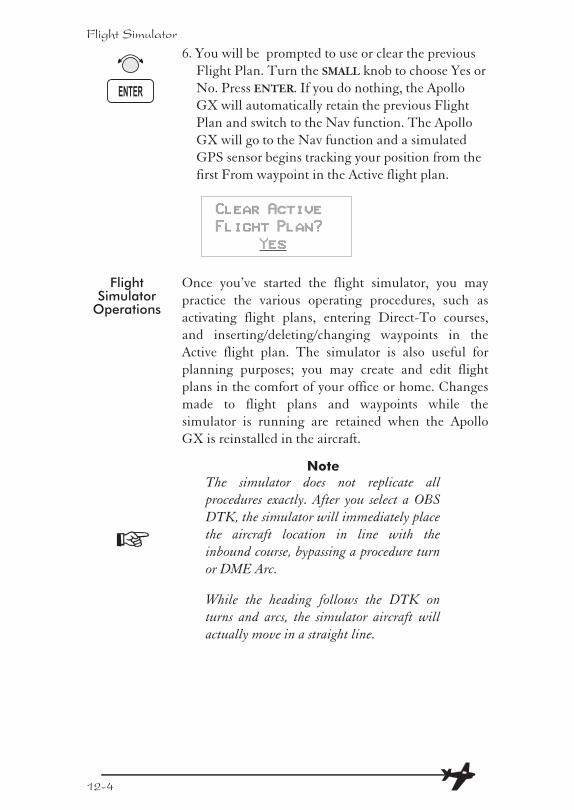
6. You will be prompted to use or clear the previous
Flight Plan. Turn the SMALL knob to choose Yes or
No. Press ENTER. If you do nothing, the Apollo
GX will automatically retain the previous Flight
Plan and switch to the Nav function. The Apollo
GX will go to the Nav function and a simulated
GPS sensor begins tracking your position from the
first From waypoint in the Active flight plan.
Clear Active
Flight Plan?
Yes
FlightSimulator
Operations
Once you’ve started the flight simulator, you may
practice the various operating procedures, such as
activating flight plans, entering Direct-To courses,
and inserting/deleting/changing waypoints in the
Active flight plan. The simulator is also useful for
planning purposes; you may create and edit flight
plans in the comfort of your office or home. Changes
made to flight plans and waypoints while the
simulator is running are retained when the Apollo
GX is reinstalled in the aircraft.
Note
The simulator does not replicate all
procedures exactly. After you select a OBS
DTK, the simulator will immediately place
the aircraft location in line with the
inbound course, bypassing a procedure turn
or DME Arc.
While the heading follows the DTK on
turns and arcs, the simulator aircraft will
actually move in a straight line.
12-4
Flight Simulator
ENTER
TroubleshootingOr, what to do when nothing works!This section contains information to troubleshootyour Apollo GX product when improper operation isobserved. The following table lists possible problemsyou could encounter while operating the unit.Examine the possible causes of the problem and takethe action listed to correct the trouble. If you cannotcorrect the problem, contact your dealer. If yourdealer is unavailable, contact the II Morrow factory atthe address and phone number listed.
Contacting theFactory
If efforts to resolve the problem fail, contact your
dealer or the factory weekdays from 8:00 A.M. until
5:00 P.M. Pacific time for technical assistance. The II
Morrow technical service staff will gladly assist you.
Please have the following information ready:
� System configuration (products, antennas,mounting locations, etc.)
� Model No., part number, and serial number
� Software versions
� Description of the problem
� Efforts made to isolate/solve the problem
� Computed Lat/Lon position shown on yourApollo
� Local time, UTC time, and date
II Morrow Inc.
Technical Service Department
2345 Turner Road S.E.
Salem, OR 97302 U.S.A.
U.S.A. Toll Free 800-525-6726
Canada Toll Free 800-654-3415
FAX (503) 364-2138
International (503) 391-3411
Troubleshooting
13-1
To EnsureTrouble FreeOperation
Avoid high cockpit temperatures when the aircraft is
not in use. Extreme heat shortens the life of any
electronic equipment. Periodically check all antenna,
power, and ground connections.
Caution
DO NOT clean the face plate with
chemical cleaning agents, solvents, or harsh
detergents. A soft cloth may be used to clean
the face plate. DO NOT wax or paint the
antenna.
BatteryReplacement
The Apollo GX memory is maintained by a lithium
battery. The expected service life of this type of battery
is from four to six years. This is not a user replaceable
item. The lithium battery must be replaced by the
factory, an authorized dealer, or service center.
If You HaveA Problem
Please read the instructions again for the desired
function.
If You AreUnable ToCorrect The
Problem
Record as much information as possible, such as
where and when the problem occurred, symptoms,
and your actions. Record the position sensor data
(displayed in SYS mode) for ALL satellites (GPS)
and call your II Morrow dealer, Service Center, or the
factory. The technician MUST have this information
to help you solve the problem.
Problem Possible Cause Action
Unit does not poweron
Open in powersupply circuit
Check circuitbreaker - reset ifnecessary
Faulty electricalwiring orconnection
Contact your dealerto perform electricalsystem test
13-2
Troubleshooting
!
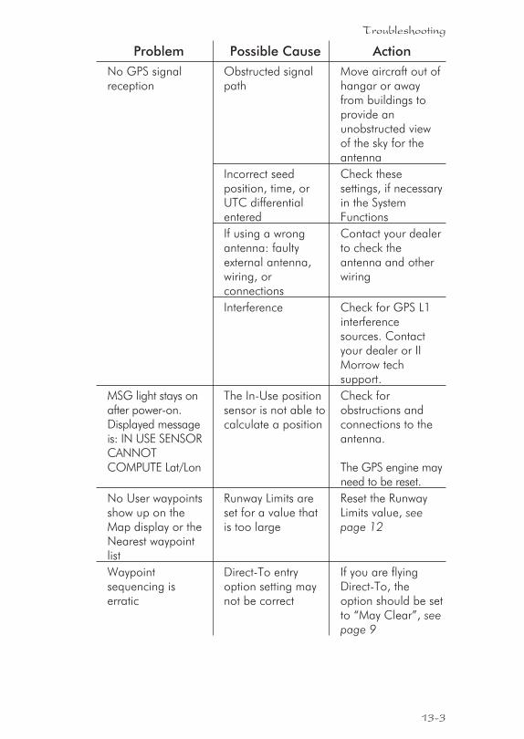
Problem Possible Cause Action
No GPS signalreception
Obstructed signalpath
Move aircraft out ofhangar or awayfrom buildings toprovide anunobstructed viewof the sky for theantenna
Incorrect seedposition, time, orUTC differentialentered
Check thesesettings, if necessaryin the SystemFunctions
If using a wrongantenna: faultyexternal antenna,wiring, orconnections
Contact your dealerto check theantenna and otherwiring
Interference Check for GPS L1interferencesources. Contactyour dealer or IIMorrow techsupport.
MSG light stays onafter power-on.Displayed messageis: IN USE SENSORCANNOTCOMPUTE Lat/Lon
The In-Use positionsensor is not able tocalculate a position
Check forobstructions andconnections to theantenna.
The GPS engine mayneed to be reset.
No User waypointsshow up on theMap display or theNearest waypointlist
Runway Limits areset for a value thatis too large
Reset the RunwayLimits value, seepage 12
Waypointsequencing iserratic
Direct-To entryoption setting maynot be correct
If you are flyingDirect-To, theoption should be setto “May Clear”, seepage 9
13-3
Troubleshooting
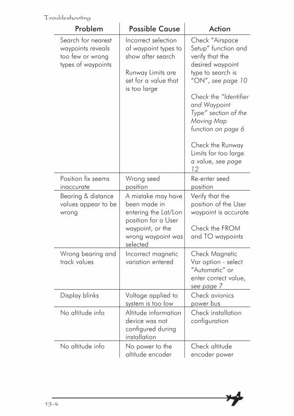
Problem Possible Cause Action
Search for nearestwaypoints revealstoo few or wrongtypes of waypoints
Incorrect selectionof waypoint types toshow after search
Runway Limits areset for a value thatis too large
Check “AirspaceSetup” function andverify that thedesired waypointtype to search is“ON”, see page 10
Check the “Identifierand WaypointType” section of theMoving Mapfunction on page 6
Check the RunwayLimits for too largea value, see page12
Position fix seemsinaccurate
Wrong seedposition
Re-enter seedposition
Bearing & distancevalues appear to bewrong
A mistake may havebeen made inentering the Lat/Lonposition for a Userwaypoint, or thewrong waypoint wasselected
Verify that theposition of the Userwaypoint is accurate
Check the FROMand TO waypoints
Wrong bearing andtrack values
Incorrect magneticvariation entered
Check MagneticVar option - select“Automatic” orenter correct value,see page 7
Display blinks Voltage applied tosystem is too low
Check avionicspower bus
No altitude info Altitude informationdevice was notconfigured duringinstallation
Check installationconfiguration
No altitude info No power to thealtitude encoder
Check altitudeencoder power
13-4
Troubleshooting
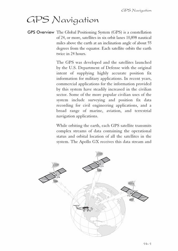
GPS NavigationGPS Overview The Global Positioning System (GPS) is a constellation
of 24, or more, satellites in six orbit lanes 10,898 nautical
miles above the earth at an inclination angle of about 55
degrees from the equator. Each satellite orbits the earth
twice in 24 hours.
The GPS was developed and the satellites launched
by the U.S. Department of Defense with the original
intent of supplying highly accurate position fix
information for military applications. In recent years,
commercial applications for the information provided
by this system have steadily increased in the civilian
sector. Some of the more popular civilian uses of the
system include surveying and position fix data
recording for civil engineering applications, and a
broad range of marine, aviation, and terrestrial
navigation applications.
While orbiting the earth, each GPS satellite transmits
complex streams of data containing the operational
status and orbital location of all the satellites in the
system. The Apollo GX receives this data stream and
GPS Navigation
14-1
processes the information to determine which
satellites are “visible” to the receiver’s antenna. With
this determination made, the receiver chooses
satellites to calculate a position fix. Using information
transmitted from three or more satellites, the unit can
calculate latitude and longitude (usually abbreviated
Lat/Lon); with four or more satellites, GPS altitude
can also be calculated.
GPS SystemAccuracy
The GPS allows a high degree of position fix
accuracy. The system can produce a position fix
accurate to within less than one meter under ideal
conditions. Due to concern for national security, the
U.S. Department of Defense introduces constantly
changing errors to the transmitted satellite data to
degrade the accuracy of the system. Called Selective
Availability, this practice limits GPS position fix
accuracy to about 100 meters, although the relative
position of the satellites to one another, their elevation
above the horizon, and other factors can also affect
accuracy of the position fix. Under optimal
conditions, accuracy can improve to within 10 meters.
GPS position fix accuracy is not affected by
atmospheric conditions.
GPS altitude is based on a mathematical model of the
shape of the earth, the WGS-84 ellipsoid. Including
intentional degradation, GPS altitude may differ from
barometric altitude by several hundred feet.
14-2
GPS Navigation
GlossaryA Altitude (GPS ALT): Altitude, as calculated by the
Apollo GX, based upon a mathematical model of theearth’s surface curvature. A substantial differencebetween this altitude value and altitude referencedto sea level may exist.
Altitude Assist: An aid that provides guidance in
descending from one altitude to another. See the
Altitude Assist description on page 14 for details.
Almanac: Data transmitted by a GPS satellite
including orbit information on all satellites, clock
correction, and atmospheric delays.
ARC: A DME arc terminator with the preceding
flight plan leg is described as an arc to this waypoint.
An ARC waypoint may follow another ARC
waypoint.
ATC Ring: On the map display, an artificial ring five
nm in diameter is drawn around airports that have a
control tower.
Automatic Terminal Information Service (ATIS):
Recorded information about weather and other
conditions at an airport, periodically updated when
conditions change.
Autonav: The function that allows you to set the GX
to scroll automatically through selected navigation
displays .
Azimuth: an arc, as measured clockwise from true or
magnetic north.
B Baro Altitude: Barometric altitude (pressure altitude
corrected for local altimeter setting). This altitude
should match the altitude displayed on your aircraft
altimeter.
Glossary
15-1
Bearing (BRG): The direction to any point, usually
measured in degrees relative to true or magnetic
north. The direction from your present position to
your destination waypoint.
C CF: Final approach course Fix. This waypoint type is
used when necessary to define a course to the FAF -
all VOR DME approaches require a course fix
waypoint. A code appended to a waypoint in the
database that may not appear on a published map.
Circular Error Probable (CEP): As applied to GPS
position fix accuracy, the radius of a circle inside of
which there exists a 50 percent chance of being
located.
Constellation: A group of stars or objects, such as
GPS satellites, in the heavens.
Coordinates: Values for latitude and longitude that
describe a geographical point on the surface of the
earth.
Course: The planned direction of travel in a
horizontal plane.
Course Deviation: A measurement of distance left or
right from the desired course of travel.
Course Deviation Indicator (CDI): A graphic
indicator of course deviation typically shown as a
graduated horizontal bar with an icon indicating the
deviation distance left or right of course.
Course Intercept: Similar to an arrival alert, arrival is
related to a course or radial to a point. When flying an
arc during an approach, the arrival alert is issued
when the aircraft is 1 nm/100 kts of intercepting the
inbound course. When Vector to Final is selected, or
you are executing a procedure turn at the FAF, the
course intercept alert occurs when the aircraft has a
Track Angle Error �45° and the cross track deviation
is � 1 nm.
15-2
Glossary
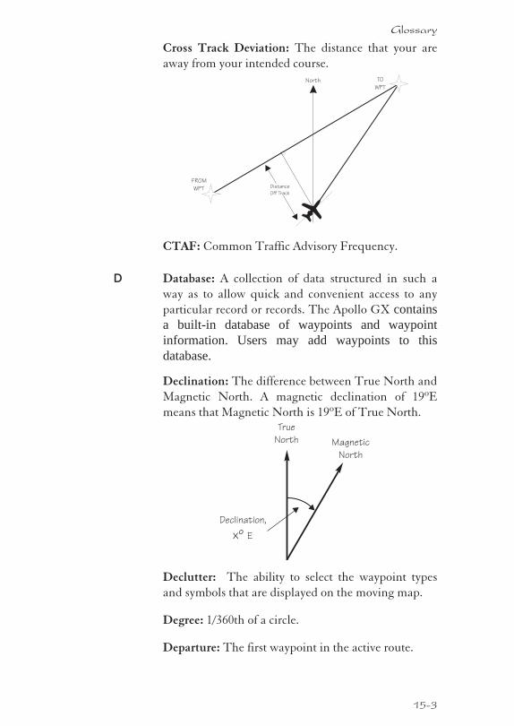
Cross Track Deviation: The distance that your are
away from your intended course.
CTAF: Common Traffic Advisory Frequency.
D Database: A collection of data structured in such a
way as to allow quick and convenient access to any
particular record or records. The Apollo GX containsa built-in database of waypoints and waypointinformation. Users may add waypoints to thisdatabase.
Declination: The difference between True North and
Magnetic North. A magnetic declination of 19ºE
means that Magnetic North is 19ºE of True North.
Declutter: The ability to select the waypoint types
and symbols that are displayed on the moving map.
Degree: 1/360th of a circle.
Departure: The first waypoint in the active route.
15-3
Glossary
True
North Magnetic
North
Declination,
Exº
TO
WPT
FROM
WPT
North
Distance
Off Track
Desired Track (DTK): The desired course of
navigation between a point of origin (FROM) and a
destination (TO) waypoint.
Destination: The last waypoint in the active route.
Dilution of Precision (DOP): A merit value for the
calculated position based on the geometrical
configuration of the satellites used; 3 is considered good,
greater than 7 is considered poor. Also called Precision
Dilution of Precision or PDOP.
Direct-To: The function or procedure that directs you
from your present position to the designated TO
waypoint.
Distance: A measure of interval in space. Also
referred to as range.
DME: Distance Measuring Equipment
Drift: Displacement from the intended course of
travel.
E Elevation: The angle of a GPS satellite above the
horizon.
Emergency Search: The function that allows you to
immediately navigate to the nearest airport in the case
of an emergency.
Ephemeris: A list of accurate positions or locations of
a celestial object as function of time.
Estimated Time of Arrival (ETA) - The estimated
time of arrival at the TO waypoint in UTC time using
a 24 hour clock.
Estimated Time En route (ETE) - The estimated
time from your present position to the TO waypoint.
F FAF: Final Approach Fix.
15-4
Glossary
FDE: The Fault Detection and Exclusion column
refers to the ability to identify and exclude a faulty
satellite and still have suitable satellite geometry at
that position.
FF: Final Approach Fix. A code appended to a
waypoint in the database that may not appear on a
published map.
Fix: A geographical location determined by either
visual reference or by electronic navigation aids.
Flight Time: Flight Time shows the elapsed time in
hours and minutes (00:00 to 99:59) from departure. If
the Flight Timer is not started the value will be
replaced with dashes. The Flight Timer options are
set in the System Functions (see page 8).
Flight Plan: A series of two or more waypoints.
G GDOP: Geometric Dilution of Precision. The
relationship between errors in receiver position and
time and in satellite range.
Global Positioning System (GPS): Also known as
NAVSTAR. A constellation of satellites launched by the
U.S. Department of Defense into six orbit lanes (four
satellites per plane) at an altitude of 10,898 nm above the
earth.
Greenwich Mean Time (GMT): See Universal Time
Coordinate (UTC).
Ground (GRND): Ground communication
frequency
Ground Speed (GS): Speed of travel across the
ground. In aviation, the relation between ground
speed and air speed is affected by the prevailing
winds.
H HDOP: Horizontal Dilution of Precision. See
Dilution Of Precision.
15-5
Glossary
Hold: Waypoint sequencing is disabled or
suspended. A hold may be automatically or manually
activated. This should not be confused with a
“holding pattern.” Pressing the OBS/HLD key
suspends waypoint sequencing.
I IAF: Initial Approach Fix.
Identifier: A name, typically abbreviated, assigned to
a waypoint. The identifier may consist of numbers
and alpha characters, up to six in length. For example,
the airport identifier for Los Angeles International
Airport is LAX.
IFAF: Initial and Final Approach fix. A combined
Initial and Final approach Fix with no intermediate
waypoints.
IFR: Instrument Flight Rules
Intersection (INT): A point defined by any
combination of courses, radials, or bearings of two or
more navigational aids.
K Knot (kt): A unit of speed equal to one nautical mile
per hour.
L Latitude (Lat): Any line circling the earth parallel to
the equator, measured in degrees, minutes, and
seconds north and south of the equator.
LFAC: Landing FACility.
Longitude (Lon): Any line from the north to the
south pole, measured in degrees, minutes, and
seconds of a circle, east or west of the Prime Meridian
(Greenwich, England).
M MA: Missed Approach Point. A code appended to a
waypoint in the database that may not appear on a
published map.
15-6
Glossary
Magnetic North: The region, some distance from the
geographic north pole where the earth’s magnetic
lines concentrate. A magnetic compass points to the
magnetic north.
Magnetic Variation (Mag Var): The angle between
the magnetic and true north. At various points on the
earth it is different due to local magnetic disturbances.
It is shown on charts as isogonic lines marked with
degrees of variation, either east or west. These degrees
must be added to or subtracted from the true course to
get the magnetic course. (Easterly variations are
deducted, and westerly variations are added.) The
Apollo GX automatically sets magnetic variation to0 degrees at positions above 70 degrees north orsouth latitude. See Declination.
MAHP: Missed Approach Hold Point.
MAP: Missed Approach Point.
Map Datum: A mathematical model of the earth used
for the purpose of creating navigation charts and
maps. The Apollo GX uses the WGS-84 map datum.
MESA: Minimum En route Safe Altitude is the
highest MSA for every point between the aircraft
present position and the “TO” waypoint with a 5 nm
buffer around the course.
Meter (m): A metric distance measurement equal to
39.37 inches.
Minute: 1/60th of a degree.
MSA: Minimum Safe Altitude. The elevation of the
highest obstruction near the aircraft plus a 1,000 or
2,000 foot buffer added for safety. In
non-mountainous terrain, a 1,000 foot buffer is added.
In mountainous terrain, a 2,000 foot buffer is added.
The result is rounded to the nearest 100 feet.
15-7
Glossary
N Nautical Mile (nm): A distance measurement equal
to 6,076 feet, or 1.15 statute mile. One nautical mile is
also equal to one minute of latitude.
NAVSTAR: The name given to GPS satellites formed
from the acronym for NAVigation System with Time
And Ranging.
Non-Directional Beacon (NDB): A low
frequency/medium frequency navigation aid sending
non-directional signals that can be used for
navigation.
O OBS: Omni-Bearing Selector.
P Parallel Track Offset: A course that is parallel to the
designated course, but offset to the right or left by a
given distance.
PDOP: Position Dilution of Precision. See Dilution of
Precision.
PRN: GPS satellite Pseudo-Random Numbers are
used to uniquely identify satellites. This is different
than the SVN (Space Vehicle Number, or satellite
serial number). When excluding satellites from the
RAIM Prediction , use the PRN number found on the
NOTAMs and NANUs, not the SVN.
R Radial: Any of the 360 magnetic courses from a VOR or
similar navigational aid, beginning at the navigational
aid and proceeding outward in a straight line.
RAIM: Receiver Autonomous Integrity Monitoring. A
method of predicting possible system accuracy errors
that may be caused by bad satellite data. The RAIM
algorithm requires that more satellites are available and
usable than required for a normal GPS position fix.
Range: The distance from the present position to a
destination waypoint.
15-8
Glossary
Relative Bearing Indicator: The Relative Bearing
Indicator is an arrow next to the Bearing value that
indicates an approximate bearing to a waypoint or
airspace relative to the aircraft’s current track when
your current ground speed is more than 5 knots.
RW: Runway Fix. A code appended to a waypoint in
the database that may not appear on a published map.
S Second: 1/60th of a minute of a degree.
Seed Position: A latitude and longitude position fix
approximately equal to the current position that the
Apollo GX uses to determine the location ofavailable satellites from which signals may bereceived.
Selective Availability (SA): The degradation of
accuracy of GPS position fix data by the United States
Department of Defense for civilian use.
Space Vehicle (SV): A GPS satellite.
Statute Mile: A distance measurement equal to 5,280
feet or 0.87 of a nautical mile.
T Three-dimensional (3D) Position Fix: A position fix
defined by latitude, longitude, and altitude.
15-9
Glossary
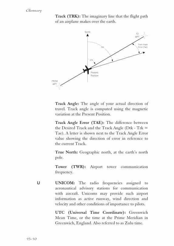
Track (TRK): The imaginary line that the flight path
of an airplane makes over the earth.
Track Angle: The angle of your actual direction of
travel. Track angle is computed using the magnetic
variation at the Present Position.
Track Angle Error (TAE): The difference between
the Desired Track and the Track Angle (Dtk - Trk =
Tae). A letter is shown next to the Track Angle Error
value showing the direction of error in reference to
the current Track.
True North: Geographic north, at the earth’s north
pole.
Tower (TWR): Airport tower communication
frequency.
U UNICOM: The radio frequencies assigned to
aeronautical advisory stations for communication
with aircraft. Unicoms may provide such airport
information as active runway, wind direction and
velocity and other conditions of importance to pilots.
UTC (Universal Time Coordinate): Greenwich
Mean Time, or the time at the Prime Meridian in
Greenwich, England. Also referred to as Zulu time.
15-10
Glossary
TO
WPT
FROM
WPT
North
Track Angle
Error (Tae)
Present
Position
TRK
DTK
UTC Differential: The difference in time between
that at the present position and UTC.
UTM (Universal Transverse Mercator map
projection system): Also known as Military Grid
Coordinates, the UTM grid consists of 60
north-south/east-west zones, each six degrees wide in
longitude.
V VFR: Visual Flight Rules.
VOR: Very High Frequency Omni-directional range.
A navigational aid that transmits signals such that a
receiver can indicate its current radial or bearing from
the transmitter.
VHF: Very High Frequency. The range of
frequencies between 30 and 300 MHz.
VNAV: Vertical Navigation. See Altitude Assist.
W Waypoint: A navigation fix used in area navigation
and defined by latitude and longitude coordinates.
15-11
Glossary

Notes
15-12
Glossary
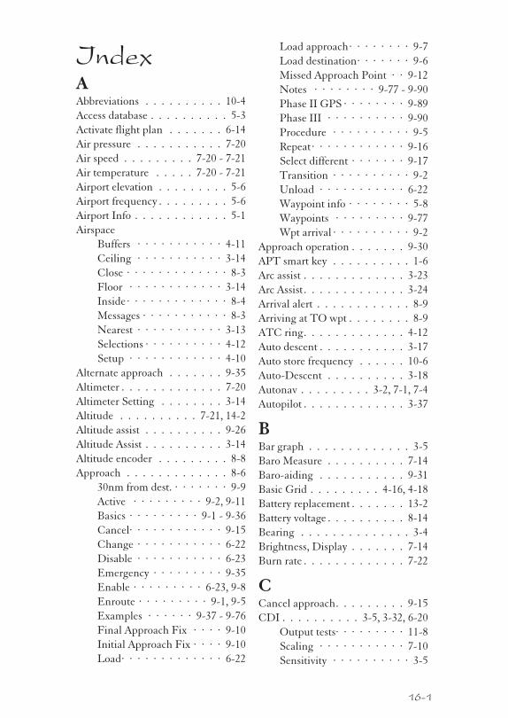
IndexAAbbreviations . . . . . . . . . . 10-4
Access database . . . . . . . . . . 5-3
Activate flight plan . . . . . . . 6-14
Air pressure . . . . . . . . . . . 7-20
Air speed . . . . . . . . . 7-20 - 7-21
Air temperature . . . . . 7-20 - 7-21
Airport elevation . . . . . . . . . 5-6
Airport frequency . . . . . . . . . 5-6
Airport Info . . . . . . . . . . . . 5-1
Airspace
Buffers · · · · · · · · · · · 4-11
Ceiling · · · · · · · · · · · 3-14
Close · · · · · · · · · · · · · 8-3
Floor · · · · · · · · · · · · 3-14
Inside · · · · · · · · · · · · · 8-4
Messages · · · · · · · · · · · 8-3
Nearest · · · · · · · · · · · 3-13
Selections · · · · · · · · · · 4-12
Setup · · · · · · · · · · · · 4-10
Alternate approach . . . . . . . 9-35
Altimeter . . . . . . . . . . . . . 7-20
Altimeter Setting . . . . . . . . 3-14
Altitude . . . . . . . . . . 7-21, 14-2
Altitude assist . . . . . . . . . . 9-26
Altitude Assist . . . . . . . . . . 3-14
Altitude encoder . . . . . . . . . 8-8
Approach . . . . . . . . . . . . . 8-6
30nm from dest. · · · · · · · 9-9
Active · · · · · · · · · 9-2, 9-11
Basics · · · · · · · · · 9-1 - 9-36
Cancel· · · · · · · · · · · · 9-15
Change · · · · · · · · · · · 6-22
Disable · · · · · · · · · · · 6-23
Emergency · · · · · · · · · 9-35
Enable · · · · · · · · · 6-23, 9-8
Enroute · · · · · · · · · 9-1, 9-5
Examples · · · · · · 9-37 - 9-76
Final Approach Fix · · · · 9-10
Initial Approach Fix · · · · 9-10
Load· · · · · · · · · · · · · 6-22
Load approach· · · · · · · · 9-7
Load destination· · · · · · · 9-6
Missed Approach Point · · 9-12
Notes · · · · · · · · 9-77 - 9-90
Phase II GPS · · · · · · · · 9-89
Phase III · · · · · · · · · · 9-90
Procedure · · · · · · · · · · 9-5
Repeat · · · · · · · · · · · · 9-16
Select different · · · · · · · 9-17
Transition · · · · · · · · · · 9-2
Unload · · · · · · · · · · · 6-22
Waypoint info · · · · · · · · 5-8
Waypoints · · · · · · · · · 9-77
Wpt arrival · · · · · · · · · · 9-2
Approach operation . . . . . . . 9-30
APT smart key . . . . . . . . . . 1-6
Arc assist . . . . . . . . . . . . . 3-23
Arc Assist . . . . . . . . . . . . . 3-24
Arrival alert . . . . . . . . . . . . 8-9
Arriving at TO wpt . . . . . . . . 8-9
ATC ring. . . . . . . . . . . . . 4-12
Auto descent . . . . . . . . . . . 3-17
Auto store frequency . . . . . . 10-6
Auto-Descent . . . . . . . . . . 3-18
Autonav . . . . . . . . . 3-2, 7-1, 7-4
Autopilot . . . . . . . . . . . . . 3-37
BBar graph . . . . . . . . . . . . . 3-5
Baro Measure . . . . . . . . . . 7-14
Baro-aiding . . . . . . . . . . . 9-31
Basic Grid . . . . . . . . . 4-16, 4-18
Battery replacement . . . . . . . 13-2
Battery voltage . . . . . . . . . . 8-14
Bearing . . . . . . . . . . . . . . 3-4
Brightness, Display . . . . . . . 7-14
Burn rate . . . . . . . . . . . . . 7-22
CCancel approach. . . . . . . . . 9-15
CDI . . . . . . . . . . 3-5, 3-32, 6-20
Output tests· · · · · · · · · 11-8
Scaling · · · · · · · · · · · 7-10
Sensitivity · · · · · · · · · · 3-5
16-1
CDI reverse sensing . . . . . . . 9-22
Change approach . . . . . . . . 6-22
Cleaning . . . . . . . . . . . . . 13-2
Clear exclusion list . . . . . . . 9-35
Clear flight plan wpts . . . . . . 6-17
Close . . . . . . . . . . . . 4-11, 8-3
Close altitude . . . . . . . . . . . 8-4
Com
Headphone level · · · · · 10-12
Info · · · · · · · · · · · · · 10-9
Intercom squelch · · · · · 10-10
Key · · · · · · · · · · · · · · 1-8
Noise level· · · · · · · · · 10-10
Sidetone level · · · · · · · 10-12
Signal strength · · · · · · 10-10
Comm radio
Test · · · · · · · · · · · · · 11-1
Comm Radio . . . . . . 10-1 - 10-12
Auto stack list· · · · · · · · 10-6
Emergency channel · · · · 10-8
Frequency abbreviations· · 10-4
Intercom · · · · · · · · · · 10-8
Monitoring frequencies · · 10-3
Recalling frequencies · · · 10-4
Selecting frequencies · · · 10-2
Squelch · · · · · · · · · · · 10-8
Stuc mic· · · · · · · · · · · 10-9
User frequencies · · · · · · 10-7
Weather channel · · · · · · 10-7
Comments
See alsoFlight plan comments
See alsoWaypoint comments
Continue flight plan . . . . . . 6-21
Controls . . . . . . . . . . . . . . 1-3
Conventions . . . . . . . . . . . 1-iv
Copy flight plan . . . . . . . . . 6-16
Countdown timer . . . . . 3-22, 8-14
Courrse intercept . . . . . . . . 8-10
Create User waypoint . . . . . . 4-29
Creeping Line Pattern . . . . . 4-23
Cross track distance. . . . . . . . 3-6
Crossing FAF . . . . . . . . . . 9-12
Current time . . . . . . . . . . . 2-1
Customizing Nav pages . . . . . 7-2
DDatabase . . . . . . . . . . 5-1 - 5-16
Database expired . . . . . . . . 8-13
Database invalid . . . . . . . . . 8-13
Database message . . . . . . . . 11-5
Database test . . . . . . . . . . . 11-4
Datacard . . . . . . . . . . . . . 5-16
Date and Time . . . . . . . . . 7-11
Delete flight plan . . . . . . . . 6-18
Density altitude . . . . . . . . . 7-21
Descent rate . . . . . . . . . . . 3-17
Description
Cross track distance · · · · · 3-6
Moving map · · · · · · · · · 4-1
Nav display · · · · · · · · · 3-4
Nav terms · · · · · · · · · · 3-1
To-From switching · · · · · 3-6
Waypoint · · · · · · · · · · 11-7
Desired heading . . . . . . . . . 7-21
Desired track . . . . . . . . . . . 3-6
Diamond . . . . . . . . . . . . . 3-1
Direct-To . 2-7, 3-31 - 3-32, 6-9, 7-8,9-18
May Clear · · · · · · · · 2-7, 7-9
Never Clears · · · · · · · · · 7-9
OBS · · · · · · · · · · · · · 3-35
Disable approach . . . . . . . . 6-23
Display . . . . . . . . . . . . . . 1-2
Flashing · · · · · · · · · · · 1-iv
Test · · · · · · · · · 7-14, 11-11
Display brightness. . . . . . . . 7-14
Distance off track . . . . . . . . . 3-5
Distance to waypoint . . . . . . 3-25
DME Arc . . 3-24, 8-11 - 8-12, 9-26,9-63, 9-87, 12-1
DTK Up. . . . . . . . . . . . . . 4-5
Duplicate names . . . . . . . 2-4, 5-4
EEdit owner information. . . . . 7-16
EEPROM . . . . . . . . . . . . 11-4
Elevation . . . . . . . . . . . . . 5-6
E-Mail. . . . . . . . . . . . . . . 1-ii
Emergency approach . . . . . . 9-35
16-2
Index
Emergency channel . . . . . . . 10-8
Emergency search . . . . . . . . 3-9
Empty TO waypoint . . . . . . . 8-4
En route operation . . . . . . . 9-30
Enable approach . . . . . . 6-23, 9-8
Encoder altitude . . . . . . . . . 3-15
Encoding altimeter . . . . . . . 7-20
Ending Altitude . . . . . . . . . 3-18
Enroute. . . . . . . . . . . . 9-1, 9-5
Error messages . . . . . . . . . . 8-3
Estimate ground speed . . . . . 6-16
Estimated fuel flow . . . . . . . 6-17
Estimated time enroute 3-4, 6-7 - 6-8
Estimated time of arrival . . 3-9, 6-7
ETA to waypoint . . . . . . . . 3-25
ETE to waypoint . . . . . . . . 3-25
Examples
Approach · · · · · · 9-37 - 9-76
Direct-To · · · · · · · · · · 3-32
DME arc · · · · · · · · · · 9-63
Procedure turns · · · 9-66, 9-68
Exclude satellite . . . . . . . . . 9-34
Expanding Square Pattern . . . 4-26
External Annunciators . . 1-3, 11-10
FFactory . . . . . . . . . . . . . . 13-1
FAF . . . . . . . . . . . . 9-10, 9-12
FCC Notice . . . . . . . . . . . 1-iii
Features . . . . . . . . . . . . . . 1-9
Find waypoint . . . . . . . . 2-1, 2-6
Flight plan . . . . . . . . . 6-1 - 6-26
Activate · · · · · · · · · · · 6-14
Activating · · · · · · · · · · 2-9
Active · · · · · · · · · · · · · 6-2
Clear waypoints · · · · · · 6-17
Comments · · · · · · · · · 6-23
Continue · · · · · · · · · · 6-21
Copy plan· · · · · · · · · · 6-16
Creating · · · · · · · · · 2-8, 6-2
Delete plan · · · · · · · · · 6-18
Deleting legs · · · · · · · · 6-12
Editing· · · · · · · · 6-10 - 6-11
Estimate ground speed · · 6-16
Estimated fuel flow · · · · 6-17
Hold · · · · · · · · · · · · 6-18
Inserting legs · · · · · · · · 6-11
Leg info · · · · · · · · · · · 6-6
Manual leg · · · · · · · · · · 6-9
Manual leg select· · · · · · 9-19
Memory failure · · · 8-12, 11-3
New waypoint · · · · · · · 3-33
Options · · · · · · · · · · · 6-14
Pages · · · · · · · · · · · · · 6-1
Reactivate · · · · · · · · · · 6-15
Rename · · · · · · · · · · · 6-15
Rev activate · · · · · · · · · 6-15
Reverse flight plan · · · · · 6-17
Saving Active plan · · · · · 6-24
Sequencing · · · · · · · · · 6-5
Waypoint sequencing · · · 9-20
Flight simulator . . . . . 12-1 - 12-4
Operation · · · · · · · · · · 12-4
Starting · · · · · · · · · · · 12-2
Flight time . . . . . . . . . . 3-9, 7-8
Flip/Flop key . . . . . . . . . . . 1-8
Frequency abbreviations . . . . 10-4
From . . . . . . . . . . . . . . . 6-19
FROM waypoint . . . . . . . . . 3-6
From/To/Next . . . . . . 3-26, 3-29
From-To distance . . . . . . . . 3-6
Fuel . . . . . . . . . . . . . 5-7 - 6-8
Fuel endurance . . . . . . . . . 7-22
Fuel flow . . . . . . . . . . . . . 7-20
Fuel info . . . . . . . . . . . . . 7-22
Fuel Measure . . . . . . . 7-13, 7-24
Fuel range . . . . . . . . . . . . 7-22
Fuel sensor. . . . . . . . . . . . 7-20
Fuel used. . . . . . . . . . . . . 7-22
Fuel warning . . . . . . . . . . 7-23
Fuel/Air Data sensor . . . . . . 7-20
GGlide path . . . . . . . . . . . . 3-17
Glide slope . . . . . . . . . . . . 3-17
Glossary . . . . . . . . . 15-1 - 15-12
GPS . . . . . . . . . . . . 7-19, 14-1
Accuracy · · · · · · · · · · 14-2
16-3
Index
Antenna · · · · · · · · · · 11-12
Azimuth · · · · · · · · · · 7-18
Communication failure · · · 8-5
Elevation · · · · · · · · · · 7-18
Error · · · · · · · · · · · · · 8-5
Failure · · · · · · · · · · · · 8-4
Health · · · · · · · · 7-17, 11-11
Introduction· · · · · 14-1 - 14-2
Position · · · · · · · · · · · 3-21
Reset· · · · · · · · · · · · · 7-19
Satellite failure · · · · · · · 9-32
Satellites· · · · · · · 7-18, 11-12
Sensor · · · · · · · · · · · · 7-17
Signal strength · · · · · · 11-11
Signal Strength· · · · · · · 7-18
Time · · · · · · · · · · · · 7-17
GPSS . . . . . . . . . . . . . . . 3-37
Grid Line Display . . . . . . . . 4-15
Ground speed . . . . . . . . . . . 3-7
GX50 description . . . . . . . . . 1-2
GX55 description . . . . . . . . . 1-2
GX60 description . . . . . . . . . 1-2
HHeadphone level . . . . . . . . 10-12
Heat . . . . . . . . . . . . . . . 13-2
Help! . . . . . . . . . . . . . . . 13-1
History of Revisions . . . . . . . 1-ii
Hold . . . . . . . . . 3-19, 3-30, 6-18
Hold altitude . . . . . . . . 3-16, 8-8
Hold buffer . . . . . . . . . . . 3-16
Holding at To wpt . . . . . . . 8-11
Holding patterns. . 6-19, 9-24 - 9-25
HSI . . . . . . . . . . . . . . . . 3-17
IIAF . . . . . . . . . . . . . . . . 9-10
IFR output tests . . . . . . . . . 11-8
II Morrow . . . . . . . . . . . . 13-1
ILS runway . . . . . . . . . . . . 5-6
Indicated air speed . . . . . . . 7-21
Info . . . . . 3-14, 5-1, 5-5, 6-23, 8-3
Info 28, 37, 40, 60, 62, 98 . . . . 10-6
INSIDE . . . . . . . . . . . . . . 8-4
INT smart key . . . . . . . . . . 1-6
Intercom . . . . . . . . . . . . . 10-8
Intercom level . . . . . . . . . 10-11
Intercom squelch. . . . . . . . 10-10
Intersection info . . . . . . . . . 5-2
KKey. . . . . . . . . . . . . . . . . 1-4
APT · · · · · · · · · · · · · 1-6
Database · · · · · · · · · · · 1-5
Direct-To · · · · · · · · · · 1-5
Flight Plan · · · · · · · · · · 1-5
Hard · · · · · · · · · · · · · 1-iv
Info · · · · · · · · · · · · · · 1-4
INT· · · · · · · · · · · · · · 1-6
List · · · · · · · · · · · · · · 1-6
Map· · · · · · · · · · · · · · 1-5
Map orient · · · · · · · · · · 1-7
Map reference · · · · · · · · 1-7
Map setup · · · · · · · · · · 1-7
Message · · · · · · · · · · · 1-5
Nav · · · · · · · · · · · · · · 1-4
NDB · · · · · · · · · · · · · 1-6
Nearest · · · · · · · · · · · · 1-4
NRST · · · · · · · · · · · · 3-10
Route line · · · · · · · · · · 1-7
RTE · · · · · · · · · · · · · 4-4
Scan · · · · · · · · · · · 1-7, 4-3
Select · · · · · · · · · · · · · 1-4
Skip · · · · · · · · · · 1-6, 11-1
Smart · · · · · · · · · · · · 1-iv
System · · · · · · · · · · · · 1-6
User · · · · · · · · · · · · · 1-6
VOR · · · · · · · · · · · · · 1-6
XIT· · · · · · · · · · · · · · 1-8
Keys
Hard · · · · · · · · · · · · · 1-4
Smart · · · · · · · · · · · · · 1-5
Knobs . . . . . . . . . . . . . . . 1-iv
LLarge knob . . . . . . . . . . . . 1-3
Lat/Lon position . . . . . . . . . 5-8
Lat/Lon reference . . . . . . . . 11-7
16-4
Index
Lat/Lon units . . . . . . . . . . . 7-4
Left engine fuel . . . . . . . . . 7-23
Leg distance . . . . . . . . . . . . 3-6
List key . . . . . . . . . . . . . . 1-6
Load approach . . . . . . . 6-22, 9-7
Load destination . . . . . . . . . 9-6
Local altimeter. . . . . . . . . . 3-15
Localizer . . . . . . . . . 3-39 - 3-40
Low fuel . . . . . . . . . . . . . . 8-8
MMagnetic heading . . . . 7-20 - 7-21
Magnetic variation . . . . . 7-7, 8-13
Magnetic wind direction . . . . 7-22
Manual leg activation . . . . . . 6-9
Manual prediction. . . . . . . . 9-33
Manuals . . . . . . . . . . . . . . 1-ii
Map . . . . . . . . . . . . . . . . 5-7
Map reference . . . . . . . . . . . 4-6
Map setup . . . . . . . . . . 1-7, 4-4
Map Setup
Search and Rescue · · · · · 4-16
Map waypoint keys . . . . . . . . 1-6
Mark position . . . . . . . . . . 4-28
May clear . . . . . . . . . . . . . 7-9
May Clear . . . . . . . . . . . . . 2-7
Measurement units . . . . . . . . 7-6
Memory failure . . . . . . 8-13, 11-1
Memory loss or failure . . . . . 8-12
Memory test . . . . . . . . 11-2, 11-4
Message . . . . . . . . . . 8-1 - 8-14
Microphone . . . . . . . . . . . 10-9
Minimum enroute safe altitude . 3-8
Minimum safe altitude . . . . . . 3-8
Misc sensors . . . . . . . . . . . 7-20
Missed approach. . . . . . . . . 9-13
Missed approach point . . . . . 9-12
Monitor frequency . . . . . . . 10-3
Moving map . . . . . . . . . . . 2-10
Setup · · · · · · · · · · · · 2-10
Moving Map. . . . . 2-10, 4-1 - 4-32
Controls · · · · · · · · · · · 4-2
Full screen · · · · · · · · · · 4-1
Idents · · · · · · · · · · · · · 4-6
Map & Nav info · · · · · · · 4-3
Orientation · · · · · · · · · 4-5
Route line · · · · · · · · · · 4-4
Scale · · · · · · · · · · · · · 4-3
Setup · · · · · · · · · · · · · 4-4
Multiple facilities . . . . . . . . . 5-4
See alsoDuplicate names
NNav page choices . . . . . . . . . 7-5
Nav superflag tests . . . . . . . 11-9
Nav Valid flag tests . . . . . . . 11-9
Navigation . . . . . . . . . . 3-1, 7-1
Displays · · · · · · · · · · · 3-1
Empty To waypoint · · · · · 8-4
Home page· · · · · · · · · · 3-1
Pages · · · · · · · · · · 3-3 - 7-4
Programmable pages · · · · 7-2
Terms · · · · · · · · · · · · 3-1
NDB Info . . . . . . . . . . . . . 5-2
NDB smart key . . . . . . . . . . 1-6
Nearest waypoint . . 2-6, 3-12 - 4-13,5-9, 9-36, 10-6
Nearest waypoint search . . 3-9, 5-1
Never clear . . . . . . . . . . . . 7-9
Noise level . . . . . . . . . . . 10-10
Non-volatile RAM test . . . . . 11-3
North Up . . . . . . . . . . . . . 4-5
NRST 1-2, 1-4, 2-6, 3-9 - 3-10, 3-12,4-6, 4-13, 9-36, 13-3
NVRAM . . . . . . . . . . . . . 11-4
OOBS . . . . . . . . . 3-35, 8-12, 9-18
Offset distance . . . . . . . . . . 3-17
Ordering Information . . . . . . 1-ii
ORI key . . . . . . . . . . . . . . 1-7
Outside air temperature. . . . . 7-21
Owner information . . . . . . . 7-15
Owner message . . . . . . . . . 11-2
PParallel Line Pattern . . . . . . 4-21
Parallel track . . . . . . . 3-19, 3-21
Approach conflict · · · · · · 8-6
16-5
Index
In Use · · · · · · · · · · · · 3-19
Standby · · · · · · · · · · · 3-19
Part numbers . . . . . . . . . . . 1-ii
Password . . . . . . . . . . . . . 7-16
Pattern . . . . . . . . . . . . . . 4-20
PDOP . . . . . . . . . . . . . . 3-21
Phase II Approach. . . . . . . . 9-89
Phase III Approach . . . . . . . 9-90
Photocell . . . . . . . . . . . . . 1-2
Power knob . . . . . . . . . . . . 1-3
Power Up . . . . . . . . . . . . . 2-1
Pressure altitude . . . . . . . . . 7-21
Procedure turn . . . . . . . . . . 4-4
Procedure Turns . 9-21 - 9-22, 9-66,9-68
Programmable Nav pages . . . . 7-2
RRAIM . . . . . . . . . 8-5, 9-29, 9-33
Clear exclusion list · · · · · 9-35
Exclude satellite · · · · · · 9-34
Manual prediction · · · · · 9-33
RAIM alarm . . . . . . . . . . . 9-32
Range . . . . . . . . . . . . . . . 3-4
Rate of climb. . . . . . . . . . . 7-21
Reactivate . . . . . . . . . . . . 6-15
Recall frequency . . . . . . . . . 10-4
REF key . . . . . . . . . . . . . . 1-7
Reference position . . . . . . . . 11-7
Reference Waypoint 3-10, 5-10, 11-6
Relative Bearing Indicator . . . . 3-3
Remove unit from aircraft . . . 12-2
Rename flight plan . . . . . . . 6-15
Repeat approach . . . . . . . . . 9-16
Replace unit in aircraft . . . . . 12-2
Reserve fuel . . . . . . . . . . . 7-23
Rev Activate . . . . . . . . . . . 6-15
Reverse flight plan. . . . . . . . 6-17
RF signal strength . . . . . . . 10-10
Right engine fuel . . . . . . . . 7-23
RNAV . . . . . . . . . . . . 5-16, 9-1
Route line . . . . . . . . . . . . . 4-4
Route line key . . . . . . . . . . . 4-4
RTE key . . . . . . . . . . . 1-7, 4-4
Runway info. . . . . . . . . . . . 5-7
Runway length . . . . . . 3-12, 5-11
Runway limits . . . . . . . . . . 3-12
Runway surface . . . . . . . . . 3-13
SSave active flight plan . . . . . . 6-24
Scan . . . . . . . . . . . . . . . . 4-3
Scan key . . . . . . . . . . . . . . 1-7
Search and Rescue. . . . . . . . 4-14
Basic Grid · · · · · · 4-16, 4-18
Create user waypoint · · · 4-29
Creeping Line Pattern · · · 4-23
Expanding Square · · · · · 4-26
Grid Line Display · · · · · 4-15
Map Setup · · · · · · · · · 4-16
Mark position · · · · · · · 4-28
Parallel Line Pattern · · · · 4-21
Sectional Chart Grid· · · · 4-19
Select pattern · · · · · · · · 4-20
Setting up a search pattern 4-32
US Grid Type · · · · · · · 4-15
Search around ref wpt. . . . . . 3-10
Sectional Chart Grid . . . . . . 4-19
Seed Position . . . . . . . . . . 11-5
Select a waypoint . . . . . . 2-1, 2-3
Select different approach . . . . 9-17
Setting measurement units. . . . 7-6
Setting up a search pattern . . . 4-32
Sidetone level. . . . . . . . . . 10-12
Skip . . . . . . . . . . . . . 1-6, 11-1
Small knob . . . . . . . . . . . . 1-3
Software memory test . . . . . . 11-2
Software version . . . . . . . . . 7-12
SOON . . . . . . . . . . . . . . . 8-3
Sort waypoints . . . . . . . . . . 2-2
Special use airspace . . . . . . . 3-13
Specifications . . . . . . . 1-9 - 1-12
Speed . . . . . . . . . . . . . . . 7-22
Squelch knob . . . . . . . . . . . 1-3
Standby . . . . . . . . . . . . . 3-20
Start up displays . . . . 11-1 - 11-12
Startup bypass . . . . . . . . . . 11-1
Storing a waypoint . . . . . . . . 2-5
Stuck microphone . . . . . . . . 10-9
16-6
Index
Sunset/Sunrise time . . . . . . . 5-8
Symbol
Triangle · · · · · · · · · · · 3-5
System . . . . . . . . . . . 7-1 - 7-24
Navigation Info · · · · · · · 7-1
System Info · · · · · · · · · 7-11
TTechnical assistance. . . . . . . 13-1
Terminal operation . . . . . . . 9-30
Tips. . . . . . . . . . . . . . . . 6-26
To . . . . . . . . . . . . . . . . 6-19
TO waypoint . . . . 2-4, 3-6, 4-1, 8-9
TO-FROM flag tests . . . . . . 11-8
Total fuel. . . . . . . . . . . . . 7-23
Track angle . . . . . . . . . . . . 3-7
Track angle error . . . . . . . . . 3-7
Track History . . . . . . . . . . . 4-8
Strategy· · · · · · · · · · · · 4-8
Track Up . . . . . . . . . . . . . 4-5
Transition . . . . . . . . . . . . . 9-2
Transmit Mic. . . . . . . . . . 10-11
Troubleshooting . . . . . 13-1 - 13-4
True air speed . . . . . . . . . . 7-21
True air temperature . . . . . . 7-21
True north . . . . . . . . . . . . 7-7
True wind direction . . . . . . . 7-22
TSO C129 overlay. . . . . . . . 9-77
Turn anticipation . . . . . . . . 3-36
Turn rate . . . . . . . . . . . . . 7-21
UUnderline. . . . . . . . . . . . . 1-iv
Units . . . . . . . . . . . . . . . . 7-6
Unload approach . . . . . . . . 6-22
Update User Wpt . . . . . . . . 5-12
US Grid Type . . . . . . . . . . 4-15
User database memory failure . 11-3
User frequency . . . . . . . . . 10-7
User waypoint
Create · · · · · · · · · 5-9 - 5-10
Delete · · · · · · · · · · · · 5-12
Information · · · · · · · · · 5-3
Modify · · · · · · · · · · · 5-13
User waypoint info . . . . . . . . 5-3
User Wpt
Update position · · · · · · 5-12
USR smart key . . . . . . . . . . 1-6
UTC time . . . . . . . . . . 3-9, 11-5
UTM . . . . . . . . . . . . . . . 7-4
VVDI. . . . . . . . . . . . . . . . 3-17
VDI flag tests . . . . . . . . . . 11-10
VDI output tests . . . . . . . . . 11-9
Vector to Final. . . . . . . . . . 9-27
Vertical deviation . . . . . . . . 3-17
VNAV . . . . . . . . . . . . . . 3-14
Volume knob . . . . . . . . . . . 1-3
VOR Info . . . . . . . . . . 3-39, 5-2
VOR smart key . . . . . . . . . . 1-6
WWaypoint
Airport info · · · · · · · · · 5-1
Approach · · · · · · · · · · 9-77
Arrival · · · · · · · · · · 8-9, 9-2
Auto OBS crossing · · · · · 8-12
Comment · · · · · · · · · · 5-8
Comments· · · · · · 5-14 - 5-15
Create · · · · · · · · · 5-9 - 5-10
Database · · · · · · · 5-1 - 5-16
Destination · · · · · · · · · 6-23
FROM · · · · · · · · · · · 3-26
From/To/Next · · · · · · · 3-26
Information · · · · 2-4, 5-1, 5-3
Intersection info · · · · · · · 5-2
Last used · · · · · · · · · · 3-11
LOC-DME · · · · · · · · · 9-69
Map· · · · · · · · · · · · · · 5-7
Map identifier · · · · · · · · 4-2
Naming conventions· · · · 9-87
NDB info · · · · · · · · · · 5-2
Next · · · · · · · · · · · · · 3-29
Scan · · · · · · · · · · · · · 4-3
Selection · · · · · · · · · · · 2-1
Sequencing · · · 6-5, 9-20, 9-24
To· · · · · · · · · · · 3-28, 8-11
16-7
Index

Type · · · · · · · · · · · 1-6, 4-6
Update User · · · · · · · · 5-12
User info · · · · · · · · · · · 5-3
VOR info · · · · · · · · · · · 5-2
Waypoint alert . . . . . . . . . . 8-10
Weather channel . . . . . . . . 10-7
Web Page . . . . . . . . . . . . . 1-ii
Wind direction. . . . . . . . . . 7-22
Wind speed . . . . . . . . . . . 7-22
XXIT key . . . . . . . . . . . . . . 1-8
16-8
Index


© 2001 by UPS Aviation Technologies, Inc.
2345 Turner Rd., S.E.
Salem, OR 97302
U.S.A.
Phone 503.581.8101
800.525.6726
In Canada 800.654.3415
FAX 503.364.2138
http://www.upsat.com
Part #560-0961-03
July 2001