Embed Size (px)
Citation preview

TECHNICAL DATA BOOK
CONTENTS
1. REFERENCE SERVICE MANUAL............................................. 22. SPECIFICATIONS....................................................................... 33. OUTLINES AND DIMENSIONS................................................ 254. WIRING DIAGRAM................................................................... 525. REFRIGERANT SYSTEM DIAGRAM...................................... 696. PERFORMANCE CURVES...................................................... 717. CORRECTION FACTORS........................................................ 738. APPLICABLE EXTENSION PIPE FOR EACH MODEL.......... 749. AIR FLOW DATA...................................................................... 77
10. NOISE CRITERION CURVES................................................. 10411. OPTIONAL PARTS.......................................................................... 127
<Indoor unit>[Model names]
R410A
PLA-RP·BA(2)PLA-RP·AAPLA-RP·AA2PEAD-RP·JA(L)PEAD-RP·EA(2)PEAD-RP·GAPKA-RP·GAL PKA-RP·HALPKA-RP·FAL(2) PKA-RP·KALPCA-RP·GA(2) PCA-RP·KAPCA-RP·HAPSA-RP·GAPMH-P·BA
<Outdoor unit>[Model names]
No. OCS07REVISED EDITION-D
SPLIT-TYPE, HEAT PUMP AIR CONDITIONERSSPLIT-TYPE, AIR CONDITIONERS
PUH-P71/100VHAPUH-P71/100/125/140YHAPU-P71/100VHAPU-P71/100/125/140YHA
October 2009
kW Model
Revision:• PLA-RP140BA2, PEAD-RP·JA(L),
PCA-RP·KA, PKA-RP·HAL/KAL are added, and outdoor unit data has been modified in REVISED EDITION-D.
• Some descriptions have been modified.
• Please void OCS07 REVISED EDITION-C.

2
1 REFERENCE SERVICE MANUAL
For information on service, please refer to the service manual as follows.
1-1. Indoor UnitModel name Service Ref. Service
Manual No.
PLA-RP35/50/60/71/100/125/140BAPLA-RP140BA2
PLA-RP35/50/60/71/100/125/140BA#2.UKPLA-RP140BA2.UK
OCH412OCB412
PLA-RP35/50/60/71AAPLA-RP35/50/60/71AA.UK OC335
PLA-RP35/50/60/71AA OC327
PLA-RP100/125/140AA2 PLA-RP100/125/140AA2.UK OC357
PCA-RP50/60/71/100/125/140KA PCA-RP50/60/71/100/125/140KA OCH454OCB454
PCA-RP50/60/71/100/125/140GAPCA-RP50GA2
PCA-RP50/60/71/100/125/140GAPCA-RP50GA2 OC328
PCA-RP71/125HA PCA-RP71/125HA#1 OC329
PKA-RP35/50HAL PKA-RP35/50HAL OCH453OCB453
PKA-RP60/71/100KAL PKA-RP60/71/100KAL.TH OCH452OCB452
PKA-RP35/50GAL PKA-RP35/50GAL OC330
PKA-RP60/71/100FALPKA-RP50FAL2
PKA-RP60/71/100FALPKA-RP50FAL2 OC331
PSA-RP71/100/125/140GA PSA-RP71/100/125/140GA#1 OC332
PEAD-RP35/50/60/71/100/125/140JA(L) PEAD-RP35/50/60/71/100/125/140JA(L).UKHWE08130
BWE08240
PEAD-RP50/60/71/125/140EAPEAD-RP35/100EA2
PEAD-RP50/60/71/125/140EA.UKPEAD-RP35/100EA2.UK HWE05210
PEAD-RP60/71/100GA PEAD-RP60/71/100GA.UK HWE05060
PMH-P25/35/50BA PMH-P25/35/50BA OC333
1-2. Outdoor UnitModel name Service Ref. Service
Manual No.
PUH-P71/100VHAPUH-P71/100/125/140YHAPU-P71/100VHAPU-P71/100/125/140YHA
PUH-P71/100VHA(1).UKPUH-P71/100VHA#2.UKPUH-P71/100VHAR3.UKPUH-P71/100/125/140YHA(1).UKPUH-P71/100/125/140YHA#2.UKPUH-P71/100/125/140YHAR3.UKPU-P71/100VHA(1).UKPU-P71/100VHA#2.UKPU-P71/100VHAR3.UKPU-P71/100/125/140YHA(1).UKPU-P71/100/125/140YHA#2.UKPU-P71/100/125/140YHAR3.UK
OC379

3
SPECIFICATIONS2
NOTE: 1. Rating conditions (ISO T1)Cooling Indoor : D.B. 27 (80°F) W.B. 19 (66°F) Outdoor : D.B. 35 (95°F) W.B. 24 (75°F)Heating Indoor : D.B. 20 (68°F) Outdoor : D.B. 7 (45°F) W.B. 6 (43°F)Refrigerant piping length (one way) : 5m (16ft.)
2. Guaranteed operating range
Indoor Outdoor
Cooling Upper limit D.B. 35°C, W.B. 22.5°C D.B. 46Lower limit D.B. 19°C, W.B. 15°C D.B. -5
Heating Upper limit D.B. 28°C D.B. 21 , W.B. 15°CLower limit D.B. 17°C D.B. -11 , W.B. -12°C
4. Above data are based on the indicated voltage
If optional Air protect guide installed. D.B.-15
Indoor unit Single phase 230V 50HzSingle phase 230V 50Hz/ 3 phase 400V 50Hz
Outdoor unit
3. Guaranteed voltage 198~264V, 50Hz : Single phase 342~457V, 50Hz : 3 phase
Model name Indoor unit PLA-RP71BA PLA-RP100BA PLA-RP125BA PLA-RP140BA(2)
Outdoor unit PUH-P71VHA PUH-P71YHA PUH-P100VHA PUH-P100YHA PUH-P125YHA PUH-P140YHACooling Capacity Btu/h 27,300 34,100 42,000 48,500
kW 8.0 10.0 12.3 14.2Total input kW 2.83 3.53 4.36 5.41EER 2.83 2.83 2.82 2.62Energy label class — — — —SHF 0.73 0.74 0.71 0.71
Heating Capacity Btu/h 30,700 39,200 48,800 58,000kW 9.0 11.5 14.3 17.0
Total input kW 2.82 3.40 4.23 5.35COP 3.19 3.38 3.38 3.18Energy label class — — — —Booster heater kW — — — —
Power supply Phase 1 3 1 3 3Cycle Hz 50 50 50 50 50Voltage V 230 400 230 400 400Breaker size A 32 16 32 16 25
Indoor unit Air flow CMM 14-16-18-21 20-23-26-30 24-26-29-32(Low-Medium2-Medium1-High) CFM 495-565-635-740 710-810-920-1060 850-920-1020-1130External pressure Pa 0 0 0Sound level dB(A) 28-30-32-34 32-34-37-40 36-39-42-44
22-25-28-31780-880-990-1090
034-36-39-41
(Low-Medium2-Medium1-High)External finish (Panel) White Munsell 6.4Y 8.9/0.4Dimension W : mm 840 (950) 840 (950)
Unit (Panel) D : mm 840 (950) 840 (950)H : mm 258 (35) 298 (35)W : inch 33-1/16 (37-3/8) 33-1/16 (37-3/8)D : inch 33-1/16 (37-3/8) 33-1/16 (37-3/8)H : inch 10-3/16 (1-3/8) 11-3/4 (1-3/8)
Weight kg 23 (6) 27 (6)Unit (Panel) lbs 51 (13) 60 (13)
25 (6)55 (13)
Field drain pipe O.D. mm 32 32inch 1-1/4 1-1/4
Outdoor unit Air flow CMM 55 65 100CFM 1,940 2,290 3,530
Sound level at cooling dB(A) 49 50 50 51Sound level at heating dB(A) 50 52 52 53External finish Ivory Munsell 3Y 7.8/1.1Dimension W : mm 950 950 950
D : mm 330+30 330+30 330+30H : mm 943 943 1350W : inch 37-3/8 37-3/8 37-3/8D : inch 13 + 1-3/16 13 + 1-3/16 13 + 1-3/16H : inch 37-1/8 37-1/8 53-1/8
Weight kg 93 94 131lbs 205 207 289
Refrigerant pipe size Gas side O.D. mm 15.88 15.88 15.88inch 5/8 5/8 5/8
Liquid side O.D. mm 9.52 9.52 9.52inch 3/8 3/8 3/8
Refrigerant pipe length Height difference m Max. 50 Max. 50 Max. 50Length m Max. 50 Max. 50 Max. 50
2-1. CEILING CASSETTE TYPE

44
Model name Indoor unit PLA-RP71BA PLA-RP100BA PLA-RP125BA PLA-RP140BA(2)
Outdoor unit PU-P71VHA PU-P71YHA PU-P100VHA PU-P100YHA PU-P125YHA PU-P140YHACooling Capacity Btu/h 27,300 34,100 42,000 48,500
kW 8.0 10.0 12.3 14.2Total input kW 2.83 3.53 4.36 5.41EER 2.83 2.83 2.82 2.62Energy label class — — — —SHF 0.73 0.74 0.71 0.71
Heating Capacity Btu/h — — — —kW — — — —
Total input kW — — — —COP — — — —Energy label class — — — —Booster heater kW — — — —
Power supply Phase 1 3 1 3 3Cycle Hz 50 50 50 50 50Voltage V 230 400 230 400 400Breaker size A 32 16 32 16 25
Indoor unit Air flow CMM(Low-Medium2-Medium1-High) CFMExternal pressure PaSound level dB(A)(Low-Medium2-Medium1-High)External finish (Panel)Dimension W : mm
Unit (Panel) D : mmH : mmW : inchD : inchH : inch
Weight kgUnit (Panel) lbs
Field drain pipe O.D. mminch 1-1/4 1-1/4
Outdoor unit Air flow CMM 55 65 100CFM 1,940 2,290 3,530
Sound level at cooling dB(A) 49 50 50 51Sound level at heating dB(A) — — — —External finish Ivory Munsell 3Y 7.8/1.1Dimension W : mm 950 950 950
D : mm 330+30 330+30 330+30H : mm 943 943 1350W : inch 37-3/8 37-3/8 37-3/8D : inch 13 + 1-3/16 13 + 1-3/16 13 + 1-3/16H : inch 37-1/8 37-1/8 53-1/8
Weight kg 93 94 131lbs 205 207 289
Refrigerant pipe size Gas side O.D. mm 15.88 15.88 15.88inch 5/8 5/8 5/8
Liquid side O.D. mm 9.52 9.52 9.52inch 3/8 3/8 3/8
Refrigerant pipe length Height difference m Max. 50 Max. 50 Max. 50Length m Max. 50 Max. 50 Max. 50
14-16-18-21 20-23-26-30 24-26-29-32495-565-635-740 710-810-920-1060 850-920-1020-1130
0 0 028-30-32-34 32-34-37-40 36-39-42-44
22-25-28-31780-880-990-1090
034-36-39-41
White Munsell 6.4Y 8.9/0.4840 (950) 840 (950)840 (950) 840 (950)258 (35) 298 (35)
33-1/16 (37-3/8) 33-1/16 (37-3/8)33-1/16 (37-3/8) 33-1/16 (37-3/8)10-3/16 (1-3/8) 11-3/4 (1-3/8)
23 (6) 27 (6)51 (13) 60 (13)
25 (6)55 (13)
32 32
NOTE: 1. Rating conditions (ISO T1)Cooling Indoor : D.B. 27 (80°F) W.B. 19 (66°F) Outdoor : D.B. 35 (95°F) W.B. 24 (75°F)Refrigerant piping length (one way) : 5m (16ft.)
2. Guaranteed operating rangeIndoor Outdoor
Cooling Upper limit D.B. 35°C, W.B. 22.5°C D.B. 46Lower limit D.B. 19°C, W.B. 15°C D.B. -5 4. Above data are based on the indicated voltage
If optional Air protect guide installed. D.B.-15
Indoor unit Single phase 230V 50HzSingle phase 230V 50Hz/ 3 phase 400V 50Hz
Outdoor unit
3. Guaranteed voltage 198~264V, 50Hz : Single phase 342~457V, 50Hz : 3 phase

55
NOTE: 1. Rating conditions (ISO T1)Cooling Indoor : D.B. 27 (80°F) W.B. 19 (66°F) Outdoor : D.B. 35 (95°F) W.B. 24 (75°F)Heating Indoor : D.B. 20 (68°F) Outdoor : D.B. 7 (45°F) W.B. 6 (43°F)Refrigerant piping length (one way) : 5m (16ft.)
2. Guaranteed operating range
Indoor Outdoor
Cooling Upper limit D.B. 35°C, W.B. 22.5°C D.B. 46Lower limit D.B. 19°C, W.B. 15°C D.B. -5
Heating Upper limit D.B. 28°C D.B. 21 , W.B. 15°CLower limit D.B. 17°C D.B. -11 , W.B. -12°C
4. Above data are based on the indicated voltage
If optional Air protect guide installed. D.B.-15
Indoor unit Single phase 230V 50HzSingle phase 230V 50Hz/ 3 phase 400V 50Hz
Outdoor unit
3. Guaranteed voltage 198~264V, 50Hz : Single phase 342~457V, 50Hz : 3 phase
Model name Indoor unit PLA-RP71AA PLA-RP100AA2 PLA-RP125AA2 PLA-RP140AA2
Outdoor unit PUH-P71VHA PUH-P71YHA PUH-P100VHA PUH-P100YHA PUH-P125YHA PUH-P140YHACooling Capacity Btu/h 27,300 34,100 42,000 48,500
kW 8.0 10.0 12.3 14.2Total input kW 2.83 3.53 4.36 5.41EER 2.83 2.83 2.82 2.62Energy label class C C C DSHF 0.74 0.78 0.74 0.71
Heating Capacity Btu/h 30,700 [37,300] 39,200 48,800 58,000kW 9.0 [10.93] 11.5 14.3 17.0
Total input kW 2.82 [4.75] 3.40 4.23 5.35COP 3.19 3.38 3.38 3.18Energy label class D C C DBooster heater kW [2.1] — — —
Power supply Phase 1 3 1 3 3Cycle Hz 50 50 50 50 50Voltage V 230 400 230 400 400Breaker size A 32 16 32 16 25
Indoor unit Air flow CMM 15-16-18-20 19-21-23-27 24-25-27-30(Low-Medium2-Medium1-High) CFM 530-565-635-705 670-740-810-950 850-880-950-1060External pressure Pa 0 0 0Sound level dB(A) 28-30-32-34 33-36-39-41 37-40-43-45(Low-Medium2-Medium1-High)External finish (Panel) White Munsell 0.70Y 8.59/0.97Dimension W : mm 840 (950) 840 (950)
Unit (Panel) D : mm 840 (950) 840 (950)H : mm 258 (30) 298 (30)W : inch 33-1/16 (37-3/8) 33-1/16 (37-3/8)D : inch 33-1/16 (37-3/8) 33-1/16 (37-3/8)H : inch 10-3/16 (1-3/16) 11-3/4 (1-3/16)
Weight kg 24 [26] (5) 32 (5)Unit (Panel) lbs 53 [57] (11) 71 (11)
Field drain pipe O.D. mm 32 32inch 1-1/4 1-1/4
Outdoor unit Air flow CMM 55 65 100CFM 1,940 2,290 3,530
Sound level at cooling dB(A) 49 50 50 51Sound level at heating dB(A) 50 52 52 53External finish Ivory Munsell 3Y 7.8/1.1Dimension W : mm 950 950 950
D : mm 330+30 330+30 330+30H : mm 943 943 1350W : inch 37-3/8 37-3/8 37-3/8D : inch 13 + 1-3/16 13 + 1-3/16 13 + 1-3/16H : inch 37-1/8 37-1/8 53-1/8
Weight kg 93 94 131lbs 205 207 289
Refrigerant pipe size Gas side O.D. mm 15.88 15.88 15.88inch 5/8 5/8 5/8
Liquid side O.D. mm 9.52 9.52 9.52inch 3/8 3/8 3/8
Refrigerant pipe length Height difference m Max. 50 Max. 50 Max. 50Length m Max. 50 Max. 50 Max. 50

6
Model name Indoor unit PLA-RP71AA PLA-RP100AA2 PLA-RP125AA2 PLA-RP140AA2
Outdoor unit PU-P71VHA PU-P71YHA PU-P100VHA PU-P100YHA PU-P125YHA PU-P140YHACooling Capacity Btu/h 27,300 34,100 42,000 48,500
kW 8.0 10.0 12.3 14.2Total input kW 2.83 3.53 4.36 5.41EER 2.83 2.83 2.82 2.62Energy label class C C C DSHF 0.74 0.78 0.74 0.71
Heating Capacity Btu/h — — — —kW — — — —
Total input kW — — — —COP — — — —Energy label class — — — —Booster heater kW — — — —
Power supply Phase 1 3 1 3 3Cycle Hz 50 50 50 50 50Voltage V 230 400 230 400 400Breaker size A 32 16 32 16 25
Indoor unit Air flow CMM 15-16-18-20 19-21-23-27 24-25-27-30(Low-Medium2-Medium1-High) CFM 530-565-635-705 670-740-810-950 850-880-950-1060External pressure Pa 0 0 0Sound level dB(A) 28-30-32-34 33-36-39-41 37-40-43-45(Low-Medium2-Medium1-High)External finish (Panel) White Munsell 0.70Y 8.59/0.97Dimension W : mm 840 (950) 840 (950)
Unit (Panel) D : mm 840 (950) 840 (950)H : mm 258 (30) 298 (30)W : inch 33-1/16 (37-3/8) 33-1/16 (37-3/8)D : inch 33-1/16 (37-3/8) 33-1/16 (37-3/8)H : inch 10-3/16 (1-3/16) 11-3/4 (1-3/16)
Weight kg 24 (5) 32 (5)Unit (Panel) lbs 53 (11) 71 (11)
Field drain pipe O.D. mm 32 32inch 1-1/4 1-1/4
Outdoor unit Air flow CMM 55 65 100CFM 1,940 2,290 3,530
Sound level at cooling dB(A) 49 50 50 51Sound level at heating dB(A) — — — —External finish Ivory Munsell 3Y 7.8/1.1Dimension W : mm 950 950 950
D : mm 330+30 330+30 330+30H : mm 943 943 1350W : inch 37-3/8 37-3/8 37-3/8D : inch 13 + 1-3/16 13 + 1-3/16 13 + 1-3/16H : inch 37-1/8 37-1/8 53-1/8
Weight kg 93 94 131lbs 205 207 289
Refrigerant pipe size Gas side O.D. mm 15.88 15.88 15.88inch 5/8 5/8 5/8
Liquid side O.D. mm 9.52 9.52 9.52inch 3/8 3/8 3/8
Refrigerant pipe length Height difference m Max. 50 Max. 50 Max. 50Length m Max. 50 Max. 50 Max. 50
NOTE: 1. Rating conditions (ISO T1)Cooling Indoor : D.B. 27 (80°F) W.B. 19 (66°F) Outdoor : D.B. 35 (95°F) W.B. 24 (75°F)Refrigerant piping length (one way) : 5m (16ft.)
2. Guaranteed operating rangeIndoor Outdoor
Cooling Upper limit D.B. 35°C, W.B. 22.5°C D.B. 46Lower limit D.B. 19°C, W.B. 15°C D.B. -5 4. Above data are based on the indicated voltage
If optional Air protect guide installed. D.B.-15
Indoor unit Single phase 230V 50HzSingle phase 230V 50Hz/ 3 phase 400V 50Hz
Outdoor unit
3. Guaranteed voltage 198~264V, 50Hz : Single phase 342~457V, 50Hz : 3 phase

7
2-2. CEILING-CONCEALED TYPE
Model name Indoor unit PEAD-RP71JA(L) PEAD-RP100JA(L) PEAD-RP125JA(L) PEAD-RP140JA(L)
Outdoor unit PUH-P71VHA PUH-P71YHA PUH-P100VHA PUH-P100YHA PUH-P125YHA PUH-P140YHACooling Capacity Btu/h 27,000 34,100 42,000 48,500
kW 7.9 10.0 12.3 14.2Total input kW 2.97 (2.95) 3.69 (3.67) 4.41 (4.39) 5.63 (5.61)EER 2.66 (2.68) 2.71 (2.72) 2.79 (2.80) 2.52 (2.53)Energy label class — — — —SHF 0.83 0.82 0.84 0.83
Heating Capacity Btu/h 30,700 39,200 48,800 57,000kW 9.0 11.5 14.3 16.7
Total input kW 3.11 3.42 4.32 5.28COP 2.89 3.36 3.31 3.16Energy label class — — — —Booster heater kW — — — —
Power supply Phase 1 1 3 3Cycle Hz 50 50 50 50Voltage V 230 230 400 400Breaker size A 32 16 32 16 25
Indoor unit Air flow CMM 17.5 - 21 - 25 24 - 29 - 34 29.5 - 35.5 - 42 32 - 39 - 46(Low-Middle-High) CFM 618 - 742 - 883 847 - 1024 - 1201 1042-1253-1483 1130-1377-1624External pressure Pa 35/50/70/100/150 35/50/70/100/150 35/50/70/100/150Sound level dB(A) 25 - 29 - 33 29 - 34 - 38 33 - 36 - 40 34 - 38 - 43(Low-Middle-High)External finish Galvanized sheetsDimension W : mm 1100 1400 1400 1600
D : mm 732 732 732H : mm 250 250 250W : inch 43 - 5/16 55 - 1/8 55 - 1/8 63D : inch 28 - 7/8 28 - 7/8 28 - 7/8H : inch 9 - 7/8 9 - 7/8 9 - 7/8
Weight kg 33 (32) 41 (40) 43 (42) 47 (46)lbs 73 (71) 91 (89) 95 (93) 104 (102)
Field drain pipe O.D. 321 - 1/4
Outdoor unit Air flow CMM 55 65 100CFM 1,940 2,290 3,530
Sound level at cooling dB(A) 49 50 50 51Sound level at heating dB(A) 50 52 52 53External finish Ivory Munsell 3Y 7.8/1.1Dimension W : mm 950 950 950
D : mm 330+30 330+30 330+30H : mm 943 943 1350W : inch 37-3/8 37-3/8 37-3/8D : inch 13 + 1-3/16 13 + 1-3/16 13 + 1-3/16H : inch 37-1/8 37-1/8 53-1/8
Weight kg 93 94 131lbs 205 207 289
Refrigerant pipe size Gas side O.D. mm 15.88 15.88 15.88inch 5/8 5/8 5/8
Liquid side O.D. mm 9.52 9.52 9.52inch 3/8 3/8 3/8
Refrigerant pipe length Height difference m Max. 50 Max. 50 Max. 50Length m Max. 50 Max. 50 Max. 50
mminch
NOTE: 1. Rating conditions (ISO T1)Cooling Indoor : D.B. 27 (80°F) W.B. 19 (66°F) Outdoor : D.B. 35 (95°F) W.B. 24 (75°F)Heating Indoor : D.B. 20 (68°F) Outdoor : D.B. 7 (45°F) W.B. 6 (43°F)Refrigerant piping length (one way) : 5m (16ft.)
2. Guaranteed operating range
Indoor Outdoor
Cooling Upper limit D.B. 35°C, W.B. 22.5°C D.B. 46Lower limit D.B. 19°C, W.B. 15°C D.B. -5
Heating Upper limit D.B. 28°C D.B. 21 , W.B. 15°CLower limit D.B. 17°C D.B. -11 , W.B. -12°C
4. Above data are based on the indicated voltage
If optional Air protect guide installed. D.B.-15
Indoor unit Single phase 230V 50HzSingle phase 230V 50Hz/ 3 phase 400V 50Hz
Outdoor unit
3. Guaranteed voltage 198~264V, 50Hz : Single phase 342~457V, 50Hz : 3 phase

8
Model name Indoor unit PEAD-RP71JA(L) PEAD-RP100JA(L) PEAD-RP125JA(L) PEAD-RP140JA(L)
Outdoor unit PU-P71VHA PU-P71YHA PU-P100VHA PU-P100YHA PU-P125YHA PU-P140YHACooling Capacity Btu/h 27,000 34,100 42,000 48,500
kW 7.9 10.0 12.3 14.2Total input kW 2.97 (2.95) 3.69 (3.67) 4.41 (4.39) 5.63 (5.61)EER 2.66 (2.68) 2.71 (2.72) 2.79 (2.80) 2.52 (2.53)Energy label class — — — —SHF 0.83 0.82 0.84 0.83
Heating Capacity Btu/h — — — —kW — — — —
Total input kW — — — —COP — — — —Energy label class — — — —Booster heater kW — — — —
Power supply Phase 1 1 3 3Cycle Hz 50 50 50 50Voltage V 230 230 400 400Breaker size A 32 16 32 16 25
Indoor unit Air flow CMM 17.5 - 21 - 25 24 - 29 - 34 29.5 - 35.5 - 42 32 - 39 - 46(Low-Middle-High) CFM 618 - 742 - 883 847 - 1024 - 1201 1042-1253-1483 1130-1377-1624External pressure Pa 35/50/70/100/150 35/50/70/100/150 35/50/70/100/150Sound level dB(A) 26 - 30 - 34 29 - 34 - 38 33 - 36 - 40 34 - 38 - 43(Low-Middle-High)External finish Galvanized sheetsDimension W : mm 1100 1400 1400 1600
D : mm 732 732 732H : mm 250 250 250W : inch 43 - 5/16 55 - 1/8 55 - 1/8 63D : inch 28 - 7/8 28 - 7/8 28 - 7/8H : inch 9 - 7/8 9 - 7/8 9 - 7/8
Weight kg 33 (32) 41 (40) 43 (42) 47 (46)lbs 73 (71) 91 (89) 95 (93) 104 (102)
Field drain pipe O.D. 321 - 1/4
Outdoor unit Air flow CMM 55 65 100CFM 1,940 2,290 3,530
Sound level at cooling dB(A) 49 50 50 51Sound level at heating dB(A) — — — —External finish Ivory Munsell 3Y 7.8/1.1Dimension W : mm 950 950 950
D : mm 330+30 330+30 330+30H : mm 943 943 1350W : inch 37-3/8 37-3/8 37-3/8D : inch 13 + 1-3/16 13 + 1-3/16 13 + 1-3/16H : inch 37-1/8 37-1/8 53-1/8
Weight kg 93 94 131lbs 205 207 289
Refrigerant pipe size Gas side O.D. mm 15.88 15.88 15.88inch 5/8 5/8 5/8
Liquid side O.D. mm 9.52 9.52 9.52inch 3/8 3/8 3/8
Refrigerant pipe length Height difference m Max. 50 Max. 50 Max. 50Length m Max. 50 Max. 50 Max. 50
mminch
NOTE: 1. Rating conditions (ISO T1)Cooling Indoor : D.B. 27 (80°F) W.B. 19 (66°F) Outdoor : D.B. 35 (95°F) W.B. 24 (75°F)Heating Indoor : D.B. 20 (68°F) Outdoor : D.B. 7 (45°F) W.B. 6 (43°F)Refrigerant piping length (one way) : 5m (16ft.)
2. Guaranteed operating range
Indoor Outdoor
Cooling Upper limit D.B. 35°C, W.B. 22.5°C D.B. 46Lower limit D.B. 19°C, W.B. 15°C D.B. -5
Heating Upper limit D.B. 28°C D.B. 21 , W.B. 15°CLower limit D.B. 17°C D.B. -11 , W.B. -12°C
4. Above data are based on the indicated voltage
If optional Air protect guide installed. D.B.-15
Indoor unit Single phase 230V 50HzSingle phase 230V 50Hz/ 3 phase 400V 50Hz
Outdoor unit
3. Guaranteed voltage 198~264V, 50Hz : Single phase 342~457V, 50Hz : 3 phase
9
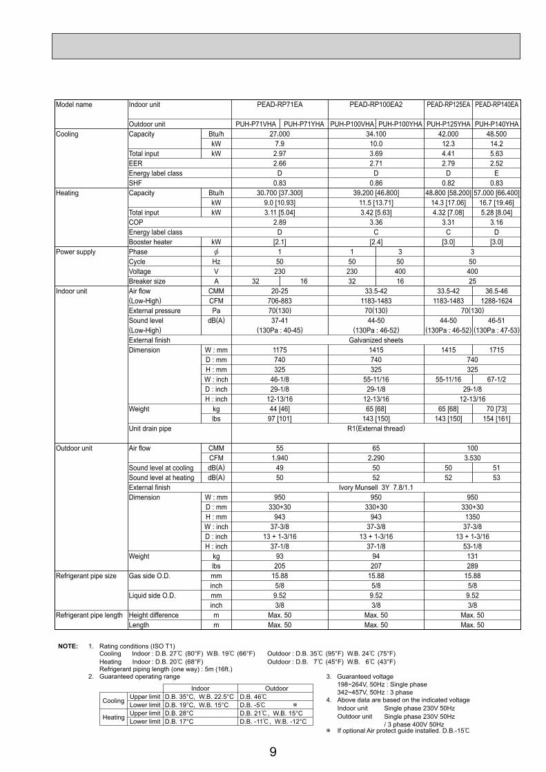
Model name Indoor unit PEAD-RP71EA PEAD-RP100EA2 PEAD-RP125EA PEAD-RP140EA
Outdoor unit PUH-P71VHA PUH-P71YHA PUH-P100VHA PUH-P100YHA PUH-P125YHA PUH-P140YHACooling Capacity Btu/h 27,000 34,100 42,000 48,500
kW 7.9 10.0 12.3 14.2Total input kW 2.97 3.69 4.41 5.63EER 2.66 2.71 2.79 2.52Energy label class D D D ESHF 0.83 0.86 0.82 0.83
Heating Capacity Btu/h 30,700 [37,300] 39,200 [46,800] 48,800 [58,200] 57,000 [66,400]kW 9.0 [10.93] 11.5 [13.71] 14.3 [17.06] 16.7 [19.46]
Total input kW 3.11 [5.04] 3.42 [5.63] 4.32 [7.08] 5.28 [8.04]COP 2.89 3.36 3.31 3.16Energy label class D C C DBooster heater kW [2.1] [2.4] [3.0] [3.0]
Power supply Phase 1 1 3 3Cycle Hz 50 50 50 50Voltage V 230 230 400 400Breaker size A 32 16 32 16 25
Indoor unit Air flow CMM 20-25 33.5-42 33.5-42 36.5-46(Low-High) CFM 706-883 1183-1483 1183-1483 1288-1624External pressure Pa 70(130) 70(130) 70(130)Sound level dB(A) 37-41 44-50 44-50 46-51(Low-High) (130Pa : 40-45) (130Pa : 46-52) (130Pa : 46-52) (130Pa : 47-53)External finish Galvanized sheetsDimension W : mm 1175 1415 1415 1715
D : mm 740 740 740H : mm 325 325 325W : inch 46-1/8 55-11/16 55-11/16 67-1/2D : inch 29-1/8 29-1/8 29-1/8H : inch 12-13/16 12-13/16 12-13/16
Weight kg 44 [46] 65 [68] 65 [68] 70 [73]lbs 97 [101] 143 [150] 143 [150] 154 [161]
Unit drain pipe R1(External thread)
Outdoor unit Air flow CMM 55 65 100CFM 1,940 2,290 3,530
Sound level at cooling dB(A) 49 50 50 51Sound level at heating dB(A) 50 52 52 53External finish Ivory Munsell 3Y 7.8/1.1Dimension W : mm 950 950 950
D : mm 330+30 330+30 330+30H : mm 943 943 1350W : inch 37-3/8 37-3/8 37-3/8D : inch 13 + 1-3/16 13 + 1-3/16 13 + 1-3/16H : inch 37-1/8 37-1/8 53-1/8
Weight kg 93 94 131lbs 205 207 289
Refrigerant pipe size Gas side O.D. mm 15.88 15.88 15.88inch 5/8 5/8 5/8
Liquid side O.D. mm 9.52 9.52 9.52inch 3/8 3/8 3/8
Refrigerant pipe length Height difference m Max. 50 Max. 50 Max. 50Length m Max. 50 Max. 50 Max. 50
NOTE: 1. Rating conditions (ISO T1)Cooling Indoor : D.B. 27 (80°F) W.B. 19 (66°F) Outdoor : D.B. 35 (95°F) W.B. 24 (75°F)Heating Indoor : D.B. 20 (68°F) Outdoor : D.B. 7 (45°F) W.B. 6 (43°F)Refrigerant piping length (one way) : 5m (16ft.)
2. Guaranteed operating range
Indoor Outdoor
Cooling Upper limit D.B. 35°C, W.B. 22.5°C D.B. 46Lower limit D.B. 19°C, W.B. 15°C D.B. -5
Heating Upper limit D.B. 28°C D.B. 21 , W.B. 15°CLower limit D.B. 17°C D.B. -11 , W.B. -12°C
4. Above data are based on the indicated voltage
If optional Air protect guide installed. D.B.-15
Indoor unit Single phase 230V 50HzSingle phase 230V 50Hz/ 3 phase 400V 50Hz
Outdoor unit
3. Guaranteed voltage 198~264V, 50Hz : Single phase 342~457V, 50Hz : 3 phase

10
Model name Indoor unit PEAD-RP71EA PEAD-RP100EA2 PEAD-RP125EA PEAD-RP140EA
Outdoor unit PU-P71VHA PU-P71YHA PU-P100VHA PU-P100YHA PU-P125YHA PU-P140YHACooling Capacity Btu/h 27,000 34,100 42,000 48,500
kW 7.9 10.0 12.3 14.2Total input kW 2.97 3.69 4.41 5.63EER 2.66 2.71 2.79 2.52Energy label class D D D ESHF 0.83 0.86 0.82 0.83
Heating Capacity Btu/h — — — —kW — — — —
Total input kW — — — —COP — — — —Energy label class — — — —Booster heater kW — — — —
Power supply Phase 1 1 3 3Cycle Hz 50 50 50 50Voltage V 230 230 400 400Breaker size A 32 16 32 16 25
Indoor unit Air flow CMM 20-25 33.5-42 33.5-42 36.5-46(Low-High) CFM 706-883 1183-1483 1183-1483 1288-1624External pressure Pa 70(130) 70(130) 70(130)Sound level dB(A) 37-41 44-50 44-50 46-51(Low-High) (130Pa : 40-45) (130Pa : 46-52) (130Pa : 46-52) (130Pa : 47-53)External finish Galvanized sheetsDimension W : mm 1175 1415 1415 1715
D : mm 740 740 740H : mm 325 325 325W : inch 46-1/8 55-11/16 55-11/16 67-1/2D : inch 29-1/8 29-1/8 29-1/8H : inch 12-13/16 12-13/16 12-13/16
Weight kg 44 65 65 70lbs 97 143 143 154
Unit drain pipe R1(External thread)
Outdoor unit Air flow CMM 55 65 100CFM 1,940 2,290 3,530
Sound level at cooling dB(A) 49 50 50 51Sound level at heating dB(A) — — — —External finish Ivory Munsell 3Y 7.8/1.1Dimension W : mm 950 950 950
D : mm 330+30 330+30 330+30H : mm 943 943 1350W : inch 37-3/8 37-3/8 37-3/8D : inch 13 + 1-3/16 13 + 1-3/16 13 + 1-3/16H : inch 37-1/8 37-1/8 53-1/8
Weight kg 93 94 131lbs 205 207 289
Refrigerant pipe size Gas side O.D. mm 15.88 15.88 15.88inch 5/8 5/8 5/8
Liquid side O.D. mm 9.52 9.52 9.52inch 3/8 3/8 3/8
Refrigerant pipe length Height difference m Max. 50 Max. 50 Max. 50Length m Max. 50 Max. 50 Max. 50
NOTE: 1. Rating conditions (ISO T1)Cooling Indoor : D.B. 27 (80°F) W.B. 19 (66°F) Outdoor : D.B. 35 (95°F) W.B. 24 (75°F)Refrigerant piping length (one way) : 5m (16ft.)
2. Guaranteed operating rangeIndoor Outdoor
Cooling Upper limit D.B. 35°C, W.B. 22.5°C D.B. 46Lower limit D.B. 19°C, W.B. 15°C D.B. -5 4. Above data are based on the indicated voltage
If optional Air protect guide installed. D.B.-15
Indoor unit Single phase 230V 50HzSingle phase 230V 50Hz/ 3 phase 400V 50Hz
Outdoor unit
3. Guaranteed voltage 198~264V, 50Hz : Single phase 342~457V, 50Hz : 3 phase

11
Model name Indoor unit PEAD-RP71GA PEAD-RP100GA
Outdoor unit PUH-P71VHA PUH-P71YHA PUH-P100VHA PUH-P100YHACooling Capacity Btu/h 27,000 33,100
kW 7.9 9.7Total input kW 2.97 3.98EER 2.66 2.44Energy label class D ESHF 0.83 0.86
Heating Capacity Btu/h 30,700 39,200kW 9.0 11.5
Total input kW 3.11 4.09COP 2.89 2.81Energy label class D DBooster heater kW — —
Power supply Phase 1 3 1 3Cycle Hz 50 50 50 50Voltage V 230 400 230 400Breaker size A 32 16 32 16
Indoor unit Air flow CMM 20-25 26.5-33(Low-High) CFM 706-883 935-1165External pressure Pa 10/50/70 10/50/70Sound level dB(A) 35-38/37-41/37-43 40-43/42-45/42-46(Low-High) (10/50/70Pa) (10/50/70Pa)External finish Galvanized sheetsDimension W : mm 1171 1411
D : mm 740H : mm 275W : inch 46-1/8 55-9/16D : inch 29-1/8H : inch 10-13/16
Weight kg 42 50lbs 93 111
Unit drain pipe O.D. mm 32inch 1-1/4
Outdoor unit Air flow CMM 55 65CFM 1,940 2,290
Sound level at cooling dB(A) 49 50Sound level at heating dB(A) 50 52External finish Ivory Munsell 3Y 7.8/1.1Dimension W : mm 950 950
D : mm 330+30 330+30H : mm 943 943W : inch 37-3/8 37-3/8D : inch 13 + 1-3/16 13 + 1-3/16H : inch 37-1/8 37-1/8
Weight kg 93 94lbs 205 207
Refrigerant pipe size Gas side O.D. mm 15.88 15.88inch 5/8 5/8
Liquid side O.D. mm 9.52 9.52inch 3/8 3/8
Refrigerant pipe length Height difference m Max. 50 Max. 50Length m Max. 50 Max. 50
NOTE: 1. Rating conditions (ISO T1)Cooling Indoor : D.B. 27 (80°F) W.B. 19 (66°F) Outdoor : D.B. 35 (95°F) W.B. 24 (75°F)Heating Indoor : D.B. 20 (68°F) Outdoor : D.B. 7 (45°F) W.B. 6 (43°F)Refrigerant piping length (one way) : 5m (16ft.)
2. Guaranteed operating range
Indoor Outdoor
Cooling Upper limit D.B. 35°C, W.B. 22.5°C D.B. 46Lower limit D.B. 19°C, W.B. 15°C D.B. -5
Heating Upper limit D.B. 28°C D.B. 21 , W.B. 15°CLower limit D.B. 17°C D.B. -11 , W.B. -12°C
4. Above data are based on the indicated voltage
If optional Air protect guide installed. D.B.-15
Indoor unit Single phase 230V 50HzSingle phase 230V 50Hz/ 3 phase 400V 50Hz
Outdoor unit
3. Guaranteed voltage 198~264V, 50Hz : Single phase 342~457V, 50Hz : 3 phase

12
Model name Indoor unit PEAD-RP71GA PEAD-RP100GA
Outdoor unit PU-P71VHA PU-P71YHA PU-P100VHA PU-P100YHACooling Capacity Btu/h 27,000 33,100
kW 7.9 9.7Total input kW 2.97 3.98EER 2.66 2.44Energy label class D ESHF 0.83 0.86
Heating Capacity Btu/h — —kW — —
Total input kW — —COP — —Energy label class — —Booster heater kW — —
Power supply Phase 1 3 1 3Cycle Hz 50 50 50 50Voltage V 230 400 230 400Breaker size A 32 16 32 16
Indoor unit Air flow CMM 20-25 26.5-33(Low-High) CFM 706-883 935-1165External pressure Pa 10/50/70 10/50/70Sound level dB(A) 35-38/37-41/37-43 40-43/42-45/42-46(Low-High) (10/50/70Pa) (10/50/70Pa)External finish Galvanized sheetsDimension W : mm 1171 1411
D : mm 740H : mm 275W : inch 46-1/8 55-9/16D : inch 29-1/8H : inch 10-13/16
Weight kg 42 50lbs 93 111
Unit drain pipe O.D. mm 32inch 1-1/4
Outdoor unit Air flow CMM 55 65CFM 1,940 2,290
Sound level at cooling dB(A) 49 50Sound level at heating dB(A) — —External finish Ivory Munsell 3Y 7.8/1.1Dimension W : mm 950 950
D : mm 330+30 330+30H : mm 943 943W : inch 37-3/8 37-3/8D : inch 13 + 1-3/16 13 + 1-3/16H : inch 37-1/8 37-1/8
Weight kg 93 94lbs 205 207
Refrigerant pipe size Gas side O.D. mm 15.88 15.88inch 5/8 5/8
Liquid side O.D. mm 9.52 9.52inch 3/8 3/8
Refrigerant pipe length Height difference m Max. 50 Max. 50Length m Max. 50 Max. 50
NOTE: 1. Rating conditions (ISO T1)Cooling Indoor : D.B. 27 (80°F) W.B. 19 (66°F) Outdoor : D.B. 35 (95°F) W.B. 24 (75°F)Refrigerant piping length (one way) : 5m (16ft.)
2. Guaranteed operating rangeIndoor Outdoor
Cooling Upper limit D.B. 35°C, W.B. 22.5°C D.B. 46Lower limit D.B. 19°C, W.B. 15°C D.B. -5 4. Above data are based on the indicated voltage
If optional Air protect guide installed. D.B.-15
Indoor unit Single phase 230V 50HzSingle phase 230V 50Hz/ 3 phase 400V 50Hz
Outdoor unit
3. Guaranteed voltage 198~264V, 50Hz : Single phase 342~457V, 50Hz : 3 phase

13
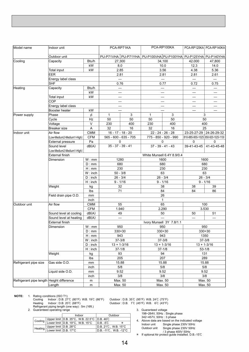
2-3. CEILING-SUSPENDED TYPEModel name Indoor unit PCA-RP71KA PCA-RP100KA PCA-RP125KA PCA-RP140KA
Outdoor unit PUH-P71VHA PUH-P71YHA PUH-P100VHA PUH-P100YHA PUH-P125YHA PUH-P140YHACooling Capacity Btu/h 27,300 34,100 42,000 47,800
kW 8.0 10.0 12.3 14.0Total input kW 2.85 3.56 4.38 5.36EER 2.81 2.81 2.81 2.61Energy label class — — — —SHF 0.76 0.77 0.72 0.75
Heating Capacity Btu/h 30,700 39,200 48,800 58,000kW 9.0 11.5 14.3 17.0
Total input kW 2.8 3.37 4.45 5.22COP 3.21 3.41 3.21 3.26Energy label class — — — —Booster heater kW — — — —
Power supply Phase 1 3 1 3 3Cycle Hz 50 50 50 50 50Voltage V 230 400 230 400 400Breaker size A 32 16 32 16 25
Indoor unit Air flow CMM 16 - 17 - 18 - 20 22 - 24 - 26 - 28 23-25-27-29(Low-Medium2-Medium1-High) CFM 565 - 600 - 635 - 705 775 - 850 - 920 - 990 810-885-955-1025External pressure Pa 0 0 0Sound level dB(A) 35 - 37 - 39 - 41 37 - 39 - 41 - 43 39-41-43-45 41-43-45-48(Low-Medium2-Medium1-High)External finish White Munsell 6.4Y 8.9/0.4Dimension W : mm 1280 1600 1600
D : mm 680 680 680H : mm 230 230 230W : inch 50 - 3/8 63 63D : inch 26 - 3/4 26 - 3/4 26 - 3/4H : inch 9 - 1/16 9 - 1/16 9 - 1/16
Weight kg 32 36 38 39lbs 71 79 84 86
Field drain pipe O.D. mm 26inch 1
Outdoor unit Air flow CMM 55 65 100CFM 1,940 2,290 3,530
Sound level at cooling dB(A) 49 50 50 51Sound level at heating dB(A) 50 52 52 53External finish Ivory Munsell 3Y 7.8/1.1Dimension W : mm 950 950 950
D : mm 330+30 330+30 330+30H : mm 943 943 1350W : inch 37-3/8 37-3/8 37-3/8D : inch 13 + 1-3/16 13 + 1-3/16 13 + 1-3/16H : inch 37-1/8 37-1/8 53-1/8
Weight kg 93 94 131lbs 205 207 289
Refrigerant pipe size Gas side O.D. mm 15.88 15.88 15.88inch 5/8 5/8 5/8
Liquid side O.D. mm 9.52 9.52 9.52inch 3/8 3/8 3/8
Refrigerant pipe length Height difference m Max. 50 Max. 50 Max. 50Length m Max. 50 Max. 50 Max. 50
24-26-29-32850-920-1025-1130
0
NOTE: 1. Rating conditions (ISO T1)Cooling Indoor : D.B. 27 (80°F) W.B. 19 (66°F) Outdoor : D.B. 35 (95°F) W.B. 24 (75°F)Heating Indoor : D.B. 20 (68°F) Outdoor : D.B. 7 (45°F) W.B. 6 (43°F)Refrigerant piping length (one way) : 5m (16ft.)
2. Guaranteed operating range
Indoor Outdoor
Cooling Upper limit D.B. 35°C, W.B. 22.5°C D.B. 46Lower limit D.B. 19°C, W.B. 15°C D.B. -5
Heating Upper limit D.B. 28°C D.B. 21 , W.B. 15°CLower limit D.B. 17°C D.B. -11 , W.B. -12°C
4. Above data are based on the indicated voltage
If optional Air protect guide installed. D.B.-15
Indoor unit Single phase 230V 50HzSingle phase 230V 50Hz/ 3 phase 400V 50Hz
Outdoor unit
3. Guaranteed voltage 198~264V, 50Hz : Single phase 342~457V, 50Hz : 3 phase
14
Model name Indoor unit PCA-RP71KA PCA-RP100KA PCA-RP125KA PCA-RP140KA
Outdoor unit PU-P71VHA PU-P71YHA PU-P100VHA PU-P100YHA PU-P125YHA PU-P140YHACooling Capacity Btu/h
kWTotal input kWEEREnergy label classSHF
Heating Capacity Btu/h — — — —kW — — — —
Total input kW — — — —COP — — — —Energy label class — — — —Booster heater kW — — — —
Power supply Phase 1 3 1 3 3Cycle Hz 50 50 50 50 50Voltage V 230 400 230 400 400Breaker size A 32 16 32 16 25
Indoor unit Air flow CMM 16 - 17 - 18 - 20 22 - 24 - 26 - 28 23-25-27-29(Low-Medium2-Medium1-High) CFM 565 - 600 - 635 - 705 775 - 850 - 920 - 990 810-885-955-1025External pressure Pa 0 0 0Sound level dB(A) 35 - 37 - 39 - 41 37 - 39 - 41 - 43 39-41-43-45 41-43-45-48(Low-Medium2-Medium1-High)External finish White Munsell 6.4Y 8.9/0.4Dimension W : mm 1280 1600 1600
D : mm 680 680 680H : mm 230 230 230W : inch 50 - 3/8 63 63D : inch 26 - 3/4 26 - 3/4 26 - 3/4H : inch 9 - 1/16 9 - 1/16 9 - 1/16
Weight kg 32 38 38 39lbs 71 84 84 86
Field drain pipe O.D. mm 26inch 1
Outdoor unit Air flow CMM 55 65 100CFM 1,940 2,290 3,530
Sound level at cooling dB(A) 49 50 50 51Sound level at heating dB(A) — — — —External finish Ivory Munsell 3Y 7.8/1.1Dimension W : mm 950 950 950
D : mm 330+30 330+30 330+30H : mm 943 943 1350W : inch 37-3/8 37-3/8 37-3/8D : inch 13 + 1-3/16 13 + 1-3/16 13 + 1-3/16H : inch 37-1/8 37-1/8 53-1/8
Weight kg 93 94 131lbs 205 207 289
Refrigerant pipe size Gas side O.D. mm 15.88 15.88 15.88inch 5/8 5/8 5/8
Liquid side O.D. mm 9.52 9.52 9.52inch 3/8 3/8 3/8
Refrigerant pipe length Height difference m Max. 50 Max. 50 Max. 50Length m Max. 50 Max. 50 Max. 50
27,300 34,100 42,000 47,8008.0 10.0 12.3 14.0
2.85 3.56 4.38 5.362.81 2.81 2.81 2.61— — — —
0.76 0.77 0.72 0.75
24-26-29-32850-920-1025-1130
0
NOTE: 1. Rating conditions (ISO T1)Cooling Indoor : D.B. 27 (80°F) W.B. 19 (66°F) Outdoor : D.B. 35 (95°F) W.B. 24 (75°F)Heating Indoor : D.B. 20 (68°F) Outdoor : D.B. 7 (45°F) W.B. 6 (43°F)Refrigerant piping length (one way) : 5m (16ft.)
2. Guaranteed operating range
Indoor Outdoor
Cooling Upper limit D.B. 35°C, W.B. 22.5°C D.B. 46Lower limit D.B. 19°C, W.B. 15°C D.B. -5
Heating Upper limit D.B. 28°C D.B. 21 , W.B. 15°CLower limit D.B. 17°C D.B. -11 , W.B. -12°C
4. Above data are based on the indicated voltage
If optional Air protect guide installed. D.B.-15
Indoor unit Single phase 230V 50HzSingle phase 230V 50Hz/ 3 phase 400V 50Hz
Outdoor unit
3. Guaranteed voltage 198~264V, 50Hz : Single phase 342~457V, 50Hz : 3 phase

15
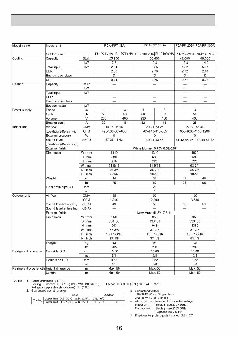
Model name Indoor unit PCA-RP71GA PCA-RP100GA PCA-RP125GA PCA-RP140GA
Outdoor unit PUH-P71VHA PUH-P71YHA PUH-P100VHA PUH-P100YHA PUH-P125YHA PUH-P140YHACooling Capacity Btu/h 25,900 33,400 42,000 48,500
kW 7.6 9.8 12.3 14.2Total input kW 2.84 3.55 4.52 5.44EER 2.68 2.76 2.72 2.61Energy label class D D D DSHF 0.74 0.75 0.77 0.75
Heating Capacity Btu/h 30,000 [36,600] 39,200 [47,700] 48,800 [58,200] 58,000 [67,400]kW 8.8 [10.73] 11.5 [13.98] 14.3 [17.06] 17.0 [19.76]
Total input kW 2.76 [4.69] 3.45 [5.93] 4.72 [7.48] 5.22 [7.98]COP 3.19 3.33 3.03 3.26Energy label class D C D CBooster heater kW [2.1] [2.7] [3.0] [3.0]
Power supply Phase 1 3 1 3 3Cycle Hz 50 50 50 50 50Voltage V 230 400 230 400 400Breaker size A 32 16 32 16 25
Indoor unit Air flow CMM 14-15-16-18 20-21-23-25 27-30-32-34(Low-Medium2-Medium1-High) CFM 495-530-565-635 705-840-810-885 955-1060-1130-1200External pressure Pa 0 0 0Sound level dB(A) 37-39-41-43 40-41-43-45 41-43-45-46 42-44-46-48(Low-Medium2-Medium1-High)External finish White Munsell 0.70Y 8.59/0.97Dimension W : mm 1310 1310 1620
D : mm 680 680 680H : mm 210 270 270W : inch 51-9/16 51-9/16 63-3/4D : inch 26-3/4 26-3/4 26-3/4H : inch 8-1/4 10-5/8 10-5/8
Weight kg 34 [36] 37 [39.5] 43 [46] 45 [48]lbs 75 [79] 82 [87] 95 [101] 99 [106]
Field drain pipe O.D. mm 26inch 1
Outdoor unit Air flow CMM 55 65 100CFM 1,940 2,290 3,530
Sound level at cooling dB(A) 49 50 50 51Sound level at heating dB(A) 50 52 52 53External finish Ivory Munsell 3Y 7.8/1.1Dimension W : mm 950 950 950
D : mm 330+30 330+30 330+30H : mm 943 943 1350W : inch 37-3/8 37-3/8 37-3/8D : inch 13 + 1-3/16 13 + 1-3/16 13 + 1-3/16H : inch 37-1/8 37-1/8 53-1/8
Weight kg 93 94 131lbs 205 207 289
Refrigerant pipe size Gas side O.D. mm 15.88 15.88 15.88inch 5/8 5/8 5/8
Liquid side O.D. mm 9.52 9.52 9.52inch 3/8 3/8 3/8
Refrigerant pipe length Height difference m Max. 50 Max. 50 Max. 50Length m Max. 50 Max. 50 Max. 50
NOTE: 1. Rating conditions (ISO T1)Cooling Indoor : D.B. 27 (80°F) W.B. 19 (66°F) Outdoor : D.B. 35 (95°F) W.B. 24 (75°F)Heating Indoor : D.B. 20 (68°F) Outdoor : D.B. 7 (45°F) W.B. 6 (43°F)Refrigerant piping length (one way) : 5m (16ft.)
2. Guaranteed operating range
Indoor Outdoor
Cooling Upper limit D.B. 35°C, W.B. 22.5°C D.B. 46Lower limit D.B. 19°C, W.B. 15°C D.B. -5
Heating Upper limit D.B. 28°C D.B. 21 , W.B. 15°CLower limit D.B. 17°C D.B. -11 , W.B. -12°C
4. Above data are based on the indicated voltage
If optional Air protect guide installed. D.B.-15
Indoor unit Single phase 230V 50HzSingle phase 230V 50Hz/ 3 phase 400V 50Hz
Outdoor unit
3. Guaranteed voltage 198~264V, 50Hz : Single phase 342~457V, 50Hz : 3 phase
16
Model name Indoor unit PCA-RP71GA PCA-RP100GA PCA-RP125GA PCA-RP140GA
Outdoor unit PU-P71VHA PU-P71YHA PU-P100VHA PU-P100YHA PU-P125YHA PU-P140YHACooling Capacity Btu/h 25,900 33,400 42,000 48,500
kW 7.6 9.8 12.3 14.2Total input kW 2.84 3.55 4.52 5.44EER 2.68 2.76 2.72 2.61Energy label class D D D DSHF 0.74 0.75 0.77 0.75
Heating Capacity Btu/h — — — —kW — — — —
Total input kW — — — —COP — — — —Energy label class — — — —Booster heater kW — — — —
Power supply Phase 1 3 1 3 3Cycle Hz 50 50 50 50 50Voltage V 230 400 230 400 400Breaker size A 32 16 32 16 25
Indoor unit Air flow CMM 14-15-16-18 20-21-23-25 27-30-32-34(Low-Medium2-Medium1-High) CFM 495-530-565-635 705-840-810-885 955-1060-1130-1200External pressure Pa 0 0 0Sound level dB(A) 37-39-41-43 40-41-43-45 41-43-45-46 42-44-46-48(Low-Medium2-Medium1-High)External finish White Munsell 0.70Y 8.59/0.97Dimension W : mm 1310 1310 1620
D : mm 680 680 680H : mm 210 270 270W : inch 51-9/16 51-9/16 63-3/4D : inch 26-3/4 26-3/4 26-3/4H : inch 8-1/4 10-5/8 10-5/8
Weight kg 34 37 43 45lbs 75 82 95 99
Field drain pipe O.D. mm 26inch 1
Outdoor unit Air flow CMM 55 65 100CFM 1,940 2,290 3,530
Sound level at cooling dB(A) 49 50 50 51Sound level at heating dB(A) — — — —External finish Ivory Munsell 3Y 7.8/1.1Dimension W : mm 950 950 950
D : mm 330+30 330+30 330+30H : mm 943 943 1350W : inch 37-3/8 37-3/8 37-3/8D : inch 13 + 1-3/16 13 + 1-3/16 13 + 1-3/16H : inch 37-1/8 37-1/8 53-1/8
Weight kg 93 94 131lbs 205 207 289
Refrigerant pipe size Gas side O.D. mm 15.88 15.88 15.88inch 5/8 5/8 5/8
Liquid side O.D. mm 9.52 9.52 9.52inch 3/8 3/8 3/8
Refrigerant pipe length Height difference m Max. 50 Max. 50 Max. 50Length m Max. 50 Max. 50 Max. 50
NOTE: 1. Rating conditions (ISO T1)Cooling Indoor : D.B. 27 (80°F) W.B. 19 (66°F) Outdoor : D.B. 35 (95°F) W.B. 24 (75°F)Refrigerant piping length (one way) : 5m (16ft.)
2. Guaranteed operating rangeIndoor Outdoor
Cooling Upper limit D.B. 35°C, W.B. 22.5°C D.B. 46Lower limit D.B. 19°C, W.B. 15°C D.B. -5 4. Above data are based on the indicated voltage
If optional Air protect guide installed. D.B.-15
Indoor unit Single phase 230V 50HzSingle phase 230V 50Hz/ 3 phase 400V 50Hz
Outdoor unit
3. Guaranteed voltage 198~264V, 50Hz : Single phase 342~457V, 50Hz : 3 phase

17
Model name Indoor unit PCA-RP71HA PCA-RP125HA
Outdoor unit PUH-P71VHA PUH-P71YHA PUH-P125YHACooling Capacity Btu/h 25,600 42,000
kW 7.5 12.3Total input kW 2.79 4.55EER 2.69 2.70Energy label class — —SHF 0.74 0.77
Heating Capacity Btu/h 30,400 48,800kW 8.9 14.3
Total input kW 2.85 5.01COP 3.12 2.85Energy label class — —Booster heater kW — —
Power supply Phase 1 3 3Cycle Hz 50 50 50Voltage V 230 400 400Breaker size A 32 16 25
Indoor unit Air flow CMM 17-19 30-38(Low-High) CFM 600-670 1060-1350External pressure Pa 0 0Sound level dB(A) 34-38 44-50(Low-High)External finish Stainless steelDimension W : mm 1136 1520
D : mm 650H : mm 280W : inch 44-3/4 59-7/8D : inch 25-5/8H : inch 11
Weight kg 41 56lbs 90 124
Unit drain pipe O.D. mm 26inch 1
Outdoor unit Air flow CMM 55 100CFM 1,940 3,530
Sound level at cooling dB(A) 49 50Sound level at heating dB(A) 50 52External finish Ivory Munsell 3Y 7.8/1.1Dimension W : mm 950 950
D : mm 330+30 330+30H : mm 943 1350W : inch 37-3/8 37-3/8D : inch 13 + 1-3/16 13 + 1-3/16H : inch 37-1/8 53-1/8
Weight kg 93 131lbs 205 289
Refrigerant pipe size Gas side O.D. mm 15.88 15.88inch 5/8 5/8
Liquid side O.D. mm 9.52 9.52inch 3/8 3/8
Refrigerant pipe length Height difference m Max. 50 Max. 50Length m Max. 50 Max. 50
NOTE: 1. Rating conditions (ISO T1)Cooling Indoor : D.B. 27 (80°F) W.B. 19 (66°F) Outdoor : D.B. 35 (95°F) W.B. 24 (75°F)Heating Indoor : D.B. 20 (68°F) Outdoor : D.B. 7 (45°F) W.B. 6 (43°F)Refrigerant piping length (one way) : 5m (16ft.)
2. Guaranteed operating range
Indoor Outdoor
Cooling Upper limit D.B. 35°C, W.B. 22.5°C D.B. 46Lower limit D.B. 19°C, W.B. 15°C D.B. -5
Heating Upper limit D.B. 28°C D.B. 21 , W.B. 15°CLower limit D.B. 17°C D.B. -11 , W.B. -12°C
4. Above data are based on the indicated voltageIndoor unit Single phase 230V 50Hz
Single phase 230V 50Hz/ 3 phase 400V 50Hz
Outdoor unit
3. Guaranteed voltage 198~264V, 50Hz : Single phase 342~457V, 50Hz : 3 phase

18
Model name Indoor unit PCA-RP71HA PCA-RP125HA
Outdoor unit PU-P71VHA PU-P71YHA PU-P125YHACooling Capacity Btu/h 25,600 42,000
kW 7.5 12.3Total input kW 2.79 4.55EER 2.69 2.70Energy label class — —SHF 0.74 0.77
Heating Capacity Btu/h — —kW — —
Total input kW — —COP — —Energy label class — —Booster heater kW — —
Power supply Phase 1 3 3Cycle Hz 50 50 50Voltage V 230 400 400Breaker size A 32 16 25
Indoor unit Air flow CMM 17-19 30-38(Low-High) CFM 600-670 1060-1350External pressure Pa 0 0Sound level dB(A) 34-38 44-50(Low-High)External finish Stainless steelDimension W : mm 1136 1520
D : mm 650H : mm 280W : inch 44-3/4 59-7/8D : inch 25-5/8H : inch 11
Weight kg 41 56lbs 90 124
Field drain pipe O.D. mm 26inch 1
Outdoor unit Air flow CMM 55 100CFM 1,940 3,530
Sound level at cooling dB(A) 49 50Sound level at heating dB(A) — —External finish Ivory Munsell 3Y 7.8/1.1Dimension W : mm 950 950
D : mm 330+30 330+30H : mm 943 1350W : inch 37-3/8 37-3/8D : inch 13 + 1-3/16 13 + 1-3/16H : inch 37-1/8 53-1/8
Weight kg 93 131lbs 205 289
Refrigerant pipe size Gas side O.D. mm 15.88 15.88inch 5/8 5/8
Liquid side O.D. mm 9.52 9.52inch 3/8 3/8
Refrigerant pipe length Height difference m Max. 50 Max. 50Length m Max. 50 Max. 50
NOTE: 1. Rating conditions (ISO T1)Cooling Indoor : D.B. 27 (80°F) W.B. 19 (66°F) Outdoor : D.B. 35 (95°F) W.B. 24 (75°F)Refrigerant piping length (one way) : 5m (16ft.)
2. Guaranteed operating rangeIndoor Outdoor
Cooling Upper limit D.B. 35°C, W.B. 22.5°C D.B. 46Lower limit D.B. 19°C, W.B. 15°C D.B. -5 4. Above data are based on the indicated voltage
If optional Air protect guide installed. D.B.-15
Indoor unit Single phase 230V 50HzSingle phase 230V 50Hz/ 3 phase 400V 50Hz
Outdoor unit
3. Guaranteed voltage 198~264V, 50Hz : Single phase 342~457V, 50Hz : 3 phase

19
2-4. WALL-MOUNTED TYPEModel name Indoor unit PKA-RP71KAL PKA-RP100KAL
Outdoor unit PUH-P71VHA PUH-P71YHA PUH-P100VHA PUH-P100YHACooling Capacity Btu/h 27,000 33,400
kW 7.9 9.8Total input kW 2.84 3.50EER 2.78 2.80Energy label class — —SHF 0.75 0.73
Heating Capacity Btu/h 30,000 39,200kW 8.8 11.5
Total input kW 3.08 3.47COP 2.86 3.31Energy label class — —Booster heater kW — —
Power supply Phase 1 3 1 3Cycle Hz 50 50 50 50Voltage V 230 400 230 400Breaker size A 32 16 32 16
Indoor unit Air flow CMM 18 - 20 - 22 20 - 23 - 26(Low-Middle-High) CFM 635 - 705 - 780 705 - 810 - 920External pressure Pa 0Sound level dB(A) 39 - 42 - 45 41 - 45 - 49(Low-Middle-High)External finish Munsell 1.0Y 9.2/0.2Dimension W : mm 1170
D : mm 295H : mm 365W : inch 46 - 1/16D : inch 11 - 5/8H : inch 14 - 3/8
Weight kg 21lbs 46
Field drain pipe I.D. mm 16inch 5/8
Outdoor unit Air flow CMM 55 65CFM 1,940 2,290
Sound level at cooling dB(A) 49 50Sound level at heating dB(A) 50 52External finish Ivory Munsell 3Y 7.8/1.1Dimension W : mm 950 950
D : mm 330+30 330+30H : mm 943 943W : inch 37-3/8 37-3/8D : inch 13 + 1-3/16 13 + 1-3/16H : inch 37-1/8 37-1/8
Weight kg 93 94lbs 205 207
Refrigerant pipe size Gas side O.D. mm 15.88 15.88inch 5/8 5/8
Liquid side O.D. mm 9.52 9.52inch 3/8 3/8
Refrigerant pipe length Height difference m Max. 50 Max. 50Length m Max. 50 Max. 50
NOTE: 1. Rating conditions (ISO T1)Cooling Indoor : D.B. 27 (80°F) W.B. 19 (66°F) Outdoor : D.B. 35 (95°F) W.B. 24 (75°F)Refrigerant piping length (one way) : 5m (16ft.)
2. Guaranteed operating rangeIndoor Outdoor
Cooling Upper limit D.B. 35°C, W.B. 22.5°C D.B. 46Lower limit D.B. 19°C, W.B. 15°C D.B. -5 4. Above data are based on the indicated voltage
If optional Air protect guide installed. D.B.-15
Indoor unit Single phase 230V 50HzSingle phase 230V 50Hz/ 3 phase 400V 50Hz
Outdoor unit
3. Guaranteed voltage 198~264V, 50Hz : Single phase 342~457V, 50Hz : 3 phase

20
Model name Indoor unit PKA-RP71KAL PKA-RP100KALOutdoor unit PU-P71VHA PU-P71YHA PU-P100VHA PU-P100YHA
Cooling Capacity Btu/h 27,000 33,400kW 7.9 9.8
Total input kW 2.84 3.50EER 2.78 2.80Energy label class — —SHF 0.77 0.77
Heating Capacity Btu/h — —kW — —
Total input kW — —COP — —Energy label class — —Booster heater kW — —
Power supply Phase 1 3 1 3Cycle Hz 50 50 50 50Voltage V 230 400 230 400Breaker size A 32 16 32 16
Indoor unit Air flow CMM 18 - 20 - 22 20 - 23 - 26(Low-Middle-High) CFM 635 - 705 - 780 705 - 810 - 920External pressure Pa 0Sound level dB(A) 39 - 42 - 45 41 - 45 - 49(Low-Middle-High)External finish Munsell 1.0Y 9.2/0.2Dimension W : mm 1170
D : mm 295H : mm 365W : inch 46 - 1/16D : inch 11 - 5/8H : inch 14 - 3/8
Weight kg 21lbs 46
Field drain pipe I.D. mm 16inch 5/8
Outdoor unit Air flow CMM 55 65CFM 1,940 2,290
Sound level at cooling dB(A) 49 50Sound level at heating dB(A) — —External finish Ivory Munsell 3Y 7.8/1.1Dimension W : mm 950 950
D : mm 330+30 330+30H : mm 943 943W : inch 37-3/8 37-3/8D : inch 13 + 1-3/16 13 + 1-3/16H : inch 37-1/8 37-1/8
Weight kg 93 94lbs 205 207
Refrigerant pipe size Gas side O.D. mm 15.88 15.88inch 5/8 5/8
Liquid side O.D. mm 9.52 9.52inch 3/8 3/8
Refrigerant pipe length Height difference m Max. 50 Max. 50Length m Max. 50 Max. 50
NOTE: 1. Rating conditions (ISO T1)Cooling Indoor : D.B. 27 (80°F) W.B. 19 (66°F) Outdoor : D.B. 35 (95°F) W.B. 24 (75°F)Refrigerant piping length (one way) : 5m (16ft.)
2. Guaranteed operating rangeIndoor Outdoor
Cooling Upper limit D.B. 35°C, W.B. 22.5°C D.B. 46Lower limit D.B. 19°C, W.B. 15°C D.B. -5 4. Above data are based on the indicated voltage
If optional Air protect guide installed. D.B.-15
Indoor unit Single phase 230V 50HzSingle phase 230V 50Hz/ 3 phase 400V 50Hz
Outdoor unit
3. Guaranteed voltage 198~264V, 50Hz : Single phase 342~457V, 50Hz : 3 phase

21
Model name Indoor unit PKA-RP71FAL PKA-RP100FAL
Outdoor unit PUH-P71VHA PUH-P71YHA PUH-P100VHA PUH-P100YHACooling Capacity Btu/h 27,000 33,400
kW 7.9 9.8Total input kW 2.84 3.50EER 2.78 2.80Energy label class D DSHF 0.77 0.77
Heating Capacity Btu/h 30,000 [36,600] 39,200 [46,800]kW 8.8 [10.73] 11.5 [13.71]
Total input kW 3.08 [5.01] 3.47 [5.68]COP 2.86 3.31Energy label class D DBooster heater kW [2.1] [2.4]
Power supply Phase 1 3 1 3Cycle Hz 50 50 50 50Voltage V 230 400 230 400Breaker size A 32 16 32 16
Indoor unit Air flow CMM 15-20 22-28(Low-High) CFM 530-705 780-990External pressure Pa 0Sound level dB(A) 39-45 41-46(Low-High)External finish Munsell 3.4Y 7.7/0.8Dimension W : mm 1400 1680
D : mm 235H : mm 340W : inch 55-1/8 66-1/8D : inch 9-1/4H : inch 13-3/8
Weight kg 24 [26] 28 [30]lbs 53 [57] 62 [66]
Filed drain pipe I.D. mm 20inch 13/16
Outdoor unit Air flow CMM 55 65CFM 1,940 2,290
Sound level at cooling dB(A) 49 50Sound level at heating dB(A) 50 52External finish Ivory Munsell 3Y 7.8/1.1Dimension W : mm 950 950
D : mm 330+30 330+30H : mm 943 943W : inch 37-3/8 37-3/8D : inch 13 + 1-3/16 13 + 1-3/16H : inch 37-1/8 37-1/8
Weight kg 93 94lbs 205 207
Refrigerant pipe size Gas side O.D. mm 15.88 15.88inch 5/8 5/8
Liquid side O.D. mm 9.52 9.52inch 3/8 3/8
Refrigerant pipe length Height difference m Max. 50 Max. 50Length m Max. 50 Max. 50
NOTE: 1. Rating conditions (ISO T1)Cooling Indoor : D.B. 27 (80°F) W.B. 19 (66°F) Outdoor : D.B. 35 (95°F) W.B. 24 (75°F)Refrigerant piping length (one way) : 5m (16ft.)
2. Guaranteed operating rangeIndoor Outdoor
Cooling Upper limit D.B. 35°C, W.B. 22.5°C D.B. 46Lower limit D.B. 19°C, W.B. 15°C D.B. -5 4. Above data are based on the indicated voltage
If optional Air protect guide installed. D.B.-15
Indoor unit Single phase 230V 50HzSingle phase 230V 50Hz/ 3 phase 400V 50Hz
Outdoor unit
3. Guaranteed voltage 198~264V, 50Hz : Single phase 342~457V, 50Hz : 3 phase

22
Model name Indoor unit PKA-RP71FAL PKA-RP100FALOutdoor unit PU-P71VHA PU-P71YHA PU-P100VHA PU-P100YHA
Cooling Capacity Btu/h 27,000 33,400kW 7.9 9.8
Total input kW 2.84 3.50EER 2.78 2.80Energy label class D DSHF 0.77 0.77
Heating Capacity Btu/h — —kW — —
Total input kW — —COP — —Energy label class — —Booster heater kW — —
Power supply Phase 1 3 1 3Cycle Hz 50 50 50 50Voltage V 230 400 230 400Breaker size A 32 16 32 16
Indoor unit Air flow CMM 15-20 22-28(Low-High) CFM 530-705 780-990External pressure Pa 0Sound level dB(A) 39-45 41-46(Low-High)External finish Munsell 3.4Y 7.7/0.8Dimension W : mm 1400 1680
D : mm 235H : mm 340W : inch 55-1/8 66-1/8D : inch 9-1/4H : inch 13-3/8
Weight kg 24 28lbs 53 62
Field drain pipe I.D. mm 20inch 13/16
Outdoor unit Air flow CMM 55 65CFM 1,940 2,290
Sound level at cooling dB(A) 49 50Sound level at heating dB(A) — —External finish Ivory Munsell 3Y 7.8/1.1Dimension W : mm 950 950
D : mm 330+30 330+30H : mm 943 943W : inch 37-3/8 37-3/8D : inch 13 + 1-3/16 13 + 1-3/16H : inch 37-1/8 37-1/8
Weight kg 93 94lbs 205 207
Refrigerant pipe size Gas side O.D. mm 15.88 15.88inch 5/8 5/8
Liquid side O.D. mm 9.52 9.52inch 3/8 3/8
Refrigerant pipe length Height difference m Max. 50 Max. 50Length m Max. 50 Max. 50
NOTE: 1. Rating conditions (ISO T1)Cooling Indoor : D.B. 27 (80°F) W.B. 19 (66°F) Outdoor : D.B. 35 (95°F) W.B. 24 (75°F)Refrigerant piping length (one way) : 5m (16ft.)
2. Guaranteed operating rangeIndoor Outdoor
Cooling Upper limit D.B. 35°C, W.B. 22.5°C D.B. 46Lower limit D.B. 19°C, W.B. 15°C D.B. -5 4. Above data are based on the indicated voltage
If optional Air protect guide installed. D.B.-15
Indoor unit Single phase 230V 50HzSingle phase 230V 50Hz/ 3 phase 400V 50Hz
Outdoor unit
3. Guaranteed voltage 198~264V, 50Hz : Single phase 342~457V, 50Hz : 3 phase

23
Model name Indoor unit PSA-RP71GA PSA-RP100GA PSA-RP125GA PSA-RP140GA
Outdoor unit PUH-P71VHA PUH-P71YHA PUH-P100VHA PUH-P100YHA PUH-P125YHA PUH-P140YHACooling Capacity Btu/h 25,900 34,100 42,000 47,800
kW 7.6 10.0 12.3 14.0Total input kW 2.88 3.66 4.54 5.53EER 2.64 2.73 2.71 2.53Energy label class — — — —SHF 0.73 0.81 0.75 0.74
Heating Capacity Btu/h 30,700 [37,300] 39,200 [47,700] 48,800 [58,200] 58,000 [67,400]kW 9.0 [10.93] 11.5 [13.98] 14.3 [17.06] 17.0 [19.76]
Total input kW 2.85 [4.78] 3.42 [5.90] 4.41 [7.17] 5.47 [8.23]COP 3.16 3.36 3.24 3.11Energy label class — — — —Booster heater kW [2.1] [2.7] [3.0] [3.0]
Power supply Phase 1 3 1 3 3Cycle Hz 50 50 50 50 50Voltage V 230 400 230 400 400Breaker size A 32 16 32 16 25
Indoor unit Air flow CMM 15-18 24-31 26-33 27-35(Low-High) CFM 530-635 850-1060 920-1165 955-1240External pressure Pa 0Sound level dB(A) 40-45 44-49 46-51 47-52(Low-High)External finish White Munsell 0.70Y 8.59/0.97 White Munsell 0.70Y 8.59/0.97 White Munsell 0.70Y 8.59/0.97Dimension W : mm 600 600 600
D : mm 270 350 350H : mm 1900 1900 1900W : inch 23-5/8 23-5/8 23-5/8D : inch 10-5/8 13-3/4 13-3/4H : inch 74-13/16 74-13/16 74-13/16
Weight kg 43 [45] 51 [53] 51 [53] 53 [55]lbs 95 [99] 112 [117] 112 [117] 117 [121]
Field drain pipe I.D. mm 20 20 20inch 13/16 13/16 13/16
Outdoor unit Air flow CMM 55 65 100CFM 1,940 2,290 3,530
Sound level at cooling dB(A) 49 50 50 51Sound level at heating dB(A) 50 52 52 53External finish Ivory Munsell 3Y 7.8/1.1Dimension W : mm 950 950 950
D : mm 330+30 330+30 330+30H : mm 943 943 1350W : inch 37-3/8 37-3/8 37-3/8D : inch 13 + 1-3/16 13 + 1-3/16 13 + 1-3/16H : inch 37-1/8 37-1/8 53-1/8
Weight kg 93 94 131lbs 205 207 289
Refrigerant pipe size Gas side O.D. mm 15.88 15.88 15.88inch 5/8 5/8 5/8
Liquid side O.D. mm 9.52 9.52 9.52inch 3/8 3/8 3/8
Refrigerant pipe length Height difference m Max. 50 Max. 50 Max. 50Length m Max. 50 Max. 50 Max. 50
NOTE: 1. Rating conditions (ISO T1)Cooling Indoor : D.B. 27 (80°F) W.B. 19 (66°F) Outdoor : D.B. 35 (95°F) W.B. 24 (75°F)Refrigerant piping length (one way) : 5m (16ft.)
2. Guaranteed operating rangeIndoor Outdoor
Cooling Upper limit D.B. 35°C, W.B. 22.5°C D.B. 46Lower limit D.B. 19°C, W.B. 15°C D.B. -5 4. Above data are based on the indicated voltage
If optional Air protect guide installed. D.B.-15
Indoor unit Single phase 230V 50HzSingle phase 230V 50Hz/ 3 phase 400V 50Hz
Outdoor unit
3. Guaranteed voltage 198~264V, 50Hz : Single phase 342~457V, 50Hz : 3 phase
2-5. FLOOR STANDING TYPE

24
Model name Indoor unit PSA-RP71GA PSA-RP100GA PSA-RP125GA PSA-RP140GA
Outdoor unit PU-P71VHA PU-P71YHA PU-P100VHA PU-P100YHA PU-P125YHA PU-P140YHACooling Capacity Btu/h 25,900 34,100 42,000 47,800
kW 7.6 10.0 12.3 14.0Total input kW 2.88 3.66 4.54 5.53EER 2.64 2.73 2.71 2.53Energy label class — — — —SHF 0.73 0.81 0.75 0.74
Heating Capacity Btu/h — — — —kW — — — —
Total input kW — — — —COP — — — —Energy label class — — — —Booster heater kW — — — —
Power supply Phase 1 3 1 3 3Cycle Hz 50 50 50 50 50Voltage V 230 400 230 400 400Breaker size A 32 16 32 16 25
Indoor unit Air flow CMM 15-18 24-31 26-33 27-35(Low-High) CFM 530-635 850-1060 920-1165 955-1240External pressure Pa 0Sound level dB(A) 40-45 44-49 46-51 47-52(Low-High)External finish White Munsell 0.70Y 8.59/0.97 White Munsell 0.70Y 8.59/0.97 White Munsell 0.70Y 8.59/0.97Dimension W : mm 600 600 600
D : mm 270 350 350H : mm 1900 1900 1900W : inch 23-5/8 23-5/8 23-5/8D : inch 10-5/8 13-3/4 13-3/4H : inch 74-13/16 74-13/16 74-13/16
Weight kg 43 51 51 53lbs 95 112 112 117
Field drain pipe I.D. mm 20 20 20inch 13/16 13/16 13/16
Outdoor unit Air flow CMM 55 65 100CFM 1,940 2,290 3,530
Sound level at cooling dB(A) 49 50 50 51Sound level at heating dB(A) — — — —External finish Ivory Munsell 3Y 7.8/1.1Dimension W : mm 950 950 950
D : mm 330+30 330+30 330+30H : mm 943 943 1350W : inch 37-3/8 37-3/8 37-3/8D : inch 13 + 1-3/16 13 + 1-3/16 13 + 1-3/16H : inch 37-1/8 37-1/8 53-1/8
Weight kg 93 94 131lbs 205 207 289
Refrigerant pipe size Gas side O.D. mm 15.88 15.88 15.88inch 5/8 5/8 5/8
Liquid side O.D. mm 9.52 9.52 9.52inch 3/8 3/8 3/8
Refrigerant pipe length Height difference m Max. 50 Max. 50 Max. 50Length m Max. 50 Max. 50 Max. 50
NOTE: 1. Rating conditions (ISO T1)Cooling Indoor : D.B. 27 (80°F) W.B. 19 (66°F) Outdoor : D.B. 35 (95°F) W.B. 24 (75°F)Refrigerant piping length (one way) : 5m (16ft.)
2. Guaranteed operating rangeIndoor Outdoor
Cooling Upper limit D.B. 35°C, W.B. 22.5°C D.B. 46Lower limit D.B. 19°C, W.B. 15°C D.B. -5 4. Above data are based on the indicated voltage
If optional Air protect guide installed. D.B.-15
Indoor unit Single phase 230V 50HzSingle phase 230V 50Hz/ 3 phase 400V 50Hz
Outdoor unit
3. Guaranteed voltage 198~264V, 50Hz : Single phase 342~457V, 50Hz : 3 phase

2525
OUTLINES AND DIMENSIONS3
37728460 ( )
Ceiling hole
Branch duct hole
Drain pipeconnected to VP-25
Ceiling
Grille
Drain hole
Models
Auto vane(Air outlet)
Air intake grille
Ceiling
Cut out hole
Cut out hole
Cut out hole
Burring hole pitch
Burring hole pitch Burring hole
Burring hole
Power supply wire,Indoor unit/Outdoor unit connecting wire entry
Indoor unit/Outdoor unit connecting terminal block
Indoor power supplyterminal block(Option part)
Control wire entry
Air intake hole
Air in
take h
ole
Air outlet hole
Air o
utlet
hole
Connected the attacheddrain socket.
Keep approximately 10 to 15mm spacebetween unit ceiling and ceiling slab.
Branch duct hole
Fresh air intake hole
Ceilin
g hole
Susp
ensio
n bolt
pitch
Suspension bolt pitch
Remote controller terminal block
Suspension bolt M10 or W3/8
(7.5)
(7.5)
605
+35
-
5
620
DEFROST/STAND BY lampReceiverOperation lamp
In case of standard grille : PLP-6BA / PLP-6BAMD
In case of wireless remote controller : PLP-6BALM Auto GrilleAir intake grille up/down discharge
Emergency operation switch<Cooling>andEmergency Up/Down switch<Up>
160
160
500
500
597
83 36
950
8336
950
597
A17
+5 0
B35
190
156
105
140
50~7
0
160
840
150
90 C D
840187.5
20~45 860~910 20~45
810
20~4
586
0~91
020
~45
24 160
M
M
M
M
120
120
175
125
167
158
Vane motor
2
1
Drain pump clean holeand Drain emergency drainage hole
130
100
70
155
350
90 100 100 90
BA C D E
241 258
80
87
74400
29885 77
440281
21
Refrigerant pipe··· 6.35Flared connection···1/4F
Refrigerant pipe··· 9.52Flared connection···3/8F
Refrigerant pipe··· 12.7Flared connection···1/2F
Refrigerant pipe··· 15.88Flared connection···5/8F
Refrigerant pipe6.35 / 9.52
Flared connection 1/4F / 3/8F (compatible)
PLA-RP35/50BA
PLA-RP60BA
PLA-RP71BA
PLA-RP100,125,140BAPLA-RP140BA2
Detail drawing of fresh air intake hole
Detail connecting of Branch duct(Both aspects)
3- 2.8
14- 2.8
150
100
Emergency operation switch<Heating>andEmergency Up/Down switch<Down>
In case of Auto-Grille : PLP-6BAJ
Suspension bolt lower edge
170
Ceiling
Air intake grilleMa
x. 4.0
m
L.L Filter
Ceiling
Grille
Indoor unit
1500mmor more
1000m
mor m
ore 3000mm or more 1800mm or morefrom floorFor high attachment
Indoor unit
Obstacle
Floor
Note1. Please choose the Grille from a standard grille, Auto-Grille. 2. As for drain pipe, please use VP-25(O.D. 32 PVC TUBE). Drain pump inclusion. Raise is max 850mm from the ceiling. 3. As for suspension bolt, please use M10 or W3/8. (Procured at local site) 4. Electrical box may be removed for the service purpose. Make sure to slack the electrical wire little bit for control/ power wires connection. 5. The height of the indoor unit is able to be adjusted with the grille attached. 6. For the installation of the optional high efficiency filter or optional multi-functional casement. 1) Requires E or more space between transom and ceiling for the installation. 2) Add 135 mm to the dimensions marked on the figure. 3) Optional high efficiency filter must be used jointly with optional multi functional casement.
7. When installing the branch ducts, be sure to insulate adequately. Otherwise condensation and dripping may occur. (It becomes the cause of dew drops/Water dew.)
8. As for necessary installation/service space, please refer to the under at figure.
PLA-RP35BA PLA-RP50BA PLA-RP60BA PLA-RP71BAPLA-RP100BA PLARP125BA PLA-RP140BA PLA-RP140BA2 Unit : mm

26
PLA-RP60,71AA
PLA-RP35,50AA
Models
PLA-RP100,125,140AA2
241
281
A
258
298
B
80
84
C
ReceiverOperation lamp
DEFROST/STAND BY lamp
Emergency operation switch (cooling)
A (WIRELESS PANEL)
Emergency operation switch (heating)
Branch duct hole(Cut out hole)
175
150
14 - 2.8Burring hole
350
90
70
100 100 90
100
130
155
167
Sus
pens
ion
bolt
pitc
h
Cei
ling
hole
Branchduct hole
Suspension bolt pitch
Ceiling hole
840
197 159
159
605
159
192
98 89 C
840
860
- 910
20 -
4520
- 45
20 - 4520 - 45
Fresh air intake
Branch duct hole
860 - 910810
159
16
Terminal block
Drain pipeVP-25connection(O.D. 32)
Ceiling surfacePower line entrySuspension bolt lower edge
Suspension bolt M10or W3/8
Control wire entry
Feeding hole(Drain pump)
37428660
17+5 0 30
190
170
140
50 -
70
105
AB
1
2
High efficiency filter& Fresh air intake casement (option)
17+5 0
135
Air outlet hole
Vane motor
Auto vane
Drain hole
Grille
Air
outle
t hol
e
Air
inta
ke h
ole
411
Air intake holeAir intake grille 577
77 51
M
M
M
A
M
950
5177
950
577
411
RP35, 50
Use the current nuts meeting the pipe size of the outdoor unit.Available pipe size
Factory flare nut attachment to the heat-exchanger.
LIQUID SIDE
GAS SIDE
RP60 RP71
6.35 6.35 — —
9.52 9.52 9.52 9.52
12.7 — — —
15.88 15.88 15.88 15.88
— — — 19.05
RP100, 125, 140 P35,50,60,71
— —
9.52 9.52
— —
15.88 —
— 19.05
P100, 125, 140
Detail drawing of fresh air intake
3 - 2.8Burring hole
125Burring hole pitch
100(Cut out hole)
Ceiling surface
120
120
158
Unit : mmPLA-RP35AA PLA-RP50AA PLA-RP60AA PLA-RP71AAPLA-RP100AA2 PLA-RP125AA2 PLA-RP140AA2

27
Unit : mm
Det
ails
of f
resh
air
inta
ke h
ole
Kno
ck o
ut
4-2.
8 B
urrin
g ho
le
Fle
sh a
ir in
take
hol
e
110
230
235 or more
110
susp
ensi
on b
olt(M
10 o
r W3/
8)
Pan
el(g
rille
):PM
P-4
0BM
Inst
alla
tion
spac
e re
quire
d ar
ound
indo
or u
nit
mou
ntin
g pl
ate
176
Pan
el(g
rille
):PM
P-4
0BM
Low
er v
iew
6040
200
600
200
Top
Air
outle
t(low
er)
46 4328 28
2026
20
53
69247
30
Rig
ht s
ide
oute
r lin
e of
gril
le
cent
er o
f uni
t
759
2681
1 su
spen
sion
bol
t pitc
h74
.596
0 se
iling
open
ing
2020
1000
out
er s
ide
of g
rille
17.5 17.5
45
340suspension bolt pitch
45
430 ceiling opening470 outer side of grille
2020
74.5
Term
inal
blo
ck fo
r in
door
/out
door
con
nect
ion
Term
inal
blo
ck fo
r rem
ote
cont
rolle
r
812
96
Left
side
Fron
tdr
ain
pan
elec
t box
Dra
inag
e pi
peP
VC
pip
e:V
P-2
0[O
.D.
25]
Ref
riger
ant p
ipe(
gas)
Ref
riger
ant
pipe
(liqu
id)
ceili
ng p
anel
drai
n pa
nce
iling
pane
l
PV
C p
ipe:
VP
-20[
O.D
.25
(1")
]
O.D
.35
O.D
.12
.7(1
/2")
O.D
.15
.88(
5/8"
)O
.D.
6.35
(1/4
")O
.D.
9.52
(3/8
")
PM
H-P
50B
AP
MH
-P35
BA
PM
H-P
25B
A
Dra
inag
e pi
ping
Gas
pip
eLi
quid
pip
epi
pe c
over
Ref
riger
ant
pipi
ng
1000
out
er s
ide
of g
rille
470 outer side of grille
50
(56)
230
(96)
(20)
(10)
302 254
198
141
759
395
90
122100
108
250
288.
5
sam
e lin
e
PMH-P25BA PMH-P35BA PMH-P50BA

28
Unit : mmPEAD-RP35, 50, 60, 71, 100, 125, 140JA
Air Filter
Suspension bolt hole 4-14x30 Slot
Airoutlet Air
inlet
2xE- 2.9
2×2- 2.9
Refrigerant pipingFlare connection (liquid)
2
1 Refrigerant pipingFlare connection (gas)
Drain pump
Control box
Terminal block(Indoor/Outdoor connecting line)
Terminal block(Remote controller transmission line)
Drain pipe(O.D. 32)(Spontaneous draining)
Drain pipe(O.D. 32)
15.88 9.52
6.3512.7
Liquid pipeGas pipe
15581358
15001300
Model A
1200
900 954 860 9
E
11
D
1060
C
1100
B
1154
PEAD-RP140JAPEAD-RP100,125JAPEAD-RP60,71JA
PEAD-RP35,50JA
14001600
14541654
15001700
13601560
1416
1000
1000
F
858800
G
1058
40
21018
G21
250
122
33
1558 57
10
100
100x
(E-1
)=F
AB
(Sus
pens
ion
bolt
pitc
h)C
23
643 (Suspension bolt pitch)
3057
20D
(D
uct)
178
(Duc
t)4023 10
23800723
732
136 67356
100
4121
7
NOTE 1. Use M10 screw for the Suspension bolt (field supply). 2. Keep the service space for the maintenance at the bottom. 3. This chart indicates for PEAD-RP60•71•100•125•140JA models,which have 2 fans. PEAD-RP35•50JA models have 1 fan.
4. In case that the inlet duct is used, remove the air filter (supplied withthe unit), then install the filter (field supply) at suction side.
Less than 300mm
175±5mm
Less
than
700
mm
Drain hose (I.D. 32)<accessory>
(Actual length)
152013201020
819
SQJ
340
R
54 260 4 780 10 40.5 273 4
440
P
10
N
990
M
4
L
49
K
33055380
5454
320370
55
12801480
1212
4040
33017001500
PEAD-RP35,50JA
PEAD-RP60,71JAPEAD-RP100,125JAPEAD-RP140JA
1200
1000
HModel
N- 2.9 KKx(L-1)=M J
112
112
11
QQx(R-1)=SP
J6
Mor
e th
an 2
0mm
Mor
e th
an 1
0mm
Make the access door at the appointed position properly for service maintenance.
Ceiling surface Access door
50
250~300 450
50H
777
450
More than 300
Access door
Note2
Required space for service and maintenance

29
Unit : mmPEAD-RP35, 50, 60, 71, 100, 125, 140JAL
Air Filter
15.88 9.52
6.3512.7
Liquid pipeGas pipe
15581358
15001300
Model A
1200
900 954 860 9
E
11
D
1060
C
1100
B
1154
PEAD-RP140JALPEAD-RP100,125JALPEAD-RP60,71JAL
PEAD-RP35,50JAL
14001600
14541654
15001700
13601560
1416
1000
1000
F
858800
G
1058
40
21018
G21
15
58
NOTE 1. Use M10 screw for the Suspension bolt (field supply). 2. Keep the service space for the maintenance at the bottom. 3. This chart indicates for PEAD-RP60•71•100•125•140JAL models,which have 2 fans. PEAD-RP35•50JAL models have 1 fan.
4. In case of the inlet duct is used,remove the air filter (supplied with the unit), then install the filter (field supply) at suction side.
152013201020
819
SQJ
340
R
54 260 4 780 10 40.5 273 4
440
P
10
N
990
M
4
L
49
K
33055380
5454
320370
55
12801480
1212
4040
33017001500
PEAD-RP35,50JAL
PEAD-RP60,71JALPEAD-RP100,125JALPEAD-RP140JAL
1200
1000
HModel
N- 2.9 KKx(L-1)=M J
112
112
11
QQx(R-1)=SP
J6
Mor
e th
an 2
0mm
Mor
e th
an 1
0mm
Make the access door at the appointed position properly for service maintenance.
Ceiling surface Access door
50
250~300 450
50H
777
450
More than 300
Access door
Note2
Required space for service and maintenance
Suspension bolt hole 4-14x30 Slot
Airoutlet
Airinlet
2xE- 2.9
5710
100
100x
(E-1
)=F
AB(
Susp
ensi
on b
olt p
itch)
C23
643 (Suspension bolt pitch)
3057
20D
(Duc
t)
Drain pipe(O.D. 32)
2×2- 2.9
Refrigerant pipingFlare connection (liquid)
2
1 Refrigerant pipingFlare connection (gas)
Control box
Terminal block(Indoor/Outdoor connecting line)
Terminal block(Remote controller transmission line)
250
3312
2
178
(Duc
t)4023
1000723
732
136 67356
100 21
7
175±5mm
<accessory>Drain hose (I.D. 32)
(Actual length)

30
PEAD-RP35EA2PEAD-RP50EAPEAD-RP60EA
PEAD-RP71EAPEAD-RP100EA2PEAD-RP125EAPEAD-RP140EA
21
34567
Refrigerant piping flare connection (liquid F copper tube):HPRefrigerant piping flare connection (gas G copper tube):LPDrain R1(External thread)Electrical parts boxDrain Pump (Option)Drain Pipe (Option) ... Flexible joint VP-25(I.D. 32)Filter
R407C Outdoor unit : 9.52
FR410A Outdoor unit : 6.35
R407C Outdoor unit : 9.52 Outdoor unit (SUZ) : 6.35
EDCBA
804830-305772
Model
RP60
R407C Outdoor unit : 15.88
GR410A Outdoor unit : 12.7
15.88104410702902801012
RP35,50
Setting at shipment
21
3
4
Air inlet
Air outlet
Access door55
50~150
81
197
Service space:500 or more
Keep duct-work length 850mm or more.Be sure to apply the air filter near the air inlet grille.
5
6
7544
18
365~
465
B 81 10
5635
5
7
159
243
Air outlet
Air inlet
7
Lifting bolt hole(14 22)
10- 3 (RP35,50)12- 3 (RP60)
In case of rear inlet
In case of bottom inlet10- 3 (RP35,50)12- 3 (RP60)
D 30
C
10
81BC
A
450
450
10- 3 (RP35,50)12- 3 (RP60)
176
40
288
256
3.5
3.5 10
109
179
10
35 24
3064030
21
277
8045
282
13
13EA
61 227
29
85
40 176 10
15
3.5
256 BC 8110
81
A
Set
R407C outdoor unit : 19.05158416104704601552RP140
15.8810441070290F
R410A Outdoor unit : 15.88
EDCBA
128413103703602801012
1252
Model
RP100,125RP71
Setting at shipment
7
44243
308
323
75
6
5
13
Refrigerant piping flare connection (liquid 9.52 copper tube):HPRefrigerant piping flare connection (gas F copper tube):LPDrain R1 (External thread)Electrical parts boxDrain Pump (Option)Drain Pipe (Option) ... Flexible joint VP25(I.D. 32)Filter
Service space:500 or more
81
365~
465
197
81
50~150
55
29
Access door
Air outlet
Air inlet
4 3
1 2
7654321
113
307
122
12- 3
(14x22)Lifting bolt hole
45
Set
210
12- 3
450
450
140
282
680
3.5
3.5
30
319
261
181
4030
A
C B 81
1037
510
80
C B 81AE 13
30D
2035
301053 169
Keep duct-work length 850mm or more.
Be sure to apply the air filter near the air inlet grille.
Unit : mm

31
PEAD-RP60GAPEAD-RP71GAPEAD-RP100GA
Unit : mm
Model A B C D E
7
7
9
8
9.52
9.52
15.88
15.88
8
10
F G H J
RP60
RP71
RP100
1125
1125
1365
1090
1090
1330
1050
1050
1290
1012
1012
1252
840
840
1080
Outdoor unit(SUZ) : 6.35Other outdoor unit : 9.52
R410A Outdoor unit : 15.88 R407C Outdoor unit : 19.05
Setting at shipment

32
Unit : mm
Min.7250mm or greater with optionaldrain pump installation.
Req
uire
d sp
ace
(Indo
or u
nit)
Min
.50
Min
.220
Min
.150
550m
m o
r gre
ater
with
opt
iona
ldr
ain
pum
p in
stal
latio
n.
Min.250Min.5055m
m o
r gre
ater
with
left
or re
ar le
ft pi
png
or d
rain
pu
mp
inst
alla
tion. 197
387
192
599
Top
side
Fron
t sid
e
155
688
898
55
295
Fron
t sid
e (G
rille
ope
n)
169
158
184
457
Gas
pip
e 53
9 Li
quid
pip
e 61
0 D
rain
hos
e
Term
inal
blo
ck fo
r out
door
uni
t
Term
inal
blo
ck fo
r pow
er s
uppl
y (o
ptio
n)
Term
inal
blo
ck fo
rM
A-r
emot
e co
ntro
ller (
optio
n)
Em
erge
ncy
oper
atio
n sw
itch
(coo
ling/
heat
ing)
Und
er s
ide
Van
e (a
uto)
Ope
ratio
n la
mp
612
DE
FRO
ST/
STA
ND
BY
lam
p
Rec
eive
rK
nock
out h
ole
for l
ower
pip
ing
Louv
er (m
anua
l)K
nock
out h
ole
for l
ower
pip
ing
C
8
B
Siz
e
Refri
gera
nt p
ipe
: 6.
35Fl
ared
con
nect
ion
: 1/4
FRe
frige
rant
pip
e :
12.7
Flar
ed c
onne
ctio
n : 1
/2F
16
O.D
Liquid
pipe
Gas
pip
e
Drain
hose
Kno
ckou
t hol
efo
r rig
ht p
ipin
g
Rig
ht s
ide
Mou
nt b
oard
21.8
0 20 32.7
53.5
66 128.
515
3.5
231.
527
3.2
449
281
193.5180.3
278.3
167140115
0
174213238
394
449
253.
523
2.5
203.
517
8.5
166
103.
59178
.5
11641
28.5
160
372.3356.3327.5291.5265225200
125
70
15015
70
125
200225
265238
291.5327.5
372.3356.3
Indo
or u
nit o
utlin
eM
ount
boa
rd4-
9 B
olt h
ole
77-
5.1
Tapp
ing
scre
w h
ole
0
583.8C
ente
r mea
sure
men
t hol
e2.
5A
B43
65646
6046
43
59
C56
12.5
43
D43
65669
Kno
ckou
t hol
e fo
r pip
ing
Kno
ckou
t hol
efo
r lef
t pip
ing
Left
side
Slee
ve(p
urch
ased
loca
lly)
65~
8065
~80
Thro
ugh
hole
249
A 5
PKA-RP35HALPKA-RP50HAL

33
Unit : mm
Refrigerant pipe : 9.52Flared connection : 3/8F
16 O.D
Liquid pipe
Gas pipe
Drain hoseSleeve(purchased locally)
75 75~ 80
Through hole
5332 18
30
6635
65.2
423.7
1170
123154
B B
134
431.7
1114
0.3
365
A5
C
295
75-Φ5.1Tapping screw hole
4-Φ9 Bolt holeCenter measurement hole Φ2.50
314
364
384
408.
543
945
4
517.
4
585
439
384
339
189 0
216.
5
R37.5
339
384
585
439
349.
2
449.
2
430.
5
530.
5
110
110
314
54
15.50
5075
117125142
292279.5
242
192
25
100
3225
37.562.5
104.5129.5167
217
264292308.5311
0 12.512.5
87.5
229.5
364
384.
540
8.5
439
454
465.
5
60 60010 1054
3
C
65
67 65 6777777.
8
7.810.7
87
7765
AB
Top side
Front side
Front side (Grille open)
Terminal block for outdoor unit
Terminal block for power supply (option)Terminal block forMA-remote controller (option)
Emergency operation switch(cooling/heating)
Operation lampDEFROST/STAND BY lamp
Receiver
Knockout hole forright piping
Mount board
Right side
444 (Gas pipe) 482 (Liquid pipe)
585 (Drain hose)
Filter hook
Under side
Vane (auto)
Knockout holefor lower piping
Louver (manual)
Piping connection department
Indoor unit outline
Wall hole forright rear piping
Knockout hole forrear piping(75×480)
Wall hole forleft rear piping
Mount boardTemporarily fixing hole
108 mm or greater with left orrear left piping or drain pumpinstallation
Min.
48
Min.
250Air outlet
Air inlet
Min. 50.5Min. 220Min. 72.4550 mm or greater with optionaldrain pump installation26
5 m
m o
r gre
ater
with
opt
iona
ldr
ain
pum
p in
stal
latio
n
Min.
7
Required space (Indoor unit)
Knockout hole for piping
Knockout holefor left piping
Left side
Refrigerant pipe : 15.88Flared connection : 5/8F
74 (855) 241
PKA-RP60KALPKA-RP71KALPKA-RP100KAL

34
PKA-RP35GALPKA-RP50GAL
BY
OFFON
STA
ND
HE
ATC
OO
L
OFF
BYO
NST
AND
COO
LHE
AT
r.SLI
mm
MIT
SU
BIS
HI E
LEC
TRIC
r.SLI
mm
MIT
SU
BIS
HI E
LEC
TRIC
Kno
ckou
t hol
e fo
r rig
ht p
ipin
gR
efrig
eran
t pip
e.D
rain
pip
e.W
iring
hol
e
21
Rig
ht s
ide
Less
than
15
70245
60
235
Aut
o va
ne
Fron
t vie
wA
ir in
take
Air
inta
ke
Air
inta
ke
Air intake 198
53
340
715
225
340
8028
023
3
990
21
Left
side
Kno
ck o
ut h
ole
for l
eft p
ipin
gR
efrig
eran
t pip
e.D
rain
pip
e.W
iring
hol
e.60
70245
(Nec
essa
ry c
lear
ance
for
Uni
t ins
talla
tion)
Rig
ht s
ide
Allo
win
g cl
eara
nces
Fron
t vie
w
Less
than
130
50 o
r mor
e15
0 or
mor
e180 or more30 or more
for b
olts
Left-
rear
pipi
ng h
ole
left-
rear
pip
ing
R52
.5R
52.5
Inst
alla
tion
plat
eba
lanc
e po
int h
ole
Det
ails
of i
nsta
llatio
n pl
ate
49-
5hol
efo
r tap
ping
scr
ew
Kno
ckou
t hol
e fo
rrig
ht-r
ear p
ipin
gR
ight
-rea
rpi
ping
hol
e
Uni
t cen
ter
14-
14ho
le
Kno
ckou
t hol
e fo
r
425
420
170190
210230
0
322
0 35 55 80 130
190
230
272
310
0
35
95
150
205
260
320345
495
20
75
135
190
245
300
360
405
495
32
0
1 S
leev
es a
re a
vaila
ble
on th
e m
arke
t.2
Thi
s si
ze s
how
s th
e lo
wer
end
of t
hrou
gh h
ole.
90~
100
90Th
roug
h ho
leS
leev
e1
35,5
0M
odel
R52.5
R52.5
Gas
pip
eLi
quid
pip
e
Term
inal
blo
ck fo
r
Term
inal
blo
ck to
outd
oor u
nit
Filte
r grip
Ser
vice
pan
el(P
ower
sup
ply
acce
ss)
(Fle
xibl
e ho
se to
tal l
engt
h800
)(R
ight
sid
e pi
ping
inst
alla
tion)
(Lef
t sid
e pi
ping
inst
alla
tion)
Uni
t dra
in p
ipe
O.D
.20
Fron
t vie
w(to
ope
n th
e gr
ille)
700
449
86
581
54
31280
35
Kno
ckou
t hol
e fo
r und
er p
ipin
gR
efrig
eran
t pip
ing.
Dra
in p
ipe.
Wiri
ng h
ole
12-L
ouve
rs(m
anua
l)
Air
outle
tLo
wer
sid
e
80
50
395
400
190
60
7035
79
160
40
235
705
pow
er s
uppl
y (H
eate
r (P
KH
-P35
/50G
ALH
onl
y))
153
GA
S S
IDE
LIQ
UID
SID
E
RP
35,5
0P
35,5
0
6.35
9.52
12.7
15.8
8
—
9.52 —
15.8
8
Use
the
curr
ent n
uts
mee
ting
the
pipe
siz
e of
the
outd
oor u
nit.
Avai
labl
e pi
pe s
ize
: Fac
tory
flar
e nu
t atta
chm
ent t
o th
e he
at -
exch
ange
r.
Unit : mm

35
PKA-RP50FAL2PKA-RP60FAL Unit : mm
235452354523545235
62.5
13
5842
340 19
7
Top
Front Right side
Left side 14001090 Air intake
235
C
Knockout hole for right pipingRefrigerant pipe. Drain pipe
Knockout hole for left piping
Drain hose forleft-hand side piping
Drain hose
Lower sideAuto vanes
(Gas pipe)Drain hose O.D.20
Bolt
Gas pipe
15
(Liquid pipe)
Liquid pipe 9.52(3/8F)Gas pipe 15.88(5/8F)
Liquid pipe
A
30
3239
9837
74
439
100
30
3774 4
2980
280
303018
430
60
10
393765 10
0
A B C
Knockout hole for wiring
25
1110 183
240
B
1120552
55120
107111
Air outlet552 Air outlet
Louvers (manual)Under panelRemovable at left-handside piping Knockout hole for under-piping
Refrigerant pipe. Drain pipe
Rear piping opening
Range for left rear piping opening12-ø6 hole fortapping screw
66-ø6 hole fortapping screw
Wall fixture
Unit center
32-ø12 hole for bolt225
18 18 91900
990455
285
245
19
240 280 314610 90
Drainage rangeon left-hand side
Drainage rangeon right-hand side
10 91=(910)
180
Terminal block for heater (PKH only)
Terminal block for indoor/outdoor connecting line
Display section
Receivingsection
Power lamp
Emergency switch(Heat)Emergency switch(Cool)
Defrosting Initial heating lamp
GAS SIDE
LIQUID SIDERP50
6.359.52
15.8812.7
:Factory flare nut attachment to the heat-exchanger.
Available pipe size
9.52
15.88
90
RP60,71 / P60,71
1 Sleeves are available on the market.
Use the current nuts meetingthe pipe size of the outdoor unit.
Sleeve 1 Through hole90~ 100

36
Unit : mmPKA-RP100FAL
23545 235452354523545235
62.5
13
5842
340 19
7
Top
FrontRight side
Display section
Receivingsection
Power lamp
Emergency switch(Heat)Emergency switch(Cool)
Defrosting Initial heating lamp
Left side 16801370 Air intake
235
C
Knockout hole for right piping
Knockout hole for left piping
Drain hose for left-hand side pipingDrain hose
Drain hose Lower side
Auto vane
(Gas pipe)
Bolt
Gas pipe
15
(Liquid pipe)
Liquid pipe
A
30
3239
9837
74
439
100
30
3774 4
2980
280
303018
430
60
10
393765 10
0
A B C
Knockout hole for wiring
25
1110 183
240
B
1400
55120
102111
694 Air outlet 694 Air outlet
Louvers (manual)
Under panel(Removable at left-hand side piping)
Knockout hole for under-piping
Refrigerant pipe. Drain pipe
Rear piping opening
Range for left rear piping openingRange for left rear piping opening
12-ø6 hole for tapping screw
84-ø6 hole fortapping screw
Wall fixture
Unit out lineUnit center
41-ø12 hole for bolt 295 225
18 1891
900
1270595
285
245
19
240 280 314750 90
Drainage rangeon right-hand side
13 91=(1183)
180
Drainage rangeon left-hand side
Terminal block for heater (PKH only)
Terminal block for indoor/outdoor connecting line
Drain hose O.D.20
: Factory flare nut attachment to the heat-exchanger.
GAS SIDELIQUID SIDE
RP1009.5215.8819.05
P1009.52
19.05
Use the current nuts meeting the pipe sizeof the outdoor unit.Available pipe size

37
Unit : mm
(Dra
inage
)
Whe
n dr
ain so
cket
is
insta
lled
2
246
Whe
n dr
ain so
cket
is
insta
lled
233
Whe
n ele
ctrica
l box
is pu
lled
down
Elec
trica
l box
NOTE
S.1.
Use
M10
or W
3/8
scre
w fo
r anc
hor b
olt.
2.Pl
ease
be
sure
whe
n ins
tallin
g th
e d
rain
pum
p (o
ption
par
ts),
re
frige
rant
pipe
will
be o
nly u
pwar
d.
Elec
trica
l box
233
Air o
utle
t
Air i
ntak
e96 7 851 2 3 4
Knoc
kout
hole
for u
pper
dra
in pip
e ar
rang
emen
tKn
ocko
ut h
ole fo
r fre
sh a
ir int
ake
ø100
Knoc
kout
hole
for w
iring
arra
ngem
ent 2
-ø22
Knoc
kout
hole
for w
iring
arra
ngem
ent 2
-ø26
Drain
age
pipe
conn
ectio
n(26
mm
I.D.)
Drain
age
pipe
conn
ectio
n(fo
r the
left
arra
ngem
ent)
Knoc
kout
hole
for l
eft d
rain-
piping
arra
ngem
ent
Refri
gera
nt-p
ipe co
nnec
tion(
gas p
ipe si
de/fla
red
conn
ectio
n)Re
frige
rant
-pipe
conn
ectio
n(liq
uid p
ipe si
de/fla
red
conn
ectio
n)
1
In ca
se o
f the
rear
pipe
arra
ngem
ent,
mak
e su
re to
re
mov
e th
e sh
aded
por
tions
from
the
indep
ende
nt p
iece.
Then
put
the
indep
ende
nt p
iece
back
in in
itial p
ositio
n.(T
he h
eat e
xcha
nger
migh
t be
clogg
ed b
ecau
se o
f dus
t)510
51
246
(Dra
inage
)
(gas
ø12.
7)(liq
uidø6
.35)
150
6214
0
18
917(
Susp
ensio
n bo
lt pi
tch)
320680
808488
195230
57254
476680
182
8587
8
848
260
2438
8586
2
126
169
121
190
1838
120°
2069
285
3
12476
46190
75
387
461
3
8
Ceilin
g
51
4
7
184
203
ø125
6
937
138
2
[FRON
T VIEW
]
Acce
ssor
y···D
rain
sock
et (I
.D. 2
6)
(71)
PCA-RP50KA

38
Unit : mm
(Dra
inage
)
Whe
n dr
ain so
cket
is
insta
lled
224
6
Whe
n dr
ain so
cket
is
insta
lled
233
Air i
ntak
e
541 2 3 6 7 8 9
Knoc
kout
hole
for u
pper
dra
in pip
e ar
rang
emen
tKn
ocko
ut h
ole fo
r fre
sh a
ir int
ake
ø100
Knoc
kout
hole
for w
iring
arra
ngem
ent 2
-ø22
Knoc
kout
hole
for w
iring
arra
ngem
ent 2
-ø26
Drain
age
pipe
conn
ectio
n(26
mm
I.D.)
Drain
age
pipe
conn
ectio
n(fo
r the
left
arra
ngem
ent)
Knoc
kout
hole
for l
eft d
rain-
piping
arra
ngem
ent
Refri
gera
nt-p
ipe co
nnec
tion(
gas p
ipe si
de/fla
red
conn
ectio
n)Re
frige
rant
-pipe
conn
ectio
n(liq
uid p
ipe si
de/fla
red
conn
ectio
n)
NOTE
S.1.
Use
M10
or W
3/8
scre
w fo
r anc
hor b
olt.
2.Pl
ease
be
sure
whe
n ins
tallin
g th
e d
rain
pum
p (o
ption
par
ts),
ref
riger
ant p
ipe w
ill be
only
upw
ard.
Air o
utlet
233
Elec
trica
l box
Whe
n ele
ctrica
l box
is pu
lled
down
Elec
trica
l box
97
In ca
se o
f the
rear
pipe
arra
ngem
ent,
mak
e su
re to
re
mov
e th
e sh
aded
por
tions
from
the
indep
ende
nt p
iece.
Then
put
the
indep
ende
nt p
iece
back
in in
itial p
ositio
n.(T
he h
eat e
xcha
nger
migh
t be
clogg
ed b
ecau
se o
f dus
t)
51051
246A B
236
150
6214
0
18
1237
(Sus
pens
ion
bolt
pitc
h)
320680
808488
195230
57254
476680
182
8511
98
848
260
2438
8586
2
126
169 37121
138
1901
1838
120°
20821
211
73
12476
46190
75
387
461
23
85
14
ø125
68
[FRON
T VIEW
]
Ceilin
g
(Dra
inage
)
(gas
ø15
.88)
(liquid
)
Acce
ssor
y···D
rain
sock
et (I
.D. 2
6)
F
lare
nut ø
6.35
(RP6
0 on
ly)
A B
60 179
203
71 180
200
5 L
IQU
ID S
IDE
4 G
AS S
IDE
:Initi
al fl
are
nut s
ize
Use
the
curre
nt n
uts
mee
ting
the
pipe
siz
e of
the
outd
oor u
nit.
Avai
labl
e pi
pe s
ize R
P60
ø6.3
5ø9
.52
ø15.
88
RP7
1
ø9.5
2ø1
5.88
(71)
PCA-RP60KAPCA-RP71KA

39
Unit : mm
(Dra
inage
)
Whe
n dr
ain so
cket
is
insta
lled
246
Whe
n dr
ain so
cket
is
insta
lled
233
Knoc
kout
hole
for u
pper
dra
in pip
e ar
rang
emen
tKn
ocko
ut h
ole fo
r fre
sh a
ir int
ake
ø100
Knoc
kout
hole
for w
iring
arra
ngem
ent 2
-ø22
Knoc
kout
hole
for w
iring
arra
ngem
ent 2
-ø26
96 7 8
Drain
age
pipe
conn
ectio
n(26
mm
I.D.)
Drain
age
pipe
conn
ectio
n(fo
r the
left
arra
ngem
ent)
Knoc
kout
hole
for l
eft d
rain-
piping
arra
ngem
ent
Refri
gera
nt-p
ipe co
nnec
tion(
gas p
ipe si
de/fla
red
conn
ectio
n)Re
frige
rant
-pipe
conn
ectio
n(liq
uid p
ipe si
de/fla
red
conn
ectio
n)51 2 3 4
Ceilin
g
[FRO
NT V
IEW
]
Elec
trica
l box
Whe
n el
ectri
cal b
oxis
pulle
d do
wn
2
NOTE
S.1.
Use
M10
or W
3/8
scre
w fo
r anc
hor b
olt.
2.Pl
ease
be
sure
whe
n in
stal
ling
the
dra
in p
ump
(opt
ion
parts
), r
efrig
eran
t pip
e wi
ll be
only
upwa
rd.
In ca
se o
f the
rear
pipe
arra
ngem
ent,
mak
e su
re to
re
mov
e th
e sh
aded
por
tions
from
the
indep
ende
nt p
iece.
Then
put
the
indep
ende
nt p
iece
back
in in
itial p
ositio
n.(T
he h
eat e
xcha
nger
migh
t be
clogg
ed b
ecau
se o
f dus
t)
51051
24618
020
0
(Dra
inage
)
(gas
ø15.
88)
(liquid
ø9.5
2)
236
150
6214
0
18
1557
320680
808488
195230
233
57254
476680
182
8515
18
848
260
2438
8586
2
126
169 37121
138
1901
1838
120°
20061
214
93
12476
46190
75
387
461
712
3
51
4
7
ø125
6
88
9
Elec
trica
l box
Air o
utlet
Air i
ntak
e
(Sus
pens
ion b
olt p
itch)
Acce
ssor
y···D
rain
sock
et (I
.D. 2
6)
PCA-RP100KAPCA-RP125KAPCA-RP140KA

40
PCA-RP50GA
NOTES:1. Use M10 or W3/8 screws for anchor bolt.2. When optional drain pump is installed, always provide upward piping for refrigerant piping.
180
210
157
1585
182 liquid201 gas241 (Drainage)
Air intake
918
161 90
254
680
506
56
Electrical box
226
70
1715
0
140 70 320
80
933 (suspension bolt pitch)
983
1000
Air outlet
81
904
76
525928
352263
171138
86
4617
51
131
3838
79
161
32
179
426~
7
Ceiling
Electrical box [Front view]
When electricalbox is pulleddown 15.88
9.52
P50
15.8812.7
6.35
Available pipe size
9.52
GAS SIDE
LIQUID SIDE
RP50
Use the current nuts meeting the pipe size of the outdoor unit.
: Factory flare nut attachment to the heat-exchanger.
1 Drainage pipe connection (26mm I.D.)2 Drainage pipe connection (for the left arrangement)3 Knockout hole for left drain-piping arrangement4 Refrigerant-pipe connection (gas pipe side/flared connection)5 Refrigerant-pipe connection (liquid pipe side/flared connection)6 Knockout hole for upper drain pipe arrangement7 Knockout hole for left drain pipe arrangement8 Knockout hole for wiring arrangement
Unit : mm

41
PCA-RP50GA2PCA-RP60GAPCA-RP70GA
161 90
254
680
506
56
1240 (suspension bolt pitch)
140
150
320
80
17
70
1290
1214
210
180
8176
1310
Air outlet
1228
Air intake
85
182201241
15
157
(liquid)
(5/8F gas)
(Drainage)
Electrical box70
226
Electrical box
When electricalbox is pulleddown
[ Front view ]
Ceiling32
179
161
3838
79
42
6~7
5251235
416263
171138
86
131
175
146
: Factory flare nut attachment to the heat-exchanger.
GAS SIDE
LIQUID SIDE
Use the current nuts meeting the pipe size of the outdoor unit.
Available pipe sizeRP71,P60,P71RP60
6.359.52
15.88
RP506.359.5212.715.88
9.52
15.88
1 Drainage pipe connection (26mm I.D.)2 Drainage pipe connection (for the left arrangement)3 Knockout hole for left drain-piping arrangement4 Refrigerant-pipe connection (gas pipe side/flared connection)5 Refrigerant-pipe connection (liquid pipe side/flared connection)6 Knockout hole for upper drain pipe arrangement7 Knockout hole for left drain pipe arrangement8 Knockout hole for wiring arrangement
Unit : mmNOTES:1. Use M10 or W3/8 screws for anchor bolt.2. When optional drain pump is installed, always provide upward piping for refrigerant piping.

42
PCA-RP100GA
161 90
254
680
506
56
1228
Air intake
1214
270
207
8196
1310
Air outlet
1240 (suspension bolt pitch)
140
150
320
80
18
70
87
182198245
16
217(3/8F liquid)
(5/8F, 3/4F gas)
(Drainage)
Electrical box70
229
Electrical box
When electricalbox is pulleddown
[ Front view ]
Ceiling9316
0
3838
140
4223
9
6~7
5251235
687263
171138
86
192
236
145 Use the current nuts meeting the pipe size of the outdoor unit.
:Factory flare nut attachment to the heat-exchanger.
GAS SIDE
LIQUID SIDE
Available pipe sizeRP100
9.52
15.8819.05
P100
9.52
19.05
1 Drainage pipe connection (26mm I.D.)2 Drainage pipe connection (for the left arrangement)3 Knockout hole for left drain-piping arrangement4 Refrigerant-pipe connection (gas pipe side/flared connection)5 Refrigerant-pipe connection (liquid pipe side/flared connection)6 Knockout hole for upper drain pipe arrangement7 Knockout hole for left drain pipe arrangement8 Knockout hole for wiring arrangement
Unit : mm
NOTES:1. Use M10 or W3/8 screws for anchor bolt.2. When optional drain pump is installed, always provide upward piping for refrigerant piping.

43
PCA-RP125GAPCA-RP140GA
161 90
254
680
506
56
1535
Air intake
1524
270
207
8196
1620
Air outlet
1547(suspension bolt pitch)
140
150
320
80
18
70
87
182198245
16
217
(3/8F liquid)
(5/8F, 3/4F gas)
(Drainage)
Electrical box70
229
Electrical box
When electricalbox is pulleddown
[ Front view ]
Ceiling9316
0
3838
140
4223
9
6~7
5251545
687263
171138
86
192
236
145
:Factory flare nut attachment to the heat-exchanger.
RP125,140
19.0515.88
9.52
Use the current nuts meeting the pipe size of the outdoor unit.
GAS SIDE
LIQUID SIDE
Available pipe sizeP125,140
19.05
9.52
1 Drainage pipe connection (26mm I.D.)2 Drainage pipe connection (for the left arrangement)3 Knockout hole for left drain-piping arrangement4 Refrigerant-pipe connection (gas pipe side/flared connection)5 Refrigerant-pipe connection (liquid pipe side/flared connection)6 Knockout hole for upper drain pipe arrangement7 Knockout hole for left drain pipe arrangement8 Knockout hole for wiring arrangement
Unit : mmNOTES:1. Use M10 or W3/8 screws for anchor bolt.2. When optional drain pump is installed, always provide upward piping for refrigerant piping.

44
Cei
ling
Less than
Less than
or more
Less
than
or m
ore
or m
ore
300
<Sus
pens
ion
bolt
pitc
h>
mod
el:P
AC
-SG
38K
F-E
(12p
cs.)
Filte
r ele
men
t for
the
exch
ange
1.U
se M
10 o
r W3/
8 sc
rew
for a
ncho
r bol
t.N
OTE
S.
Opt
ion
parts
:duc
t fla
nge(
2
00).
mod
el: P
AC
-SF2
8OF-
E(1
pc.
)
Kno
ckou
t hol
e fo
r wiri
ng a
rran
gem
ent :
2-
27
(122
)
<Filt
er c
onto
ur d
imen
sion
>16
hand
le
100
100
1136
366
480
176
318
650
<Fle
xibl
e ho
se(a
cces
sory
)>
Term
inal
blo
ck b
ox
9Te
rmin
al b
lock
(rem
ote
cont
rolle
r)8
Term
inal
blo
ck(in
door
/out
door
con
nect
ing
line)
78
Insp
ectio
n po
rt
(pip
e se
nsor
)Th
e ha
lf bo
ttom
of F
AN
CA
SIN
Gca
n be
sep
arat
ed.
Adj
usta
ble
part
288
360
<Air outlet>
<Sus
pens
ion
bolt
pitc
h>
<Air
outle
t>
<Air
inta
ke>
<Air intake>Fi
lter (
3-pi
eces
)
Term
inal
blo
ck b
ox
5 2
1
4
3
Kno
ckou
t hol
e fo
r upp
er re
frige
rant
-pip
e ar
rang
emen
t
69
21
Flex
ible
hos
e(ac
cess
ory)
D
rain
age
pipe
con
nect
ion(
26m
m I.
D.)
2R
efrig
eran
t-pip
e co
nnec
tion(
gas
pipe
sid
e/fla
red
conn
ectio
n : 5
/8F)
38
10585
90°
Ele
ctric
al b
ox
Rea
r wal
l
500
250
2 ~ 3
(Gap to ceiling)
Allo
win
g cl
eara
nces
<gas><liquid>
7
Kno
ckou
t hol
e (d
uct f
or fr
esh
air i
ntak
e): 2
- 2
00
651 3 4K
nock
out h
ole
for b
ehin
d re
frige
rant
-pip
ing
arra
ngem
ent
Ref
riger
ant-p
ipe
conn
ectio
n(liq
uid
pipe
sid
e/fla
red
conn
ectio
n : 3
/8F)
Sus
pens
ion
bolt
130
210
45
165120
1224
1180
75
1136
986
1098
70
243
254
175
197
11021
130
15
258110102
320
80
90
140
1875
70~90
650
13
289
75280
495
43
295
222
200
PCA-RP71HA Unit : mm

45
Cei
ling
Less than
Less than
Less
than
or more
or m
ore
or m
ore
431 5 6 72 8 9
Ref
riger
ant-p
ipe
conn
ectio
n(ga
s pi
pe s
ide/
flare
d co
nnec
tion
: 5/8
F, 3
/4F)
Kno
ckou
t hol
e (d
uct f
or fr
esh
air i
ntak
e) :
2-
200
Opt
ion
parts
:duc
t fla
nge(
2
00).
mod
el: P
AC
-SF2
8OF-
E(1
pc.
)
Flex
ible
hos
e(ac
cess
ory)
D
rain
age
pipe
con
nect
ion(
26m
m I.
D.)
Term
inal
blo
ck(in
door
/out
door
con
nect
ing
line)
Term
inal
blo
ck(r
emot
e co
ntro
ller)
Ref
riger
ant-p
ipe
conn
ectio
n(liq
uid
pipe
sid
e/fla
red
conn
ectio
n : 3
/8F)
Kno
ckou
t hol
e fo
r beh
ind
refri
gera
nt-p
ipin
g ar
rang
emen
tK
nock
out h
ole
for u
pper
refri
gera
nt-p
ipe
arra
ngem
ent
Kno
ckou
t hol
e fo
r wiri
ng a
rran
gem
ent :
2-
27
Allo
win
g cl
eara
nces
Rea
r wal
l
(Gap to ceiling)
NO
TES
.1.
Use
M10
or W
3/8
scre
w fo
r anc
hor b
olt.
Use
the
curr
ent n
uts
mee
ting
the
pipe
siz
eof
the
outd
oor u
nit.
mod
el:P
AC
-SG
38K
F-E
(12p
cs.)
Filte
r ele
men
t for
the
exch
ange
<Sus
pens
ion
bolt
pitc
h>
(122
)24
6
hand
le
16
<Fle
xibl
e ho
se(a
cces
sory
)>
Term
inal
blo
ck b
ox
78
<Filt
er c
onto
ur d
imen
sion
>
Insp
ectio
n po
rt
(pip
e se
nsor
)Th
e ha
lf bo
ttom
of
FAN
CA
SIN
Gca
n be
sep
arat
ed.
Adj
usta
ble
part
288
360
<Air outlet>
<Sus
pens
ion
bolt
pitc
h>
<Air
outle
t>
<Air
inta
ke>
<Air intake>
Filte
r (4-
piec
es)
Term
inal
blo
ck b
ox
5 2
1
4
3
69
21
176
38210
10585
45 165
222
200
440
440
298
130
90°
650
300
100
1520
100
Ele
ctric
al b
ox
500
250
2~3
<gas><liquid>
Sus
pens
ion
bolt
70
243
254
175
197
11021
130
15
258
1482
110102
1370
75
1608
320
8015
64
1520
90120
140
1875
70~90
650
13
289
75280
495
43
295
9.5
2R
P12
5
15.
88 1
9.05
Avai
labl
e pi
pe s
ize
LIQ
UID
SID
E
GA
S S
IDE
: Fac
tory
flar
e nu
t atta
chm
ent t
o th
e he
at-e
xcha
nger
PCA-RP125HA Unit : mm

46
125
240
Fron
t sid
e
Met
al fi
xtur
eag
ains
t ove
rturn
ing
cont
rolle
r
Rea
r sid
e
Kno
ckou
t hol
efo
r bra
nch
duct
100
1038 38
50 260130 130
766
1900
608
50
115
714123
767
110480
590
216
40
827 3020 10
11115
130
132
VIE
W "A
"
A
340
370
520
260
240
130
71
530
600
270
250
70
180
235
Kno
ckou
t hol
e fo
rw
iring
.27
(Pro
vide
d on
bot
h si
des)
Kno
ckou
t hol
e fo
r ref
riger
ant a
nd d
rain
age.
90
60 o
val (
Pro
vide
d on
bot
h si
des)
Kno
ckou
t hol
e fo
r pip
ing
and
wiri
ng(1
40
80 o
val)
2010
5
Term
inal
blo
ck fo
r in
door
/out
door
conn
ectio
n.E
lect
rical
par
ts b
ox
Liqu
id p
ipe
9.52
(3/8
F)
1. S
ervi
ce a
cces
s al
low
s fo
r
inse
rtion
of s
crew
driv
er.
2. A
djus
tabl
e
Gas
pip
e 15
.88(
5/8F
)
Dra
in p
ipe
Term
inal
blo
ck fo
r he
ater
pow
er s
uppl
y(O
nly
PS
H-P
•GA
H)
9546
122
47Fron
t sid
e
Rea
r sid
eK
nock
out h
ole
for b
otto
m fi
Kno
ckou
t hol
efo
r und
er-p
ipin
g
Kno
ckou
t hol
e fo
r un
der-
pipi
ng(1
20
70 o
val)
277
16020
218
175
90
55143
100
95
4066 18
6
100
or m
ore
100
or m
ore
25 or more
1300 or more
Fron
t 1,0
00 o
r mor
e
10
PSA-RP71GA Unit : mm
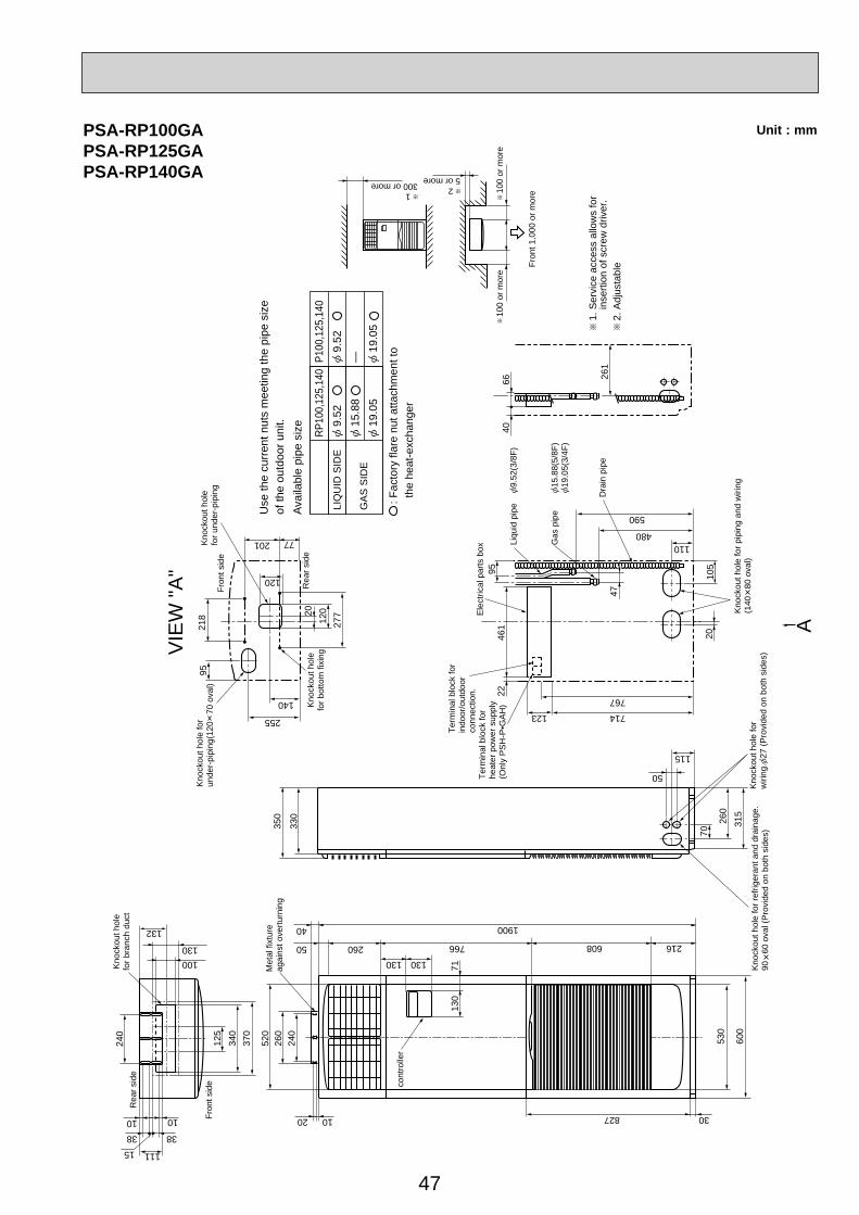
47
125
240
Fron
t sid
e
Met
al fi
xtur
eag
ains
t ove
rturn
ing
cont
rolle
r
Rea
r sid
e
Kno
ckou
t hol
efo
r bra
nch
duct
100
1038 38
50 260130 130
766
1900
608
50
115
714123
767
110480
590
216
40
827 3020 10
11115
130
132
340
370
520
260
240
130
71
530
600
350
330
70
260
315
Kno
ckou
t hol
e fo
rw
iring
.27
(Pro
vide
d on
bot
h si
des)
Kno
ckou
t hol
e fo
r ref
riger
ant a
nd d
rain
age.
90
60 o
val (
Pro
vide
d on
bot
h si
des)
Kno
ckou
t hol
e fo
r pip
ing
and
wiri
ng(1
40
80 o
val)
2010
5
Ele
ctric
al p
arts
box
Liqu
id p
ipe
9.52
(3/8
F)
1. S
ervi
ce a
cces
s al
low
s fo
r
inse
rtion
of s
crew
driv
er.
2. A
djus
tabl
e
Gas
pip
e 15
.88(
5/8F
)19
.05(
3/4F
)
Dra
in p
ipe
9546
122
47Fron
t sid
e
Rea
r sid
eK
nock
out h
ole
for b
otto
m fi
Kno
ckou
t hol
efo
r und
er-p
ipin
g
Kno
ckou
t hol
e fo
r un
der-
pipi
ng(1
20
70 o
val)
277
12020
218
255
140
77201
120
95
4066 26
1
100
or m
ore
100
or m
ore
25 or more
1300 or more
Fron
t 1,0
00 o
r mor
e
10
VIE
W "A
"
A
Term
inal
blo
ck fo
r in
door
/out
door
conn
ectio
n.Te
rmin
al b
lock
for
heat
er p
ower
sup
ply
(Onl
y P
SH
-P•G
AH
)
9.5
2RP
100,
125,
140
15.
88 1
9.05
Use
the
curr
ent n
uts
mee
ting
the
pipe
siz
eof
the
outd
oor u
nit.
Avai
labl
e pi
pe s
ize
LIQ
UID
SID
E
GA
S S
IDE
9.5
2P1
00,1
25,1
40
— 19.
05
: Fac
tory
flar
e nu
t atta
chm
ent t
o t
he h
eat-e
xcha
nger
PSA-RP100GAPSA-RP125GAPSA-RP140GA
Unit : mm

48
Unit : mm
417
6642
4556
(19) 370 28
53
175
600
175
330
2-12
36 o
val h
oles
(Fou
ndat
ion
Bolt
M10
)
Air D
ischa
rge
Rear
Air
Inta
ke
Side
Air
Inta
ke
2-U
Shap
ed n
otch
ed h
oles
(Fou
ndat
ion
Bolt
M10
)
Inst
alla
tion
Feet
30
Pipi
ng K
nock
out H
ole
Deta
ils
Exa
mpl
e of
Not
es
···
Ref
riger
ant G
AS
pip
e co
nnec
tion
(FLA
RE
)15
.88(
5/8F
)
···R
efrig
eran
t LIQ
UID
pip
e co
nnec
tion
(FLA
RE
) 9
.52(
3/8F
)1
···In
dica
tion
of S
TOP
VALV
E c
onne
ctio
n lo
catio
n.
1 2Ha
ndle
for m
oving
Sid
e A
ir In
take
Fron
t pip
ing
cove
r
Rear
pip
ing
cove
r
145
220
3014
5
81219
145
71
71
Dra
in h
ole
(5-
33)
Botto
m p
iping
hole
(Kno
ckou
t)
Air
Inta
ke
Rea
r Air
Inta
ke Hand
le fo
r mov
ing
Han
dle
for m
ovin
g
1955
232792
92
4075
7363Rig
ht p
ipin
g ho
le(K
nock
out)
Rig
ht tr
unki
ng h
ole
(Kno
ckou
t)
Pow
er s
uppl
y w
iring
hol
e(2
-27
Kno
ckou
t)
92
275573 2363
40 926545
Fron
t pip
ing
hole
(Kno
ckou
t)
Fron
t tru
nkin
g ho
le(K
nock
out)
Pow
er s
uppl
y w
iring
hol
e(2
-27
Kno
ckou
t)
92
4045 65
92
2755
237363
Rea
r pip
ing
hole
(Kno
ckou
t)
Rea
r tru
nkin
g ho
le(K
nock
out)
Pow
er s
uppl
y w
iring
hol
e (2
-27
Kno
ckou
t)
92
Ove
rOver
Less than
Pipin
g an
d wi
ring
conn
ectio
nsca
n be
mad
e fro
m 4
dire
ction
s:fro
nt, r
ight,
rear
and
belo
w.
4 PIPI
NG-W
IRING
DIRE
CTION
S3 F
OUND
ATIO
N BO
LTS
2 SER
VICE S
PACE
1 FRE
E SPA
CE (A
round
the u
nit)
The
diagr
am b
elow
show
s aba
sic e
xam
ple.
Expla
natio
n of
par
ticula
r det
ails i
sgiv
en in
the
insta
llatio
n m
anua
ls et
c.
Ove
r10
500
500
Over100
Dim
ensio
ns o
f spa
ce n
eede
dfo
r ser
vice
acce
ss a
resh
own
in th
e be
low d
iagra
m.
Serv
ice s
pace
30
Plea
se se
cure
the
unit f
irmly
with
4 fo
unda
tion
(M10
) bolt
s.(B
olts a
nd w
ashe
rs m
ust b
e pu
rcha
sed
locall
y.)
<Fou
ndati
on bo
lt heig
ht>
FOUN
DATIO
N
over
100m
mov
er 50
0mm
over
10mm
FREE
over
10mm
322
950
473943
23
*1 447*1 443
670
21
Hand
le fo
r mov
ing
Han
dle
for m
ovin
g
Ser
vice
pan
el
Earth
term
inal
Left·
··Pow
er su
pply
wirin
gRi
ght··
·Indo
or/O
utdo
or w
iring
Term
inal C
onne
ction
s
OUTDOOR UNITPUH-P71VHA PUH-P71YHAPUH-P100VHA PUH-P100YHAPU-P71VHA PU-P71YHAPU-P100VHA PU-P100YHA
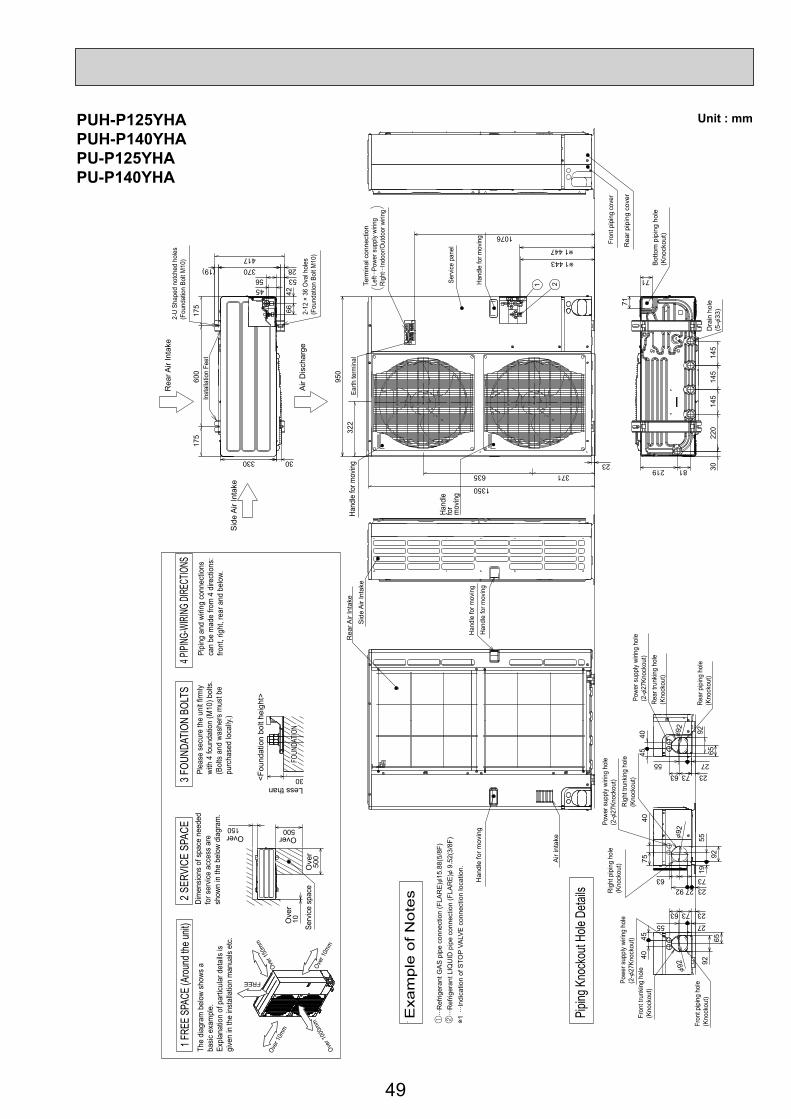
49
PUH-P125YHAPUH-P140YHAPU-P125YHAPU-P140YHA
Unit : mm
Less than
Ove
rOverOver
Ove
r
Hand
le fo
r mov
ing
Sid
e A
ir In
take
Fron
t pip
ing
cove
r
Rea
r pip
ing
cove
r
Air
inta
ke
Rea
r Air
Inta
ke
Hand
le fo
r mov
ing
Han
dle
for m
ovin
g
Term
inal
con
nect
ion
Left·
··Pow
er s
uppl
y wi
ring
Righ
t···In
door
/Out
door
wiri
ng
Earth
term
inal
Serv
ice p
anel
Hand
le fo
r mov
ing
1 2
The
diag
ram
bel
ow s
hows
aba
sic e
xam
ple.
Expl
anat
ion
of p
artic
ular
det
ails
isgi
ven
in th
e in
stal
latio
n m
anua
ls et
c.
Dim
ensio
ns o
f spa
ce n
eede
dfo
r ser
vice
acce
ss a
resh
own
in th
e be
low
diag
ram
.
<Fou
ndat
ion
bolt
heig
ht>
Plea
se s
ecur
e th
e un
it fir
mly
with
4 fo
unda
tion
(M10
) bol
ts.
(Bol
ts a
nd w
ashe
rs m
ust b
e pu
rcha
sed
loca
lly.)
Air
Dis
char
ge
Rea
r Air
Inta
ke
Sid
e A
ir In
take
···R
efrig
eran
t GA
S p
ipe
conn
ectio
n (F
LAR
E)
15.8
8(5/
8F)
···R
efrig
eran
t LIQ
UID
pip
e co
nnec
tion
(FLA
RE
) 9
.52(
3/8F
)1
···In
dica
tion
of S
TOP
VALV
E c
onne
ctio
n lo
catio
n.
Exa
mple
of
Note
s
Pipin
g Kno
ckou
t Hole
Deta
ils
1 FRE
E SP
ACE
(Arou
nd th
e unit
)2
SERV
ICE
SPAC
E3 F
OUND
ATIO
N BO
LTS
4 PIPI
NG-W
IRING
DIRE
CTIO
NSPi
ping
and
wiri
ng c
onne
ctio
nsca
n be
mad
e fro
m 4
dire
ctio
ns:
front
, rig
ht, r
ear a
nd b
elow
.
30
FOUN
DATIO
N150 500
500
10
Serv
ice s
pace
600
175
175
330
417
4266
535645
(19) 28370
2-U
Shap
ed n
otch
ed h
oles
(Fou
ndat
ion
Bolt
M10
)
2-12
× 3
6 O
val h
oles
(Fou
ndat
ion
Bolt
M10
)
Inst
alla
tion
Feet
30
4540
6592
2755237363
Rear
pip
ing
hole
(Kno
ckou
t)
Rear
trun
king
hole
(Kno
ckou
t)
Powe
r sup
ply
wirin
g ho
le(2
-27
Knoc
kout
)
92
1955
927540
7363232792Ri
ght p
ipin
g ho
le(K
nock
out)
Righ
t tru
nkin
g ho
le(K
nock
out)
Powe
r sup
ply
wirin
g ho
le(2
-27
Knoc
kout
)
92
926545
40
2755
237363
Fron
t pip
ing
hole
(Kno
ckou
t)
Fron
t tru
nkin
g ho
le(K
nock
out)
Powe
r sup
ply
wirin
g ho
le(2
-27
Knoc
kout
)
92
145
145
220
3014
5
81219
71
71
Bot
tom
pip
ing
hole
(Kno
ckou
t)
Dra
in h
ole
(5-
33)
1350
23
950
1076
1 447
1 443
371635
322
Hand
le fo
r mov
ing
Over
10mm
Over
10mm
Over
150m
m
Over
1000
mm
FREE
Hand
lefo
rm
ovin
g

50
WIRED REMOTE CONTROLLER Unit : mm
130
120
19.5

51
WIRELESS REMOTE CONTROLLER Unit : mm
159.
3
55
58
19

52
WIRING DIAGRAM4
INDOOR/OUTDOORCOMMUNICATION
CN3C(BLU)
1 1 4 1 69
1
1
3
1 3
4
5 1
4 1
1
2
3
4
5
6
7
8
9
10
11
12
13
14
15
16
17
18
19
20
CN2L
ON OFF
SWE
J42J41SW2SW1
LED3 LED2 LED1
LED2
LED1RU
SW2
SW1
CNB
3
9
5555
4 5 3 t° t° t°FS TH2 TH5 TH1
MV
BZ
MVMVMV
M M M M
W.B
TB6
R.BI.B
MT
M
1 4
2 121
21
12
12
Refer to tables 1 and 2
TRANSMISSIONWIRESDC12V
TB4YLWORN
ORNBRN
YLW
YLW
ORN
DCL
TO OUTDOORUNIT
1 3 5
3 1
DC280V
X1
M1~DP
D.U.MCNP(BLU)
FUSE
OUTDOORCN01(BLK)
RECTIFICATION
S1S2S3
7 4 1
3~
MF
MS
CN3G
U.B
AUTOMATIC FILTER ELEVATION PANEL(OPTION PART)
CN3A
3 1
AUTO GRILLE POWERCNAC(WHT)
1 3
REMOCONCN22(BLU)
I-SEE SENSORCN4Y(WHT)
I-SEESENSOR MOTOR
CN6Y(RED)
WIRELESSCN90(WHT)AUTO GRILLE
CN3G(BLK)
I-SEE SENSOR CORNER PANEL(OPTION PART)
I-SEESENSOR
GRILLE
VANE CNV(WHT)
Pair No.
FANCNMF(WHT)
INTAKECN20(RED)
FLOAT SWCN4F(WHT)
LIQUID/PIPECN44(WHT)
TB5
CN32(WHT)
CN51(WHT)
CN41(WHT)
Be sure to turn off the source power and then disconnect fan motor connector. (Failure to do so will cause trouble in Fan motor)
1313 5
<Table 1> SW1 (MODEL SELECTION)
SW1
<Table 2> SW2 (CAPACITY CODE)
SETTING
35
CAPACITYSW2
ONOFF
1 2 3 4 5100 ON
OFF
1 2 3 4 5
50 ONOFF
1 2 3 4 5125 ON
OFF
1 2 3 4 5
60 ONOFF
1 2 3 4 5140 ON
OFF
1 2 3 4 5
71 ONOFF
1 2 3 4 5
CAPACITY SETTINGSETTING
PLA-RP·BA
MODELS
ONOFF
1 2 3 4 5
ONOFF
1 2 3 4 5PLA-RP140BA2
The black square (■) indicates a switch position.
SYMBOL SYMBOLNAME NAMEI.B INDOOR CONTROLLER BOARD
FUSE (T6.3AL250V)
CONNECTOR (LOSSNAY)CONNECTOR (REMOTE SWITCH)CONNECTOR (HA TERMINAL-A)CONNECTOR (CENTRALLY CONTROL)
POWER SUPPLY (I.B)POWER SUPPLY (R.B)TRANSMISSION (INDOOR-OUTDOOR)
RELAY (DRAIN PUMP)
SWITCH (MODEL SELECTION) See table 1SWITCH (CAPACITY CODE) See table 2CONNECTOR (EMERGENCY OPERATION)
FAN MOTORVANE MOTOR
DRAIN PUMPDRAIN FLOAT SWITCH
TERMINAL BLOCK (Indoor unit Power (option))TERMINAL BLOCK (INDOOR/OUTDOOR CONNECTING LINE)TERMINAL BLOCK (REMOTE CONTROLLERTRANSMISSION LINE)
REACTOR
ROOM TEMP. THERMISTOR(0 / 15k , 25 / 5. 4k DETECT)PIPE TEMP. THERMISTOR/LIQUID(0 / 15k , 25 / 5. 4k DETECT)COND. / EVA. TEMP. THERMISTOR(0 / 15k , 25 / 5. 4k DETECT)
MF
FUSE
MV
DP
CN2L
FS
CN32 TB2CN41CN51
TB4
DCL
LED1
TB5,TB6
LED2TH1
LED3
X1
TH2SW1
TH5SW2SWE
[LEGEND]
TO OUTDOOR UNIT
135
31
CN01(BLK)
ORNYLW
BLURED
GRN/YLW
I.B1(Fig. 1)
I.B
TB2POWER SUPPLY~(1PHASE)230V 50Hz
ORNORN
YLW
BRN
TB4
INDOOR/OUTDOORCOMMUNICATIONCN3C
(BLU)
LN
S1S2S3
Please set the voltage using theremote controller.For the setting method,please refer tothe indoor unit Installation Manual.
W.B
RU
BZLED1LED2
SW1SW2
OPTION PARTPCB FOR WIRELESS REMOTE CONTROLLER
RECEIVING UNIT
BUZZERLED (OPERATION INDICATION : GREEN)LED (PREPARATION FOR HEATING : ORANGE)
EMERGENCY OPERATION (HEAT / DOWN)EMERGENCY OPERATION (COOL / UP)
Notes:1. SymboIs used in wiring diagram above are, : Connector, : Terminal (block).2. Indoor and outdoor connecting wires have poIarities, make sure to match terminal numbers (S1, S2, S3) for correct wirings.3. Since the outdoor side electric wiring may change, be sure to check the outdoor unit electric wiring diagram for servicing.4. This diagram shows the wiring of indoor and outdoor connecting wires (specification of 230V), adopting superimposed system for power and signal. 1: If indoor and outdoor units have separate power supplies, refer to Fig.1. 2: For power supply system of this unit, refer to the caution label located near this diagram.
4-1. INDOOR UNITPLA-RP35BA PLA-RP50BA PLA-RP60BA PLA-RP71BAPLA-RP100BA PLARP125BA PLA-RP140BA PLA-RP140BA2

5353
PLA-RP35AA PLA-RP50AA PLA-RP60AA PLA-RP71AA
321
321
531
MF
FAN(WHT)
RE
DW
HT
BLK
BLK
X1
X4
X1X4
C
BCR
31
DP
D.U.MCNP(BLU)
YLW
YLW
OR
N
OR
N
YLW
31 31 31 31
YLW
YLW
D.HEATERCNC(RED)
RE
DW
HT
WH
T
BR
N
POWERCNDK(RED)
POWERCND(ORN)
21POWERCN2D(WHT)
INDOOR/OUTDOORCOMMUNICATION
CN3C(BLU)
3131POWER
CND(ORN)
INDOOR/OUTDOORCOMMUNICATION
CN3C(BLU)
CN41CN51 CN2L
CN32 9
WIRELESSCN90(WHT)
BZ
5
VANECN6V(GRN)
CN2S(WHT)
CNSK(RED)
W.B
LED2
CNB
LED1
SW1 SW2 RU
21
2211
REMOCONCN22(BLU)
TB5
TRANSMISSION WIRES DC12V
TB6
R.B
BLU
BLU
321 21 21
D.SENSORCN31(WHT)
INTAKECN20(RED)
HEATERCN24(YLW)
LIQUIDCN21(WHT)
DS
TH2
21
PIPECN29(BLK)
TH3
TH1
LED3 LED2 LED1
ONOFF
SWE
Refer to tables 1and 2.
SW2 SW1
9 5 1076321 84
5
MV
5
MV
55
MV
5
MV
GRILLE
H2S1S2
TB2
TB4
POWER SUPPLY~(1PHASE)230V 50Hz
REDBLU
YLWORNORNBRN
GRN/YLW
S3
TB4
TO OUTDOOR UNIT
TO OUTDOOR UNIT
L
S1
S2S3
N
DC13.1V 1
223
1
P.B
ZNR
FUSE
I.B
I.B
YLWORN
BRNORN
YLW
ORN
1 (Fig.1)
Please set the voltage using theremote controller.For the setting method. please refer tothe indoor unit Installation Manual.
1 2 3 4 5ONOFF
MODELS
Table 1SW1Manufacture/Service
PLA-RP· AA1 2 3 4 5
ONOFF
MODELS
Table 2SW2
Manufacture/ServicePLA-RP35AAPLH-P35AAH
PLA-RP50AAPLH-P50AAH
PLA-RP60AAPLH-P60AAH
PLA-RP71AAPLH-P71AAH
1 2 3 4 5ONOFF
1 2 3 4 5ONOFF
1 2 3 4 5ONOFF
1 2 3 4 5ONOFF
PLH-P·AAH
TB2
I.B
HEATER CN24(YLW)
[PLH-P.AAH models only]
POWER SUPPLY~(1PHASE)230V 50Hz
88H FS1
26H
FS2
H1
L RED RED REDBLUGRN/YLW
WHT
WHTWHTGRY
N 21
2
65
1
88H
YLW
YLW
INDOOR POWER BOARD
[LEGEND]
P.BINDOOR CONTROLLER BOARDI.BFUSE(T6.3AL250V)FUSE
CN2L
VARISTORZNR
CONNECTOR(LOSSNAY)CN32
FAN CONTROL ELEMENTBCR
CONNECTOR(REMOTE SWITCH)CN41 CONNECTOR(HA TERMINAL-A)CN51 CONNECTOR(CENTRALLY CONTROL)
SW1 SWITCH(MODEL SELECTION) See table 1SWITCH(CAPACITY CODE) See table 2SW2
SWE CONNECTOR(EMERGENCY OPERATION)
X1 RELAY(DRAIN PUMP)X4 RELAY(FAN MOTOR)
LED1 POWER SUPPLY(I.B)LED2 POWER SUPPLY(I.B)LED3 TRANSMISSION(INDOOR-OUTDOOR)
SYMBOL NAME SYMBOL NAME SYMBOL NAME
C CAPACITOR(FAN MOTOR)
MF FAN MOTORMV VANE MOTOR
DP DRAIN PUMPDS DRAIN SENSOR
H2 DEW PREVENTION HEATER
TB4 TERMINAL BLOCK (INDOOR/OUTDOOR CONNECTING LINE)
TB2 TERMINAL BLOCK (HEATER) PLH-P.AAH models only or option for PLA-RP.AA models.
TB5, TB6 TERMINAL BLOCK(REMOTE CONTROLLER TRANSMISSION LINE)
TH1 ROOM TEMP.THERMISTOR(0 /15k ,25 /5.4k DETECT)
TH2 PIPE TEMP.THERMISTOR/LIQUID(0 /15k ,25 /5.4k DETECT)
TH5 COND./EVA. TEMP. THERMISTOR(0 /15k ,25 /5.4k DETECT)
R.B WIRED REMOTE CONTROLLER BOARD
W.B
HEATER
WIRELESS REMOTE CONTROLLER BOARDRU RECEIVING UNIT
FS1 THERMAL FUSE(72 , 16A)FS2 THERMAL FUSE(104 , 16A)H1 HEATER26H HEATER THERMAL SWITCH88H HEATER CONTACTOR
BZ BUZZERLED1 LED(RUN INDICATOR)LED2 LED(HOT ADJUST)SW1 SWITCH(HEATING ON/OFF)SW2 SWITCH(COOLING ON/OFF)
Notes:1. SymboIs used in wiring diagram above are, : Connector, : Terminal (block).2. Indoor and outdoor connecting wires have poIarities, make sure to match terminal numbers (S1, S2, S3) for correct wirings.3. Since the outdoor side electric wiring may change, be sure to check the outdoor unit electric wiring diagram for servicing.4. This diagram shows the wiring of indoor and outdoor connecting wires (specification of 230V), adopting superimposed system for power and signal. 1: If indoor and outdoor units have separate power supplies, refer to Fig.1. 2: For power supply system of this unit, refer to the caution label located near this diagram.
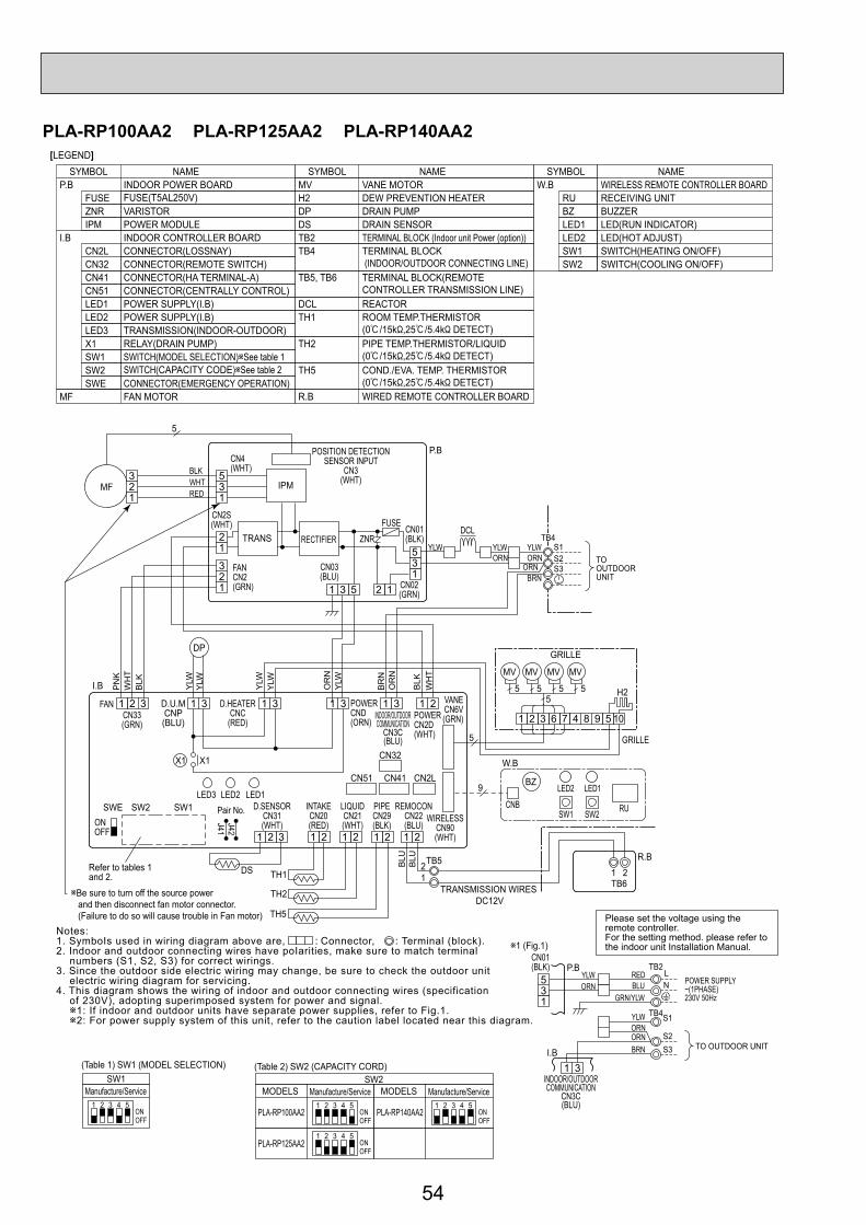
54
PLA-RP100AA2 PLA-RP125AA2 PLA-RP140AA2
Please set the voltage using theremote controller.For the setting method. please refer tothe indoor unit Installation Manual.
S1S2S3
TB4
TO OUTDOORUNIT
YLWORN
YLWYLWORN
BRNORN
111
312
2
5
123
135
53
RECTIFIERTRANS
IPM
P.B
MF123
9 5 1076321 84
5
MV
5
MV
55
MV
5
MV
GRILLE
H2
GRILLE
BLK
X1
J41J42
X1
3121 3
DP
D.U.MCNP(BLU)
YLW
YLW
OR
N
OR
N
YLW
BLK
WH
TP
NK
31 3
3
1 31
YLW
YLW
D.HEATERCNC
(RED)CN33(GRN)
CN02(GRN)
CN01(BLK)
POSITION DETECTIONSENSOR INPUT
CN3(WHT)
CN03(BLU)
CN2S(WHT)
FANCN2(GRN)
CN4(WHT)
FUSE
ZNRDCL
FAN
WH
T
BR
N
POWERCND(ORN)
21POWERCN2D(WHT)
INDOOR/OUTDOORCOMMUNICATION
CN3C(BLU)
CN41CN51 CN2L
CN32
9
WIRELESSCN90(WHT)
BZ
5
5
VANECN6V(GRN)
W.B
I.B
LED2
CNB
LED1
SW1 SW2 RU
21
2211
REMOCONCN22(BLU)
TB5
TRANSMISSION WIRES DC12V
TB6
R.B
BLU
BLU
21 21 21
D.SENSORCN31(WHT)
INTAKECN20(RED)
LIQUIDCN21(WHT)
DS
TH2
21
PIPECN29(BLK)
TH5
TH1
LED3Pair No.LED2 LED1
ONOFF
SWE
Refer to tables 1and 2.
Be sure to turn off the source power and then disconnect fan motor connector. (Failure to do so will cause trouble in Fan motor)
SW2 SW1
BLKWHTRED
31INDOOR/OUTDOORCOMMUNICATION
CN3C(BLU)
TB4YLWORNORNBRN TO OUTDOOR UNIT
S1
S2S3I.B
P.B TB2POWER SUPPLY~(1PHASE)230V 50Hz
REDBLU
GRN/YLW
LN3
1
5
CN01(BLK)
YLWORN
1 (Fig.1)
1 2 3 4 5ONOFF
(Table 1) SW1 (MODEL SELECTION)SW1
Manufacture/Service
(Table 2) SW2 (CAPACITY CORD)
1 2 3 4 5ONOFF
MODELSSW2
Manufacture/Service
PLA-RP100AA2 PLA-RP140AA2
PLA-RP125AA21 2 3 4 5
ONOFF
1 2 3 4 5ONOFF
MODELS Manufacture/Service
INDOOR POWER BOARD
[LEGEND]
P.B
INDOOR CONTROLLER BOARDI.BCN2L CONNECTOR(LOSSNAY)CN32 CONNECTOR(REMOTE SWITCH)CN41 CONNECTOR(HA TERMINAL-A)CN51 CONNECTOR(CENTRALLY CONTROL)
SW1 SWITCH(MODEL SELECTION) See table 1SWITCH(CAPACITY CODE) See table 2SW2
SWE CONNECTOR(EMERGENCY OPERATION)
X1 RELAY(DRAIN PUMP)
LED1 POWER SUPPLY(I.B)LED2 POWER SUPPLY(I.B)LED3 TRANSMISSION(INDOOR-OUTDOOR)
FUSE FUSE(T5AL250V)ZNR VARISTORIPM POWER MODULE
SYMBOL NAME SYMBOL NAME SYMBOL NAME
MF FAN MOTOR
MV VANE MOTOR
DP DRAIN PUMPDS DRAIN SENSOR
DCL REACTOR
H2 DEW PREVENTION HEATER
TB2 TERMINAL BLOCK (Indoor unit Power (option))TB4 TERMINAL BLOCK
(INDOOR/OUTDOOR CONNECTING LINE)TB5, TB6 TERMINAL BLOCK(REMOTE
CONTROLLER TRANSMISSION LINE)
TH1 ROOM TEMP.THERMISTOR(0 /15k ,25 /5.4k DETECT)
TH2 PIPE TEMP.THERMISTOR/LIQUID(0 /15k ,25 /5.4k DETECT)
TH5 COND./EVA. TEMP. THERMISTOR(0 /15k ,25 /5.4k DETECT)
R.B WIRED REMOTE CONTROLLER BOARD
W.B WIRELESS REMOTE CONTROLLER BOARDRU RECEIVING UNITBZ BUZZERLED1 LED(RUN INDICATOR)LED2 LED(HOT ADJUST)SW1 SWITCH(HEATING ON/OFF)SW2 SWITCH(COOLING ON/OFF)
Notes:1. SymboIs used in wiring diagram above are, : Connector, : Terminal (block).2. Indoor and outdoor connecting wires have poIarities, make sure to match terminal numbers (S1, S2, S3) for correct wirings.3. Since the outdoor side electric wiring may change, be sure to check the outdoor unit electric wiring diagram for servicing.4. This diagram shows the wiring of indoor and outdoor connecting wires (specification of 230V), adopting superimposed system for power and signal. 1: If indoor and outdoor units have separate power supplies, refer to Fig.1. 2: For power supply system of this unit, refer to the caution label located near this diagram.

55
6 5 4 3 2
5
1
MF
FAN(WHT)
LED1 CN90 CN32
I.B
LED2
LED3 CN41
2 1REMOTE
CONTROLLERCN22(BLU)
BLU
BLU
TB5
TB4S1S2S3
TB6
R.B
TRANSMISSION WIRES DC12V21 1 2
21 TH1
321 DS
D.SENSORCN31(WHT)
INTAKECN20(RED)
BLK
BLK
BLKBLK
21 TH2
LIQUIDCN21(WHT)
BLKBLK
21 TH5
PIPECN29(BLK)
BLKBLK
VANECN6V(WHT)
654321
12345
MV
BRNREDORNYLWGRN
CN2L
See Fig. 1
SW1SWE
ON
OFF
SW2
J24J23J22J21
J15J14J13J12J11
31
135
DP X1X1
D.U.MCNP
(YLW)
POWERCN03(RED)
FUSE ZNR
T
BRNORNYLW
BLUBLU
TO OUTDOOR UNIT
MODELS
SW1
<Fig.1>
PMH-P25/35/50BA
Manufacture
J11 J12 J13 J14 J15
Service board
SW2
PMH-P25BAJ21 J22 J23 J24
ONOFF
1 2 3 4
1 2 3 4 5ONOFF
PMH-P35BAJ21 J22 J23 J24
ONOFF
1 2 3 4
PMH-P50BAJ21 J22 J23 J24
ONOFF
1 2 3 4
Please set the voltage using the remote controller.For the setting method, please refer to the indoorunit Installation Manual.
SYMBOL[LEGEND]
I.B INDOOR CONTROLLER BOARDCN2L CONNECTOR(LOSSNAY)CN32 CONNECTOR(REMOTE SWITCH)CN41 CONNECTOR(HA TERMINAL-A)FUSE FUSE(6.3A , 250V)LED1 POWER SUPPLY(I.B)LED2 POWER SUPPLY(R.B)LED3 TRANSMISSION(INDOOR-OUTDOOR)SW1 JUMPER WIRE(MODEL SELECTION)SW2 JUMPER WIRE(CAPACITY CODE)SWE SWITCH(EMERGENCY OPERATION)T TRANSFORMERX1 RELAY(DRAIN PUMP)ZNR VARISTOR
NAME SYMBOL
R.B WIRED REMOTE CONTROLLER BOARD
DP DRAIN PUMPDS DRAIN SENSORMF FAN MOTORMVTB4
VANE MOTORTERMINAL BLOCK(INDOOR / OUTDOOR CONNECTING LINE)
TB5,TB6 TERMINAL BLOCK(REMOTE CONTROL TRANSMISSION LINE)
TH1 ROOM TEMP. THERMISTOR(0 /15k 25 /5.4k DETECT)
TH2 PIPE TEMP. THERMISTOR / LIQUID(0 /15k 25 /5.4k DETECT)
TH5 COND, / EVA. TEMP, THERMISTOR (0 /15k 25 /5.4k DETECT)
NAME
Notes:1. SymboIs used in wiring diagram above are, : Connector, : Terminal (block).2. Indoor and outdoor connecting wires have poIarities, make sure to match terminal numbers (S1, S2, S3) for correct wirings.3. Since the outdoor side electric wiring may change, be sure to check the outdoor unit electric wiring diagram for servicing.4. This diagram shows the wiring of indoor and outdoor connecting wires (specification of 230V), adopting superimposed system for power and signal.
PMH-P25BA PMH-P35BA PMH-P50BA

56
PEAD-RP35JA(L) PEAD-RP50JA(L) PEAD-RP60JA(L) PEAD-RP71JA(L)PEAD-RP100JA(L) PEAD-RP125JA(L) PEAD-RP140JA(L)
12
1 3
5
1
124 3
21542 3
32
14
2121
4
1 3
MM
45
67
12
11
23
35
1
321 3 4
41 2
21
INSIDE
SECT
ION OF
CONT
ROL B
OX
Conn
ecto
r (0-
10V
Anal
og in
put)
Conn
ecto
r (IT
term
inal
)Co
nnec
tor (
Wire
less
)
Indo
or c
ontro
ller b
oard
NO
TE: 1
. Sin
ce th
e ou
tdoo
r sid
e el
ectri
c w
iring
may
cha
nge
be s
ure
toch
eck
the
outd
oor u
nit e
lect
ric w
iring
for s
ervi
cing
.2.
Indo
or a
nd o
utdo
or c
onne
ctin
g w
ires
are
mad
e w
ith p
olar
ities
,m
ake
wiri
ng m
atch
ing
term
inal
num
bers
(S1,
S2,
S3)
.3.
Sym
bols
use
d in
wiri
ng d
iagr
am a
bove
are
,te
rmin
al b
lock
,co
nnec
tor.
Varis
tor
Aux.
rela
y
Fuse
AC25
0V 6
.3A
Conn
ecto
r (Ce
ntra
lly c
ontro
l)Co
nnec
tor (
HA te
rmin
al-A
)
LED(
Rem
ote
cont
rolle
r sup
ply)
Indo
or c
ontro
ller b
oard
Conn
ecto
r (Re
mot
e sw
itch)
LED(
Tran
smiss
ion
indo
or-o
utdo
or)
Arre
ster
Inta
ke a
ir te
mp.
Ther
mist
orPi
pe te
mp.
Ther
mist
or/liq
uid
Cond
./eva
.tem
p.Th
erm
istor
AC re
acto
r (Po
wer f
acto
r im
prov
emen
t)Co
nnec
tor (
Loss
nay)
LED(
Powe
r sup
ply)
Term
inal
blo
ck(R
emot
e co
ntro
ller t
rans
miss
ion
line)
Term
inal
blo
ckFl
oat s
witc
h
(Indo
or/o
utdo
or c
onne
ctin
g lin
e)
Powe
r sup
ply
boar
d
Aux.
rela
y
Switc
h (fo
r mod
e se
lect
ion)
Switc
h (fo
r cap
acity
cod
e)Co
nnec
tor (
emer
genc
y op
erat
ion)
Drai
n pu
mp
Fan
mot
or
(Blu
e)
(Blu
e)(R
ed)
(Blu
e)
(Red
)(B
lue)
TO O
UTDO
ORUN
IT
<A>
(Blu
e)
SW2
SW1
t°t°
t°
U
DC28
0~34
0VRe
ctifie
r circ
uit
U
(Red
)
(Red
)
(Bla
ck)
ON
OFF
(IN C
ASE
OF
CONN
ECT
THE
REPL
ACEM
ENT
WIR
ING
)
POW
ER S
UPPL
Y~(
1PHA
SE)
220~
240V
50H
z
A
TO M
A REM
OTE
CONT
ROLLE
R
TO OU
TDOO
R UNIT
CN2A
CN2L
CN32
CN41
CN51
CN90
CN10
5LE
D1LE
D2LE
D3
I.B.
I.B.
P.B.
SW1
SW2
SWE
F01
ZNR0
1, 02
DSA
X01
X10
TH1
TH2
TH5
ACL
FS TB4
TB15
SYM
BOL
NAM
ESY
MBO
LNA
ME
SYM
BOL
NAM
ESY
MBO
L EX
PLAN
ATIO
N
FSTH
1TH
5TH
21~
I.B.
P.B.
CN10
5
CN2A
CN22
LED1
CNXA
2CN
XC2
CNXB
2
CN2L
CN4F
CN20
CN44
LED3
CN90
CN3C
CN32
CN41
CN51
SWE
LED2
CND
F01
DSA
ZNR0
2ZN
R01
CNP
X01
X10
CNXB
1CN
XC1
CNXA
1CN
MF
ACL
ACL
1 21 2 1 2
L N S1 S2 S3TO
CND
TO C
N3C
TB15
1 2 S1 S2 S3
TB4
*1*1
*1. D
rain
pum
p an
d flo
at s
witc
h: o
nly
for P
EAD-
JA m
odel

57
PEAD-RP35EA2 PEAD-RP50EA PEAD-RP60EA PEAD-RP71EAPEAD-RP100EA2 PEAD-RP125EA PEAD-RP140EA
< A>
NL
S1S2
1 221
1 2
S3TO CND
TO OUTDOORUNIT
TO CN3C
ONOFF
1 2 3 4 5
ONOFF
1 2 3 4 5
ONOFF
1 2 3 4 5
ONOFF
1 2 3 4 5
ONOFF
1 2 3 4 5
ONOFF
1 2 3 4 5
ONOFF
1 2 3 4 5
54321
OFFON
50EA
60EA
71EA
35EA(2)
100EA(2)
125EA
140EA
Capacity cordswitch
Model selectionswitch
SW2SW1MODELS
POWER SUPPLY~(1PHASE)230V 50Hz
(IN CASE OF CONNECT THE REPLACEMENT WIRING)
TO OUTDOOR UNIT
TO MA-REMOTECONTROLLERDC8.7-13V
I.B.
X6X4
X5
X1ZNR
FUSE
P.B.
CN31
1 3
DS
INSIDE SECTION OF CONTROL BOX
BLU
BLU
BLU B
LU
TB5 (RED)643 521
C
MF
X6X5X4X1
(RED)CNDK
(BLU)CNP
(WHT)FAN
1
YLW
ORN
(ORN)
3 1CND
21
(RED)
LED1LED2LED3
CN2L
OFFON
SWE
SW2 SW1
(RED) (WHT)
PNK
PNK
BLK
BLK
WHT
BLK
BLK
WHT
WHT
WHT
12 3 1CN2S CNSK(WHT) (RED)
YLWORNBRN
BRN
ORN
(BLU)
WHTBLK CN2D
(WHT)
(BLU) (RED) (WHT) (BLK) (WHT) (WHT) (WHT) (YLW) (WHT) (WHT)
A
DP
643 52121
TB4S3
S1S2
2
133 1
643 521
MFC
1 2
CN24
3211 2 31 2 1 21 2
TH5TH2TH1
12
CN3C
3 1
137 5
CN22 CN20 CN21 CN29 CN31 CN90 CN41 CN51 CN32
21 1 2 3 4 5 6 7 8 9 4321 4 5321
<PEAD-RP71•100•125•140EA, 100EA2> External static pressure 130Pa
<PEAD-RP71•100•125•140EA, 100EA2> External static pressure 70Pa
<PEAD-RP35•50•60EA, 35EA2> External static pressure 70Pa
Optional parts
Optional parts
<PEAD-RP35•50•60EA, 35EA2> External static pressure 30Pa
(OPTIONAL PARTS)DRAIN PUMP
RELAY(DRAIN PUMP)X1
CONNECTOR(WIRELESS) DPDS
TRANSMISSION(INDOOR•OUTDOOR)LED3SWITCH(MODEL SELECTION)SW1
POWER SUPPLY(REMOTE CONTROLLER)LED2LED1 POWER SUPPLY(I.B.)CN90CN51 CONNECTOR(CENTRALLY CONTROL)
CN24 CONNECTOR(HEATER)
VARISTORFUSE(T6.3AL250V)
ZNRFUSE
INDOOR POWER BOARDP.B.COND./EVA. TEMP. THERMISTOR(0 /15kΩ,25 /5.4kΩ DETECT)
PIPE TEMP. THERMISTOR/LIQUID(0 /15kΩ,25 /5.4kΩ DETECT)
INTAKE AIR TEMP. THERMISTOR(0 /15kΩ,25 /5.4kΩ DETECT)
TERMINAL BLOCK(REMOTE CONTROLLER)
FAN MOTORCAPACITOR(FAN MOTOR)DRAIN SENSORDRAIN PUMP
TH5
TH2
TH1TB5
(INDOOR/OUTDOOR CONNECTING LINE)TERMINAL BLOCKTB4
MFC
NAMENAME SYMBOLSYMBOLNAME
RELAY(FAN MOTOR)RELAY(FAN MOTOR)
SWITCH(CAPACITY CODE)
CONNECTOR(HA TERMINAL-A)CONNECTOR(REMOTE SWITCH)
INDOOR CONTROLLER BOARD
RELAY(FAN MOTOR)
SWITCH(EMERGENCY OPERATION)
CONNECTOR(LOSSNAY)
X6X5X4
SWESW2
CN41CN32
CN2L
I.B.SYMBOL
Notes:1. SymboIs used in wiring diagram above are, : Connector, : Terminal (block).2. Indoor and outdoor connecting wires have poIarities, make sure to match terminal numbers (S1, S2, S3) for correct wirings.3. Since the outdoor side electric wiring may change, be sure to check the outdoor unit electric wiring diagram for servicing.4. This diagram shows the wiring of indoor and outdoor connecting wires (specification of 230V), adopting superimposed system for power and signal. 1: If indoor and outdoor units have separate power supplies, refer to A. 2: For power supply system of this unit, refer to the caution label located near this diagram.

58
PEAD-RP60GA PEAD-RP71GA PEAD-RP100GA
Capacity cordswitch
Model selectionswitch
SW2SW1
ONOFF
1 2 3 4 5
ONOFF
1 2 3 4 5
ONOFF
1 2 3 4 5
54321
OFFON
100GA
71GA
60GA
MODELS< A>
NL
S1S2
1 221
1 2
S3TO CND
TO OUTDOORUNIT
TO CN3C
POWER SUPPLY~(1PHASE)230V 50Hz
(IN CASE OF CONNECT THE REPLACEMENT WIRING)
TO MA-REMOTECONTROLLERDC8.7-13V
TO OUTDOOR UNIT
X6
X5
X4X1ZNR
FUSE
P.B.
I.B.
X1
YLW
ORN
X6X5X4
21
(RED)
(WHT)(WHT)(YLW)(WHT)(WHT)(WHT)
BLU
BLU
BLU
BLU
(BLK)(WHT)(RED)(BLU)
BLK
WHT
BLKWHT
(WHT)
(BLU)
BRN
BRN
ORN
ORNYLW
(BLU)(RED)(ORN)
(RED)(WHT)
BLK
WHT
BLK
WHT
(WHT)
(WHT)
ORG
BLK
BLU
BLK
YLW
YLW
GRY
A
*
(FACTORY SHIPMENT)
240V230V220V20Pa
60Pa
75Pa
10Pa
50Pa
70Pa50Pa
35Pa
5Pa
RED
WHT
BLUCONNECTOR COLOR
21
TB5
TB4S3
S1S2
2 1
CNP133 13 1
13CNSK
2 1CN2S 643 521
MFC
1 2
CN24
3211 2 31 2 1 21 2
TH5TH2TH1
LED1LED2LED3
12 CN2D
CN3C
3 1CND CNDK
137FAN
5
OFFON
SWE
SW2
SW1
CN2L
CN22 CN20 CN21 CN29 CN31 CN90 CN41 CN51 CN32
21 1 2 3 4 5 6 7 8 9 4321 54321
INSIDE SECTION OF CONTROL BOX
*External static pressure
RELAY(DRAIN PUMP)X1
CONNECTOR(WIRELESS)
TRANSMISSION(INDOOR•OUTDOOR)LED3POWER SUPPLY(REMOTE CONTROLLER)LED2
LED1 POWER SUPPLY(I.B.)CN90CN51 CONNECTOR(CENTRALLY CONTROL)
CN24 CONNECTOR(HEATER)
VARISTORFUSE(T6.3AL250V)
ZNRFUSE
INDOOR POWER BOARDP.B.
COND./EVA. TEMP. THERMISTOR(0 /15kΩ,25 /5.4kΩ DETECT)
PIPE TEMP. THERMISTOR/LIQUID(0 /15kΩ,25 /5.4kΩ DETECT)
INTAKE AIR TEMP.THERMISTOR(0 /15kΩ,25 /5.4kΩ DETECT)
TERMINAL BLOCK(INDOOR/OUTDOOR CONNECTING LINE)
TERMINAL BLOCK(REMOTE CONTROLLER)
FAN MOTORCAPACITOR(FAN MOTOR)
TH5
TH2
TH1
TB4
TB5
MFC
NAMENAME SYMBOLSYMBOLNAME
RELAY(FAN MOTOR)RELAY(FAN MOTOR)
SWITCH(CAPACITY CODE)
CONNECTOR(HA TERMINAL-A)CONNECTOR(REMOTE SWITCH)
INDOOR CONTROLLER BOARD
RELAY(FAN MOTOR)
SWITCH(EMERGENCY OPERATION)
SWITCH(MODEL SELECTION)
CONNECTOR(LOSSNAY)
X6X5X4
SWESW2SW1
CN41CN32
CN2L
I.B.SYMBOL
Notes:1. SymboIs used in wiring diagram above are, : Connector, : Terminal (block).2. Indoor and outdoor connecting wires have poIarities, make sure to match terminal numbers (S1, S2, S3) for correct wirings.3. Since the outdoor side electric wiring may change, be sure to check the outdoor unit electric wiring diagram for servicing.4. This diagram shows the wiring of indoor and outdoor connecting wires (specification of 230V), adopting superimposed system for power and signal. 1: If indoor and outdoor units have separate power supplies, refer to A. 2: For power supply system of this unit, refer to the caution label located near this diagram.
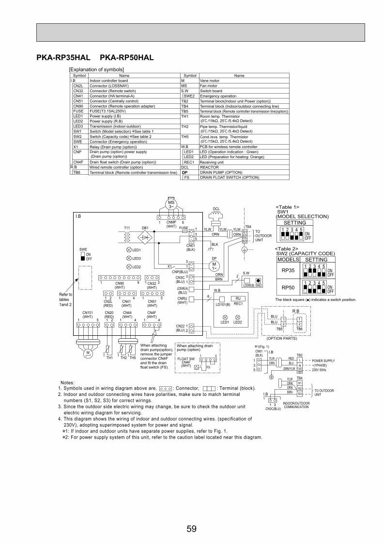
59
PKA-RP35HAL PKA-RP50HAL
Terminal block (Remote controller transmission line)R.B
Symbol Name Symbol NameI.B Indoor controller board
FUSE FUSE(T3.15AL250V)
CN2L Connector (LOSSNAY)
CN90 Connector (Remote operation adapter)
Connector (Emergency operation)
CNP Drain pump (option) power supply (Drain pump (option))
CN4F Drain float switch (Drain pump (option))DCL REACTOR
CN32 Connector (Remote switch)CN41 Connector (HA terminal-A)CN51 Connector (Centrally control)
LED1 Power supply (I.B)LED2 Power supply (R.B)LED3 Transmission (Indoor-outdoor)
X1 Relay (Drain pump (option))
SW1 Switch (Model selection) See table 1SW2SWE
Switch (Capacity code) See table 2
[Explanation of symbols]
MS Fan motor
W.B PCB for wireless remote controller
Switch boardSWE2 Emergency operation
M Vane motor
LED1 LED (Operation indication : Green)
REC1 Receiving unitLED2 LED (Preparation for heating: Orange)
TB2 Terminal block(Indoor unit Power (option))TB4 Terminal block (Indoor/outdoor connecting line)TB5 Terminal block (Remote controller transmission line(option))TH1 Room temp. Thermistor
Pipe temp. Thermistor/liquid
Cond./eva. temp. Thermistor
(0 /15kΩ, 25 /5.4kΩ Detect)
(0 /15kΩ, 25 /5.4kΩ Detect)
(0 /15kΩ, 25 /5.4kΩ Detect)
TH2
TH5
S.W
Wired remote controller (option)TB6 DPDP DRAIN PUMP (OPTION)
DRAIN FLOAT SWITCH (OPTION)FS
Notes:1. SymboIs used in wiring diagram above are, : Connector, : Terminal (block).2. Indoor and outdoor connecting wires have poIarities, make sure to match terminal numbers (S1, S2, S3) for correct wirings.3. Since the outdoor side electric wiring may change, be sure to check the outdoor unit electric wiring diagram for servicing.4. This diagram shows the wiring of indoor and outdoor connecting wires. (specification of 230V), adopting superimposed system for power and signal.
1: If indoor and outdoor units have separate power supplies, refer to Fig. 1.2: For power supply system of this unit, refer to the caution label located near this diagram.
TO OUTDOOR UNIT
531
31
CN01(BLK)
ORNYLW
BLURED
GRN/YLW
I.B1(Fig. 1)
I.B
POWER SUPPLY~(1PHASE)230V 50Hz
L
N
ORNORN
YLW
BRN
TB4
TB2
S1
S2
S3
INDOOR/OUTDOORCOMMUNICATIONCN3C(BLU)
Refer to tables1and 2
CN90(WHT)
CN2L(RED)
CN151(WHT)
CN20(RED)
CN44(WHT)
CN4F(WHT)
CN22(BLU)
CN41(WHT)
CN51(WHT)
CN32(WHT)
CNMF(WHT)
S.W
W.B
SWE
R.B
CNP(BLU)CN3C(BLU)
CNRU(WHT)
LDSWE(A)(BLU)
LDSWE(B)
LD101(B) REC1
LED1 LED2
SWE2
CN01(BLK)
T11 DB1
X1
FUSE
I.B1
1
1 1 1 5 64
1 112
1 4 1 425
TH1 TH2 TH5
2
1 31 9
3
3
3 2
21
21
1
1
5
6
Mt○ t○ t○
MS3~
M1~
TB4
TB5
S1S2S3
RU
BLUBLU
ORN
ORN
DP
ORN
BRN
LED1
LED3
LED2
(OPTION PARTS)
TB6
ONOFF
TOOUTDOORUNIT
YLW YLWYLW
DCL
BLK
<Table 1> SW1(MODEL SELECTION)
SETTING
SETTING
ONOFF
1 2 3 4 5
<Table 2> SW2 (CAPACITY CODE)MODELS
RP35 ONOFF
1 2 3 4 5
ONOFF
1 2 3 4 5RP50
FLOAT SWCN4F(WHT)
When attaching drain pump(option), remove the jumper connector CN4F and fit the drain float switch (FS).
When attaching drain pump (option)
FS
1 4
The black square (■) indicates a switch position.

60
PKA-RP60KAL PKA-RP71KAL PKA-RP100KAL
LOBMYSLOBMYS EMANEMANI.B
R.B
Indoor controller board
FUSE (T3.15AL250V)
Connector (LOSSNAY)Connector (Remote switch)Connector (HA terminal-A)Connector (Centrally control)
Power supply (I.B)Power supply (R.B)Transmission (Indoor-outdoor)
Relay (Drain pump(option))
Switch (Model selection) See table 1Switch (Capacity code) See table 2Connector (Emergency operation)
Vane motorFan motor
DRAIN PUMP (OPTION)DRAIN FLOAT SWITCH (OPTION)
Terminal block (Indoor unit Power (option))Terminal block (Indoor/outdoor connecting line)Terminal block (Remote controller transmission line)
REACTOR
Room temp. Thermistor(0 / 15k , 25 / 5. 4k Detect)Pipe temp. Thermistor/liquid(0 / 15k , 25 / 5. 4k Detect)Cond. / eva. temp. Thermistor(0 / 15k , 25 / 5. 4k Detect)
M
FUSE
MSSwitch boardS.WEmergency operationSWE2
Drain pump (option) power supply(Drain pump(option))
CNP
DP
CN2L
FS
CN32
TB2CN41CN51
Connector (Remote operation adapter)CN90 TB4
DCL
LED1TB5
LED2TH1
LED3
X1
Drain float switch (Drain pump (option))CN4FWired remote controller (option)Terminal block (Remote controller transmission line)TB6
TH2SW1
TH5SW2SWE
[LEGEND]
TO OUTDOORUNIT
531
31
CN01(BLK)
ORNYLW
BLURED
GRN/YLW
I.B1(Fig. 1)
I.B
TB2POWER SUPPLY~(1PHASE)230V 50Hz
ORNORN
YLW
BRN
TB4
INDOOR/OUTDOORCOMMUNICATIONCN3C (BLU)
LN
S1S2S3
W.B
REC1
LED1LED2
PCB for wireless remote controller
Receiving unit
LED (Operation indication : Green)LED (Preparation for heating : Orange)
1. SymboIs used in wiring diagram above are, :Connector, : Terminal (block).2. Indoor and outdoor connecting wires have poIarities, make sure to match terminal numbers (S1, S2, S3) for correct wirings.3. Since the outdoor side electric wiring may change, be sure to check the outdoor unit electric wiring diagram for servicing.4. This diagram shows the wiring of indoor and outdoor connecting wires.(specification of 230V), adopting superimposed system for power and signal.
1 If indoor and outdoor units have separate power supplies, refer to Fig 1.2 For power supply system of this unit, refer to the caution label located near this diagram.
Notes:
MF
The black square (■) indicates a switch position.

61
PKA-RP35GAL PKA-RP50GAL
P.B INDOOR POWER BOARDSYMBOL NAME
I.B INDOOR CONTROLLER BOARDFUSE FUSE (T6.3AL250V)ZNR VARISTORCN2L CONNECTOR <LOSSNAY>CN32 CONNECTOR <REMOTE SWITCH>CN41 CONNECTOR <HA TERMINAL-A>CN51 CONNECTOR <CENTRALLY CONTROL>SW1 SWITCH <MODEL SELECTION> See Table 1.SW2 SWITCH <CAPACITY CODE> See Table 2.SWE SWITCH <EMERGENCY OPERATION>X4 RELAY <FAN MOTOR>BCR
POWER SUPPLY <R.B>LED1 POWER SUPPLY <I.B>LED2
TRANSMISSION <INDOOR-OUTDOOR>LED3
FAN CONTROL ELEMENT
C CAPACITOR <FAN MOTOR> FAN MOTORVANE MOTOR
MFMV
SYMBOL NAME
TB4 TERMINAL BLOCK <INDOOR/ OUTDOOR
TB2 TERMINAL BLOCK (HEATER) PKH-P.GALH models only or option for PKA-RP.GAL models.
CONNECTING LINE>TERMINAL BLOCK <REMOTE CONTROLLERTRANSMISSION LINE> <OPTION>ROOM TEMP.THERMISTOR <0 / 15k , 25 / 5.4k DETECT>PIPE TEMP.THERMISTOR/ LIQUID <0 / 15k , 25 / 5.4k DETECT>COND./ EVA.TEMP.THERMISTOR <0 / 15k , 25 / 5.4k DETECT>
TB5,TB6
TH5
TH1
TH2
W.B WIRELESS REMOTE CONTROLLER BOARDRECEIVING UNIT BUZZERLED <RUN INDICATOR>LED <HOT ADJUST>SWITCH (HEATING ON/ OFF>SWITCH (COOLING ON/ OFF>WIRED REMOTE CONTROLLER BOARDR.B
HEATER
RUBZLED1LED2SW1SW2
NAMESYMBOL
HEATERH1THERMAL FUSE <84 10A>FS2THERMAL FUSE <104 10A>FS1
HEATER THERMAL SWITCH26HHEATER CONTACTOR88H
INTAKECN20(RED)
LIQUIDCN21(WHT)
PIPECN29(BLK)
1 2 1 2 1 2
1 31 31 3 1 2
TH5TH1 TH2
REMOCONCN22(BLU)1 2
21
TB5
R.B
TB621
TRANSMISSION WIRES DC12V
SWEONOFF
SW2 SW1
LED3 LED2 LED1
ZNR
FUSE
X4
CN41 CN2L
CN51 CN32
WIRELESSCN90(WHT)
VANECN6V(GRN) MV
6
W.B
BZ CNB
RECEIVERRU
LED1 LED2 SW2 SW1
9
FAN(WHT)
1 3 5
1
12
12
32 3
BLK
WHT
WHT
RED
RED
C
MF
X4BCR
TO OUTDOORUNIT
TB4S1S2S3
YLW
ORNORN
BRNYLW
ORN
BLK
WHT
P.B
I.BPOWERCNDK(RED)
CNDK(RED)
DC13.1V
CN2S(WHT)
POWERCND
(ORN) POWERCN2D(WHT)
INDOOR/OUTDOORCOMMUNICATIONCN3C(BLU)
3131POWER
CND(ORN)
INDOOR/OUTDOORCOMMUNICATION
CN3C(BLU)
TB2
TB4
POWERSUPPLY~(1PHASE)230V 50Hz
REDBLU
YLWORNORNBRN
TO OUTDOORUNIT
L
S1
S2S3
N
I.B YLW
ORN
1 (Fig.1)
Refer to tables 1and 2 for service PCB.
GRN/YLW
TB2I.B
HEATER CN24(YLW)
POWER SUPPLY~(1PHASE)230V 50Hz
88HFS226H
H1 LREDRED 5 3REDBLU
GRN/YLW
WHTRED6 1 REDGRY
N21
2
65
1FS1
88H
YLW
YLW
SW1Service board
SW2Service board Service board
1 2 3 4 5ONOFF
1 2 3 4 5ONOFF
MODELSPKA-RP35GALPKH-P35GALH
1 2 3 4 5ONOFF
MODELSPKA-RP50GALPKH-P50GALH
Please set the voltage using theremote controller.For the setting method,please refer tothe indoor unit Installation Manual.
PKH-P35,50GALH models only
Notes:1. SymboIs used in wiring diagram above are, : Connector, : Terminal (block).2. Indoor and outdoor connecting wires have poIarities, make sure to match terminal numbers (S1, S2, S3) for correct wirings.3. Since the outdoor side electric wiring may change, be sure to check the outdoor unit electric wiring diagram for servicing.4. This diagram shows the wiring of indoor and outdoor connecting wires (specification of 230V), adopting superimposed system for power and signal. 1: If indoor and outdoor units have separate power supplies, refer to Fig.1. 2: For power supply system of this unit, refer to the caution label located near this diagram.

62
PKA-RP50FAL2 PKA-RP60FAL PKA-RP71FAL PKA-RP100FAL
INTAKECN20(RED)
LIQUIDCN21(WHT)
PIPECN29(BLK)
1 2 1 2 1 2
1 31 31 3 1 2
TH5TH1 TH2
REMOCONCN22(BLU)1 2
21
TB5
R.B
TB621
TRANSMISSION WIRES DC12V
SWEONOFF
SW2 SW1
LED3 LED2 LED1
ZNR
FUSE
X4
CN41 CN2L
CN51 CN32
WIRELESSCN90(WHT)
VANECN6V(GRN) MV
6
W.B
BZ CNB
RECEIVERRU
LED1 LED2 SW2 SW1
9
FAN(WHT)
1 3 5
1
12
12
32 3
BLK
WHT
WHT
RED
RED
C
MF
X4BCR
TO OUTDOORUNIT
TB4S1S2S3
YLW
ORNORN
BRNYLW
ORN
BLK
WHT
P.B
I.B
Please set the voltageusing the remote controller.For the setting method,please refer to the indoorunit Installation Manual
SW1Table 1
Service boardSW2
Table 2
Service board Service board Service board
POWERCNDK(RED)
CNDK(RED)
DC13.1V
CN2S(WHT)
POWERCND
(ORN) POWERCN2D(WHT)
INDOOR/OUTDOORCOMMUNICATIONCN3C(BLU)
3131POWER
CND(ORN)
INDOOR/OUTDOORCOMMUNICATION
CN3C(BLU)
TB2
TB4
POWERSUPPLY (1PHASE)230V 50Hz
REDBLU
YLWORNORNBRN
TO OUTDOORUNIT
L
S1
S2S3
N
I.B YLW
ORN
1 (Fig.1)
Refer to tables 1and 2 for service PCB.
1 2 3 4 5ONOFF
1 2 3 4 5ONOFF
MODELSPKA-RP50FAL2PKA-RP60FALPKH-P60FALH
1 2 3 4 5ONOFF
MODELSPKA-RP71FALPKH-P71FALH
1 2 3 4 5ONOFF
MODELSPKA-RP100FALPKH-P100FALH
TB2I.B
HEATER CN24(YLW)
PKH-P60 P100FALH models only
POWER SUPPLY (1PHASE)230V 50Hz
88HFS226H
H1
LREDRED 5 3REDBLU
GRN/YLW
WHTRED6 1 REDGRY
N21
2
65
1FS1
88H
YLW
YLW
GRN/YLW
P.B INDOOR POWER BOARDSYMBOL NAME
I.B INDOOR CONTROLLER BOARDFUSE FUSE(T6.3AL250V)ZNR VARISTORCN2L CONNECTOR(LOSSNAY)CN32 CONNECTOR(REMOTE SWITCH)CN41 CONNECTOR(HA TERMINAL-A)CN51 CONNECTOR(CENTRALLY CONTROL)SW1 SWITCH (MODEL SELECTION) See Table 1.SW2 SWITCH (CAPACITY CODE) See Table 2.SWE SWITCH(EMERGENCY OPERATION)X4 RELAY(FAN MOTOR)BCR
POWER SUPPLY(R.B)LED1 POWER SUPPLY(I.B)LED2
TRANSMISSION(INDOOR-OUTDOOR)LED3
FAN CONTROL ELEMENT
C CAPACITOR(FAN MOTOR) FAN MOTORVANE MOTOR
MFMV
SYMBOL NAME
TB4 TERMINAL BLOCK(INDOOR/OUTDOOR
TB2 TERMINAL BLOCK (HEATER) PKH-P·FALH models only or option for PKA-RP·FAL models.
CONNECTING LINE)TERMINAL BLOCK(REMOTE CONTROLLERTRANSMISSION LINE )(OPTION)ROOM TEMP.THERMISTOR(0°C/15kΩ, 25°C/5.4kΩ DETECT)PIPE TEMP.THERMISTOR/LIQUID(0°C/15kΩ, 25°C/5.4kΩ DETECT)COND./EVA.TEMP.THERMISTOR(0°C/15kΩ, 25°C/5.4kΩ DETECT)
TB5
TH5
TH1
TH2
W.B WIRELESS REMOTE CONTROLLER BOARDRECEIVING UNIT BUZZERLED(RUN INDICATOR )LED(HOT ADJUST)SWITCH(HEATING ON/OFF)SWITCH(COOLING ON/OFF)WIREDREMOTE CONTROLLER BOARD(OPTION)TERMINAL BLOCK(REMOTE CONTROLLER
THERMAL FUSE(117°C 10A:60,71FALH/117°C 16A:100FALH)
TRANSMISSION LINE)
R.B
HEATER
RUBZLED1LED2SW1SW2
NAMESYMBOL
HEATERH1HEATER THERMAL SWITCH26HHEATER CONTACTOR88H
TB6
FS1,2
Notes:1. SymboIs used in wiring diagram above are, : Connector, : Terminal (block).2. Indoor and outdoor connecting wires have poIarities, make sure to match terminal numbers (S1, S2, S3) for correct wirings.3. Since the outdoor side electric wiring may change, be sure to check the outdoor unit electric wiring diagram for servicing.4. This diagram shows the wiring of indoor and outdoor connecting wires (specification of 230V), adopting superimposed system for power and signal. 1: If indoor and outdoor units have separate power supplies, refer to Fig.1. 2: For power supply system of this unit, refer to the caution label located near this diagram.

63
PCA-RP50KA PCA-RP50KA PCA-RP60KA PCA-RP71KAPCA-RP100KA PCA-RP125KA PCA-RP140KA
DCL
TO OUTDOOR UNIT
135
31
CN01(BLK)
ORNYLW YLW
BLURED
GRN/YLW
I.B1 (Fig. 1)
I.B
TB2POWER SUPPLY~(1PHASE)230V 50Hz
ORNORN
YLW
BRN
TB4
INDOOR/OUTDOORCOMMUNICATIONCN3C
(BLU)
INDOOR/OUTDOORCOMMUNICATION
CN3C(BLU)
<Table 2> SW2 (CAPACITY CODE)
Service ServiceMODELSSW2
PCA-RP100KA
MODELS
ONOFF
1 2 3 4 5PCA-RP50KA ON
OFF
1 2 3 4 5
PCA-RP125KA ONOFF
1 2 3 4 5PCA-RP60KA ON
OFF
1 2 3 4 5
PCA-RP140KA ONOFF
1 2 3 4 5PCA-RP71KA ON
OFF
1 2 3 4 5
1 9
1
1
3
4
5 1
4 1
1
2
3
4
5
6
7
8
9
10
11
12
13
14
15
16
17
18
19
20
CN2L
ON OFF
SWE
J42J41SW2SW1
LED3 LED2 LED1
LED2
LED1RU
SW2
SW1
CNB
9
5
t° t° t°TH2 TH5 TH1
MV
BZ
M
W.B
TB6
R.BI.B
1 4
2 121
21
12
12
Refer to tables 1 and 2
TRANSMISSIONWIRESDC12V
TB4YLWORN
ORNBRN
YLW
YLW
ORN
DCL
TO OUTDOORUNIT
1 3 5
3 1
X1
M1~DP
D.U.MCNP(BLU)
FUSE
OUTDOORCN01(BLK)
DC311~339VRECTIFICATION
S1S2S3
7 4 1
3~
MF
MS
(OPTIONAL PARTS)
(OPTIONAL PARTS)
1 3
REMOCONCN22(BLU)
WIRELESSCN90(WHT)
VANE CNV (WHT)
Pair No.
FANCNMF(WHT)
INTAKECN20(RED)
FLOAT SWCN4F(WHT)
LIQUID/PIPECN44(WHT)
TB5
CN32(WHT)
CN51 (WHT)
CN41 (WHT)
<Table 1> SW1 (MODEL SELECTION)
SW1
ONOFF
1 2 3 4 5
Be sure to turn off the source power and then disconnect fan motor connector. (Failure to do so will cause trouble in Fan motor)
LN
S1S2S3
Service
LOBMYSLOBMYS EMANEMANI.B
R.B
INDOOR CONTROLLER BOARD
FUSE (T6.3AL250V)
CONNECTOR (LOSSNAY)CONNECTOR (REMOTE SWITCH)CONNECTOR (HA TERMINAL-A)CONNECTOR (CENTRALLY CONTROL)
POWER SUPPLY (I.B)POWER SUPPLY (R.B)TRANSMISSION (INDOOR-OUTDOOR)
RELAY (DRAIN PUMP)WIRED REMOTE CONTROLLER BOARD
SWITCH (MODEL SELECTION) See table 1SWITCH (CAPACITY CODE) See table 2CONNECTOR (EMERGENCY OPERATION)
FAN MOTORVANE MOTOR
DRAIN PUMPDRAIN FLOAT SWITCH
TERMINAL BLOCK (Indoor unit Power (optional parts))
TERMINAL BLOCK (INDOOR/OUTDOOR CONNECTING LINE)TERMINAL BLOCK (REMOTE CONTROLLERTRANSMISSION LINE)
REACTOR
ROOM TEMP. THERMISTOR(0°C / 15kΩ, 25°C / 5. 4kΩ DETECT)PIPE TEMP. THERMISTOR/LIQUID(0°C / 15kΩ, 25°C / 5. 4kΩ DETECT)COND. / EVA. TEMP. THERMISTOR(0°C / 15kΩ, 25°C / 5. 4kΩ DETECT)
MF
FUSE
MVDP
CN2L
FS
CN32
TB2
CN41CN51
TB4
DCL
LED1
TB5,TB6
LED2
TH1
LED3
X1
TH2
SW1
TH5
SW2SWE
[LEGEND]
1. SymboIs used in wiring diagram above are, :Connector, :Terminal (block).2. Indoor and outdoor connecting wires are made with poIarities, make wiring matching terminal numbers (S1, S2, S3).3. Since the outdoor side electric wiring may change, be sure to check the outdoor unit electric wiring for servicing.4. This diagram shows the wiring of indoor and outdoor connecting wires (specification of 230V), adopting superimposed system for power and signal.
1: If indoor and outdoor units have separate power supplies, refer to Fig. 1.
2: For power supply system of this unit, refer to the caution label located near this diagram.
W.B
RU
BZLED1LED2
SW1SW2
OPTIONAL PARTSPCB FOR WIRELESS REMOTE CONTROLLER
RECEIVING UNIT
BUZZERLED (OPERATION INDICATION : GREEN)LED (PREPARATION FOR HEATING : ORANGE)
EMERGENCY OPERATION (HEAT / DOWN)EMERGENCY OPERATION (COOL / UP)
Notes:
FLOAT SWCN4F(WHT)
When attaching drain pump(optional parts), remove the jumper connector CN4F and fit the drain float switch (FS).
When attaching drain pump(optional parts)
FS
1 4
The black square (■) indicates a switch position.

64
PCA-RP50GA PCA-RP50GA2 PCA-RP60GA PCA-RP71GAPCA-RP100GA PCA-RP125GA PCA-RP140GA
X4 X1
FAN(WHT)
1 3 1 3 1 3 1 35
1 2 3
BLK
WHT
RED
C
MF
DP
X4X1BCR
POWERCNDK(RED)
D.U.MCNP(BLU)
(OPTION)
ZNR
POWERCND
(ORN)
12
12
3
P.B
I.B
CNDK(RED)
DC13.1V
CN2S(WHT)
WHT
RED
YLW
ORN
BLK
BLK
BLK
BLK
BLK
BLU
BLU
BRN OR
N
WHT
FUSE
1 2POWERCN2D(WHT)
1 3INDOOR/OUTDOORCOMMUNICATIONCN3C(BLU)
SWEONOFF
SW2 SW1
Refer to tables 1and 2 for service PCB.
LED3 LED2 LED1
TO OUTDOOR UNIT
TB4S1S2S3
YLW
ORNORN
BRN
50~71 TYPE
CN41 CN2L
CN51 CN32
VANECN6V(GRN) MV
6 6
9
MV6 6
WIRELESSCN90(WHT)
INTAKECN20(RED)
LIQUIDCN21(WHT)
D.SENSORCN31(WHT)
CN31DRAIN SENSOR
DS
PIPECN29(BLK)
1 21 2 3
1 2 3
1 2 1 2
TH5TH1 TH2
REMOCONCN22(BLU)1 2
21
TB5 R.B
TB61 2
TRANSMISSION WIRES DC12V1 2 1 2
W.B
BZ CNB
RECEIVERRU
LED1 LED2 SW2 SW1
100~140 TYPE
MV5 5
3131POWER
CND(ORN)
INDOOR/OUTDOORCOMMUNICATION
CN3C(BLU)
TB2
TB4
POWER SUPPLY~(1PHASE)230V 50Hz
REDBLU
YLW
GRN/YLW
ORNORNBRN TO OUTDOOR UNIT
L
S1
S2S3
N
I.B YLW
ORN
1 (Fig.1)
(WHT)
I.B
HEATER CN24(YLW)
26HRED6 1 REDGRY
2
65
1
88H
YLW
YLW
TB2POWER SUPPLY~(1PHASE)230V 50Hz
88HFS2H1 LREDRED 5 3REDBLU
GRN/YLW
WHT N21
FS1PCH-P50~P140GAHmodels only
Please set the voltage using the remote controller.For the setting method, please refer to the indoor unit Installation Manual.
SW1Table 1
Service board1 2 3 4 5
ONOFF
MODELS
PCA-RP·GAPCH-P·GAH
SW2Table 2
Service board1 2 3 4 5
ONOFF
MODELS
PCA-RP50GAPCH-P50GAH
1 2 3 4 5ONOFF
PCA-RP50GA2PCA-RP60GAPCH-P60GAH
1 2 3 4 5ONOFF
PCA-RP71GAPCH-P71GAH
Service board1 2 3 4 5
ONOFF
MODELS
PCA-RP100GAPCH-P100GAH
1 2 3 4 5ONOFF
PCA-RP125GAPCH-P125GAH
1 2 3 4 5ONOFF
PCA-RP140GAPCH-P140GAH
P.B INDOOR POWER BOARDSYMBOL NAME
I.B INDOOR CONTROLLER BOARDFUSE FUSE (T6.3AL250V)ZNR VARISTORCN2L CONNECTOR(LOSSNAY)CN32 CONNECTOR(REMOTE SWITCH)CN41 CONNECTOR(HA TERMINAL-A)CN51 CONNECTOR(CENTRALLY CONTROL)SW1 SWITCH (MODEL SELECTION) See Table 1.SW2 SWITCH (CAPACITY CODE) See Table 2.SWE SWITCH(EMERGENCY OPERATION)
X4 RELAY(FAN MOTOR)X1 RELAY(DRAIN PUMP)
BCR
POWER SUPPLY(R.B)LED1 POWER SUPPLY(I.B)LED2
TRANSMISSION(INDOOR-OUTDOOR)LED3
FAN CONTROL ELEMENT
C CAPACITOR(FAN MOTOR)
FAN MOTORVANE MOTOR
MFMV
DRAIN PUMP (OPTION)DPDRAIN SENSOR (OPTION)DS
SYMBOL NAME
TB4 TERMINAL BLOCK(INDOOR/OUTDOOR CONNECTING LINE)
TB2 TERMINAL BLOCK (HEATER) PCH-P.GAH models only or option for PCA RP·GA models.
TERMINAL BLOCK(REMOTE CONTROLLERTRANSMISSION LINE )ROOM TEMP.THERMISTOR(0°C/15kΩ, 25°C/5.4kΩ DETECT)PIPE TEMP.THERMISTOR/LIQUID(0°C/15kΩ, 25°C/5.4kΩ DETECT)COND./EVA.TEMP.THERMISTOR(0°C/15kΩ, 25°C/5.4kΩ DETECT)
TB5,TB6
TH5
TH1
TH2
W.B WIRELESS REMOTE CONTROLLER BOARD(OPTION)RECEIVING UNIT BUZZERLED(RUN INDICATOR)LED(HOT ADJUST)SWITCH(HEATING ON/OFF)SWITCH(COOLING ON/OFF)
WIRED REMOTE CONTROLLER BOARDR.B
HEATER
RUBZLED1LED2SW1SW2
NAMESYMBOL
HEATERH1HEATER THERMAL SWITCH26HHEATER CONTACTOR88H
THERMAL FUSE(98°C10A:50GAH/117°C16A:100GAH110°C16A:60,71,125,140GAH)
FS1,2
1. When work to supply power separately to Indoor and Outdoor unit was applied, refer to Fig 1.2. For power supply system of this unit,
refer to the caution label located near this diagram.
[Servicing]Fasten terminal of the terminal board "TB4"equips lock system.To remove the fastened terminal, pull it while pressing the protrudingportion (locking lever) of the terminal. The fastened terminal protrudingportion should face upward.
When installing drain pump(Optional part).
When installing optional drain pump disconnect the CN31 jumper connector and replace it with the drain sensor (DS).
Notes:1. SymboIs used in wiring diagram above are, : Connector, : Terminal (block).2. Indoor and outdoor connecting wires have poIarities, make sure to match terminal numbers (S1, S2, S3) for correct wirings.3. Since the outdoor side electric wiring may change, be sure to check the outdoor unit electric wiring diagram for servicing.4. This diagram shows the wiring of indoor and outdoor connecting wires (specification of 230V), adopting superimposed system for power and signal. 1: If indoor and outdoor units have separate power supplies, refer to Fig.1. 2: For power supply system of this unit, refer to the caution label located near this diagram.

65
PCA-RP71HA PCA-RP125HA
SYMBOL
[ LEGEND ]NAME SYMBOL NAME
INDOOR POWER BOARDINDOOR CONTROLLER BOARDFUSE (T6.3AL250V)
MF1, MF2C1, C2H2
FAN MOTORCAPACITOR(FAN MOTOR)DEW PREVENTION HEATER
VARISTORCONNECTOR (LOSSNAY)CONNECTOR (REMOTE SWITCH)CONNECTOR (HA TERMINAL-A)CONNECTOR (CENTRALLY CONTROLL)POWER SUPPLY (I. B)POWER SUPPLY (R. B)TRANSMISSION(INDOOR-OUTDOOR)RELAY (DEW PREVENTION HEATER)RELAY(FAN MOTOR)RELAY(FAN MOTOR)RELAY(FAN MOTOR)SWITCH (MODEL SELECTION) See Table 1.SWITCH (CAPACITY CODE) See Table 2.SWITCH (EMERGENCY OPERATION)
P. BI. B
FUSEZNRCN2LCN32CN41CN51LED1LED2LED3X1X4X5X6SW1
TB2
TB4
TB5,TB6
TH1
TH2
TH5
R. B
TERMINAL BLOCK(INDOOR UNIT POWER (OPTION))TERMINAL BLOCK(INDOOR/OUTDOORCONNECTING LINE)TERMINAL BLOCK(REMOTE CONTROLLERTRANSMISSION LINE)ROOM TEMP.THERMISTOR(0°C/15kΩ, 25°C/5.4kΩ DETECT)PIPE TEMP.THERMISTOR/LIQUID(0°C/15kΩ, 25°C/5.4kΩ DETECT)COND./ EVA.TEMP.THERMISTOR(0°C/15kΩ, 25°C/5.4kΩ DETECT)WIRED REMOTE CONTROLLER BOARD
SW2SWE
Service boardSW1
Table 1
1 2 3 4 5ONOFF
Service boardSW2
Table 2
1 2 3 4 5MODELS
PCA-RP71HA ONOFF
Service board1 2 3 4 5
MODELS
PCA-RP125HA ONOFF
MF1
BLU
BLK
WHT
YLW
BLU
BLK
WHT
YLW
ORN
ORNC1
RED
RED
1 3 1 3 1 3 1 2
12
12
3
1 3
1 1
6 5 4 3 2 1
MF2
BLU
YLW
YLW
ORN
BLK
RED
WHT
WHT
YLW
BLK
WHT
YLW
BLU
BLK
WHT
YLW
ORN
BRNC2
GRY
RED
6 5 4 3 2 1
D.HEATERCNC(RED)
For PCA-RP125HA
X6 X5 X4
X6 X5 X4ZNR
FUSE
SWE
FAN(WHT)
SW2 SW1 LED3 LED2 LED1
H2
OFFON
1 2 1 2 1 2
1 2 1 3
1 2
WHT
WHT
REMOCONCN22(BLU)
TH1 TH2 TH5
BLU
BLU
BLK
BLK
12
21
TB5
INTAKECN20(RED)
LIQUIDCN21(WHT)
PIPECN29(BLK)
R.BTB6TRANSMISSION WIRES DC12V
CN41 CN2L
CN32CN51
ROWERCNDK(RED)
ROWERCND
(ORN)
DC13.1V
CNDK(RED)
CN2S(WHT)
P.B
I.B BRN
YLWORNORN
S1S2S3
TB4
TOOUTDOORUNIT
ROWERCN2D(WHT)
INDOOR/OUTDOORCOMMUNICATION
CN3C(BLU)
Refer to tables 1and 2 for service PCB.
Please set the voltage using theremote controller.For the setting method, please refer to the indoor unit Installation Manual.
3131POWER
CND(ORN)
INDOOR/OUTDOORCOMMUNICATION
CN3C(BLU)
TB4
POWERSUPPLY~(1PHASE)230V 50Hz
REDTB2
BLU
TO OUTDOORUNIT
L
S1
S2
S3
N
I.B YLW
ORN
ORNORN
YLW
GRN/YLW
BRN
1 (Fig.1)
1 3 5 7
Notes:1. SymboIs used in wiring diagram above are, : Connector, : Terminal (block).2. Indoor and outdoor connecting wires have poIarities, make sure to match terminal numbers (S1, S2, S3) for correct wirings.3. Since the outdoor side electric wiring may change, be sure to check the outdoor unit electric wiring diagram for servicing.4. This diagram shows the wiring of indoor and outdoor connecting wires (specification of 230V), adopting superimposed system for power and signal. 1: If indoor and outdoor units have separate power supplies, refer to Fig.1. 2: For power supply system of this unit, refer to the caution label located near this diagram.

66
PSA-RP71GA PSA-RP100GA PSA-RP125GA PSA-RP140GA
1 3 5 7
MFORN
CRED
BLK
BLU
YLW
1 3 1 3 1 3 1 2
12
21
3
1 3
ML
YLW
YLW
BLK
OR
N
YLW
YLWORN
S1S2S3
WH
T
WH
T
WH
T
BR
NO
RN
RE
D
I.BFAN(WHT)
LOUVERCNL(YLW)
X4X5X6
X6 X5 X4
X2 ZNR
FUSE
X2LED3 LED2 LED1
SWEON
OFF
POWERCNDK(RED)
POWERCND(ORN) POWER
CN2D(WHT)
WIRELESSCN90(WHT)
21
REMOCONCN22
(BLU)
CN32CN2L
21
TB6
2
21
121
LIQUIDCN21(WHT)INTAKECN20(RED)PIPECN29(BLK)
CN24 CN41
CN51
R.B
TRANSMISSIONWIRES DC12V
BLUBLUTH1
TH2
TH5
SW1SW2
TB4
REDRED
WHT
RED
BLUGRN/YLW
88HFS1FS2
H
5 312
L
N
TB2
POWER SUPPLY~(1 PHASE)230V 50Hz
21
65
RED
REDYLW
26H
88HYLW
YLW1 6
HEATERCN24(YLW)
I.B
PSH -P.GAHmodels only
INDOOR UNIT
Please set the voltage using theremote controller.For the setting method, please refer to the indoor unit Installation Manual.
INDOOR/OUTDOORCOMMUNICATION
CN3C(BLU)
Refer to tables 1and 2 for service PCB.
P.B
CNSK(RED)
CN2S(WHT)
DC13.1V
TO OUTDOORUNIT
3131POWER
CND(ORN)
INDOOR/OUTDOORCOMMUNICATION
CN3C(BLU)
TB2
TB4
POWER SUPPLY~(1PHASE)230V 50Hz
REDBLU
GRY/YLW
REDBLU TO
OUTDOORUNIT
L
S1S2S3
N
I.B
YLW
ORN
ORNBR
N
1 (Fig.1)
Service boardSW2
Table 2
1 2 3 4 5MODELS
PSA-RP71GAPSH-P71GAH
PSA-RP100GAPSH-P100GAH
PSA-RP125GAPSH-P125GAH
PSA-RP140GAPSH-P140GAH
ONOFF
1 2 3 4 5ONOFF
1 2 3 4 5ONOFF
1 2 3 4 5ONOFF
Service boardSW2
Table 1
1 2 3 4 5MODELS
PSA-RP·GAPSH-P·GAH
ONOFF
P.B INDOOR POWER BOARDSYMBOL NAME SYMBOL NAME SYMBOL NAME
I.BI.B
INDOOR CONTROLLER BOARDFUSE FUSE (T6.3AL250V)ZNR VARISTORCN2L CONNECTOR (LOSSNAY)CN32 CONNECTOR (REMOTE SWITCH)CN41 CONNECTOR (HA TERMINAL-A)CN51 CONNECTOR (CENTRALLY CONTROL)
SW1 SWITCH (MODEL SELECTION) See Table 1.SW2 SWITCH (CAPACITY CODE) See Table 2.SWE SWITCH (EMERGENCY OPERATION)
X4 RELAY (FAN MOTOR)X5 RELAY (FAN MOTOR)X6 RELAY (FAN MOTOR)
X2 RELAY (LOUVER)
POWER SUPPLY (R.B)LED1 POWER SUPPLY (I.B)LED2
TRANSMISSION (INDOOR-OUTDOOR)LED3
WIRED REMOTE CONTROLLER BOARDTERMINAL BLOCK (REMOTE CONTROLLERTRANSMISSION LINE)
R.BTB6
HEATER
HEATERTHERMAL FUSE (110°C16A)
HFS1,2
HEATER THERMAL SWITCH26HHEATER CONTACTOR88H
C CAPACITOR (FAN MOTOR) FAN MOTORMFLOUVER MOTORML
TB2
TERMINAL BLOCK(INDOOR/OUTDOOR CONNECTING LINE)
TB4
TERMINAL BLOCK (HEATER) PSH-P·GAH models only or option for PSA-RP·GA models.
ROOM TEMP.THERMISTOR(0°C/15kΩ, 25°C/5.4kΩ DETECT)PIPE TEMP.THERMISTOR/LIQUID(0°C/15kΩ, 25°C/5.4kΩ DETECT)COND./EVA.TEMP.THERMISTOR(0°C/15kΩ, 25°C/5.4kΩ DETECT)
TH1
TH2
TH5
1 ; When work to supply power separately to Indoor and Outdoor unit was applied, refer to Fig1.
2 ; For power supply system of this unit, refer to the caution label located near this diagram.
Notes:1. SymboIs used in wiring diagram above are, : Connector, : Terminal (block).2. Indoor and outdoor connecting wires have poIarities, make sure to match terminal numbers (S1, S2, S3) for correct wirings.3. Since the outdoor side electric wiring may change, be sure to check the outdoor unit electric wiring diagram for servicing.4. This diagram shows the wiring of indoor and outdoor connecting wires (specification of 230V), adopting superimposed system for power and signal. 1: If indoor and outdoor units have separate power supplies, refer to Fig.1. 2: For power supply system of this unit, refer to the caution label located near this diagram.

67
SYMBOLMCMFTH3TH4TH6C3C5CH52C21S463H49CTB1LEVJA, JB(O.B)
COMPRESSOR (INNER THERMOSTAT) FAN MOTOR (INNER THERMOSTAT)THERMISTOR
MF CAPACITORMC CAPACITORCRANKCASE HEATERMC CONTACTOR4-WAY VALVE SOLENOID COILHIGH PRESSURE PROTECT SWITCHINNER THERMOSTAT FOR MCTERMINAL BLOCKLINER EXPANSION VALVEJUMPER WIRE
LIQUID TEMPDISCHARGE TEMP2-PHASE PIPE TEMP
O.BFUSE1 (O.B)FUSE2 (O.B)FUSE3 (O.B)FUSE4 (O.B)X51 (O.B)X52 (O.B)F.C (O.B)SW1 (O.B)SW4 (O.B)SW5 (O.B)J1~J6 (O.B)T (O.B)CT (O.B)LED1 (O.B)LED2 (O.B)CN31 (O.B)
OUTDOOR CONTROLLER BOARDFUSE (6.3A 250V)FUSE (6.3A 250V)FUSE (6.3A 250V)FUSE (6.3A 250V)MC/CH RELAY21S4 RELAYFAN CONTROLLERGROUP NUMBER ADDRESSTEST RUNFUNCTION SELECTIONMODEL SELECTIONTRANSFORMERCURRENT TRANSOPERATION CHECK DISPLAY LEDOPERATION CHECK DISPLAY LEDEMERGENCY OPERATION CONNECTOR
MC49C
A1 A2 B1A1 A2 B1
SC
R
RED
WHT
BLU
C5
2/T1
6/T3
1/L1
5/L3
52C
BLU
RED
L NTB1
POWER SUPPLY~/N
230V 50Hz
YLW
S1 S2 S3
ORN
BRN
S1S2S3
TB4
INDOOR UNIT
C3 MF MF3(WHT)
52CA1
A2
63H
CH
21S4
52C(PNK)
CH(BLU)
21S4(GRN)
X51
X52
1
11
13
33
1 3
CN31
CNM
ONOFF
F.C
CT
SW5 SW1 SW41413121110 9 8 7 6 5 4 3 2 1
LED1 (GRN)
LED2 (RED)
CNVMNT(WHT)
CNMNT(WHT) CNVEV
(WHT)
TH4(WHT)
TH3/TH6(RED)
3 2 1 1 2 3 4 5
J1 J2 J3 J4 J5 J6
FUSE2 FUSE1
FUSE4
FUSE3
S1
S2
S3R4/S
BLURED
TH4
TH6
TH3
LEV
O.B
6 5
4 3
2 1
1 2
1
2
3
4
NAME SYMBOL NAME
<Notes when servicing>Some fastening terminals have a lock mechanism : When removing the fastening terminal, push the projection (locking lever) on theterminal with your finger and pull it out.
JA JB
2
MODEL J1 J2 J3 J4 J5 J6
PUH-P71VHAPUH-P100VHAPU-P71VHAPU-P100VHA : with jumper wire : without jumper wire
1 PUH-P71/P100VHA MODEL ONLY2 MODEL SELECTION
2
4-2. OUTDOOR UNITPUH-P71VHA PU-P71VHA PUH-P100VHA PU-P100VHA

68
PUH-P71YHA PUH-P100YHA PUH-P125YHA PUH-P140YHAPU-P71YHA PU-P100YHA PU-P125YHA PU-P140YHA
SYMBOLMCMFTH3TH4TH6C3C4CH52C21S4SV63H51CTB1LEVTB263LJA, JB(O.B)
COMPRESSORFAN MOTOR (INNER THERMOSTAT)THERMISTOR
MF CAPACITORMC CAPACITORCRANKCASE HEATERMC CONTACTOR4-WAY VALVE SOLENOID COILBYPASS VALVE SOLENOID COILHIGH PRESSURE PROTECT SWITCHTHERMAL RELAYTERMINAL BLOCKLINER EXPANSION VALVETERMINAL BLOCKLOW PRESSURE PROTECT SWITCHJUMPER WIRE
LIQUID TEMPDICHARGE TEMP2-PHASE PIPE TEMP
NAMEO.BFUSE1 (O.B)FUSE2 (O.B)FUSE3 (O.B)FUSE4 (O.B)X51 (O.B)X52 (O.B)X53 (O.B)F.C (O.B)SW1 (O.B)SW4 (O.B)SW5 (O.B)J1~J6 (O.B)T (O.B)CT (O.B)LED1 (O.B)LED2 (O.B)CN31 (O.B)
OUTDOOR CONTROLLER BOARDFUSE (6.3A 250V)FUSE (6.3A 250V)FUSE (6.3A 250V)FUSE (6.3A 250V)MC/CH RELAY21S4 RELAYSV RELAYFAN CONTROLLERGROUP NUMBER ADDRESSTEST RUNFUNCTION SELECTIONMODEL SELECTIONTRANSFORMERCURRENT TRANSOPERATION CHECK DISPLAY LEDOPERATION CHECK DISPLAY LEDEMERGENCY OPERATION CONNECTOR
SYMBOL NAME
MC
A1 A2 B1A1 A2 B1
UV
W
3
RED
WHT
BLK
2/T1
6/T3
4/T2
51C
52C
1/L1
5/L3
3/L2
RED
WHT
BLK
BLU
TB1L1 NL2 L3
POWER SUPPLY3N~
400V 50Hz
TB2S1 S2 S3
YLW
ORN
BRN
INDOORUNIT
S1S2S3
TB4
BLKWHTRED
C4
C3
1
MF
MF
52C
21S4
SV
CH
A1
A2
63H
51C95 96
163L
1 3
1 3
13
13
13
13
13
13
MF4(WHT)
(WHT)MF3
52(PNK)
CH(BLU)
21S4(GRN)
SV(BLK)
51CM(ORN)
63L(RED)
CT
F.C
X51
X52
X53
FUSE2 FUSE1
FUSE4
FUSE3
4/S T S R S3
S2
S1
CN31
OFFON
CNMSW5 SW1 SW4
J1 J2 J3 J4 J5 J6
1413121110 9 8 7 6 5 4 3 2 1
LED1 (GRN)
LED2 (RED)
CNVMNT(WHT)
CNMNT(WHT) CNVEV
(WHT)
3 2 1 1 2 3 4 5
TH4(WHT)
TH3/TH6(RED)
6 5
4 3
2 1
1 2
1
2
3
4
O.B
TH4
TH6
TH3
LEV
<Notes when servicing>Some fastening terminals have a lock mechanism: When removing the fastening terminal, push the projection (locking lever) on the terminal with your finger and pull it out.
4
JA JB
MODEL J1 J2 J3 J4 J5 J6
PUH-P71YHA
PU-P71YHA
PUH-P100YHA
PU-P100YHA
PUH-P125YHA
PU-P125YHA
PUH-P140YHA
PU-P140YHA : with jumper wire : without jumper wire
1 PU(H)-P125/140YHA MODEL ONLY2 PUH-P71/P100/P125/P140YHA MODEL ONLY3 PU(H)-P71/100YHA MODEL ONLY4 MODEL SELECTION
4

6969
5 REFRIGERANT SYSTEM DIAGRAM
5-1. INDOOR UNITPLA-RP·BA(2) PLA-RP·AA(2) PMH-P·BA PEAD-RP·JA(L)PEAD-RP·EA(2) PEAD-RP·GA PKA-RP·GAL PKA-RP·FAL(2)PCA-RP·KA PCA-RP·GA(2) PCA-RP·HA PSA-RP·GA
Thermistor TH2Pipe temperature (Liquid)
Distributorwith strainer(#50)
Thermistor TH5(Cond./Eva. temperature)
Thermistor TH1(Room temperature)
Refrigerant flow in coolingRefrigerant flow in heating
Strainer(#50)
Strainer(#50)
Heat exchangerRefrigerant GAS pipe connection(Flare)
Refrigerant LIQUID pipe connection(Flare)
Thermistor TH2Pipe temperature(Liquid)
Distributor with strainer (#50/#50: HAL)(#50/#100: KAL)
Thermistor TH5(Cond./ Eva.temperature)
Thermistor TH1(Room temperature)
Refrigerant flow in coolingRefrigerant flow in heating
Strainer (#50)
Strainer (#50)
Heat exchangerRefrigerant GAS pipe connection(Flare)
Refrigerant LIQUID pipe connection(Flare)
PKA-RP·HALPKA-RP·KAL

70
5-2. OUTDOOR UNITPUH-P71VHA PUH-P100VHAPUH-P71YHA PUH-P100YHAPU-P71VHA PU-P100VHAPU-P71YHA PU-P100YHA
Outdoor heat exchanger
Thermistor(TH3)
Thermistor(TH6)
Distributor
Serviceport(check)
Accumulator
Compressor
Refrigerant GAS pipe15.88 ( 5/8")
Refrigerant LIQUID pipe9.52 ( 3/8")
Stop valve(with service port)
4-way valve
Service port(check)High pressure
protect switch
Refrigerant flow in coolingRefrigerant flow in heating
Linear expansion valve
Thermistor(TH4)
Muffler
Ball valve(#50)
Strainer
(#100)Strainer
Strainer(#40)
(#100)Strainer
PUH-P125YHAPUH-P140YHAPU-P125YHAPU-P140YHA Bypass valve
Serviceport(check)
Accumulator
Compressor
Refrigerant GAS pipe15.88 ( 5/8")
Refrigerant LIQUID pipe9.52 ( 3/8")
4-wayvalve
Service port (check)
High pressure protect switch
Linear expansion valve
Muffler
Thermistor(TH4)
Refrigerant flow in coolingRefrigerant flow in heating
Ball valve
(#50)Strainer
Strainer(#40)
Strainer(#100)
Strainer(#100)
Strainer(#100)
Stop valve(with service port)
Lowpressureprotectswitch
Thermistor (TH3)
Capillary tube( 4.0 3.0-L200) 2
Thermistor(TH6)
Distributor

7171
6 PERFORMANCE CURVES
6-1. FOR THE COMBINATION OF OUTDOOR UNIT
-5 0 5 10 15 20 25 30 35 40 46
1618
20
22
0.6
0.8
1.0
1.2
1.4
Coo
ling
capa
city
ratio
Outdoor intake air dry-bulb temperature <D.B. >
-5 0 5 10 15 20 25 30 35 40 46
1618
2022
0.4
0.6
0.8
1.0
1.2
Coo
ling
inpu
t rat
io
Outdoor intake air dry-bulb temperature <D.B. >
Cooling capacity
Cooling input
Indoor intake air wet-bulb temperature <W.B. :>
Indoor intake air wet-bulb temperature <W.B. :>

72
Heating capacity
Heating input
Indoor intake air dry-bulb temperature <D.B. :>
Indoor intake air dry-bulb temperature <D.B. :>
Outdoor intake air wet-bulb temperature <W.B. :>
Outdoor intake air wet-bulb temperature <W.B. :>

7373
7 CORRECTION FACTORS
Refrigerant piping length (one way)55m50m40m30m20m10m5mOutdoor unit
7-1. COOLING CAPACITY CORRECTION FACTORS
PU(H)-P71VHAPU(H)-P71YHAPU(H)-P100VHAPU(H)-P100YHAPU(H)-P125YHA
PU(H)-P140YHA
PUH-P71VHAPUH-P71YHAPUH-P100VHAPUH-P100YHAPUH-P125YHA
PUH-P140YHA
Outdoor unit Refrigerant piping length (one way)55m50m40m30m20m10m5m
7-2. HEATING CAPACITY CORRECTION FACTORS
1.00
1.00
1.00
1.00
0.988
0.985
0.981
0.976
0.966
0.957
0.946
0.931
0.946
0.931
0.914
0.893
0.929
0.908
0.885
0.858
0.913
0.886
0.858
0.827
0.905
0.876
0.845
0.813
1.00
1.00
1.00
1.00
0.997
0.997
0.997
0.997
0.991
0.991
0.991
0.991
0.985
0.985
0.985
0.985
0.979
0.979
0.979
0.979
0.973
0.973
0.973
0.973
0.970
0.970
0.970
0.970

74
APPLICABLE EXTENSION PIPE FOR EACH MODEL8
8-1. PIPE LENGTH8-1-1. 1:1 SYSTEMPipe length
8-1-2. TWIN AND TRIPLE SYSTEM(1) TWIN SYSTEM (2) TRIPLE SYSTEM
<Table 1> Maximum pipe length
50m[30m]
<Marks in the table>
The maximum pipe lengthCharge-less pipe length
: It can be used.: Cooling capacity is lowered. : Additional refrigerant charge is required when the pipe length exceeds 20m.
P71
P100,P125,P140
Liquidpipe(mm)
ODThickness
ODThickness
Gaspipe(mm)
12.7t0.8
30m[30m]
15.88t1.0
Standard size50m[30m]
Standard size50m[30m]
19.05t1.0
15.88t1.0
30m[20m]
40m[20m]
19.05t1.0
9.52t0.8
9.52t0.8
12.7t0.8
10m[10m]
15.88t1.0
10m[10m]
6.35t0.8
12.7t0.8
9.5215.88
Standard size50m[30m]
50m[30m]
9.5215.88
Standard size50m[30m]
9.5219.05
9.5219.05
12.719.05
12.719.05
P100(RP50 2)P71(RP35 2) P125(RP60 2) • P140(RP71 2)
6.35
12.7
9.52
15.88
12.7
19.05
Liquid pipe
Gas pipe
Liquid pipe
Gas pipe
Liquid pipe
Gas pipe
Liquid pipeGas pipe
Branchpipe
(mm)[B, C]
Main pipe(mm)[A]
6.3512.7
9.5215.88
Standard size50m[30m]
50m[30m]
<Table 2> Maximum pipe length
9.5215.88
Standard size50m[30m]
50m[30m]
9.5219.05
12.719.05
P140(RP50 3)
ø6.35
ø12.7
ø9.52
ø15.88
ø12.7
ø19.05
Liquid pipe
Gas pipe
Liquid pipe
Gas pipe
Liquid pipe
Gas pipe
Liquid pipeGas pipe
Branchpipe
(mm)[B, C, D]
Main pipe(mm)[A]
<Table 3> Maximum pipe length
A
CB
Indoor unit side
Outdoor unit side
Outdoor unit
Indoor unitIndoor unit
Distribution pipe
H
h
<TWIN SYSTEM>Total length A + B + CP71-140: 50 m
A
CB
Indoor unit side
Outdoor unit side
Outdoor unit
Indoor unit
D
Indoor unit
Indoor unit
Distribution pipe
H
h
<TRIPLE SYSTEM>Total length A + B + C + DP140: 50 m

7575
(3) Pipe size and refrigerant pipe limits.
Outdoorunit Outdoor unit side Indoor unit side Outdoor unit side Indoor unit side
Total lengthA+B+C+D
Branch pipeB, C, D
Gas sidePipe size (mm) Actual piping length <m>
Indoor ~ Outdoor
Indoor ~ Indoor
(Note 1)No. of bend
Height difference <m>Liquid side
TWIN
TRIPLE
71-140
140
15.88<5/8> RP35,5012.7<1/2>
RP60,7115.88<5/8>
9.52<3/8> RP35,506.35<1/4>
RP60,719.52<3/8>
50m 20m
Indoor ~ Indoor|B-C|8m|B-C| |C-D| |B-D|
H50m h 1m 15
Note1. The number of bends in the refrigerant pipe is respectively 8 or less in the range of <A+B> <A+C> <A+D> 2. PU(H)-P71,100,125,140 : 30m chargeless
A
CB
Indoor unit side
Outdoor unit side
Outdoor unit
Indoor unitIndoor unit
Distribution pipe
H
h
<TWIN SYSTEM>Total length A + B + CP71-140: 50 m
A
CB
Indoor unit side
Outdoor unit side
Outdoor unit
Indoor unit
D
Indoor unit
Indoor unit
Distribution pipe
H
h<TRIPLE SYSTEM>
Total length A + B + C + DP140: 50 m
8-2. ADJUSTING THE AMOUNT OF REFRIGERANT• Check additional refrigerant charging amount referring to table 5, 6 when liquid pipe is one size larger than standard diam-
eter.
3.6kg4.4kg5.0kg
31 — 40m0.6kg0.6kg0.6kg
41 — 50m1.2kg1.2kg1.2kg
<Table 7> Additional refrigerant charging amount for pipe of standard diameter
Outdoor unit Permittedpipe length
Additional refrigerant charging amount for pipe length exceeding 30 m (kg)Amount of unit filling refrigerant (kg)
PU(H)-P71V/YHAPU(H)-P100V/YHAPU(H)-P125,140YHA
50m or less50m or less50m or less
<Table 5> Required additional charge when the pipe size is larger than the standard diameter (1:1 SYSTEM)
12.712.712.712.7
PUH-P71,P100PUH-P125,P140PU-P71,P100PU-P125,P140
Liquid pipe dia. Chargeless30m40m30m40m
100 g per 1 m longer than 20 m
100 g per 1 m longer than 20 m
50 g per 1 m longer than 20 m
50 g per 1 m longer than 20 m
20m20m20m20m
Max. pipe length Refrigerant amount to be added
<Table 6> Required additional charge when the pipe size is larger than the standard diameter (TWIN/TRIPLE SYSTEM) CapacityP71,100,125,140
When the extension pipe length (main piping + branch piping) exceeds 20 m
Additional refrigerant amount W(g) = (100 L1) + (60 L2) + (30 L3) - 2000
If the calculation produces a negative number ( W 0), additional charging is not necessary. L1: 12.7 liquid pipe length (m)L2: 9.52 liquid pipe length (m)L3: 6.35 liquid pipe length (m)

76
100
95
90
85
80
75
705 10 15 20 25 30 35 40 45 50
Cooling P71 model
Cooling P100 model
Cooling P125 model
Cooling P140 model
Cap
acity
ratio
[%]
Corrected pipe length [m]
Cooling
Heating
8-3. CAPACITY CURVE

7777
9 AIR FLOW DATA9-1. OUTLET AIR SPEED AND COVERAGE RANGE
w The air coverage range is the distance to which the 0.25m/sec air can reach,when air is blown out horizontally from the unit at the High notch position. The coverage range should be used only as a general guideline since it varies according to the size of the room and the furniture inside the room.
PLA-RP35BA PLA-RP50BA PLA-RP60BA PLA-RP71BA PLA-RP100BA PLA-RP125BA PLA-RP140BA(2)Air fl ow m³/min. 15 18 18 21 30 31 32Air speed m/sec. 2.6 3.2 3.2 3.7 5.3 5.4 5.6Coverage range m 4.1 4.8 4.8 5.6 8.0 8.2 8.5
PLA-RP35AAPLH-P35AAH
PLA-RP50AAPLH-P50AAH
PLA-RP60AAPLH-P60AAH
PLA-RP71AAPLH-P71AAH
PLA-RP100AA2PLH-P100AAH
PLA-RP125AA2PLH-P125AAH
PLA-RP140AA2PLH-P140AAH
Air fl ow m³/min. 14 18 18 20 28 30 30Air speed m/sec. 2.8 3.6 3.6 4.0 4.9 6.6 6.6Coverage range m 4.0 5.2 5.2 5.7 7.4 8.9 8.9
PMH-P25BA PMH-P35BA PMH-P50BAAir fl ow m³/min. 8.4 10.0 11.0Air speed m/sec. 3.7 4.3 4.7Coverage range m 5.9 7.0 7.7
PCA-RP50KA PCA-RP60KA PCA-RP71KA PCA-RP100KA PCA-RP125KA PCA-RP140KAAir fl ow m³/min. 15 19 20 28 29 32Air speed m/sec. 3.3 3.1 3.2 3.6 3.7 4.1Coverage range m 9.0 9.6 10.1 12.5 12.9 14.2
PCA-RP50GAPCH-P50GAH
PCA-RP60GAPCH-P60GAH
PCA-RP71GAPCH-P71GAH
PCA-RP100GAPCH-P100GAH
PCA-RP125GAPCH-P125GAH
PCA-RP140GAPCH-P140GAH
Air fl ow m³/min. 13 18 18 25 34 34Air speed m/sec. 3.7 3.8 3.8 4.1 4.4 4.4Coverage range m 8.8 10.4 10.4 12.6 15.2 15.2
PCA-RP71HA PCA-RP125HAAir fl ow m³/min. 19 38Air speed m/sec. 2.9 4.2Coverage range m 7.9 13.2
PKA-RP35HAL PKA-RP50HALAir fl ow m³/min. 12 12Air speed m/sec. 6.1 6.1Coverage range m 10.8 10.8
PKA-RP60KAL PKA-RP71KAL PKA-RP100KALAir fl ow m³/min. 22 22 26Air speed m/sec. 6.0 6.0 6.8Coverage range m 14.3 14.3 16.1
PKA-RP35GALPKH-P35GALH
PKA-RP50GALPKH-P50GALH
Air fl ow m³/min. 12 12Air speed m/sec. 5.3 5.3Coverage range m 10 10
PKA-RP60FALPKH-P60FALH
PKA-RP71FALPKH-P71FALH
PKA-RP100FALPKH-P100FALH
Air fl ow m³/min. 20 20 28Air speed m/sec. 4.9 4.9 5.4Coverage range m 12.4 12.4 15.3
PSA-RP71GAPSH-P71GAH
PSA-RP100GAPSH-P100GAH
PSA-RP125GAPSH-P125GAH
PSA-RP140GAPSH-P140GAH
Air fl ow m³/min. 18 31 33 35Air speed m/sec. 2.6 4.5 4.8 4.9Coverage range m 8.3 14.3 15.2 16.1

78
9-2. PLA-RP·BA(2)9-2-1 FRESH AIR INTAKE AND BRANCH DUCT
1. Branch duct hole and fresh air intake hole (Fig. 1)At the time of i nstallation, use the duct holes ( cut out) located at the positions shown in Fig.1, as and when required.• A fresh air intake hole for the optional multi-functional casement can also be made.
Note:The figure marked with * in the drawing represent the dimensions of the main unit excluding those of the optional multi function casement.When installing the optional multi-functional casement, add 135 mm to the dimensions marked on the figure.When installing the branch ducts, be sure to insulate adequately. Otherwise condensation and dripping may occur.
Branch duct hole
14- 2.8 burring hole
Indoor unit
150 cut out hole
Fresh air intake hole
175 burring hole pitch
Drain pipe
Fresh air intake hole diagram
Refrigerant pipe
3- 2.8 burring hole
Branch duct hole diagram (view from either side)
125 burring hole pitch
100 cut out hole
Ceiling
*158
120
120
350
90
70°
100 100 9010
0
130
*155
*167
Fig. 12. Fresh air intake (Installation at site)● By mounting the optional multi-functional casement to the indoor unit main body, and mounting the duct and duct flange
(option) onto it further, fresh exterior air intake can be accomplished.(The mounting of the multi-functional casement increase the height of the ceiling plenum by 135 mm.)
Multi-functional casement(Option)
Multi-functional casement(Option)

79
3. Fresh air intake volume & static pressure characteristics
-200
-150
-100
-50
0
50
0 1 2 3 4 5 6
2 - inlet
1 - inlet
At using multi-functional casement, high efficiency filter
Stat
ic p
ress
ure[
Pa]
-200
-150
-100
-50
0
50
0 1 2 3 4 5 6
Direct intake to unit
Stat
ic p
ress
ure[
Pa]
-200
-150
-100
-50
0
50
0 2 4 6 8
Direct intake to unit
Stat
ic p
ress
ure[
Pa]
Stat
ic p
ress
ure[
Pa]
Stat
ic p
ress
ure[
Pa]
-200
-150
-100
-50
0
50
0 2 4 6 8
2 - inlet
1 - inlet
At using multi-functional casement, standard filter
-200
-150
-100
-50
0
50
0 2 4 6 8
2 - inlet
1 - inlet
At using multi-functional casement, high efficiency filter
-200
-150
-100
-50
0
50
0 1 2 3 4 5 6
2 - inlet
1 - inlet
Air flow rate [m3/min]
Air flow rate [m3/min]
Air flow rate [m3/min] Air flow rate [m3/min]
Air flow rate [m3/min] Air flow rate [m3/min]
At using multi-functional casement, standard filterPLA-RP35~71BA
PLA-RP100~140BA(2)
Stat
ic p
ress
ure[
Pa]

80
Indoor unit
Air outlet shutter plate (Option)
Outlet concaveportion
Button
Button
Vane motor
Vane motorUp/down vanes
Connector
Connector
4. Change of outlet numbers[The optional air outlet is necessary.]To change the air outlet number to 3-, or 2-way outlet, the outlet number should be closed with the operational air outlet shutter.
(When the air outlets are closed, close the vane by removing the vane connector.)
5. Branch duct and change of outlet numbers<4- way air flow and branch duct> Branch duct should be connected to one of the branch duct holes on the main unit.
Branchduct Air intake
Airoutlet
<3- way air flow and branch duct> Close the outlet on the side or branch duct and air flows in 3 directions.
Branchduct Air intake
Airoutlet
Airoutletclosedposition
Airoutletclosedposition
<2- way air flow and branch duct> The outlet on the side or branch duct and one of the other outlets are closed. Air flow in 2 directions.
Air intakeBranchduct
Airoutletclosedposition
Airoutletclosedposition

81
4-way air flow (horizontal vane) Round duct 4-way air flow (horizontal vane) Rectangular duct
3-way air flow (horizontal vane) Round duct 3-way air flow (horizontal vane) Rectangular duct
2-way air flow (horizontal vane) Round duct
• Use 1 of the 2 duct holes on the indoor unit.• Air flow rate of PLA-RP35~60BA can be calculated from the air flow rate based on the characteristic of the duct for PLA-RP71BA.• Use the optional air outlet shutter plate (PAC-SH51SP-E) for 3-way and 2-way air flow.
2-way air flow (horizontal vane) Rectangular duct
0
10
20
30
0 2
High
LowHigh
Low
HighLow
High
Low
HighLow
4 6 8Air flow rate [m3/min]
0 2 4 6 8Air flow rate [m3/min]
Air flow rate [m3/min]
Air flow rate [m3/min]
Sta
tic p
ress
ure
[Pa]
0
10
20
30
Sta
tic p
ress
ure
[Pa]
0
10
20
30
40
50
60
70
80
0 2 4 6 8 10Air flow rate [m3/min]
0 2 4 6 8 10
Sta
tic p
ress
ure
[Pa]
0
10
20
30
40
50
60
70
80S
tatic
pre
ssur
e [P
a]
0
10
20
30
40
50
60
70
80
90
100
0 2 4 6 8 10 12Air flow rate [m3/min]
0 2 4 6 8 10 12
Sta
tic p
ress
ure
[Pa]
0
10
20
30
40
50
60
70
80
90
100
Sta
tic p
ress
ure
[Pa]
HighLow
Duct Duct
Duct
Close
Duct
Close
Duct
Close
Close Duct
Close
Close
PLA-RP71BA

82
4-way air flow (horizontal vane) Round duct 4-way air flow (horizontal vane) Rectangular duct
0
10
20
30
0 2 4 6 8Air flow rate [m3/min] Air flow rate [m3/min]
Stat
ic pr
essu
re [P
a]
0
10
20
30
0 2 4 6 8
Stat
ic pr
essu
re [P
a]
HighHigh
Low
DuctDuct
Low
0
10
20
30
40
50
60
70
80
0 2 4 6 8 10
0
10
20
30
40
50
60
70
0 2 4 6 8 10
3-way air flow (horizontal vane) Round duct 3-way air flow (horizontal vane) Rectangular duct
Air flow rate [m3/min] Air flow rate [m3/min]
Stat
ic pr
essu
re [P
a]
80St
atic
pres
sure
[Pa]
High
Low
High
Low
DuctDuct
Close Close
• Use 1 of the 2 duct holes on the indoor unit.• Air flow rate of PLA-RP100BA, PLA-RP140BA(2) can be calculated from the air flow rate based on the characteristic of the duct for PLA-RP125BA.• Use the optional air outlet shutter plate (PAC-SH51SP-E) for 3-way and 2-way air flow.
0
10
20
30
40
50
60
70
80
90
100
0 2 4 6 8 10 12
0
10
20
30
40
50
60
70
80
90
100
0 2 4 6 8 10 12
Close CloseClose Close
2-way air flow (horizontal vane) Round duct 2-way air flow (horizontal vane) Rectangular duct
Air flow rate [m3/min] Air flow rate [m3/min]
Stat
ic pr
essu
re [P
a]
Stat
ic pr
essu
re [P
a]
High
Low
High
Low
DuctDuct
PLA-RP125BA

83
9-3. PLA-RP·AA, PLA-RP·AA29-3-1. FRESH AIR INTAKE AMOUNT
2. Fresh air intake (Installation at site)● By mounting the optional multi-functional casement to the indoor unit main body, and mounting the duct and duct flange (option) onto it fur-
ther, fresh exterior air intake can be accomplished.(The mounting of the multi-functional casement increase the height of the ceiling plenum by 135 mm.)
Multi-functional casement(Option)
Multi-functional casement(Option)

84
9-3-2. BRANCH DUCT (Installation at site)

85
Branch duct air flow rate/static pressure characteristicsPLA-RP35AA
4-way air flow (horizontal vane) Rectangular duct 4-way air flow (horizontal vane) Round duct
3-way air flow (horizontal vane) Rectangular duct 3-way air flow (horizontal vane) Round duct
2-way air flow (horizontal vane) Rectangular duct 2-way air flow (horizontal vane) Round duct

86
PLA-RP50AAPLA-RP60AA
4-way air flow (horizontal vane) Rectangular duct 4-way air flow (horizontal vane) Round duct
3-way air flow (horizontal vane) Rectangular duct 3-way air flow (horizontal vane) Round duct
2-way air flow (horizontal vane) Rectangular duct 2-way air flow (horizontal vane) Round duct
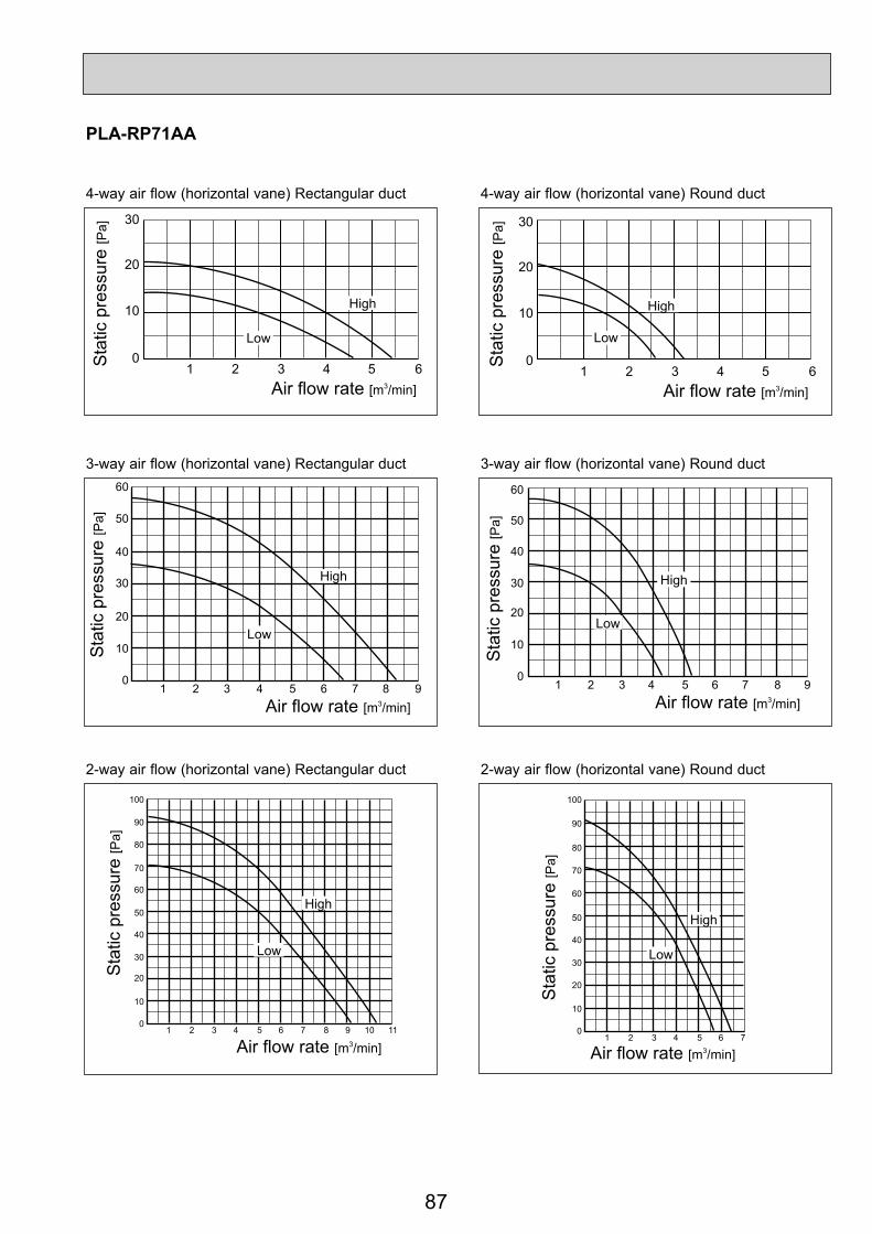
87
30
20
10
01 2 3 4 5 6
Air flow rate [m3/min]
Sta
ticpr
essu
re[P
a]
High
Low
30
20
10
01 2 3 4 5 6
Air flow rate [m3/min]
Sta
ticpr
essu
re[P
a]
High
Low
30
40
50
60
20
10
01 2 3 4 5 6 7 8 9
Air flow rate [m3/min]
High
Low
Sta
ticpr
essu
re[P
a]
30
40
50
60
20
10
01 2 3 4 5 6 7 8 9
Air flow rate [m3/min]
Sta
ticpr
essu
re[P
a]
High
Low
30
40
50
60
70
80
90
100
20
10
01 2 3 4 5 6 7 8 9 10 11
Air flow rate [m3/min]
High
Low
Sta
ticpr
essu
re[P
a]
30
40
50
60
70
80
90
100
20
10
01 2 3 4 5 6 7
Air flow rate [m3/min]
High
Low
Sta
tic p
ress
ure
[Pa]
PLA-RP71AA
4-way air flow (horizontal vane) Rectangular duct 4-way air flow (horizontal vane) Round duct
3-way air flow (horizontal vane) Rectangular duct 3-way air flow (horizontal vane) Round duct
2-way air flow (horizontal vane) Rectangular duct 2-way air flow (horizontal vane) Round duct

88
30
40
50
20
10
01 2 3 4 5 6 7 8 9 10
Air flow rate [m3/min]
Low
High
Sta
tic p
ress
ure
[Pa]
30
40
50
20
10
01 2 3 4 5 6 7 8 9 10
Air flow rate [m3/min]
Sta
tic p
ress
ure
[Pa]
High
Low
30
40
50
60
70
80
90
100
20
10
01 2 3 4 5 6 7 8 9 10 11 12 13 14
Air flow rate [m3/min]
High
Low
Sta
tic p
ress
ure
[Pa]
30
40
50
60
70
80
90
100
20
10
01 2 3 4 5 6 7 8 9 10 11 12 13 14
Air flow rate [m3/min]
Low
Sta
tic p
ress
ure
[Pa]
High
30
40
50
60
70
80
90
100
110
120
20
10
01 2 3 4 5 6 7 8 9 10 11 12 13 14 15 16
Air flow rate [m3/min]
Sta
tic p
ress
ure
[Pa]
High
Low30
40
50
60
70
80
90
100
110
120
20
10
01 2 3 4 5 6 7 8 9 10 11 12 13 14 15 16
Air flow rate [m3/min]
LowSta
tic p
ress
ure
High
PLA-RP100AA2
4-way air flow (horizontal vane) Rectangular duct 4-way air flow (horizontal vane) Round duct
3-way air flow (horizontal vane) Rectangular duct 3-way air flow (horizontal vane) Round duct
2-way air flow (horizontal vane) Rectangular duct 2-way air flow (horizontal vane) Round duct

89
30
40
50
20
10
01 2 3 4 5 6 7 8 9 10
Air flow rate [m3/min]
Low
High
Sta
tic p
ress
ure
[Pa]
30
40
50
20
10
01 2 3 4 5 6 7 8 9 10
Air flow rate [m3/min]
Sta
tic p
ress
ure
[Pa]
High
Low
30
40
50
60
70
80
90
100
20
10
01 2 3 4 5 6 7 8 9 10 11 12 13 14
Air flow rate [m3/min]
Sta
tic p
ress
ure
[Pa]
High
Low 30
40
50
60
70
80
90
100
20
10
01 2 3 4 5 6 7 8 9 10 11 12 13 14
Air flow rate [m3/min]
High
Low
Sta
tic p
ress
ure
[Pa]
30
40
50
60
70
80
90
100
110
120
20
10
01 2 3 4 5 6 7 8 9 10 11 12 13 14 15 16
Air flow rate [m3/min]
High
LowSta
tic p
ress
ure
[Pa]
30
40
50
60
70
80
90
100
110
120
20
10
01 2 3 4 5 6 7 8 9 10 11 12 13 14 15 16
Air flow rate [m3/min]
Sta
tic p
ress
ure[
Pa]
HighLow
PLA-RP125AA2PLA-RP140AA2
4-way air flow (horizontal vane) Rectangular duct 4-way air flow (horizontal vane) Round duct
3-way air flow (horizontal vane) Rectangular duct 3-way air flow (horizontal vane) Round duct
2-way air flow (horizontal vane) Rectangular duct 2-way air flow (horizontal vane) Round duct

90
50.0
-50.0
-100.00.0 0.5 1.0
Air flow (m3/min)
2 intakes
1 intake
Characteristic diagram of air capacity taken from outside
Sta
tic p
ress
ure
(Pa)
1.5 2.0 2.5
0.0
Q…Planned amount of fresh air intake <m³/min>
A…Static pressure loss of fresh air intake duct system with air flow amount Q <Pa>
B…Forced static pressure at air conditioner inlet with air flow amount Q <Pa>
C…Static pressure of booster fan with air flow amount Q <Pa>
D…Static pressure loss increase amount of fresh air intake duct system for air flow amount Q <Pa>
E…Static pressure of indoor unit with air flow amount Q <Pa>
Qa…Estimated amount of fresh air intake without D <m³/min>
(Knockout)
4- 2.8
Flesh air intake hole(Knockout)
Flesh air intake hole
90
122100
108
250 288.5
PMH-P25BA
PMH-P35BA
PMH-P50BA
8.4m3/min
10.0m3/min
11.0m3/min
1.6m3/min
2.0m3/min
2.2m3/min
Air flow(Hi)
Air capacity taken outside
Q
0
BA C
Curve in thegraph below.
Duct characteristicsat site
Q
AE
C
QQa
AD
How to read curves
9-4. PMH-P·BAAir capacity taken from outsidePMH-P·BA series is possible to take outside air.When taking air from the outside, the duct fan can be used.The air capacity should be 20% or less of the air flow SPEC(Hi).

91
9-5. PCA-RP·KAFresh air intake amount & static pressure characteristics
PCA-RP50KA PCA-RP60, 71KA■
500-50-100-150-200-250-300
Sta
tic p
ress
ure[
Pa]
Airflow rate[m³/min]
0 1 2 3 4
500-50-100-150-200-250-300
Sta
tic p
ress
ure[
Pa]
Airflow rate[m³/min]
0 1 2 3 4
500-50-100-150-200-250-300
Sta
tic p
ress
ure[
Pa]
Airflow rate[m³/min]
0 1 2 3 4
■
PCA-RP100, 125, 140KA■
Q…Designed amount of fresh air intake<m3/min>
A…Static pressure loss of fresh airintake duct system with airflowamount Q <Pa>
B…Forced static pressure at air conditionerinlet with airflow amount Q <Pa>
C…Static pressure of booster fan withairflow amount Q <Pa>
D…Static pressure loss increase amountof fresh air intake duct system forairflow amount Q <Pa>
E…Static pressure of indoor unit withairflow amount Q <Pa>
Qa…Estimated amount of fresh airintake without D <m3/min>
How to read curves
Q
0
BA C
1 Curve in thegraphs
Duct characteristicsat site
Q
AE
C2
QQa
AD
3
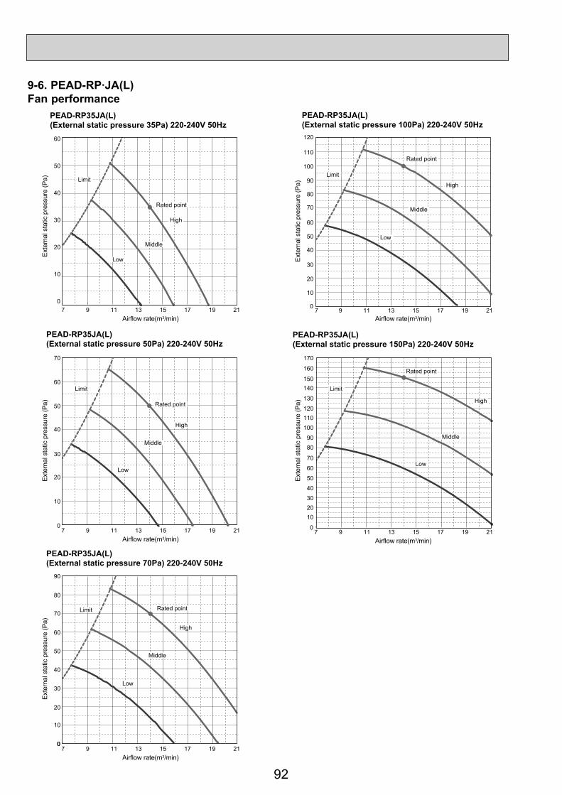
92
9-6. PEAD-RP·JA(L)Fan performance
PEAD-RP35JA(L)(External static pressure 35Pa) 220-240V 50Hz
PEAD-RP35JA(L)(External static pressure 100Pa) 220-240V 50Hz
PEAD-RP35JA(L)(External static pressure 50Pa) 220-240V 50Hz
PEAD-RP35JA(L)(External static pressure 150Pa) 220-240V 50Hz
PEAD-RP35JA(L)(External static pressure 70Pa) 220-240V 50Hz
60
Limit
Rated point
High
Middle
Low
7 9 11 13 15 17 19 21
50
40
30
20
10
0
Airflow rate(m3/min)
7 9 11 13 15 17 19 21Airflow rate(m3/min)
7 9 11 13 15 17 19 21Airflow rate(m3/min)
Exte
rnal
stat
icpr
essu
re(P
a)
60
70
50
40
30
20
10
0
7 9 11 13 15 17 19 21Airflow rate(m3/min)
0
Exte
rnal
stat
icpr
essu
re(P
a)
8090
100110120
130
140150
160
170
70
40
50
60
102030
0
Exte
rnal
stat
icpr
essu
re(P
a)
60
70
80
90
50
40
30
20
10
0
Exte
rnal
stat
ic p
ress
ure
(Pa)
7 9 11 13 15 17 19 21Airflow rate(m3/min)
60
70
80
90
100
110
120
50
40
30
20
10
0Ex
tern
alst
atic
pres
sure
(Pa)
Limit
Rated point
High
Middle
Low
Limit Rated point
High
Middle
Low
Limit
Rated point
High
Middle
Low
Limit
Rated point
High
Middle
Low

93
PEAD-RP50JA(L)(External static pressure 35Pa) 220-240V 50Hz
PEAD-RP50JA(L)(External static pressure 100Pa) 220-240V 50Hz
PEAD-RP50JA(L)(External static pressure 50Pa) 220-240V 50Hz
PEAD-RP50JA(L)(External static pressure 150Pa) 220-240V 50Hz
PEAD-RP50JA(L)(External static pressure 70Pa) 220-240V 50Hz
Airflow rate(m3/min)
Airflow rate(m3/min)Airflow rate(m3/min)
60
70
50
40
30
20
10
0
Exte
rnal
stat
icpr
essu
re(P
a)
Airflow rate(m3/min)
60
70
80
50
40
30
20
10
0
Exte
rnal
stat
icpr
essu
re(P
a)
8090
100110
120130140150160170180
70
4050
60
102030
0
Exte
rnal
stat
icpr
essu
re(P
a)
0
60
70
80
90
100
50
40
30
20
10
Exte
rnal
stat
ic p
ress
ure
(Pa)
91419Airflow rate(m3/min)
60
70
80
90
100
110
120
130
50
40
30
20
10
0
Exte
rnal
stat
icpr
essu
re(P
a)
Rated point
High
Middle
Low
Limit
Rated point
High
Middle
Low
LimitRated point
High
Middle
Low
Limit
Rated point
High
Middle
Low
Limit Rated point
High
Middle
Low
Limit
91419
91419
91419
91419

94
PEAD-RP60JA(L)(External static pressure 35Pa) 220-240V 50Hz
PEAD-RP60JA(L)(External static pressure 100Pa) 220-240V 50Hz
PEAD-RP60JA(L)(External static pressure 50Pa) 220-240V 50Hz
PEAD-RP60JA(L)(External static pressure 150Pa) 220-240V 50Hz
PEAD-RP60JA(L)(External static pressure 70Pa) 220-240V 50Hz
10 15 20 25 30Airflow rate(m3/min)
10 15 20 25 30Airflow rate(m3/min)
10 15 20 25 30Airflow rate(m3/min)
60
50
40
30
20
10
0
Exte
rnal
stat
icpr
essu
re(P
a)
10 15 20 25 30Airflow rate(m3/min)
60
70
50
40
30
20
10
0
Exte
rnal
stat
icpr
essu
re(P
a)
80
90
100110
120130140
150160
170
70
40
50
60
10
2030
0
Exte
rnal
stat
icpr
essu
re(P
a)
0
60
70
80
90
50
40
30
20
10
Exte
rnal
sta
ticpr
essu
re(P
a)
10 15 20 25 30Airflow rate(m3/min)
60
70
80
90
100
110
120
50
40
30
20
10
0
Exte
rnal
stat
icpr
essu
re(P
a)
Rated point
High
Middle
Low
Limit
Rated point
High
Middle
Low
Limit
Limit
Rated point
High
Middle
Low
Limit
Rated point
High
Middle
Low
Limit
Rated point
High
Middle
Low

95
PEAD-RP71JA(L)(External static pressure 35Pa) 220-240V 50Hz
PEAD-RP71JA(L)(External static pressure 100Pa) 220-240V 50Hz
PEAD-RP71JA(L)(External static pressure 50Pa) 220-240V 50Hz
PEAD-RP71JA(L)(External static pressure 150Pa) 220-240V 50Hz
PEAD-RP71JA(L)(External static pressure 70Pa) 220-240V 50Hz
15 20 25 30Airflow rate(m3/min)
10 15 20 25 30Airflow rate(m3/min)
70
60
50
40
30
20
10
0
Exte
rnal
stat
icpr
essu
re(P
a)
10 15 20 25 30Airflow rate(m3/min)
60
70
80
90
50
40
30
20
10
0
Exte
rnal
stat
icpr
essu
re(P
a)
10
8090
100110120130140150
160170180
70
405060
102030
0
Exte
rnal
stat
icpr
essu
re(P
a)
10 15 20 25 30Airflow rate(m3/min)
0
60
70
80
90
100
50
40
30
20
10
Exte
rnal
sta
ticpr
essu
re(P
a)
10 15 20 25 30Airflow rate(m3/min)
60
70
80
90
100
110
120
130
50
40
30
20
10
0
Exte
rnal
stat
icpr
essu
re(P
a)
Rated point
High
Middle
Low
Limit
Rated point
High
Middle
Low
Limit
Limit Rated point
High
Middle
Low
Rated point
High
Middle
Low
Limit
Limit
Rated pointHigh
Middle
Low

96
PEAD-RP100JA(L)(External static pressure 35Pa) 220-240V 50Hz
PEAD-RP100JA(L)(External static pressure 100Pa) 220-240V 50Hz
PEAD-RP100JA(L)(External static pressure 50Pa) 220-240V 50Hz
PEAD-RP100JA(L)(External static pressure 150Pa) 220-240V 50Hz
PEAD-RP100JA(L)(External static pressure 70Pa) 220-240V 50Hz
10 15 20 25 30 35 40 45Airflow rate(m3/min)
70
60
50
40
30
20
10
0
Exte
rnal
stat
icpr
essu
re(P
a)
10 15 20 25 30 35 40 45Airflow rate(m3/min)
60
70
80
90
100
50
40
30
20
10
0
Exte
rnal
stat
icpr
essu
re(P
a)
15 20 25 30 35 40 45Airflow rate(m3/min)
10
8090
100110120130140150160170180190200
70
405060
102030
0
Exte
rnal
stat
icpr
essu
re(P
a)
10 15 20 25 30 35 40 45Airflow rate(m3/min)
0
60
70
80
90
100
110
120
50
40
30
20
10
Exte
rnal
sta
ticpr
essu
re(P
a)
10 15 20 25 30 35 40 45Airflow rate(m3/min)
60
70
80
90
100
110
120
130
140
150
50
40
30
20
10
0
Exte
rnal
stat
icpr
essu
re(P
a)
Limit
Rated point
High
Middle
Low
Rated point
High
Middle
Low
Limit
Rated point
High
Middle
Low
Limit
Rated point
High
Middle
Low
Limit
Rated point
High
Middle
Low
Limit
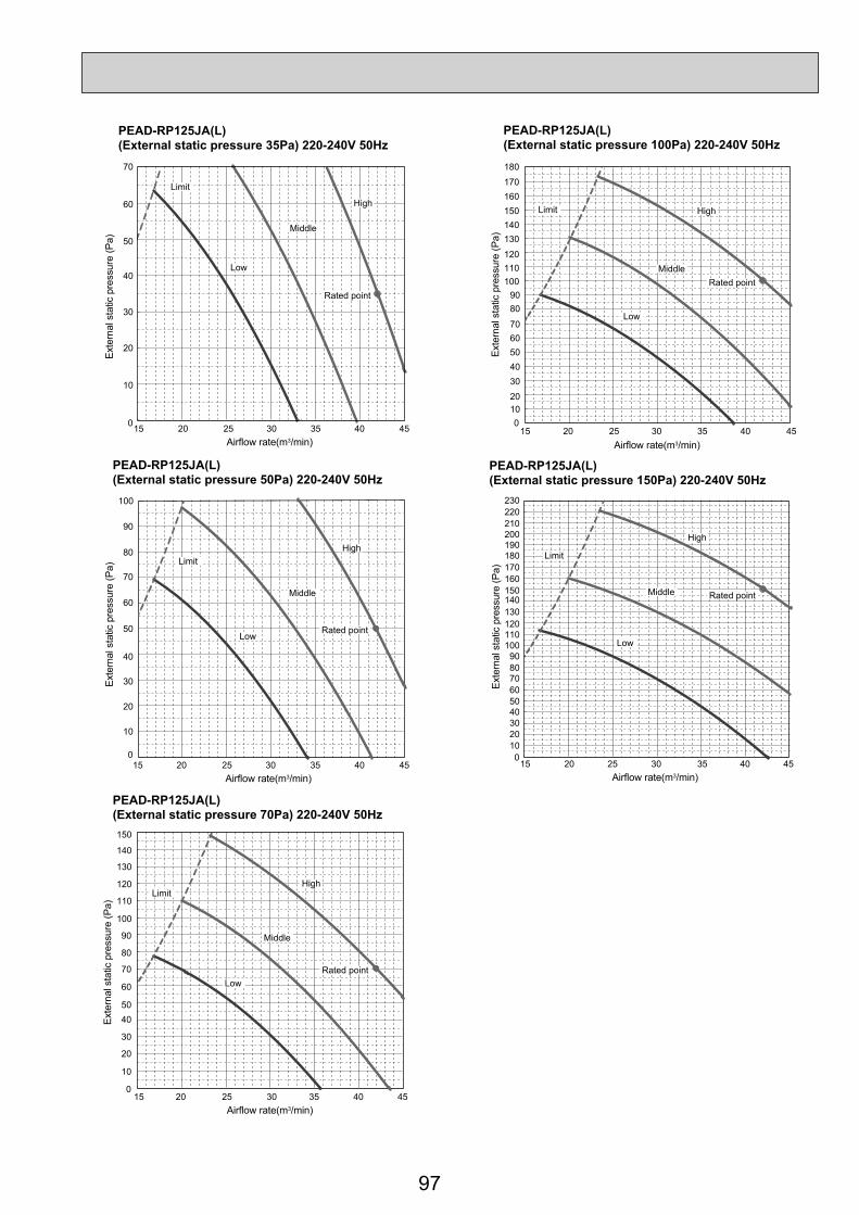
97
PEAD-RP125JA(L)(External static pressure 35Pa) 220-240V 50Hz
PEAD-RP125JA(L)(External static pressure 100Pa) 220-240V 50Hz
PEAD-RP125JA(L)(External static pressure 50Pa) 220-240V 50Hz
PEAD-RP125JA(L)(External static pressure 150Pa) 220-240V 50Hz
PEAD-RP125JA(L)(External static pressure 70Pa) 220-240V 50Hz
15 20 25 30 35 40 45Airflow rate(m3/min)
6070
8090
100110120
130140150160170
180
50403020100
Exte
rnal
stat
icpr
essu
re(P
a)
Rated point
High
Middle
Low
Limit
20 25 30 35 40 45Airflow rate(m3/min)
15
8090
100110120130140150160170180190200210220230
70
405060
102030
0
Exte
rnal
stat
icpr
essu
re(P
a)
Rated point
High
Middle
Low
Limit
15 20 25 30 35 40 45Airflow rate(m3/min)
70
60
50
40
30
20
10
0
Exte
rnal
stat
icpr
essu
re(P
a)
Rated point
High
Middle
Low
Limit
15 20 25 30 35 40 45Airflow rate(m3/min)
60
70
80
90
100
50
40
30
20
10
0
Exte
rnal
stat
icpr
essu
re(P
a)
Rated point
High
Middle
Low
Limit
15 20 25 30 35 40 45Airflow rate(m3/min)
0
60
70
80
90
100
110
120
130
140
150
5040
30
20
10
Exte
rnal
stat
ic p
ress
ure
(Pa)
Limit
Rated point
High
Middle
Low
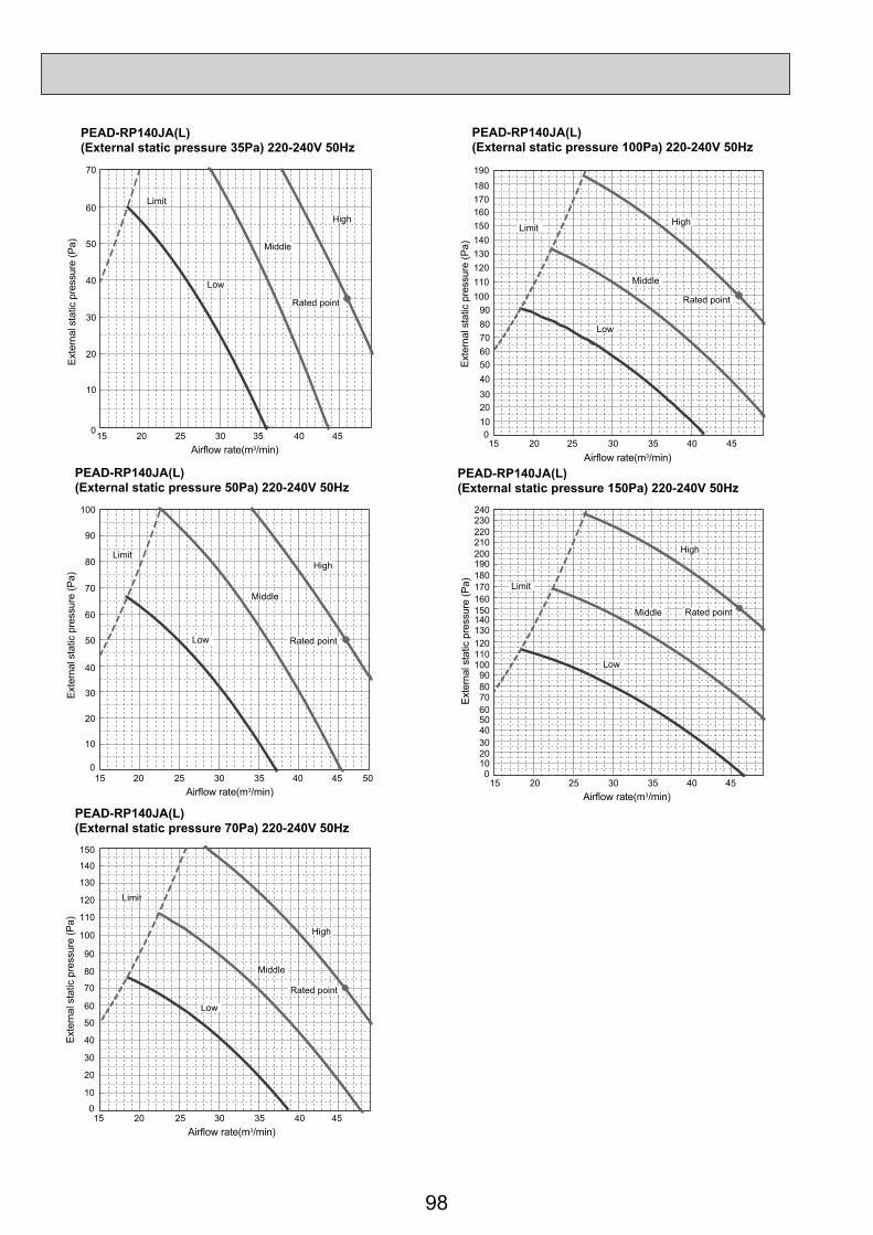
98
PEAD-RP140JA(L)(External static pressure 35Pa) 220-240V 50Hz
PEAD-RP140JA(L)(External static pressure 100Pa) 220-240V 50Hz
PEAD-RP140JA(L)(External static pressure 50Pa) 220-240V 50Hz
PEAD-RP140JA(L)(External static pressure 150Pa) 220-240V 50Hz
PEAD-RP140JA(L)(External static pressure 70Pa) 220-240V 50Hz
15 20 25 30 35 40 45Airflow rate(m3/min)
60708090
100110120130140150160170180
190
50403020100
Exte
rnal
stat
icpr
essu
re(P
a)
20 25 30 35 40 45Airflow rate(m3/min)
15
8090
100110120130140150160170180190200210220230240
70
405060
102030
0
Exte
rnal
stat
icpr
essu
re(P
a)
15 20 25 30 35 40 45Airflow rate(m3/min)
70
60
50
40
30
20
10
0
Exte
rnal
stat
icpr
essu
re(P
a)
15 20 25 30 35 40 5045Airflow rate(m3/min)
60
70
80
90
100
50
40
30
20
10
0
Exte
rnal
stat
icpr
essu
re(P
a)
15 20 25 30 35 40 45Airflow rate(m3/min)
0
60
70
80
90
100
110
120
130
140
150
50
40
30
20
10
Exte
rnal
sta
ticpr
essu
re(P
a)
Rated point
High
Middle
Low
Limit
Rated point
High
Middle
Low
Limit
Rated point
High
Middle
Low
Limit
Rated point
High
Middle
Low
Limit
Rated point
High
Middle
Low
Limit

99
9-7. PEAD-RP·EA,EA2,GA9-7-1. FAN PERFORMANCE AND CORRECTED AIR FLOWPEAD-RP35EA2PEAD-RP50EA
PEAD-RP60EA
Fan Performance <30Pa>
Exte
rnal
sta
tic p
ress
ure
(Pa)
(1Pa
0
.1m
mAq
)
Air Flow (CMM)8 10 12 14 16 18 20 22 24
12 14 16 18 20 22 24 2620
40
60
80
100
120
0.8
0.9
1.0
1.1
Corrected Air Flow Capacityinput
Cooling
Air flow (CMM)
Cor
rect
ion
fact
or
Fan Performance <70Pa>
Exte
rnal
sta
tic p
ress
ure
(Pa)
(1Pa
0
.1m
mAq
)
Air Flow (CMM)10 12 14 16 18 20 22 24 26
12 14 16 18 20 22 24 2620
40
60
80
100
120
140
0.8
0.9
1.0
1.1
1.2
1.3Heating
Air flow (CMM)
Cor
rect
ion
fact
or
Fan Performance <30Pa>
Exte
rnal
sta
tic p
ress
ure
(Pa)
(1Pa
0
.1m
mAq
)
Air Flow (CMM)6 8 10 12 14 16 18 20
8 10 12 14 16 18 20 2220
40
60
80
100
120
140
0.8
0.9
1.0
1.1
Corrected Air Flow Capacityinput
Cooling
Air flow (CMM)
Cor
rect
ion
fact
or
Fan Performance <70Pa>
Exte
rnal
sta
tic p
ress
ure
(Pa)
(1Pa
0
.1m
mAq
)
Air Flow (CMM)8 10 12 14 16 18 20 22
8 10 12 14 16 18 20 2220
40
60
80
100
120
140
160
0.8
0.9
1.0
1.1
1.2
1.3Heating
Air flow (CMM)
Cor
rect
ion
fact
or

100
PEAD-RP71EA
LoHi140
120
100
200180
160
80
60
40
20
12 16 20 24 28 32 Air f low (CMM)
Fan performance <130Pa>
Recommended range
Ext
erna
l st
atic
pre
ssur
e (P
a)
(1P
a
0.1m
mA
q)
140120
100
180
160
80
60
40
20
12 16 20 24 28 32 Air f low (CMM)
Fan performance <70Pa>
Recommended range
Ext
erna
l st
atic
pre
ssur
e (P
a)
(1P
a
0.1m
mA
q)=
LoHi
Corrected Air Flow CapacityInput
1.1
1.0
0.9
0.8
12 16 20 24 28 32
Air flow (CMM)
Cor
rect
ion
fact
or
Cooling
=
1.1
1.0
1.3
1.2
0.9
0.812 16 20 24 28 32
Air flow (CMM)
Cor
rect
ion
fact
or
Heating
PEAD-RP100EA2PEAD-RP125EA
Lo
Hi
140120
100
200
220
180
160
80
60
40
20
32 34 36 38 40 42 44 46 48Air f low (CMM)
Fan performance <130Pa>Recommended range
Ext
erna
l st
atic
pre
ssur
e (P
a)
(1P
a
0.1m
mA
q) 140120
100
200220
180
160
80
60
40
20
32 34 36 38 40 42 44 46 Air f low (CMM)
Fan performance <70Pa>Recommended range
Ext
erna
l st
atic
pre
ssur
e (P
a)
(1P
a
0.1m
mA
q)
Lo
Hi
Corrected Air Flow CapacityInput
1.1
1.0
0.9
0.832 34 36 38 40 42 44 46 48
Air flow (CMM)
Cor
rect
ion
fact
or
Cooling1.1
1.0
1.2
0.9
0.832 34 36 38 40 42 44 46 48
Air flow (CMM)
Cor
rect
ion
fact
or
Heating
= =

101
PEAD-RP140EA
1.2
1.1
1.0
0.9
0.836 38 40 42 44 46 48 50 52
Air flow (CMM)
Cor
rect
ion
fac
tor
HeatingCorrected Air Flow CapacityInput
1.1
1.0
0.9
0.836 38 40 42 44 46 48 50 52
Air flow (CMM)
Cor
rect
ion
fac
tor
Cooling
LoHi
200180
160
140
120
100
80
60
40
20
36 38 40 42 44 46 48 50Air f low (CMM)
Fan performance <70Pa>Recommended range
Ext
erna
l st
atic
pre
ssur
e (P
a)
(1P
a
0.1m
mA
q)=
Lo
200220
180160140120100 80 60 40 20
36 38 40 42 44 46 48 50 52Air f low (CMM)
Fan performance <130Pa>
Recommended range
Ext
erna
l st
atic
pre
ssur
e (P
a)
(1P
a
0.1m
mA
q)= Hi
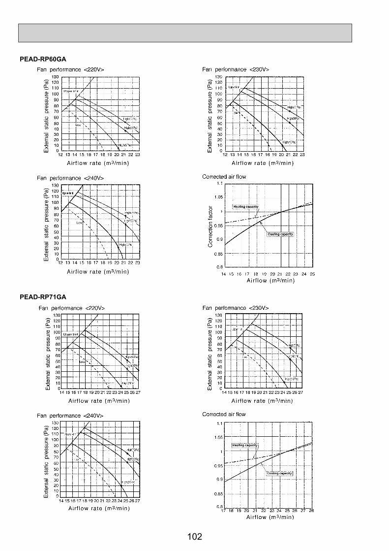
102
PEAD-RP60GA
PEAD-RP71GA

103
PEAD-RP100GA

104
PLA-RP35BA PLA-RP50BANOTCH SPL(dB) LINEHigh 31
Medium1 29Medium2 28
Low 27
NOTCH SPL(dB) LINEHigh 32
Medium1 31Medium2 29
Low 28
90
80
70
60
50
40
30
20
1063 125 250 500 1000 2000 4000 8000
APPROXIMATETHRESHOLD OFHEARING FORCONTINUOUSNOISE
NC-60
NC-50
NC-40
NC-30
NC-20
NC-70
OC
TAVE
BA
ND
SO
UN
D P
RES
SUR
E LE
VEL,
dB
(0 d
B =
0.0
002 μb
ar)
OC
TAVE
BA
ND
SO
UN
D P
RES
SUR
E LE
VEL,
dB
(0 d
B =
0.0
002 μb
ar)
BAND CENTER FREQUENCIES, Hz
90
80
70
60
50
40
30
20
1063 125 250 500 1000 2000 4000 8000
APPROXIMATETHRESHOLD OFHEARING FORCONTINUOUSNOISE
NC-60
NC-50
NC-40
NC-30
NC-20
NC-70
BAND CENTER FREQUENCIES, Hz
PLA-RP60BA PLA-RP71BANOTCH SPL(dB) LINEHigh 32
Medium1 31Medium2 29
Low 28
NOTCH SPL(dB) LINEHigh 34
Medium1 32Medium2 30
Low 28
90
80
70
60
50
40
30
20
1063 125 250 500 1000 2000 4000 8000
APPROXIMATETHRESHOLD OFHEARING FORCONTINUOUSNOISE
NC-60
NC-50
NC-40
NC-30
NC-20
NC-70
BAND CENTER FREQUENCIES, Hz
90
80
70
60
50
40
30
20
1063 125 250 500 1000 2000 4000 8000
APPROXIMATETHRESHOLD OFHEARING FORCONTINUOUSNOISE
NC-60
NC-50
NC-40
NC-30
NC-20
NC-70
BAND CENTER FREQUENCIES, Hz
OC
TAVE
BA
ND
SO
UN
D P
RES
SUR
E LE
VEL,
dB
(0 d
B =
0.0
002 μb
ar)
OC
TAVE
BA
ND
SO
UN
D P
RES
SUR
E LE
VEL,
dB
(0 d
B =
0.0
002 μb
ar)
10 NOISE CRITERION CURVES
10-1. INDOOR UNIT

105105
PLA-RP100BA PLA-RP125BANOTCH SPL(dB) LINEHigh 40
Medium1 37Medium2 34
Low 32
NOTCH SPL(dB) LINEHigh 41
Medium1 39Medium2 36
Low 34
90
80
70
60
50
40
30
20
1063 125 250 500 1000 2000 4000 8000
APPROXIMATETHRESHOLD OFHEARING FORCONTINUOUSNOISE
NC-60
NC-50
NC-40
NC-30
NC-20
NC-70
OC
TAVE
BA
ND
SO
UN
D P
RES
SUR
E LE
VEL,
dB
(0 d
B =
0.0
002 μb
ar)
OC
TAVE
BA
ND
SO
UN
D P
RES
SUR
E LE
VEL,
dB
(0 d
B =
0.0
002 μb
ar)
BAND CENTER FREQUENCIES, Hz
PLA-RP140BAPLA-RP140BA2
NOTCH SPL(dB) LINEHigh 44
Medium1 42Medium2 39
Low 36
90
80
70
60
50
40
30
20
1063 125 250 500 1000 2000 4000 8000
APPROXIMATETHRESHOLD OFHEARING FORCONTINUOUSNOISE
NC-60
NC-50
NC-40
NC-30
NC-20
NC-70
OC
TAVE
BA
ND
SO
UN
D P
RES
SUR
E LE
VEL,
dB
(0 d
B =
0.0
002 μb
ar)
BAND CENTER FREQUENCIES, Hz
90
80
70
60
50
40
30
20
1063 125 250 500 1000 2000 4000 8000
APPROXIMATETHRESHOLD OFHEARING FORCONTINUOUSNOISE
NC-60
NC-50
NC-40
NC-30
NC-20
NC-70
BAND CENTER FREQUENCIES, Hz
UNIT
1.5m
MICROPHONE
CEILING

106
PLA-RP35AA PLA-RP50AAPLA-RP60AA
NOTCH SPL(dB) LINEHigh
Medium1Medium2
Low
HighMedium1Medium2
Low
31292827
NOTCH SPL(dB) LINE33312928
90
80
70
60
50
40
30
20
1063 125 250 500 1000 2000 4000 8000
APPROXIMATETHRESHOLD OFHEARING FORCONTINUOUSNOISE
NC-60
NC-50
NC-40
NC-30
NC-20
NC-70
OC
TAVE
BA
ND
SO
UN
D P
RES
SUR
E LE
VEL,
dB
(0 d
B =
0.0
002 μb
ar)
OC
TAVE
BA
ND
SO
UN
D P
RES
SUR
E LE
VEL,
dB
(0 d
B =
0.0
002 μb
ar)
BAND CENTER FREQUENCIES, Hz
90
80
70
60
50
40
30
20
1063 125 250 500 1000 2000 4000 8000
APPROXIMATETHRESHOLD OFHEARING FORCONTINUOUSNOISE
NC-60
NC-50
NC-40
NC-30
NC-20
NC-70
BAND CENTER FREQUENCIES, Hz
PLA-RP71AA PLA-RP100AA2NOTCH SPL(dB) LINE
34323028
NOTCH SPL(dB) LINE41393633
90
80
70
60
50
40
30
20
1063 125 250 500 1000 2000 4000 8000
APPROXIMATETHRESHOLD OFHEARING FORCONTINUOUSNOISE
NC-60
NC-50
NC-40
NC-30
NC-20
NC-70
BAND CENTER FREQUENCIES, Hz
90
80
70
60
50
40
30
20
1063 125 250 500 1000 2000 4000 8000
APPROXIMATETHRESHOLD OFHEARING FORCONTINUOUSNOISE
NC-60
NC-50
NC-40
NC-30
NC-20
NC-70
BAND CENTER FREQUENCIES, Hz
HighMedium1Medium2
Low
HighMedium1Medium2
Low
OC
TAVE
BA
ND
SO
UN
D P
RES
SUR
E LE
VEL,
dB
(0 d
B =
0.0
002 μb
ar)
OC
TAVE
BA
ND
SO
UN
D P
RES
SUR
E LE
VEL,
dB
(0 d
B =
0.0
002 μb
ar)

107
PLA-RP125AA2 PLA-RP140AA2NOTCH SPL(dB) LINE
45434037
NOTCH SPL(dB) LINE45434037
90
80
70
60
50
40
30
20
1063 125 250 500 1000 2000 4000 8000
APPROXIMATETHRESHOLD OFHEARING FORCONTINUOUSNOISE
NC-60
NC-50
NC-40
NC-30
NC-20
NC-70
OC
TAVE
BA
ND
SO
UN
D P
RES
SUR
E LE
VEL,
dB
(0 d
B =
0.0
002 μb
ar)
OC
TAVE
BA
ND
SO
UN
D P
RES
SUR
E LE
VEL,
dB
(0 d
B =
0.0
002 μb
ar)
BAND CENTER FREQUENCIES, Hz
90
80
70
60
50
40
30
20
1063 125 250 500 1000 2000 4000 8000
APPROXIMATETHRESHOLD OFHEARING FORCONTINUOUSNOISE
NC-60
NC-50
NC-40
NC-30
NC-20
NC-70
BAND CENTER FREQUENCIES, Hz
HighMedium1Medium2
Low
HighMedium1Medium2
Low
UNIT
1.5m
MICROPHONE
CEILING

108
90
80
70
60
50
40
30
20
1063 125 250 500 1000 2000 4000 8000
APPROXIMATETHRESHOLD OFHEARING FORCONTINUOUSNOISE
NC-60
NC-50
NC-40
NC-30
NC-20
NC-70
OC
TAVE
BA
ND
SO
UN
D P
RES
SUR
E LE
VEL,
dB
(0 d
B =
0.0
002 μb
ar)
BAND CENTER FREQUENCIES, Hz
PMH-P35BAHigh
NOTCH
Medium1Medium2
Low
40SPL(dB)
383634
LINE
90
80
70
60
50
40
30
20
1063 125 250 500 1000 2000 4000 8000
APPROXIMATE THRESHOLD OFHEARING FOR CONTINUOUSNOISE
NC-60
NC-50
NC-40
NC-30
NC-20
NC-70
OC
TAVE
BA
ND
SO
UN
D P
RES
SUR
E LE
VEL,
dB
(0 d
B =
0.0
002 μb
ar)
BAND CENTER FREQUENCIES, Hz
PMH-P25BAHigh
NOTCH
Medium1Medium2
Low
35SPL(dB)
333129
LINE
UNIT
1.5m
MICROPHONE
CEILING90
80
70
60
50
40
30
20
1063 125 250 500 1000 2000 4000 8000
APPROXIMATETHRESHOLD OFHEARING FORCONTINUOUSNOISE
NC-60
NC-50
NC-40
NC-30
NC-20
NC-70
OC
TAVE
BA
ND
SO
UN
D P
RES
SUR
E LE
VEL,
dB
(0 d
B =
0.0
002 μb
ar)
BAND CENTER FREQUENCIES, Hz
PMH-P50BAHigh
NOTCH
Medium1Medium2
Low
42SPL(dB)
403836
LINE

109
Measurement location
2m
Ceiling concealed
2m
1.5m
Aux.duct
PEAD-RP·JA(L)
Noise level at anechoic room (Low-Middle-High) Unit: dB(A)
ModelExrernal static pressure
35Pa 50Pa 70Pa 100Pa 150PaPEAD-RP35JA(L) 23-26-29 23-27-30 24-28-31 26-29-33 29-33-37PEAD-RP50JA(L) 25-30-34 26-31-35 28-32-36 29-33-37 31-35-39PEAD-RP60JA(L) 25-28-32 25-29-33 26-30-34 27-31-35 29-34-38PEAD-RP71JA(L) 25-29-34 26-30-34 27-31-35 28-32-36 30-35-39PEAD-RP100JA(L) 28-33-38 29-34-38 30-35-39 31-36-40 34-40-43PEAD-RP125JA(L) 31-36-40 33-36-40 33-37-41 34-39-42 37-41-45PEAD-RP140JA(L) 33-37-43 34-38-43 34-39-44 36-40-45 38-42-46

110
External static pressure 35Pa
External static pressure 50Pa
External static pressure 70Pa
HighMiddle
Low80
70
60
50
40
30
20
10
0 63 125 250 500 1000 2000 4000 8000
NC-60
NC-50
NC-40
NC-30
NC-20
NC-70
OC
TAVE
BAN
D S
OU
ND
PR
ESSU
RE
LEVE
L, d
B (0
dB
= 0.
0002
μba
r)
BAND CENTER FREQUENCIES, Hz
HighMiddle
Low80
70
60
50
40
30
20
10
0 63 125 250 500 1000 2000 4000 8000
NC-60
NC-50
NC-40
NC-30
NC-20
NC-70
OCT
AVE
BAND
SO
UND
PRES
SURE
LEV
EL, d
B (0
dB
= 0.
0002
μba
r)
BAND CENTER FREQUENCIES, Hz
HighMiddle
Low80
70
60
50
40
30
20
10
0 63 125 250 500 1000 2000 4000 8000
Approximateminimum audiblelimit on continuousnoise
NC-60
NC-50
NC-40
NC-30
NC-20
NC-70
OCT
AVE
BAND
SO
UND
PRES
SURE
LEV
EL, d
B (0
dB
= 0.
0002
μba
r)
BAND CENTER FREQUENCIES, Hz
Approximateminimum audiblelimit on continuousnoise
Approximateminimum audiblelimit on continuousnoise
External static pressure 100Pa
External static pressure 150Pa
HighMiddle
Low80
70
60
50
40
30
20
10
0 63 125 250 500 1000 2000 4000 8000
NC-60
NC-50
NC-40
NC-30
NC-20
NC-70
OC
TAVE
BAN
D S
OU
ND
PR
ESSU
RE
LEVE
L, d
B (0
dB
= 0.
0002
μba
r)BAND CENTER FREQUENCIES, Hz
HighMiddle
Low80
70
60
50
40
30
20
10
0 63 125 250 500 1000 2000 4000 8000
NC-60
NC-50
NC-40
NC-30
NC-20
NC-70
OCT
AVE
BAND
SO
UND
PRES
SURE
LEV
EL, d
B (0
dB
= 0.
0002
μba
r)
BAND CENTER FREQUENCIES, Hz
Approximateminimum audiblelimit on continuousnoise
Approximateminimum audiblelimit on continuousnoise
PEAD-RP35JA(L)

111
PEAD-RP50JA(L)External static pressure 35Pa
External static pressure 50Pa
External static pressure 70Pa
HighMiddle
Low80
70
60
50
40
30
20
10
0 63 125 250 500 1000 2000 4000 8000
NC-60
NC-50
NC-40
NC-30
NC-20
NC-70
OC
TAVE
BAN
D S
OU
ND
PR
ESSU
RE
LEVE
L, d
B (0
dB
= 0.
0002
μba
r)
BAND CENTER FREQUENCIES, Hz
HighMiddle
Low80
70
60
50
40
30
20
10
0 63 125 250 500 1000 2000 4000 8000
NC-60
NC-50
NC-40
NC-30
NC-20
NC-70
OCT
AVE
BAND
SO
UND
PRES
SURE
LEV
EL, d
B (0
dB
= 0.
0002
μba
r)
BAND CENTER FREQUENCIES, Hz
HighMiddle
Low80
70
60
50
40
30
20
10
0 63 125 250 500 1000 2000 4000 8000
Approximateminimum audiblelimit on continuousnoise
NC-60
NC-50
NC-40
NC-30
NC-20
NC-70
OCT
AVE
BAND
SO
UND
PRES
SURE
LEV
EL, d
B (0
dB
= 0.
0002
μba
r)
BAND CENTER FREQUENCIES, Hz
Approximateminimum audiblelimit on continuousnoise
Approximateminimum audiblelimit on continuousnoise
External static pressure 100Pa
External static pressure 150Pa
HighMiddleLow
80
70
60
50
40
30
20
10
0 63 125 250 500 1000 2000 4000 8000
NC-60
NC-50
NC-40
NC-30
NC-20
NC-70
OC
TAVE
BAN
D S
OU
ND
PR
ESSU
RE
LEVE
L, d
B (0
dB
= 0.
0002
μba
r)
BAND CENTER FREQUENCIES, Hz
HighMiddleLow
80
70
60
50
40
30
20
10
0 63 125 250 500 1000 2000 4000 8000
NC-60
NC-50
NC-40
NC-30
NC-20
NC-70
OCT
AVE
BAND
SO
UND
PRES
SURE
LEV
EL, d
B (0
dB
= 0.
0002
μba
r)
BAND CENTER FREQUENCIES, Hz
Approximateminimum audiblelimit on continuousnoise
Approximateminimum audiblelimit on continuousnoise

112
External static pressure 35Pa
External static pressure 50Pa
External static pressure 70Pa
HighMiddle
Low80
70
60
50
40
30
20
10
0 63 125 250 500 1000 2000 4000 8000
NC-60
NC-50
NC-40
NC-30
NC-20
NC-70
OC
TAVE
BAN
D S
OU
ND
PR
ESSU
RE
LEVE
L, d
B (0
dB
= 0.
0002
μba
r)
BAND CENTER FREQUENCIES, Hz
HighMiddle
Low80
70
60
50
40
30
20
10
0 63 125 250 500 1000 2000 4000 8000
NC-60
NC-50
NC-40
NC-30
NC-20
NC-70
OCT
AVE
BAND
SO
UND
PRES
SURE
LEV
EL, d
B (0
dB
= 0.
0002
μba
r)
BAND CENTER FREQUENCIES, Hz
HighMiddle
Low80
70
60
50
40
30
20
10
0 63 125 250 500 1000 2000 4000 8000
Approximateminimum audiblelimit on continuousnoise
NC-60
NC-50
NC-40
NC-30
NC-20
NC-70
OCT
AVE
BAND
SO
UND
PRES
SURE
LEV
EL, d
B (0
dB
= 0.
0002
μba
r)
BAND CENTER FREQUENCIES, Hz
Approximateminimum audiblelimit on continuousnoise
Approximateminimum audiblelimit on continuousnoise
External static pressure 100Pa
External static pressure 150Pa
HighMiddle
Low80
70
60
50
40
30
20
10
0 63 125 250 500 1000 2000 4000 8000
NC-60
NC-50
NC-40
NC-30
NC-20
NC-70
OC
TAVE
BAN
D S
OU
ND
PR
ESSU
RE
LEVE
L, d
B (0
dB
= 0.
0002
μba
r)BAND CENTER FREQUENCIES, Hz
HighMiddle
Low80
70
60
50
40
30
20
10
0 63 125 250 500 1000 2000 4000 8000
NC-60
NC-50
NC-40
NC-30
NC-20
NC-70
OCT
AVE
BAND
SO
UND
PRES
SURE
LEV
EL, d
B (0
dB
= 0.
0002
μba
r)
BAND CENTER FREQUENCIES, Hz
Approximateminimum audiblelimit on continuousnoise
Approximateminimum audiblelimit on continuousnoise
PEAD-RP60JA(L)

113
PEAD-RP71JA(L)External static pressure 35Pa
External static pressure 50Pa
External static pressure 70Pa
HighMiddle
Low80
70
60
50
40
30
20
10
0 63 125 250 500 1000 2000 4000 8000
NC-60
NC-50
NC-40
NC-30
NC-20
NC-70
OC
TAVE
BAN
D S
OU
ND
PR
ESSU
RE
LEVE
L, d
B (0
dB
= 0.
0002
μba
r)
BAND CENTER FREQUENCIES, Hz
HighMiddle
Low80
70
60
50
40
30
20
10
0 63 125 250 500 1000 2000 4000 8000
NC-60
NC-50
NC-40
NC-30
NC-20
NC-70
OCT
AVE
BAND
SO
UND
PRES
SURE
LEV
EL, d
B (0
dB
= 0.
0002
μba
r)
BAND CENTER FREQUENCIES, Hz
HighMiddle
Low80
70
60
50
40
30
20
10
0 63 125 250 500 1000 2000 4000 8000
Approximateminimum audiblelimit on continuousnoise
NC-60
NC-50
NC-40
NC-30
NC-20
NC-70
OCT
AVE
BAND
SO
UND
PRES
SURE
LEV
EL, d
B (0
dB
= 0.
0002
μba
r)
BAND CENTER FREQUENCIES, Hz
Approximateminimum audiblelimit on continuousnoise
Approximateminimum audiblelimit on continuousnoise
External static pressure 100Pa
External static pressure 150Pa
HighMiddleLow
80
70
60
50
40
30
20
10
0 63 125 250 500 1000 2000 4000 8000
NC-60
NC-50
NC-40
NC-30
NC-20
NC-70
OC
TAVE
BAN
D S
OU
ND
PR
ESSU
RE
LEVE
L, d
B (0
dB
= 0.
0002
μba
r)
BAND CENTER FREQUENCIES, Hz
HighMiddleLow
80
70
60
50
40
30
20
10
0 63 125 250 500 1000 2000 4000 8000
NC-60
NC-50
NC-40
NC-30
NC-20
NC-70
OCT
AVE
BAND
SO
UND
PRES
SURE
LEV
EL, d
B (0
dB
= 0.
0002
μba
r)
BAND CENTER FREQUENCIES, Hz
Approximateminimum audiblelimit on continuousnoise
Approximateminimum audiblelimit on continuousnoise

114
PEAD-RP100JA(L)External static pressure 35Pa
External static pressure 50Pa
External static pressure 70Pa
HighMiddle
Low80
70
60
50
40
30
20
10
0 63 125 250 500 1000 2000 4000 8000
NC-60
NC-50
NC-40
NC-30
NC-20
NC-70
OC
TAVE
BAN
D S
OU
ND
PR
ESSU
RE
LEVE
L, d
B (0
dB
= 0.
0002
μba
r)
BAND CENTER FREQUENCIES, Hz
HighMiddle
Low80
70
60
50
40
30
20
10
0 63 125 250 500 1000 2000 4000 8000
NC-60
NC-50
NC-40
NC-30
NC-20
NC-70
OCT
AVE
BAND
SO
UND
PRES
SURE
LEV
EL, d
B (0
dB
= 0.
0002
μba
r)
BAND CENTER FREQUENCIES, Hz
HighMiddle
Low80
70
60
50
40
30
20
10
0 63 125 250 500 1000 2000 4000 8000
Approximateminimum audiblelimit on continuousnoise
NC-60
NC-50
NC-40
NC-30
NC-20
NC-70
OCT
AVE
BAND
SO
UND
PRES
SURE
LEV
EL, d
B (0
dB
= 0.
0002
μba
r)
BAND CENTER FREQUENCIES, Hz
Approximateminimum audiblelimit on continuousnoise
Approximateminimum audiblelimit on continuousnoise
External static pressure 100Pa
External static pressure 150Pa
HighMiddle
Low80
70
60
50
40
30
20
10
0 63 125 250 500 1000 2000 4000 8000
NC-60
NC-50
NC-40
NC-30
NC-20
NC-70
OC
TAVE
BAN
D S
OU
ND
PR
ESSU
RE
LEVE
L, d
B (0
dB
= 0.
0002
μba
r)BAND CENTER FREQUENCIES, Hz
HighMiddle
Low80
70
60
50
40
30
20
10
0 63 125 250 500 1000 2000 4000 8000
NC-60
NC-50
NC-40
NC-30
NC-20
NC-70
OCT
AVE
BAND
SO
UND
PRES
SURE
LEV
EL, d
B (0
dB
= 0.
0002
μba
r)
BAND CENTER FREQUENCIES, Hz
Approximateminimum audiblelimit on continuousnoise
Approximateminimum audiblelimit on continuousnoise
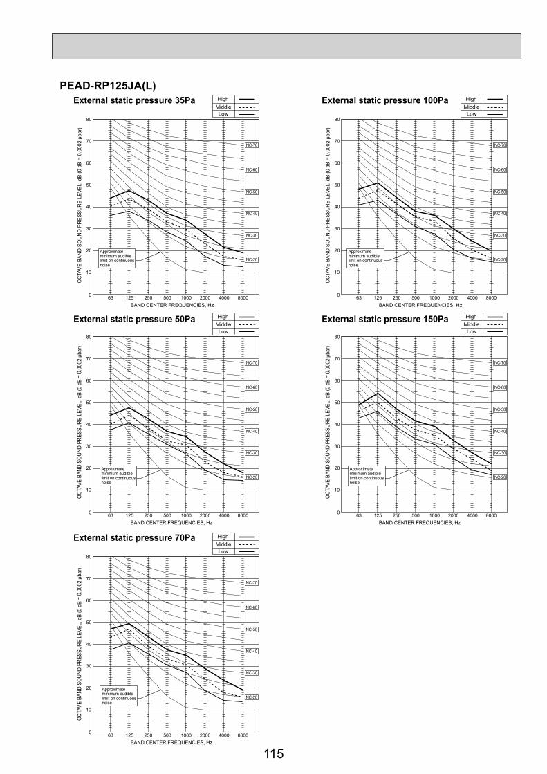
115
PEAD-RP125JA(L)External static pressure 35Pa
External static pressure 50Pa
External static pressure 70Pa
HighMiddle
Low80
70
60
50
40
30
20
10
0 63 125 250 500 1000 2000 4000 8000
NC-60
NC-50
NC-40
NC-30
NC-20
NC-70
OC
TAVE
BAN
D S
OU
ND
PR
ESSU
RE
LEVE
L, d
B (0
dB
= 0.
0002
μba
r)
BAND CENTER FREQUENCIES, Hz
HighMiddle
Low80
70
60
50
40
30
20
10
0 63 125 250 500 1000 2000 4000 8000
NC-60
NC-50
NC-40
NC-30
NC-20
NC-70
OCT
AVE
BAND
SO
UND
PRES
SURE
LEV
EL, d
B (0
dB
= 0.
0002
μba
r)
BAND CENTER FREQUENCIES, Hz
HighMiddle
Low80
70
60
50
40
30
20
10
0 63 125 250 500 1000 2000 4000 8000
Approximateminimum audiblelimit on continuousnoise
NC-60
NC-50
NC-40
NC-30
NC-20
NC-70
OCT
AVE
BAND
SO
UND
PRES
SURE
LEV
EL, d
B (0
dB
= 0.
0002
μba
r)
BAND CENTER FREQUENCIES, Hz
Approximateminimum audiblelimit on continuousnoise
Approximateminimum audiblelimit on continuousnoise
External static pressure 100Pa
External static pressure 150Pa
HighMiddleLow
80
70
60
50
40
30
20
10
0 63 125 250 500 1000 2000 4000 8000
NC-60
NC-50
NC-40
NC-30
NC-20
NC-70
OC
TAVE
BAN
D S
OU
ND
PR
ESSU
RE
LEVE
L, d
B (0
dB
= 0.
0002
μba
r)
BAND CENTER FREQUENCIES, Hz
HighMiddleLow
80
70
60
50
40
30
20
10
0 63 125 250 500 1000 2000 4000 8000
NC-60
NC-50
NC-40
NC-30
NC-20
NC-70
OCT
AVE
BAND
SO
UND
PRES
SURE
LEV
EL, d
B (0
dB
= 0.
0002
μba
r)
BAND CENTER FREQUENCIES, Hz
Approximateminimum audiblelimit on continuousnoise
Approximateminimum audiblelimit on continuousnoise

116
PEAD-RP140JA(L)External static pressure 35Pa
External static pressure 50Pa
External static pressure 70Pa
HighMiddle
Low80
70
60
50
40
30
20
10
0 63 125 250 500 1000 2000 4000 8000
NC-60
NC-50
NC-40
NC-30
NC-20
NC-70
OC
TAVE
BAN
D S
OU
ND
PR
ESSU
RE
LEVE
L, d
B (0
dB
= 0.
0002
μba
r)
BAND CENTER FREQUENCIES, Hz
HighMiddle
Low80
70
60
50
40
30
20
10
0 63 125 250 500 1000 2000 4000 8000
NC-60
NC-50
NC-40
NC-30
NC-20
NC-70
OCT
AVE
BAND
SO
UND
PRES
SURE
LEV
EL, d
B (0
dB
= 0.
0002
μba
r)
BAND CENTER FREQUENCIES, Hz
HighMiddle
Low80
70
60
50
40
30
20
10
0 63 125 250 500 1000 2000 4000 8000
Approximateminimum audiblelimit on continuousnoise
NC-60
NC-50
NC-40
NC-30
NC-20
NC-70
OCT
AVE
BAND
SO
UND
PRES
SURE
LEV
EL, d
B (0
dB
= 0.
0002
μba
r)
BAND CENTER FREQUENCIES, Hz
Approximateminimum audiblelimit on continuousnoise
Approximateminimum audiblelimit on continuousnoise
External static pressure 100Pa
External static pressure 150Pa
HighMiddle
Low80
70
60
50
40
30
20
10
0 63 125 250 500 1000 2000 4000 8000
NC-60
NC-50
NC-40
NC-30
NC-20
NC-70
OC
TAVE
BAN
D S
OU
ND
PR
ESSU
RE
LEVE
L, d
B (0
dB
= 0.
0002
μba
r)BAND CENTER FREQUENCIES, Hz
HighMiddle
Low80
70
60
50
40
30
20
10
0 63 125 250 500 1000 2000 4000 8000
NC-60
NC-50
NC-40
NC-30
NC-20
NC-70
OCT
AVE
BAND
SO
UND
PRES
SURE
LEV
EL, d
B (0
dB
= 0.
0002
μba
r)
BAND CENTER FREQUENCIES, Hz
Approximateminimum audiblelimit on continuousnoise
Approximateminimum audiblelimit on continuousnoise

117
HighLow
HighLow
HighLow
HighLow
NC60
NC50
NC40
NC30
NC20
70
60
50
40
30
20
63 125 250 500 1000 2000 4000 8000
10
0OC
TAV
E B
AN
D P
RE
SS
UR
E L
EV
EL
(dB
) 0dB
= 2
0P
a
OCTAVE BAND CENTER FREQUENCIES (Hz)
Approximate minimum audible limit on continuous noise
NC60
NC50
NC40
NC30
NC20
70
60
50
40
30
20
63 125 250 500 1000 2000 4000 8000
10
0OC
TAV
E B
AN
D P
RE
SS
UR
E L
EV
EL
(dB
) 0dB
= 2
0P
a
OCTAVE BAND CENTER FREQUENCIES (Hz)
Approximate minimum audible limit on continuous noise
NC60
NC50
NC40
NC30
NC20
70
60
50
40
30
20
63 125 250 500 1000 2000 4000 8000
10
0OC
TAV
E B
AN
D P
RE
SS
UR
E L
EV
EL
(dB
) 0dB
= 2
0P
a
OCTAVE BAND CENTER FREQUENCIES (Hz)
Approximate minimum audible limit on continuous noise
NC60
NC50
NC40
NC30
NC20
70
60
50
40
30
20
63 125 250 500 1000 2000 4000 8000
10
0OC
TAV
E B
AN
D P
RE
SS
UR
E L
EV
EL
(dB
) 0dB
= 2
0P
a
OCTAVE BAND CENTER FREQUENCIES (Hz)
Approximate minimum audible limit on continuous noise
PEAD-RP35EA2PEAD-RP50EA (External static
pressure 30Pa)PEAD-RP35EA2PEAD-RP50EA (External static
pressure 70Pa)
PEAD-RP60EA (External static pressure 30Pa) PEAD-RP60EA (External static
pressure 70Pa)

118

119
PKA-RP60KALPKA-RP71KALExternal static pressure : 0PaPower source : 220, 230, 240V, 50Hz
10.0
15.0
20.0
25.0
30.0
35.0
40.0
45.0
50.0
55.0
60.0
65.0
70.0
63 125 250 500 1k 2k 4k 8k
NC-60
NC-50
Oct
ave
band
pre
ssur
e le
vel (
dB) 0
dB=2
0μP
a
Approximate minimumaudible limit oncontinuous noise
NC-40
Octave band center frequencies (Hz)
NC-20
NC-30
HighLow
PKA-RP100KAL
External static pressure : 0PaPower source : 220, 230, 240V, 50Hz
10.0
15.0
20.0
25.0
30.0
35.0
40.0
45.0
50.0
55.0
60.0
65.0
70.0
63 125 250 500 1k 2k 4k 8k
NC-60
NC-50
Oct
ave
band
pre
ssur
e le
vel (
dB) 0
dB=2
0 μP
a
NC-40
Octave band center frequencies (Hz)
NC-20
NC-30
HighLow
Approximate minimumaudible limit oncontinuous noise
UNITWALL
1m
1m
MICROPHONE
PKA-RP35HALPKA-RP50HAL
10.0
15.0
20.0
25.0
30.0
35.0
40.0
45.0
50.0
55.0
60.0
65.0
70.0
63 125 250 500 1k 2k 4k 8k
NC-60
NC-50
Approximate minimumaudible limit oncontinuous noise
NC-40
NC-20
NC-30
External static pressure : 0PaPower source : 220, 230, 240V, 50Hz
Oct
ave
band
pres
sure
leve
l(dB
)0dB
=20μ
Pa
Octave band center frequencies (Hz)
HighLow
SOUND LEVELSLow-Middle-High
)A(BdleveldnuoSledoMPKA-RP35, 50HAL 36 - 40 - 43PKA-RP60, 71KAL 39 - 42 - 45PKA-RP100KAL 41 - 45 - 49

120
90
80
70
60
50
40
30
20
1063 125 250 500 1000 2000 4000 8000
APPROXIMATETHRESHOLD OFHEARING FORCONTINUOUSNOISE
NC-60
NC-50
NC-40
NC-30
NC-20
NC-70
OC
TAVE
BA
ND
SO
UN
D P
RES
SUR
E LE
VEL,
dB
(0dB
=0.0
002 μb
ar)
BAND CENTER FREQUENCIES, Hz
PKA-RP50FAL2PKA-RP60FALPKA-RP71FAL
HighLow
45SPL(dB)
39
LINENOTCH
90
80
70
60
50
40
30
20
1063 125 250 500 1000 2000 4000 8000
APPROXIMATETHRESHOLD OFHEARING FORCONTINUOUSNOISE
NC-60
NC-50
NC-40
NC-30
NC-20
NC-70
OC
TAVE
BA
ND
SO
UN
D P
RES
SUR
E LE
VEL,
dB
(0dB
=0.0
002 μb
ar)
BAND CENTER FREQUENCIES, Hz
PKA-RP100FALHigh
NOTCH
Low46
SPL(dB)
41
LINE
90
80
70
60
50
40
30
20
1063 125 250 500 1000 2000 4000 8000
APPROXIMATETHRESHOLD OFHEARING FORCONTINUOUSNOISE
NC-60
NC-50
NC-40
NC-30
NC-20
NC-70
OC
TAVE
BA
ND
SO
UN
D P
RES
SUR
E LE
VEL,
dB
(0dB
=0.0
002 μb
ar)
BAND CENTER FREQUENCIES, Hz
PKA-RP35GALPKA-RP50GAL High
NOTCH
Medium1Medium2
Low
43SPL(dB)
413836
LINE
UNITWALL
1m
1m
MICROPHONE

121
90
80
70
60
50
40
30
20
1063 125 250 500 1000 2000 4000 8000
APPROXIMATETHRESHOLD OFHEARING FORCONTINUOUSNOISE
NC-60
NC-50
NC-40
NC-30
NC-20
NC-70
OC
TAVE
BA
ND
SO
UN
D P
RES
SUR
E LE
VEL,
dB
(0 d
B =
0.0
002 μb
ar)
OC
TAVE
BA
ND
SO
UN
D P
RES
SUR
E LE
VEL,
dB
(0 d
B =
0.0
002 μb
ar)
OC
TAVE
BA
ND
SO
UN
D P
RES
SUR
E LE
VEL,
dB
(0 d
B =
0.0
002 μb
ar)
OC
TAVE
BA
ND
SO
UN
D P
RES
SUR
E LE
VEL,
dB
(0 d
B =
0.0
002 μ b
ar)
BAND CENTER FREQUENCIES, Hz
NOTCHHigh
Medium1Medium2
Low
SPL(dB)40373432
LINE NOTCHHigh
Medium1Medium2
Low
SPL(dB)40373533
LINE
90
80
70
60
50
40
30
20
1063 125 250 500 1000 2000 4000 8000
APPROXIMATETHRESHOLD OFHEARING FORCONTINUOUSNOISE
NC-60
NC-50
NC-40
NC-30
NC-20
NC-70
BAND CENTER FREQUENCIES, Hz
90
80
70
60
50
40
30
20
1063 125 250 500 1000 2000 4000 8000
APPROXIMATETHRESHOLD OFHEARING FORCONTINUOUSNOISE
NC-60
NC-50
NC-40
NC-30
NC-20
NC-70
BAND CENTER FREQUENCIES, Hz
NOTCHHigh
Medium1Medium2
Low
SPL(dB)41393735
LINE
90
80
70
60
50
40
30
20
1063 125 250 500 1000 2000 4000 8000
APPROXIMATETHRESHOLD OFHEARING FORCONTINUOUSNOISE
NC-60
NC-50
NC-40
NC-30
NC-20
NC-70
BAND CENTER FREQUENCIES, Hz
NOTCHHigh
Medium1Medium2
Low
SPL(dB)43413937
LINE
AK06PR-ACPAK05PR-ACP
PCA-RP71KA PCA-RP100KA

122
1m
1m unitabout 1.4m
MICROPHONE
ceiling
90
80
70
60
50
40
30
20
1063 125 250 500 1000 2000 4000 8000
APPROXIMATETHRESHOLD OFHEARING FORCONTINUOUSNOISE
NC-60
NC-50
NC-40
NC-30
NC-20
NC-70
BAND CENTER FREQUENCIES, Hz
OC
TAVE
BA
ND
SO
UN
D P
RES
SUR
E LE
VEL,
dB
(0 d
B =
0.0
002 μb
ar)
NOTCHHigh
Medium1Medium2
Low
SPL(dB)45434139
LINE
90
80
70
60
50
40
30
20
1063 125 250 500 1000 2000 4000 8000
APPROXIMATETHRESHOLD OFHEARING FORCONTINUOUSNOISE
NC-60
NC-50
NC-40
NC-30
NC-20
NC-70
BAND CENTER FREQUENCIES, Hz
OC
TAVE
BA
ND
SO
UN
D P
RES
SUR
E LE
VEL,
dB
(0 d
B =
0.0
002 μb
ar)
NOTCHHigh
Medium1Medium2
Low
SPL(dB)48454341
LINEAK041PR-ACPAK521PR-ACP

123
90
80
70
60
50
40
30
20
1063 125 250 500 1000 2000 4000 8000
APPROXIMATETHRESHOLD OFHEARING FORCONTINUOUSNOISE
NC-60
NC-50
NC-40
NC-30
NC-20
NC-70
OC
TAVE
BA
ND
SO
UN
D P
RES
SUR
E LE
VEL,
dB
(0 d
B =
0.0
002 μb
ar)
BAND CENTER FREQUENCIES, Hz
PCA-RP50GA NOTCHHigh
Medium1Medium2
Low
SPL(dB)42403837
LINE
90
80
70
60
50
40
30
20
1063 125 250 500 1000 2000 4000 8000
APPROXIMATETHRESHOLD OFHEARING FORCONTINUOUSNOISE
NC-60
NC-50
NC-40
NC-30
NC-20
NC-70
BAND CENTER FREQUENCIES, Hz
OC
TAVE
BA
ND
SO
UN
D P
RES
SUR
E LE
VEL,
dB
(0 d
B =
0.0
002 μb
ar)
PCA-RP50GA2PCA-RP60GAPCA-RP71GA
NOTCHHigh
Medium1Medium2
Low
SPL(dB)43413937
LINE
90
80
70
60
50
40
30
20
1063 125 250 500 1000 2000 4000 8000
APPROXIMATETHRESHOLD OFHEARING FORCONTINUOUSNOISE
NC-60
NC-50
NC-40
NC-30
NC-20
NC-70
BAND CENTER FREQUENCIES, Hz
OC
TAVE
BA
ND
SO
UN
D P
RES
SUR
E LE
VEL,
dB
(0 d
B =
0.0
002 μb
ar)
PCA-RP100GA NOTCHHigh
Medium1Medium2
Low
SPL(dB)45434140
LINE
90
80
70
60
50
40
30
20
1063 125 250 500 1000 2000 4000 8000
APPROXIMATETHRESHOLD OFHEARING FORCONTINUOUSNOISE
NC-60
NC-50
NC-40
NC-30
NC-20
NC-70
BAND CENTER FREQUENCIES, Hz
OC
TAVE
BA
ND
SO
UN
D P
RES
SUR
E LE
VEL,
dB
(0 d
B =
0.0
002 μb
ar)
PCA-RP125GA NOTCHHigh
Medium1Medium2
Low
SPL(dB)46454341
LINE

124
90
80
70
60
50
40
30
20
1063 125 250 500 1000 2000 4000 8000
APPROXIMATETHRESHOLD OFHEARING FORCONTINUOUSNOISE
NC-60
NC-50
NC-40
NC-30
NC-20
NC-70
BAND CENTER FREQUENCIES, Hz
OC
TAVE
BA
ND
SO
UN
D P
RES
SUR
E LE
VEL,
dB
(0 d
B =
0.0
002 μb
ar)
PCA-RP140GA NOTCHHigh
Medium1Medium2
Low
SPL(dB)48464442
LINE
1m
1m unitabout 1.4m
MICROPHONE
ceiling
90
80
70
60
50
40
30
20
1063 125 250 500 1000 2000 4000 8000
APPROXIMATETERESHOLD OFHEARING FORCONTINUOUSNOISE
NC-60
NC-50
NC-40
NC-30
NC-20
NC-70
OC
TAVE
BA
ND
SO
UN
D P
RES
SUR
E LE
VEL,
dB
(0 d
B =
0.0
002 μb
ar)
BAND CENTER FREQUENCIES, Hz
PCA-RP71HA NOTCHHighLow
SPL(dB)3834
LINE
90
80
70
60
50
40
30
20
1063 125 250 500 1000 2000 4000 8000
APPROXIMATETERESHOLD OFHEARING FORCONTINUOUSNOISE
NC-60
NC-50
NC-40
NC-30
NC-20
NC-70
OC
TAVE
BA
ND
SO
UN
D P
RES
SUR
E LE
VEL,
dB
(0 d
B =
0.0
002 μb
ar)
BAND CENTER FREQUENCIES, Hz
PCA-RP125HA NOTCHHighLow
SPL(dB)5044
LINE

125
90
80
70
60
50
40
30
20
1063 125 250 500 1000 2000 4000 8000
APPROXIMATETHRESHOLD OFREARING FORCONTINUOUSNOISE
NC-60
NC-50
NC-40
NC-30
NC-20
NC-70
OC
TAVE
BA
ND
SO
UN
D P
RES
SUR
E LE
VEL,
dB
(0 d
B =
0.0
002 μb
ar)
BAND CENTER FREQUENCIES, Hz
PSA-RP71GA NOTCHHighLow
SPL(dB)4540
LINE
90
80
70
60
50
40
30
20
1063 125 250 500 1000 2000 4000 8000
APPROXIMATETHRESHOLD OFREARING FORCONTINUOUSNOISE
NC-60
NC-50
NC-40
NC-30
NC-20
NC-70
OC
TAVE
BA
ND
SO
UN
D P
RES
SUR
E LE
VEL,
dB
(0 d
B =
0.0
002 μb
ar)
BAND CENTER FREQUENCIES, Hz
PSA-RP100GA NOTCHHighLow
SPL(dB)4944
LINE
90
80
70
60
50
40
30
20
1063 125 250 500 1000 2000 4000 8000
APPROXIMATETHRESHOLD OFREARING FORCONTINUOUSNOISE
NC-60
NC-50
NC-40
NC-30
NC-20
NC-70
OC
TAVE
BA
ND
SO
UN
D P
RES
SUR
E LE
VEL,
dB
(0 d
B =
0.0
002 μb
ar)
BAND CENTER FREQUENCIES, Hz
PSA-RP125GA NOTCHHighLow
SPL(dB)5146
LINE
90
80
70
60
50
40
30
20
1063 125 250 500 1000 2000 4000 8000
APPROXIMATETHRESHOLD OFREARING FORCONTINUOUSNOISE
NC-60
NC-50
NC-40
NC-30
NC-20
NC-70
OC
TAVE
BA
ND
SO
UN
D P
RES
SUR
E LE
VEL,
dB
(0 d
B =
0.0
002 μb
ar)
BAND CENTER FREQUENCIES, Hz
PSA-RP140GA NOTCHHighLow
SPL(dB)5247
LINE
1m
1m
unitMICROPHONE
floor
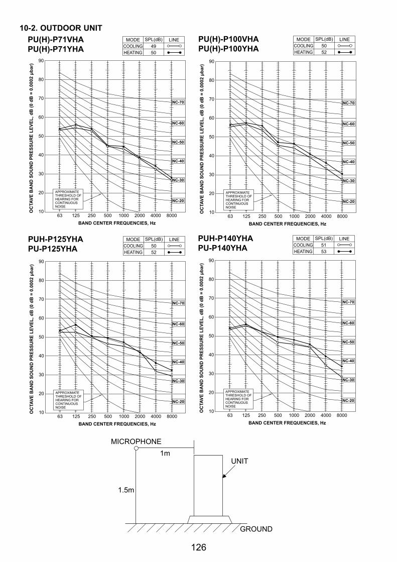
126
90
80
70
60
50
40
30
20
1063 125 250 500 1000 2000 4000 8000
APPROXIMATETHRESHOLD OFHEARING FORCONTINUOUSNOISE
NC-60
NC-50
NC-40
NC-30
NC-20
NC-70
OC
TAVE
BA
ND
SO
UN
D P
RES
SUR
E LE
VEL,
dB
(0 d
B =
0.0
002 μb
ar)
BAND CENTER FREQUENCIES, Hz
PU(H)-P100VHAPU(H)-P100YHA COOLING
MODE
HEATING50
SPL(dB)
52
LINE
90
80
70
60
50
40
30
20
1063 125 250 500 1000 2000 4000 8000
APPROXIMATETHRESHOLD OFHEARING FORCONTINUOUSNOISE
OC
TAVE
BA
ND
SO
UN
D P
RES
SUR
E LE
VEL,
dB
(0 d
B =
0.0
002 μb
ar)
BAND CENTER FREQUENCIES, Hz
NC-60
NC-50
NC-40
NC-30
NC-20
NC-70
PUH-P125YHAPU-P125YHA COOLING
MODE
HEATING50
SPL(dB)
52
LINE
10-2. OUTDOOR UNIT
90
80
70
60
50
40
30
20
1063 125 250 500 1000 2000 4000 8000
NC-60
NC-50
NC-40
NC-30
NC-20
NC-70
OC
TAVE
BA
ND
SO
UN
D P
RES
SUR
E LE
VEL,
dB
(0 d
B =
0.0
002 μb
ar)
BAND CENTER FREQUENCIES, Hz
PU(H)-P71VHAPU(H)-P71YHA COOLING
MODE
HEATING49
SPL(dB)
50
LINE
APPROXIMATETHRESHOLD OFHEARING FORCONTINUOUSNOISE
90
80
70
60
50
40
30
20
1063 125 250 500 1000 2000 4000 8000
APPROXIMATETHRESHOLD OFHEARING FORCONTINUOUSNOISE
OC
TAVE
BA
ND
SO
UN
D P
RES
SUR
E LE
VEL,
dB
(0 d
B =
0.0
002 μb
ar)
BAND CENTER FREQUENCIES, Hz
NC-60
NC-50
NC-40
NC-30
NC-20
NC-70
PUH-P140YHAPU-P140YHA COOLING
MODE
HEATING51
SPL(dB)
53
LINE
1.5m
1mMICROPHONE
UNIT
GROUND
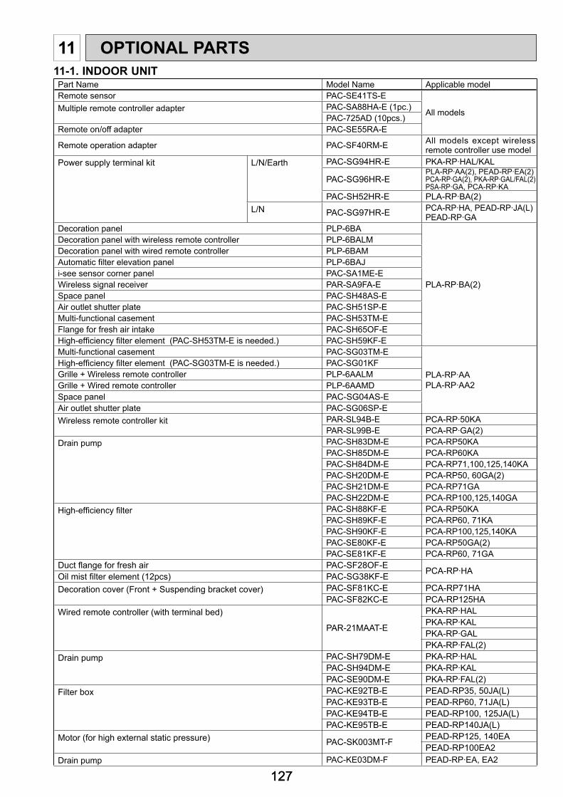
127127
11 OPTIONAL PARTS
Part Name Model Name Applicable modelRemote sensor PAC-SE41TS-E
All models Multiple remote controller adapter PAC-SA88HA-E (1pc.)PAC-725AD (10pcs.)
Remote on/off adapter PAC-SE55RA-E
Remote operation adapter PAC-SF40RM-E All models except wireless remote controller use model
Power supply terminal kit L/N/Earth PAC-SG94HR-E PKA-RP·HAL/KAL
PAC-SG96HR-EPLA-RP·AA(2), PEAD-RP·EA(2)PCA-RP·GA(2), PKA-RP·GAL/FAL(2)PSA-RP·GA, PCA-RP·KA
PAC-SH52HR-E PLA-RP·BA(2)L/N PAC-SG97HR-E PCA-RP·HA, PEAD-RP·JA(L)
PEAD-RP·GADecoration panel PLP-6BA
PLA-RP·BA(2)
Decoration panel with wireless remote controller PLP-6BALMDecoration panel with wired remote controller PLP-6BAMAutomatic fi lter elevation panel PLP-6BAJi-see sensor corner panel PAC-SA1ME-EWireless signal receiver PAR-SA9FA-ESpace panel PAC-SH48AS-EAir outlet shutter plate PAC-SH51SP-EMulti-functional casement PAC-SH53TM-EFlange for fresh air intake PAC-SH65OF-EHigh-effi ciency fi lter element (PAC-SH53TM-E is needed.) PAC-SH59KF-EMulti-functional casement PAC-SG03TM-E
PLA-RP·AAPLA-RP·AA2
High-effi ciency fi lter element (PAC-SG03TM-E is needed.) PAC-SG01KFGrille + Wireless remote controller PLP-6AALMGrille + Wired remote controller PLP-6AAMDSpace panel PAC-SG04AS-EAir outlet shutter plate PAC-SG06SP-EWireless remote controller kit PAR-SL94B-E PCA-RP·50KA
PAR-SL99B-E PCA-RP·GA(2)Drain pump PAC-SH83DM-E PCA-RP50KA
PAC-SH85DM-E PCA-RP60KAPAC-SH84DM-E PCA-RP71,100,125,140KAPAC-SH20DM-E PCA-RP50, 60GA(2)PAC-SH21DM-E PCA-RP71GAPAC-SH22DM-E PCA-RP100,125,140GA
High-effi ciency fi lter PAC-SH88KF-E PCA-RP50KAPAC-SH89KF-E PCA-RP60, 71KAPAC-SH90KF-E PCA-RP100,125,140KAPAC-SE80KF-E PCA-RP50GA(2)PAC-SE81KF-E PCA-RP60, 71GA
Duct fl ange for fresh air PAC-SF28OF-E PCA-RP·HAOil mist fi lter element (12pcs) PAC-SG38KF-EDecoration cover (Front + Suspending bracket cover) PAC-SF81KC-E PCA-RP71HA
PAC-SF82KC-E PCA-RP125HAWired remote controller (with terminal bed)
PAR-21MAAT-E
PKA-RP·HALPKA-RP·KALPKA-RP·GALPKA-RP·FAL(2)
Drain pump PAC-SH79DM-E PKA-RP·HALPAC-SH94DM-E PKA-RP·KALPAC-SE90DM-E PKA-RP·FAL(2)
Filter box PAC-KE92TB-E PEAD-RP35, 50JA(L)PAC-KE93TB-E PEAD-RP60, 71JA(L)PAC-KE94TB-E PEAD-RP100, 125JA(L)PAC-KE95TB-E PEAD-RP140JA(L)
Motor (for high external static pressure) PAC-SK003MT-F PEAD-RP125, 140EAPEAD-RP100EA2
Drain pump PAC-KE03DM-F PEAD-RP·EA, EA2
11-1. INDOOR UNIT

HEAD OFFICE : TOKYO BLDG., 2-7-3, MARUNOUCHI, CHIYODA-KU, TOKYO 100-8310, JAPAN
CCopyright 2006 MITSUBISHI ELECTRIC ENGINEERING CO., LTD.Distributed in Oct. 2009 No.OCS07 REVISED EDITION-D PDF 6Distributed in Apr. 2007 No.OCS07 REVISED EDITION-C PDF 7Distributed in May 2006 No.OCS07 REVISED EDITION-B PDF 8Distributed in Apr. 2006 No.OCS07 REVISED EDITION-A PDF 8Distributed in Mar. 2006 No.OCS07 PDF 8Made in Japan.
New publication, effective Oct. 2009Specifications subject to change without notice.
11-2. OUTOOR UNITPart Name Model Name Applicable modelM-NET adapter PAC-SF81MA-E PU(H)-P71-140A-control service tool PAC-SK52ST PU(H)-P71-140Drain socket PAC-SG61DS-E PU(H)-P71-140Air outlet guide (P125, 140 needs 2 pieces) PAC-SG59SG-E PU(H)-P71-140Air protect guide (P125, 140 needs 2 pieces) PAC-SG57AG-E PU(H)-P71-140Drain pan PAC-SG64DP-E PU(H)-P71-140Filter dryer ([9.52) PAC-SG82DR-E PU(H)-P71-140Distribution pipe (Twin) MSDD-50TR-E PU(H)-P71-140
(Triple) MSDT-111R-E PU(H)-P140Joint pipe (Unit → Extension pipe) ([15.88 → [19.05) PAC-SG75RJ-E PU(H)-P71-140