Embed Size (px)
Citation preview
EN
…no limitsof application!
History…IMET was founded in 1988 and is without doubt one of the pioneering companies in the development and manufacture of radio remote controls. The first prototypes of radio remote control systems appeared on the market by the end of the 1980’s spreading initially in the fields of construction cranes and concrete handling.Within the next few years and as a consequence of the increasing importance of productivity and safety in the industrial and construction fields, the demand of radio remote control systems increased massively and IMET, thanks to the dynamism and high level of technical competence of its staff along with its constant bent towards a technological innovation process, has gained a prominent position on all national and international markets.
Today……IMET can boast a very wide and articulate range of products, able to suit the majority of different requirements inside the industry and construction field and much more. In addition to the standard models, which have been designed for the most traditional application fields, such as construction cranes, bridge cranes and many others, IMET places at the disposal of its customers a staff of technicians, specialised in the design and creation of customised models of radio remote controls, according to the customer’s specific requirements...with no limits of application.
RESEARCH, DEVELOPMENT AND SAFETYIMET radio remote controls have always distinguished themselves with their extreme reliability attained through the use of high quality materials, combined with intense research and extensive product testing. This has resulted in the achievement of safety standards of category 2/PL c and 3/PL d for all movement commands and category 4/PL e for the STOP circuit (EN 954-1/EN 13849).
PRODUCTION
IMET radio remote controls are totally designed and assembled in-house and also subjected to a series of intermediate quality control and final testing, in order to assure quality and reliability. It is this level of hands on control which has enabled IMET to gain the quality mark UNI EN ISO9001: 2000.
Venice
2
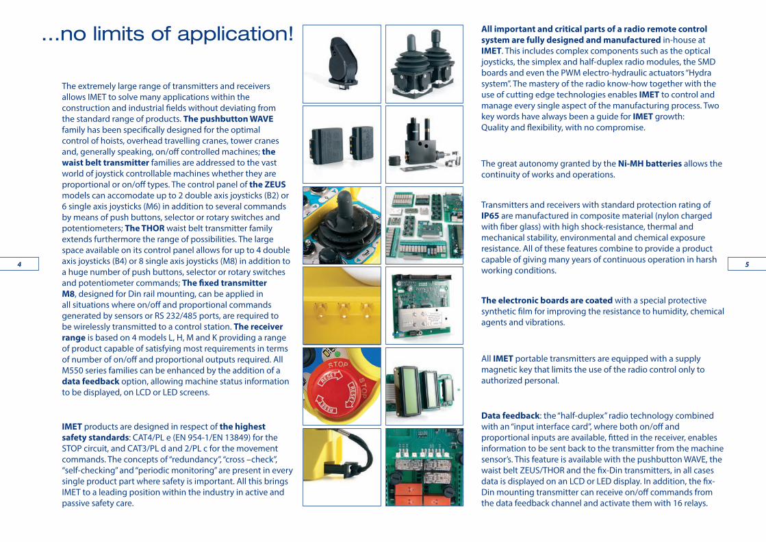
The extremely large range of transmitters and receivers allows IMET to solve many applications within the construction and industrial fields without deviating from the standard range of products. The pushbutton WAVE family has been specifically designed for the optimal control of hoists, overhead travelling cranes, tower cranes and, generally speaking, on/off controlled machines; the waist belt transmitter families are addressed to the vast world of joystick controllable machines whether they are proportional or on/off types. The control panel of the ZEUS models can accomodate up to 2 double axis joysticks (B2) or 6 single axis joysticks (M6) in addition to several commands by means of push buttons, selector or rotary switches and potentiometers; The THOR waist belt transmitter family extends furthermore the range of possibilities. The large space available on its control panel allows for up to 4 double axis joysticks (B4) or 8 single axis joysticks (M8) in addition to a huge number of push buttons, selector or rotary switches and potentiometer commands; The fixed transmitter M8, designed for Din rail mounting, can be applied in all situations where on/off and proportional commands generated by sensors or RS 232/485 ports, are required to be wirelessly transmitted to a control station. The receiver range is based on 4 models L, H, M and K providing a range of product capable of satisfying most requirements in terms of number of on/off and proportional outputs required. All M550 series families can be enhanced by the addition of a data feedback option, allowing machine status information to be displayed, on LCD or LED screens.
IMET products are designed in respect of the highest safety standards: CAT4/PL e (EN 954-1/EN 13849) for the STOP circuit, and CAT3/PL d and 2/PL c for the movement commands. The concepts of “redundancy”, “cross –check”, “self-checking” and “periodic monitoring” are present in every single product part where safety is important. All this brings IMET to a leading position within the industry in active and passive safety care.
All important and critical parts of a radio remote control system are fully designed and manufactured in-house at IMET. This includes complex components such as the optical joysticks, the simplex and half-duplex radio modules, the SMD boards and even the PWM electro-hydraulic actuators “Hydra system”. The mastery of the radio know-how together with the use of cutting edge technologies enables IMET to control and manage every single aspect of the manufacturing process. Two key words have always been a guide for IMET growth: Quality and flexibility, with no compromise.
The great autonomy granted by the Ni-MH batteries allows the continuity of works and operations.
Transmitters and receivers with standard protection rating of IP65 are manufactured in composite material (nylon charged with fiber glass) with high shock-resistance, thermal and mechanical stability, environmental and chemical exposure resistance. All of these features combine to provide a product capable of giving many years of continuous operation in harsh working conditions.
The electronic boards are coated with a special protective synthetic film for improving the resistance to humidity, chemical agents and vibrations.
All IMET portable transmitters are equipped with a supply magnetic key that limits the use of the radio control only to authorized personal.
Data feedback: the “half-duplex” radio technology combined with an “input interface card”, where both on/off and proportional inputs are available, fitted in the receiver, enables information to be sent back to the transmitter from the machine sensor’s. This feature is available with the pushbutton WAVE, the waist belt ZEUS/THOR and the fix-Din transmitters, in all cases data is displayed on an LCD or LED display. In addition, the fix-Din mounting transmitter can receive on/off commands from the data feedback channel and activate them with 16 relays.
…no limits of application!
54

The pushbutton radio type M550 WAVE S range is available with 4, 6 or 8 double-step pushbuttons for the movement commands. In addition, and always present is a Start/Klaxon button and a STOP mushroom-head button. The radio remote also has space for one optional command which can be a multi-position rotary switch, a single-step button or an analogue potentiometer. IMET have paid special attention to the ergonomic design of the WAVE transmitter bearing in mind the practical aspects of compact overall size, large pushbuttons suitable for operations with gloves, easy access and protected STOP button. This make the WAVE S an ideal tool for the control of hoists, overhead cranes and small tower cranes. The possibility of customisation extends the possible uses of this type of transmitter to a large variety of machines equipped with on/off control boxes whether AC or DC powered.
The pushbutton radio M550 WAVE L range is available with either 10 or 12 double-step pushbuttons for the movement commands in addition to the standard Start/Klaxon button and STOP mushroom-head button. The model M550D WAVE L10 can be equipped with a 8+8 digit LCD screen for the displaying of machine status information (using data feedback option). As with the WAVE S, the transmitter has space for an optional command which can be a multi-position rotary switch, a single-step button or an analogue potentiometer. This makes the WAVE L a natural choice for the control of overhead cranes equipped with additional functions such as auxiliary hoist, grabs, magnets, etc. and medium size tower cranes. The possibility of customisation again extends the possible uses of this type of transmitter to a large variety of machines equipped with on/off control boxes whether AC or DC powered.
Dimensions75 x 43 x 180 mm
Weight375 g
Dimensions75 x 43 x 245 mm
Weight445 g
TRANSMITTING UNITM550 WAVE S M550 WAVE L
76

TRANSMITTING UNIT
Dimensions75 x 180 x 43 mm
Weight375 g
Dimensions75 x 180 x 43 mm
Weight375 g
The ARES C is an extremely compact transmitter designed for applications requiring a limited amount of digital and analogue functions operated by toggle switches, pushbuttons, rotary switches and potentiometers such as forestry winches, pumps and many other machinery. ARES C puts great at-tention to the easiness of use, including the situations in which the operator wears gloves, thanks to the well dimensioned command actuators and their rational spacing. For the carrying, the housing is equipped with a robust belt-clip. ARES C features a STOP command in category PLc/CAT2 (ISO 13849:1), SIL1 (IEC 62061) and it can be combined with any of IMET receivers, for delivering on/off, proportional or CAN outputs according to the machine specifications. ARES housing have been designed to operate in the most demanding sectors as indicates the IP65 protection degree.
The ARES E is an extremely compact transmitter designed for applications requiring a limited amount of digital and analogue functions operated by toggle switches, pushbuttons, rotary switches and potentiometers such as forestry winches, concrete pumps, lifting and material handling machines and many others. ARES E puts great attention to the easiness of use, inclu-ding the situations in which the operator wears gloves, thanks to the well dimensioned commands and their rational spacing. For the carrying, the housing is equipped with a robust belt-clip. ARES E features a STOP com-mand in category PLe/CAT4 (ISO 13849:1), SIL3 (IEC 62061) and it can be combined with any of IMET receivers, for delivering on/off, proportional or CAN outputs according to the machine specifications. ARES housing has been designed to operate in the most demanding sectors as indicates the IP65 protection degree.
M550 ARES C M550 ARES E
98

TRANSMITTING UNITM550 ZEUS B2 M550 ZEUS M6The ZEUS B2 transmitter combines the advanced ergonomic design and functional features required in standard application fields such as tower cranes, factory cranes, small concrete pumps, high pressure and vacuum pump vehicles and any other kind of machine for witch double-axis joysticks represent the ideal type of movement command. The ZEUS B2 console has a compact size but nevertheless it reserves ample space for on/off and proportional commands making it an easily customisable transmitter for special applications.
The ZEUS M6 transmitter utilises the same transmitter body as the B2, combined with specially designed proportional joysticks for applications such as hydraulic proportional cranes, telescopic handlers, crawler vehicles and any other kind of machine for witch single-axis joysticks represent the ideal type of movement command. The ZEUS M6 console has a compact size but again, reserves plenty of space for additional on/off and proportional commands making it an easily customisable transmitter for special applications
Dimensions296 X 152 X 147 mm296 X 190 X 147 mm
Weight1450 g
Dimensions212 x 133 x 147 mm212 x 169 x 147 mm
Weight1090 g
1110

TRANSMITTING UNITM550 ZEUS NJThe transmitter ZEUS NJ has been developed for use with high complexity machines where proportional potentiometers, push-buttons and selector switches represent the ideal types of movement commands. The spacious console has room for a large number of commands making ZEUS NJ flexible and customizable for complex AC and DC powered applications.
M550 THOR B3The THOR B3 transmitter has been designed for use with a vast range of complex and high integrity machines, such as, 4-5 booms concrete pumps, full accessory equipped factory cranes, 6 functions hydraulic cranes, special tower cranes, drilling and tunnelling machines. In addition to the 3 double axis joysticks, the extra wide THOR console has capacity for several on/off and proportional commands making it an easily customisable transmitter for special applications whether AC or DC powered.
Dimensions296 X 152 X 147 mm296 X 190 X 147 mm
Weight1450 g
Dimensions212 x 133 x 147 mm212 x 169 x 147 mm
Weight1090 g
1312

M550 THOR M8The THOR M8 transmitter is equipped with up to 8 single-axis joysticks and is specifically designed for machines moved by proportional electro-hydraulic valve banks such as, 7-8 functions hydraulic cranes, crawler lifting machines and other special machines. In addition to the 8 single axis joysticks, the very wide THOR console has room for several on/off and proportional commands making it an easy to customise the system for complex DC powered applications.
M550 THOR B4The THOR B4 transmitter is similar to the B3, but with the addition of a fourth, double axis joystick. This makes it an ideal system for High Integrity factory cranes, 7-8 functions hydraulic cranes, crawler lifting machines and other special machines. In addition to the 4 double axis joysticks, the THOR console has space available for several on/off and proportional commands making it an easily customisable transmitter for special applications whether AC or DC powered.
Dimensions296 X 152 X 147 mm296 X 190 X 147 mm
Weight1450 g
Dimensions296 X 152 X 147 mm296 X 190 X 147 mm
Weight1550 g
1514
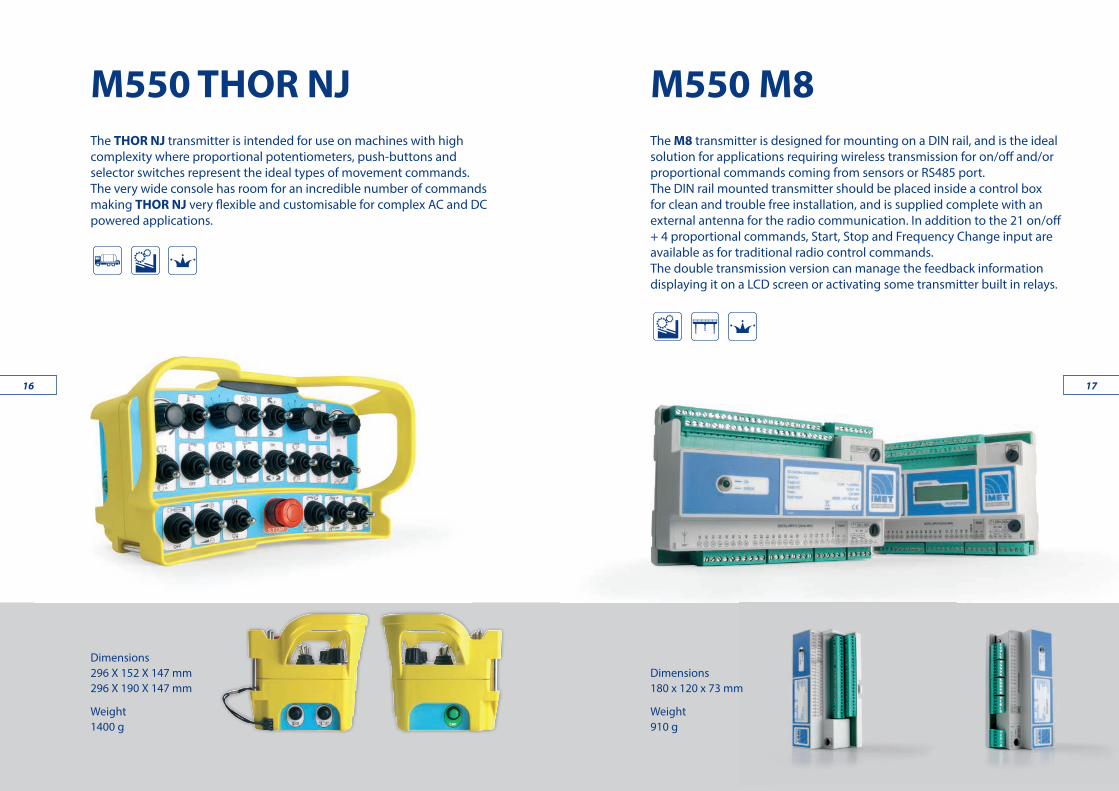
M550 M8
Dimensions180 x 120 x 73 mm
Weight910 g
The M8 transmitter is designed for mounting on a DIN rail, and is the ideal solution for applications requiring wireless transmission for on/off and/or proportional commands coming from sensors or RS485 port. The DIN rail mounted transmitter should be placed inside a control box for clean and trouble free installation, and is supplied complete with an external antenna for the radio communication. In addition to the 21 on/off + 4 proportional commands, Start, Stop and Frequency Change input are available as for traditional radio control commands.The double transmission version can manage the feedback information displaying it on a LCD screen or activating some transmitter built in relays.
M550 THOR NJThe THOR NJ transmitter is intended for use on machines with high complexity where proportional potentiometers, push-buttons and selector switches represent the ideal types of movement commands. The very wide console has room for an incredible number of commands making THOR NJ very flexible and customisable for complex AC and DC powered applications.
Dimensions296 X 152 X 147 mm296 X 190 X 147 mm
Weight1400 g
1716

…NO LIMITS… SAFETY RING IMET introduces an innovative “zone limiter” based on ultrasonic techno-logy. The system creates a 3D ultrasonic zone around the machine by mean of sensors placed in appropriate positions. Colored status led’s built-in the transmitter continuously indicate the operator’s position in relation to that zone. The radio remote control working mode can then be condi-tioned to its position; for example some commands may be active outside the zone and inhibited inside the zone.
GREEN LED ON = the operator is inside the safety ring.
FLASHING GREEN LED = the operator is moving out of the safety ring.
RED LED ON = the operator is outside the safety zone.
1918

ATEX certified Receiving Unit
Group IIElectrical apparatus for other places liable to be endangered by explosive atmospheres. Category 2: High level of protectionComprises products designed to be capable of remaining within their operational parameters in areas in which explosive atmospheres caused by mixtures of air and gases, vapours, mists or air/dust mixtures are likely to occur Protection system against gas and dust Equipment remains energised and functioning in Zones 1, 2 (G) and/or 21, 22 (D) Temperature class 85°C The receiver is completely protected against dust and water jets (IP66); Housing ready for 1” cable guide IOS7/1RC et ¾” IOS7/1RC shield for shielded cable with specification: ATEX Ex II2GD Exd II C IP66; Range, without obstacles, 70m.
Cable control (radio by pass)
ZEUS and THOR units can be equipped with cable control. By plugging in the cable a direct data connection between transmit-ter and receiver is established. The radio transmission is disabled and the power sup-ply of the transmitter is provided through the cable.
Dynamic Speed Control
Dynamic Speed Control introduces an extra control of the proportional functions when operating in “slow speed” mode. DSC+ and DSC- activations adjust the basic settings in order to adapt the machine response to the specific working conditions. DSC is useful especially for those machines equipped with an hydraulic distributor that is not pressure compensated.
DATA FEEDBACK
This option enables the indication of crane or machine information, error messages and warnings on the control panel ensuring a higher level of safety and operating comfort.Graphical displayBacklit, 128X64 pixel resolution, most feedback information available, texts, legends.
Multi Transmitters Receiversconfigurations
This option is the answer for those applications demanding some machines to be shared by several operators through a safe procedure of “loggin-in” and “loggin-out”. In an MTRS system, the receiving units can be logged-in and logged-out by up to 8 different transmitting units. On the other side, each transmitter can operate with up to 16 different receivers. MTRS and MTRS Easy options are available with the complete range of IMET transmitters and receivers.
OPTION…
2120

CERTIFICATIONSIMET achieved along the years many important steps regarding the company certification, quality mark UNI EN ISO 9001 since 1998, and the product certifica-tion, PL e (ISO 13849-1), CAT4 (EN 954-1), SIL3 (IEC 62061).
OPTION…This option ensures that the operator can only start the desired crane. A direc-tional infra red link has to be established between the crane operator and a dedicated receiving device. Only at this point, the radio receiver “Start” command will be authorized.
This dual-axis inclination sensor can be placed inside the transmitting box and interfaced to its logic card in order to implement a “dead man” function. Typically, an inclination of 60° lasting more than 2s, will bring the radio control system to passive emergency status. The angle of intervention is customizable according to the application requests.
High resolution graphics
Thanks to modern printing technologies, IMET is able to customize the lay-out of your consoles delivering high resolution multicolor graphics and legends.
2322
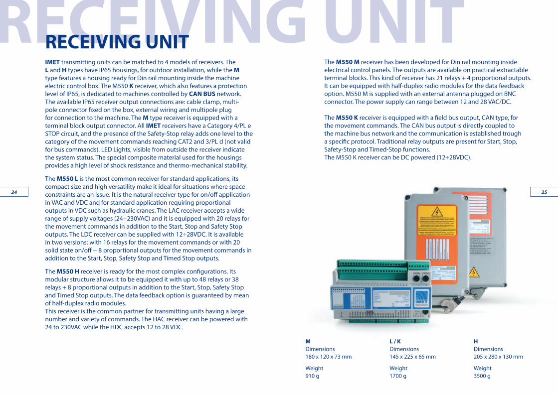
RECEIVING UNITRECEIVING UNITIMET transmitting units can be matched to 4 models of receivers. The L and H types have IP65 housings, for outdoor installation, while the M type features a housing ready for Din rail mounting inside the machine electric control box. The M550 K receiver, which also features a protection level of IP65, is dedicated to machines controlled by CAN BUS network. The available IP65 receiver output connections are: cable clamp, multi-pole connector fixed on the box, external wiring and multipole plug for connection to the machine. The M type receiver is equipped with a terminal block output connector. All IMET receivers have a Category 4/PL e STOP circuit, and the presence of the Safety-Stop relay adds one level to the category of the movement commands reaching CAT2 and 3/PL d (not valid for bus commands). LED Lights, visible from outside the receiver indicate the system status. The special composite material used for the housings provides a high level of shock resistance and thermo-mechanical stability.
The M550 L is the most common receiver for standard applications, its compact size and high versatility make it ideal for situations where space constraints are an issue. It is the natural receiver type for on/off application in VAC and VDC and for standard application requiring proportional outputs in VDC such as hydraulic cranes. The LAC receiver accepts a wide range of supply voltages (24÷230VAC) and it is equipped with 20 relays for the movement commands in addition to the Start, Stop and Safety Stop outputs. The LDC receiver can be supplied with 12÷28VDC. It is available in two versions: with 16 relays for the movement commands or with 20 solid state on/off + 8 proportional outputs for the movement commands in addition to the Start, Stop, Safety Stop and Timed Stop outputs.
The M550 H receiver is ready for the most complex configurations. Its modular structure allows it to be equipped it with up to 48 relays or 38 relays + 8 proportional outputs in addition to the Start, Stop, Safety Stop and Timed Stop outputs. The data feedback option is guaranteed by mean of half-duplex radio modules. This receiver is the common partner for transmitting units having a large number and variety of commands. The HAC receiver can be powered with 24 to 230VAC while the HDC accepts 12 to 28 VDC.
The M550 M receiver has been developed for Din rail mounting inside electrical control panels. The outputs are available on practical extractable terminal blocks. This kind of receiver has 21 relays + 4 proportional outputs. It can be equipped with half-duplex radio modules for the data feedback option. M550 M is supplied with an external antenna plugged on BNC connector. The power supply can range between 12 and 28 VAC/DC.
The M550 K receiver is equipped with a field bus output, CAN type, for the movement commands. The CAN bus output is directly coupled to the machine bus network and the communication is established trough a specific protocol. Traditional relay outputs are present for Start, Stop, Safety-Stop and Timed-Stop functions. The M550 K receiver can be DC powered (12÷28VDC).
MDimensions180 x 120 x 73 mm
Weight910 g
HDimensions205 x 280 x 130 mm
Weight3500 g
L / KDimensions145 x 225 x 65 mm
Weight1700 g
2524

A-W-Z-T MT-Z A-W-M
A= M= W= Z= T=
TECHNICAL INFORMATIONWorking frequencyReference normsChannel spacingNumber of P.L.L. programmable radio channels Range ModulationEmission power of the R.F. systemRF receiver type Receiver sensibilityEmission class
Error non-detection probabilityDelay time on receiver start
I.S.M Band 434.050 ÷ 434.775 MHzETSI EN 300 220-3 V 1.1.1
25 KHz Simplex, (25 KHz Half Duplex)*30
100 mGMSK
10 mW ERP (Antenna Interna)Supertherodine IF 83.16 MHz - 455 KHz*
0,22µV per 12 dB Sinad25K0F1D
9< 7.34 x 10⁻¹²
Hamming distance
Response time of commandsResponse time of active emergencyResponse time of passive emergencySafety category of STOP command
< 3 s
< 750 ms< 110 ms, < 120 ms*< 150 ms, < 220 ms
< 800 ms
Delay time on the start command
Safety category of movement commands
Operation and storage temperatureYES
Available pairing addresses 65536
Safety category of datafeedback commands
Datafeedback ready-20 ÷ +70°C, (-4 ÷ 158°F)
General data
Analogue output with loop of current
PWM analogue outputMax. quantity of analogue commandMax. quantity of ON/OFF command (NO)Safety commands
Analogue output in tension
Analogue output in tension Housing protection degreeHousing material Datafeedback ready
Input ports*
Max quantity of digital inputs*Max. quantity of analogue inputs*Supply tension VacSupply tension VdcPower demand
Service commands Start, T-Stop, Horn, Blink
Start, (Horn, T-Stop)***
Start, Horn,Blink
Safety-stop, Stop Safety-stop, Stop Safety-stop, Stop48 20 21
0 ÷ 1,4 A max 0 ÷ 1,4 A max /
0 ÷ 20 mA4 ÷ 20 mA
0 ÷ 20 mA4 ÷ 20 mA
0 ÷ 20 mA4 ÷ 20 mA
min 25% Vccmed 50% Vcc max 75% Vcc
min 25% Vccmed 50% Vcc max 75% Vcc
min 25% Vccmed 50% Vcc max 75% Vcc
0 ÷ (Vcc-3) reg. 0 ÷ (Vcc-3) reg. 0 ÷ (Vcc-3) reg.IP65 IP65 /
charged Nylon charged Nylon ABSYES YES YES
Serial, parallel
CAN, Serial, parallel
Serial, parallel
8 8 114 4 4
24, 48, 55, 110, 230 24, 48÷55, 110, 230 12 min - 28 max12 min - 28 max 12 min - 28 max 12 min - 28 max
20 W max 15 W max 15 W max
M550 H M550 L / K M550 MReceiving Unit
8 8 4
Battery charger CB5000 Wave CB3600 Zeus / Thor
Supply tension 12 min - 32 max Vdc(optional 230 Vac)
12 min - 32 max Vdc(optional 230 Vac)
Power demand 250mA DC, 35mA AC, (while charging)
250mA DC, 35mA AC, (while charging)
Charging current 550mA 600mAMax. charging time 3 hours 3 hoursCharge type PVD PVDHousing protection degree IP30 IP30
+5 ÷ + 45°C (+41 ÷ +113°F)
+5 ÷ + 45°C (+41 ÷ +113°F)Storage temperature with loaded battery
Storage temperature off and without battery -20 ÷ +70°C (-4 ÷ +158°F)
-20 ÷ +70°C (-4 ÷ +158°F)
Dimensions (L.P.H.) 75x49x142 mm 75x49x156 mmWeight 250g 251gWeight with 230Vac transformer (optional) 490g 491g
Transmitting unit M8 Transmitting unit Wave
Transmitting unit Zeus Transmitting unit Thor
Transmitting unit Ares E * Datafeedback version** Only for data acquisition*** DC
Housing material Housing protection degreeService and Safety commandsMax. quantity on analogue commands Max. quantity of ON/OFF undirect commands
Supply tension
Current demandPower demandBattery
Autonomy at 20 °C with charged battery continuos operation
Advice time “battery down”
LCD Display (optional)
Visualisation speed for the ch. on the display*Max. quantity of command relays (NO)
Max. quantity of ON/OFF direct commands
4 (Start, Klaxon, Gyroph., Stop)
Transmitting Unit32 16 S - 24 L - 20 L* 32 1648 48 48 488 1 8 3
1 (Klaxon)/ IP65 IP65 IP65
ABS charged Nylon charged Nylon charged Nylon
12 min - 28 max Vac/Vdc 2,4 Vdc
/
3,6 Vdc
/
3,6 Vdc
/
240mA-260mA* 100mA-120mA* 160mA - 180mA* 0,80mA1,4 W - 1,5 W* 0,3 W 0,58 W - 0,65 W* 0,25W
/ NiMh 2,4V-1,5A/h NiMh 3,6V-1,7A/h NiMh 3,6V-1,8A/h
/ ≃ 18 ore, ≃ 15 ore*
≃ 12 ore, ≃ 10 ore* ≃ 22 ore
/ ≃ 15 min ≃ 15 min ≃ 15 min
2 lines 16 ch./
2 lines 8 ch./
2 lines 16 ch.4 lines 20 ch. /
100 char/s 100 char/s 100 char/s /16*
6A / 110V AC16A / 28V DC1
/ / /
M8 Wave S-L Zeus-Thor Ares C / E
Max. carrying capacity of command relays
PLe cat.4/SIL3 (ISO 13849-1/EN 62061) / PLd cat. 3/SIL 2 (ISO 13849-1/EN 62061) PLd cat. 3/SIL 2 (ISO 13849-1/EN 62061) / PLc cat.2 /SIL 1(ISO 13849-1/EN 62061)
PLc cat. 1 / SIL 1 (ISO 13849-1/EN 62061)
2726

PT
P
T
1
HYDRAULIC ACTUATORHYDRAULIC ACTUATORThe “PWM Hydra system” combining electro hydraulic-actuators, with either ZEUS and THOR radio remote controls, allows the conversion of hydraulic manual cranes into radio controlled ones.The actuator hydraulic circuit is totally independent from the crane hydraulics, hence avoiding oil-sharing problems that can arise due to the presence of dirt in the crane oil compromising the regular working of the actuator pistons.The power pack works only “on demand”, when movements are operated from the transmitter, granting low stress conditions and reducing all energy wastes. The calibration of every single actuator can be performed via radio directly from the transmitter. The Hydra system kit is comprehensive, and consists of: block of actuators, power pack, wiring between receiver/actuators/power pack, rod clamps, hydraulic pipes.
Electrohydraulic Power PackAbsorption by 27 VdcAbsorption by 13,5 VdcSupply tensionWorking pressureWorking room temperatureTank capacityConnectors of the hydraulic circuitDimensions (L. P. H.)Dry weight
Hydraulic ActuatorPilot systemCoil resistance by 20°C (68°F)Absorption by 27 VdcAbsorption by 13,5 VdcOperating room temperature
Max. stroke optionalThrust and traction force by 12 barOptimum operation pressureMax. available operation pressureConnectors of hydraulic circuitDimensions (L. P. H.)Weight (single module)Standard interaxeStandard functions
4,5A
PWM a 80Hz5,5 Ohm170 ÷ 620 mA300 ÷ 1250 mA-20°C ÷ +70°C (-4°F ÷ 158°F)
40 mm (±20mm from the centre)600N15 ÷ 20 bar30 bar1/4“ Gas210 x 38 x 138 mm1500 g38, 42, 44, 46, 48, 50 mm4 ÷ 8
9A12 o 24 Vdc +20% -10%18 bar 27 Vdc - 16 bar 13,5 Vdc -20°C ÷ +70°C (-4°F ÷ 158°F)0,5 litres1/4“ Gas305 x 120 x 160 mm4850 g
Max. stroke 26 mm (±13mm from the centre)
CRANE ROD
PUMP
PT
P
T
1
ACTUACTOR
COMMANDACTUACTOR CONNECTOR
COMMANDACTUACTOR CONNECTOR
ANCHORINGCLAMP
CRANE ROD
UNIT PACKSUPPLY
CONNECTORMOTOR
ELECTRONICCONTROL
DISTRIBUTOR
BY-PASSELECTRO-VALVE
PUMP
DRAIN PIPE
OIL FILTER
PWM Hydra systemoptional
2928
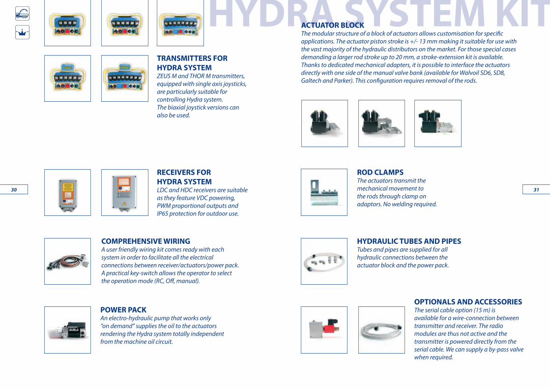
HYDRA SYSTEM KIT TRANSMITTERS FOR HYDRA SYSTEMZEUS M and THOR M transmitters, equipped with single axis joysticks, are particularly suitable for controlling Hydra system. The biaxial joystick versions can also be used.
RECEIVERS FOR HYDRA SYSTEMLDC and HDC receivers are suitable as they feature VDC powering, PWM proportional outputs and IP65 protection for outdoor use.
COMPREHENSIVE WIRINGA user friendly wiring kit comes ready with each system in order to facilitate all the electrical connections between receiver/actuators/power pack. A practical key-switch allows the operator to select the operation mode (RC, Off, manual).
ROD CLAMPSThe actuators transmit the mechanical movement to the rods through clamp on adaptors. No welding required.
HYDRAULIC TUBES AND PIPESTubes and pipes are supplied for all hydraulic connections between the actuator block and the power pack.
OPTIONALS AND ACCESSORIESThe serial cable option (15 m) is available for a wire-connection between transmitter and receiver. The radio modules are thus not active and the transmitter is powered directly from the serial cable. We can supply a by-pass valve when required.
POWER PACKAn electro-hydraulic pump that works only “on demand” supplies the oil to the actuators rendering the Hydra system totally independent from the machine oil circuit.
ACTUATOR BLOCK The modular structure of a block of actuators allows customisation for specific applications. The actuator piston stroke is +/- 13 mm making it suitable for use with the vast majority of the hydraulic distributors on the market. For those special cases demanding a larger rod stroke up to 20 mm, a stroke-extension kit is available. Thanks to dedicated mechanical adapters, it is possible to interface the actuators directly with one side of the manual valve bank (available for Walvoil SD6, SD8, Galtech and Parker). This configuration requires removal of the rods.
3130
251988 - 2013
Org
anis
mo
accr
edit
ato
da A
CCRE
DIA
Body
acc
redi
ted
by A
CCRE
DIA
SISTEMA DI GESTIONE CERTIFICATO
REG. N. 457-AUNI EN ISO 9001:2008
IMET s.r.l. - Via Fornace, 8 33077 Sacile (PN) Italy
Tel. +39 0434 7878 Fax +39 0434 737848
www.imet.eu - [email protected]
CAT0
1-01
.15
EN
IMET Srl reserves the right to make eventual changes to the product without notice.

![Service Redundancy Protocol Configuration Mode Commands · noadvertise-routes-in-standby-state[hold-off-time][reset-bfd-nbrs] default Setsthespecifiedrouteadvertisementoptiontoitsdefaultvalue–:](https://img.pdfslide.us/doc/110x75/5bfe16b109d3f2740f8cb075/service-redundancy-protocol-configuration-mode-commands-noadvertise-routes-in-standby-statehold-off-timereset-bfd-nbrs.jpg)