Embed Size (px)
Citation preview

I.lANUFAC:TURED BY WELDING I NDUSTRI EE; OF ACISTRALI A LTD.
HEAD OFFICE AND EXPORT D I U I S I O N T e l e p h o n e 8 3 465-251 1 2-28 A u s t a r c A v e n u e , T h c l m a s t c l w r l , F a c s i m i 1 e 83 465-8612 U i c . 3 0 7 4 , A u s t r a l i a T e l ex .AA32493 AUSTARC
EQU I PMENT tIANIIFACTUFt I NG D I U I S I ON T ~ r l e p h u n e 88 2?6-64F'4 112 Daws Road, E d w a r d s t o w n F a c s i r n i 1 e 68 2 7 6 - 8 3 0 3 S , A . 5839, k u c . t r a 1 ia T e l e x AA82856 AUSTAHC
SALES AND SERVICE BRANCHES A d e l a i d e p h 0 8 276 6888 t 1 x AA82856 f a x G18 276 6327 B r i s b a n e p h 0 7 8 4 4 1391 f a x 07 8 4 4 6228 L a u n c r s t o n p h 8 8 3 4 4 7822 f a x 0 8 3 4 4 6679
WELDMATIC WIRE FEEDER
MODEL NO. W18
C A T . 12/88
M a c k a y p h 87P 51 3532 f a x 8 7 P 51 3175 Ple1bour r i e ph 63 425' 4766 t l X AA32493 f a x 63 427 9267 N e w c a s t l e p h 049 61 l668 t l x A A 2 4 1 5 5 f a x 649 62 29P2
S y d n e y p h 0 2 6 4 7 2655 t l x A A 2 4 1 5 5 f a x 8 2 7 4 8 3818 Wol 1 clrlgclnq p h 842 7 1 81 I 1 f a x G142 71 8889
P e r t h p h 09 361 7888 f a x BP 470 3538
THE INFORMATION CONTAINED I N THE FOLDER IS SET OUT TO ENABLE YOU TO
MAXIMUM OPERATING EFFICIENCY. PROPERLY M A I N T A I N YOUR NEW EQUIPMENT AND ENSURE THAT YOU OBTAIN
PLEASE ENSURE THAT THIS FOLDER IS KEPT I N A SAFE PLACE FOR READY REFERENCE WHEN REQUIRED.
WHEN REQUESTING SPARE PARTS, QUOTE THE MODEL NO. AND SERIAL N O . OF THE MACHINE AND PART N O . OF THE ITEM REQUIRED. FAILURE TO SUPPLY T H I S INFORMATION MAY RESULT I N UNNECESSARY DELAYS I N SUPPLYING THE CORRECT PARTS.
-SAFETY-
B e f o r e t h i s e q u i p m e n t i s p u t i n t o o p e r a t i o n , the SAFETY PRACTICES s e c t i o n a t the b a c k of t h e M a n u a l MUST BE READ COMPLETELY. T h i s w i l l h e l p auc l id p o s s . i t , l e i n j u r y due t o m i s u s e o r improper w e l d i n g a p p l i c a t i o n s .

WELDMATIC W1 8 W 1 RE FEEDER MANUAL PAGE 2
C ONT ENT S
SECT I ON PAGE
F I GURE PAGE
1 . C o n t r o l s . . . . , , . . , , , , , . , , . 3 2 . \ d i r e Feeder C i r c u i t Diagram . . . , . . , 8 3. W16-20 Wire F e e d B o a r d , , , . . , . . . . l 1 4 . IJi6-21 Wire F e e d B o a r d . . . . . , . , . . l 5 5. WI 8 Wire F e e d e r Asserrltti y . . . . . . . . 15 6 . W19 F o u r Rol 1 D r i v e AsSembl). . . . , . .17 7 . Speed Change Gear T a b l e . . . . , . . . - 1 8 3. Drive R o l l & Wire G u i d e T a b l e . . , . . l 8 P . S p o o l H o l der A E . s e m t l l ies . . . . . , , . . , 19
1 0 . A c c e s s ~ r r L e a d K i t s . , . , . . . . . , .28
T h e W . I . A . W18 t y p e w i r e feeder h a s . beer1 des igned t o f e e d a range of h a r d , s a f t a n d f l u x c o r e d w i r e s for t h e G a s - M e t a l A r c Welding p r u c e s ~ . . A l o w i n e r t i a , P r i n t e d C i r c u i t t y p e motclr w i t h i n t e g r a l s p u r gear box is; c o u p l e d t o a four r o l l d r i v e a s s e m b l y f o r m i n g t h e basic c o r n p u n e n t o f t h e wire f e e d e r , T h e m o t o r i E. c o n t r o l 1 ed by a n e l e c t r o n i c s p e e d con t r a1 w h i c h e n s u r e s e x c e l l e n t s p e e d r e g u l a t i o n over t h e f u l 1 t o y q . u e range o f the motc t r , a n d i n h e r e n t c c m p e n s a t i o n f o r s u p p l y v01 tage v a r i a t i o n s .
F o l l o w i n g d e l i v e r y o f t h e e q u i p m e n t , c h e c k goods r e c e i v e d ag&inst t h e W . 1 . A . i n v o i c e , a n d d e t e r m i n e t h a t t h e d e l i v e r y is c o m p l e t e and undamaged. Any c l a i r n ~ . f o r 1055es clr damage rrrust be f i l e d by t h e Purchaser w i t h W e l d i n g I n d u s t r i e s of A u s t r a l i a P t r . L t d . or t h e i r a u t h o r i z e d a g e n t irrlmediately ( r e f e r t o e q u i p m e n t warranty card a t t h e rea r a f t h i s m a n u a l ) .

CONTROLS
The c c m t r o l s f o r a s tandard Model W 1 1 a r e as a p p e a r s h e l o w . ( I n the i n s t a n c e o f a f a c t o r y f i t t e d o p t i o n p a n e l see a l s o a p p e n d i x a t t h e rear o f t h i c. manual ,
Power o n I n d i c a t o r
Power Switch Inch/Purge Switch
F1 GURE 1 . CONTROLS
WIRE SPEED CONTROL - S e t s t h e speed o f t h e wire d r i v e matar w i t h i n t h e s p e c i f i e d range o f B - 130 r .p .m. , e q u i u a l e n t t u 0 - 16 metres per m i n u t e o f w e l d i n g e l ec t rode w i r e . Rotate t h e c o n t r o l . c l o c k w i s e to increase the f e e d r a t e .
POWER ON INDICATOR - When i l l u m i n a t e d , shows s u p p l y i s c o n n e c t e d t o *
swi t c h e d on.
to c o n n e c t ctr d i s c o r l r l e c t t h e u n i t frorrr 36 u . a . c .
t h e u n i t , a n d i t is
POWER SWITCH - Use E ; u p p l r .
INCH/PURGE SWITCH e n e r g i s e t he gas ua ga0 1 i n e s .
- F r o m t h e c e n t r a l s w i t c h p o s i t i o n , 1 i f t t u lue i n order t o set the gas f l o w r a t e , a n d p u r g e
Deprerss t h e s w i t c h t o r u n the wire drive motor, w i t h o u t energizing t h e w e l d i n g p o w e r s o u r c e c o n t a c t o r .

INSTALLATION
t L- + -
(To work piece)
Gas to Gun
Gas Supply to Wire Feeder
B o t h electrical and shielding gas c o n n e c t i o n s . t o the Wire Feeder are represented in the diagram abclue. Check all connections a r e firmly made to ensure positive electrical contact, and eliminate gas and air l e a k s . The positive welding lead is at tached t o the side of the four-rol 1 drive u n i t , using t h e 3/8"W s e t - s c r e w prouided.
Check tha t the w i re guide and d r i v e rollers f i t t e d are appropriate to t h e e ? e c t r o d e wire t o be used. For t h e recommended combinations, see diagram page 18. Standard units a r e f a c t o r y f i t t e d w i t h W2-22 b c l t t m p o l lerc,, and tJ2-28 t o y rollers, which are sui table f o r both 0 . 9 and 1.2mm diameter steel wire.

WELDPlC?tTl C: W1 8 W 1 RE FEE@EF: IIANUAL PAGE S
F I T T I N G SWIVEL MOUNT
c\ s t a n d a r d WELDPlATI C p a c k a g e w i 1 l i n c 1 ude a w i r e feeder c.wive1 mount k i t At4111 ~ ~ ~ 1 p r i 5 i n g a n k M 1 1 1 / 1 s o c k e t , and a W14-16 5 w i ~ e l p i n . To t ' i t t h e s e i terns. -
( 1 ) U n s c r e w the e y e - n u t f r c m the t o p o f the w e l d i n g F I C I W ~ ~
s o u r c e , a n d r e p l a c e i t with t h e AM11 s o c k e t . T i g h t e n , u s i n g a sma.1 1 tlar t h r u u g h t h e 7mm hcll e i n the s u c k e t .
( 2 ) I n v e r t t h e wi re f e e d e r t o f i t the W14 s w i v e l p i n . T h e p i n . a n d b r a c k e t i s c . ecured t o the wire f e e d e r u c . i n q the 4 o f f 1 /4 " W h i t . a n d 1 o f f 3/8" W h i t . 5et screws s u p p l i e d , t h r o u g h t h e p1.e punched holes . i n the wire f e e d e r c . h e e t metal . Nclte tha t the p i n is o f f s e t on t h e m o u n t i n g b r a c k e t , a n d w i l l o n l y f i t c o r r e c t l y one way. S e c u r e a1 1 f a c . t e n i n q s f i r m l y .
(3) F i t the f i t l r e t h r u s t washer clrltcl the s w i v e l p i n , then 1 ower t h e a s s e m b l y o n t o the Al l1 I 1 s o c k e t .
Fo l lowing Cor rec t i nc . t a1 1a t i c l r - l o f the Wire Feeder , apFt1). pc lwer t u t h e u n i t and check t h e f o l l o w i n g f u n c t i o n s .
- Off /On - Gas Purge - Wi re I n c t-1 - G u n S w i t c h O p e r a t i o n
CIPERAT I ON
lcl f e e d wi re t h r o u g h t h e gun catale cclndui t , f i r s t c a r e f u l l y s t r a i g h t e n the f r e e end o f t h e e l e c t r o d e w i r e , t h e n c u t i t i n t h e c e n t r e of the s t " r + i g h t e n e d s e c t i o n , Wi t h the top f e e d r o l 1 g a t e a s s e m b l y open, 'pass the e l e c t r o d e w i r e end t h r o u g h the i n p u t w i r e g u i d e , o v e r t h e t l o t t o m d r i u e r u l 1er g r o c ~ ~ e . T h e t o p f e e d r c l l l g a t e a s s e m b l y c a n now b e l o w e r e d i n t o p o s i t i o n , a n d t h e c o m p r e s s i o n s c r e w e n g a g e d . N o t e ! Corr~pres~. the s p r i n g w i t h s u f f i c i e n t f o r c e o n l y t o p r o v i d e p o s i t i v e w i r e f e e d . E x c e s s i v e pressure between t h e d r i v e r o l l e r s w i l l r e c . u l t i n d e f o r m a t i o n o f the e l e c t r o d e wire , a n d w i l l a c t a g a i n s t s m o o t h wire f e e d i n g .
U s i n g the 'Wire I n c h ' s w i t c h , a d v a n c e the w i r e down the gun c a b l e a n d o u t of the w e l d i n g t i p , C u t the w i r e a p p r o x i m a t e l y lOmm f r o m the we1 d i rig t i p
F o r i n f o r r n a t i m r e g a r d i n g weld s e t t i n g s . , g a s f l o w r a t e s e t c . ccsrlsul t t h e W e l d i n g Power S o u r c e m a n u a l ,
NOTE! When t h e W e l d i n g P o w e r S a u r c e c c m t a c t o r i s e n e r g i s e d , t h e f o u r r o l l d r i v e a n d t h e w i re spool a r e 1 i u e ( a t t h e w e l d i n g p o t e n t i a l ) wi t h r e s p e c t t o the w o r k 1 e a d .
MAINTENANCE
T h e w i r e f e e d e r s h o u l d require l i t t l e m a i n t e n a n c e o ther than the r e g u l a r ' b l o w i n g o u t ' o f a n y a c c u m u l a t e d d u s t i n o r d e r t o ensure the e f f i c i e n t c a u l i n g of the e l e c t r o n i c c o ~ ~ ~ p o n e n t s . The wire d r i u e motor gearbox is l u b r i c a t e d w i t h 8. long 1 i f e g r e a s e , a n d w i l l no t n o r m a l I Y r e q u i r e a n y m a i n t e n a n c e p r o c e d u r e .
To gain a c c e s s t o t h e e l e c t r o n i c c a n t r o l s o f t h e w i r e f e e d e r , remove t h e two 3/16" muc,hrom h e a d s c r e w s f r o m t h e t o p f r o n t o f t h e u n i t , a n d h i n g e t h e l i d u p w a r d s .
MELD~IAT I c: WI I W I RE FEEDER t l A r w x PAGE A
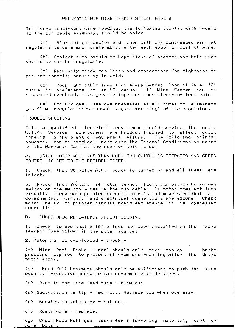
To e n s u r e c o n s i s t e n t w i r e f e e d i n g , t h e f o l l o w i n g p o i n t s , w i t h r e g a r d t u t h e gun c a t l l e ac,.E.emtlly, s.hctu1d be n o t e d .
<a> Blow ou t gun cab les and 1 i n e r w i t h d r y c o m p r e s s e d a i r a t r e g u l a r i n t e r v a l : . a n d , p r e f e r a t l l y , a f t e r e a c h s p o o l or c o i l ctf w i r e .
( b l C o n t a c t t i p s s h o u l d be k e p t c l e a r o f s p a t t e r a n d h o l e s i z e s.hclu1d be c h e c k e d r e g u l a r l y .
C c > R e g u l a r l y c h e c k g a ~ . l i n e s a n d c c t r t r l e c t i u n s f o r t i g t 1 t n e s . s t o p r e v e n t p o r o s i t y o c c u r r i n g i n w e l d .
( d ) Keep gun ca t l le f r e e f r o m E.har.p tends; lc top i t i n ic " C : " c u r v e i n p r e f e r e n c e t o an " S " c u r v e . If Wi re Feeder can be s u s p e n d e d o v e r h e a d 7 t h i s g r e a t l y i m p r o v e s c o n s . i E . t e n c y of f e e d r a t e .
(e> For C O 2 gas, u s e gas p r e h e a t e r a t all t i m e s t o e l i m i n a t e gas. f l o w i r r e g u l a r i t i e s c a u s e d b y gac. " f r e e z i n g " o f t h e r e g u l a t o r .
TROUBLE SHOClTI N G
O n l y d q u a l i f i e d e l e c t r i c a l s e r v i c e m a n c . h o u l d s e r v i c e t h e u n i t , W. I .A . S e r v i c e T e c h n i c i a n s a r e P r o d u c t T r a i n e d t o e f f e c t q u i c k r.epair.5. i n t h e e v e n t o f e q u i p m e n t f a i 1 u r . e . T h e f o l l o w i n g p o i n t s . , however , can be checked - n o t e a l s o t h e G e n e r a l C o n d i t i o n s as n o t e d cm t h e W a r r a n t y Card a t t h e r e a r o f t h i 5 manual . A . D R I V E MOTCjf? WILL NOT TURN WHEN GUN SWITCH IS OPERATED AND SPEED CONTROL IS SET TO THE DESIRED SPEED.
1 . Check t h a t 3 0 oo1 t s A . C . power i s t u r n e d on a n d all f u s e s a r e i n t a c t . 2 . press Irrct-1 S w i t c t l , i f m o t c ~ r . t u r n s , +au l t c a n either. be in g u n s w i t c h or t h e s w i t c h wire5 i n t h e gun cab le . I f m o t o r d o e s n o t t u r n v i s u a l Ir c h e c k h o t h p r i n t e d c i r c u i t t m a r d ' s . a n d make w r e t h a t a1 1 c a m p o n e n t r y , w i r i n g , a n d e l e c t r i c a l c o n n e c t i o n s are secure. Check motor r e l a y ctn p r i n t e d c i r c u i t t t c e r d a n d e n s u r e i t i c . o p e r a t i n g c o r r e c t l y .
B. FUSES BLOW REPEATEDLY WHILST WELDING
1 . C h e c k t o see t h a t a lbAmp f u s e has been i n s t a l l e d i n t h e " w i r e f e e d e r " f u s e h o l d e r i n the power suurce'.
2. Motor m a y b e o v e r l o a d e d - check : -
(a) Wire Reel B r a k e - r e e l s h o u l d o n l y haue enough b rake p r e s s u r e a p p l i e d t o p r e v e n t i t from o v e r - r u n n i n g a f t e r t h e d r i v e mlotor 5 t U P S .
( h > Feed R o l l P r e s s u r e s h o u l d o n l y be s u f f i c i e n t tc t push t he w i r e e v e n l y . E x c e s s i v e p r e s s u r e c a n d e f o r m e l e c t r o d e w i r e s .
Cc) D i r t i n t h e w i r e f e e d t u b e - b l o w o u t .
( d > O b s t r u c t i o n i n t i p - r e a m o u t . R e p l a c e t i p when o v e r s i z e .
(e> B u c k l e s i n w e l d w i r e - c u t o u t .
( f > Rusty w i r e - r e p l a c e ,
(g) Check Feed R o l l g e a r t e e t h f o r i n t e r f e r i n g r r r a t e r i a l , d i r t o r
WELDlIATI C W1 b W 1 HE FEEDER MANUAL PAGE 7
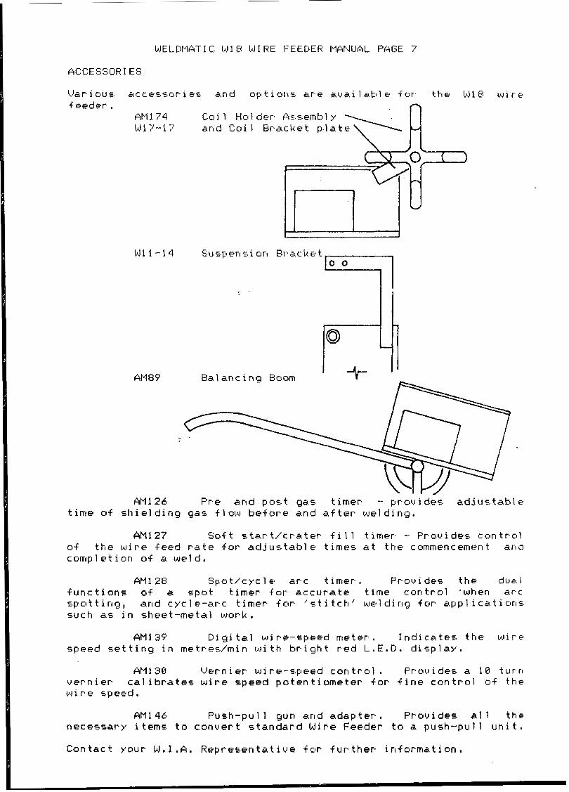
ACCESSORIES
AM84 Bal anc i ng Boom ",:
AM1 27 Soft e t a r t l c r a t e r f i l l timer - Pruvidae. c c l n t r o l of the wire f e e d r a t e for a d j u s t a b l e t imes a t t h e c o m m e n c e m e n t ana c u r r l p l e t i o n o f a we1 d .
AM1 28 S p o t / c y c l e a r c t imer. Prauides t h e d u a l f u n c t i o n s o f a 5 p o t timer f o r a c c u r a t e t ime c o n t r o l ' w h e n a r c c , p o t t i n g , a n d c y c l e - a r c t i m e r for ' s t i t c h ' w e l d i n g fur a p p l i c a t i o r r s s u c h as i n s h e e t - m e t a l w o r k ,
A M I 39 Diyi tal w i r e - s p e e d m e t e r . I n d i c a t e s t h e w i r e s p e e d s e t t i n g i n m e t r e d r n i n w i t h b r i g h t r e d L .E .D . d i s p l a y .
AM1 30 V e r n i e r wire-speed c o n t r o l . Prowides a 18 t u r n v e r n i e r c a l i b r a t e s w i r e speed p o t e n t i o m e t e r f a r f i n e c o n t r o l of t h e w i r e s p e e d .
AM1 46 P u s h - p u l l g u n a n d a d a p t e r . P r o v i d e s a l l t h e n e c e s s a r y items t o c o n v e r t s t a n d a r d W i r e Feeder t o a p u d i - p u l l u n i t .
C o n t a c t y o u r W . 1 . A . R e p r e s e n t a t i v e f o r f u r t h e r i n f o r m a t i o n .

WELDMATIC W18 WIRE FEEDER MANUAL PAGE 8
1
FIGURE 2. WIRE FEEDER C I R C U I T DIAGRAM I ~~

WELDMATIC W1 b W 1 RE FEEDER kI/;NUAL PAGE 9
SEQUENCE OF EVENTS ( r e f e r C i r c u i t W 1 7 - C 3 )
When t h e M i r e F e e d e r i s e n e r g i s e d , a 38U f u l l wave r e c t i f i e d s u p p l y u u l t a g e e x i s t s a t the cathcades o f D 5 and D 6 .
Zener Diodes 2 1 and 2 2 deve lop 12U and:, 24U D . C . f i l t e r e d s u p p l i e s . The 1 i q h t e m i t t i n g d i o d e i n d i c a t o r i s i l l u m i n a t e d .
When t h e g u n s w i t c h i s c l o s e d , 30V r e c t i f i e d i s a p p l i e d . . . - v i a D13 a n d a s s o c i a t e d c o m p o n e n t s t c l t h e t l ase o f
t r a n s i s t o r H1 w h i c h t h e n c o n d u c t s , e n e r g i z i n g re lay K 2 . C o n t a c t s 6 and 7 o f K2 c l cts.e, 5 . ~ 1 e n e r q i zi n g t h e Wel d i n g P o w e r s o u r c e c o n t a c t o r . C a p a c i t o r C2 charges .
- v i a D8 a n d ac.c.ociiated componentE. t c l t h e base of
t r a n s i s t o r H I w h i c h t h e n c o n d u c t s , e n e r g i z i n g r e l a y K Z . C o n t a c t s 6 and 7 of K2 c 1 else, 5.0 e n e r g i z i n g t h e We1 d i n g Power m u r c e ccln t a c t o r , Capac i t o r C 2 cha rges .
I v i a D10 a n d a s s o c i a t e d c o m p o n e n t s . t o t h e base of t r a n s i s t o r H Z , w h i c h t h e n c o n d u c t 5 , e n e r g i z i n g r e l a y K1. The c o n t a c t c . o f K 1 c l o s e , 5.0 c o n n e c t i r l g t h e w i r e f e e d rrlotur t u t h e SCR c o n t r o l l e d b r i d g e r e c t i f i e r . T h e c o n d u c t i o n a n g l e o f t h e SCR‘s , hence t he mu to r speed, i s c o n t r . a l 1 e d tly t h e c i r c u i t r y c o n t a i n e d on t h e p r i n t e d c i r c u i t b o a r d W16-20.
T h e d e s i r e d w i r e f e e d m a t o r . speed is d e t e r m i n e d by t h e s e t t i n g o f the w i r e s p e e d p o t e n t i o m e t e r . T h e p r o c e s 5 e d p o t e n t i o m e t e r w i p e r v 0 1 tage is. a p p 1 i e d t c l p i n 3 of the cumpara to r I C Z / l .
Components IC2/3, I C l / A w i t h C 7 , R22 and R24 f o r m a ‘sample and h a l d ’ c i r c u i t whilctl measures t h e back e.m. f . v u 1 t a g e of t h e w i r e f e e d m o t o r d u r i n g th’e n o n - c o n d u c t i n g p e r i o d s o f S C R ’ s 1 and 2 . T h i s v01 t a g e i s a p p l i e d tu t h e p i n 2 i n p u t o f t h e c u m p a r a t o r IC2/1, where i t is compared t o t h e p o t e n t i o m e t e r w i p e r u o l t a g e .
T h e d i f f e r e n c e b e t w e e n t h e s e t w o u u l t a y e c i s amp1 i f i e d by IC2/1 and t h e r e s u l t a n t u o l t a g e a p p l i e d t o t h e p i n 6 i n p u t sf IC2/2, where i t is . compared t o a m a i n s s y n c h r o n i z e d rarr~p w a u e f o r m . T h e r e s u l t o f t h i s c o m p a r i s o n d e t e r m i n e s t h e c o n d u c t i o n a n g l e o f t h e S C R ’ s l and 2, and hence t he mo to r speed .
T h e ouer-all e f f e c t i s s u c h t h a t , i f t h e ‘..peed (hence back em+) o f t h e d r i v e m o t o r f a l l s b e l o w t h e d e s i r e d s e t t i n g , t h e c i r c u i t r y a c t 5 t o i r I c r e a c , e t h e c c r l d u c t i c l n a n g l e c1.F t h e S.C:.H. ’E. and hence t he m o t o r speed. I f t h e m o t o r speed is a b o v e t h e d e s i r e d s e t t i n g , t h e r e v e r s e o c c u r s .
When t h e gun s w i t c h i s r e l e a s e d , t h e gas v a l u e a n d m a t o r relay ( K 1 ) a r e i m m e d i a t e l y d e - e n e r g i s e d . T h e c o n t a c t s sf K 1 a r e 50 a r r a n g e d t h a t a l o w v a l u e r e ~ . i s t o r i s now c o n n e c t e d a c r u ~ . ~ , t h e m o t o r t e r m i n a l s , p r o v i d i n g d y n a m i c b r a k i n g o f t h e m o t o r a r m a t u r e . The charge s t o r e d on c a p a c i t o r C 2 r e s u 1 t 5 i n t r a n c , i c , t o r H I c o n t i n u i n g tu conduc t f o r a s h o r t t i m e a f t e r t h e r e l e a s e o f t h e g u n s w i t c h . T h e r e f o r e , r e l a y K 2 r e r r l a i n s e n e r g i s e d f o r a s i m i l a r p e r i o d , so h o l d i n g t h e w e l d i n g p o w e r s o u r c e c o n t a c t o r e n e r g i s e d . T h i s i s known as. t h e ’ b u r n - b a c k ’ p e r i o d , a n d i t f u n c t i o n s tu p r e v e n t t h e w e l d i n g w i r e ’ f r e e z i n g ‘ i n t h e w e l d p o o l a t t h e c o m p l e t i o n o f a w e l d . The burn -back t ime is a d j u s t e d by means of p o t e n t i o m e t e r RU1.

WELDPIAT I c W I 8 W I RE FEEDER tlarwAL PAGE 1 o
W 1 48-20 W I R E FEEDER PANEL PARTS L I S T
ITEM NO.
1 P i & P 2
I C 1 I c2
H1 - H3 D1 - 04
c2 & c3 c4
c5 e< c6 c: 7 C 8
z 1 ec 2 2 R1 & R 2
R 3 R 4
R 5 & R A R 7
RI ec RP R10 R 1 1 R 1 2 R1 3 R 1 4 R 1 5 R 1 6 H1 7 R 1 8 R 1 P R20 H2 1
c: 1
R22 & R23 R24 & R25 R26 & R28
R29 R 3 0 R 3 1 R27
PART N O .
W1 6 - 2 8 / 0 2 W16-11/12 W 1 6 - 2 8 / 2 W 1 6-28 /3 W 1 1 - U 2 1 W1 1 -7/18 W1 1-1?/31 W 1 1-6/13 W1 6-28/&3 W1 1 - U 1 3 C:P28- 1 4/5 W 1 1-6/13 W 1 4-1 8 / P AM126/4 W1 1-7,’s W16-11/4 W1 1 -7/5 CP23-17/16 AM69-1/17 W1 1-19/26 W 1 1-7/5 W16-11/4 W16-11/6 CP64- 17/6 W1 1-7/? W16-11/4 W 1 6-28/4 W1 6 - 2 8 / 5 W16-l l(4
W1 1-25/12 W 1 1-7,’s W1 6-26/6 Wid-1 1/4 W16-11/16 W 1 6 - i 1/8 W 1 6 4 1 /4 W1 6 -26 /7
w11-?/5
DESCRI PT1 ON
PR I NTED C: 1 RC:U I T bdkRD
CD 4816Er CMOS INT. CCT. MOLEX F! LGHT ANGLE CONNECTOR
LM 324 INT. CCT. TRANS1 STOR BC 337/25
ELECTHOLYTI C 2 2 0 1 ~ 1 f d 63,‘ POLYCARBONATE CAPACITOR B . l m f d 10BU TANTALUM CAPACITOR 2,2mf d 25U POLYCARBONATE CAPACITOR 8.lm+d 1BOU PCILYCARBU~ATE CAPACITOR 8 .B22mfd 1 B O U POLYCARBONATE CAPACITOR 6 . l M F D 100U ZENER DIODE B2 X 61-Cl2 RESISTOR 1.2K 1/2W 5% RESISTOR 18K 1 / 2 W 5% RESISTOR 1 6 8 K 1/2W 5% RESISTOR I B K j /2W 5% RESISTOR 398 OHM 1/2W 5% RES1 STOR 68K 1 / 2 W 5% RESISTOR 6 . 8 K 1/21J 5% RESISTOR 18K 1/2W 5%
RESISTOR 33K 1 / 2 W 5% RESISTOR 56K 1 / 2 W 9% RES1 STOH I K 1/2W ‘3% RESISTOR 1601: 1 / 2 w 9% RESISTOR 3.3M 1 / 2 W 5% RESISTOR 8261( i /ZW 5% RESISTOR 1 8 6 K 1/2w 5% RESISTOR 1 Q K 1/ZW 9% RESISTOR 3 . 3 K 1/2W 5% RESISTOR 1BK 1 / 2 W 5% RESISTOR 2 .2M 1/2W ‘5% RESISTOR 1 8 B K 1/2W 5% RESISTClR 5.6K 1/2W 5% RESISTOR 3.9K 1 / 2 W 5% RESISTOR 188K 1/2W 5% RESISTOR 336K 1/2W 5%
DIODE 1 ~ 4 0 8 4
RESISTOR 100K 1/2W 5%

WELDMATIC Id1 E: b J I RE FEEDER MANUAL PAGE 1 1
* @ .
E I
rll 1 a 5
U
4 a Y
-7 m
""1 FIGURE 3. Wid-20 WIRE FEEDER BOARD
WELDEIATI C LJI I W1 H E FEEDER fIANUAL PAGE I 2
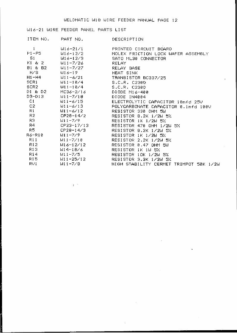
W16-21 WIRE FEEDER PANEL PARTS L I S T
ITEM NO, PART NO. DESCR I PT I ON
1 P1 -P5
S 1 K 1 IL 2 B1 & B2
H/ S H1 -H4 SCRl SCR2 D1 84 D 2 D3-Dl3
c: 1 c2 H i R2 H3 R 4 H5
R 6 - R l 8 R 1 l R 1 2 H1 3 R14 R 1 5 RV 1
W1 6-21/1 W l 6- 1 2 / 2 W16-12/3 W I 1 -7/26 W 1 1 -7/27 W16-l? W1 1-6/21 W1 1 - 1 8/4 W1 1 -1 8 /4 MC36-2/16 Wll-7/18 W1 1-6/15 W1 1-6/13 W1 1 - 6 / I 2 CP28-14/2 W 1 1-7/Y CP23-17/13 CP21- 14/3 W 1 1 -7 /? W11-7/10 h11 6-1 2/12 W1 4-1 8/6 W 1 1 -7/5 W1 1-25/12 W l 1 -7/8
PRINTED CIRCUIT BOARD MOLEX FRICTION LOCK WAFER ASSEMBLY SAT0 ML38 CONNECTOR RELAY RELAY BASE HEAT SINK TRANS1 STOR BC337/25 S . C . R , C 2 3 8 0 S . C . R . C 2 3 8 D D1 ODE Pi1 6-480 D I O D E I N 4 8 0 4 ELECTRCILYTI C CAPACITOR 10mtf d Z Y J POLYCARBONATE CAPACITOR 0 . l m f d l@QU RESISTOR 338 OHM 5W RESISTOR 8.2K 1/2W 5% RES1 STOR 1K 1 / 2 W 5% RESISTOR 478 OHM 1/2W 5% RESISTOR 8.2K 1/2W 5% RESI STOR 1 K 1/2W 5% RESISTOR 2,2K 1/2W 5% RESISTOR 0 . 4 7 OHM 5W
RESISTOR 1OK 1/2W 5% RESISVCIR 3.3K 1/2W 5% H I G H S T A B I L I T Y CERMET TRIMPOT 58K 1/2W
RESI STOR 1 K 1W 5%
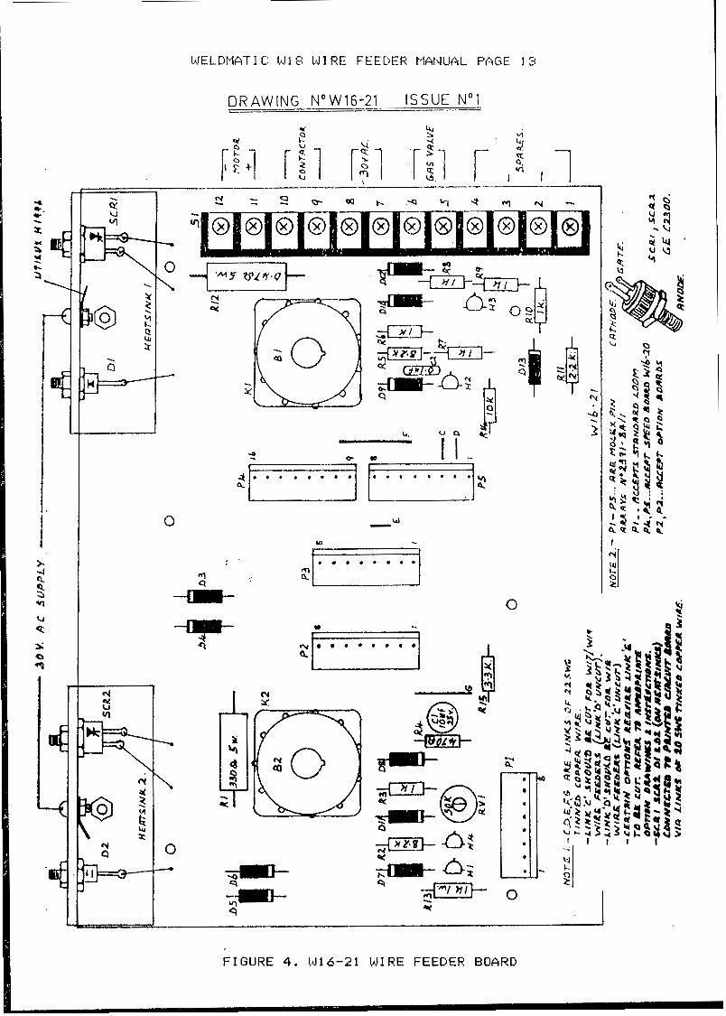
WELCNATI C: W 1 8 W 1 RE FEEDER tlANUAL PAGE 13
DRAWING N"W16-21 ISSUE NO1
l" 0
r t d I I i I p X 4
f ry X
0 .. *
n
Ei
0
I
FIGURE 4. I d l 6 - 2 1 bJIRE FEEDER BOARD
L

WELDPIATIC W1 I W1 RE FEEDER MANUAL PAGE 1 4
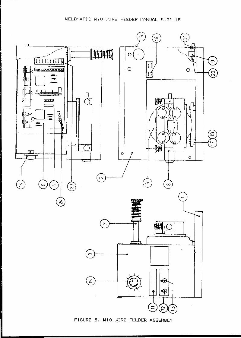
DRAWING NO.Wl8-82 PARTS L I S T
ITEM NO. PART NO. DESCHIPTlON
1 W1 7-1 l WIRE FEEDER BASE 2 W17-12 W 1 HE FEEDER CASE 3 W17-13/8 FRONT PANEL 4 W1 6-28 MOTOR SPEED CONTROL ROARD 5 W16-21 MOTHER BOARD d W16-18 W1 HE FEED MOTOR 7 AM1 77 SPOOL HOLDER ASSEMBLY 8 W15 FOUR ROLL D R I V E ASSEMBLY 9 W1-33/1 GAS VALVE
1 1 W17-8/11 I t4D I CATOH L I GHT 12 WI -19 ON/OFF SWITCH 13 W17-8/13 INCH PURGE SWITCH 1 4 W1 1 - O W 1 5 bJIRE SPEED POTENTIOMETER 15 bJ11 - @ / l 6 KNOB 16 K3 1 CONTROL SOCKET 17
19 20 21 23 24 25
18 MC1 1 - 3 w 2 Id1 1-13 W I N44 W1 1-1 1/1 W17-14/1 W 1 7-1 5 W 17-8/24 AM1 33
NYLON INSULATING BUSHES MOUNT I NG I NSULATORS TYPE NO./SERIAL NO. NAMEPLATE HOSE BARB GAS VALUE CONNECTOR TERMINAL NAMEPLATE LOOM ASSEMBLY SPOOL DUST COWER (NOT SHOWN)
PQ n
;:5 O 0 1 0
r
n
0
0-
FIGURE 5 . W18 WIRE FEEDER ASSEMBLY

IdELDMATIC: W18 bJ I HE FEEDER MANUAL PAGE l 6
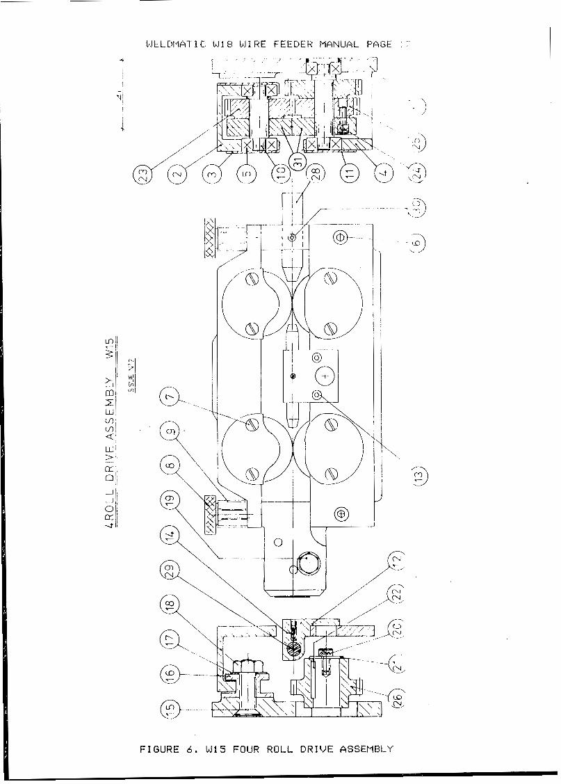
Id15 FOUR ROLL DRIUE ASSEIIBLY
ITEM NO. PART NO.
1 2 3 4 5 6 7 8 9
18 1 1 12 13 1 4 15 1L 17 18 19 28 21 22 2 3 24
25-27 2s 29 30 31
W15-2 W1 5-3 W15-4/1 W15-5 W i 5 - 1 / 5
wz-18 w2-12 W I S-6 W1 5-4 W 15-8
W 15-9
ld6-26/18
W 15-28
DESCRIPTION
4 ROLL DRIVE BODY 4 ROLL DRIVE TOP ROLLER HOUSIF4G TOP BEARING CAPS OUTER BEAR1 N O SUPPCIRT BALL BEARING M 6 X 16 SOCKET CAP SCREW 3/16"W X 1/4" RH SCREW
COMPRESSION SPRING
BOTTOM BEARING CAPS CENTRE G U I DE HOLDER M 4 X 18 SOCKET CAP SCREW M5 X 1 8 SOCKET FLAT POINT GRUB SCREW M 8 X 35 SOCKET C/SNK SCRElJ
8" SHAKPROOF WASHER M8 HEX NUT 3./9"W X 5/8" HH SET SCREW
WASHER DR I VE KEY DRIVEN GEAR WHEEL NO .8-32 UNC X 1/2" SOCKET CAP SCREW ALTERNATIVE GEAR RATIOS (SEE TABLE] INPLlT WIRE GUIDE (SEE TABLE) CENTRE W1 RE GUIDE (SEE TABLE)
DRIVE ROLLS (SEE TABLE)
TENS l 01.1 ADJUST1 NG SCREW
TOP HOLLER SHAFT
STEADY BLCK:K
t.15 X 12 SOCKET CAP SCREW
1/4l1W X 1/2" SOCKET GRUB SCREW
- 1 U!
i
1JELDtWTI C: W 1 8 W1 RE FEEDER MANUAL PAGE 1 r'
FIGURE 6 . W15 FOUR ROLL D R I V E ASSEMBLY
WEL.DIIAT1 C: W1 8 W1 RE FEEDER MANUAL PAGE 1 E:
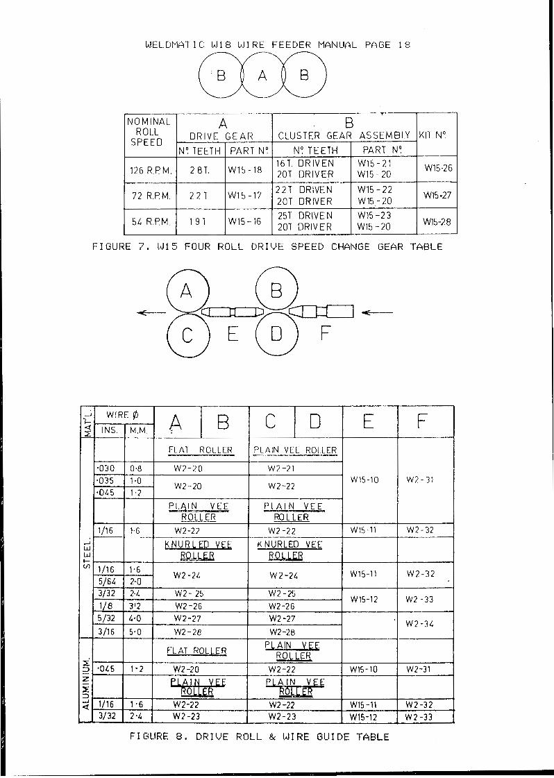
A B KULL
SPEED DRIVE GEAR CLUSTER GEAR ASSEMBLY KIT No No 1EETI-i PART No N9 TEETH PART N9
16 l. OR I V EN W15-21 126 R.PM. 2 BT. W15-18 20T 0RIVE.R W15 - 20 W15-26
22T DRIVEN W15 - 22 W15 -20 72 R.PM. 2 2 T W1 5 -17 20T DRIVER
W15.27
25T DRIVEN W15 -23 5L R.PM 19 1 W15-16 20T DR,VER W15 - 20 W15-28
F IGURE 7 . 141 5 FOUR R O L L D R I V E SPEED CHANGE GEAR T A B L E
f" t"
I 1.030 i o.8 i w 2 - 2 1 I I
w 2 - 2 0 -
I I
a035 1.0 - 0 L 5 1 a 2
w 2 - 2 0 w1s-l0
w 2 - 2 2
PLAIN VEE f 'LAIN V E E ROLLER ROLLER
7 W2 - 31
3 W 2 - 3 2
W 2 - 3 2 * I
"1 W2 - 3 3
W 2 -3L
4 W2-31
FIGURE 8. D R I V E ROLL & WIRE GUIDE TABLE

WELDMATIC W18 WIRE FEE@ER MANUAL PAGE 19
SPOOL HOLDER 8 WIRE COIL HOLDER ASSEMBLIES C -__ -_____ " _"
SPOOL HOLDER ASSEMBLY AM177
ITEM
1 2 3 4 5 6 7 0 9 10 11
DESCRIPTION
PLASTIC MOULDING FIBRE WASHER TAB WASHER SHAFT NYLOC N U T . WAVE WASHER R CLIP THRUST WASHER 3/8" 8 FLAT WASHER 3/8" Q) SPRING WASHER 3/8" W X 1" SCREW
PART NO.
AM133-l AM133-2 AM177-3 AM1 77-4 AM177-5 MCll-65/17 AM133-3 Wll-9/1
COIL HOLDER ASSEMBLY AM174 I
ITEM -
1 2 3
DESCRIPTION
SPIDER CLAMP 4'' W WING NUT
PART NO.
AM174-1 AMl74-2

WELDMATIC: W18 W I R E FEEDER PlANClAL PAGE
I
-1
LJ 0 3 c r) x 7
3
I C I I
2H" t -Y A I . l \ \ \ \
6 - 1 0.-
I l

SAFE 1’IIAcTI CI:S IN U S I N G W E I ~ I I I N G g U l PMUNT -
Produced by Welding I n d u s t r i e s of A u s t r a l i a P t y . L t d . i n the i n t e r e s t s of improv ing ope ra to r s a fe ty . These no tes s h o u l d be considered o n l y as a basic gu ide t o Sa fe Working Hab i t s . A f u l l l i s t of S tanda rds pe r t a in ing t o i n d u s t r y i s a v a i l a b l e from the S t anda rds Assoc ia t ion of A u s t r a l i a , also v a r i o u s S t a t e E l e c t r i c i t y A u t h o r i t i e s , D e p a r t m e n t s of Labour and Indus t ry or Mines Depart- ment and o the r Local Heal th o r S a f e t y I n s p e c t i o n A u t h o r i t i e s may have add i t iona l r equ i r emen t s .
1. A n e a t u n c l u t t e r e d work a r e a m k e s €or sa fe work ing hab i t s .
2 . Bum Prevent ion
The welding arc is i n t e n s e a n d v i s i b l y b r i g h t . Its rad ia t ion can damage e y e s , p e n e t r a t e l i g h t w e i g h t c l o t h i n g , r e f l e c t f r o m l i g h t - c o l o u r e d s u r f a c e s , and bu rn t h e s k i n and eyes . Skin burns resemble acute sunburn , those from gas - sh ie lded arcs are mre s e v e r e a n d p a i n f u l .
Wear p r o t e c t i v e c l o t h i n g - l e a t h e r (or asbestos) g a u n t l e t g l o v e s , h a t , a n d s a f e t y - t o e boots. But ton shirt c o l l a r a n d pocket f l aps , and wea r cu f f l e s s t r o u s e r s t o a v o i d e n t r y of sparks and s lag .
NEVER L O O K A T AN ARC WITHOUT PROTECTION.
Wear helmet with safety g o g g l e s o r glasses w i t h s i d e s h i e l d s u n d e r n e a t h , a p p r o p r i a t e f i l t e r lenses or plates ( p r o t e c t e d b y c l e a r c o v e r gl .ass ) . T h i s is a MUST €or weld ing or cu t t ing , ( and ch ipp ing) to p r o t e c t t h e e y e s f r o m rad ian t ene rgy and f l y ing me ta l , Rep lace cove r g l a s s when b r o k e n , p i t t e d , o r s p a t t e r e d .
Avoid oily o r g r e a s y c l o t h i n g . A spark may i g n i t e them. Hot metal such as e l e c t r o d e stubs and workpieces should never he handled without gloves.
Ear plugs should be worn when w e l d i n g i n o v e r h e a d p o s i t i o n s or i n a conf ined space. A h a r d h a t s h o u l d be worn when o t h e r s work overhead.
< ‘
Flammable hair P r e p a r a t i o n s 6hould not be used by pe r sons i n t end ing t o weld or c u t .
3. Toxic Fume Preven t ion
A d e q u a t e v e n t i l a t i o n i s essential. s e v e r e d i s c o m f o r t , i l l n e s s or death can r e s u l t from fumes, vapors, h e a t , o r oxygen enrichment or d e p l e t i o n that w e l d i n g (or c u t t i n g ) may produce. Prevent them w i t h a d e q u a t e v e n t i l a t i o n . NEVER v e n t i l a t e w i t h oxygen.
Lead, cadium, z i n c , mercury, and beryllium b e a r i n g and similar m a t e r i a l s when welded (or c u t ) may produce harmful concent ra t ions of toxic fumes. Adequate local exhaus t v e n t i l a t i o n muet be used, or each pereon i n the area as well as the opermr m u s t wear an a i r - s u p p l i e d r e e p i r a t o r . For &wyllium, h t h must be used. Metals coated w i t h or m n t a i n i n g m a t e r i a l s that emit fumes should not be h e a t e d unlese c o a t i n g l a r a m v e d f r o m t h e work B u r f a c e , t h e area is well v e n t i l a t e d , or t h e o p e r a t o r w e a r s a n a i r - s u p p l i e d r e e p i r a t o r ,
Work i n a conf ined apace on ly while it is b e i n g v e n t i l a t e d a n d , if neceeaa ry , w h i l e w e a r i n g a i r - s u p p l i e d r e s p i r a t o r .
Vapr8 fr,om c h l o r i n a t e d s o l v e n t s c a n be- decomposed by t h e h e a t of the arc (or flame) t o form PHOSGENE, a h i g h l y toxic gas, and l u n g a n d e y e i r r i t a t i n g products. The u l t r a - v i o l e t ( r a d i a n t ) e n e r g y of t h e a r c c a n a180 decompose t r i c h l o r e t h y l e n e a n d p e r c h l o r e t h y l e n e vapors to form phO8genO. Do not WELD or cut where f o l v e n t vapor8 can be drawn into the w e l d i n g o r c u t t i n g a t m s p h e r e or where the radiant energy can p e n e t r a t e t o a t m a p h e r e s c o n t a i n i n g e v e n minute amunts of t r i c h l o r e t h y l e n e o r p e r c h o l o r e t h y l e n e .

4 . F i r - t ? and I:x ~los ic~r l l ~ r ( ! v c ~ 1 1 t i o r l
0u:;es of f i r e and explosion t11-f::- Combusti.bles reached b y i t r c a r c , f lame, f l y - i n g sparks , hot s l a g , o r heat.t:tl m f - c > r i a l ; misuse of corn1)r-c:;sctl gases and c y l . i n - d e r s ; and short c i r c u i t s .
13c aware t h a t f l y i n g s p a r k s 01- f . a l l i r ; g s l a g c a n pass through c r a c k s , a long pipes , through windows o r doors, and throuyh w a l l o r floor openings, out- of si~ghe of the goggled operator . Sparks and s l a g c a n f l y 10 metres
To preven t f i r e s and exp los ions :- Keep equipment c lean and operable , f ree of o i l , grease, and ( i n e l e c t r i c a l p a r t s ) of m e t a l l i c p a r t i c l e s t h a t can cause s h o r t c i rcu i t s .
I f combust ibles a r e i n area, do NOT weld ox c u t . Move t h e work if p r a c t i c a b l e , t o a n area free of combust ib les . Avoid p a i n t s p r a y rooms, d i p t a n k s , s t o r a g e a r e a s , v e n t i l a t o r s . If the work can not be m v e d , move combustibles a t l ea s t 10 metres away o u t of reach of sparks and h e a t ; or protect a g a i n s t i g n i t i o n w i t h s u i t a b l e a n d s n u g - f i t t i n g f i r e - r e s i s t a n t c o v e r s or s h i e l d s .
Walls touch ing combus t ib l e s on oppos i t e s ides shou ld no t be welded on (or c u t ) . Walls ,ceiLings, and floor n e a r work should be p r o t e c t e d by h e a t - r e s i s t a n t covers or s h i e l d s . Fire watcher must be s t a n d i n g by wi th su i tab le f i r e e x t i n g u i s h i n g e q u i p m e n t during and for some time a f t e r w e l d i n g or c u t t i n g i f :
(1) c o m b u s t i b l e s ( i n c l u d i n g b u i l d i n g c o n s t r u c t i o n ) a r e w i t h i n 10 metres. (11) combustibles a r e f u r t h e r t h a n 10 metres b u t can be i g n i t e d by sparks . (111) openings (concealed o r v i s ib l e ) i n f l o o r s or walls w i t h i n 1 0 metres
(1V) combus t ib l e s ad j acen t t o w a l l s , c e i l i n g s , roofs, or m t a l p a r t i t i o n s may expose c o m b u s t i b l e s t o s p a r k s .
can be i g n i t e d by r a d i a n t or conducted hea t .
After work is done, check that area is free of sparks, glowing emtsers, and flames
An empty con ta ine r t ha t%e ld combus t ib l e s , or can produce f lamable vapors when heated, must never be welded on o r c u t , u n l e s s c o n t a i n e r ha6 f i r s t b e e n cleaned as d e s c r i b e d i n As.1674-1974, t h e S . A . A . Cutting and Welding Safety Code. This i n c l u d e s : a thorough steam or c a u s t i c c l e a n i n g (or a s o l v e n t o r water-washing, d e p e n d i n g o n t h e c o m b u s t i b l e ' s s o l u b i l i t y ) followed by p u r g i n g a n d i n e r t i n g with n i t r o g e n or carbn dioxide, and u s ing protect ive equipment as recommended i n AS.1674-1974. W a t e r - f i l l i n g j u s t below w o r k i n g l e v e l may s u b s t i t u t e for i n e r t i n g .
Hollow c a s t i n g s or con ta ine r s mus t be vented before welding o r c u t t i n g . They can explode. Never weld or c u t w h e r e t h e a i r m y c o n t a i n flammable d u s t , gas, or l i q u i d vapors such as petrol) . 5. Shock Prevent ion
Exposed conductors o r other bare metal i n the welding c i r c u i t , or ungrounded e l e c t r i c a l l y a l ive equipment can f a t a l l y shock a person whose body becomes a con- d u c t o r . Ensure that t h e maahine is c o r r e c t l y c o n n e c t e d a n d e a r t h e d . If Uflaure have machine i n s t a l l e d by a q u a l i f i e d electrician. On mobile or portable e q u i p m n t , r e g u l a r l y i n s p e c t c o n d i t i o n of t r a i l i n g power laads and connec t ing p lugs . Itep8i.r or replace damaged l eads .
6. Electrode Holders and Connectors
F u l l y i n s u l a t e d e l e c t r o d e h o l d e r s should be used . Do n o t USQ holders with p r o t r u d i n g 8crew8. F u l l y i n s u l a t e d l o c k - t y p e c o n n e c t o r e should be used to j o i n welding Cable l e n g t h s .
7 . Terminals
Terminals and other exposed parts of electrical units should have i n s u l a t e d knobs or
_ -
covers s e c u r e d before operation.


![Visual Weld Inspection Guidelines Attachment A - …2].pdf · Visual Weld Inspection Guidelines Attachment A ... approved weld inspector shall document weld inspection results using](https://img.pdfslide.us/doc/110x75/5a78aa797f8b9a21538b97b6/visual-weld-inspection-guidelines-attachment-a-2pdfvisual-weld-inspection.jpg)