Embed Size (px)
Citation preview
No. 832,666. PATENTED OCT. 9, 1906. > G. HAMANN. '
CALCULATING MACHINE. APPLICATION FILED MAR. 28, 19136. 7
6 SHEETS-SHEET l.
lire/2502': é’lu'g'rteélamizn
PATENTED OCT. 9, 1906. NO. 832,666. O. HAMANN.
CALCULATING MACHINE‘ APPLIGATION FILED MAE.28,1905.
6 SHEETS—SHEET 2‘
A ‘7 Ill/Ill 1 ,1 .
4:: 1.: Z
W m ‘ v
. w
Wm mm
lullllllllxl
No. 832,666. PATENTED OCT. 9, 1906. C. HAMANN.
CALCULATING MACHINE. ‘APPLICATION FILED MAB..28,1905.
5 sHn'BTs-smm' a.
1” 1%
\L/ 9» _ 0 0a 6 B /0 .. a
Mia/V7112 o amjw 6.1%. I“ E: 4m I
, h” n W My W m. m g 7 .6
l n z W” w
Wm 1 , n
5
A W m,
C W x Wm
. a. m 8
6 l w 3 0 .. f, f a wimp /.
1 I
p K" 4 m%/
:4 1
VPATENTED 001?. 9, 1906. No. 832,666. 0. HAMANN. v
CALCULATING MACHINE. APPLIUATION FIL'ED MAR.28, 1905.
5 SHEETS-SHEET 4.
I'IIIIII
IIIIIIIII4
N0- 832,666. PATENTED 00:6. 9, 1906. c. HAMANN. I
CALCULATING MACHINE. APPLICATION FILED IAR. 28,1905.
6 SHEETS-SHEET 5.
M//// /X/ / A!
(1 ‘V/ //// /
‘ ?izmm'ew
)ZWOIM
10
, ferent lengths.
25
35
45
50
UNITED STATES ‘PATENT. OFFICE. ,CHRISTEL HAMANN, OF FRIEDENAU, NEAR BERLIN, GERMANY.
CALCULATING-MACHINE. No. 832,666. Speci?cation of Letters Patent. Patent-ed Oct. 9, 1906.‘
Application ?led March 28, 1.966. Serial No. 252.516.
To all whom it may concern: Be it known that I, CHRisTEnHAMANN,
engineer, a citizen of Germany, and a resident of Friedenau, near Berlin, Germany, (whose post-office address is Hedwigstrasse 17 ,) have invented certainnew and useful Improve ments in Calculating-Machines, of which the following is a speci?cation. My invention relates to an improved cal
culating-machine. ' In prior calculators toothed wheels'having
adjustable gear-teeth or the like have been employed to give the result. Another well known means for obtaining the part products is the stepped roller ?rst used by Leibnitz and consisting of a'cylind er with teeth of dif
According to my invention I dispense with such devices and use instead a single disk provided with teeth disposed stepwise. The toothed wheels which give the part products can be caused to move re dially of this disk and can be rotated by it corresponding to‘ the position occupied. By reason of thelcircular arrangement of
the toothed wheels, rendered necessary owing to the employment of a disk, the parts of the machine can be compactly located in a very small space. The machine is thus very light and readily partible,~ being well adapted for the pocket. The machine can be used to calculate any
number of figures, as the circular arrange ment of the parts imposes no limit such as there is ‘in the case of machines with ?gures located one beside the other.‘
'. One form of construction of the machine is shown in the accompanying drawings.
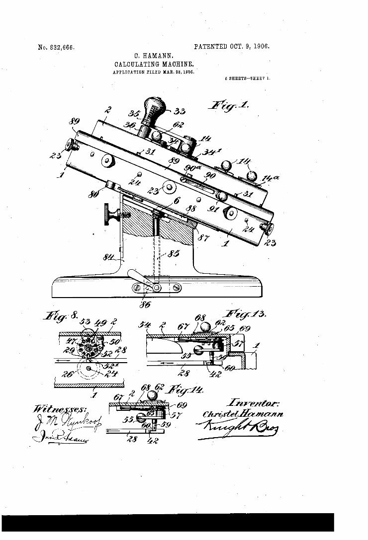
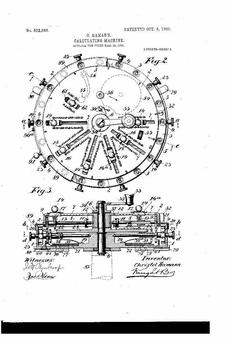
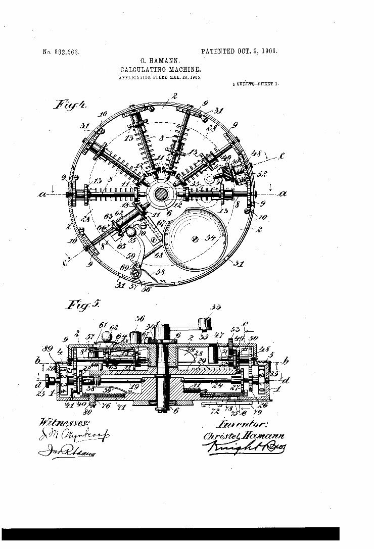
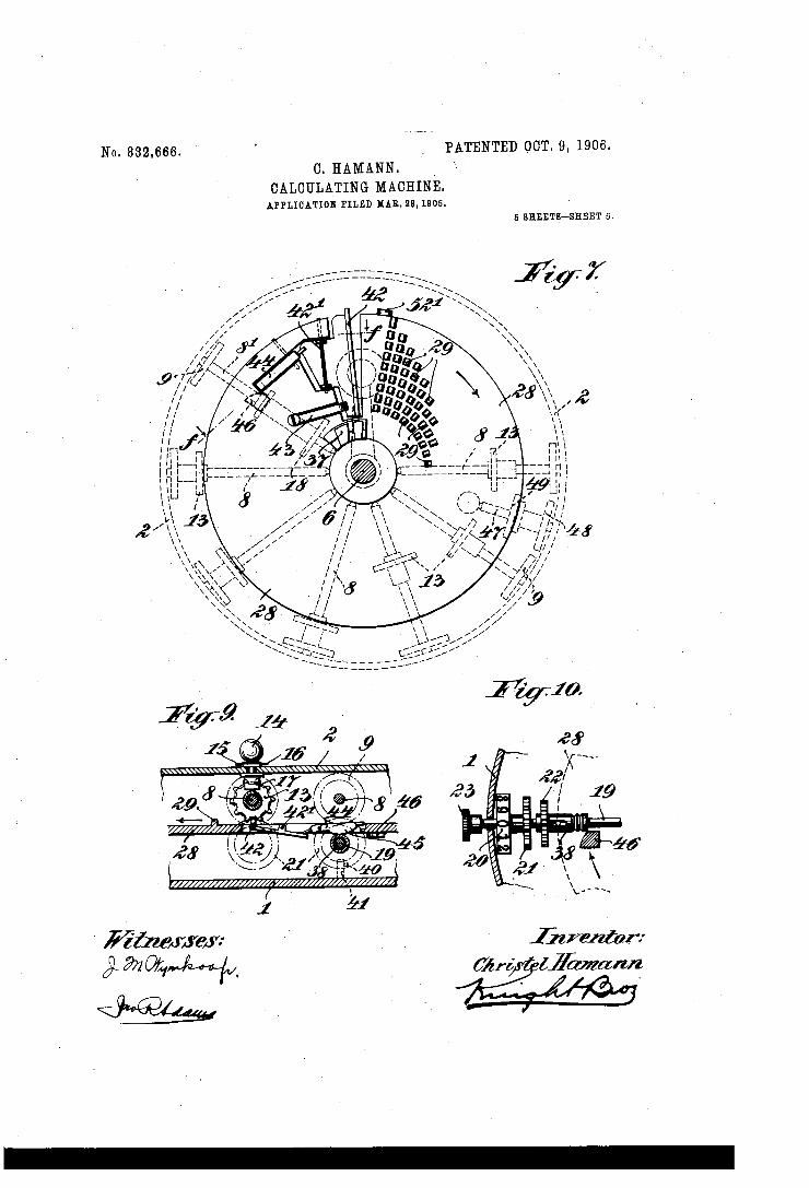
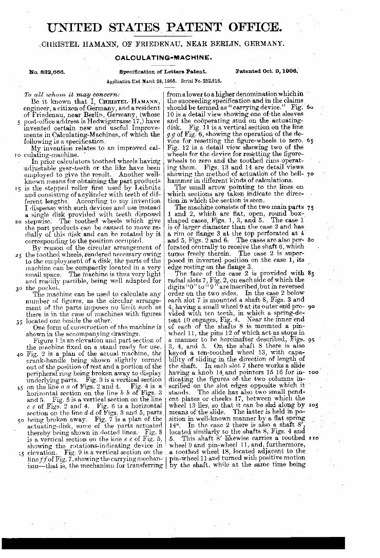
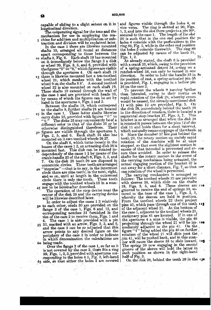
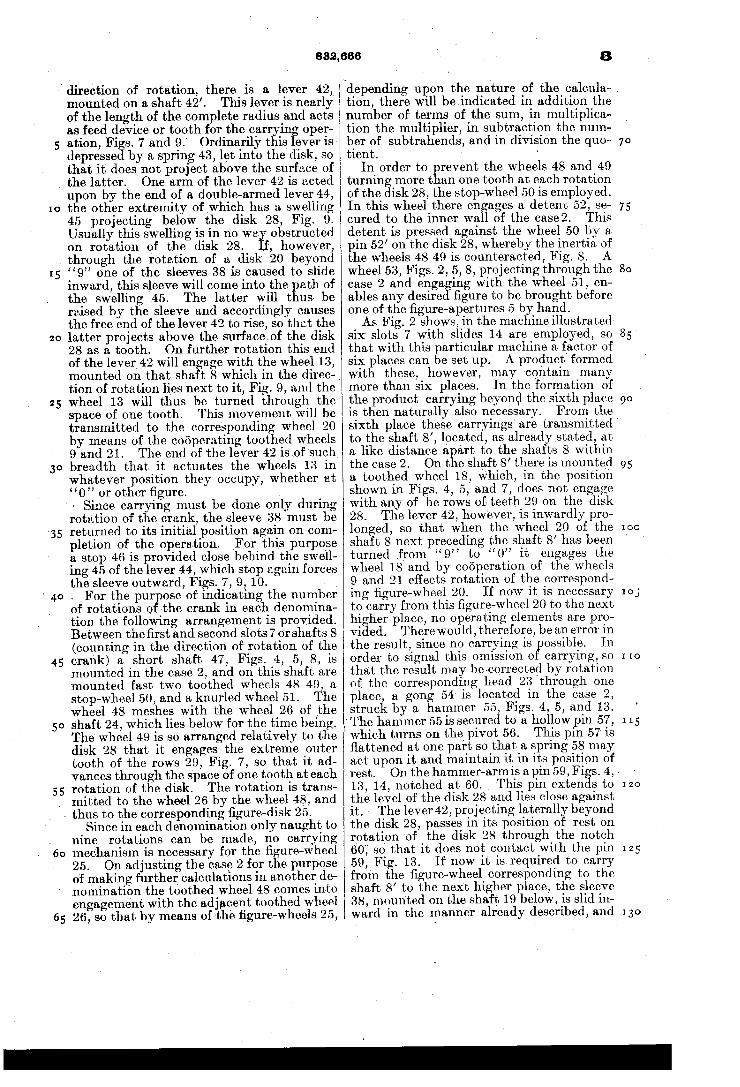
Figure 1 is an elevation and part section of the machine ?xed on a stand ready for use. Fig. 2 is a plan of the actual machine, the crank-handle being shown slightly turned out of the position» of rest and a portion of the peripheral ring being broken away to display underlying parts. ig. 3 is a vertical section on the line a c of Figs. ‘2 and 4. v Fig. 4 is a horizontal section on the line b b of Figs. 3 and 5. Fig. 5 is a vertical'section on the line 0 c of Figs. 2 and 4. Fig. 6 is a horizontal section on the line d d of Figs. 3 and 5, parts being broken away. Fig. 7 is a plan of the actuating-disk, some of the parts actuated thereby being shown in dotted lines. Fig. 8 is a vertical section on the line 6 e of Fig. 5, showing the rotations-indicating device in elevation. Fig. 9 is a vertical section on the line f_ f of Fig. 7, showing the carrying mechan-‘ ism——that is, the mechanism for transferring
_ the shaft.
,means of'the slide.
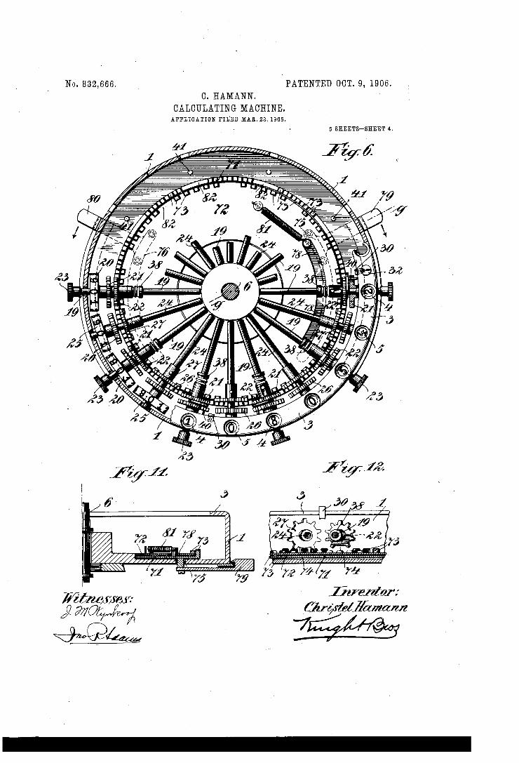
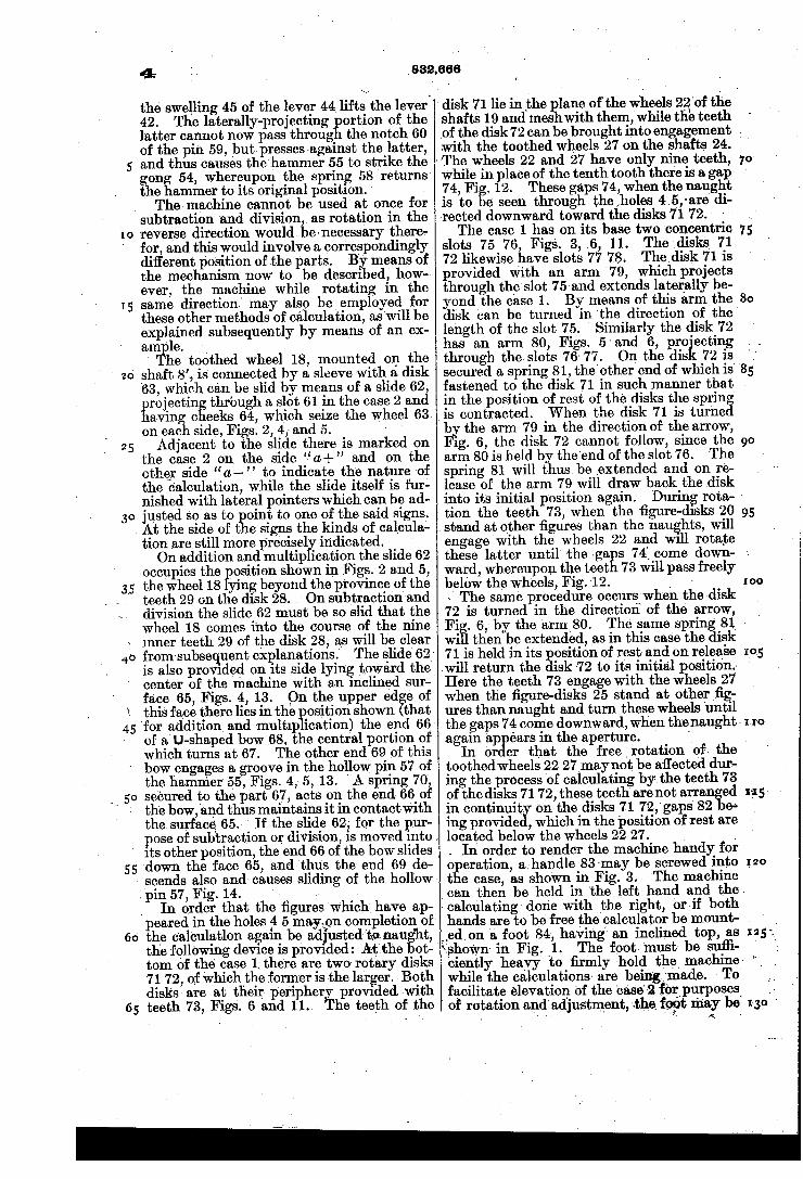
from a lower to a higher denomination which in - the succeeding speci?cation and in the claims‘ should be termed as “ carrying device.” Fig. 10 is a detail view showing one ofthe sleeves and the cooperating stud on the-actuating disk. Fig. 11 is a vertical section on the line g g of Fig. 6, showin the operation of the de vice for resetting the ?gure-wheels to zero. Fig. 12 is a detail view showing two of the wheels for the device for resetting the ?gure— wheels to zero and the toothed rims operat ing them. Figs. 13 and 14 are detail views showing the method of actuation of the hell hammer in different kinds of calculations. The small arrow pointing to the lines on
which sections are taken indicate the direc tion in which the section is seen. ' The machine consists of the two main parts
1 and 2, which are ?at, open, round box sha ed cases, Figs. 1, 3, and 5. The case 1 is 0 larger diameter than the case 2 and has a rim or flange 3 at the top perforated at 4' and 5, Figs. 2 and 6-. The cases are also per
60
65
.15
forated‘centrally to receive the shaft 6, which ' turns freely therein. The case 2 is super posed viii-inverted position on the case 1, its v_ edge resting'on the flange 3. .The face of the case 2 is rovided with
radial slots 7, Fig. 2, on each si e of which the digits “0” to ?‘ 9 ” are inscribed,but in reversed order on the two sides. In the case 2 below each slot 7 is mounted a shaft 8, Figs. 3 and 4, having a small wheel 9 at its outer end pro vided with ten teeth, in which a spring-de tent 10' en a es, Fig. 4. Near the inner end of each 0 tie shafts 8 is mounted a pin wheel 11, the ins 12 of which act as sto s in a manner to e hereinafter described, Fi s. 3, 4, and 5. vOn the shaft 8 there is aFso keyed a ten-toothed wheel 13, with capa bility of sliding in the direction of length of
In each slot 7 there works a slide having a knob 14, and pointers 15 16 for in dicating the figures of the two columns in
9O
95'
I00
scribed on the slot edges opposite which it ' stands. The slide has ‘also two small end ent plates or cheeks 17, between whic the wheel 13 lies, so that it can be slid along by
The latter is held in po sition in well-known manner b a ?at spring 14*‘. In the case 2 there is also a shaft 8’, located similarly to the shafts 8, Figs. 4 and 5. This shaft 8’ likewise carries a toothed wheel 9 and pin-wheel 11, and, furthermore, a toothed wheel 18, located adjacent to the in-wheel 11 and turned with positive motion
by the shaft, while at the same ‘time being
105
20
25
is
, crank-han
~ concentric circles.
40
.45.
55
capable of sliding to a slight'extent on it in lon 'tudinal direction. ' I 1
he cooperating signal for the tens and the mechanism for use "in em loyin the ma chine for addition and multiplication or sub traction and division will be explained later.‘ In the case 1 there are likewise mounted
shafts 19,- arran ed all round at. distances. 9. art correspon ingv to those between the s afts 8, Fi . 6. ' Each shaft 19 has mounted on it imme 'ately below the ?ange 3 a disk or wheel 20, Figs. 3, 5, and 6, provided with ‘the ?gures “0” to “9,” which ?gures are visible through the apertures 4. On each shaft 19 there 1s likewise mounted fast a: ten-toothed wheel 21, which meshes with the toothed wheel 9 on the shafts 8 8’. A second toothed wheel 22 is also mounted on each shaft 19. These shafts 19 extend through the wall of the case 1 and are provided with heads 23, by means of which the ? ures can be set by hand in the a ertures 4, igs. 1 and 2. Between t e shafts 19, which correspond
to the shafts 8, further shafts 24 are located in the case 1. carry disks 25, provided with ?gures “ 0 ”, 'to “ 9.’ The disks 25 may conveniently be'of a different color to that of the disks 20 or be otherwise distinguished therefrom. Their
ures are visible through the apertures 5, Figs. 2, 5, and 6.' Each shaft 24 also has mounted on it two toothed wheels 26 27.
On the shaft'?, which turns loosely in the bosses of the cases 1 2, ‘an actuating-disk 28 is mounted fast. This disk can be rotated in-v dependentliy of the cases 1 2_ by means of the
7. On the‘disk 28 teeth 29 are disposed in These teeth are arranged
‘ ‘stepwise” —that is to say, in the innermost circle there are nine teeth; in the next, eight, and so on, until at length in the'outermo'st‘ circle there-is only one tooth. ‘ These teeth engage with the toothed wheels, 13 in a man ner ‘to be hereinafter described. _ .The 0 eration of the stop device near the
/'center 0 the disk 28 and the carrying device will be likewise described later. - _
In order to adjust the cases 1 2 relatively to each other, studs 30 are provided on the ?ange 3 of-the case 1, Figs. ‘(Sand 12, and corresponding notches 31 furnished in the rim of the case 2 to receive them, Figs.‘ 1 and '4. The case-.1 is"also ‘provided with a . in
32, marked with an arrow, Figs. 2, 3, and) 6, I and the case 2 can be so ad'usted that this
60
arrow points to any desire ?gure on the periphery of the case 2 inorder to indicate vin- which denomination the calculations are being‘made; , ' .
Over the ?ange3 of the case 1, so far asit is not covered by the case 2, there ?ts a ring 89,-.Figs. 1, 2, 3, provided with apertures cor »resp'odding to the holes 4 5, Fig. 2, left-hand" side, so that eitherthe holes 5 ‘are covered
These latter shafts likewise
le 33 of the shaft 6, Figs. 3, 5, and’
882,666 -
and ?gures visible throu h the holes 4, or vice versa;
secured to the case 1. The lenvth of the slot 90 is such that in the one en'i position the holes 4 coincide with the perforations in the ring 89, Fig. 2, while in the other end position the holes 5 coincide therewith. The ring 89 can be adjusted by means of the knob 91, Figs. 1, 2. v ' I '
As already stated, the shaft 6 is provided ' with a crank 33, which, owing to the provision of a spring-actuated detent 34, acting on a ratchet-wheel 34, can only be turned in one direction. In order to hold the handle 33 in its position of rest, a. spring-actuated pin 35 is provided, Fig. 1, engaging in a hollow pin 36 on the case 2. To revent the wheels 9 turning farther
than lntended, owing to their inertia on rapid rotation of the ( isk 28, whereby errors would be ‘caused, the already-mentioned disk 11 with pins 12 are provided, Fig. 3. ()n the disk 28, immediately behind the teeth 29 in the direction of rotation, there is located a segmental stop-bracket 37, Figs. 3, 7. This bracket is so arranged that when. the disk 28 is rotated it passes between the pins 12 of the disk~ 11 and holds them for a short interval, which naturally means sto page of the wheels 9. Since the member 37 lies just behind the teeth 29, the rotary motion on unduly rapid rotation of the machine will be at once stopped, so that even the slightest motion in excess ofthat intended is prevented and er
The ring is s otted at 90, Figs. . 1, 2, and into the slot there projects a pin 90“,
70
1,5.
80
85
95
rors thus avoided. In order to release the - shafts for the rotary motion in'the event of the carrying mechanism being actuated, the - actual engaging portion of the bracket 37 is cut away for a short distance, Fig. 7, so that one rotation of the wheel is permitted. The carrying mechanism is arranged as
follows: The toothed wheels 22 are provided with sleeves 38, which slide on the shafts 19, Figs. 3, 5, and 6. These sleeves are grooved to receive the end of springs 39, se cured to'thebase of the case 1, Figs. 3, 5, whereby vthe sleeves are held in position. From the toothed wheels 22 there project rpins 40, which pass through one of the teeth of the adjacent wheel 21. At the bottom of the case 1, adjacent to the toothed wheels 21, stationary pins 41 are located. If in one of they apertures 4-a nine is visible, the pin 40 projecting through- the wheel 21 will lie im-_
On the . further '
ast the, -
mediately adjacent to the pin 41. ?gure “'1 ” being added the pin 40 on rotation of the wheel 21 Wlll slide _ .pin 41-, will be pushed back, and in t 1s man ner will cause the sleeve 38 to slide inward. The spring 39 now engagin in the ‘second groove of - the sleeve such ositi0n~ as shown in the right-hand half of) Fig. 3. ‘ , On the disk 28, behind the teeth 29 ‘in the
In?
I2.
W111‘ ho d the latter in '
882,666
'direction of rotation, there is a lever 42,
,the latter.
IO
20
25
45
55
mounted on a shaft 42’. This lever is nearly of the length of the complete radius and acts as feed device or tooth for the carrying oper ation, Fi s. 7 and 9. Ordinarily this lever is depresse by a spring 43, let into the disk, so that it does not project above the surface of
One arm of the lever 42 is acted upon by the end of a double-armed lever 44, the other extremity of which has a swelling 45 projecting below the disk 28, Fig. I 9. Usually this swelling is in no we obstructed on rotation of the disk 28. ,f, however, through the rotation of a disk 20 beyond “9” one of the sleeves 38 is caused to slide inward, this sleeve will come into the ath of the swelling 45. The latter will t us» be raised by the sleeve and accordingly causes the free end of the lever 42 to rise, so that the latter projects above the surfaceof the disk 28 as a tooth. On further rotation this end of the lever 42 will'envage with the wheel 13, mounted on that ‘shaft tion of rotation lies next to it, Fig. 9, and the wheel 13 will thus be turned through the space of one tooth. This movement will be transmitted to the corresponding wheel 20 by means of the cor'iperating toothed wheels 9 and 21. breadth that it actuates the wheels 13 in whatever position they occupy, whether at “0” or other figure.
~ Since carrying must be done only during rotation of the crank, the sleeve 38 must be returned to its initial position again on com pletion of the operation. For this purpose a stop 46 is provided close behind the swell ing 45 of the lever 44, ‘which stop again forces the sleeve outward, Figs. 7, 9, 10.
For the pur ose of indicating the number of rotations o the crank in each denomina tion the following arrangement is provided. Between the ?rst and second slots 7 or shafts 8 (counting in the direction of rotation-of the crank) a short shaft 47, Figs. 4, 5, 8, is mounted in the case 2, and on this shaft are mounted fast two toothed wheels 48 49, a stop-wheel 50, and a knurled wheel 51. The wheel 48 meshes with the wheel 26 of the shaft 24, which lies below for the time being. The wheel 49 is so arranged relatively to the disk 28 that it engages the extreme outer tooth of the rows 29, Fig. 7, so that it ad vances through the space of one tooth at each rotation of the disk. The rotation is trans— mitted to the wheel 26 by the wheel 48, and
I 1 thus to the corresponding ?gure-disk 25.
V60
65
Since in each denomination only naught to nine rotations can be made, no carrying mechanism is necessary for the ?gure-wheel 25. On adjusting the case 2 for the purpose of making further calculations in another de nomination the toothed wheel 48 comes into engagement with the adjacent toothed wheel 26, so that by means of the ?gure-wheels 25, '
8 which in the direc-,
The end of ‘the lever 42 is of ‘such,
8
tion, there will be indicated in addition the number of terms of the‘ sum, in multiplica tion the multiplier, in subtraction the num ber of subtrahends, and in division the quo~ tient. - ‘
In order to revent the wheels 48 and 49 turning more t an one tooth at each rotation of the disk 28, the stop-wheel 50 is employed. In this wheel there engages a detent 52, se cured to the inner Wall of the case 2. This detent is pressed against the wheel 50 by a pin 52’ on the disk 28, whereby the inertia of the wheels 48 49 is counteracted, Fig. 8. A wheel 53, Figs. 2, 5, 8, projecting through’ the case 2 and engaging with the wheel 51, en ables any desired ?gure to be brought before one of the ?gure-apertures 5 by hand. As Fig. 2 shows, in the machine illustrated
six slots 7 with slides 14 are employed, so that with this particular machine a factor of six places can be set up. A product formed with these, however, may contain many more than six places. In the formation of the product carrying beyond the sixth place is then naturally also necessary. From the sixth ‘place these carryings' are transmitted to the shaft 8’, located, as already stated, at a like distance a art to the shafts 8 Within the case 2. On t e shaft 8’ there is mounted a toothed wheel 18, which, in the position shown in Figs. 4, 5, and 7, does not engage with any of he rows of teeth 29 on the disk 28. The lever 42, however, is inwardly pro longed, so that when the wheel 20 of the shaft 8 next preceding the shaft 8’ has been turned from “9” to “0” it engages the wheel 18 and by cooperation of the wheels
‘depending upon the nature of the calcula~ .
75
85
95
IOC
9 and 21 effects rotation of the correspond- ‘ ing figure-wheel'20. If now it is necessary to carry from this ?gure-Wheel 20 to the next higher place, no operating elements are pro vided. There would, therefore, be an error in the result, since no carrying is fpossible. In order to signal this omission o carrying, so that the result may be-corrected by rotation of the corresponding head 23 through one place, a gong 54’ is located in the case 2, struck by a hammer 55, Figs. 4, 5, and 13. ‘The hammer 55 is secured to a hollow pin 57, which turns on the pivot 56. This pin 57 is ?attened at one part so that a spring 58 may act upon it and maintain it in its position of rest. 13, 14, notched at 60. This pin extends to the level of the disk 28 and lies close against it. The lever 42, projecting laterally beyond the disk 28, passes in its position of rest on rotation of the disk 28 through the notch 60,‘ so that it does not contact with the pin 59, Fig. 13. If now it is required to carry from the ?gure-wheel corresponding to the shaft 8’ to the next higher place, the sleeve 38, mounted on the shaft 19 below, is slid in~ ward in the manner already described, and
On the hammer-arm is a pin 59, Figs. 4, -
IOJ
IIO
115
I20
I25
130
10
25
4:
the swelling 45 of the lever 44 lifts- the lever. 42. The laterally-projecting ortion of the latter cannot now pass throug the notch 60 .of the pin 59, but-presses ‘against the latter, and thus causes the hammer 55 to strike the gong 54, whereupon the spring 58 returns
- the hammer to its original position. ' The machine cannot be used‘ at once for
subtraction and division, as rotation in the reverse direction would be-necessary there. for, and this would involve a correspondingly different position of the parts. By means of the mechanism now to be described, how ever, the machine while rotating in the same direction' may also be employed for these other methods of calculation, as'will be explained subsequently by means of an ex
amylple. ' he toothed wheel 18, mounted on the shaft 8’, is‘ connected by a sleeve with a disk 63, which can be slid by means of a slide 62, rojecting through a slot 61 in the case 2 and
iiaving cheeks 64, which seize the wheel 63 on, each side, Figs. 2, 4, and 5. ‘ ' Adjacent to the slide there is marked on
the case 2 on the side “a.+ ” and on the other side “a,- ” to indicate the nature of the calculation, while the slide itself is fur nished with lateral pointers which can be ad 'usted so as to oint to one of the said signs.
. At the side of t e signs the kinds of calcula
3.5
tion are still more precisel indicated. On addition and multip ication the slide 62
occupies the osition shown in Figs. 2 and 5, the wheel 18 ying beyond the province of the teeth 29 on the disk 28. On subtraction and division the slide 62 must be so slid that the wheel 18 comes into the course of the nine
\ inner teeth 29 of the disk 28, as will be clear 40
45
from'subsequent explanations. The slide 62 is also provlded on its side lying toward the’ center of the machine with an inclined sur face 65, Figs. 4, 13. {On the upper ed e of this face there lies in the osition shown that 'for addition and multlp ication) the end 66' of a' U-shaped bow .68, the central portion of
- which turns at 67. The other endl69 of this bow engages a groove in the hollow pin 57 of the hammer 55', Figs. 4, 5, 13. ‘ A spring 70', secured to the part 67, acts on the end 66 of, the bow, and thus maintains it in contact with the. surface 65. ' If the slide 62,- for the pur ose of subtraction or division, is moved into .
' its other position, the end 66 of the bow slides 55
I scends also and causes sliding of the hollow> . pin 57, Fig. 14.
60'
65
down the face 65, and thus the end 69 de
In order that the ?gures which have ap peared in the holes 5 may._on completion of the calculatlon agaln be adjusted ta nau t, the following device is provided: At‘ the ot tom of the case '1. there are two- rotary disks 71 72 , of which the former is the larger. Both disks are at their periphery provided-with teeth 73, Figs. 6 and 11. The teeth of the
{shown in Fig. 41. ciently heavy to ?rmly hold the, machine while the calculations‘ are beinggmade. - To‘
832.666
disk 71 lie in the plane of‘ the ‘wheels 2201’ the ' shafts 19 and meshwith them ,while the teeth ,of the disk 72 can be brought into engagement : .with the toothed wheels 27 on the shafts 24. 'The wheels 22 vand 27 have only nine teeth, while in place of the tenth tooth there is a gap 7 4, Fig. 12. These gaps 74, when the naught is to be seen through the ,holes 4,-5,-are' di rected downward toward the disks 71 72. The case 1 has on its base two concentric
slots 75 76, Figs. 3, 6, 11. The ‘disks 71 72 likewise have slots 77 7.8. The disk 71 is provided with an arm '79, which projects through the'slot 75 and extends laterally be yond the case 1. By means of this arm the disk can be turned in ‘the direction of the length of the slot 75. ' Similarly the disk 72 has an arm 80, Figs. 5 ' and 6, pro'ecting through the slots 76‘ 77. On the dis 72 is secured a spring 81 , the'other end of which is‘
10
75
fastened to the disk 71 in such manner that - in the position of rest of the disks the spring is contracted. When‘the disk 71 is turne by the arm 79 in the direction of the arrow, Fig. 6, the disk 72 cannot follow, since the arm_80 is held by the'end of the slot 76. The spring 81 will thusbe extended and on re lease of the arm 79 will draw back the disk into its initial position again. Durin tion the teeth 73, when the ?gure-disks 20 .stand at other ?gures than the naughts, will engage'with the wheels 22 and Wlll rotate
9O
rota- '
95
these latter until‘ the ‘ga s 74" come down- ' ward, whereupon the teet 73 will pass freely below the wheels, Fig. 12. _ a 1 \ The same procedure occurs-when the disk 72 is turned in the direction of the arrow,
I00
Fi . 6, by the arm"80. The same spring 81, ‘ wi 1 then be extended, as in this case the disk 71 is held in its position of rest and on release ‘will return the disk '7 2 to its initial position; Here the teeth 73 engage with the wheels 27 when the ?gure-disks 25 stand at other?g ures than naught and turn these wheels until the gaps 74 come downward, when thenaught‘ again ap ears in the aperture.
105
In or or that the free ‘rotation vof the ’ toothedwheels 22v 27lmaynot be a?ected dur ing the process of calculating by the teeth 73 I of the disks 71 72, these teeth‘ are not arranged in continuit. on the disks 71 72,'gaps' 82 e-' ing provide , which in the position of rest are ' located below the wheels 22 27. . _ . In order to render the machine handy for o eration, ahandle 83'may be screwed into t e case, as shown in Fig. 3. The machine
hands are to be free the'calculator be mount “edon a foot 84, having an inclined top, as
The foot 'must be su?i
facilitate elevation of the case“? for purposes of rotation and adjustment, the. may be
e
no
‘can then be held in the left hand and the. calculating done with the right, or-if both
“51. ,
15
25
35
45
SO
55
65
832,666
provided with a pin 85, raised by a lever with cam 86. \ The pin 85 presses against the shaft 6 and lifts it and the case ‘2 on operation of the lever with cam 86, whereby the studs _ 30 on the rim of the case 1 are disengaged from the notches 31 in the edge of the case 2. The foot is provided with a plate 87, onto which the projecting portion 88 at the bot tom of the cased ?ts. If now a calculation-‘ for example, a multiplication-is to be under taken, the knobs 14 must be pushed along to adjust the pointers 15 to the ?gures on the left of the slots, starting from the right with the units. The knob in the slot 61 must be set to “Addition and multiplication.” The case 2 must be adjusted relatively to the case 1, so that the ?gure “1 ” stands before the ar row of the indicator 32-. In the hole 4, which lies to the left of this indicator, the units place of the result of the calculation will thus e visible, and at the indicator,‘ therefore,
~the reading of the result of the calculation commences. The ring 89 is so adjusted that the aper
tures in it coincide with the holes 5. The multiplier can thus be seen, and it can be checked whether the proper number of rota tions are made at each place.
Since between the ?rst and second slots (in the direction of rotation) the device for indi cating the number of rotations is located, the units~?gure will appear in the hole 5, located between these two slots. F or instance. if the number “463” is to be multiplied by “ 34” then in the ?rst slot the pointer 15 of the knob 14 must be set at “3,” in the next slot_at “6,” and in the third slot at “4,” Fig. 2. Owing to the knobs 14 being slid along in this man ner, the wheels 13 on the shafts 8 will be moved so that they engage with those rows of teeth 29 -on the disk 28 whose numbers of teeth correspond with the ?gures pointed to at 15. - Thus on turning the disk ‘28 by means‘ of the handle the wheel 13 of the units place comes into engagement with three teeth 29, the wheel‘ 13 of the tens place withv six teeth, and the wheel 13 of the hundreds place with four teeth. By means of the cor responding wheels 9 and 21, Fig. 3, these ro tations are transmitted to the corresponding ?gure-disks 20 and the corresponding ?gures will appear in the respective holes 4. On the next rotation this process will ‘be repeated. There will again be a rotation of the ?gure wheels 20 corresponding to the ?gures in question. Thus in the case of the number under consideration there will appear in the units place “6,” in the tens place “2,” and in the‘hundreds place‘ ‘8.” The ?gure-wheel 20 of the tens place will have now traveled be— yond' the “9,” whereby the carrying device will be adjusted so that the ?gure-wheel 20 of the hundreds lace will turn not only through the number of) teeth corresponding to the ?g use set, but (by reason of the engagement of
5
l the lever 42) also through the space of a fur?
l l
. stated.
1 .
- 11111118.
ther tooth, so that now instead of the “8” a "9” will become visible. Thus there will be read “926.” Two more turns have now to be given, whereby the artial product “ 1852” for the units place of the multiplier is formed, Fig. 2. In the hole 6 between the ?gures “2 ” and “5” the units-number “4” of-the multi plier is visible, Fig. 2. The case 2 must now e so turned relatively to the case 1 ~that in
stead of the ?gure “1 ” at the indicating-pin 32 the next ?gure on the periphery of the case 2—that is to say, the ?gure “‘ ”——comes. opposite this pin. In this manner the slot of the units place comes to rest above the tens place of the partial product. The calculation for the tens place of the multiplier can now be made. After three rotations the product ‘desired is ascertained. By rotation of the case 2 that portion of the rotations-counting mechanism lying within it is likewise ad vanced by one place. The tens-?gure of the multiplier will now become visible here. When the calculation is complete, it is only
necessary to bring the ring 89 into its other position, in which the perforations cover the holes 4, when the ?gures visible in the same give the result of the calculation. In this machine the reversing-gear usually employed in calculators for negative calculations is dis pensed with, as it would only tend to render the machine more complicated. Such calcu lations, therefore, are to be made in such manner that the decadal completion of the subtrahend is introduced into the adjusting device, so that the calculation can be com pleted with the same crank rotation as for addition. .
In order to render mental calculation un necessary for the decimal completion, a row of ?gures in reversed. order is provided at the right-hand side of the slots 7, as already
These ?gures give the decadal com— pletion of the corresponding ?gures on the opposite side of the slot. Thus at the ?rst slot on the right are the ?gures “1, 2, 3” opposite“9, 8, 7 ,” the completionor sum in each case being ten. At the other slots, opposite to“9 8 7,” there stand “2,” &c., so that the ?gures to be read in the slots in question are always completed to the next higher power of ten. For exam le, 9e+01=100, 731 +269=1,000, &c. , he method of making negative calculations will be clear from the following example. From the number “231'4”_(minuend) subtract the number “538,” (subtrahend) After adjust ing the pointers to the latter number in the rightLhand ?gure-columns the number “999,462” will be read in the left-hand col
“462” is the decadal completion of “538.” As the unused higher places have also to be set to the naughts on the right, the decadal completion “ 1 ,000,000 ” results.
70
75
85
95
a
As already mentioned, adjacent to the slot I 31
6.
of the highest place there is the additional shaft 8’, with an extra toothed wheel 18, 'which is broughtto the level of the toothed wheels 13, adjusted to naught by shifting of the slide 62. In this manner to the decadal
‘ completion “1,000,000.”. there is added an
IO
20
25
35
40
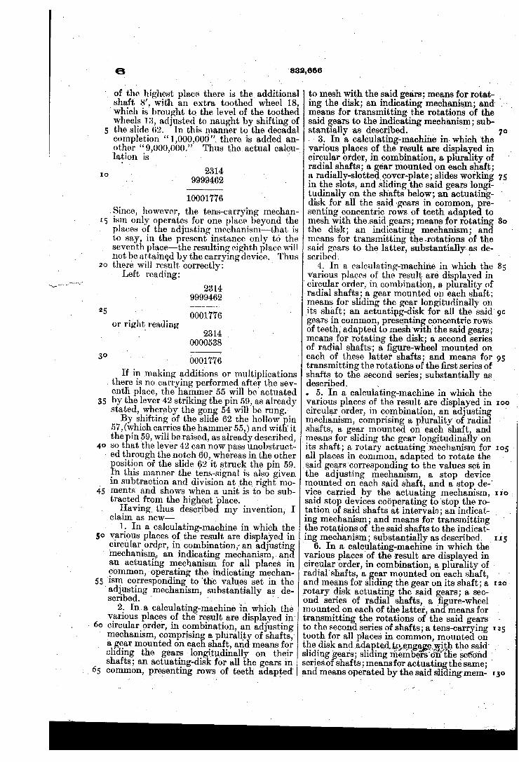
other “9,000,000.-” lation is
' ‘ 2314
9999462
10001776 .Since, however, the tens-carrying mechan ism only 0 crates for one place beyond the places of t e adjusting mechanism-that is to say, in the present instance only to the seventh place—the resulting eighth place will not be attained by the carrying device. Thus there will result correctly: '
Left reading: 2314
9999462
0001776 2314
0000538
or right reading
_ _ 0001776
If in making additions or multiplications . there is nocarrying performed after the sev enth place, the hammer 55 will be actuated by the lever-42 striking the pin 59, as already stated, whereby the gong 54 will be rung.‘ By shifting of the slide 62 the hollow in
57, (which carries the hammer 55,) and wit ' it the pin 59, will be raised, as already described, so t at the lever 42 can now pass unobstruct
» ed through the notch 60, Whereas in the other
45
55
osition of the slide 62 it struck the pin 59. _n this manner the tens-signal is also given in subtraction and division at the right mo ments' and shows when a unit is to be sub tracted from the highest ' lace. _ Having thus describe my invention, I
claim as new——- ‘
‘ 1. In a calculating-machine in which the various places of the result are displayed in clrculanorder, in combination; an adjustin mechanism, an indicating mechanism, an an actuating mechanism for all places in common, ‘operating the indicating mechan ism corresponding to 'the values set in the ad]usting mechanism, substantially as de scribed. ' ' _ _ _ "
2. Ina calculating-machine in Which the various places of the result are displayed in‘ circular order, in combination, an adjusting mechanism, comprisin a pluralit of shafts,‘ a gear mounted on eac shaft, an means for
' sliding the gears longitudinally on their shafts; an actuating-disk‘for all the gears inv common, presenting rows of teeth adapted‘
Thus the actual calcu-_
. sai
832,666
to mesh with the said gears; means for rotat- ‘
ing the disk; an indicating mechanism; and‘ means for transmitting the rotations of the said ears to the indicating mechanism; sub stantlally as described. _ ' Y
> - 3.- Ina calculating-machine in- which ‘the various places of the result are displa ed in circular order, in combination, a plura ity of radial shafts; a car mounted on each shaft; a radially-slotte _ vcover-plate ; slides working in the slots, and sliding the ‘said gears longi tudinally on the shafts below; an actuating- ' disk for all the said gears in common, ,re senting concentric rows of teeth adapte to mesh with thesaid gears; means for rotating the disk; an indicating mechanism; and means for transmitting the -rotations of the said gears to the latter, substantially as de scribed‘. '
4. In a calculating-machine in which the 85 various places of the result are displayed in
70
1,5
' circular order, in combination, a plurality of' radial shafts; a gear mounted on. each shaft; means for sliding the gear longitudinally on its shaft; an actuating-disk for all the said' gears in common, presenting concentric rows of teeth, adapted to mesh with the said gears; means for rotating the disk; a second series .of radial shafts; a ?gure-wheel mounted on each of these latter shafts; and means for 95 ‘transmitting the rotations of the ?rst series of shafts to the second series; substantially as. described. . '
. 5. In a calculating-machine in which the various places of the result are displayed in circular order, in combination, an adjustin mechanism, comprising a plurality ‘of radia shafts, a gear mounted on each shaft, and means for sliding the gear Iongitudinally'on
I00
its shaft; a rotary actuating mechanism for I05 ' all ‘places in common, adapted to rotate the
gears corresponding to the values set in the adjusting mechanism, a stop device mounted on each said shaft, and a stop de-' vice carried by the actuating mechanism, 110. said stop devices coéperating to stop the ro tation of said shafts at intervals; an indicat- I ing mechanism; and means for‘transmitting the rotations of the said shafts to the indicat ing mechanism; substantially as described. _
' 6. In a calculating-machine in which the various places of the result aredisplayed in circular ‘order, in combination, a plurality of radial'shafts, a car mounted on each shaft, and means for sfi rotary disk actuating the said gears; a sec ond series ‘of radial shafts, a ?gure-wheel mounted on each of the latter, and means for transmitting the rotations'of the said gears to the secondseries of shafts; a tens-carrying I 25 tooth for all places in common, mounted on the disk and ada tedtp?eyngagexyvith the said‘ sliding gears; sli' ing members-Len the second ' ‘ seriesof shafts; means for actuating the same; ' and means operated by the said sliding'mem- r 30
11-5
ding the gear on its shaft; a I 20

.10
Is
15
30
832,666
ber, whereby the tens- carrying tooth is caused to engage with the sliding gears; sub stantially as described. i
7.‘ In a calculating-machine in which the various places of. the result are displayed in circular ‘order, in combination, an adjusting mechanism, an indicating mechanism; a ro tary actuating mechanism for all places in common, operating the indicating mechan ism corresponding to the values set in the adjusting mechanism; and means for count ing the rotations of the actuating mechan ism, comprising a radial shaft, a gear on the same meshing with a tooth of the actuating mechanism, .a plurality of radial shafts, a ?gure~wheel mounted on each of these shafts, and means for transmitting the rotations of the said gear to one of the said latter radial shafts; substantially as described.v
various places‘ of the result are displayed in circular order, in combination, an adjusting mechanism, a plurality of shafts, a ?gure wheel on each shaft, means for operating these wheels corresponding to the values set ‘in the adjusting mechanism, a mutilated gear on each shaft, a disk presenting circu— larly-disposed groups of teeth adapted to mesh with the gears, and means for rotating the disk, substantially as described.
9. In a calculating-machine in which the various places of the result are displayed in circular order, in combination, an adjusting
' mechanism, an indicating mechanism, means
35
40
for operating the latterv corresponding to the values set in the adjusting mechanism, a ro tations-counting mechanism, a plurality of shafts and a ?gure-wheel on each shaft, a mu tilated gear on each shaft, a disk presenting circularly-disposed groups of teeth, adapted to mesh with the gears, and means for rotat
‘ ing the disk, substantially as described.
45
10. In a calculating-machine in which the various places of the result are displayed in circular order, in combination, an adjusting mechanism; an indicating mechanism and a rotations-counting mechanism and means for operating these two latter mechanisms, said indicating and counting mechanisms each possessing an equal number of ?gure wheels circularly disposed and alternating with each other; a case containing the said mechanisms, perforated at the ?gure-wheels; a perforated ring moving over the perfora tions in the‘, case, and means for rotating the
, ring through the distance between two adja cent case perforations; substantially as de scribed. ' ' '
11. In a calculating-machine in ‘which the various places of the result are displayed in circular order, in combination, a slotted case comprising two parts one of which can be ro tated-relatively to the other; a plurality of ra dial shafts 8' in one part of the case, a gear 13 on each shaft, located below a case-slot, a
8. In a calculating-machine in which the
‘transferring this
slide working in each slot and sliding one of ‘said gears on its shaft; a plurality of radial_ shafts 19 in the other art of the case, a ?g ure-wheel 20 on each atter shaft, a central shaft 6; a disk mounted on said shaft, pre senting concentric rows of teeth meshing with the gears 13 on the first said shafts 8; gears for transmitting the rotations of the - ?rst said shafts 8 to the second said shafts 19; a carrying-tooth mounted on the disk; means for-causing the said tooth to mesh with the ?rst said gears 13 ; a rotations-count ing mechanism actuated by the said disk and possessing a plurality of radial shafts 24lo cated between-the second said shafts 1.9, a ?gure-wheel ‘2.5 on each of the counting-mech anism shafts 24; and means for returning the said ?gure-wheels 20 and 25 to the 'ZBI‘O‘POSI tion; substantially as described. . -
12. In‘a calculating-machine in which th various places of the result are displayed in circular order, in combination, a plurality of shafts, a gear on each shaft and means for sliding the gears longitudinally on their shafts; a rotary disk gears; a second series of shafts, a ?gure wheel on each of the same, and means for transmitting the rotations of the said gears to the ?gure-wheels; a carrying-tooth carried by the said disk; means for causing the tooth to engage with the said gears; an audible sig nal located in the case, and means actuated by the carrying- tooth for operating the same, substantially as describer .
13. In a calculating—rnachine, in combina tion, an adjusting mechanism presenting for each place a group of.?gures, and a second group of ?gures located adjacent to the ?rst group‘ and so disposed that the figures of the second group are completed by the corre sponding ?gures of the ?rst group‘ through all places seriatim to the power of “10” cor responding to the number of the places; an indicating mechanism; means for transfer~ ring the, completion value introduced by the second group to the said indicating mechan ism; and means of enabling correct indica
or rotating the said '
75
85.
95
-4 (I ' o .
110
tion of the result thus in excess to the extent ' of the corresponding power of “ 10, ” substan tially as described. .
14. In a calculating-machine, in combina tion, an adjusting mechanism presenting for each place a group of ?gures and a second group of ?gures located adjacent to the ?rst group and so'disposed that the ?gures of the 'second group are completed by the corre-v s onding ?gures of the~ ?rst group through a 1 places seriatim to the power of “ 10” cor res onding to the number of the places; an in icating mechanism; a completing mech anism, located adjacent to the highest place of the adjusting mechanism whereby the value “9’ can be introduced; means for
entire value of the said indi cating mechanism; and means for. throwing
115
I20
125
IO
8..
the said completing mechanism into and out ’ of operation ;substantially as described.
_ 15. Inv a calculating-machine, in combina tlon, an adjusting mechanism, presenting for each place a group of ?gures and a second group of ?gures located adjacent to the ?rst group and so disposed that the ?gures of the second group are completed by the '_corre s onding ?gures of the ?rst group through a 1 places “mam to the power of ‘.‘ 10’,’ cor res onding to the number of the'places; an, -
' in icating mechanism; a completing mech
I5
anism located adjacent to the highest place of the adjusting mechanism whereby the value “9” can be introduced; means for, transferrin thisentire value to the said indi
. eating mec anism; means for throwing the
25
35
~ having ra
said completing vmechanism into and- out of :o eration;_' a carrying‘ mechanism for the
20 p aces of‘the indicating mechanism corre spondlng in number to those of the adjusting
‘ mechanism; an audible signal; means for ac tuatinggthe same by means of the carrying mechanism; and means for disengagingthe signal-operating mechanism; substantially as descrlbed. ‘
1 In a calculating-machine, in which the various places of the result are displayed in clrcular order, in combination, a pluralit of shafts, a gear on each shaft, a cover-p ate
'al slots and .presenting at each slot a group of ?gures 0—9 and a second group'of ?gureswadjacent to the ?rst and so disposed that the ?gures of the ‘second group are completed by the corresponding figures of the ?rst grou through all places sematim
, to the power 0 “'10” correspondingto the
40
50
number of the places; slides working in the cover-plate slots and sliding the gears _ on their shafts, a com letin mechanism located adjacent to the big est p ace of the adjusting mechanism whereby the value '“9” can be introduced, there being at the said complet ing mechanism'a shaft , a gear mounted there on and means for sllding the‘ gear on. its shaft; an indicating mechanism, means for rotating the ?rst said gears and the gear at the completing mechanism, corresponding to the values introduced and means for trans mitting the rotations of the said gears to the indicating mechanism; a tens-carrying mech anism for the places of the indicating mech
, anism _
- mechanlsm; substantially as describe
' Witnesses: - _ '
, HENRY HASPER, _
‘ WOLDEMAR
882,666
anism corresponding in number to those of the adjusting mechanism; an audible signal means for actuating the same b means of the tens-carrying; mechanism, an means for
s5 disenga ‘ing the said signal-operating mech .
y actuating the, said completing ‘17. In a calculating-machine in which the
variousplaces of the result are displayed in circular order, a lurality of radialshafts 8 a gear 13v on eac shaft, a cover-plate hav ing radial slots 7 and presenting at each‘ slot a group of ?gures 0-9 and a second group of ?gures adjacent to the ?rst and so disposed that the res of the second group are com ‘leted by the. corres onding?gures of the st group through a 1 places seriat'zm to the
power of ‘ 10 ” ‘corresponding to ‘the number of the laces, a slide 14 working in each cover-p ate slot 7 and sliding a gear 13 on
60'
65
75
its shaft 8; a supplementary shaft 8' lo- . cated adjacent to the highest place of the ad justing mechanism, a gear 18 on this shaft 8,’ above which the cover-plate has a'slot - 61, a slide 62 having an inclined face, working in this slot 61 and slidinglthe last said gear 18 ‘on its shaft; anlactuating-disk 28, having concentric rows oflt‘eeth' adapt 80 ed to engage-with and actuate on the said' ' gears 13, 18; means for rotating the disk; an indicating mechanism and means for trans- _ mitting the rotations of the said gears 13, 18 to the same; a carrying-tooth 42 on- the ac tuating-disk 28 and‘ means for causing this tooth to mesh with the said gears 13, 18;‘ a _ gong; an axis, a spring-c'tntrolled ‘bell-ham mer turning on and s idi g on the axis and having a notched projection lying in the path of the said carrying-tooth 42 but ordinarily allowin the latter to pass through the notch; and a ow hin ed to the case'of the ma chine, one end 0 whichrests on the inclined faced slid'e62 while the other end engages‘ with the boss 57 of the. said bell-hammer; substantially as described. ' ' - - "
In witness whereof I have hereunto set my ‘ hand in the presence of two witnesses.
' cHRrsrEL HAMANN.‘ '