Embed Size (px)
Citation preview
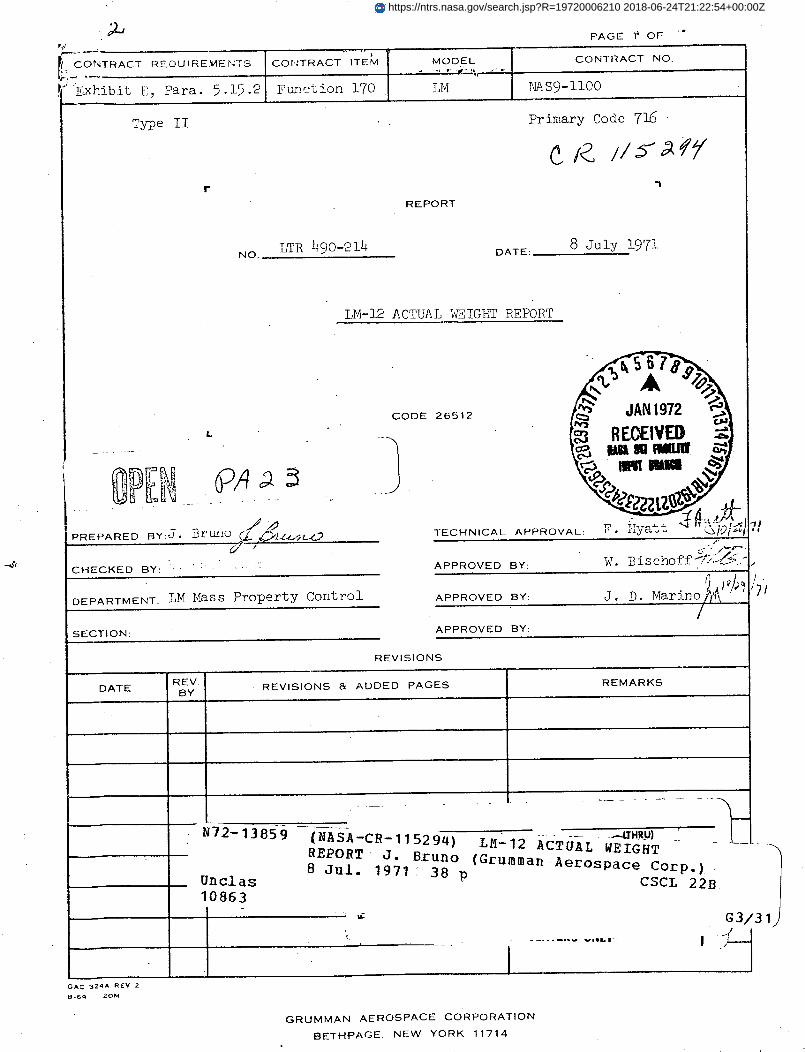
PAGE 'i' OF
CONTRACT REQUIREMEINTS CON'TRACT ITEM MODEL CONTRACT NO.
' Exhibit E, Para. 5.15.2 Function 170 LM ,LIAS9-1100
Type II Primary Code 716
rREPORT
NO. LTR 490-214 DATE: 8 July 1971
LM-12 ACTUAL WEIGHT REPORT
CODE 26512
L -REOQEIV
PREPARED EY:d, DI'Bx 10 _/ ,. TECHNICAL APPROVAL: X . I ya* . .
CHECKED BY: -- - - - APPROVED BY: W BYischoff: .-
DEPARTMENT: LM Mass Property Control APPROVED BY: J. D. Marino,
SECTION: APPROVED BY:
REVISIONS
DATE REV. REVISIONS & ADDED PAGES REMARKSBY
I N72--13859- (NASA-CR-11 -_.. -UJHRU)N72-13859 (NASA-CR-11529 4 ) LM-12 ACTUAL WEIGHT _
REPORT J. Bruno (Grumman Aerospace Corp.)8 Jul. 1971 38 pUnclas 8Jl191CSC 22.B."1 /"r r la
I -
I.
-I'U
ii
G3/3 1
yGAC 324A REV 2
8-69 20M
GRUMMAN AEROSPACE CORPORATION
BETHPAGE. NEW YORK 11714
f,)
/'1
I .·_ . vi i, r
1/
t_
https://ntrs.nasa.gov/search.jsp?R=19720006210 2018-06-24T21:22:54+00:00Z
PAG '- ii
I
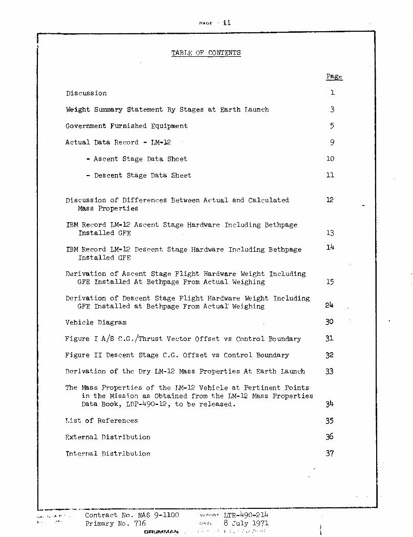
TABLE OF CONTENTS
Page
Discussion 1
Weight Summary Statement By Stages at Earth Launch 3
Government Furnished Equipment 5
Actual Data Record - LM-12 9
- Ascent Stage Data Sheet 10
- Descent Stage Data Sheet 11
Discussion of Differences Between Actual and Calculated 12Mass Properties
IBM Record LM-12 Ascent Stage Hardware Including BethpageInstalled GFE 13
IBM Record LM-12 Descent Stage Hardware Including Bethpage 14Installed GFE
Derivation of Ascent Stage Flight Hardware Weight IncludingGFE Installed At Bethpage From Actual Weighing 15
Derivation of Descent Stage Flight Hardware Weight IncludingGFE Installed at Bethpage From Actual Weighing 24
Vehicle Diagram 30
Figure I A/S C.G./Thrust Vector Offset vs Control Boundary 31
Figure II Descent Stage C.G. Offset vs Control Boundary 32
Derivation of the Dry LM-12 Mass Properties At Earth Launch 33
The Mass Properties of the LM-12 Vehicle at Pertinent Pointsin the Mission as Obtained from the LM-12 Mass PropertiesData Book, LDP-490-12, to be released. 34
List of References 35
External Distribution 36
Internal Distribution 37
-... . Contract No. NAS 9-1100 , ,-.l-m~ LTR-490-214.. . ..' Primary No. 716 t:r, 8 July 1971
GRUJMMAN . : ;: . .
II
PAC&G 1.~~~~~~~ac _
I
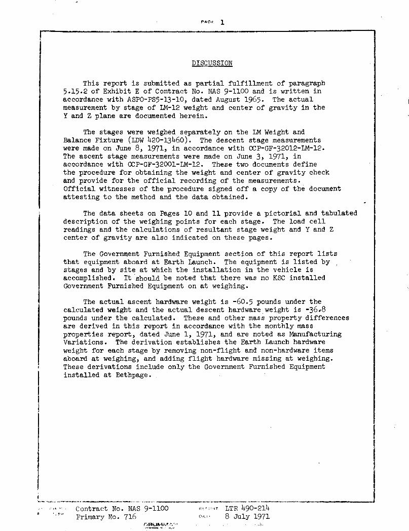
DISCUSSION
This report is submitted as partial fulfillment of paragraph5.15.2 of Exhibit E of Contract No. NAS 9-1100 and is written inaccordance with ASPO-PS5-13-10, dated August 1965. The actualmeasurement by stage of LM-12 weight and center of gravity in theY and Z plane are documented herein.
The stages were weighed separately on the LM Weight andBalance Fixture (LDW 420-13460). The descent stage measurementswere made on June 8, 1971, in accordance with OCP-GF-32012-LM-12.The ascent stage measurements were made on June 3, 1971, inaccordance with OCP-GF-32001-LM-12. These two documents definethe procedure for obtaining the weight and center of gravity checkand provide for the official recording of the measurements.Official witnesses of the procedure signed off a copy of the documentattesting to the method and the data obtained.
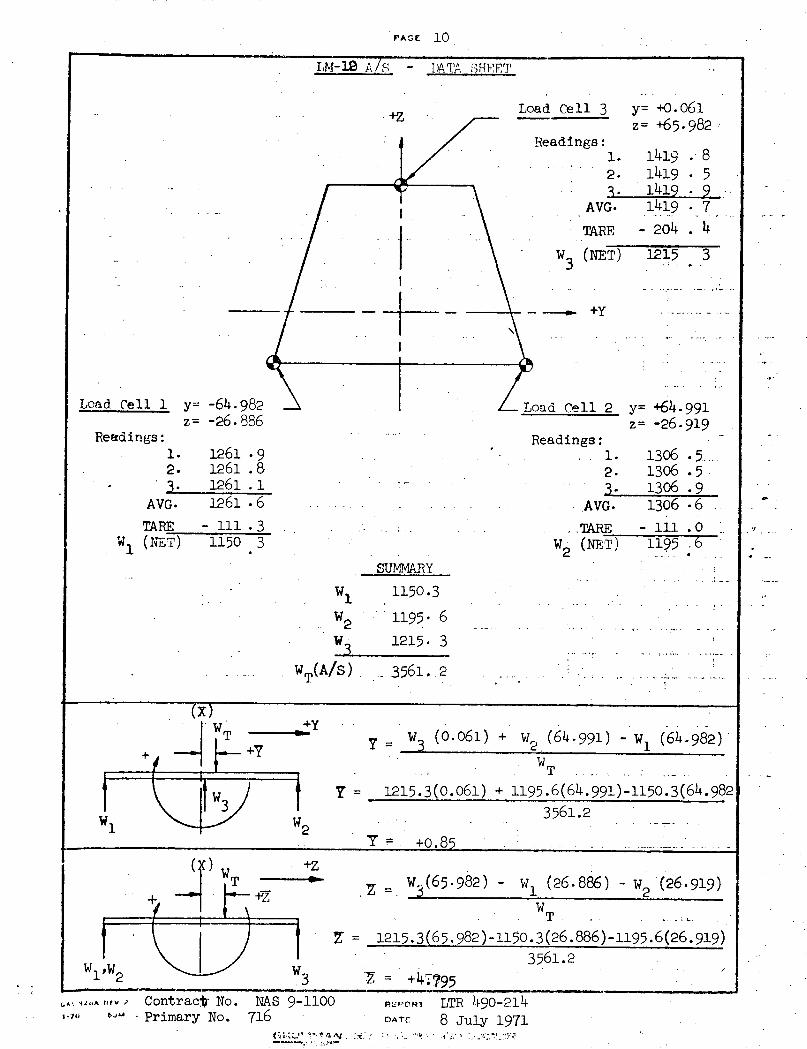
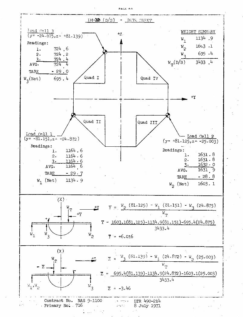
The data sheets on Pages 10 and 11 provide a pictorial and tabulateddescription of the weighing points for each stage. The load cellreadings and the calculations of resultant stage weight and Y and Zcenter of gravity are also indicated on these pages.
The Government Furnished Equipment section of this report liststhat equipment aboard at Earth Launch. The equipment is listed bystages and by site at which the installation in the vehicle isaccomplished. It should be noted that there was no KSC installedGovernment Furnished Equipment on at weighing.
The actual ascent hardware weight is -60.5 pounds under thecalculated weight and the actual descent hardware weight is -36,8pounds under the calculated. These and other mass property differencesare derived in this report in accordance with the monthly massproperties report, dated June 1, 1971, and are noted as ManufacturingVariations. The derivation establishes the Earth Launch hardwareweight for each stage by removing non-flight and non-hardware itemsaboard at weighing, and adding flight hardware missing at weighing.These derivations include only the Government Furnished Equipmentinstalled at Bethpage.
Contract No. NAS 9-1100 fi ~T LTR 490-2148 ' Primary No. 716 8 July 1971
.~RUM, 8 __ 1971
I
PAGE 2
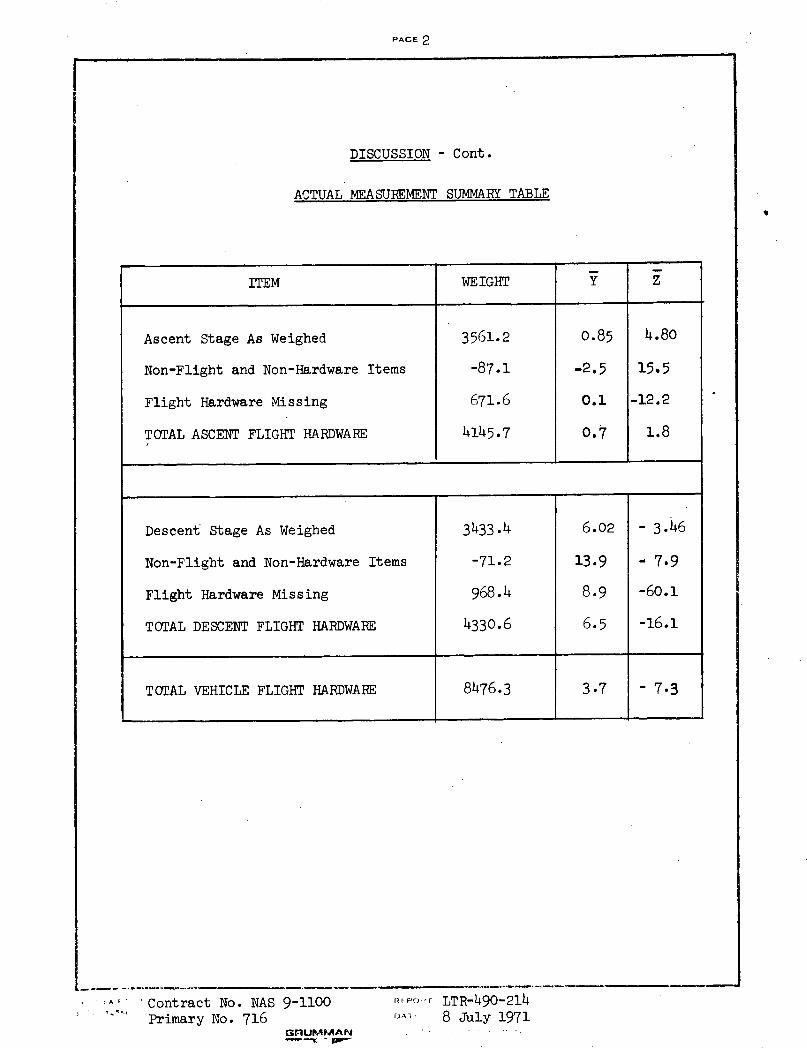
DISCUSSION - Cont.
ACTUAL MEASUREMENT SUMMARY TABLE
^ Al Contract No. NAS 9-1100Primary No. 716
GRFUMMAN ,
-Po·-- LTR-490-214
oA .: 8 July 1971
ITEM WEIGHT Y Z
Ascent Stage As Weighed 3561.2 0.85 4.80
Non-Flight and Non-Hardware Items -87.1 -2,5 15,5
Flight Hardware Missing 671.6 0.1 -12.2
TOTAL ASCENT FLIGHT HARDWARE 4145.7 0,7 1.8
Descent Stage As Weighed 3433.4 6.02 - 3.46
Non-Flight and Non-Hardware Items -71.2 13.9 7.9
Flight Hardware Missing 968.4 8.9 -60.1
TOTAL DESCENT FLIGHT HARDWARE 4330.6 6.5 -16.1
TOTAL VEHICLE FLIGHT HARDWARE 8476.3 3.7 - 7.3
PAGE 3--- -- - -- ~~~
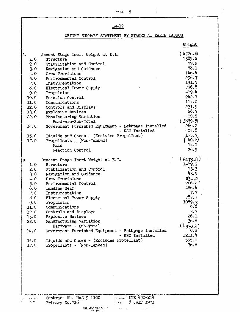
LM-12
WEIGHT SUMMARY STATEMENT BY STAGES AT EARTH LAUNCH
Weight
A. Ascent Stage Inert Weight at E.L. (4726.)1.0 Structure 1385.22.0 Stabilization and Control 79.23.0 Navigation and Guidance 78.14.0 Crew Provisions 146.45.0 Environmental Control 296.77.0 Instrumentation 131.58.0 Electrical Power Supply 736.89.0 Propulsion 469.410.0 Reaction Control 242.111. 0 Communications 114.012.0 Controls and Displays 231.913.0 Explosive Devices 28.722.0 Manufacturing Variation - 60.5
Hardware-Sub-Total (3879. 14.0 Government Furnished Equipment - Bethpage Installed 266.2
- KSC Installed 404.815.0 Liquids and Gases - (Excludes Propellant) 135.717.0 Propellants _ (Non-Tanked) (40.6)
Main 14.1Reaction Control 26.5
B. Descent Stage Inert Weight at E.L.1.0 Structure2.0 Stabilization and Control3.0 Navigation and Guidance4.0 Crew Provisions5.0 Environmental Control6.0 Landing Gear7.0 Instrumentation8.0 Electrical Power Supply9.0 Propulsion11.0 Communications12.0 Controls and Displays13.0 Explosive Devices22.0 Manufacturing Variation
Hardware - Sub-Total14.0 Government Furnished Equipment -
15.0 Liquids and Gases - (Excludes Prc17.0 Propellants - (Non-Tanked)
Bethpage InstalledKSC Installedopellant)
Contract No. NAS 9-1100Primary No. 716
f,0.I , !.1 LTR 490-214t AT! 8 July 1971
(6173X8)1469.913.343.5
234.2206.2486.47.7
787.31089.3
0.03.326.1
-36.8(4330.4)
0.21211.4555.076.8
K1 .I . AA _-
-- _ _ __-~ ̀ -- __---_ __I`.__-"_ .... ..-I- __··- - - -
j
II
P^B 4i m i m
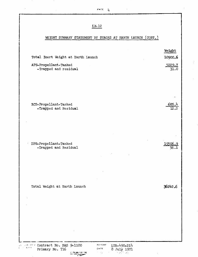
LM- 12
WEIGHT SUMMARY STATEMENT BY STAGES AT EARTH LAUNCH (CONT.)
Total Inert Weight at Earth Launch
APS-Propellant-Tanked-Trapped and residual
RCS-Propellant-Tanked-Trapped and Residual
DPS-Propellant-Tanked-Trapped and Residual
Total Weight at Earth Launch
L,. .... . ", Contract No. NAS 9-1100
Primary No. 716DF OTRT
DA TEI~:~ ftLTR-490-2148 July 1971
Weight
10900.6
5229.731.0
605.412.2
19506.956.1
36242.6
.~~- - _ -- v- .
PAGF5
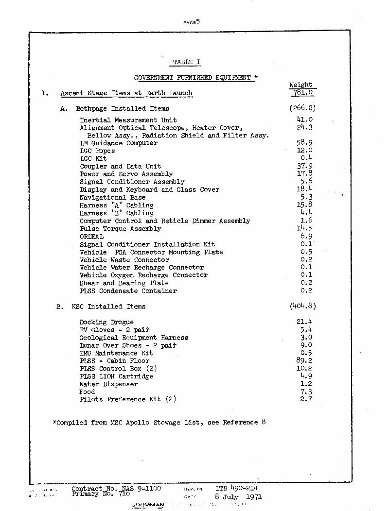
TABLE I
GOVERNMENT FURNISHED EQUIPMENT *Weight
1. Ascent Stage Items at Earth Launch 781.0
A. Bethpage Installed Items (266.2)
Inertial Measurement Unit 41.0Alignment Optical Telescope, Heater Cover, 24.3
Bellow Assy., Radiation Shield and Filter Assy.LM Guidance Computer 58.9LGC Ropes 12.0LGC Kit 0.4Coupler and Data Unit 37.9Power and Servo Assembly 17.8Signal Conditioner Assembly 5.6Display and Keyboard and Glass Cover 18.4Navigational Base 5.3Harness "A" Cabling 15.8Harness "B" Cabling 4.4Computer Control and Reticle Dimmer Assembly 1.6Pulse Torque Assembly 14.5ORDEAL 6.9Signal Conditioner Installation Kit 0.1Vehicle PGA Connector Mounting Plate 0.5Vehicle Waste Connector 0.2Vehicle Water Recharge Connector 0.1Vehicle Oxygen Recharge Connector 0.1Shear and Bearing Plate 0.2PLSS Condensate Container 0.2
B. KSC Installed Items (404.8)
Docking Drogue 21.4EV Gloves - 2 pair 5.4Geological EQuipment Harness 3.0Lunar Over Shoes - 2 pair 9.0EMU Maintenance Kit 0.5PLSS - Cabin Floor 89.2PLSS Control Box (2) 10.2PLSS LIOH Cartridge 4.9Water Dispenser 1.2Food 7.3Pilots Preference Kit (2) 2.7
*Compiled from MSC Apollo Stowage List, see Reference 8
,, Contract No. AS 9=1100 : LTR 490-214i Primary No. 71b t-o 8 July 1971
P,3tIMMAN : 1 P
F 1
PACGF 6- ---
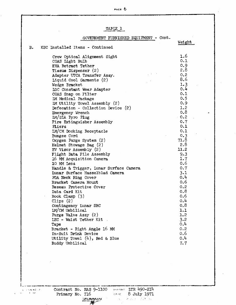
TABLE 1
GOVERNMENT FURNISHED EQUIPMENT - Cont.Weight
B. KSC Installed Items - Continued
Crew Optical Alignment Sight 1.6COAS Light Bulb 0.1EVA Retract Tether 0.9Tissue Dispenser (2) 2.8Adapter UTCA Transfer Assy. 0.2Liquid Cool Garments (2) 8.6Wedge Bracket 1.3LGC Constant Wear Adapter 0.4COAS Snap on Filter 0.1IM DMedical Package 0.5IM Utility Towel Assembly (2) 0.9Defecation - Collection Device (2) 1.2Emergency Wrench o.8LM4/SA Pyro Plug 0.2Fire Extinguisher Assembly 0.7Pliers 0.1LM/CM Docking Receptacle 0.1Bungee Cord 0.3Oxygen Purge System (2) 71.8Helmet Stowage Bag (2) 2.8EV Visor Assembly (2) 11.2Flight Data File Assembly 9.316 MM Acquisition Camera 1.710 MM Lens 0.6Handle & Trigger, Lunar Surface Camera 0.7Lunar Surface Hasselblad Camera 3.1PGA Neck Ring Cover 0.4Bracket Camera Mount o.6Reseau Protective Cover 0.2Data Card Kit 0.8Book Clamp (3) o.6Clips (2) 0.4Contingency Lunar SRC 0.8LM/CM Umbilical 1.1Purge Valve Assy (2) 1.2LEC - Waist Tether Kit 3.2Tape o.4Bracket - Right Angle 16 MM 0.2In-Suit Drink Device 0.6Utility Towel (4), Red & Blue 0.4Buddy Umbilical 7.7
·I alo ~ Contract No. NAS 9-1100 ,,,:,,; LTR 490-214Primary No. 716 i:·l: 8 July 1971
.Plmil.UMA . . I
S'epqf ' ::r·-'''
PAGE 7
TABLE 1
GOVERNMENT FURNISHED EQUIPMENT - Continued
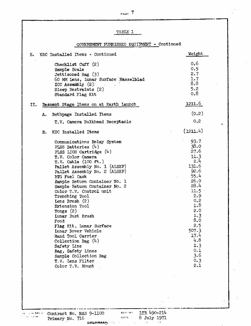
B. KSC Installed Items - Continued Weight
Checklist Cuff (2) 0.6Sample Scale 0.5Jettisoned Bag (3) 2.760 MM Lens, Lunar Surface iHasselblad 1.7ICC Assembly (2): 8.8Sleep Restraints (2) 5.2Standard Flag Kit o.8
II. Descent Stage Items on at Earth Launch 1211.6
A. Bethpage Installed Items (0.2)
T.V. Camera Bulkhead Receptacle 0.2
B. KSC Installed Items (1211.4)
Communications Relay System 93.7PLSS Batteries (4) 38.0PLSS LIOH Cartridge (4) 27.6T.V. Color Camera 11.3T.V. Cable (100 ft.) 2.4Pallet Assembly No. 1 (ALSEP) 131.6Pallet Assembly No. 2 (ALSEP) 92.6RTG Fuel Cask 55.4Sample Return Container No. 1 26.0Sample Return Container No. 2 28.4Color T.V. Control unit 11.5Trenching Tool 2.9Lens Brush (2) 0.2Extension Tool 1.8Tongs (2) 2.0Lunar Dust Brush 1.3Food 8.0Flag Kit, Lunar Surface 2.5Lunar Rover Vehicle 507.3Hand Tool Carrier 17.4Collection Bag (4) 4.8Safety Line 1.3Bag, Safety Lines 0.1Sample Collection Bag 3.6T.V. Lens Filter 0.3Color T.V. Mount 2.1
. ..tv. Contract No. NAS 9-1100 RE:!':FI LTR 490-214. ..'M Primary No. 716 ,A^,T. 8 July 1971
GRUPLIMAN : . i
PAGE 8i! i , i i~~~,
TABLE 1
GOVERNMENT FURNISHED EQUIPMENT - Continued
Weight
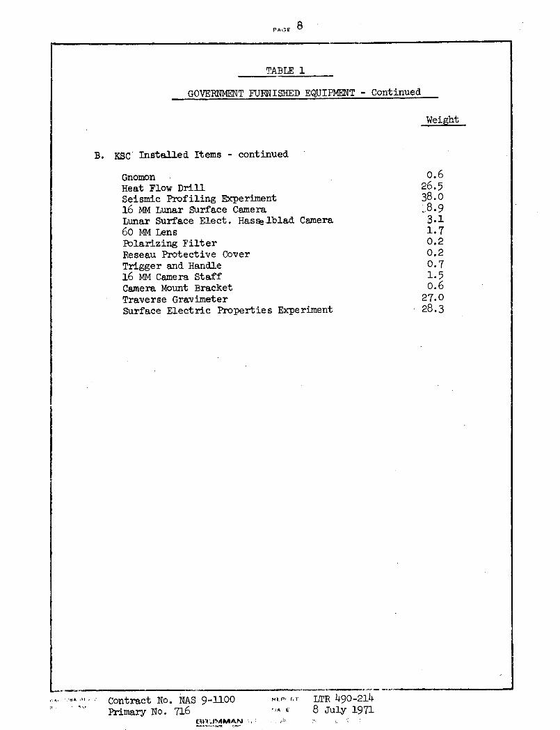
B. KSC Installed Items - continued
GnomonHeat Flow DrillSeismic Profiling Experiment16 MM Lunar Surface CameraLunar Surface Elect. Hasse.lblad Camera60 MM LensPolarizing FilterReseau Protective CoverTrigger and Handle16 MM Camera StaffCamera Mount BracketTraverse GravimeterSurface Electric Properties Experiment
Contract No. NAS 9-1100Primary No. 716
Chp NlMMAN t-
HP, FT LTR 490-214!^A E 8 July 1971
0.626.538.018.93.11.70.20.20.71.50.627.028.3
.k .. ;1H . .
.1 I "...
_
PAGE 9
DATA SHEETS
The following two pages show the data obtained from the
Ascent Stage and Descent Stage OCP's and the calculation of the
total stage weight and center of gravity. The original data is
on the Grumman Q.C. hard copy in the Q.C. permanent files.
I.... 0,.REvContract No. NAS 9-8 ") 12"' Primary No. 716
-1100 FE,,oR-.TR- 490- 214
OA Ii. 8 July 1971GRnulMI A~' !' 4.''':..", 'i:. '.a::':T. ,,''. .: ; ;,!
4
PAGE 10
!,Mr-1. A/s- SATH T -
Load Cell 3 y= +0.061+Z - z= +65.982
: eadings:1. 1419.82 . 1419 · 5
AVG. 1419 7
TARE -2o04
w (NET) 1215 3
. /......3' .
Load Cell 1 y= -64.982 / Load Cell 2 y= +64.991z= -26. 886 z= -26.919
Reeadings: Readings: -1. 1261 .9 ' . 1. 1306 .5.
2. 1261 .8 2. 1306 .53. 1261 .1 3. 1306 .9
AVG. 1261 .6 AVG. 1306 .6
TARE -111.3 ... : .AR -111 .0W1 (I.T) 1150 3 W2 (NIjT) 1195 6
SUMMARY
wl 1150.3 ,
W2 - 1195. 6
W- 1215. 3
WT(A/S) 3561 .2. '
wF
y _- w = W3 (0.061) + w2 (64.991) - Wi (64.982)-I T +Y O 061 w 64 6 WT..
7 ' = 1215.3(0.061) + 1195.6(64.991)-1150.3(64.982
3561.2
W1 W2- ...........................Y .+o.85
"+ -)1' ~;W-.Z= w3(65-982) - W1 (26.886) - w2 (26.919)
T
Z 1215.3(65.982)-1150.3(26.886)-1195.6(26.919)3561.2
Wl'W2 W3 7 +4495
.A. ~.--r Contractb No. NAS 9-1100 --c'0n LTR 490-2141-I o JM Primary No. 716 - AT 8 July 1971
PA-,; 4--
_.M--2 (D/S) - D '
Toaid 1'ell 3(y= -24.b85,z= +81.139)
Readings:
1. 724 .62. 724 .23. 724 .4
AVG. 724 4
TARE - 29. 0
W3(Net) 695. 4
ioad (Tell 1
(y= -81.151,z- -24.872 )
Readings:1. 1164. 62. 1164. 6
3' 1164. 6AVG. 1164 6
TARE - 29. 7
W1 (Net) 1134. 9
WEIGEHT SuMiK"RY
W1 1134 .9
W2 1603 .1
W 695 .43
3433 .4
\-- Load Cell 2(y= +81.125,z= -25.003)
Readings:1. 1631. 82. 1631. 8
.. 1632. 0AVG. 1631 9
TARE - 28. 8
W, (Net) 1603. 1
'(X) ·
T Y Y ' w2 (81.125) - 1 (81.151) - W3 (24.875)
_ T _+WT
Y = 1603.1(81.125)-1134.9(81.151)-695.4(24.875)
3433.4
2 \~ = +6.016
(X)
J Y .
Contract No.I· .. . Primary No.
--7
lo
, a_-- j .
IW
3
= W (8l.-139i - W (24.872) - W2
(25.003)
Z = 695.4(81.139)-1134.9(24.872)-1603.1(25.003)
3433.4
Z --3.46
NAS 9-1100 .i I LTR 490-214716 .. : 8 July 1971
I
I
T--
Iii
?
PAGE 12
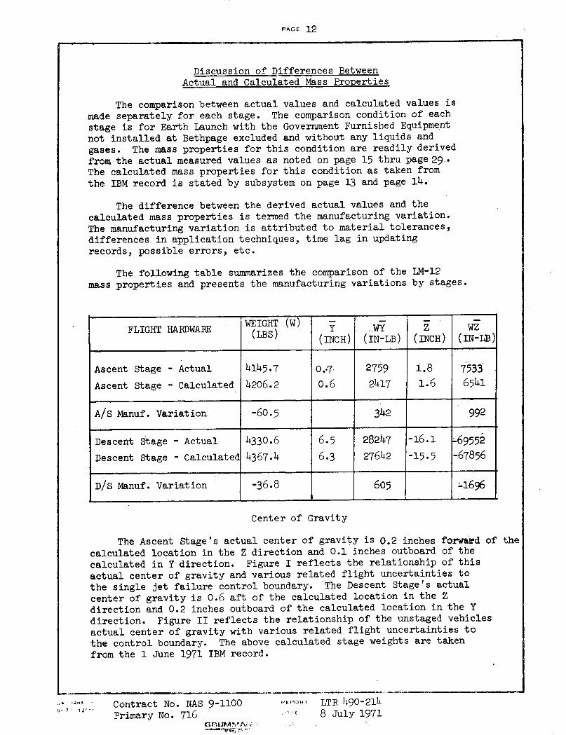
Discussion of Differences BetweenActual and Calculated Mass Properties
The comparison between actual values and calculated values ismade separately for each stage. The comparison condition of eachstage is for Earth Launch with the Government Furnished Equipmentnot installed at Bethpage excluded and without any liquids andgases. The mass properties for this condition are readily derivedfrom the actual measured values as noted on page 15 thru page 29..The calculated mass properties for this condition as taken fromthe IBM record is stated by subsystem on page 13 and page 14.
The difference between the derived actual values and thecalculated mass properties is termed the manufacturing variation.The manufacturing variation is attributed to material tolerances,differences in application techniques, time lag in updatingrecords, possible errors, etc.
The following table summarizes the comparison of the LM-12mass properties and presents the manufacturing variations by stages.
Center of Gravity
The Ascent Stage's actual center of gravity is 0.2 inches forward of thecalculated location in the Z direction and 0.1 inches outboard of thecalculated in Y direction. Figure I reflects the relationship of thisactual center of gravity and various related flight uncertainties tothe single jet failure control boundary. The Descent Stage's actualcenter of gravity is 0.6 aft of the calculated location in the Zdirection and 0.2 inches outboard of the calculated location in the Ydirection. Figure II reflects the relationship of the unstaged vehiclesactual center of gravity with various related flight uncertainties tothe control boundary. The above calculated stage weights are takenfrom the 1 June 1971 IBM record.
A .2... ' Contract No. NAS 9-1100Primary No. 716
TiFr-UPIAN's!_vql *tr-
ItkPOH1 LTR 490-214... f 8 July 1971
WEIGHT (W)FLIGHT HARDWARE WEIGHT ..WY Z WZ(LBS) (INCH) (IN-LB) (INCH) (IN-LB)
Ascent Stage - Actual 4145.7 0.7 2759 1 .8 7533Ascent Stage - Calculated 4206.2 0.6 2417 1.6 6541
A/S Manuf. Variation: -60.5 342 992
Descent Stage - Actual 4330.6 6.5 28247 -16.1 -69552
Descent Stage - Calculated 4367.4 6.3 27642 -15.5 -67856
D/S Manuf. Variation -36.8 605 -1696
I
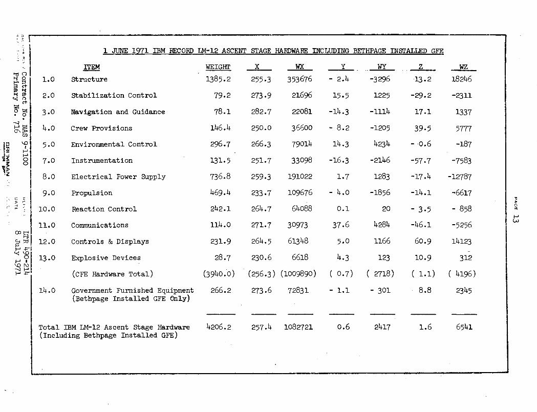
1 JUNE 1971 IBM RECORD LM-12 ASCENT STAGE
ITEM
1.0 Structure
2.0 Stabilization Control
3.0 Navigation and Guidance
4.0 Crew Provisions
5.0 Environmental Control
7.0 Instrumentation
8.0 Electrical Power Supply
9.0 Propulsion
10.0 Reaction Control
11.0 Communications
12.0 Controls & Displays
13.0 Explosive Devices
(CFE Hardware Total)
14.0 Government Furnished Equipment(Bethpage Installed GFE Only)
Total IBM LM-12 Ascent Stage Hardware(Including Bethpage Installed GFE)
WEIGHT
1385.2
79.2
78.1
146.4
296.7
131.5
736.8
469.4
242.1
114.0
231.9
28.7
(3940.0)
266.2
4206.2
X
255.3
273.9
282.7
250.0
266.3
251.7
259.3
233.7
264.7
271.7
264.5
230.6
(256.3)
273.6
HARDWARE INCLUDING BETHPAGE INSTALLED GFE
wx
353676
21696
22081
36600
79014
33098
191022
109676
64088
30973
61348
6618
(1009890)
72831
257.4 1082721
Y
- 2.4
15.5
-14.3
- 8.2
14.3
-16.3
1.7
- 4.0
0.1
37.6
5.0
4.3
( 0.7)
- 1.1
0.6
WY
-3296
1225
-1114
-1205
4234
-2146
1283
-1856
20
4284
1166
123
( 2718)
- 301
2417
Z
13.2
-29.2
17.1
39.5
- 0.6
-57.7
-17.4
-14.1
- 3.5
-46.1
60.9
10.9
( 1.1)
- 8.8
1.6
4 0r'
*0
I',
.
C -4
-t-
0\, O)
WZ
18246
-2311
1337
5777
-187
-7583
-12787
-6617
- 858
-5256
14123
312
( 4196)
2345
6541
o
nV
'n
H
_ · I _ __ __ 11
I
I
II
i
I
r
I.i
r
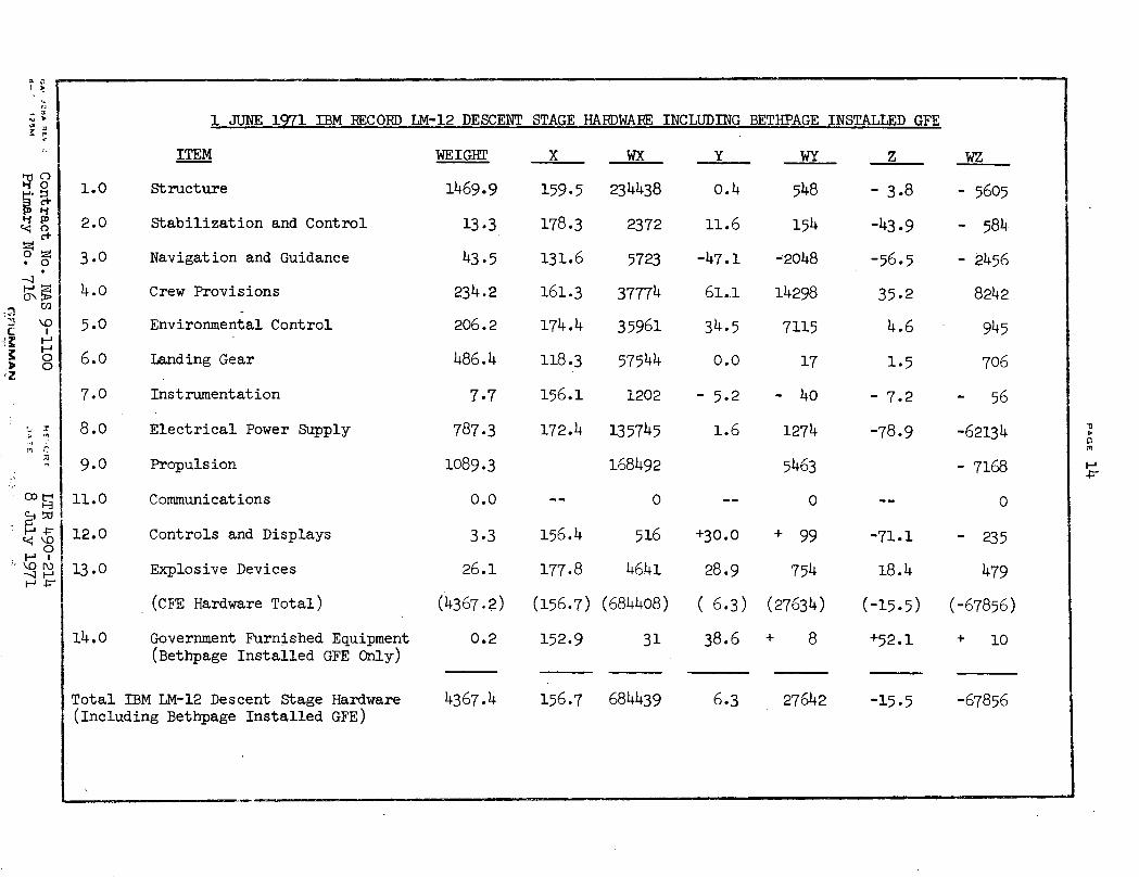
1 JUNE 1971 IBM RECORD LM-12 DESCENT STAGE HARDWARE INCLUDING BETHPAGE INSTALLED GFE
ITEM
Structure
Stabilization and Control
Navigation and Guidance
Crew Provisions
Environmental Control
Landing Gear
Instrumentation
Electrical Power Supply
Propulsion
Communications
Controls and Displays
Explosive Devices
(CFE Hardware Total)
Government Furnished Equipment(Bethpage Installed GFE Only)
WEIGHT
1469.9
13.3
43.5
234.2
206.2
486.4
7.7
787.3
1089.3
0.0
3.3
26.1
(4367.2)
0.2
X WX
159.5 234438
178.3 2372
131.6 5723
161.3 37774
174.4 35961
118.3 57544
156.1 1202
172.4 135745
168492
-- 0
156.4 516
177.8 4641
(156.7) (684408)
152.9 31
Total IBM LM-12 Descent Stage Hardware(Including Bethpage Installed GFE)
4367.4 156.7 684439 6.3 27642 -15.5 -67856
-z.,
0222
* O
OD
'o
r!
I-- .F- -PI
1.0
2.0
3.0
4.0
5.0
6.0
7.0
8.0
9.0
11.0
12.0
13.0
14.0
Y
0.4
11.6
-47.1
61..1
34.5
0.0
- 5.2
1.6
+30.0
28.9
( 6.3)
38.6
WY
548
154
-2048
14298
7115
17
- 40
1274
5463
0
+ 99
754
(27634)
+ 8
z
- 3.8
-43.9
-56.5
35.2
4.6
1.5
- 7.2
-78.9
-71.1
18.4
(-15.5)
+52.1
WZ
- 5605
- 584
- 2456
8242
945
706
- 56
-62134
- 7168
0
- 235
479
(-67856)
+ 10
H-P
I
III
L.
I
II
I
I i
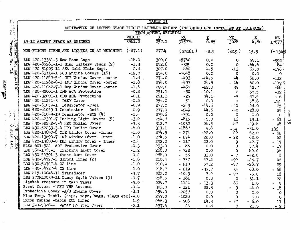
TABLE II
_~ 2 DERIVATION OF ASCENT STAGE FLIGHT HARDWARE WEIGHT (INCLUDING GFE INSTAT.TED AT BETHPAGE): I FROM ACTUAL WEIGHING
WEIGHT X WX Y WY Z WZIM-12 ASCENT STAGE AS WEIGHED 3561.2 257.1 915714 0.85 3028 4.80 17077
m '1 NON-FLIGHT ITEMS AND LIQUIDS ON AT WEIGHING (-87.1) 277.4 (-4161) -2.5 (919.) 15..5 (-134
L LDW 420-13361-3 Nav Base Gage -18.0 320.0 -5760 0.0 0 55.1 -992o ? LDW 420-83281-1-1 Sim. Battery Studs (2) -1.3 252.6 -38 0.0 0 -64.6 84
-~ LDW 420-51009-11 ASA Cold Plate Supt. -2.8 307.0 -860 4.5 -13 63.0 -17654 LDW 420-63119-1 RCS Engine Covers (16) -12.0 254.0 -3048 0.0 0 0.0 0LDW 420-11282-5-1 CDR Window Cover -outer -1.8 274.0 -493 -24.5 44 62.0 -112LDW 420-11282-6-1 LMP Window Cover -outer -1.8 274.0 -493 24.5 - 44 62.0 -112
o LDW 420-11282-7-1 Dkg Window Cover -outer -1.6 292.0 -467 -22.0 35 42.7 · -68LDW 420-32001-1 IMP ACA Protection -0.2 251.1 -50 -10.1 2 57.5 -12LDW 420-32001-1 CDR ACA Protection -0.1 251.1 -25 34.1 -3 57.5 - 6LDW 420-11251-3 DSKY Cover -0.2 254.0 -51 0.0 0 58.6 -12LDW 420-61059-1 Dessicator -Fuel -0.9 277.0 -249 -44.6 40 -28.0 25LDW 420-61059-1 Dessicator - Oxid -0.9 277.0 -249 44.6 -40 -28.0 25LDW 420-61049-19 Dessicator -RCS (4) -1.4 279.6 -391 0.0 0 0.0 0LDW 420-42301-7 Docking Light Covers (5) -3.2 254.7 -815 -5.0 16 19.1 - 61LDW 430-52232-5-4 H20 Boiler Cover -3.3 312.7 -1032 26.5 -87 -29.8 98LDW 430-52233-3-4 H20 Boiler Cover -6.0 311.1 -1867 9.8 -59 -31.0 186
C LDW 420-13690-8 CDR Window Cover -Inner -1.0 274.5 - 274 -22.0 22 62.0 - 62o LDW 420-13690-7 LMP Window Cover- Inner -1.0 274.5 - 274 22.0 - 22 62.0 - 62
H o LDW 420-13690-9 Dkg Window Cover - Inner -0.4 292.0 - 117 -22.0 9 42.7 - 17<- F |NASA 6014322 AOT Protective Cover -0.3 293.0 - 88 0.0 0 57.4 - 17
LSK 560-1065-1 Tracking Light Cover -1.2 268.0 - 322 0.0 0 80.0 - 96LDW 430-54391-3 Steam Duct Cover -0.2 288.0 - 58 33.0 - 7 -42.0 8LDW 430-54727-3 Glycol Lines (2) -1.6 210.4 - 337 57.2 -92 -28.7 46LDW 430-54727-4 02 Line -1.0 210.4 - 210 57.2 -57 -28.7 29LDW 430-54727-4 02 Line -1.0 218.7 - 219 -33.7 34 68.0 - 68LDW 815-10046-11 Transducer -3.7 282.0 -1043 7.2 - 27 -5.0 18LDW 270M10039-11 Dummy Squib Valves (9) -0.7 258.5 - 181 0.0 0 - 31.1 22Blanket Pressure in Main Tanks -5.0 224.7 -1124 - 13.3 66 1.0 - 5Strut Covers -' AFT VHF Antenna -0.4 303.0 - 121 22.3 - 9 44. - 18Protective Cover -A/S Engine Cover -8.1 254.0 -2057 0.0 0 0.0 OMisc Temp. Instl. (caps, tape, bags, flags etc)-4.0 257.0 -1028 0.0 0 0.0 0Tygon Tubing -Cabin ECS Lines -1.9 266.3 - 506 14.3 - 27 - 6.0 11LDW 340-53264-1 Water Holster Cover -0.1 237.6 - 24 - 0.8 0 21.5 - 2
U-- ~ ----- -- x-~.8
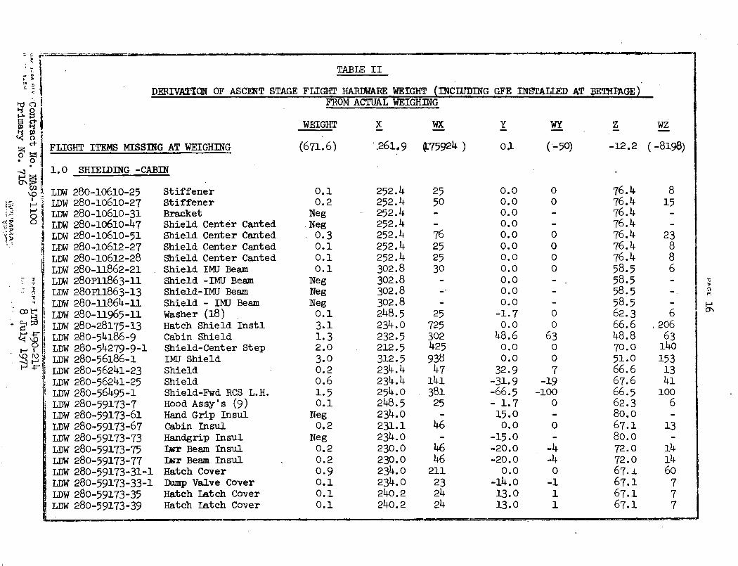
TABLE II
DERIVATION OF ASCENT STAGE FLIGHT HARDWARE WEIGHT (INCWDING GFE INSTATTRD AT BETHPAGE)FROM ACTUAL WEIGHING
WEIGHT
FLIGHT ITEMS MISSING AT WEIGHING (671.6)
X WX
.261.9 Q75924 )
y WY
o0 (-50)
z WZ
-12.2 (-8198)
1.0 SHIELDING -CABIN
280-10610-25 Stiffener280-10610-27 Stiffener280-10610-31 Bracket280-10610-47 Shield Center Canted280-10610-51 Shield Center Canted280-10612-27 Shield Center Canted280-10612-28 Shield Center Canted280-11862-21 Shield IMU Beam280P11863-11 Shield -IMU Beam280P11863-13 Shield-IMU Beam280-11864-11 Shield - IMU Beam280-11965-11 Washer (18)280-28175-13 Hatch Shield Instl280-54186-9 Cabin Shield280-54279-9-1 Shield-Center Step280-56186-1 IMU Shield280-56241-23 Shield280-56241-25 Shield280-56495-1 Shield-Fwd RCS L.H.280-59173-7 Hood Assy's (9)280-59173-61 Hand Grip Insul280-59173-67 Cabin Insul280-59173-73 Handgrip Insul280-59173-75 Iur Beam Insul280-59173-77 Imr Beam Insul280-59173-31-1 Hatch Cover280-59173-33-1 Dump Valve Cover280-59173-35 Hatch Latch Cover280-59173-39 Hatch Latch Cover
0.10.2NegNeg0.30.10.10.1NegNegNeg0.13.11.32.03.00.20.61.50.1
Neg0.2
Neg0.20.20.90.10.10.1
252.4252.4252.4252.4252.4252.4252.4302.8302.8302.8302.8248.5234.0232.5212.5312.5234.4234.4254.0248.5234.0231.1234.0230.0230.0234.0234.0240.2240.2
2550
76252530
25725302425938
4714138125
46
4646211
232424
0.00.00.00.00.00.00.00.00.00.00.0
-1.70.0
48.60.00.032.9
-31.9-66.5- 1.715.00.0
-15.0-20.0-20.0
0.0-14.013.013.0
00
0000
00
63007
-19-100
0
0
-4-40
-111
76.476.476.476.476.476.476.458.558.558.558.562'.366.648.870.051.066.667.666.562.380.067.180.072.072.067.167.167.167.1
815
23886
620663
1401531341
1006
13
141460
777
i-
! 0
Ot
1\O '
O
\o r
LDWLDWLDWLDWLDWLDWLDWLDWLDWLDWLDWLDWLDWLDWLDWLDWLDWLDWLDWLDW
iLDWLDW
ILDWLDWLDWLDWLDWLDW
-VCT
I
�-i--i�-=-n�----�--5D1 -- ·---- -- -- ----- -- --- -- ---- -- r -------- ·l-�-C�'� -C-
II
Ir
Ii
L
i,I
Ii
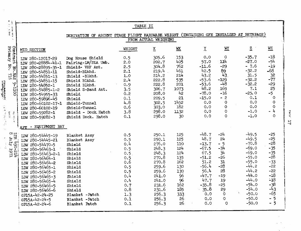
TABLE II
DERIVATION OF ASCENT STAGE FLIGHT HARDWARE WEIGHT (INCLUDING GFE INSTALLED AT BETHPAGE)FROM ACTUAL WEIGHING
MID SECTION
280-12017-29280-28884-41-1280-28895-35-1280-54851-11280-54851-13280-54851-15280-54852-1280-54885-1-2280-54955-33280-59896-45280-60102-17-1280-60102-19280-59282-1280-59282-3
Dog House ShieldFairing-LM/SLA Umb.Shield- VHF Ant.Shield-Blkhd.Shield -Blkhd.Shield Blkhd.Shield Blkhd.Shield S-Band Ant.ShieldShieldShield-TunnelShield-TunnelShield - Dock. HatchShield Dock. Hatch
- EQUIPMENT BAY
280-54445-19280-54445-21280-54470-5280-56463-1280-56463-2-1280-56464-1280-56464-2280-56465-1280-56465-2280-56465-3280-56465-4280-56466-5280-56466-6
GP15A-42-24-25GP15A-42-24-5GP15A-42-24-6
Blanket AssyBlanket AssyShieldShieldShieldShieldShieldShieldShieldShieldShieldShieldShieldBlanket -PatchBlanket -PatchBlanket Patch
WEIGHT
LDWLDWLDWLDWLDWLDWLDWLDWLDWLDWLDWLDWLDWLDW
WX Y i
1!
0
:3
o~v
g oM
ci-*01
.- ,
-~ I
0:
Z !)kOr.
-m1
0.52.02.52.11.02.40.93.50.20.14.80.63.80.1
X
305.6202.7304.8219.4214.2222.8222.8306.7208.0209.5302.5303.0298.0298.0
153405762461214535201
10734221
1452182
113230
0.057.0
-11.642.543.2-53.6-53.648.2
-78.0-15.00.00.00.00.0
WY
0114-298943
-129-48169-16-20000
z
-35.7-27.0- 7.6-32.231.5-32.2-32.27.1
-25. 00.10.00.0-1.0-1.0
WZ
-18-54-19-6832
-77-2925
-5000
-40
LDWLDWLDWLDWLDWLDWLDWLDWLDWLDWLDWLDWLDW
D
0.50.50.40.50.50.50.60.50.50.40.40.70.81.30.10.1
250.1250.1276.0248.3248.3270.8270.8259.6259.6241.0241.0231.6231.6256.3256.3256.3
1251251101241241351621301309696
1621853332626
-48.748.7-13.7-67.567.5-51.251.2-56.456.4-47.747.7-35.835.80.00.00.0
-2424
-5-3434
-2631
-2828
-1919
-2529ooo
-49.5-49.5-70.8-69.0-69.0-55.0-55.0-44.2-44.2-44.0-44.0-54.o-54.0-50.0-50.0-50.0
-25-25-28-35-35-28-33-22-22-18-18-38-43-65-5-5
I ------ -
¢
al 4
<
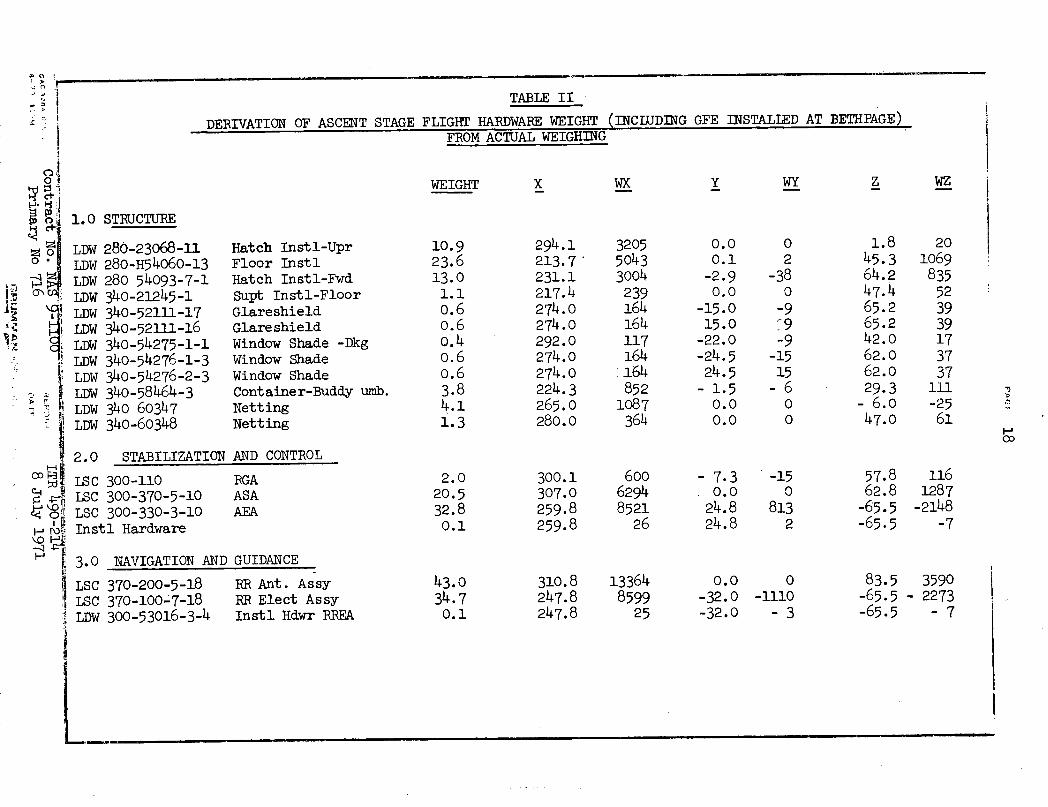
TABLE II
DERIVATION OF ASCENT STAGE FLIGHT HARDWARE WEIGHT (INC LUDING GFE INSTALLED AT BETHPAGE)FROM ACTUAL WEIGHING
WEIGHT X Wx Y WY
1.0 STRUCTURE
280-23068-U1280-H54060-13280 54093-7-1340-21245-1340-52111-17340-52111-16340-54275-1-1340-54276-1-3340-54276-2-3340-58464-3340 60347340-60348
Hatch Instl-UprFloor InstlHatch Instl-FwdSupt Instl-FloorGlareshieldGlare shieldWindow Shade -DkgWindow ShadeWindow ShadeContainer-Buddy umb.NettingNetting
10.923.613.01.10.60.6o.40.60.63.84 .11.3
294.1213.7231.1217.4274.0274.0292.0274.0274.0224.3265.0280.0
320550433004239164164117164:164852
1087364
0.00.1
-2.90.0
-15.015.0
-22.0-24.524.5
-1.50.00.0
02
-380
-9?9-9
-1515
-600
1.845.364.247.465.265.242.062.062.029.3
- 6.047.0
2.0 STABILIZATION
LSC 300-110LSC 300-370-5-10LSC 300-330-3-10Instl Hardware
AND CONTROL
RGAASAAEA
3.0 NAVIGATION AND GUIDANCE
LSC 370-200-5-18LSC 370-100-7-18LDW 300-53016-3-4
RR Ant. AssyRR Elect AssyInstl Hdwr RREA
I-
ILDWLDWLDWLDWLDWLDWLDWLDWLDWLDWLDWLDW
z
I
It
I
I
co t4 t
r_\OH110I 4
WZ
201069
835523939173737111-2561
2.020.532.80.1
300.1307.0259.8259.8
'3
6006294852126
- 7.3. 0.024.824.8
CHCC)
-150
8132
43.034.70.1
57.862.8
-65.5-65.5
1161287
-2148-7
310.8247.8247.8
13364859925
0.0-32.0-32.0
0-1110-3
83.5-65.5-65.5
3590- 2273
- 7
I
tX o,
, ,
.
. I
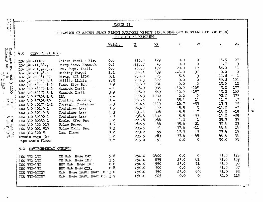
TABLE II
DERIVATION OF ASCENT STAGE FLIGHT HARDWARE WEIGHT (INCIUDING GFE INSTALLED AT BETHPAGE)FROM ACTUAL WEIGHING
Weight X WX Y WY Z WZ
4.0 CREW PROVISIONS
4 ~ LDWLDW
LDW*~ LDW
; mO i LDW°~ >^oLDWM
T LDW; LDWo LDW
LDW
i LDWLDWOD , LDW
LDWrH-i LSCDW
o LSCLSCLSC
340-11102340-11366-7340-21374-3-7340-51298-5340-52261-27340-53053-3-6340-53444-1-2340-56272-1-2340-56272 -3-1340-57303-1-3340-57303-39340-60175 -1-2340-60189-1340-60189-3340-60190-1340-60632-1340-100-019340-201-529340-406-5
Emesis Bags (6)Tape Cabin Floor
Velcro Instl - Flr.Strap Assy. HammockCam. Supt. Instl.Docking TargetStrap, ECS LIOHUtility LightsTemp. Stow Bag:Hammock InstlHammock InstlISAConting. WebbingCoverall ContainerContainer AssyContainer AssyContainer AssyEquip. Xfer BagUrine Recep.Urine Coll. Bag.Lum. Discs
5.0 ENVIRONMENITAL CONTROL
330-130330-130330-430330-430330-60027330-60027
02 Umb. Hose Cdr.02 Umb. Hose IMPH20 Umb. Hose LMPH20 Umb Hose CDR.Umb. Hose Instl HwdrUmb. Hose Instl Hwdr
, r
Xi
,
!°
.'ii
Ii
o.60.20.62.10.12.30.94.13.96.40.45.90.51.36.01.20.60.30.21.20.7
215.0.225.7286.0304.1250.0270.3257.0228.0228.0270.3231.5240.5243.7235.4238.6221.8242.5235.5273.2235.5215.0
12945
17263925
622231935889
173093
1419122306
14322661467155283151
0.00.0
20.0-46.0
8.80.00.0
-40.2-40.2
0.035.4
-16.7-5.5-5.5-5.5-1.0-35.6-37.6-17.3-37.6
0.0
0012-97
900
-165-157
014
-99-3-7-33-1
-21-11
-3- 45
0
45.544.768.00.0
-11.852.813.643.243.252.841.713.3
-14.8-14.8-14.829.538.646.675.446.650.0
279410
- 11211217716833817,78-7
-19-89352314155635
H
LSCLSCLSCLSCLDWLDW
5.63.52.22.8
ILMP 3.0CDR 3.7
250.0250.0250.0250.0250.0250.0
1400875550700750925
0.023.023.00.023.00.0
081510
69:0
31.031.031.031.o31.031.0
174.lo09688793
115
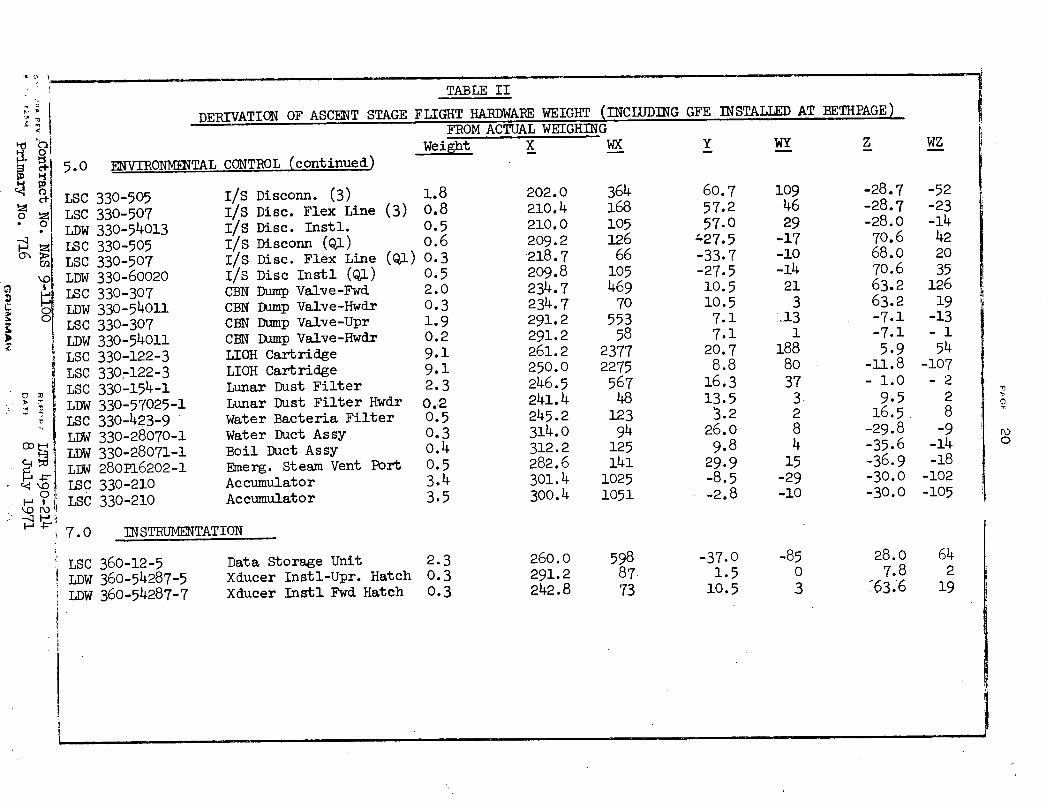
TABLE II
DERIVATION OF ASCENT STAGE FLIGHT HARDWABE WEIGHT (INCLUDING GFE INSTALLED AT BETHPAGE)
WeiFROM ACTUAL WEIGHINGLght X WX
5.0 ENVIRONMENTAL CONTROL (continued)
330-505330-507330-54013330-505330-507330-60020330-307330-54011330-307330-54011330-122-3330-122-3330-154-1330-57025-1330-423-9330-28070-1330-28071-1280P16202-1330-210330-210
I/S Disconn. (3) 1.8I/S Disc. Flex Line (3) 0.8I/S Disc. Instl. 0.5I/S Disconn (Q1) 0.6I/S Disc. Flex Line (Q1) 0.3I/S Disc Instl (Q1) 0.5CBN Dump Valve-Fwd 2.0CBN Dump Valve-Hwdr 0.3CBN Dump Valve-Upr 1.9CBN Dump Valve-Hwdr 0.2LIOH Cartridge 9.1LIOH Cartridge 9.1Lunar Dust Filter 2.3Lunar Dust Filter Hwdr 0.-2Water Bacteria Filter 0.5Water Duct Assy 0.3Boil Duct Assy 0.4Emerg. Steam Vent Port 0.5Accumulator 3.4Accumulator 3.5
202.0210.4210.0209.2218.7209.8234.7234.7291.2291.2261.2250.0246.5241.4245.2314.0312.2282.6301.4300.4
364168105126
6610546970
55358
23772275
56748
1239412514110251051
Y
60.757.257.0
-27.5-33.7-27.510.510.57.17.1
20.78.8
16.313.5
3.226.09.8
29.9-8.5-2.8
WY
1094629
-17-10-14
213
i131
1888037
3284
15-29-10
z
-28.7-28.7-28.070.668.070.663.263.2-7.1-7.15.9
-11.8- 1.0
9.516.5
-29.8-35.6-36.9-30.0-30.0
IN STRUMENTATION
LSC 360-12-5LDW 360-54287-5LDW 360-54287-7
Data Storage UnitXducer Instl-Upr. HatchXducer Instl Fwd Hatch
hi @
_ 'D I
1
1it 4
LSCLSCLDWLSCLSCLDWLSCLDWLSCLDWLSCLSCLSCLDWLSCLDWLDWLDWISCLSC
7.0
WZ
-52-23-14422035
12619
-13-154
-107-2
28
-9-14-18
-102-105
2.30.30.3
0
0
260.0291.2242.8
59887-73
-37.01.5
10.5
-8503
28.07.8
'63.6
642
19
_ ___ _· __
fi
I
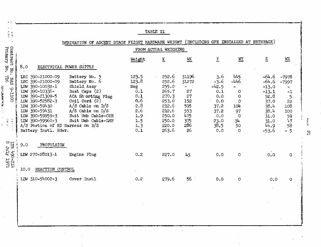
TABLE II
nERITVATTON OF ASCENT STAGE FLIGHT HARDWARE WEIGHT (INCLUDING GFE INSTALLED AT BETHPAGE)· V 'LI WX_ A l ' FROM ACTUAL WEIGHING __ _ _ _ _ _FROM ACTUAL WEIGHING
X
ELECTRICAL POWER SUPPLY
390-21000-09 Battery No. 5390-21000-09 Battery No. 6390-10032-1 Shield Assy390-10336- Dust Caps (2)390-21309-5 ACA Sh-:rting Plug390-52582-3 Coil Cord (2)390-59430 A/S Cable on D/S390-59431 A/S Cable on D/S390-59959-3 Suit Umb Cable-CDR390-59960-3 Suit Umb Cable-LMPPortion of ED Harness on D/S
123.5123.8Neg
0.10.10.62.82.61.91.51.30.1
252.6252.6255.0265.7270.3253.0212.6212.6250.0250.0220.0263.6Battery Instl. Hdwr.
iF
00 I E9.0-!X -I iO; o LDW0
i,
H4 li!1O.(
WX
3119631272
2727
15259555347537528626
PROPULSION
270-28013-1 Engine Plug 0.2 227.0 45
0 REACTION CONTROL
LDW 310-54002-3
0
.
cN-C1
H
cI
H0
.
0> \Ca
TD}_jHOO
8.0
LSCLSCLDWLDWLDWLDW
I' LDWI' T ~Tj LDWLDWLDWA/S
Y
3.6-3.6
-42.50.10.00.037.237.20.023.038.50.0
WY
445-446
0
0o
10497o
34500
z
-64.6-64.6-13.0-13.152.837.038.438.431.031.044.9
-53.6
WZ
-7978-7997
-1522
10810059'4758
-5
0.0
I -. i,
Mu
i N
0 0.0 0 I
! - -
1�
279.6 56Cover Instl 0.2 0.0 O. 0.0 0O

DERIVATION OF ASCENT STAGE
TABLE II
FLIGHT HARDWARE WEIGHT (INCLUDING GFE INSTALLED ATFROM ACTUAL WEIGHING
XWeight WX y
11.O COMMUNICATIONS
Complete
; 12.0 CONTROLS AND DISPLAYS
Complete
13.0 EXPLOSIVES DEVICES
LSCLSCLSCLSCLSCLSCLSCLSCLSCLSCLSCLSCLSCLDWLDWLDWLDWJSFJSF
270-714-113320-301-3320-318-1320-319-1320-319-1320-30400-23320-30400-23320-30400-23320-30400-23320-30400-27320-30400-27320-30400-27320-30400-27320-23412-3320-23412-4320-23413-1-1320 23413-3-1
ElectricIntersta
Prop. He CartridgeRCS Cartridge (4)RCS Cartridge (4)RCS Cartridge AssyRCS Cartridge AssyIntrstg. Nut Cart.Intrstg. Nut Cart.Intrstg. Nut Cart.Intrstg. Nut Cart.Nut AssyNut AssyNut Assy
(10)
(2)(2)
Nut AssyCover Assy -Fwd. Int.Cover Assy - Fwd. Int.Cover Assy. Aft. Int.Cover Assy - Aft.
cal Circuit InstIge Bracket
o
o0
BETHPAGE)
z WZ
1.03.60.40.20.20.10.10.10.10.40.40.40.40.30.30.30.30.11.3
260.1255.0285.0220.5220.5203.7203.7209.2209.2203.7203.7209.2209.2211.7211.7211.7211.7220.5211.7
+260+918+114+ 44+ 44+ 20+ 20+ 21+ 21+ 81+ 81+ 84+ 84+ 64+ 64+ 64+ 6422
275
roro
ro
0.0-42.50.0
+39.6+39.6-65.0+65.0-23.4+23.4-65.0+65.0-23.4+23.4+3.1+3.1+3.1+3.139.63.1
0-153
0+8+8-6.6-2+2
-26+26-9+9+1+1+1+144
-30.2-13.00.0
+48.7+42.4-27.0-27.0+65.9*65.9-27.0-27.0*65.9+65.9+ 4.2+ 4.2+ 4.2+ 4.245.54.2
-30-47
o-10+8-3-3+6+6-11-11+26+26+1+1 .+1+145
_� �_ _I__� _ _ _ � s � I ___·
- I -- I~~~~~~~~~~~~~~~~
7
"7,,
r~
IIti
f
i
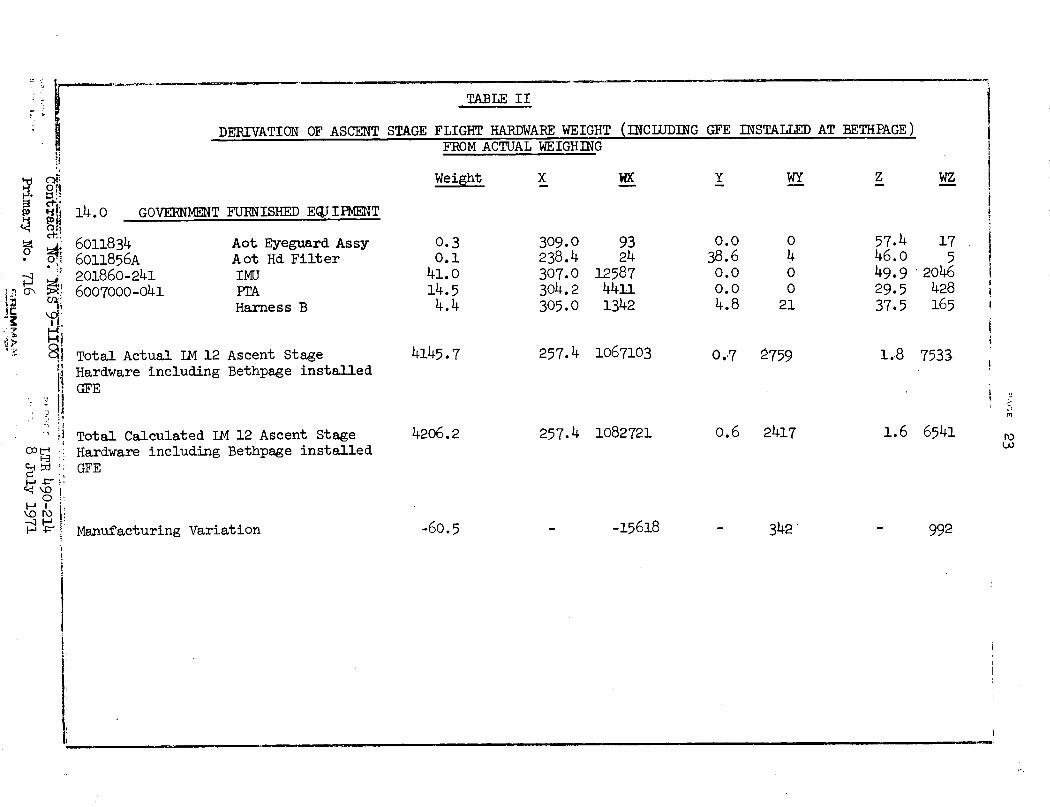
TABLE II
DERIVATION OF ASCENT STAGE FLIGHT HARDWARE WEIGHT (INCLUDING GFE INSTALLED AT BETHPAGE)FROM ACTUAL WEIGHING
Weight X WX y WY z WZ
GOVERNMENT FURNISHED EQJIPMENT
60118346011856A201860-2416007000-041
Total Actual LM 12Hardware includingGFE
Aot Eyeguard AssyAot Hd FilterIMUPTAHarness B
Ascent StageBethpage installed
Total Calculated LM 12 Ascent StageHardware including Bethpage installedGFE
0.30.141.014.54.4
4145.7
4206.2
309.0238.4307.0304.2305.0
9324
1258744111342
257.4 1067103
257.4 1082721
0.038.60.00.04.8
040021
57.446.049.929.537.5
0.7 p759
0.6 2417
175
2046428165
1.8 7533
1.6 6541
-60.5 -15618
14.0
r
U1
I".
q!
i!
: Q>.i
" ii
oo ;i*o,
- 3 j
i
-
.-- ..- __sI-
Manufacturing Variation 342' 992
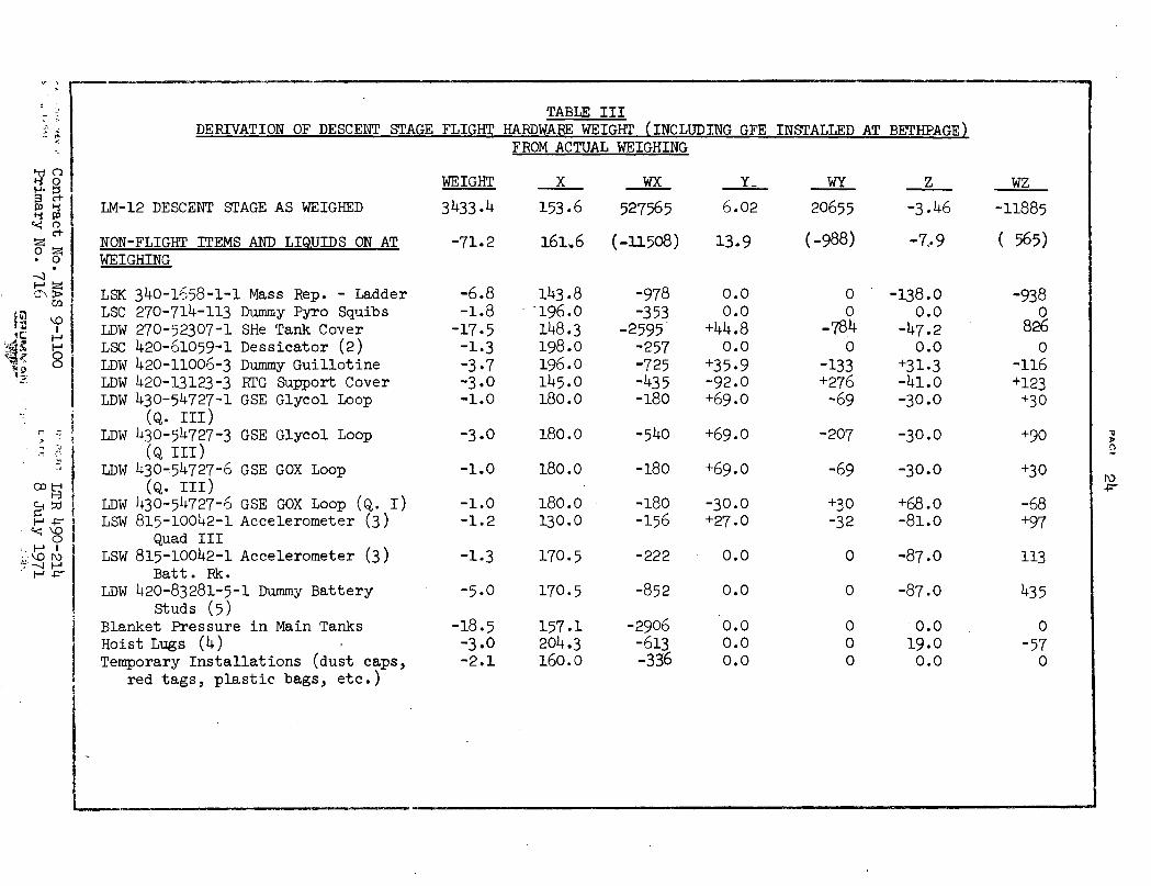
DERIVATION OF DESCENT STAGE FLIGHTTABLE III
HARDWARE WEIGHT (INCLUDING GFE INSTALLED AT RBETHPAGE)FROM ACTUAL WEIGHING
LM-12 DESCENT STAGE AS WEIGHED
NON-FLIGHT ITEMS AND LIQUIDS ON ATWEIGHING
LSK 340-1658-1-1 Mass Rep. - LadderLSC 270-714-113 Dummy Pyro SquibsLDW 270-52307-1 SHe Tank CoverLSC 420-61059-1 Dessicator (2)LDW 420-11006-3 Dummy GuillotineLDW 420-13123-3 RTG Support CoverLDW 430-54727-1 GSE Glycol Loop
(Q. III)LDW 430-54727-3 GSE Glycol Loop
(Q III)LDW 430-54727-6 GSE GOX Loop
(Q. III)LDW 430-54727-o GSE GOX Loop (Q. I)LSW 815-10042-1 Accelerometer (3)
Quad IIILSW 815-10042-1 Accelerometer (3)
Batt. Rk.LDW 420-83281-5-1 Dummy Battery
Studs (5)Blanket Pressure in Main TanksHoist Lugs (4)Temporary Installations (dust caps,
red tags, plastic bags, etc.)
WEIGHT
3433.4
-71.2
-6.8-1.8-17.5-1.3-3.7-3.0-1.0
-3.0
-1.0
-1.0-1.2
-1.3
-5.0
-18.5-3.0-2.1
x WX
153.6 527565
161.6 (-11508)
143.8-196.0148.3198.0196.0145.0180.0
180.0
180.0
180.0130.0
170.5
170.5
157.1204.3160.0
-978-353
-2595-257-725-435-180
6.02
13.9
0.00.0
+44.80.0
+35.9-92.0+69.0
-540 +69.0
-180 +69.0
-180 -30.0-156 +27.0
-222
-852
-2906-613-336
0.0
0.0
0.00.00.0
WY
20655
Z WZ
-3.46
(-988)
00
-7840
-133+276-69
-207
-69
+30-32
-138.00.0
-47.20.0
+31.3-41.0
-30.0
-30.0
-30.0
+68.0-81.0
0 -87.0
0 -87.0
0 0.00 19.00 0.0
1.
ct-
o
T
-11885
( 565)
-938o
8260
-116+123
+30
+90
+30
-68+97
113
435
0
-570
------- I� -�' -- -- -- -- I I- -1
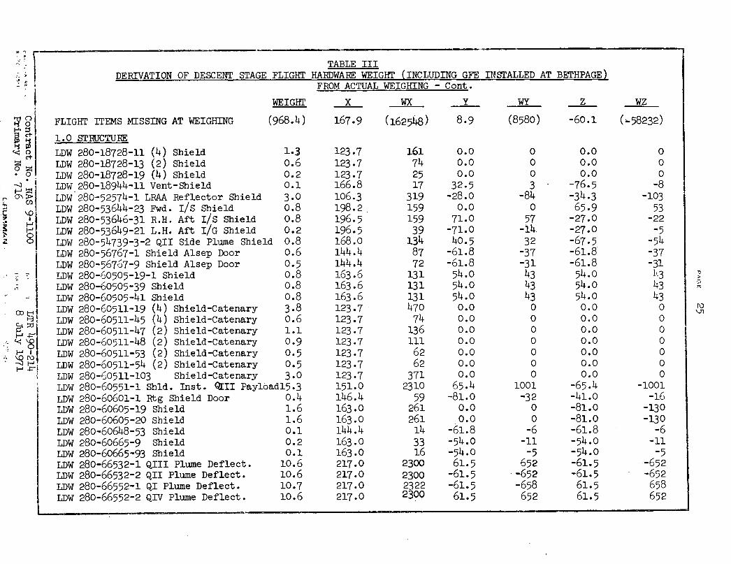
TABLE III
FROM ACTUAL WEIGHING - Cont.
WEIGHT X WX Y WY Z WZ
o, FLIGHT ITEMS MISSING AT WEIGHING (968.4) 167.9 (162548) 8.9 (8580) -60.1 (-58232)
1.0 STRUCTURE
m p LDW 280-18728-11 (4) Shield 1.3 123.7 161 0.0 0 0.0 0ot C LDW 280-18728-13 (2) Shield 0.6 123.7 74 0.0 0 0.0 0. LDW 280-18728-19 (4) Shield 0.2 123.7 25 0.0 0 0.0 0
LDW 280-18944-11 Vent-Shield 0.1 166.8 17 32.5 3 -76.5 -8" g LDW 280-52574-1 LRAA Reflector Shield 3.0 106.3 319 -28.0 -84 -34.3 -103
LDW 280-53644-23 Fwd. I/S Shield 0.8 198.2 159 0.0 0 65.9 53, H LDW 280-53646-31 R.H. Aft I/S Shield 0.8 196.5 159 71.0 57 -27.0 -22> Fo LDW 280-53649-21 L.H. Aft I/G Shield 0.2 196.5 39 -71.0 -14 -27.0 -5
z o LDW 280-54739-3-2 QII Side Plume Shield 0.8 168.0 134 40.5 32 -67.5 -54LDW 280-56767-1 Shield Alsep Door 0.6 144.4 87 -61.8 -37 -61.8 -37LDW 280-56767-9 Shield Alsep Door 0.5 144.4 72 -61.8 -31 -61.8 -31LDW 280-60505-19-1 Shield 0.8 163.6 131 54.0 43 54.0 43 LDW 280-60505-39 Shield 0.8 163.6 131 54.0 43 54.0 43LDW 280-60505-41 Shield 0.8 163.6 131 54.0 43 54.0 43LDW 280-60511-19 (4) Shield-Catenary 3.8 123.7 470 0.0 0 0.0 0 uLDW 280-60511-45 (4) Shield-Catenary 0.6 123.7 74 0.0 0 0.0 0LDW 280-60511-47 (2) Shield-Catenary 1.1 123.7 136 0.0 0 0.0 0LDW 280-60511-48 (2) Shield-Catenary 0.9 123.7 111 0.0 0 0.0 0
\_ Z LDW 280-60511-53 (2) Shield-Catenary 0.5 123.7 62 0.0 0 0.0 0LDW 280-60511-54 (2) Shield-Catenary 0.5 123.7 62 0.0 0 0.0 0LDW 280-60511-103 Shield-Catenary 3.0 123.7 371 0.0 0 0.0 0LDW 280-60551-1 Shld. Inst. GII Payloadl5.3 151.0 2310 65.4 1001 -65.4 -1001LDW 280-60601-1 Rtg Shield Door 0.4 146.4 59 -81.0 -32 -41.0 -16LDW 280-60605-19 Shield 1.6 163.0 261 0.0 0 -81.0 -130LDW 280-60605-20 Shield 1.6 163.0 261 0.0 0 -81.0 -130LDW 280-60648-53 Shield 0.1 144.4 14 -61.8 -6 -61.8 -6LDW 280-60665-9 Shield 0.2 163.0 33 -54.0 -11 -54.0 -11LDW 280-60665-93 Shield 0.1 163.0 16 -54.0 -5 -54.0 -5LDW 280-66532-1 QIII Plume Deflect. 10.6 217.0 2300 61.5 652 -61.5 -652LDW 280-66532-2 QII Plume Deflect. 10.6 217.0 2300 -61.5 -652 -61.5 -652LDW 280-66552-1 QI Plume Deflect. 10.7 217.0 2322 -61.5 -658 61.5 658LDW 280-66552-2 QIV Plume Deflect. 10.6 217.0 2300 61.5 652 61.5 652
j
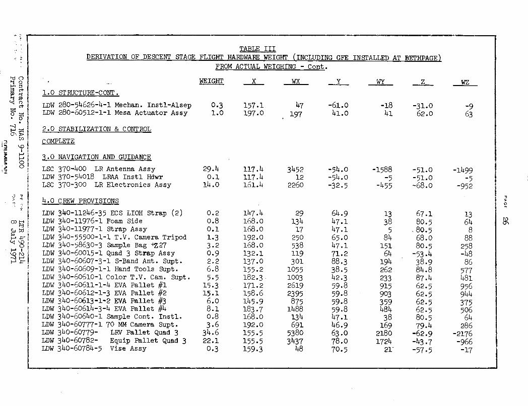
TABLE IIIDERIVATION OF DESCENT STAGE FLIGHT HARDWARE WEIGHT (INCLUDING GFE INSTALLED AT BETHPAGE)
FROM ACTUAL WEIGHING - Cont.
_. .WEIGHT X WX Y WY Z WZ
1.0 STRUCTURE-CONT.
LDW 280-54626-4-1 Mechan. Instl-Alsep 0.3 157.1 47 -61.0 -18 -31.0 -9LDW 280-60512-1-1 Mesa Actuator Assy 1.0 197.0 197 41.0 41 62.0 63
2.0 STABILIZATION & CONTROL
COMPLETE
3.0 NAVIGATION AND GUIDANCE
LSC 370-400 LR Antenna Assy 29.4 117.4 3452 -54.0 -1588 -51.0 -1499LDW 370-54018 LRAA Instl Hdwr 0.1 117.4 12 -54.0 -5 -51.0 -5LSC 370-300 LR Electronics Assy 14.0 161.4 2250 -32.5 -455 -68.0 -952
4.0 CREW PROVISIONS
LDW 340-11246-35 ECS LIOH Strap (2) 0.2 147.4 29 64.9 13 67.1 13LDW 340-11976-1 Foam Side 0.8 168.0 134 47.1 38 80.5 64LDW 340-11977-1 Strap Assy 0.1 168.0 17 47.1 5 ;80.5 8LDW 340-55500-1-1 T.V. Camera Tripod 1.3 192.0 250 65.0 84 68.0 88LDW 340-58630-3 Sample Bag +Z27 3.2 168.0 538 47.1 151 80.5 258LDW 340-60015-1 Quad 3 Strap Assy 0.9 132.1 119 71.2 64 -53.4 -48LDW 340-60607-3-1 S-Band Ant. Supt. 2.2 137.0 301 88.3 194 38.9 86LDW 340-60609-1-1 Hand Tools Supt. 6.8 155.2 1055 38.5 262 84.8 577LDW 340-60610-1 Color T.V. Cam. Supt. 5.5 182.3 1003 42.3 233 87.4 481LDW 340-60611-1-4 EVA Pallet #1 15.3 171.2 2619 59.8 915 62.5 955LDW 340-60612-1-3 EVA Pallet #2 15.1 158.6 2395 59.8 903 62.5 944LDW 340-60613-1-2 EVA Pallet #3 6.0 145.9 875 59.8 359 62.5 375LDW 340-60614-3-4 EVA Pallet #4 8.1 183.7 1488 59.8 484 62.5 506LDW 340-60640-1 Sample Cont. Instl. 0.8 168.0 134 47.1 38 80.5 64LDW 340-60777-1 70 MM Camera Supt. 3.6 192.0 691 46.9 169 79.4 286LDW 340-60779- LRV Pallet Quad 3 34.6 155.5 5380 63.0 2180 -62.9 -2176LDW 340-60782- Equip Pallet Quad 3 22.1 155.5 3437 78.0 1724 -43.7 -966LDW 340-60784-5 Vise Assy 0.3 159.3 48 70.5 21- -57.5 -17
-tinR CO
;I P0
o
· 0
H
O0
i
DERIVATION OF DESCENT STAGE FLIGHT
TABLE III
HARDWARE WEIGHT (INCLUDING GFE INSTALLED AT BETHPAGE)
FROM ACTUAL WEIGHING - Cont.
WEIGHT
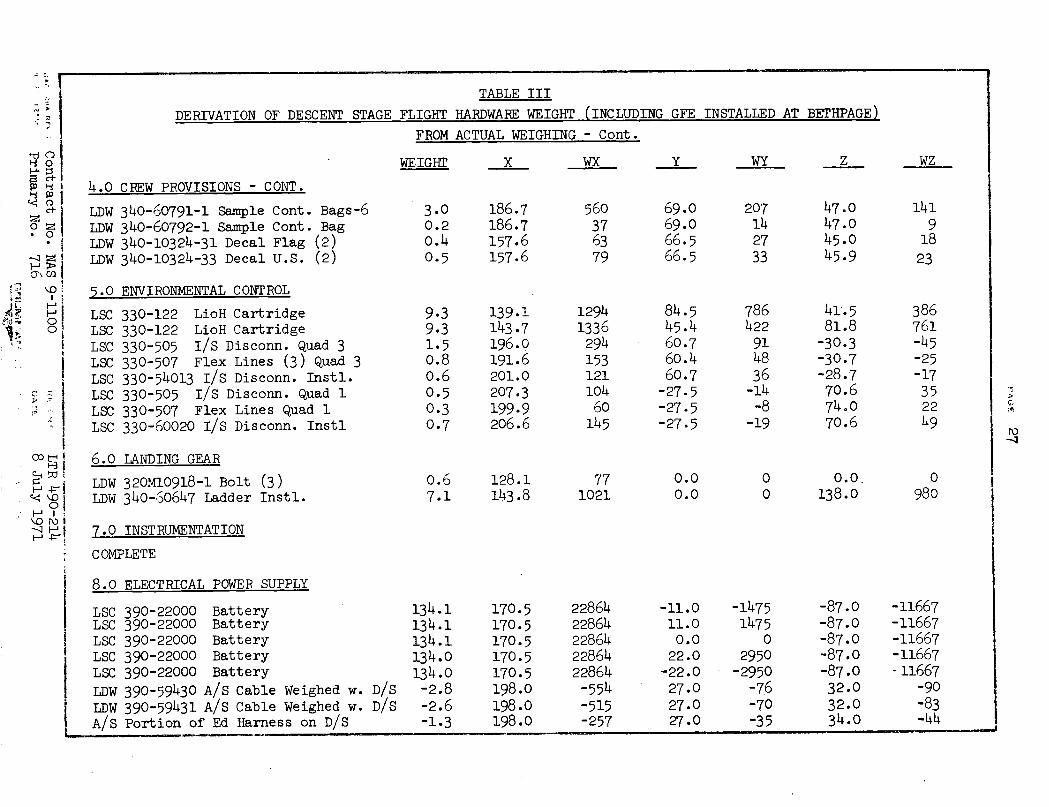
4.0 CREW PROVISIONS - CONT.
LDW 340-60791-1 Sample Cont. Bags-6LDW 340-60792-1 Sample Cont. BagLDW 340-10324-31 Decal Flag (2)LDW 340-10324-33 Decal U.S. (2)
5.0 ENVIRONMENTAL CONTROL
LSCLSCLSCLSCLSCLSCLSCLSC
330-122 LioH Cartridge330-122 LioH Cartridge330-505 I/S Disconn. Quad 3330-507 Flex Lines (3) Quad 3330-54013 I/S Disconn. Instl.330-505 I/S Disconn. Quad 1330-507 Flex Lines Quad 1330-60020 I/S Disconn. Instl
3.00.20.4
0.5
9.39.31.50.80.6
0.50.30.7
X
186.7186.7157.6157.6
139.1143.7196.0191.6201.0207.3199.9206.6
WX Y
560376379
12941336294153121104
60145
69.069.066.566.5
84.545.460.760.460.7-27.5-27.5-27.5
WY
207142733
786422914836-14-8
-19
z
47.047.045.045.9
41.581.8-30.3-30.7-28.770.674.070.6
6.0 TANDITNG GRAR
LDW 320M10918-1 Bolt (3)LDW 340-60647 Ladder Instl.
0.67.1
128.1143.8
771021
0.00.0
0 0.0.O 138.0
7.0 TNSTRUIMENTATION
COMPLETE
8.0 ELECTRICAL POWER SUPPLY
LSCLSCLSCLSCLSC
LDWLDWA/S
390-22000 Battery390-22000 Battery390-22000 Battery390-22000 Battery390-22000 Battery
390-59430 A/S Cable Weighed w. D/S390-59431 A/S Cable Weighed w. D/SPortion of Ed Harness on D/S
c., I
ro
. O
O
: 0F1s
-s- OI
OD tE I~-4IO3 1
.- r WH i
0 -
o r i
--- H I
WZ
141
918
23
386761-45-25-17352249
0980
134.1134.1134.1134.0134.0-2.8-2.6-1.3
170.5170.5170.5170.5170.5198.0198.0198.0
2286422864228642286422864-554-515-257
-11.011.00.022.0-22.027.027.027.0
-14751475
02950-2950
-76-70-35
-87.0-87.0-87.0-87.0-87.032.032.034.0
-11667-11667-11667-11667- 11667
-90-83-44
_ � _ _ _ _ _I _ _
w -- - - -I _ -- -I - -- - 5 - '
c.
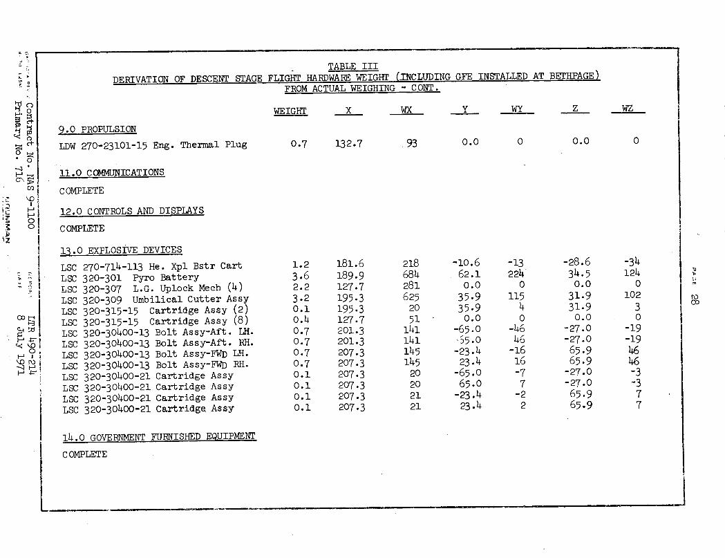
TABLE IIIDERIVATION OF DESCENT STAGE FLIGHT HARDWARE WEIGHT (INCLUDING GFE INSTALLED AT BETHPAGE)
FROM ACTUAL WEIGHING - CONT.
WEIGHT X WX Y WY Z WZ
9.0 PROPULSION
LDW 270-23101-15 Eng. Thermal Plug 0.7 132.7 93 0.0 0 0.0 0
11.0 COMMUNICATIONS
* I' COMPLETE
:': Ji 12.0 CONTROLS AND DISPLAYS
o ! COMPLETE
! 13.0 EXPLOSIVE DEVICES
LSC 270-714-113 He. Xpl Bstr Cart 1.2 181.6 218 -10.6 -13 -28.6 -34> I LSC 320-301 Pyro Battery 3.6 189.9 684 62.1 224 34.5 124
LSC 320-307 L.G. Uplock Mech (4) 2.2 127.7 281 0.0 0 0.0 0LSC 320-309 Umbilical Cutter Assy 3.2 195.3 625 35-9 115 31.9 102LSC 320-315-15 Cartridge Assy (2) 0.1 195.3 20 35.9 4 31.9 3 coLSC 320-315-15 Cartridge Assy (8) 0.4 127.7 51 0.0 0 0.0 0LSC 320-30400-13 Bolt Assy-Aft. LH. 0.7 201.3 141 -65.0 -46 -27.0 -19LSC 320-30400-13 Bolt Assy-Aft. RH. 0.7 201.3 141 ,5.0 46 -27.0 -19-LSC 320-30400-13 Bolt Assy-FWD LH. 0.7 207.3 145 -23.4 -16 65.9 46
°- -- LSC 320-30400-13 Bolt Assy-FWD RH. 0.7 207.3 145 23.4 16 65.9 46LSC 320-30400-21 Cartridge Assy 0.1 207.3 20 -65.0 -7 -27.0 -3LSC 320-30400-21 Cartridge Assy 0.1 207.3 20 65.0 7 -27.0 -3i LSC 320-30400-21 Cartridge Assy 0.1 207.3 21 -23.4 -2 65.9 7LSC 320-30400-21 Cartridge Assy 0.1 207.3 21 23.4 2 65.9 7
14.0 GOVERNMENT FURNISHED EQUIPMENT
COMPLETE
_----- _.--- _~--- - -
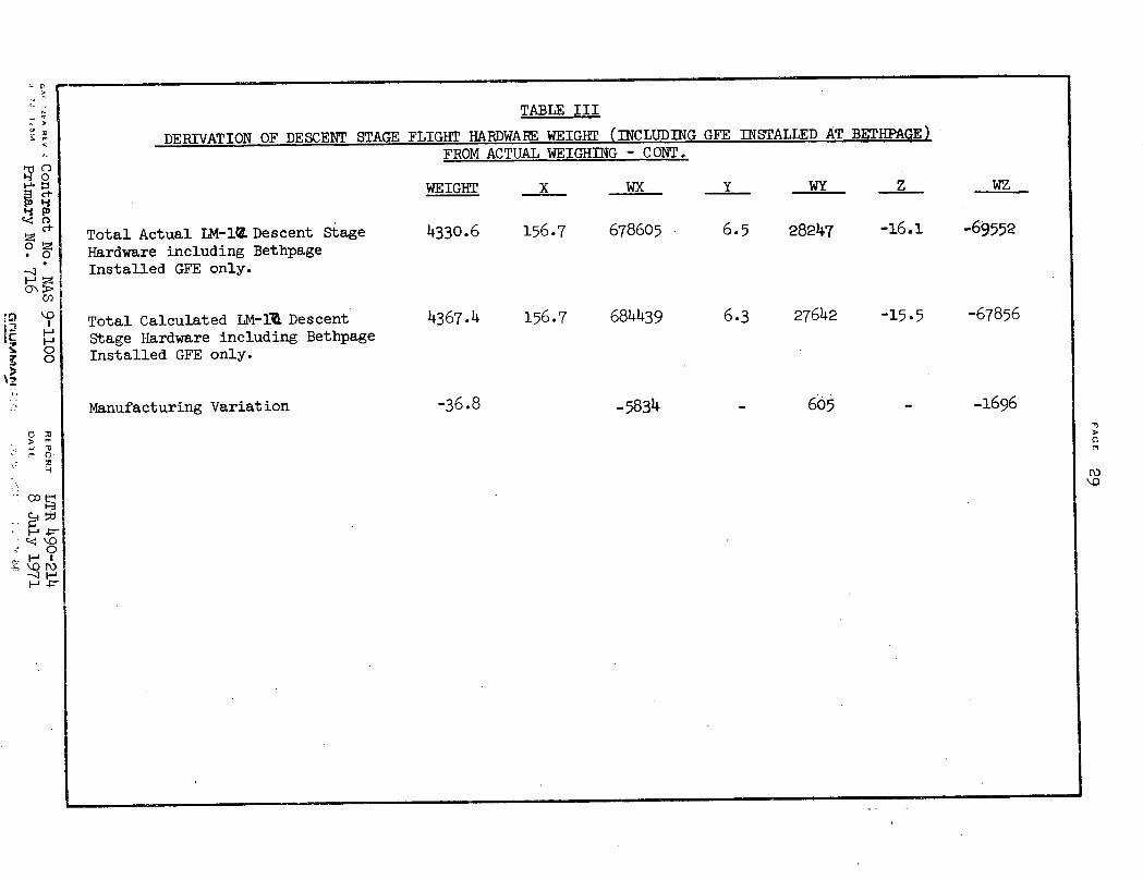
TABLE III
DERIVATION OF DESCENT STAGE FLIGHT HARDWARE WEIGHT (INCLUDING GFE INSTALLED AT BETHPAGE)FROM ACTUAL WEIGHING - CONT.
WEIGHT X WX Y WY Z
Total Actual IM-1i Descent StageHardware including BethpageInstalled GFE only.
Total Calculated LM-1A DescentStage Hardware including BethpageInstalled GFE only.
Manufacturing Variation
4330.6
4367.4
156.7
156.7
-36.8
678605
684439
-5834
6.5 28247
6.3 27642
605
-16.1
-15.5
-69552
-67856
-1696
C.
D~O
I-~~ ~ ~ _- .I J
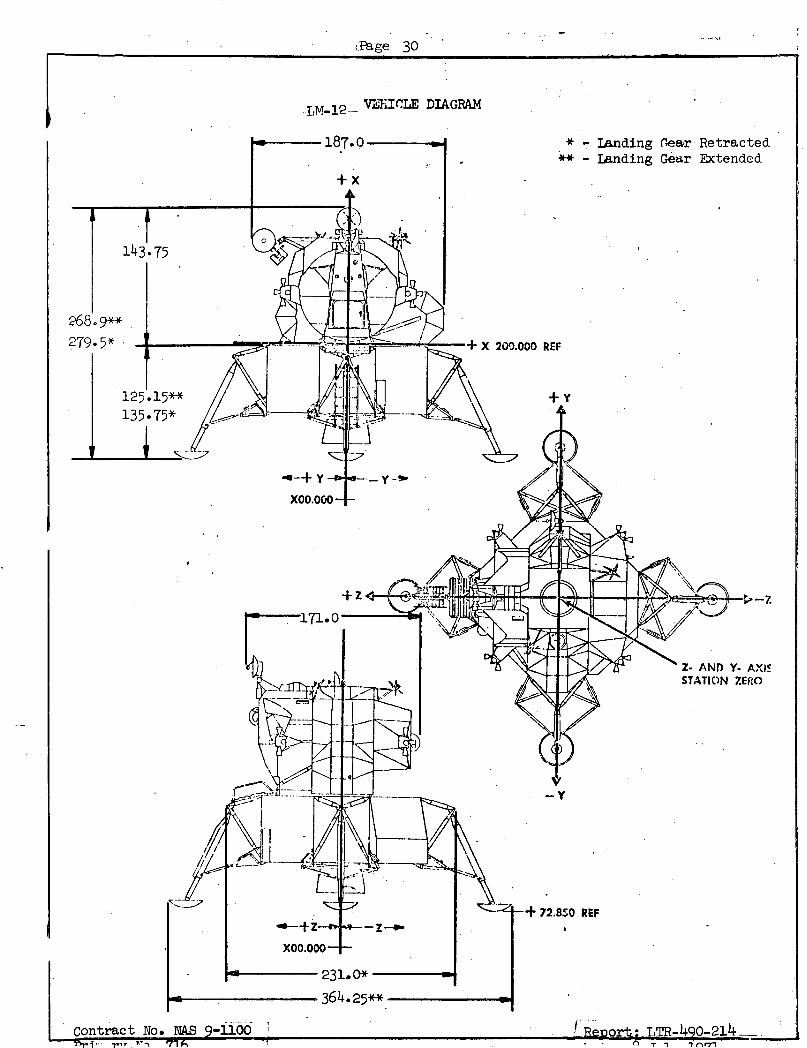
.Page 30
-LM-12-- V'HTIE DIAGRAM
* - Landing (ear Retracted** - Landing Gear Extended
Z- AND Y. AXI c
STATION ZERO
72.850 REF
! Relonrt: TR-49q0-214__.
+
364.25**
-tli"' rat nq 1lhLJon T .. am U ±r* M e EVJ - ____ -o , _ . _ __
lk ll", TA - ---1 nr7nntrant N. NAS Q o-1100hn i
i I I r)' J
PAc4A 31
FIGURE 1
Ascent Stage Center of Gravity/Thrust Vector Offset
vs. Control Boundary
Information to follow under separate cover. This data willnow be supplied in the TIM Mass Properties Data Book (Reference 4)as directed by CCA 2864 (Reference 3).
,, ,.Contract No. NAS 5e i" '"I , Primary No. 716
-I9-110() P,,.,A ,r LTR-490-214
I. A, 8 July 1971F..PAt I PlAMA r . , - .GR W/I LI

PA.:E 32
FIGURE II
Descent Stage Center of Gravity Offset
vs. Control Boundary
Information to follow under separate cover. This data willnow be supplied in the LM Mass Properties Data Book (Reference 4)as directed by CCA 2864 (Reference 3).
.A. -. ,A RCpntract No. NAS 9-8-7J 1,151 Primary No. 716
1100 ~. ., FT LTR 490-214DATE 8 July 1971
',&1.UMMAN- .'P; ='' :'- , :: ' .! .', ': ·',in' I. r
- c IY·l- ----�-·-· - -- -
pA__ 33
Derivation of the Dry LM-12 Mass Properties at EarthLaunch
Information to follow under separate cover. This data willnow be supplied in the T,M Mass Properties Data Book (Reference 4)as directed by CCA 2864 (Reference 3).
- contract loo. NASY-,.A: Pia'rA FNE. 2
B.- I'b, I Primary No. 716LIUO RFPI H r LTR 490-214
[.A i'r 8 July 1971CF:RUM!. MAY! . I ' .. ,'
. ,,^

PAGE 34----- - -- ---
The Mass Properties of the LM-12 Vehicle at Pertinent Pointsin the Mission as Obtained from the T,M-12 Mass Properties
Data Book, LDP 490-12 to be Released
Information to follow under separatewith the direction of CCA 2864 (Reference 3)will no longer be supplied in this document;are shown in the referenced data book.
cover. In accordancethis information will nothe mass properties
Contract No. NAS9-1100 Ft'OFQr LTR 490-214
Primary No. 716 COTE 8 July 1971-UR"JF .W ; . : - . I n
as )D X
;A. 't2I3 REV 2
a .', 125M
I
PAC, F 35
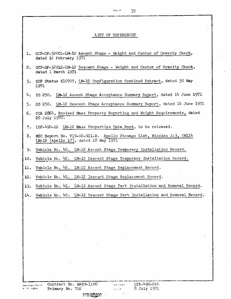
LIST OF REFERENCES
OCP-GF-32001-LM-12 Ascent Stage - Weight and Center of Gravity Check,dated 12 February 1971
OCP-GF-32012-LM-12 Descent Stage - Weight and Center of Gravity Check,dated 1 March 1971
EDP Status K10707, LM-12 Configuration Combined Extract, dated 30 May
1971
DD 250. LM-12 Ascent Stage Acceptance Summary Report, dated 14 June 1971
DD 250. LM-12 Descent Stage Acceptance Summary Report, dated 14 June 1971
CCA 2864, Revised Mass Property Reporting and Weight Requirements, dated20 July 1970.
LDP-490-12 LM-12 Mass Properties Data Book, to be released.
MSC Report No. V19-02-911-B. Apollo Stowage List, Mission J-3, CM114LM-12 (Apollo 17), dated 18 May 1971
Vehicle No. 42. LM-12 Ascent Stage Temporary Installation Record.
Vehicle No. 42. LM-12 Descent Stage Temporary Installation Record.
Vehicle No. 42. LM-12 Ascent Stage Replacement Record.
Vehicle No. 42. LM-12 Descent Stage Replacement Record.
Vehicle No. 42.
Vehicle No. 42.
LM-12 Ascent Stage Part Installation and Removal Record.
LM-12 Descent Stage Part Installation and Removal Record.
oAC 32.. R.V 2 Contract No. NAS9-11009o 70z 125 Primary No. 716
,M;S,-
I r
LTR-490-2148 July 1971
1.
2.
3.
4.
5.
6.
7.
8.
9.
10.
11.
12.
13.
14.
PA.;F . 3b
EXTFRNAL DISTRIBUTION LIST
28 - Copies
2 - Copies
Attention:
1 - Copy
2 - Copies
1 - Copy
1 - Copy PB (RASPO)
c:Ou.1thi$;t NO. NAS 9-11008 ;, Orary No. 716
RE.PO iT LTR-490-214DATrE 8 July 1971
GRUMMAN . ;- . ! :- / '.? : ':'
MSC
HDQ
MAS-4
MAT-2
KSC
MSFC
MIT
,~__ T _ 74. _ - I - I I _
PAGE 37
= , _ _ _
INTERNAL DISTRIBUTION LIST
Executive and Technical Review Board Design Engineering
Gavin, J. G. - Exec. - Plant 25 (1)Hedrick, I. G. - Exec. - Plant 5 (1)Skurla, G. - Plant 5 (1)Tripp, R. H. - Plant 25 (1)Bonan, E. - Dir. of Syst. Tech. (1)Lewin, N. - Manager of Syst. Engr(l)
Program Staff - LM
Asst. Program Director - Eng'g.Deputy Ass't. Program DirectorEng.Spacecraft Directors OfficeSystems Eng'g ManagerDesign Engineering Manager
CommuncationsCrew ProvisionsElectrical AssembliesElectrical PowerEnvironmental ControlGuidance, Nav. & ControlInstrumentationPropulsionRadarVehicle Design Integration(1)
(1)(1)(1)(1)
Mission Support Engineering
Mission Analysis andSimulation
Structural AnalysisMission Support and
EvaluationThermodynamics
Engineering Staff
Weight Control - Admin. Assistant(3)Plant 35
et. al.
Library Technical Services-PlantLM Data Services
KSC (Attn. J. K, Watson)
Houston'(Attn. G. McNally)
35(1)(1)
(1)
(1)
Contract No. NAS 9-1100Primary No. 716
s_,;O. V '
,'.F.FO,- LTR-490-214,.' - 8 July 1971
(1)(1)(1)(1)(1)(1)(1)(1)(1)(1)
(1)(1)
(1)(1)
hb 1) 2 .'
, , , _ _ _ __
I