Embed Size (px)
Citation preview

Product safety and failure analysis
ESPEC Technology Report No.61
1
T
Technology Report
Product failure mechanisms and reliability testing
Part 1: Motors and transformers
Masahiro Yamaura ESPEC CORP., Reliability Research Headquarters,
Analysis Center, Calibration Group
his report is an expanded version of excerpts taken by Espec from
presentations made at a product reliability seminar given by the Reliability
Subcommittee of the Kansai Electronic Industry Development Center (KEC),
and from material published in the journal KEC Jōhō (issue No. 214 of July, 2010).
Motors and transformers comprised mainly of magnet wires are in widespread use, and
are generally highly reliable components. But occasional news stories about fires caused
by electric fans suggest that motor or transformer problems can sometimes lead directly
to serious product failures, and survey indicate that such cases are more common that
might be expected.
This report presents the findings of a survey on the mechanisms responsible for product
failures. It is based on actual cases in which products with motors or transformers
caused serious product failures reported by the National Institute of Technology and
Evaluation (NITE). These findings are followed by a description of a reliability test
method that uses a better understanding of product failure mechanisms to reveal
potential market failures.
2.1 Breakdown by product
This section presents the breakdown of the surveyed product failures by category (for
each material responsible). These failures occurred between 2001 and 2007, and their
causes were classified by NITE as ‘C1’ (failures thought to have been caused by an old
product or a product with degraded performance from extended use).
2.1.1. Product failures caused by motors
Figures 1 and 2 show the breakdown of the 17 motor-linked product failures surveyed.
Electric fans were the most failure-prone product type in this category, accounting for
Introduction 1
Failure of products used for extended periods of time 2
Product safety and failure analysis
ESPEC Technology Report No.61
2
about half of these cases. Product failures caused by fan motors were most often due to
deterioration of the insulation on the coil’s magnet wire. The motor-linked product
failures surveyed occurred after 10 to 40 years of product use, with occurrence spread
evenly over this period of time.
Fig. 1 Failure ratio by category (motors)
Fig.2 Number of product failures by years of product use (motors)
2.1.2. Product failures caused by transformers
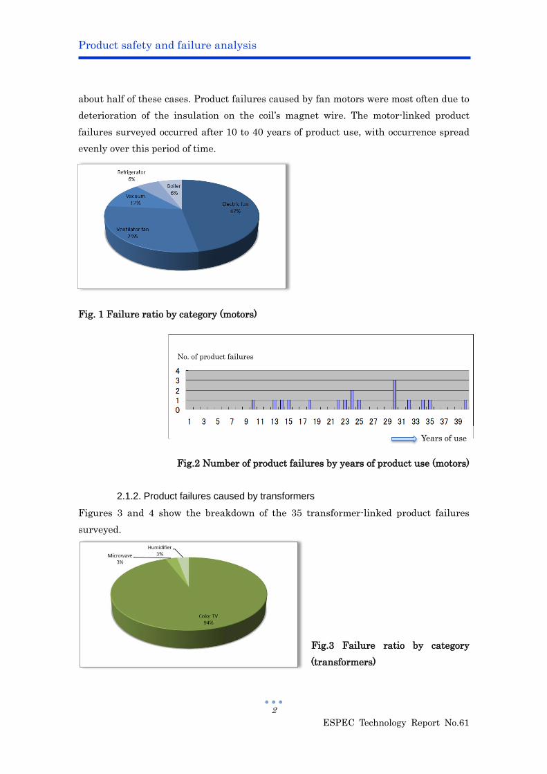
Figures 3 and 4 show the breakdown of the 35 transformer-linked product failures
surveyed.
Fig.3 Failure ratio by category
(transformers)
No. of product failures
Years of use
Product safety and failure analysis
ESPEC Technology Report No.61
3
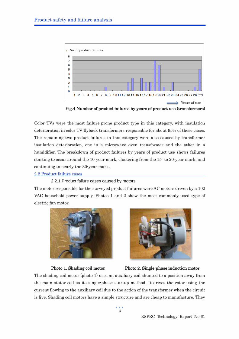
Fig.4 Number of product failures by years of product use (transformers)
Color TVs were the most failure-prone product type in this category, with insulation
deterioration in color TV flyback transformers responsible for about 95% of these cases.
The remaining two product failures in this category were also caused by transformer
insulation deterioration, one in a microwave oven transformer and the other in a
humidifier. The breakdown of product failures by years of product use shows failures
starting to occur around the 10-year mark, clustering from the 15- to 20-year mark, and
continuing to nearly the 30-year mark.
2.2 Product failure cases
2.2.1 Product failure cases caused by motors
The motor responsible for the surveyed product failures were AC motors driven by a 100
VAC household power supply. Photos 1 and 2 show the most commonly used type of
electric fan motor.
Photo 1. Shading coil motor Photo 2. Single-phase induction motor
The shading coil motor (photo 1) uses an auxiliary coil shunted to a position away from
the main stator coil as its single-phase startup method. It drives the rotor using the
current flowing to the auxiliary coil due to the action of the transformer when the circuit
is live. Shading coil motors have a simple structure and are cheap to manufacture. They
Years of use
n/a
No. of product failures
Product safety and failure analysis
ESPEC Technology Report No.61
4
have few components that fail or restrict service life.
The single-phase induction motor (photo 2) uses a capacitor as its startup method and
drives the rotor by staggering the phases of the main coil and auxiliary coil. While this
type of motor is also actually sound, it has been responsible for a greater number of
product failures than the number of electric fan motor failures given in section 2.1, since
product failures also occur for another reason (the capacitor).
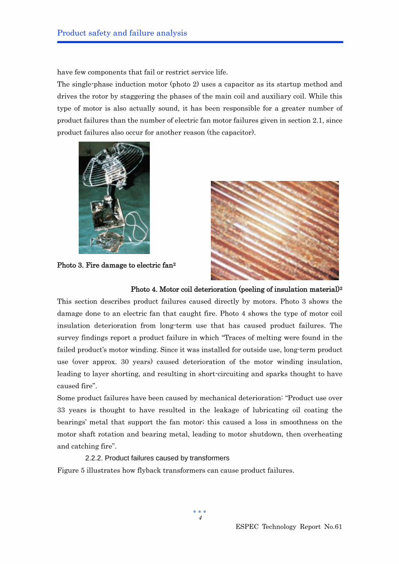
Photo 3. Fire damage to electric fan2
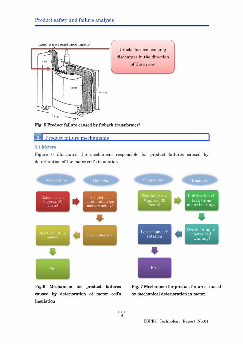
Photo 4. Motor coil deterioration (peeling of insulation material)2
This section describes product failures caused directly by motors. Photo 3 shows the
damage done to an electric fan that caught fire. Photo 4 shows the type of motor coil
insulation deterioration from long-term use that has caused product failures. The
survey findings report a product failure in which “Traces of melting were found in the
failed product’s motor winding. Since it was installed for outside use, long-term product
use (over approx. 30 years) caused deterioration of the motor winding insulation,
leading to layer shorting, and resulting in short-circuiting and sparks thought to have
caused fire”.
Some product failures have been caused by mechanical deterioration: “Product use over
33 years is thought to have resulted in the leakage of lubricating oil coating the
bearings’ metal that support the fan motor; this caused a loss in smoothness on the
motor shaft rotation and bearing metal, leading to motor shutdown, then overheating
and catching fire”.
2.2.2. Product failures caused by transformers
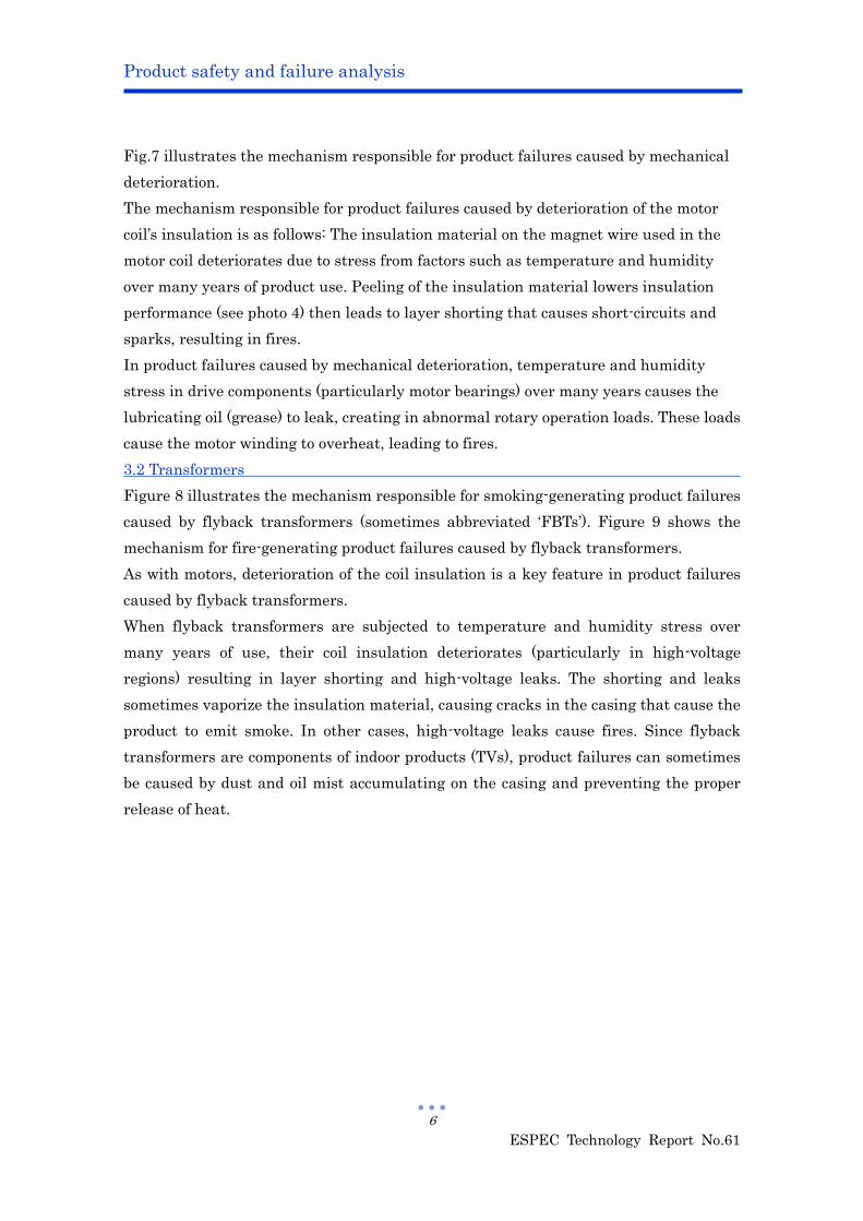
Figure 5 illustrates how flyback transformers can cause product failures.
Product safety and failure analysis
ESPEC Technology Report No.61
5
Extended use (approx. 30
years)
Insulation deterioration (on motor winding)
Layer shorting Short-circuiting,
sparks
Fire
Extended use (approx. 30
years)
Lubrication oil leak (from
motor bearings)
Overheating (in motor coil winding)
Loss of smooth rotation
Fire
Fig. 5 Product failure caused by flyback transformer2
3.1 Motors
Figure 6 illustrates the mechanism responsible for product failures caused by
deterioration of the motor coil’s insulation.
Product failure mechanisms 3
6.1 cm
6 ml
core
Lead wire resistance inside
Cracks formed, causing
discharges in the direction
of the arrow
Temperature Humidity Humidity Temperature
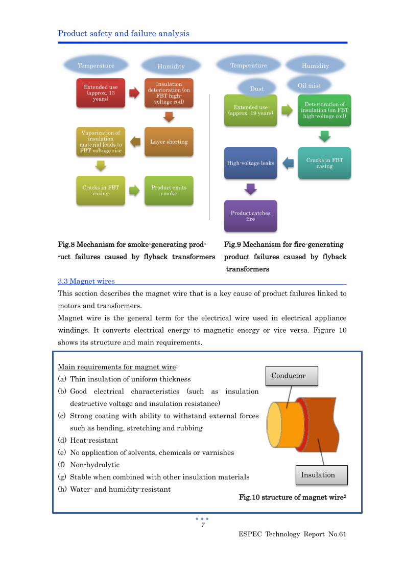
Fig.6 Mechanism for product failures
caused by deterioration of motor coil’s
insulation
Fig. 7 Mechanism for product failures caused
by mechanical deterioration in motor
Product safety and failure analysis
ESPEC Technology Report No.61
6
Fig.7 illustrates the mechanism responsible for product failures caused by mechanical
deterioration.
The mechanism responsible for product failures caused by deterioration of the motor
coil’s insulation is as follows: The insulation material on the magnet wire used in the
motor coil deteriorates due to stress from factors such as temperature and humidity
over many years of product use. Peeling of the insulation material lowers insulation
performance (see photo 4) then leads to layer shorting that causes short-circuits and
sparks, resulting in fires.
In product failures caused by mechanical deterioration, temperature and humidity
stress in drive components (particularly motor bearings) over many years causes the
lubricating oil (grease) to leak, creating in abnormal rotary operation loads. These loads
cause the motor winding to overheat, leading to fires.
3.2 Transformers
Figure 8 illustrates the mechanism responsible for smoking-generating product failures
caused by flyback transformers (sometimes abbreviated ‘FBTs’). Figure 9 shows the
mechanism for fire-generating product failures caused by flyback transformers.
As with motors, deterioration of the coil insulation is a key feature in product failures
caused by flyback transformers.
When flyback transformers are subjected to temperature and humidity stress over
many years of use, their coil insulation deteriorates (particularly in high-voltage
regions) resulting in layer shorting and high-voltage leaks. The shorting and leaks
sometimes vaporize the insulation material, causing cracks in the casing that cause the
product to emit smoke. In other cases, high-voltage leaks cause fires. Since flyback
transformers are components of indoor products (TVs), product failures can sometimes
be caused by dust and oil mist accumulating on the casing and preventing the proper
release of heat.
Product safety and failure analysis
ESPEC Technology Report No.61
7
Extended use (approx. 13
years)
Insulation deterioration (on
FBT high-voltage coil)
Layer shorting
Vaporization of insulation
material leads to FBT voltage rise
Cracks in FBT casing
Product emits smoke
Extended use (approx. 19 years)
Deterioration of insulation (on FBT high-voltage coil)
Cracks in FBT casing
High-voltage leaks
Product catches fire
Fig.8 Mechanism for smoke-generating prod- Fig.9 Mechanism for fire-generating
-uct failures caused by flyback transformers product failures caused by flyback
transformers
3.3 Magnet wires
This section describes the magnet wire that is a key cause of product failures linked to
motors and transformers.
Magnet wire is the general term for the electrical wire used in electrical appliance
windings. It converts electrical energy to magnetic energy or vice versa. Figure 10
shows its structure and main requirements.
Main requirements for magnet wire:
(a) Thin insulation of uniform thickness
(b) Good electrical characteristics (such as insulation
destructive voltage and insulation resistance)
(c) Strong coating with ability to withstand external forces
such as bending, stretching and rubbing
(d) Heat-resistant
(e) No application of solvents, chemicals or varnishes
(f) Non-hydrolytic
(g) Stable when combined with other insulation materials
(h) Water- and humidity-resistant
Temperature Humidity Temperature Humidity
Oil mist Dust
Conductor
Insulation
Fig.10 structure of magnet wire2

Product safety and failure analysis
ESPEC Technology Report No.61
8
Magnet wire uses extremely thin insulation material to maintain insulation
performance and protect the wire from various environmental factors, and has a major
effect on component service life. Since the life of insulation the material used
determines the life of the magnet wire, plastic are usually used.
Fig.11 Magnet wire service life curves1
Magnet wire is classified according to the heat resistance characteristic of its insulation
material (into classes Y, A, E, B, F, H and C). In conformance with the Arrhenius law,
the service life of each insulation class is normally 40,000 hours (or 20,000 hours under
the UL standard) at the maximum tolerance temperature for the class. The class of
motor insulation used is determined by the temperature rise caused by the heat of the
motor and by the operating environment. In addition to the insulation service life
characteristic, insulation performance is greatly affected by any contamination, by
impurities or damage to the insulation during manufacture. Similar insulation
Service
life (hr)
Polyester
Polyesterimide
Polyamide
Polyamideimide
Formal
Polyurethane
Product safety and failure analysis
ESPEC Technology Report No.61
9
problems can also be caused when the insulation is applied to the coil.
The aging of these problems caused during manufacture can cause problems that were
not initially apparent to exacerbate product failure factors.
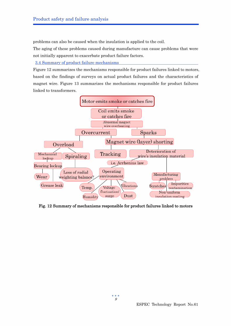
3.4 Summary of product failure mechanisms
Figure 12 summarizes the mechanisms responsible for product failures linked to motors,
based on the findings of surveys on actual product failures and the characteristics of
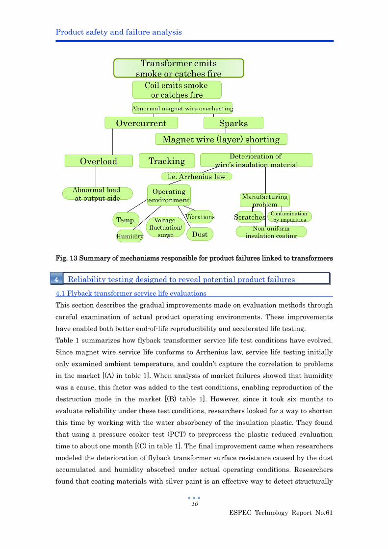
magnet wire. Figure 13 summarizes the mechanisms responsible for product failures
linked to transformers.
Fig. 12 Summary of mechanisms responsible for product failures linked to motors
Product safety and failure analysis
ESPEC Technology Report No.61
10
Fig. 13 Summary of mechanisms responsible for product failures linked to transformers
4.1 Flyback transformer service life evaluations
This section describes the gradual improvements made on evaluation methods through
careful examination of actual product operating environments. These improvements
have enabled both better end-of-life reproducibility and accelerated life testing.
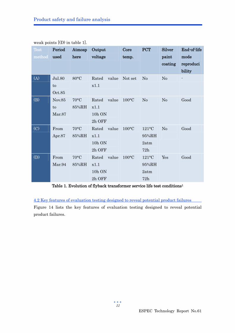
Table 1 summarizes how flyback transformer service life test conditions have evolved.
Since magnet wire service life conforms to Arrhenius law, service life testing initially
only examined ambient temperature, and couldn’t capture the correlation to problems
in the market [(A) in table 1]. When analysis of market failures showed that humidity
was a cause, this factor was added to the test conditions, enabling reproduction of the
destruction mode in the market [(B) table 1]. However, since it took six months to
evaluate reliability under these test conditions, researchers looked for a way to shorten
this time by working with the water absorbency of the insulation plastic. They found
that using a pressure cooker test (PCT) to preprocess the plastic reduced evaluation
time to about one month [(C) in table 1]. The final improvement came when researchers
modeled the deterioration of flyback transformer surface resistance caused by the dust
accumulated and humidity absorbed under actual operating conditions. Researchers
found that coating materials with silver paint is an effective way to detect structurally
Reliability testing designed to reveal potential product failures 4
Product safety and failure analysis
ESPEC Technology Report No.61
11
weak points [(D) in table 1].
Test
method
Period
used
Atmosp
here
Output
voltage
Core
temp.
PCT Silver
paint
coating
End-of-life
mode
reproduci
bility
(A) Jul.80
to
Oct.85
80°C Rated value
x1.1
Not set No No -
(B) Nov.85
to
Mar.87
70°C
85%RH
Rated value
x1.1
10h ON
2h OFF
100°C No No Good
(C) From
Apr.87
70°C
85%RH
Rated value
x1.1
10h ON
2h OFF
100°C 121°C
95%RH
2atm
72h
No
Good
(D) From
Mar.94
70°C
85%RH
Rated value
x1.1
10h ON
2h OFF
100°C 121°C
95%RH
2atm
72h
Yes Good
Table 1. Evolution of flyback transformer service life test conditions1
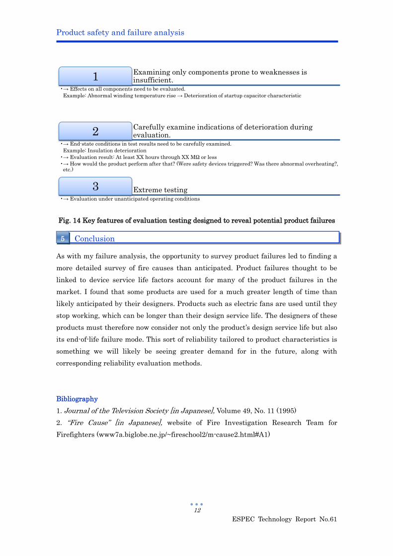
4.2 Key features of evaluation testing designed to reveal potential product failures
Figure 14 lists the key features of evaluation testing designed to reveal potential
product failures.
Product safety and failure analysis
ESPEC Technology Report No.61
12
Examining only components prone to weaknesses is insufficient. 1
•→ Effects on all components need to be evaluated.
Example: Abnormal winding temperature rise → Deterioration of startup capacitor characteristic
Carefully examine indications of deterioration during evaluation. 2
•→ End-state conditions in test results need to be carefully examined.
Example: Insulation deterioration
•→ Evaluation result: At least XX hours through XX MΩ or less
•→ How would the product perform after that? (Were safety devices triggered? Was there abnormal overheating?, etc.)
Extreme testing 3 •→ Evaluation under unanticipated operating conditions
Fig. 14 Key features of evaluation testing designed to reveal potential product failures
As with my failure analysis, the opportunity to survey product failures led to finding a
more detailed survey of fire causes than anticipated. Product failures thought to be
linked to device service life factors account for many of the product failures in the
market. I found that some products are used for a much greater length of time than
likely anticipated by their designers. Products such as electric fans are used until they
stop working, which can be longer than their design service life. The designers of these
products must therefore now consider not only the product’s design service life but also
its end-of-life failure mode. This sort of reliability tailored to product characteristics is
something we will likely be seeing greater demand for in the future, along with
corresponding reliability evaluation methods.
Bibliography
1. Journal of the Television Society [in Japanese], Volume 49, No. 11 (1995)
2. “Fire Cause” [in Japanese], website of Fire Investigation Research Team for
Firefighters (www7a.biglobe.ne.jp/~fireschool2/m-cause2.html#A1)
Conclusion 5