Embed Size (px)
Citation preview
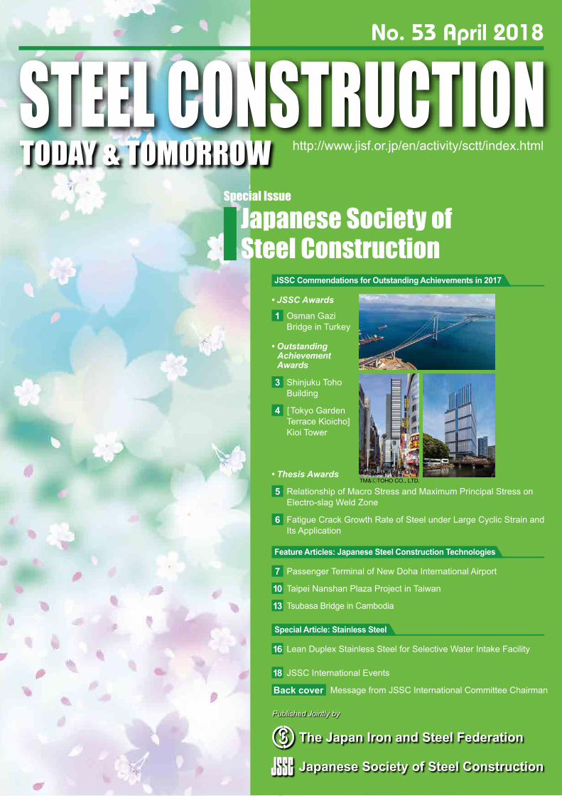
STEEL CONSTRUCTIONTODAY & TOMORROW http://www.jisf.or.jp/en/activity/sctt/index.html
Published Jointly by
No. 53 April 2018
The Japan Iron and Steel Federation
Japanese Society of Steel Construction
TM&ⒸTOHO CO., LTD.
Special Issue
Japanese Society of Steel Construction
Osman Gazi Bridge in Turkey
1• JSSC Awards
[Tokyo Garden Terrace Kioicho] Kioi Tower
4
Shinjuku Toho Building
3
• Outstanding Achievement Awards
Relationship of Macro Stress and Maximum Principal Stress on Electro-slag Weld Zone
5
Fatigue Crack Growth Rate of Steel under Large Cyclic Strain and Its Application
6
• Thesis Awards
JSSC Commendations for Outstanding Achievements in 2017
Passenger Terminal of New Doha International Airport7
Taipei Nanshan Plaza Project in Taiwan10
Tsubasa Bridge in Cambodia13
Feature Articles: Japanese Steel Construction Technologies
Lean Duplex Stainless Steel for Selective Water Intake Facility16
Special Article: Stainless Steel
JSSC International Events18
Message from JSSC International Committee ChairmanBack cover
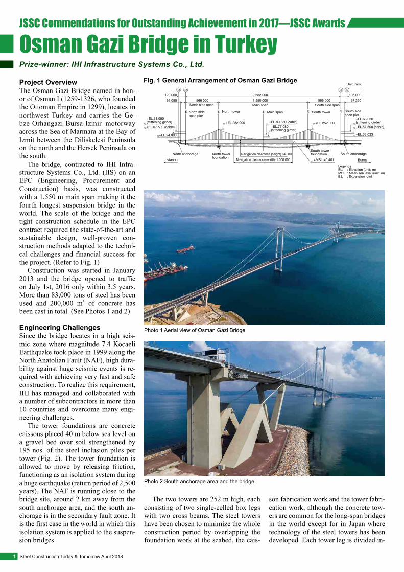
Project OverviewThe Osman Gazi Bridge named in hon-or of Osman I (1259-1326, who founded the Ottoman Empire in 1299), locates in northwest Turkey and carries the Ge-bze-Orhangazi-Bursa-Izmir motorway across the Sea of Marmara at the Bay of Izmit between the Diliskelesi Peninsula on the north and the Hersek Peninsula on the south.
The bridge, contracted to IHI Infra-structure Systems Co., Ltd. (IIS) on an EPC (Engineering, Procurement and Construction) basis, was constructed with a 1,550 m main span making it the fourth longest suspension bridge in the world. The scale of the bridge and the tight construction schedule in the EPC contract required the state-of-the-art and sustainable design, well-proven con-struction methods adapted to the techni-cal challenges and financial success for the project. (Refer to Fig. 1)
Construction was started in January 2013 and the bridge opened to traffic on July 1st, 2016 only within 3.5 years. More than 83,000 tons of steel has been used and 200,000 m3 of concrete has been cast in total. (See Photos 1 and 2)
Engineering ChallengesSince the bridge locates in a high seis-mic zone where magnitude 7.4 Kocaeli Earthquake took place in 1999 along the North Anatolian Fault (NAF), high dura-bility against huge seismic events is re-quired with achieving very fast and safe construction. To realize this requirement, IHI has managed and collaborated with a number of subcontractors in more than 10 countries and overcome many engi-neering challenges.
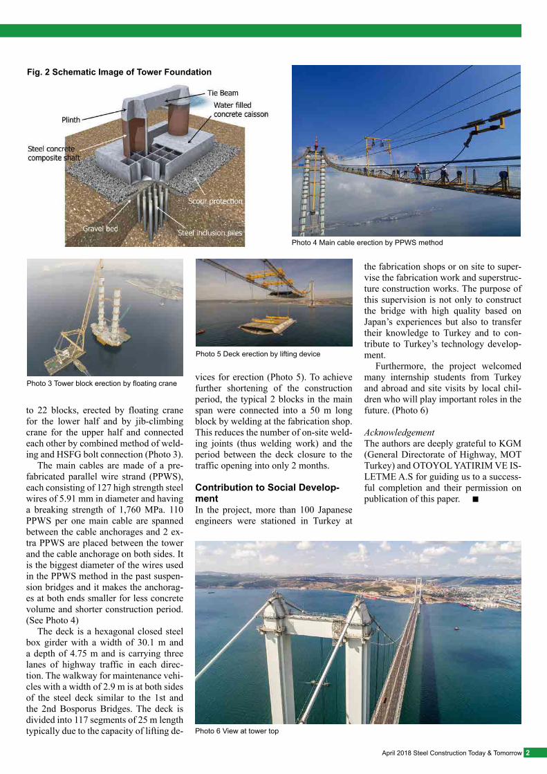
The tower foundations are concrete caissons placed 40 m below sea level on a gravel bed over soil strengthened by 195 nos. of the steel inclusion piles per tower (Fig. 2). The tower foundation is allowed to move by releasing friction, functioning as an isolation system during a huge earthquake (return period of 2,500 years). The NAF is running close to the bridge site, around 2 km away from the south anchorage area, and the south an-chorage is in the secondary fault zone. It is the first case in the world in which this isolation system is applied to the suspen-sion bridges.
The two towers are 252 m high, each consisting of two single-celled box legs with two cross beams. The steel towers have been chosen to minimize the whole construction period by overlapping the foundation work at the seabed, the cais-
son fabrication work and the tower fabri-cation work, although the concrete tow-ers are common for the long-span bridges in the world except for in Japan where technology of the steel towers has been developed. Each tower leg is divided in-
1 Steel Construction Today & Tomorrow April 2018
JSSC Commendations for Outstanding Achievement in 2017—JSSC Awards
Osman Gazi Bridge in TurkeyPrize-winner: IHI Infrastructure Systems Co., Ltd.
Photo 2 South anchorage area and the bridge
Photo 1 Aerial view of Osman Gazi Bridge
120 00092 050
2 682 0001 550 000
105 00067 250566 000
North tower
+EL.252.000
North tower foundation
Main span South side span
Main span
[Unit: mm]
South tower
+EL.80.330 (cable) +EL.252.000
South side span pier
+EL.63.050 (stiffening girder)+EL.57.500 (cable)
+EL.33.023
South anchorageBursa
: Elevation (unit: m): Mean sea level (unit: m): Expansion joint
LegendsEL.MSL.EJ.
+EL.77.080(stiffening girder)
Navigation clearance (height) 64 300South tower foundation
Navigation clearance (width) 1 000 000 +MSL.+0.401
566 000North side span
North side span pier
+EL.63.050 (stiffening girder)+EL.57.500 (cable)
+EL.24.000
North anchorageIstanbul
Fig. 1 General Arrangement of Osman Gazi Bridge
to 22 blocks, erected by floating crane for the lower half and by jib-climbing crane for the upper half and connected each other by combined method of weld-ing and HSFG bolt connection (Photo 3).
The main cables are made of a pre-fabricated parallel wire strand (PPWS), each consisting of 127 high strength steel wires of 5.91 mm in diameter and having a breaking strength of 1,760 MPa. 110 PPWS per one main cable are spanned between the cable anchorages and 2 ex-tra PPWS are placed between the tower and the cable anchorage on both sides. It is the biggest diameter of the wires used in the PPWS method in the past suspen-sion bridges and it makes the anchorag-es at both ends smaller for less concrete volume and shorter construction period. (See Photo 4)
The deck is a hexagonal closed steel box girder with a width of 30.1 m and a depth of 4.75 m and is carrying three lanes of highway traffic in each direc-tion. The walkway for maintenance vehi-cles with a width of 2.9 m is at both sides of the steel deck similar to the 1st and the 2nd Bosporus Bridges. The deck is divided into 117 segments of 25 m length typically due to the capacity of lifting de-
vices for erection (Photo 5). To achieve further shortening of the construction period, the typical 2 blocks in the main span were connected into a 50 m long block by welding at the fabrication shop. This reduces the number of on-site weld-ing joints (thus welding work) and the period between the deck closure to the traffic opening into only 2 months.
Contribution to Social Develop-mentIn the project, more than 100 Japanese engineers were stationed in Turkey at
the fabrication shops or on site to super-vise the fabrication work and superstruc-ture construction works. The purpose of this supervision is not only to construct the bridge with high quality based on Japan’s experiences but also to transfer their knowledge to Turkey and to con-tribute to Turkey’s technology develop-ment.
Furthermore, the project welcomed many internship students from Turkey and abroad and site visits by local chil-dren who will play important roles in the future. (Photo 6)
AcknowledgementThe authors are deeply grateful to KGM (General Directorate of Highway, MOT Turkey) and OTOYOL YATIRIM VE IS-LETME A.S for guiding us to a success-ful completion and their permission on publication of this paper. ■
2April 2018 Steel Construction Today & Tomorrow
Fig. 2 Schematic Image of Tower Foundation
Photo 6 View at tower top
Photo 5 Deck erection by lifting device
Photo 4 Main cable erection by PPWS method
Photo 3 Tower block erection by floating crane
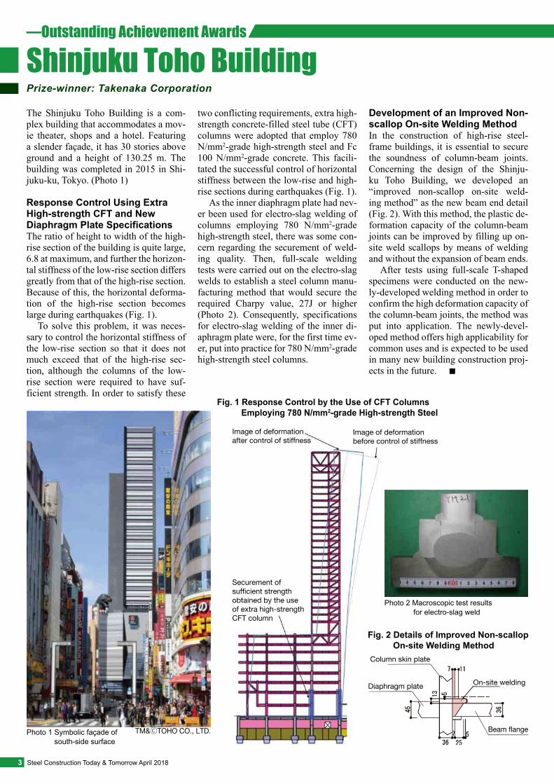
The Shinjuku Toho Building is a com-plex building that accommodates a mov-ie theater, shops and a hotel. Featuring a slender façade, it has 30 stories above ground and a height of 130.25 m. The building was completed in 2015 in Shi-juku-ku, Tokyo. (Photo 1)
Response Control Using Extra High-strength CFT and New Diaphragm Plate SpecificationsThe ratio of height to width of the high-rise section of the building is quite large, 6.8 at maximum, and further the horizon-tal stiffness of the low-rise section differs greatly from that of the high-rise section. Because of this, the horizontal deforma-tion of the high-rise section becomes large during earthquakes (Fig. 1).
To solve this problem, it was neces-sary to control the horizontal stiffness of the low-rise section so that it does not much exceed that of the high-rise sec-tion, although the columns of the low-rise section were required to have suf-ficient strength. In order to satisfy these
two conflicting requirements, extra high-strength concrete-filled steel tube (CFT) columns were adopted that employ 780 N/mm2-grade high-strength steel and Fc 100 N/mm2-grade concrete. This facili-tated the successful control of horizontal stiffness between the low-rise and high-rise sections during earthquakes (Fig. 1).
As the inner diaphragm plate had nev-er been used for electro-slag welding of columns employing 780 N/mm2-grade high-strength steel, there was some con-cern regarding the securement of weld-ing quality. Then, full-scale welding tests were carried out on the electro-slag welds to establish a steel column manu-facturing method that would secure the required Charpy value, 27J or higher (Photo 2). Consequently, specifications for electro-slag welding of the inner di-aphragm plate were, for the first time ev-er, put into practice for 780 N/mm2-grade high-strength steel columns.
Development of an Improved Non-scallop On-site Welding MethodIn the construction of high-rise steel-frame buildings, it is essential to secure the soundness of column-beam joints. Concerning the design of the Shinju-ku Toho Building, we developed an “improved non-scallop on-site weld-ing method” as the new beam end detail (Fig. 2). With this method, the plastic de-formation capacity of the column-beam joints can be improved by filling up on-site weld scallops by means of welding and without the expansion of beam ends.
After tests using full-scale T-shaped specimens were conducted on the new-ly-developed welding method in order to confirm the high deformation capacity of the column-beam joints, the method was put into application. The newly-devel-oped method offers high applicability for common uses and is expected to be used in many new building construction proj-ects in the future. ■
3 Steel Construction Today & Tomorrow April 2018
Securement of sufficient strength obtained by the use of extra high-strength CFT column
Image of deformation after control of stiffness
Image of deformation before control of stiffness
Fig. 1 Response Control by the Use of CFT Columns Employing 780 N/mm2-grade High-strength Steel
TM&ⒸTOHO CO., LTD.
—Outstanding Achievement Awards
Shinjuku Toho BuildingPrize-winner: Takenaka Corporation
Photo 2 Macroscopic test results for electro-slag weld
Photo 1 Symbolic façade of south-side surface
Column skin plate
Diaphragm plate On-site welding
Beam flange
Fig. 2 Details of Improved Non-scallop On-site Welding Method
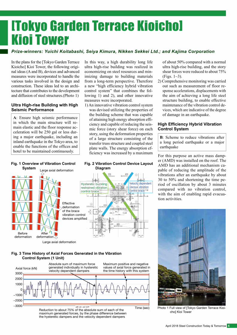
In the plans for the [Tokyo Garden Terrace Kioicho] Kioi Tower, the following origi-nal ideas (A and B), devices and advanced measures were incorporated to handle the various tasks involved in the design and construction. These ideas led to an archi-tecture that contributes to the development and diffusion of steel structures.(Photo 1)
Ultra High-rise Building with High Seismic Performance
In this way, a high durability long life ultra high-rise building was realized in economizing on steel resources and min-imizing damage to building materials from a long-term perspective. Therefore a new “high efficiency hybrid vibration control system” that combines the fol-lowing 1) and 2), and other innovative measures were incorporated.1) An innovative vibration control system
was devised utilizing the properties of the building scheme that was capable of attaining high energy absorption effi-ciency and capable of reducing the seis-mic force (story shear force) on each story, using the deformation properties of a large structure consisting of the transfer truss structure and coupled steel plate walls. The energy absorption ef-ficiency was increased by a maximum
A: Ensure high seismic performance in which the main structure will re-main elastic and the floor response ac-celeration will be 250 gal or less dur-ing a major earthquake, including an inland earthquake in the Tokyo area, to enable the functions of the offices and hotel to be maintained continuously.
For this purpose an active mass damp-er (AMD) was installed on the roof. The AMD has an additional mechanism ca-pable of reducing the amplitude of the vibrations after an earthquake by about 30 to 50% and shortening the time pe-riod of oscillation by about 3 minutes compared with no vibration control, with the aim of enabling rapid evacua-tion activities.
B: Scheme to reduce vibrations after a long period earthquake or a major earthquake
Hysteretic buckling restrained vibration control brace
Hysteretic buckling restrained vibration control brace
Velocity dependent viscous vibration control brace
Velocity dependent viscous vibration control brace
Before deformation
After deformation
Large axial deformation
Effective deformation of the brace vibration control devices amplified
Large axial deformation
Fig. 1 Overview of Vibration Control System
Fig. 2 Vibration Control Device Layout Diagram
of about 50% compared with a normal ultra high-rise building, and the story shear forces were reduced to about 75% (Figs. 1~3).
2) Comprehensive monitoring was carried out such as measurement of floor re-sponse accelerations, displacements with the aim of achieving a long life steel structure building, to enable effective maintenance of the vibration control de-vices, which are indicative of the degree of damage in an earthquake.
High Efficiency Hybrid Vibration Control System
Absolute sum of maximum force generated individually in hysteretic velocity dependent dampers
Axial force (kN)300020001000
0−1000−2000−3000 Time (sec)Reduction to about 75% of the absolute sum of each of the
maximum generated forces, by the phase difference between the hysteretic dampers and the velocity dependent dampers
Maximum positive and negative values of axial force generated in the time history with this system
Fig. 3 Time History of Axial Forces Generated in the Vibration Control System (1 Unit)
4April 2018 Steel Construction Today & Tomorrow
Prize-winners: Yuichi Koitabashi, Seiya Kimura, Nikken Sekkei Ltd.; and Kajima Corporation
Photo 1 Full view of [Tokyo Garden Terrace Kioi-cho] Kioi Tower
[Tokyo Garden Terrace Kioicho] Kioi Tower
5 Steel Construction Today & Tomorrow April 2018
—Thesis Awards
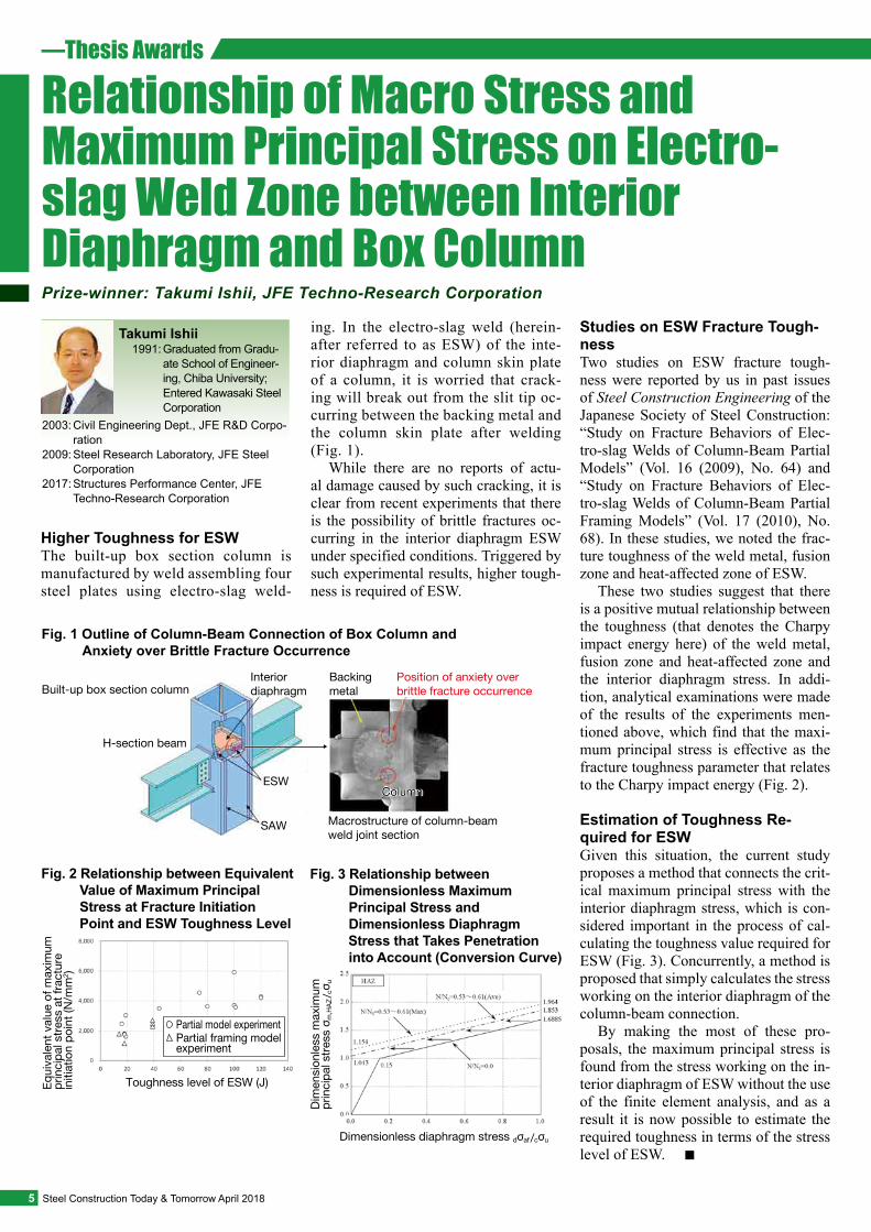
Relationship of Macro Stress and Maximum Principal Stress on Electro-slag Weld Zone between Interior Diaphragm and Box Column
Higher Toughness for ESWThe built-up box section column is manufactured by weld assembling four steel plates using electro-slag weld-
ing. In the electro-slag weld (herein-after referred to as ESW) of the inte-rior diaphragm and column skin plate of a column, it is worried that crack-ing will break out from the slit tip oc-curring between the backing metal and the column skin plate after welding (Fig. 1).
While there are no reports of actu-al damage caused by such cracking, it is clear from recent experiments that there is the possibility of brittle fractures oc-curring in the interior diaphragm ESW under specified conditions. Triggered by such experimental results, higher tough-ness is required of ESW.
Studies on ESW Fracture Tough-nessTwo studies on ESW fracture tough-ness were reported by us in past issues of Steel Construction Engineering of the Japanese Society of Steel Construction: “Study on Fracture Behaviors of Elec-tro-slag Welds of Column-Beam Partial Models” (Vol. 16 (2009), No. 64) and “Study on Fracture Behaviors of Elec-tro-slag Welds of Column-Beam Partial Framing Models” (Vol. 17 (2010), No. 68). In these studies, we noted the frac-ture toughness of the weld metal, fusion zone and heat-affected zone of ESW.
These two studies suggest that there is a positive mutual relationship between the toughness (that denotes the Charpy impact energy here) of the weld metal, fusion zone and heat-affected zone and the interior diaphragm stress. In addi-tion, analytical examinations were made of the results of the experiments men-tioned above, which find that the maxi-mum principal stress is effective as the fracture toughness parameter that relates to the Charpy impact energy (Fig. 2).
Estimation of Toughness Re-quired for ESWGiven this situation, the current study proposes a method that connects the crit-ical maximum principal stress with the interior diaphragm stress, which is con-sidered important in the process of cal-culating the toughness value required for ESW (Fig. 3). Concurrently, a method is proposed that simply calculates the stress working on the interior diaphragm of the column-beam connection.
By making the most of these pro-posals, the maximum principal stress is found from the stress working on the in-terior diaphragm of ESW without the use of the finite element analysis, and as a result it is now possible to estimate the required toughness in terms of the stress level of ESW. ■
Prize-winner: Takumi Ishii, JFE Techno-Research Corporation
Toughness level of ESW (J) Equi
vale
nt v
alue
of m
axim
um
prin
cipa
l stre
ss a
t fra
ctur
e in
itiat
ion
poin
t (N
/mm
2 )
Fig. 2 Relationship between Equivalent Value of Maximum Principal Stress at Fracture Initiation Point and ESW Toughness Level
Partial framing model experiment
Partial model experiment
1991: Graduated from Gradu-ate School of Engineer-ing, Chiba University; Entered Kawasaki Steel Corporation
2003:
2009:
2017:
Civil Engineering Dept., JFE R&D Corpo-rationSteel Research Laboratory, JFE Steel CorporationStructures Performance Center, JFE Techno-Research Corporation
Takumi Ishii
Built-up box section columnInterior diaphragm
Backing metal
Position of anxiety over brittle fracture occurrence
ColumnColumn
Macrostructure of column-beam weld joint section
ESW
SAW
H-section beam
Fig. 1 Outline of Column-Beam Connection of Box Column and Anxiety over Brittle Fracture Occurrence
Dimensionless diaphragm stress dσaf /cσu
Dim
ensi
onle
ss m
axim
um
prin
cipa
l stre
ss σ
m,H
AZ/ cσ
u
Fig. 3 Relationship between Dimensionless Maximum Principal Stress and Dimensionless Diaphragm Stress that Takes Penetration into Account (Conversion Curve)
6April 2018 Steel Construction Today & Tomorrow
Fatigue Crack Growth Rate of Steel under Large Cyclic Strain and Its Application to Crack Growth Prediction in Welded Joints
Low cycle fatigue is one of the failure modes in steel structures during earth-quakes. With a focus on crack growth in the low cycle fatigue region, this study developed a fatigue crack growth curve, and verified its applicability to crack growth prediction in welded joints.
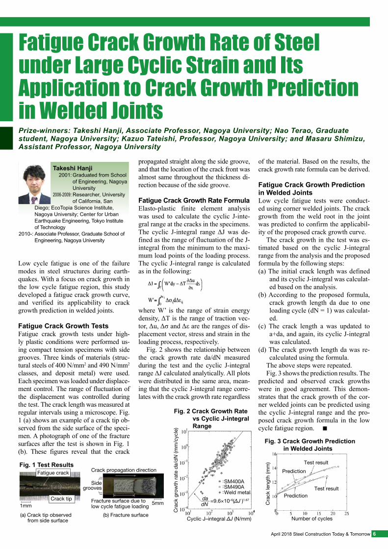
Fatigue Crack Growth TestsFatigue crack growth tests under high-ly plastic conditions were performed us-ing compact tension specimens with side grooves. Three kinds of materials (struc-tural steels of 400 N/mm2 and 490 N/mm2 classes, and deposit metal) were used. Each specimen was loaded under displace-ment control. The range of fluctuation of the displacement was controlled during the test. The crack length was measured at regular intervals using a microscope. Fig. 1 (a) shows an example of a crack tip ob-served from the side surface of the speci-men. A photograph of one of the fracture surfaces after the test is shown in Fig. 1 (b). These figures reveal that the crack
propagated straight along the side groove, and that the location of the crack front was almost same throughout the thickness di-rection because of the side groove.
Fatigue Crack Growth Rate Formula Elasto-plastic finite element analysis was used to calculate the cyclic J-inte-gral range at the cracks in the specimens. The cyclic J-integral range ΔJ was de-fined as the range of fluctuation of the J-integral from the minimum to the maxi-mum load points of the loading process. The cyclic J-integral range is calculated as in the following:
where W’ is the range of strain energy density, ΔT is the range of traction vec-tor, Δu, Δσ and Δε are the ranges of dis-placement vector, stress and strain in the loading process, respectively.
Fig. 2 shows the relationship between the crack growth rate da/dN measured during the test and the cyclic J-integral range ΔJ calculated analytically. All plots were distributed in the same area, mean-ing that the cyclic J-integral range corre-lates with the crack growth rate regardless
of the material. Based on the results, the crack growth rate formula can be derived.
Fatigue Crack Growth Prediction in Welded JointsLow cycle fatigue tests were conduct-ed using corner welded joints. The crack growth from the weld root in the joint was predicted to confirm the applicabil-ity of the proposed crack growth curve.
The crack growth in the test was es-timated based on the cyclic J-integral range from the analysis and the proposed formula by the following steps: (a) The initial crack length was defined
and its cyclic J-integral was calculat-ed based on the analysis.
(b) According to the proposed formula, crack growth length da due to one loading cycle (dN = 1) was calculat-ed.
(c) The crack length a was updated to a+da, and again, its cyclic J-integral was calculated.
(d) The crack growth length da was re-calculated using the formula.
The above steps were repeated.Fig. 3 shows the prediction results. The
predicted and observed crack growths were in good agreement. This demon-strates that the crack growth of the cor-ner welded joints can be predicted using the cyclic J-integral range and the pro-posed crack growth formula in the low cycle fatigue region. ■
Prize-winners: Takeshi Hanji, Associate Professor, Nagoya University; Nao Terao, Graduate student, Nagoya University; Kazuo Tateishi, Professor, Nagoya University; and Masaru Shimizu, Assistant Professor, Nagoya University
Number of cycles
PredictionTest result
Test resultPrediction
Cra
ck le
ngth
(mm
)
Fig. 3 Crack Growth Prediction in Welded Joints
2001:
2006-2009:
Graduated from School of Engineering, Nagoya UniversityResearcher, University of California, San
2010-:
Diego; EcoTopia Science Institute, Nagoya University; Center for Urban Earthquake Engineering, Tokyo Institute of TechnologyAssociate Professor, Graduate School of Engineering, Nagoya University
Takeshi Hanji
(a) Crack tip observed from side surface
1mmCrack tip
Sidegrooves
Fracture surface due tolow cycle fatigue loading 5mm
Crack propagation direction
(b) Fracture surface
Fig. 1 Test ResultsFatigue crack
Cyclic J–integral ΔJ (N/mm)
SM400ASM490AWeld metal
Cra
ck g
row
th ra
te d
a/dN
(mm
/cyc
le)
Fig. 2 Crack Growth Rate vs Cyclic J-integral Range
=9.6×10⁻⁶(ΔJ )1.67dadN
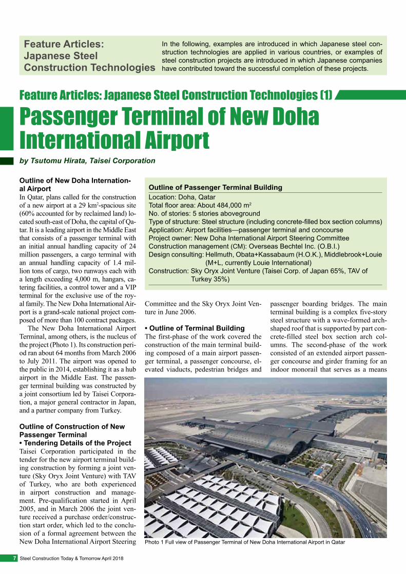
Outline of New Doha Internation-al AirportIn Qatar, plans called for the construction of a new airport at a 29 km2-spacious site (60% accounted for by reclaimed land) lo-cated south-east of Doha, the capital of Qa-tar. It is a leading airport in the Middle East that consists of a passenger terminal with an initial annual handling capacity of 24 million passengers, a cargo terminal with an annual handling capacity of 1.4 mil-lion tons of cargo, two runways each with a length exceeding 4,000 m, hangars, ca-tering facilities, a control tower and a VIP terminal for the exclusive use of the roy-al family. The New Doha International Air-port is a grand-scale national project com-posed of more than 100 contract packages.
The New Doha International Airport Terminal, among others, is the nucleus of the project (Photo 1). Its construction peri-od ran about 64 months from March 2006 to July 2011. The airport was opened to the public in 2014, establishing it as a hub airport in the Middle East. The passen-ger terminal building was constructed by a joint consortium led by Taisei Corpora-tion, a major general contractor in Japan, and a partner company from Turkey.
Outline of Construction of New Passenger Terminal• Tendering Details of the Project Taisei Corporation participated in the tender for the new airport terminal build-ing construction by forming a joint ven-ture (Sky Oryx Joint Venture) with TAV of Turkey, who are both experienced in airport construction and manage-ment. Pre-qualification started in April 2005, and in March 2006 the joint ven-ture received a purchase order/construc-tion start order, which led to the conclu-sion of a formal agreement between the New Doha International Airport Steering
Committee and the Sky Oryx Joint Ven-ture in June 2006.
• Outline of Terminal Building The first-phase of the work covered the construction of the main terminal build-ing composed of a main airport passen-ger terminal, a passenger concourse, el-evated viaducts, pedestrian bridges and
passenger boarding bridges. The main terminal building is a complex five-story steel structure with a wave-formed arch-shaped roof that is supported by part con-crete-filled steel box section arch col-umns. The second-phase of the work consisted of an extended airport passen-ger concourse and girder framing for an indoor monorail that serves as a means
In the following, examples are introduced in which Japanese steel con-struction technologies are applied in various countries, or examples of steel construction projects are introduced in which Japanese companies have contributed toward the successful completion of these projects.
Outline of Passenger Terminal BuildingLocation: Doha, QatarTotal floor area: About 484,000 m2
No. of stories: 5 stories abovegroundType of structure: Steel structure (including concrete-filled box section columns)Application: Airport facilities—passenger terminal and concourseProject owner: New Doha International Airport Steering CommitteeConstruction management (CM): Overseas Bechtel Inc. (O.B.I.)Design consulting: Hellmuth, Obata+Kassabaum (H.O.K.), Middlebrook+Louie (M+L, currently Louie International)Construction: Sky Oryx Joint Venture (Taisei Corp. of Japan 65%, TAV of Turkey 35%)
by Tsutomu Hirata, Taisei Corporation
Passenger Terminal of New Doha International Airport
Feature Articles: Japanese Steel Construction Technologies
Feature Articles: Japanese Steel Construction Technologies (1)
7 Steel Construction Today & Tomorrow April 2018
Photo 1 Full view of Passenger Terminal of New Doha International Airport in Qatar
Step 1: Installation and welding of arch column steel framing
Step 5: Concrete filling of square steel box section columns
Step 6: Jacking down and dismantling of bent
Step 4: Installation, bolting and welding of steel framing for main building
Step 2: Installation, bolting and welding of arch steel framing
Step 3: Column base mortar placement
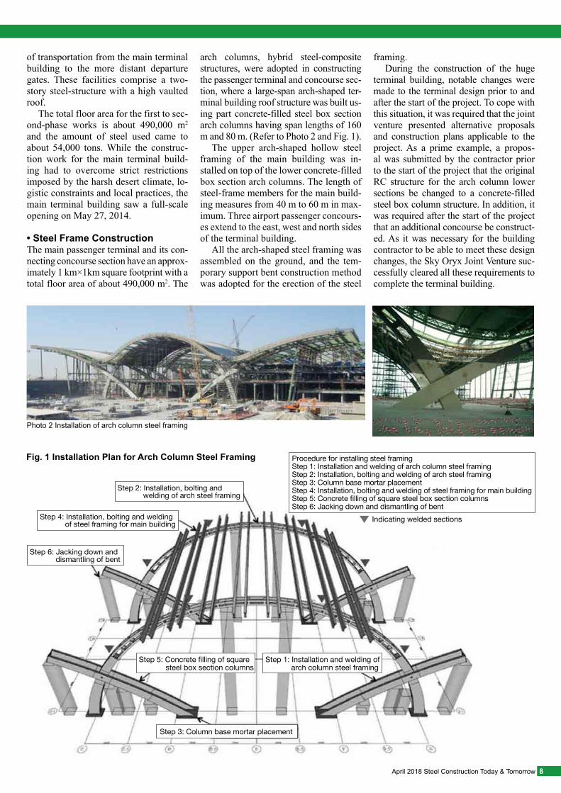
Procedure for installing steel framingStep 1: Installation and welding of arch column steel framingStep 2: Installation, bolting and welding of arch steel framingStep 3: Column base mortar placementStep 4: Installation, bolting and welding of steel framing for main buildingStep 5: Concrete filling of square steel box section columnsStep 6: Jacking down and dismantling of bent
Indicating welded sections
Fig. 1 Installation Plan for Arch Column Steel Framing
of transportation from the main terminal building to the more distant departure gates. These facilities comprise a two-story steel-structure with a high vaulted roof.
The total floor area for the first to sec-ond-phase works is about 490,000 m2
and the amount of steel used came to about 54,000 tons. While the construc-tion work for the main terminal build-ing had to overcome strict restrictions imposed by the harsh desert climate, lo-gistic constraints and local practices, the main terminal building saw a full-scale opening on May 27, 2014.
• Steel Frame ConstructionThe main passenger terminal and its con-necting concourse section have an approx-imately 1 km×1km square footprint with a total floor area of about 490,000 m2. The
arch columns, hybrid steel-composite structures, were adopted in constructing the passenger terminal and concourse sec-tion, where a large-span arch-shaped ter-minal building roof structure was built us-ing part concrete-filled steel box section arch columns having span lengths of 160 m and 80 m. (Refer to Photo 2 and Fig. 1).
The upper arch-shaped hollow steel framing of the main building was in-stalled on top of the lower concrete-filled box section arch columns. The length of steel-frame members for the main build-ing measures from 40 m to 60 m in max-imum. Three airport passenger concours-es extend to the east, west and north sides of the terminal building.
All the arch-shaped steel framing was assembled on the ground, and the tem-porary support bent construction method was adopted for the erection of the steel
framing.During the construction of the huge
terminal building, notable changes were made to the terminal design prior to and after the start of the project. To cope with this situation, it was required that the joint venture presented alternative proposals and construction plans applicable to the project. As a prime example, a propos-al was submitted by the contractor prior to the start of the project that the original RC structure for the arch column lower sections be changed to a concrete-filled steel box column structure. In addition, it was required after the start of the project that an additional concourse be construct-ed. As it was necessary for the building contractor to be able to meet these design changes, the Sky Oryx Joint Venture suc-cessfully cleared all these requirements to complete the terminal building.
8April 2018 Steel Construction Today & Tomorrow
Photo 2 Installation of arch column steel framing
Collaborative System between Engineers from Many CountriesIn this airport terminal project, as an out-standingly large-scale construction proj-ect to be undertaken in the Middle Eastern country of Qatar, it was considered nec-essary to establish a multinational collab-orative system for those working on the project in order to build it efficiently.
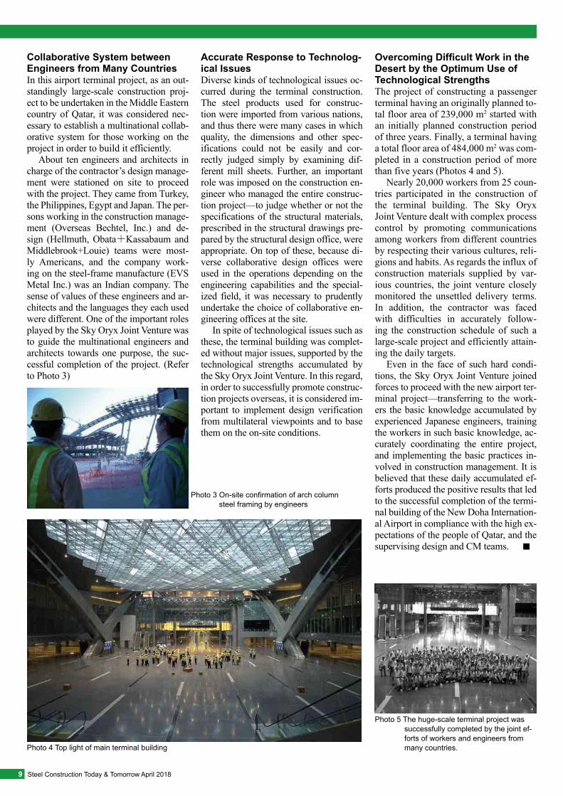
About ten engineers and architects in charge of the contractor’s design manage-ment were stationed on site to proceed with the project. They came from Turkey, the Philippines, Egypt and Japan. The per-sons working in the construction manage-ment (Overseas Bechtel, Inc.) and de-sign (Hellmuth, Obata+Kassabaum and Middlebrook+Louie) teams were most-ly Americans, and the company work-ing on the steel-frame manufacture (EVS Metal Inc.) was an Indian company. The sense of values of these engineers and ar-chitects and the languages they each used were different. One of the important roles played by the Sky Oryx Joint Venture was to guide the multinational engineers and architects towards one purpose, the suc-cessful completion of the project. (Refer to Photo 3)
Accurate Response to Technolog-ical IssuesDiverse kinds of technological issues oc-curred during the terminal construction. The steel products used for construc-tion were imported from various nations, and thus there were many cases in which quality, the dimensions and other spec-ifications could not be easily and cor-rectly judged simply by examining dif-ferent mill sheets. Further, an important role was imposed on the construction en-gineer who managed the entire construc-tion project—to judge whether or not the specifications of the structural materials, prescribed in the structural drawings pre-pared by the structural design office, were appropriate. On top of these, because di-verse collaborative design offices were used in the operations depending on the engineering capabilities and the special-ized field, it was necessary to prudently undertake the choice of collaborative en-gineering offices at the site.
In spite of technological issues such as these, the terminal building was complet-ed without major issues, supported by the technological strengths accumulated by the Sky Oryx Joint Venture. In this regard, in order to successfully promote construc-tion projects overseas, it is considered im-portant to implement design verification from multilateral viewpoints and to base them on the on-site conditions.
Overcoming Difficult Work in the Desert by the Optimum Use of Technological StrengthsThe project of constructing a passenger terminal having an originally planned to-tal floor area of 239,000 m2 started with an initially planned construction period of three years. Finally, a terminal having a total floor area of 484,000 m2 was com-pleted in a construction period of more than five years (Photos 4 and 5).
Nearly 20,000 workers from 25 coun-tries participated in the construction of the terminal building. The Sky Oryx Joint Venture dealt with complex process control by promoting communications among workers from different countries by respecting their various cultures, reli-gions and habits. As regards the influx of construction materials supplied by var-ious countries, the joint venture closely monitored the unsettled delivery terms. In addition, the contractor was faced with difficulties in accurately follow-ing the construction schedule of such a large-scale project and efficiently attain-ing the daily targets.
Even in the face of such hard condi-tions, the Sky Oryx Joint Venture joined forces to proceed with the new airport ter-minal project—transferring to the work-ers the basic knowledge accumulated by experienced Japanese engineers, training the workers in such basic knowledge, ac-curately coordinating the entire project, and implementing the basic practices in-volved in construction management. It is believed that these daily accumulated ef-forts produced the positive results that led to the successful completion of the termi-nal building of the New Doha Internation-al Airport in compliance with the high ex-pectations of the people of Qatar, and the supervising design and CM teams. ■
9 Steel Construction Today & Tomorrow April 2018
Photo 3 On-site confirmation of arch column steel framing by engineers
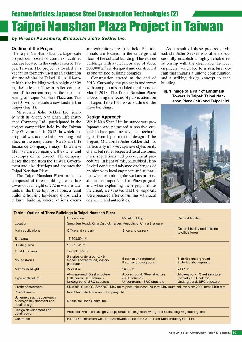
Photo 4 Top light of main terminal building
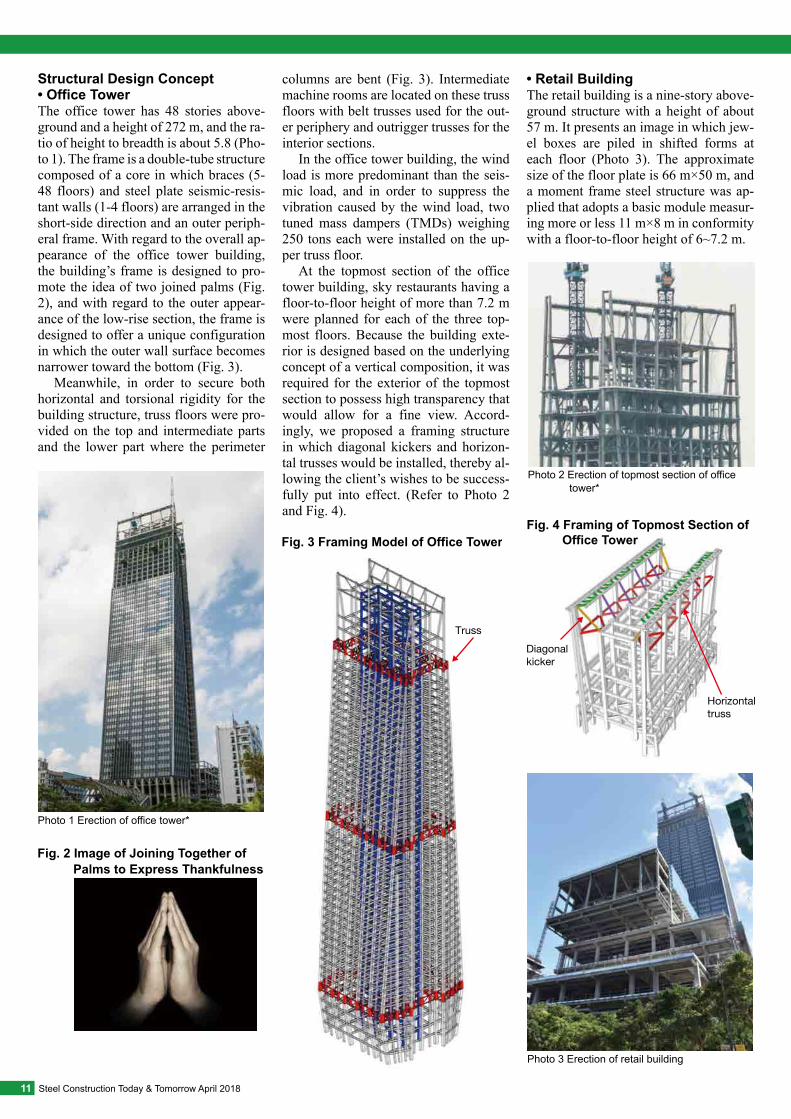
Photo 5 The huge-scale terminal project was successfully completed by the joint ef-forts of workers and engineers from many countries.
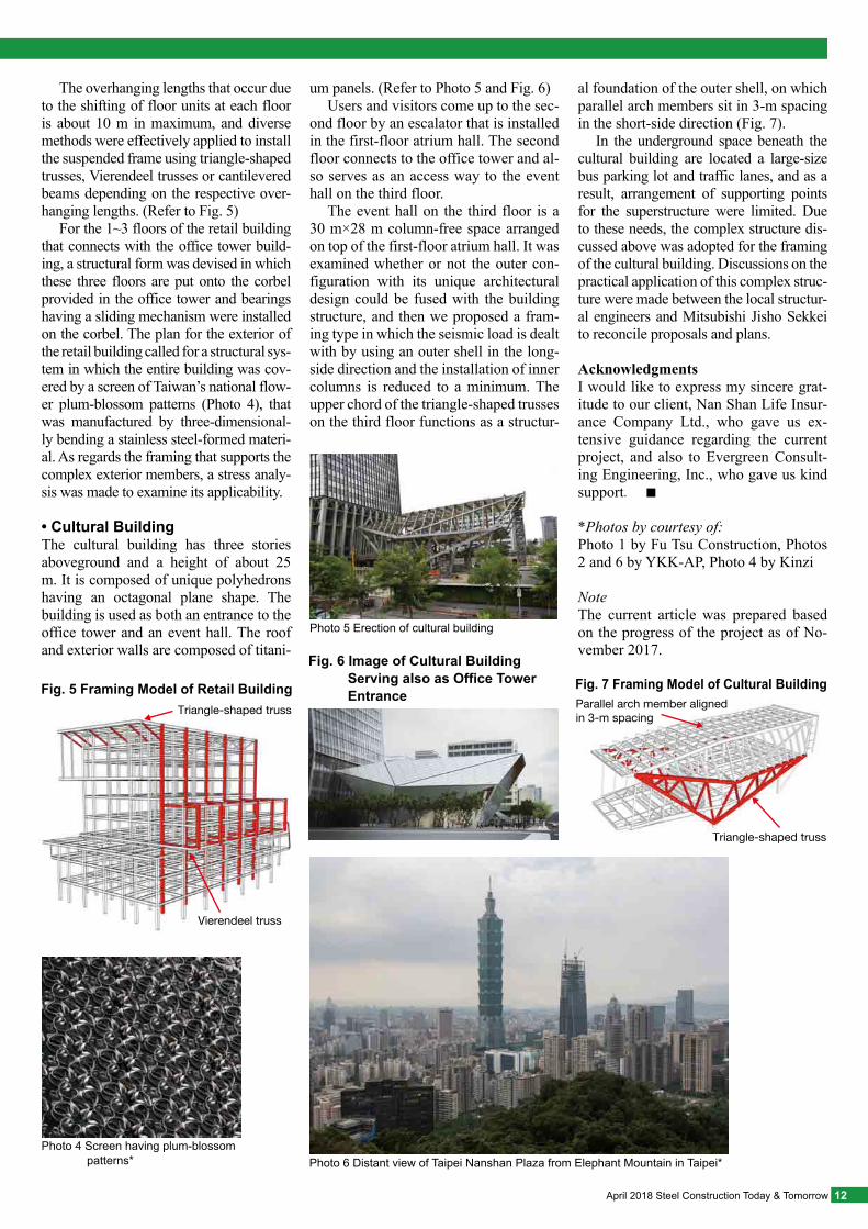
Outline of the ProjectThe Taipei Nanshan Plaza is a large-scale project composed of complex facilities that are located in the central area of Tai-pei, Taiwan. The project is located at a vacant lot formerly used as an exhibition site and adjoins the Taipei 101, a 101-sto-ry high-rise building with a height of 509 m, the tallest in Taiwan. After comple-tion of the current project, the pair con-sisting of Taipei Nanshan Plaza and Tai-pei 101 will constitute a new landmark in Taipei (Fig. 1).
Mitsubishi Jisho Sekkei Inc. joint-ly with its client, Nan Shan Life Insur-ance Company Ltd., participated in the project competition held by the Taiwan City Government in 2012, in which our proposal was adopted after winning first place in the competition. Nan Shan Life Insurance Company, a major Taiwanese life insurance company, is the owner and developer of the project. The company leases the land from the Taiwan Govern-ment and also develops and operates the Taipei Nanshan Plaza.
The Taipei Nanshan Plaza project is composed of three buildings: an office tower with a height of 272 m with restau-rants in the three topmost floors, a retail building housing top-brand shops, and a cultural building where various events
and exhibitions are to be held. Bus ter-minals are located in the underground floor of the cultural building. These three buildings with a total floor area of about 200,000 m2 are designed and constructed as one unified building complex.
Construction started at the end of 2013. Currently, the project is underway with completion scheduled for the end of March 2018. The Taipei Nanshan Plaza is becoming the focus of public attention in Taipei. Table 1 shows an outline of the three buildings.
Design ApproachWhile Nan Shan Life Insurance was pro-Japanese and possessed a positive out-look in incorporating advanced technol-ogies from Japan into the design of the project, Mitsubishi Jisho Sekkei did not particularly impose Japanese styles on its client, but rather respected local customs, laws, regulations and procurement pro-cedures. In light of this, Mitsubishi Jisho Sekkei conducted advance exchanges of opinion with local engineers and authori-ties when examining the various propos-als for the Taipei Nanshan Plaza project, and when explaining these proposals to the client, we stressed that the proposals were prepared after consulting with local engineers and authorities.
As a result of these processes, Mi-tsubishi Jisho Sekkei was able to suc-cessfully establish a highly reliable re-lationship with the client and the local engineers, which led to a structural de-sign that imparts a unique configuration and a striking design concept to each building.
Feature Articles: Japanese Steel Construction Technologies (2)
Taipei Nanshan Plaza Project in Taiwan
10April 2018 Steel Construction Today & Tomorrow
Fig. 1 Image of a Pair of Landmark Towers in Taipei: Taipei Nan-shan Plaza (left) and Taipei 101
Table 1 Outline of Three Buildings in Taipei Nanshan Plaza
Design development and detail design Architect: Archasia Design Group; Structural engineer: Evergreen Consulting Engineering, Inc.
Contractor Fu Tsu Construction Co., Ltd.; Steelwork fabricator: Chun Yuan Steel Industry Co., Ltd.
Location Sung Jen Road, Xinyi District, Taipei, Republic of China (Taiwan)
Site area 17,708.00 m2
Building area 10,271.41 m2
Total floor area 192,891.35 m2
Grade of steelwork SN490B, SN490C, SM570C; Maximum plate thickness: 70 mm; Maximum column size: 2000 mm×1400 mmProject owner Nan Shan Life Insurance Company Ltd.Scheme design/Supervision of design development and detail design
Mitsubishi Jisho Sekkei Inc.
No. of stories5 stories underground, 48 stories aboveground, 2-story penthouse
5 stories underground, 9 stories aboveground
5 stories underground, 3 stories aboveground
Maximum height 272.00 m 56.75 m 24.61 m
Type of structureAboveground: Steel structure (~36 floors: CFT column)Underground: SRC structure
Aboveground: Steel structure (CFT column)Underground: SRC structure
Aboveground: Steel structure (partially CFT column)Underground: SRC structure
Main applications Office and carpark Shop and carpark Cultural facility and entrance to office tower
Office tower Retail building Cultural building
by Hiroshi Kawamura, Mitsubishi Jisho Sekkei Inc.
Structural Design Concept• Office Tower The office tower has 48 stories above-ground and a height of 272 m, and the ra-tio of height to breadth is about 5.8 (Pho-to 1). The frame is a double-tube structure composed of a core in which braces (5-48 floors) and steel plate seismic-resis-tant walls (1-4 floors) are arranged in the short-side direction and an outer periph-eral frame. With regard to the overall ap-pearance of the office tower building, the building’s frame is designed to pro-mote the idea of two joined palms (Fig. 2), and with regard to the outer appear-ance of the low-rise section, the frame is designed to offer a unique configuration in which the outer wall surface becomes narrower toward the bottom (Fig. 3).
Meanwhile, in order to secure both horizontal and torsional rigidity for the building structure, truss floors were pro-vided on the top and intermediate parts and the lower part where the perimeter
columns are bent (Fig. 3). Intermediate machine rooms are located on these truss floors with belt trusses used for the out-er periphery and outrigger trusses for the interior sections.
In the office tower building, the wind load is more predominant than the seis-mic load, and in order to suppress the vibration caused by the wind load, two tuned mass dampers (TMDs) weighing 250 tons each were installed on the up-per truss floor.
At the topmost section of the office tower building, sky restaurants having a floor-to-floor height of more than 7.2 m were planned for each of the three top-most floors. Because the building exte-rior is designed based on the underlying concept of a vertical composition, it was required for the exterior of the topmost section to possess high transparency that would allow for a fine view. Accord-ingly, we proposed a framing structure in which diagonal kickers and horizon-tal trusses would be installed, thereby al-lowing the client’s wishes to be success-fully put into effect. (Refer to Photo 2 and Fig. 4).
• Retail BuildingThe retail building is a nine-story above-ground structure with a height of about 57 m. It presents an image in which jew-el boxes are piled in shifted forms at each floor (Photo 3). The approximate size of the floor plate is 66 m×50 m, and a moment frame steel structure was ap-plied that adopts a basic module measur-ing more or less 11 m×8 m in conformity with a floor-to-floor height of 6~7.2 m.
Diagonal kicker
Horizontal truss
Fig. 4 Framing of Topmost Section of Office Tower
Truss
Fig. 3 Framing Model of Office Tower
11 Steel Construction Today & Tomorrow April 2018
Photo 1 Erection of office tower*
Photo 2 Erection of topmost section of office tower*
Photo 3 Erection of retail building
Fig. 2 Image of Joining Together of Palms to Express Thankfulness
The overhanging lengths that occur due to the shifting of floor units at each floor is about 10 m in maximum, and diverse methods were effectively applied to install the suspended frame using triangle-shaped trusses, Vierendeel trusses or cantilevered beams depending on the respective over-hanging lengths. (Refer to Fig. 5)
For the 1~3 floors of the retail building that connects with the office tower build-ing, a structural form was devised in which these three floors are put onto the corbel provided in the office tower and bearings having a sliding mechanism were installed on the corbel. The plan for the exterior of the retail building called for a structural sys-tem in which the entire building was cov-ered by a screen of Taiwan’s national flow-er plum-blossom patterns (Photo 4), that was manufactured by three-dimensional-ly bending a stainless steel-formed materi-al. As regards the framing that supports the complex exterior members, a stress analy-sis was made to examine its applicability.
• Cultural BuildingThe cultural building has three stories aboveground and a height of about 25 m. It is composed of unique polyhedrons having an octagonal plane shape. The building is used as both an entrance to the office tower and an event hall. The roof and exterior walls are composed of titani-
al foundation of the outer shell, on which parallel arch members sit in 3-m spacing in the short-side direction (Fig. 7).
In the underground space beneath the cultural building are located a large-size bus parking lot and traffic lanes, and as a result, arrangement of supporting points for the superstructure were limited. Due to these needs, the complex structure dis-cussed above was adopted for the framing of the cultural building. Discussions on the practical application of this complex struc-ture were made between the local structur-al engineers and Mitsubishi Jisho Sekkei to reconcile proposals and plans.
AcknowledgmentsI would like to express my sincere grat-itude to our client, Nan Shan Life Insur-ance Company Ltd., who gave us ex-tensive guidance regarding the current project, and also to Evergreen Consult-ing Engineering, Inc., who gave us kind support. ■
*Photos by courtesy of:Photo 1 by Fu Tsu Construction, Photos 2 and 6 by YKK-AP, Photo 4 by Kinzi
NoteThe current article was prepared based on the progress of the project as of No-vember 2017.
um panels. (Refer to Photo 5 and Fig. 6)Users and visitors come up to the sec-
ond floor by an escalator that is installed in the first-floor atrium hall. The second floor connects to the office tower and al-so serves as an access way to the event hall on the third floor.
The event hall on the third floor is a 30 m×28 m column-free space arranged on top of the first-floor atrium hall. It was examined whether or not the outer con-figuration with its unique architectural design could be fused with the building structure, and then we proposed a fram-ing type in which the seismic load is dealt with by using an outer shell in the long-side direction and the installation of inner columns is reduced to a minimum. The upper chord of the triangle-shaped trusses on the third floor functions as a structur-
Parallel arch member aligned in 3-m spacing
Triangle-shaped truss
Fig. 7 Framing Model of Cultural Building
Triangle-shaped truss
Vierendeel truss
Fig. 5 Framing Model of Retail Building
12April 2018 Steel Construction Today & Tomorrow
Photo 4 Screen having plum-blossom patterns*
Photo 5 Erection of cultural building
Photo 6 Distant view of Taipei Nanshan Plaza from Elephant Mountain in Taipei*
Fig. 6 Image of Cultural Building Serving also as Office Tower Entrance
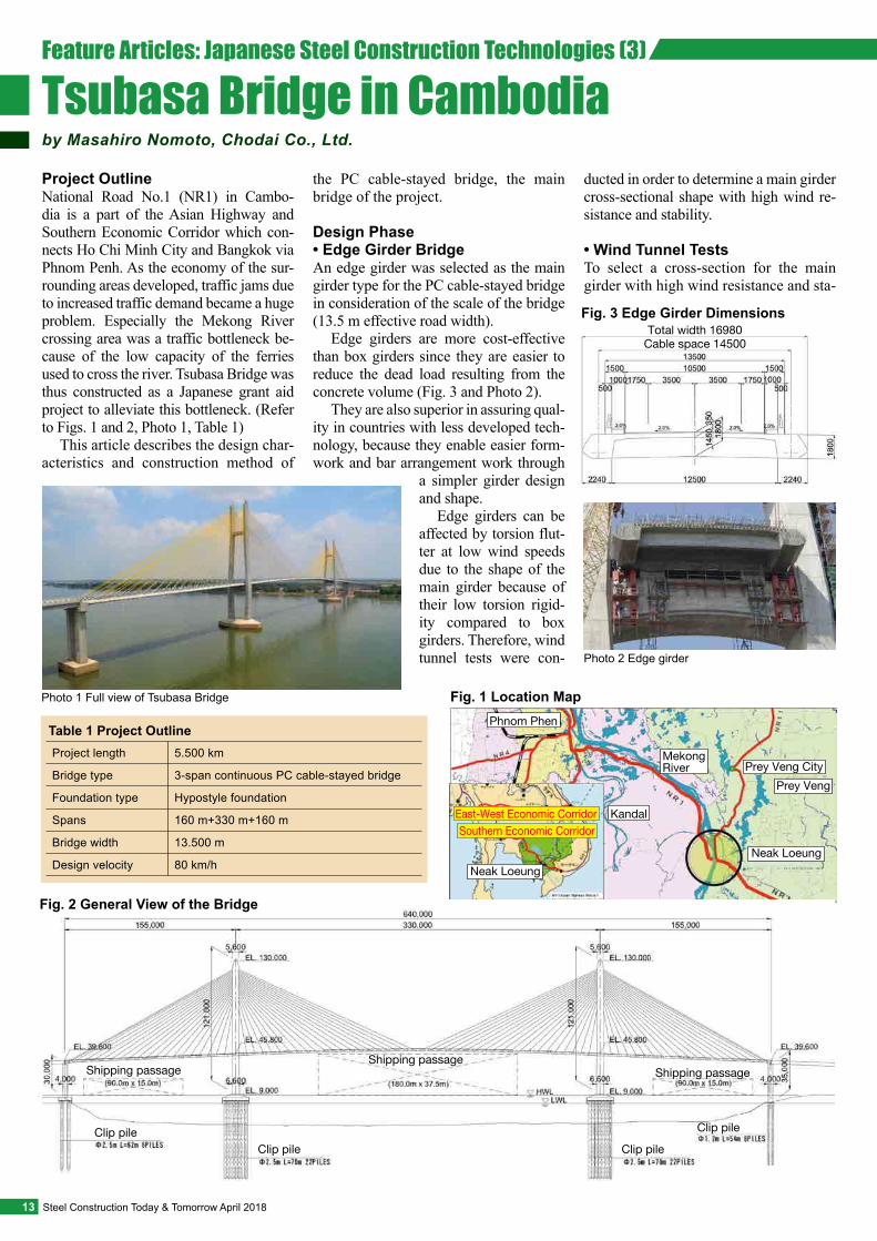
Project OutlineNational Road No.1 (NR1) in Cambo-dia is a part of the Asian Highway and Southern Economic Corridor which con-nects Ho Chi Minh City and Bangkok via Phnom Penh. As the economy of the sur-rounding areas developed, traffic jams due to increased traffic demand became a huge problem. Especially the Mekong River crossing area was a traffic bottleneck be-cause of the low capacity of the ferries used to cross the river. Tsubasa Bridge was thus constructed as a Japanese grant aid project to alleviate this bottleneck. (Refer to Figs. 1 and 2, Photo 1, Table 1)
This article describes the design char-acteristics and construction method of
the PC cable-stayed bridge, the main bridge of the project.
Design Phase• Edge Girder BridgeAn edge girder was selected as the main girder type for the PC cable-stayed bridge in consideration of the scale of the bridge (13.5 m effective road width).
Edge girders are more cost-effective than box girders since they are easier to reduce the dead load resulting from the concrete volume (Fig. 3 and Photo 2).
They are also superior in assuring qual-ity in countries with less developed tech-nology, because they enable easier form-work and bar arrangement work through
a simpler girder design and shape.
Edge girders can be affected by torsion flut-ter at low wind speeds due to the shape of the main girder because of their low torsion rigid-ity compared to box girders. Therefore, wind tunnel tests were con-
ducted in order to determine a main girder cross-sectional shape with high wind re-sistance and stability.
• Wind Tunnel TestsTo select a cross-section for the main girder with high wind resistance and sta-
Fig. 1 Location Map
Neak Loeung
Southern Economic CorridorEast-West Economic Corridor
Phnom Phen
Kandal
MekongRiver Prey Veng City
Prey Veng
Neak Loeung
Shipping passageShipping passageShipping passage
Clip pile Clip pileClip pile Clip pile
Fig. 2 General View of the Bridge
Table 1 Project Outline
Foundation type
Spans
Bridge width
Design velocity
Bridge type
Project length
Hypostyle foundation
160 m+330 m+160 m
13.500 m
80 km/h
3-span continuous PC cable-stayed bridge
5.500 km
Total width 16980Cable space 14500
Fig. 3 Edge Girder Dimensions
13 Steel Construction Today & Tomorrow April 2018
Photo 1 Full view of Tsubasa Bridge
Photo 2 Edge girder
Feature Articles: Japanese Steel Construction Technologies (3)
Tsubasa Bridge in Cambodiaby Masahiro Nomoto, Chodai Co., Ltd.
Original cross section
Fairing—Upper 30 degrees
Fairing (small)Fairing (large)
Fig. 4 Fairings for Wind Tunnel Testing
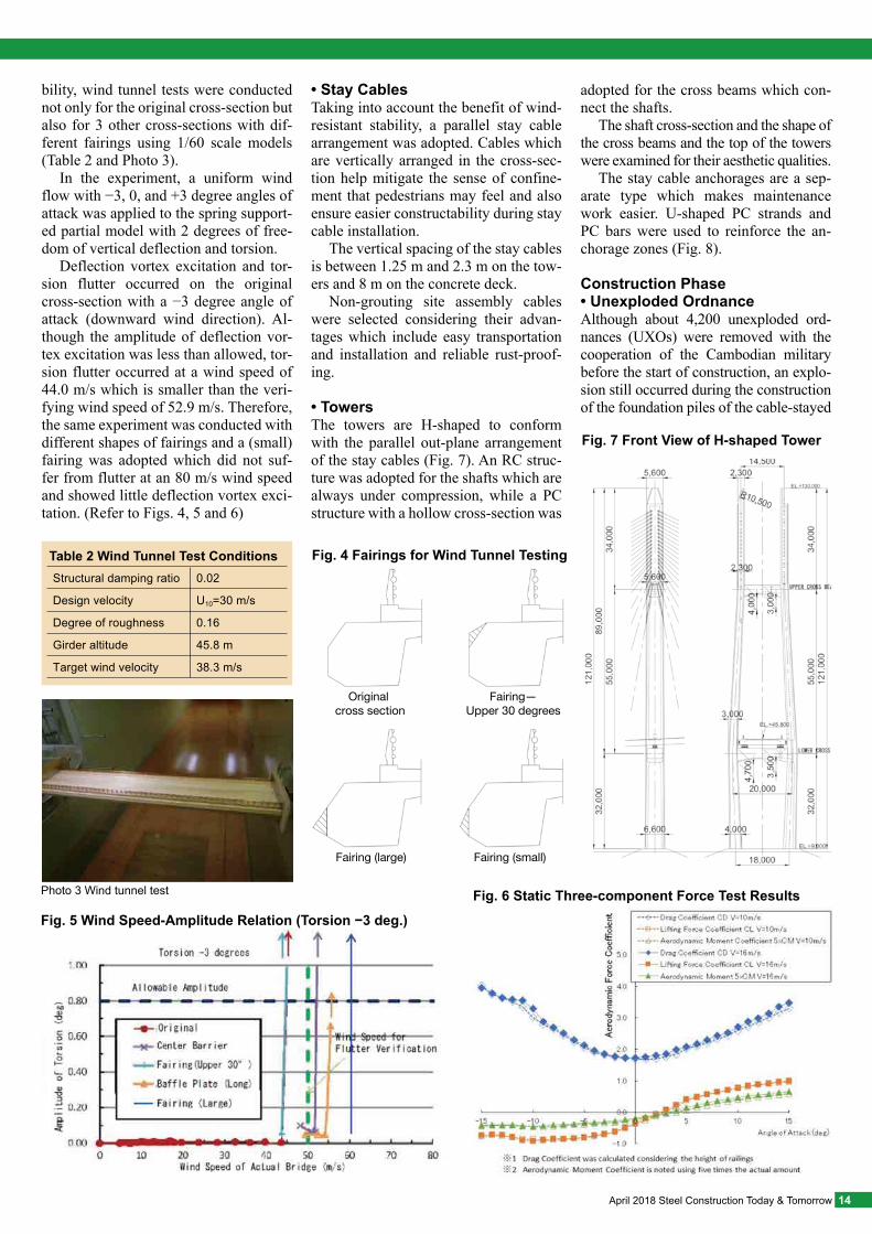
bility, wind tunnel tests were conducted not only for the original cross-section but also for 3 other cross-sections with dif-ferent fairings using 1/60 scale models (Table 2 and Photo 3).
In the experiment, a uniform wind flow with −3, 0, and +3 degree angles of attack was applied to the spring support-ed partial model with 2 degrees of free-dom of vertical deflection and torsion.
Deflection vortex excitation and tor-sion flutter occurred on the original cross-section with a −3 degree angle of attack (downward wind direction). Al-though the amplitude of deflection vor-tex excitation was less than allowed, tor-sion flutter occurred at a wind speed of 44.0 m/s which is smaller than the veri-fying wind speed of 52.9 m/s. Therefore, the same experiment was conducted with different shapes of fairings and a (small) fairing was adopted which did not suf-fer from flutter at an 80 m/s wind speed and showed little deflection vortex exci-tation. (Refer to Figs. 4, 5 and 6)
• Stay CablesTaking into account the benefit of wind-resistant stability, a parallel stay cable arrangement was adopted. Cables which are vertically arranged in the cross-sec-tion help mitigate the sense of confine-ment that pedestrians may feel and also ensure easier constructability during stay cable installation.
The vertical spacing of the stay cables is between 1.25 m and 2.3 m on the tow-ers and 8 m on the concrete deck.
Non-grouting site assembly cables were selected considering their advan-tages which include easy transportation and installation and reliable rust-proof-ing.
• TowersThe towers are H-shaped to conform with the parallel out-plane arrangement of the stay cables (Fig. 7). An RC struc-ture was adopted for the shafts which are always under compression, while a PC structure with a hollow cross-section was
adopted for the cross beams which con-nect the shafts.
The shaft cross-section and the shape of the cross beams and the top of the towers were examined for their aesthetic qualities.
The stay cable anchorages are a sep-arate type which makes maintenance work easier. U-shaped PC strands and PC bars were used to reinforce the an-chorage zones (Fig. 8).
Construction Phase• Unexploded OrdnanceAlthough about 4,200 unexploded ord-nances (UXOs) were removed with the cooperation of the Cambodian military before the start of construction, an explo-sion still occurred during the construction of the foundation piles of the cable-stayed
Table 2 Wind Tunnel Test Conditions
Degree of roughness
Girder altitude
Target wind velocity
Design velocity
Structural damping ratio
0.16
45.8 m
38.3 m/s
U10=30 m/s
0.02
Fig. 5 Wind Speed-Amplitude Relation (Torsion −3 deg.)
Fig. 6 Static Three-component Force Test Results
Fig. 7 Front View of H-shaped Tower
14April 2018 Steel Construction Today & Tomorrow
Photo 3 Wind tunnel test
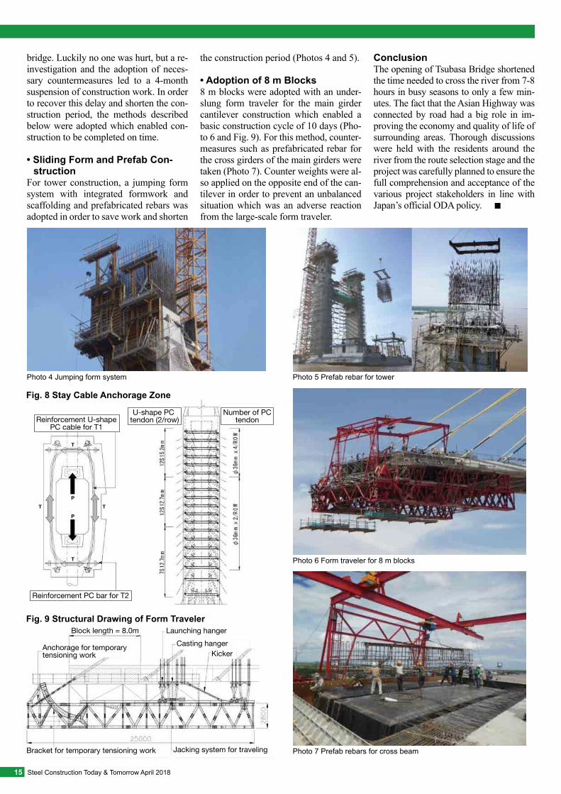
bridge. Luckily no one was hurt, but a re-investigation and the adoption of neces-sary countermeasures led to a 4-month suspension of construction work. In order to recover this delay and shorten the con-struction period, the methods described below were adopted which enabled con-struction to be completed on time.
• Sliding Form and Prefab Con-struction
For tower construction, a jumping form system with integrated formwork and scaffolding and prefabricated rebars was adopted in order to save work and shorten
the construction period (Photos 4 and 5).
• Adoption of 8 m Blocks8 m blocks were adopted with an under-slung form traveler for the main girder cantilever construction which enabled a basic construction cycle of 10 days (Pho-to 6 and Fig. 9). For this method, counter-measures such as prefabricated rebar for the cross girders of the main girders were taken (Photo 7). Counter weights were al-so applied on the opposite end of the can-tilever in order to prevent an unbalanced situation which was an adverse reaction from the large-scale form traveler.
ConclusionThe opening of Tsubasa Bridge shortened the time needed to cross the river from 7-8 hours in busy seasons to only a few min-utes. The fact that the Asian Highway was connected by road had a big role in im-proving the economy and quality of life of surrounding areas. Thorough discussions were held with the residents around the river from the route selection stage and the project was carefully planned to ensure the full comprehension and acceptance of the various project stakeholders in line with Japan’s official ODA policy. ■
15 Steel Construction Today & Tomorrow April 2018
Photo 4 Jumping form system
Photo 6 Form traveler for 8 m blocks
Photo 5 Prefab rebar for tower
Photo 7 Prefab rebars for cross beam
P
P
T
T
TT
Fig. 8 Stay Cable Anchorage Zone
Number of PCtendon
U-shape PC tendon (2/row)Reinforcement U-shape
PC cable for T1
Reinforcement PC bar for T2
Jacking system for travelingBracket for temporary tensioning work
Anchorage for temporary tensioning work
Block length = 8.0m Launching hangerCasting hanger
Kicker
Fig. 9 Structural Drawing of Form Traveler
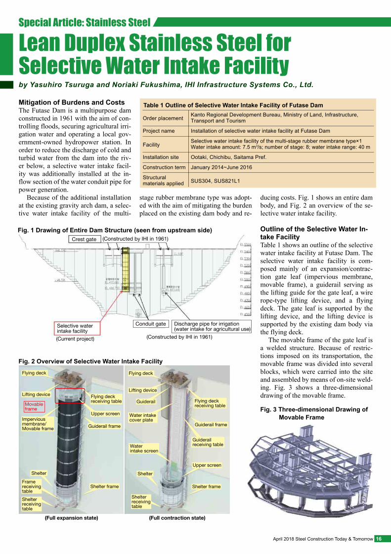
Mitigation of Burdens and CostsThe Futase Dam is a multipurpose dam constructed in 1961 with the aim of con-trolling floods, securing agricultural irri-gation water and operating a local gov-ernment-owned hydropower station. In order to reduce the discharge of cold and turbid water from the dam into the riv-er below, a selective water intake facil-ity was additionally installed at the in-flow section of the water conduit pipe for power generation.
Because of the additional installation at the existing gravity arch dam, a selec-tive water intake facility of the multi-
stage rubber membrane type was adopt-ed with the aim of mitigating the burden placed on the existing dam body and re-
ducing costs. Fig. 1 shows an entire dam body, and Fig. 2 an overview of the se-lective water intake facility.
Outline of the Selective Water In-take Facility Table 1 shows an outline of the selective water intake facility at Futase Dam. The selective water intake facility is com-posed mainly of an expansion/contrac-tion gate leaf (impervious membrane, movable frame), a guiderail serving as the lifting guide for the gate leaf, a wire rope-type lifting device, and a flying deck. The gate leaf is supported by the lifting device, and the lifting device is supported by the existing dam body via the flying deck.
The movable frame of the gate leaf is a welded structure. Because of restric-tions imposed on its transportation, the movable frame was divided into several blocks, which were carried into the site and assembled by means of on-site weld-ing. Fig. 3 shows a three-dimensional drawing of the movable frame.
16April 2018 Steel Construction Today & Tomorrow
Table 1 Outline of Selective Water Intake Facility of Futase Dam
Order placement Kanto Regional Development Bureau, Ministry of Land, Infrastructure, Transport and Tourism
FacilitySelective water intake facility of the multi-stage rubber membrane type×1Water intake amount: 7.5 m3/s; number of stage: 8; water intake range: 40 m
Installation site Ootaki, Chichibu, Saitama Pref.
Construction term January 2014~June 2016
Structural materials applied SUS304, SUS821L1
Project name Installation of selective water intake facility at Futase Dam
Selective water intake facility
Conduit gate Discharge pipe for irrigation (water intake for agricultural use)
(Constructed by IHI in 1961)(Current project)
Crest gate (Constructed by IHI in 1961)Fig. 1 Drawing of Entire Dam Structure (seen from upstream side)
Shelter receiving table
Shelter receiving table
(Full expansion state) (Full contraction state)
Frame receiving table
Shelter
Impervious membrane/Movable frame
Movableframe
Lifting device
Flying deck
Flying deck receiving table
Upper screen
Guiderail frame
Shelter frame
Flying deck
Lifting device
Guiderail
Water intake cover plate
Water intake screen
Shelter
Flying deck receiving table
Guiderail frame
Guiderail receiving table
Upper screen
Shelter frame
Fig. 2 Overview of Selective Water Intake Facility
Fig. 3 Three-dimensional Drawing of Movable Frame
Special Article: Stainless Steel
Lean Duplex Stainless Steel for Selective Water Intake Facilityby Yasuhiro Tsuruga and Noriaki Fukushima, IHI Infrastructure Systems Co., Ltd.
Features of Lean Duplex Stainless SteelThe application of duplex stainless is growing worldwide. In order to incor-porate the attainments obtained in the development of the new duplex stain-less steel, lean duplex stainless steel was standardized in the Japanese Industrial Standards in 2015. Currently two steel grades, SUS821L1 and SUS323L, are registered as lean duplex stainless steel in the Standards.
In comparison with the conventional duplex stainless steel SUS329J4L, lean duplex stainless steel is manufactured by suppressing the addition of the expensive elements Ni and Mo and adding N to the extent that it does not affect weldabili-ty. The end result thus attained for lean duplex stainless steel is the realization of high strength, which is about twice that of SUS304, and economic advantages, corrosion resistance and weldability sim-ilar to those of SUS304. Table 2 shows the main composition and mechanical properties of lean duplex stainless steel.
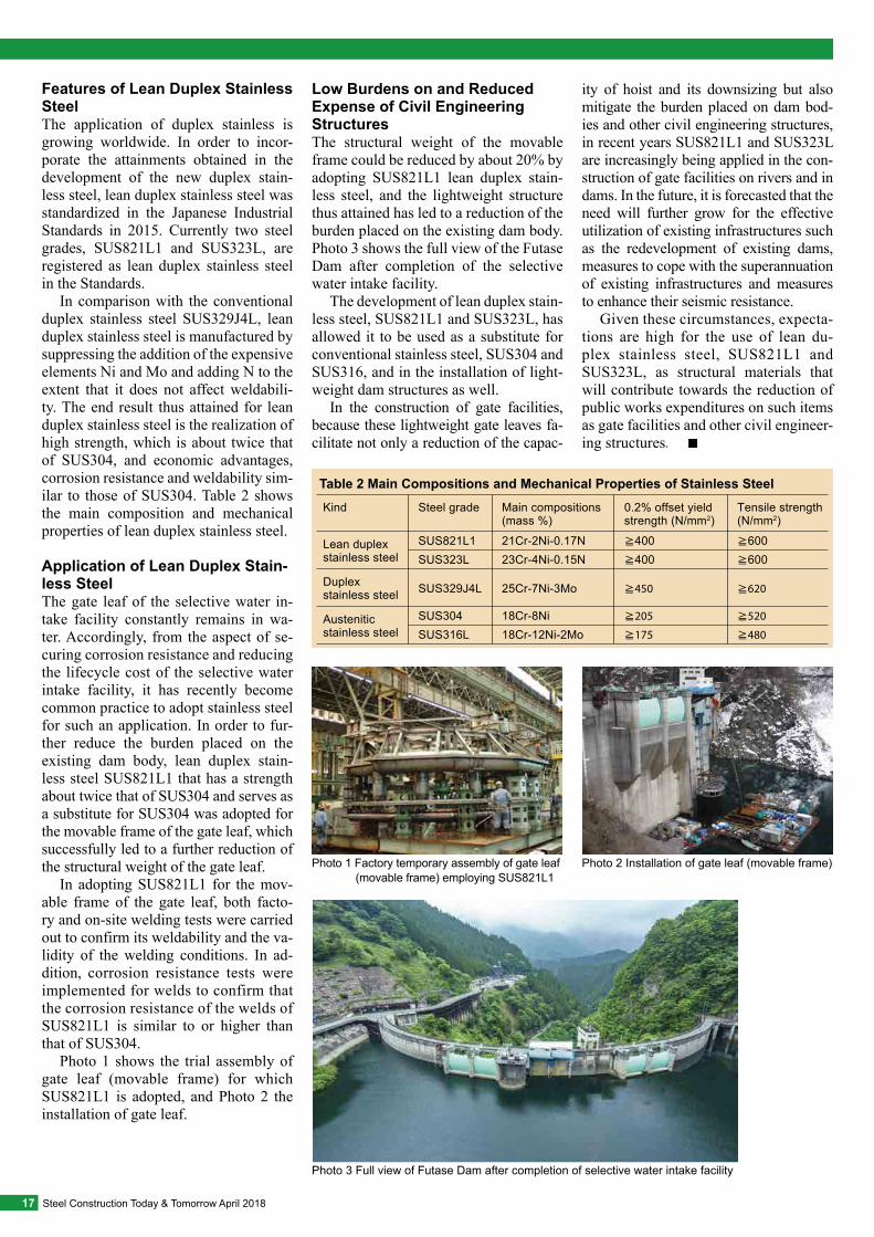
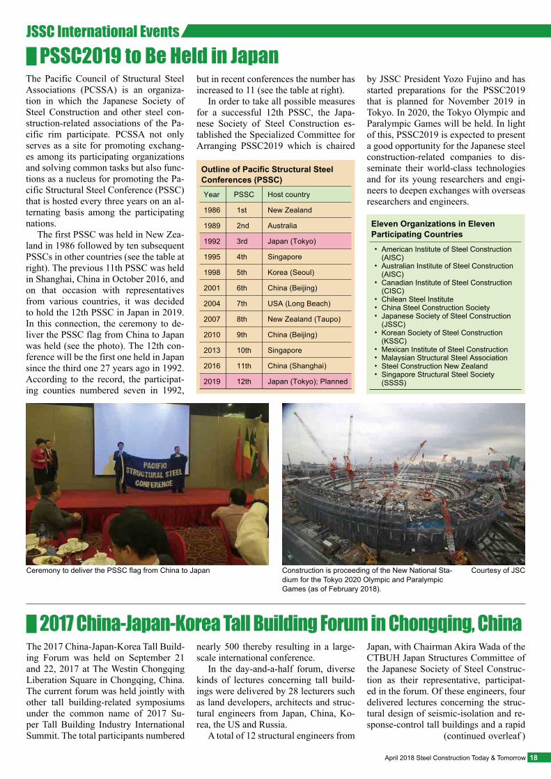
Application of Lean Duplex Stain-less SteelThe gate leaf of the selective water in-take facility constantly remains in wa-ter. Accordingly, from the aspect of se-curing corrosion resistance and reducing the lifecycle cost of the selective water intake facility, it has recently become common practice to adopt stainless steel for such an application. In order to fur-ther reduce the burden placed on the existing dam body, lean duplex stain-less steel SUS821L1 that has a strength about twice that of SUS304 and serves as a substitute for SUS304 was adopted for the movable frame of the gate leaf, which successfully led to a further reduction of the structural weight of the gate leaf.
In adopting SUS821L1 for the mov-able frame of the gate leaf, both facto-ry and on-site welding tests were carried out to confirm its weldability and the va-lidity of the welding conditions. In ad-dition, corrosion resistance tests were implemented for welds to confirm that the corrosion resistance of the welds of SUS821L1 is similar to or higher than that of SUS304.
Photo 1 shows the trial assembly of gate leaf (movable frame) for which SUS821L1 is adopted, and Photo 2 the installation of gate leaf.
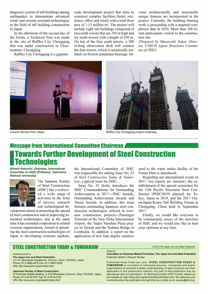
Low Burdens on and Reduced Expense of Civil Engineering StructuresThe structural weight of the movable frame could be reduced by about 20% by adopting SUS821L1 lean duplex stain-less steel, and the lightweight structure thus attained has led to a reduction of the burden placed on the existing dam body. Photo 3 shows the full view of the Futase Dam after completion of the selective water intake facility.
The development of lean duplex stain-less steel, SUS821L1 and SUS323L, has allowed it to be used as a substitute for conventional stainless steel, SUS304 and SUS316, and in the installation of light-weight dam structures as well.
In the construction of gate facilities, because these lightweight gate leaves fa-cilitate not only a reduction of the capac-
ity of hoist and its downsizing but also mitigate the burden placed on dam bod-ies and other civil engineering structures, in recent years SUS821L1 and SUS323L are increasingly being applied in the con-struction of gate facilities on rivers and in dams. In the future, it is forecasted that the need will further grow for the effective utilization of existing infrastructures such as the redevelopment of existing dams, measures to cope with the superannuation of existing infrastructures and measures to enhance their seismic resistance.
Given these circumstances, expecta-tions are high for the use of lean du-plex stainless steel, SUS821L1 and SUS323L, as structural materials that will contribute towards the reduction of public works expenditures on such items as gate facilities and other civil engineer-ing structures. ■
17 Steel Construction Today & Tomorrow April 2018
Photo 3 Full view of Futase Dam after completion of selective water intake facility
Photo 2 Installation of gate leaf (movable frame)Photo 1 Factory temporary assembly of gate leaf (movable frame) employing SUS821L1
Table 2 Main Compositions and Mechanical Properties of Stainless Steel
Lean duplexstainless steel
Kind
Duplex stainless steel
Austenitic stainless steel
Steel grade
SUS821L1SUS323L
SUS329J4L
SUS304SUS316L
Main compositions (mass %)
21Cr-2Ni-0.17N23Cr-4Ni-0.15N
25Cr-7Ni-3Mo
18Cr-8Ni18Cr-12Ni-2Mo
0.2% offset yield strength (N/mm2)
≧400
≧400
≧450
≧205
≧175
≧600
≧600
≧620
≧520
≧480
Tensile strength (N/mm2)
Ceremony to deliver the PSSC flag from China to Japan Construction is proceeding of the New National Sta-dium for the Tokyo 2020 Olympic and Paralympic Games (as of February 2018).
Courtesy of JSC
2017 China-Japan-Korea Tall Building Forum in Chongqing, China
The Pacific Council of Structural Steel Associations (PCSSA) is an organiza-tion in which the Japanese Society of Steel Construction and other steel con-struction-related associations of the Pa-cific rim participate. PCSSA not only serves as a site for promoting exchang-es among its participating organizations and solving common tasks but also func-tions as a nucleus for promoting the Pa-cific Structural Steel Conference (PSSC) that is hosted every three years on an al-ternating basis among the participating nations.
The first PSSC was held in New Zea-land in 1986 followed by ten subsequent PSSCs in other countries (see the table at right). The previous 11th PSSC was held in Shanghai, China in October 2016, and on that occasion with representatives from various countries, it was decided to hold the 12th PSSC in Japan in 2019. In this connection, the ceremony to de-liver the PSSC flag from China to Japan was held (see the photo). The 12th con-ference will be the first one held in Japan since the third one 27 years ago in 1992. According to the record, the participat-ing counties numbered seven in 1992,
The 2017 China-Japan-Korea Tall Build-ing Forum was held on September 21 and 22, 2017 at The Westin Chongqing Liberation Square in Chongqing, China. The current forum was held jointly with other tall building-related symposiums under the common name of 2017 Su-per Tall Building Industry International Summit. The total participants numbered
but in recent conferences the number has increased to 11 (see the table at right).
In order to take all possible measures for a successful 12th PSSC, the Japa-nese Society of Steel Construction es-tablished the Specialized Committee for Arranging PSSC2019 which is chaired
nearly 500 thereby resulting in a large-scale international conference.
In the day-and-a-half forum, diverse kinds of lectures concerning tall build-ings were delivered by 28 lecturers such as land developers, architects and struc-tural engineers from Japan, China, Ko-rea, the US and Russia.
A total of 12 structural engineers from
by JSSC President Yozo Fujino and has started preparations for the PSSC2019 that is planned for November 2019 in Tokyo. In 2020, the Tokyo Olympic and Paralympic Games will be held. In light of this, PSSC2019 is expected to present a good opportunity for the Japanese steel construction-related companies to dis-seminate their world-class technologies and for its young researchers and engi-neers to deepen exchanges with overseas researchers and engineers.
Japan, with Chairman Akira Wada of the CTBUH Japan Structures Committee of the Japanese Society of Steel Construc-tion as their representative, participat-ed in the forum. Of these engineers, four delivered lectures concerning the struc-tural design of seismic-isolation and re-sponse-control tall buildings and a rapid
(continued overleaf )
Outline of Pacific Structural Steel Conferences (PSSC)Year
1986
1989
1992
1995
1998
2001
2004
2007
2010
2013
2016
2019
PSSC
1st
2nd
3rd
4th
5th
6th
7th
8th
9th
10th
11th
12th
Host country
New Zealand
Australia
Japan (Tokyo)
Singapore
Korea (Seoul)
China (Beijing)
USA (Long Beach)
New Zealand (Taupo)
China (Beijing)
Singapore
China (Shanghai)
Japan (Tokyo); Planned
Eleven Organizations in Eleven Participating Countries•
•
•
•••
•
••••
American Institute of Steel Construction (AISC)Australian Institute of Steel Construction (AISC)Canadian Institute of Steel Construction (CISC)Chilean Steel InstituteChina Steel Construction SocietyJapanese Society of Steel Construction (JSSC)Korean Society of Steel Construction (KSSC)Mexican Institute of Steel ConstructionMalaysian Structural Steel AssociationSteel Construction New ZealandSingapore Structural Steel Society (SSSS)
18April 2018 Steel Construction Today & Tomorrow
JSSC International EventsPSSC2019 to Be Held in Japan
diagnosis system of tall buildings during earthquakes to demonstrate advanced wind- and seismic-resistant technologies in the field of tall building construction in Japan.
In the afternoon of the second day of the forum, a Technical Tour was made to the site of Raffles City Chongqing that was under construction in Chao-tianmen, Chongqing.
Raffles City Chongqing is a gigantic-
STEEL CONSTRUCTION TODAY & TOMORROWCommittee on Overseas Market Promotion, The Japan Iron and Steel FederationChairman (Editor): Hiroyuki Tanaka
Edited by
Publ ished three t imes per year, STEEL CONSTRUCTION TODAY & TOMORROW is circulated to interested persons, companies and public organizations to promote a better understanding of steel products and their application in the construction industry. Any part of this publication may be reproduced with our permission. To download content (PDF format), please go our website at: http://www.jisf.or.jp/en/activitity/sctt/index.html. We welcome your comments about the publication and ask that you contact us at: [email protected].
© 2018 The Japan Iron and Steel Federation
Japanese Society of Steel Construction3F Aminosan Kaikan Building, 3-15-8 Nihonbashi, Chuo-ku, Tokyo 103-0027, JapanPhone: 81-3-3516-2151 Fax: 81-3-3516-2152URL http://www.jssc.or.jp/english/index.html
The Japan Iron and Steel Federation3-2-10, Nihonbashi Kayabacho, Chuo-ku, Tokyo 103-0025, JapanPhone: 81-3-3669-4815 Fax: 81-3-3667-0245URL http://www.jisf.or.jp/en/index.html
Published jointly by
scale development project that aims to construct complex facilities (hotel, resi-dence, office and retail) with a total floor area of 1.13 million m2. The project will include eight tall buildings composed of two north towers that are 350 m high and six south towers with a height of 250 m. On top of the four south towers, a 300 m-long observation deck will connect the four towers, which is seismically iso-lated via friction pendulum bearings. Di-
verse architecturally and structurally unique features are incorporated in the project. Currently, the building framing work is proceeding with a targeted com-pletion date in 2019. More than 100 fo-rum participants visited to the construc-tion site.(Prepared by Masayoshi Nakai, Direc-tor, CTBUH Japan Structures Commit-tee of JSSC)
Towards Further Development of Steel Construction Technologies
The Japanese Society of Steel Construction (JSSC) has conduct-ed a wide range of activities in the form of surveys, research and technological de-
velopment aimed at promoting the spread of steel construction and at improving as-sociated technologies, and at the same time it has extended cooperation to related overseas organizations. Aimed at spread-ing the steel construction technologies of Japan to developing overseas markets,
the International Committee of JSSC was responsible for editing Issue No. 53 of Steel Construction Today & Tomor-row, a special issue for JSSC.
Issue No. 53 firstly introduces the JSSC Commendations for Outstanding Achievements in 2017-JSSC Awards, Outstanding Achievement Awards and Thesis Awards. In addition, this issue features outstanding Japanese steel con-struction technologies utilized in over-seas construction projects-Passenger Terminal of the New Doha International Airport, the Taipei Nanshan Plaza proj-ect in Taiwan and the Tsubasa Bridge in Cambodia. In addition, a report on the application of new lean duplex stainless
steel to the water intake facility of the Futase Dam is introduced.
Regarding our international events in 2017, two reports are inserted-the es-tablishment of the special committee for the 12th Pacific Structural Steel Con-ference (PSSC2019) planned for To-kyo, Japan in 2019, and the 2017 Chi-na-Japan-Korea Tall Building Forum in Chongqing, China held in September 2017.
Finally, we would like everyone to be continuously aware of the activities of JSSC and we would also like to hear your opinions at any time.
Hiroshi Katsuchi, Chairman, International Committee of JSSC (Professor, Yokohama National University)
Lecture delivery from Japan Raffles City Chongqing project underway
Message from International Committee Chairman