Embed Size (px)
Citation preview
.
wesr�rn Electric
NO. 23A
RADIO TRANSMITTER -
.
PRELI};IINA.RY INSTRUCTIONS
843-P
WESTERN ELEJ TRIC
NO. 23A RADIO TRANEMITTER
PRELIMINARY l.'NSTWCTIONS
No. 843P
WESTEim �TRIC COM!>ANY
./-. -
WESTERN ELPX:TRIC
NO. 23A :RADIO TRANS1vll'l'TER
GmERAL DESCRIPj'ION
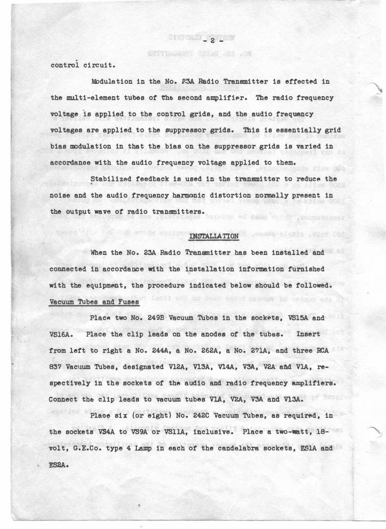
The lie stern Electric No. 23A Radio Tranemi tter will deliver a
DllXitmJ.m of 250 watts of completely modulated radio fr�quency carrier power
at any frequency between 550 and 1€00 kc. Normally it operates from a 200-
240 volt single-phase, 50-60 cycle, powBr source, requiring approximat�ly
2300 watts at a 90% power factor for 250-watt operation and approxin&tely
1900 watts at a 90%, power factor tor 100 watt operation. An auto-
transformer, which ll1lSt be ordered sepe.ratf9ly, can be supplied for 100-
120 volt, single-phase, 50-60 cycle operation where 200-240 volt power
is not available.
The No. 310A and No. 310B Radio Transmitting Equipments each
consist of a fully equipped No. 23A Radio Transmitter and differ only . .
in the number Of vacuum tubes us�d in the final radio frequency ampli-
fier. The No. 310A Radio Transmitting Equipment uses tour vacuum tubes
for 100-watt service and the No. 310B Radio Transmitting Equipment uses
six vacuum tubes in the final amplifier for 100/250 watt service.
The No. 23A Radio Transmitter consists ot a quartz-controlled
oscillator, a butter amplifier, a balanced modulating amplifier fol-
lowed by two radio-frequency balanced linear amplifiers, two stages of
audio-frequency amplification, a feedback rectifier and a plate voltage
rectifier with associated tilter and control circuits. A flashing
signal lamp indicates the proper operation of the oscillator temperature-
- 2 -
.
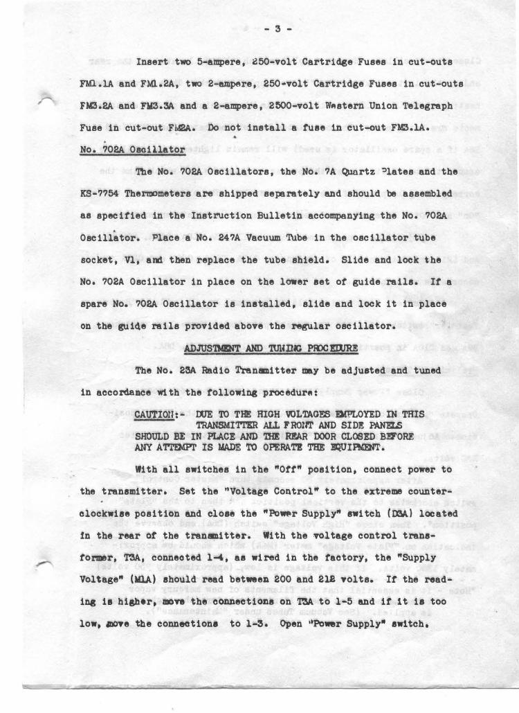
control circuit.
M:>dulation in the No. ?.3A Radio Transmitter is ettect�d in
the multi-element tubes ot t'h6 second amplifiPr. The radio trequency
voltage is applied to the control grids, and the audio trequency
voltages are applied to t he suppressor grids. This is essentially grid
bias modulation in that the bias on the suppressor grids is varied in
accordanoe with the audio frequency voltage applied to them.
Stabilized feedback is used in the transmitter to reduce the .
noise and the audio frequency harmonic distortion normally present in
the output wave ot radio transmitters.
IN&'TALIATION
When the No. 23A Radio Trananitter has been installed and
connected in accordance with the installation intormation furnished
with the equipm�t, the procedure indicated below should be followed.
Vacuum Tubes and Fuses
Plac111 two No. 249B Vacuum Tubes in the sockets, VS15A and
VS16A. Place the clip leads on the anodes ot the tubes. Insert
trom lett to right a No. 244A, a No. 262A, a No. 271A, and three RCA
837 Vacuum Tubes, designated Vl2A, Vl3A, Vl4A, V3A, V2A a1ld VlA, re-
spectively in th e sockets or th� audio and radio frequency amplitiers.
Connect the clip leads to vacuum tubes VlA, V2A, V3A and Vl.3A.
Plaoe six (or eight) No. 242C Vacuum Tubes, as requirt1d, in
the sockets VS4A to VS9A or VSllA, inclusive. Place a two-watt, 18-
volt, G.E.Co. type 4 Lamp in each of the candelabra sockets, ESlA and
�.
- 3 -
Insert two 5-ampere, 250-volt Cartrid8e Fuses in cut-outs
no..lA and FMl.2A, two 2-empere, 250 .. volt Cartridge Fuses in cut-outs
FM3.2A and nt3.3A and a 2-ampere, 2500-volt W11tstern Union Telegraph
Fuse in cut-out FMP.A. Do not install a tuse 1n cut-out FM3.1A •
. No. 702A Osoillator
The No. 702A Oscillators, the No. 7A Quartz Plates and the
KS-7754 Therroometers are shipped separately and should be assembled
as specified in the Instruction Bulletin accompanying the No. 702A .
Oscillator. Place a No. 247A Vacuum 'l\.lbe in the oscillator tube
socket, Vl, and then replace the tube shield. Slide and lock the
No. 702A Oscillator in place on the lower set of guide rails. It a
spare No. 702A Oscillator is installed, slide and lock it in place
on the gui4e rails provided above the resular oscillator.
ADJUS'IMINT AND '!UHDJG Pll>CEilJRE
The No. 23A Radio Tranmitter may be adjusted and tuned
in accordance w1 th the following procedure:
CAUTION:- OOE TO THE HIGH VOLTAGES l!MPLOYED IN THIS TRANSMITTBR ALL 1'ROllI' AND SIDE PANELS
SHOULD BE IN PLACE AND 'ml R!AR DOOR CL�ED Bl!J'ORE ANY A'l"l"!MPr IS MADE TO OPERA'l'! THE JJQUIFMmT.
With all switches in the "Ott" position, connect po\lrer to
the transmitter. Set the "Voltage Control" to the �xtreme counter-
clockwise position and close the "Powr SUpply" ni tcb {OOA) located
:fn the rear � the tranmitter. With the wltage control trans-
fo:nner, T3A., connected 1-l, as wired in the factory, the "Supply
Vol\age" (Ml.A) should read between 200 and 218 volts. It the read-
ing ia higher, mon the connections on T3A to l-5 and it 1 t is too
low, aove the conneotione to 1-3. Open 1'Po•r Supply" awttch.
- 4 -
Close the "Oscillator Heater Supply" switch, (DlA), located in the rear
and to the lett and above the "l?ower Supply" switeh. This permits the .
heating ot the No. 702A Oscillator wh11� the reI111inder ot the adjust-
ments are being nede. 'lbe oscillator heater indicator lamp ElA (an4
E2A if a spare osc.illator is used) will remin lighted only until the
associated oscillator is at the proper temperature, at which time the
corresponding lamp will tlash intermittently. The exact time ot the
"On" and·0of't" intervals is dependent upon the ambient temperature.
Adjust the taps on inductance coils L3A, LSA, LUA, Ll8.1A
and L2lA and set controls ot condensers CllA, Cl2A, C20A and C2lA in
accordance with Table I.
Connect link switch DllA to terminal No. 21. Place ''Power
Transfer" switch (Dl2A) in the "High" position. Place link switches
D9A and DlOA in position No. l, and close link switch� DSA.
Preliminary 'l\lning
Close "Powe:r Supply" swt tch and close the rear door.
Operate "Master Control" &Witch (D4A) clockwise to the "Fil." posi-
tion. Adjust "Voltage Control" until "Supply Voltages" indicates
220 volts.
After approximately 30 seconds turn "Master Control"
switch clockwise to the vertical position and then to the "Plate"
position*. Then close "High Voltage" swttch (D5A) and observe tht>
indication on "Plate Voltage" meter (M4A) which should b8 approxi
nately 1300 volts. It this voltage is low, (approximately 750 volts) - - - - - - - - - - - - - - - - - - - - - - - -
�ote - It is essential that the tilaments ot new mercury vapor tubes be heated at least 15 minutes before the high voltage is applied. (See Vacuum Tubes under "?.Bintenance").
- 5 -
check operation of relay �A in accordance with the information given
under "Location ot Trouble". In the following tuning procedure the
controls are adjueted With a ape.nner wrench furnished with.the equip
ment. Place "Test Meter Switch'' (D7A} in each of· the eight positions,
and note that in no caae is the "Test Meter:• (M2A) ott scale.
Set ''Teat Meter Switch" in position "lst R.F. Amp. Plate•
and adjust "let Amp. Tuning" control (t4A and CM) until "Teat Current''
meter reads a minimum. Change "Test i.feter Switch" to "2nd R.F. Amp.
Grid'' and readjust "lat Amp. Tuning" slightly tor a mximum on "Test
Current" meter.
Adjust "let Amp. Output" control (R8A.} until "Test Current"
meter reads approximtely midway between the limits given in Table II.
Set "Test Heter Switch" to "2nd R.F. Amp. ?late" and adjust "2nd Amp.
Tuning" control (Cl3A) until "Test Current" meter reads a miniDl.llll.
Change "Test Meter Switch" to "3rd R.F. Anq>. Plate'' and adjuet "3rd
Amp. Tuning" control (CW.) until "4th Amp. �late Current" reads a
DllxiDlml. Check "2nd R.F. Grid" and "3rd R.F. Amp. Pl;ate" currents
With Table II.
Set "4th Amp. Coupling" control at zero and ''4th Amp.
Input" oontrol (R20A) to approximately mid-position. Adjust
"4th Amp. '1\ming" control (C32A) until "�th Amp. Output Current"
meter (Ll>A) reads a 111BXimum. Thia is obtained by alternately
adjusting "4th .Amp. Input" control and "4th Amp. 'l'uning" control
r" until "4th Amp. Output Current" reads a DBximm at approxinately
l.O ampere. The "Transmission Line Current" meter (�A) should
read zero.
- 6 -
NEUTHALIZDlG
The third and fourth amplitiers must now be neutralized in
the following manner: Shut down the transmitter and disconnect the
thermocouple end ot the lead between C34A and 'rolA. With a temporary
jumper connect the tree end ot this lead to the clip on. UlA. Set
the teat meter switch to the "Feedback Rec" position. Open Link Switches
D9A and DlOA. Start the transmitter and increase the "4th Amp. Coupling"
a slight amount. Adjust the "Coupling Circuit 'l\aning" control (L21A)
tor a zmximum indicati:>n ot the "Test Meter". Full scale reading of the
"Teat Meter" should not be exceeded during this proc�ss, a reduction in
the setting ot "4th Amp. Input" control being mad� it necessary to reduce
the "Teat Meter" �ding to somemat less than tull scale. It in-
suf'ficient reading ot the "T�st Meter• is obtained to g1Te a good in-
dication th� capacity ot C34A should be 1ncreas8d until a satistactol9y
value is obtainflld. Neutralize the fourth amplitier by adjust!� the
"4th Amp. Neutralizing• (C26A) and (C2?A) control for a minimum indica-. .
tion ot the "Test Metfllr". Shut down the transmitter, open link awitch
D6A and close link switches D9A and DlOA to position 1 as before.
Start the transmitter and neutralize the third amplifier by adjusting
the "3rd Amp. Neutralizing" control 1(Cl8A) and (Cl9A) tor a minimum
indication of the "Test Meter•. Shut down the transmitter, close link
switch DBA, remoTe of the temporary jumpfllr, reconnect C34A to 1tlA,
set the "4th Amp. Output Coupling" and C34A to zero.
For transmitters prior to serial #126, a modification ot the
connection chaDges to be made preparatory to neutralizing i• necessary.
In these transmitters the condenser C34A is connected to coil L22A
•
- 7 -
instead of to TClA. Therefore in this case the lead connecting L22A
to C34A should be removed from C34A and connected by means of a
temporary jumper to the point between C35A and C36A. With this change
in connections the neutralizing procedure should be carried out exactly
as previously described.
OUTPUT 'lUNillG
Increase "4th Amp. Coupling" a slight amount and then tune
the coupling circuit by adjusting "Coupling Circuit Tuning" control
until the "4th Amp. Outl)ut Current" meter tndicates a m.inimum.
Then check the tuning of the 4th amplifier for minimum plate current.
Adjust alternately the "4th Amp. Input" control and the
"4th Amp. Coupling" until the "4th Amp. Plate Current" is in accord
with Table II when the "Plate Voltage" is 1250 volts, the "Supply
Voltage" is 220 volts, the "4th Amp. Output Current" is in accordance
with Table II and the "Tra.nsmission Line Current" meter (M6A) indi-
oates the proper output for the power of the tra�smitter as shown in
Table II.
The "4th Amp. ?late Current" meter, is normally connected
to indicate the total plate current in the vacuum tubes ot the final I
amplifier. The plate current indication on this meter ot tubes V6A
and V8A or V6A, V8A and VlOA when D9A is in position 1 and DlOA is
in position 2 should be within 10 ma. of the plate current indication
ot tub�s V?A and V9A or V?A, V9A and VllA when D9A is in position 2
and DlOA is in position 1. This balance can be obtained by adjusting
the relative positions of the contact arms on resistors R20,1A and
R20.2A. The amount that either ot these controls should be moved
depends upon the unbalance indicated on "4th Amp. Plate Current" meter.
\ihen all tilning adjustments are completed, and the transmitter 1•
delivering the desired output power, the meter readings shall be in ac
cordance with Table II, "Typical Meter Reading", with the exception ot
the ''Feedback Rec•'' current which will be adjusted later.
The transm1tt6r is now ready to be connected to the concentric
transmission line by connecting link switch DllA to terminal 20. Thie
line connects the output of the transmitter to the Antenna Coupling
Unit which is adjusted and tuned in accordance with Instruction Bulletin
accompanying it.
Set the teedback rectifier input control until the "Feedback
Rec." current is as indicated in Table II. If aL audio oacillator is
available a more accurate setting ot teedback Il8Y be made as tollows.
With the single frequency audio input level to the transmitter adjusted
to the value of Table II the output tor canplete modulation should be
observed as an increase of 22-1/2� on the "Transmission Line" meter.
If the current increase is either more or less than this increase or
decrease, respectively, C34A until the proper percentage is attained.
This will provide the proper amount ot stabilized teedback. The "Feed
back Rec." current indicated on the "Test Current" meter should be
within the limits given in Table II.
OPERATilJG Pll'>CEDURE
Nol'!IBl Operation ot the 310A or 310B Eq�ipment
When the No. 23A Radio Transmitter is adjusted and tun� as
described in the preceding paragraphs, the routine operation is as
tollows.
The "Oscillator Heater Supply" switch (DlA) ie al•YS l.ett
•On" in order to furnish power to the oso1llator heater o1rcu1 ts.
- 9 -
Before starting the transmitter, the antenna-ground switch
shall be connected to the antenna position, the link switch DllA in
the transmitter shall be connected to terminal No. 20, and the "Power
Transfer" switch shall be either in the "High" position for 250-watt
operation or in the "Low" position for 100-watt operation. The posi
tion of "Power Transfer" switch for 100-Watt operation refers to
either the No. 310A or Uo. 310B Radio Transmitting Equipment.
Note:- l�ever operate the 310A Radio Transmitting Equipment
with the .. Power Transfer·• switch in the "High"
position.
The "Power SUpply" switch is closed, followed by the operation of the
"Mister Control Switch" to the "Fil." position and after a pause of
at least 30 seconds to the "Plate" position. If the "High Voltage"
switch is "On'' the transmitter will deliver power to the antenna.
If the "High Voltage" switch is "Off'', it may be operated at the con
venience of the operator at any time after the "Mister Control
Switch" has been or.,rated to the "Plate'' position. The output power
may be slightly high at first but will be normal as soon as the
equipment has attained the operating temperature.
CAUTION:- In the event of power failure the "High Voltage"
switch, should be operated immediately to the
"01'1''' position. The plate voltage nay be
applied after a 15 second delay following tho
return of the power as indicated by the
"Supply Voltage" meter.
- 10 -
The transmitter is shut down by operating the "�ster Control"
switch clockwise to the �ort" position. Th� transmitter may bA shut
down for a short interval by the "High Voltage" switch. For long shut
down periods operate the "Power Supply" switch to "Oft" in addition to
the "�ster Control" switch.
Modulation and Ili?ni toring
The singlA frequency level of audio power required to completely
modulate the transmitter is given in Table II. For finft quality, the
program level for complete modulation should be 6 db lower than the
single frequency level. Visual monitoring of the carrier may be ac
complished by connecting a cathode ray oscilloscope to terminals
Nos. 12 and 13. A simple anti-resonant circuit across the input of
the oscilloscope mey be used to increase the dAflection.
Monitoring of the transmitter is accomplished by connecting
transmitter terminals Nos. 9 and 10 to the monitoring equipment. ThA
impedance ot this monitoring circuit is 500 ohms and it should be so
terminated.
Reduced Power Qperation for the No. 310B Equipment
In order to reduce the power output from 250 watts to 100
watts the ''?ower Transfer" switch i s operated to the "Low" position.
The "4th Amp . Coupling" and "4th Amp. Input" controls are adjusted
until the proper plate current and transmission line currents are ob
tgined as given in 'Ml�e iAe The audio input lAvel is reduced 5 db
below the lAvel required tor 250 watt operation as indicat�d in
Table II.
- 11 -
General
Cleanliness is essential to the best operation ot this equip-
ment and the unit 1111st be kept tree from dust and dirt. Compressed air or
equivalent is recommended tor cleaning the apparatus inside the en-
closure, but a sott clean cloth may be used with good results. Waste
or oily cloth should never be used.
Care ot Cabinet
The lacquered surfaces and chromium trim may be polished by
rubbing them with a piece of' soft cloth moistened with metal polish
and finally wiping with a dry, clean soft cloth. Any visible grease,
oil or wax should first be reuoved with carbon tetrachloride before
ap�lyinf! the polish.
Air and El.Actrolytic Condensers
The variable air conde�ers in the shield8d compartments I '
should be cleaned at least one� a month with compressed air or
equivalent. This prevents the collection of dust which may result
in the arcing of the condensers thereby taki� the station "of't the
air". C32A shall not be opened as it is sealed against dust.
The �lectrolytic condenser (C29A), associated with the
monitoring c1rcu1 t, bas a lite of' approximately one and one-half
years and should be replaced about once a year. In replacing this
condenser it is essential that the correct polarity be maintained.
Voltage Control Transformer (T3A) The sliding surtace of the voltage control transformer
(�) ehould be cleaned at weekl7 intenale •1th a lintless cloth
•lightly moistened with carbon tetrachloride. In general T3A
- 12 -
should be given the same care as that required by the coD111Utator and brushes
of a motor.
Vacuum Tubes
In order to obtain both IIBximum life and satisfactory per
fornE.nce, it is important that vacuum tubes be opere.ted within their
voltage limits. (See Table II). As far as possible the operator should
anticipate tube failures and IIBke the required tube replacements. Tube
failures DBY be guarded against to some extent by keeping a careful
record of the length of time the tubes have been in service and by
observing from time to time the conditio� of the tube elements.
When the glow of the mercury vapor �ctif ier tubes Vl5A and
Vl6A changes from the normal bluish-green to a very pale blue, the tubes
have reached the end of their useful life and should be replaced.
It is essential that the fila�nte of new mercury vapor
tubes be heated at least 15 minutes bafore the high voltage is applied.
This is in order to remove any particles of mercury adhering to the
sides or elements of the tubes which might result in flashovers.
Spare rectifier tubes should be pre�red for service in advance by
pl.acing them in the equipment when not in use and giving the filaments
the necessary preheating with the "High Voltage" switch (D5A) in the
"Off" position. This procedure should be repeated at least once a month.
Spare rectifier tubes thus preheated should be kept in an upright posi
tion until they are required.
Thermocouples
Whenever damaged external heating elements associated with the
radio frequency meters are sent in for repairs, the heating elements
. �
..
- 13 -
must be accompanied by the associated meter tor calibration purnoses.
Additional Routine
Once a month test all nuts, bolts and screws and tighten any
loose ones. Also, check all connections and it any loose contacts are
found they should be me.de secure. Cases ot trouble can otten be pre
vented by such precaution.
LOOATIOU OF TmUBLE
General
It this equipment is regularly and carefully maintained very
little trouble will be experienced. A new operator should endeavor
to become familiar with the circuits, their functions and the location
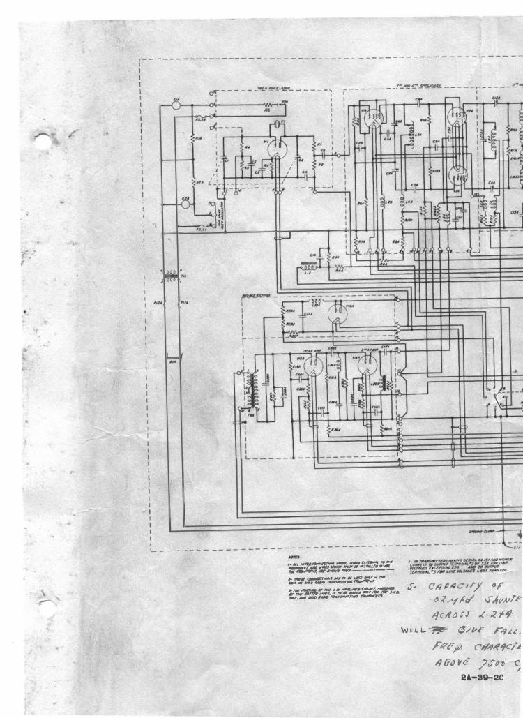
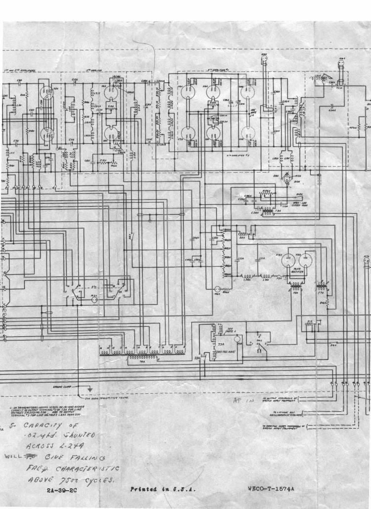
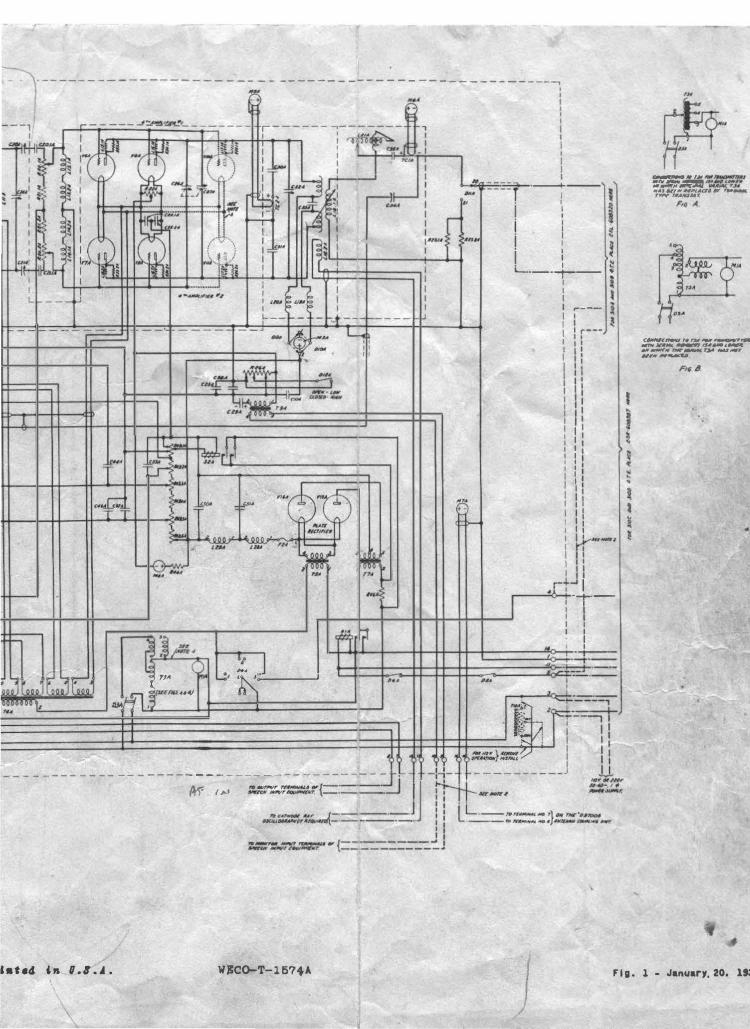
ot apparatus as quickly as posslble. A complete detailed schematic
diagram of all radio frequency, audio frequency, power and power con
trol circuits is given in this bulletin.
In case of trouble in any of the control or protection cir
cuits, the operator should remember that these circuits are inter
locked so that the failure ot one piece ot apparatus otten prevents
other pieces from functioning. For example, should the plate voltage
relay (SlA) fail to operate, the "High Voltage" switch (D6A), door
switch (D6A), and the door switch in the Antenna Coupl!ng Unit should
be investigated. Any one of these may be causing the trouble. This
method of checking through circuits should be continued until the de
tective pi�ce ot apparatus is located.
Trouble in the radio frequency circuits is usually caused
by improper adjustment. The first step in case ot trouble in these
circuits should be to see that all adjustments ar& in accordance w1 th
..
- 14 -
those described in this bulletin, as well as with the adjustments
r6corded in the station log.
SUrge Suppression Relay
Should relay S2A fail to operate as indicated by low (Approx
imately ?50 volts) "Plate Voltage� on meter ?.MA, adjust the slider tap
on R49.1A until the voltage between this tap and ground measures
approximately 100 volts when the transmitter is delivering its rated
output power. Under this condition relay S2A should operate a traction
ot a second after "High Voltage" s witch (D5A) is operated •
SPARE PARTS
The list of "Spare Parts'' on Table III is recommended as a
complement of spare equipment which DBY be purchased at the customer's
option. Spare electrolytic condensers are not reconmended as the
self life tmY be no longer than the service lite. These condensers
should be purchased only when replacements are to be made.
Detailed information is given in Table II which will be of
value in locating causes of improper operation.
nmnraERING SERVICE AND INFORMATION FOR
ORDERING REPLAC�
Engineering Service DBY be obtained through the nearest
Branch House ot the Graybar Electric Company, and authorization for
such service should be placed with them. In Canada, this service
may be obtained through the Northern Electric Company, Ltd., and in
other foreign countries with the International Standard Electric
Corporation.
- 15 -
Orders for replacement apparatus should specify the appara
tus designation (such as, R2B) shown on the drawings and usually
stamped on the apparatus as well as the name, catalog number, nameplate
data and serial number of radio transmitter and other pertinent in
fo:nnat ion which is ava ilable.
Instruction Bulletin No.
The Equipment Described in This Bulletin Has Designed and
Developed for the \iestern Electric Company
by
BELL TELEPHONE LABORA'roRIES
WESTERN ELXCTRIC COMPANY
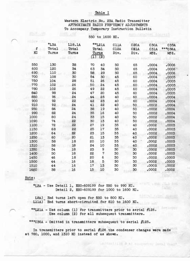
'!able I
Western Electric No, 23A Radio Transmitter APPROXIMATE RADIO FRE<'UENCY ADJUSTM!mTS
To Accompany Temporary Instruction Bulletin
550 to 1600 KC.
*L3A Ll.8.lA **L21A CllA C20A C30A C35A t Total Total Total Cl2A CllA C31A ***C36A
KC 'l\lrns Tuma Turns (l} (2)
Div. Div. Mtd. Mtd.
550 130 38 70 40 50 65 .0004 .0006 600 120 34 63 34 50 65 .0004 .0006 690 110 30 58 29 50 65 .0004 .0006 700 108 30 54 30 45 60 .0004 .0005 750 104 28 51 26 45 60 .0004 .0005 770 102 26 50 24 45 60 .0004 .0005 780 102 26 49 22 45 60 .0004 .0005 840 98 24 47 20 45 60 .0004 .0005 850 96 24 44 25 40 60 .0004 .0004 900 92 22 42 23 40 60 .0004 .0004 910 92 24 41 22 40 50 .0002 .0004 950 86 24 38 19 40 50 .0002 .0004 990 82 24 35 16 40 50 .0002 .0004
1000 80 24 33 15 40 50 .0002 .0004 1090 74 22 30 13 40 50 .0002 .0004 1100 72 22 27 19 35 40 .0002 .0003 1150 68 22 25 17 35 40 .0002 .0003 1200 64 22 23 15 35 40 .0002 .0003 1250 60 20 21 13 35 40 .0002 .0003 1300 58 18 20 10 35 40 .ooo� .0003 1310 58 18 24 10 35 40 .0002 .0003 1350 54 18 23 9 30 30 .0002 .0003 1400 50 18 22 7 30 30 .0002 .0003 1450 46 18 20 6 30 30 .0002 .0003 1500 44 16 18 5 30 30 .. 0002 .0003 1510 44 16 17 13 30 30 .oooa .0002 16C.0 38 16 15 10 30 30 .0002 .0002
!!2!!,:
*L3A - Use Detail 1, ES0-609199 tor 550 to 990 KC. Detail 2, ES0-609199 tor 1000 to 1600 KC.
I.SA) End turns lett open tor 550 to 800 KC. LllA)- End turns short-circuited tor 810 to 1600 KC.
r **L21A - Us� column (1) tor transmitters prior to serial 1126. Use column (2) tor all subsequent transmitters.
***C36A - Omitted in transmitters subsequent to serial #125.
In transmitters prior to serial #126 the condenser chal16eS were made at 780, 1000, and 1310 KC instead ot as shown.
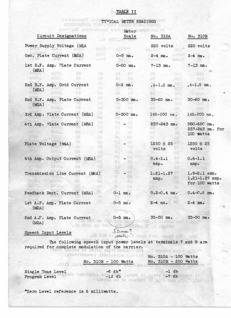
TABLE II
TYPICAL METER RFADIUGS
Circuit Designations
Power Supply Voltag& (Ml.A Osc. Plate Current (M2A)
let R.F. Amp. ?late Cu_rrent (M2A)
2nd R.F. Amp. Grid Current (M2A)
2nd R.F. Amp. Plate Current (M2A)
3rd Amp . Plate Current (M2A) 4th Amp. �late Current (M3A)
Plate Voltage (l.f4.A)
4th Amp. Output Current (�fl.A)
Transmission Line Current (M)A)
Feedback Rect. Current (M2A) 1st A.F. Amp. Plate Cur rent
(M2A) 2nd A.r. Amp. Plate Curr�nt
(M2A) Speech Input Levels
Meter Scale
0-5 ma.
0-50 ma.
0-2 m.
0-300 me.
0-300 ma.
0-1 ma.
0-5 me..
No. 310A
220 volts
2-4 me..
7-13 ma.
• 4-1.5 ma .
30-60 ma.
145-200 ma.
237-243 ma.
1250 ± 25 volts
0.4-1.1
amp .
1.21-1.27 amp ..
0.2-0. 4 ma.
2-4 ma.
35-50 ma.
No. 310B
220 volts
2-4 ma.
7-13 m.
.4-1.5 ma •
30-60 m.
145-200 ma.
580-620 ma. 237-243 rm. for 100 watts
1250 ± 25 volts
0.4-1.1
amp.
1.9-2.1 amp. 1.21-1.27 amp. for 100 watts
0.4-0.6 ma.
2-4 ma.
35-50 ma.
The following speech input power levels at tenninals 7 and 8 are required for complete modulation of the carrier.
Single Tone Level Program Level
No. 310B - 100 Watts
-6 db* -12 db
*Zero Level r�ference is 6 milliwatts.
No. 310A - 100 Watts No. 310B - 250 Watts
-1 db -7 db
•
•
. ·
r
..
- a -
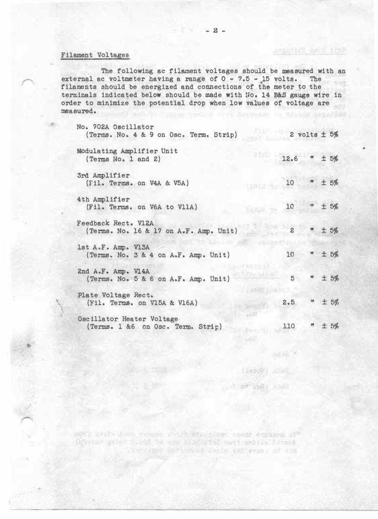
Filament Voltage&
The following ac filament voltages should be measured with an external ac voltmeter having a range of 0 - 7.5 - 15 volts. The filaments should be energized and connections of the meter to the terminals indicated below should be made with no. 14 B&S gauge wire in order to minimize the potential drop when low values of voltage are measured •
\ \ ..
No. 702A Oscillator (Terms. No. 4 & 9 on Osc. Term. Strip)
Modulating Amplifier Unit (Terms No. 1 and 2)
3rd Amplifier (Fil. Terms. on V4A & V5A)
4th Amplifier (Fil. Terms. on V6A to VllA)
Feedback Rect. Vl2A (Terms. No. 16 & 17 on A.F. Amp. Unit)
1st A.F. Amp. Vl3A (Terms. No. 3 & 4 on A.F. Amp. Unit)
2nd A.F. Amp. Vl4A (Terms. No. 5 & 6 on A.F. Amp. Unit)
Plate Voltage Rect. (�'il. Terms. on Vl.5A &. Vl6A)
Oscillator Heater Voltage (Terms. l &6 on Osc. Term. Strip)
2 volts ± 5%
12.6 " ± 5%
10 " ± 5%
10 It ± 5%
2 " ± 5%
10 " ± 5%
5 " ±�
2.5 " ± 5%
110 " ± 5%
;i: .
- 3 -
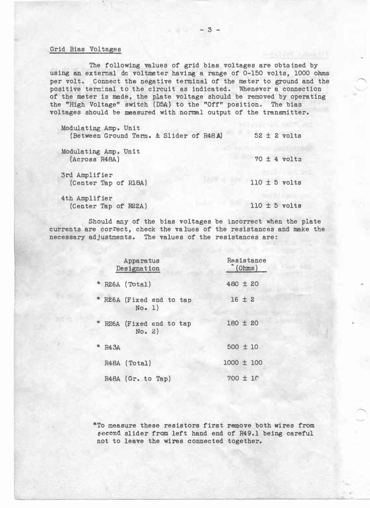
Grid Bias Voltages
The following values of grid bias voltages are obtained by using an external de voltmeter having a range of 0-150 volts, 1000 ohms per volt. Connect the negative terminal of the meter to ground and the positive term:!.nal to the circuit as indicated. Whenever a connection of the meter is made, the plate voltage should be removed by operating the "High Voltage" switch (D5k) to the "Off" position. The bias voltages should be measured with norrm.l output of the transmitter.
Modulating Amp. Unit (Between Ground Tenn. & Slider of R48�
Modulating Amp. Unit (Across R48A)
3rd Amplifier (Center Tap of RlBA)
4th Amplifier (Center Tap of R22A)
52 ± 2 volts
70 ± 4 volts
110 ± 5 volts
110 ± 5 volte
Should any of the bias voltages be incorrect when the plate currents are correct, check the va lues of the resistances and make the necessary adjustments. The values of the resistances are:
Apparatus R�sistance Designation •(Ohms)
* R26A (Total) 480 ± 20
* R26A (Fixed end to tap 16 ± 2 No. 1)
* R26A (Fixed end to tap 180 ± 20 No. 2)
* R43A 500 ± 10
R48A (Total) 1000 ± 100
R48A (Gr. to Tap) 700 ± lC'
*To measure these resistors first remove both wires from seeond slider from left hand end of R49.l being careful not to leave the wires connected together.
- 4 -
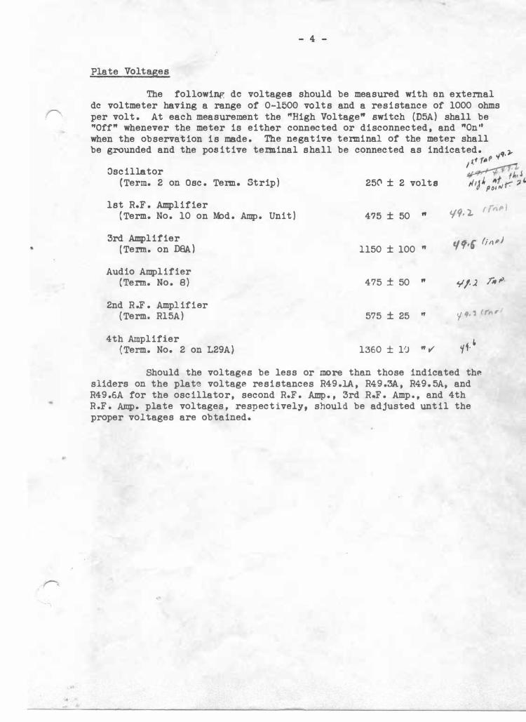
Plate Voltages
The following de voltages should be measured with en external de voltmeter having a range of 0-1500 volts and a resistance of 1000 ohms per volt. At each measurement the "High Voltage" switch (D5A) shall be "Offft whenever the meter is either connected or disconnected, and ftQn'' when the observation is made. The negative terminal of the meter shall be grounded and the positive tenninal shall be connected as indicated. q.r
t 1 ft11f' ., Oscillator
(Term. 2 on Osc. Term. Strip)
1st R.F. Amplifier {Term. No. 10 on M:>d. Amp. Unit)
3rd Amplifier (Term. on OOA)
Audio Amplifier (Term. No. 8)
2nd R.F. Amplifier (Term. Rl5A)
4th Amplifier (Term. No. 2 on L29A)
25C' ± 2 volts
475 ± 50 "
1150 ± 100 ft
475 ± 50 ft
575 ± 25 "
1360 ± 10 "v'
1 � . . -rn �+.' f/1•S "'J" ,,f r. :J' po1rJ ·
'19· '- f{"PI
tf tf•f fjnPJ
¥/-.2 Ji, ,o.
'f '1• 'l rrn,.
'(f. �
Should the voltages be less or more than those indicated thA sliders on the plate voltage resistances R49.1A, R49.3A, R49. 5A, and R49.6A for the oscillator, second R.F. A.mp., 3rd R-F. Amp., and 4th R. F. Amp. plate voltages, respectively, should be adjusted until the proper voltages are obtained.
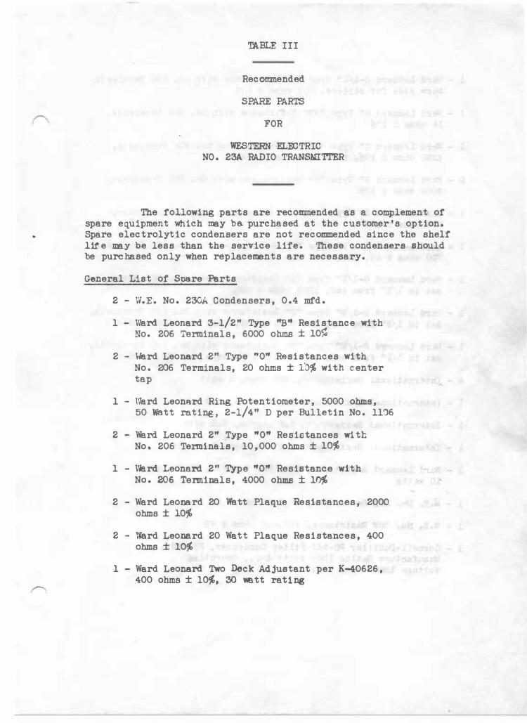
TABLE III
Recommended
SPARE PARTS
FOR
WESTERN EL:ro TRIC NO. 23A RADIO TRANSMI'ITER
The following parts are recommended as a complement of spare equipment which may b� purchased at the c ustomer's option. Spare electrolytic condensers are not reconnnended since the shelf lite my be less than the service life. These condensers should be purchased only when replacements are necessary.
General List of Snare Parts
2 - W.E. No. 230A Condensers, 0.4 mfd.
1 - Ward Leonard 3-1/2" Type "B" Resistance with No. 206 Terminals, 6000 ohms ± 10%
2 - Ward Leonard 2" Type "O" Resistances with No. 206 Terminals, 20 ohms ± lb% with center tap
1 - Ward Leonard Ring Potentiometer, 5000 ohms, 50 Watt rating, 2-1/4" D per Bulletin No. 11�6
2 - Ward Leonard 2" ,Type "O" Resistances with No. 206 Terminals, 10,000 ohms ± 10%
1 - Vie.rd Leonard 2" Type "O" Resistance with No. 206 Tenninals, 4000 ohms ± 10%
2 - Ward Leonard 20 Watt Plaque Resistances, 2000 ohms ± 10%
2 - Ward Leonard 20 Watt Plaque Resistances, 400 ohms ± 10%
1 - Ward Leonard Two Deck Adjustant per K-40626, 400 ohms ± 10%, 30 watt rating
,
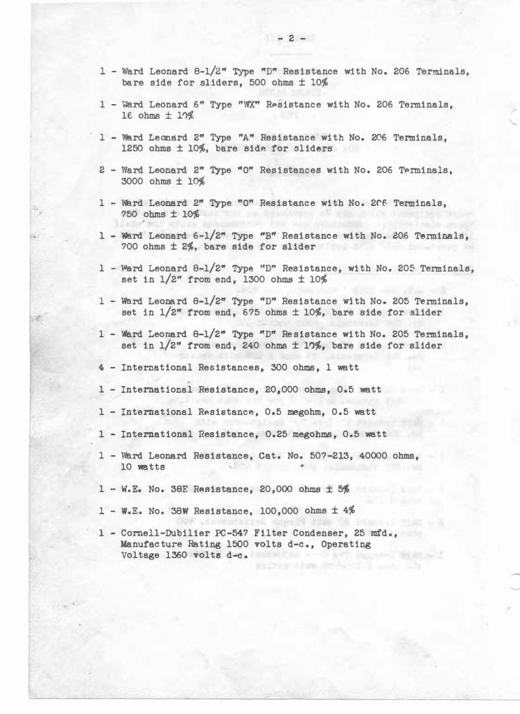
- 2 -
l - Ward Leonard 8-1/2" Type "D" Resistance with No. 206 Terminals, bare side for sliders, 500 ohms ± 10%
l - Ward Leonard 6" Type "WX" RPsistance with No. 206 Tenninals, le ohms ± 1'>%
1 - We.rd Leonard 2" Type "A" Resistance with No. 206 Terminals, 1250 ohms ± 10%, bare side tor sliders
2 - Ward Leonard 2" Type "O" Resistances with No. 206 T�rminals, 3000 ohms ± 10%
l - \18rd Leonard 2" Type "O" Resistance with No. 2r6 Terminals, 750 ohms ± 10%
1 - We.rd Leonard 6-1/2" Type "B" Resistance with No. B06 Tenninals, 700 ohms ± 2%, bare side for slider
l - Werd Leonard 8-1/2" Type ''D" Resistance, with No. 205 Terminals, set in 1/2" from end, 1300 ohms ± 10%
1 - Werd Leonard 8-1/2" Type "D" Resistance w1 th No. 205 Tenninals, set in 1/2" from end, 675 ohms ± 10%, bare side for slider
l - Ward Leonard 8-1/2" Type "D" Re sistance with No. 205 Tenninals,
set in 1/2" from end, 240 ohms ± 10%, bare side for slider
4 - International Resistances, 300 ohms, l watt
1 - International Resistance, 20,000 ohms, 0.5 watt
1 - International RAsistance, 0.5 megohm, 0.5 watt
1 - International Resistance, 0.25 megohms, 0.5 watt
1 - \'erd Leonard Resistance, Cat. No. 507-213, 40000 ohms, 10 watts
1 - w.E. No. 38E RABistance, 20,000 ohms ± � l - W.E. No. 38W Resistance, 100,000 ohms ± 4%
l - Cornell-Dubilier PC-547 Filter Condenser, 25 m:fd., Manufacture Rating 1500 volts d-c., Operating Voltage 1360 volte d-c.
--
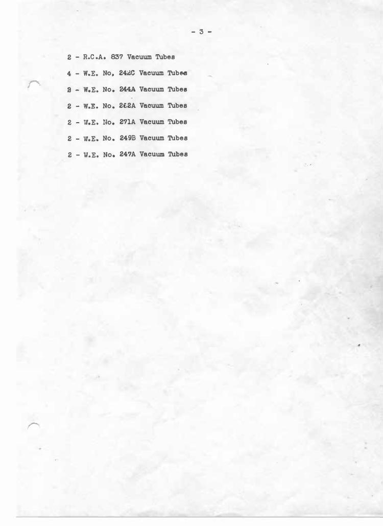
- 3 -
2 - R.C .A. 837 Vacuum Tubes
4 - W.E. Nop 24ic Vacuum TubNS
r-. a - W.E. No. 244A. Vacuum Tube•
2 - W.E. No. 2t2A Vacuum Tubes
2 - W.E. No. 2?1A Vacuum TUbes
2 - '11.E. No. 249B Vacuum Tubes
2 - W.E. No. 247A Vacuum 'l\lbes
i'� .. . I
'·
\
r---------------------- - - --- --- - .. - -- ------ ---- - - - - - ---- - .
I I I I I I I I I
I I J I I I I I I � I I I I I I I
,�
d'r:- - - -- -� -"9L - ----, ' I I - I
- I .'
�----• I
I
I � '. I I �I I .. ;rr :�, -�
,,, II I
I� U <If / c,� �·" /. _ ·, . - ---- . / " :
, ----
-t ,-( -;.-- - - -. � 7 - - - , - - _,
--0 -;]1! , .. ,. ;.. •i
• .ill ' m '" I ,
,�,
'---' -
I I
-�f .,, � ,,. -h.A
__ _!����-- - �-----L•41!"1
;;
-I T
I
I
I : -�-rl L. - - - •. - - - -- - - - - - - - - - - - - - - - - ---- - - -- - --- -- - --- -------'=. -,,-
-1 .. .-J J/'�F-- .... 1...,,. C.f....-.C 19,,. ..........-i; AM "'*1 ....,,. JllflN" 111&1/'lfUFI lllJNJtt ,. ,..,,,,,,,,., .,......,,.,.,, ____ _
l'-WM�_..,•NIAO.,.,.lllT/IJI .894. -· ..... ,...,.,,,,.,.,,.,,,,.,.,,, �������:r��#. !"--- Cl?/JACd) o;:-.-c.#lll MD,HI# l'Allt¥./lltllfT/Nrl �,.,_ . �:< v�c/. \J")u»I�
/1i..A� iJ ,(.,< f.f F"9,(.f, w1LL� <3/vr·
/'/?c·y.. C/1"'1,if"/C/� 1'l Ou v,: /�-n c
/ 2•-a�2c
----------- - ---------- --- -�-. ·-- ---- - - ---------- - - �- - -- - -----------------1·+) �·
�
:l��:�-���- -!--�:) .. �-�f - - -:.�t�� 1-�--�J�i·- -�1�;- [�----r!P�- -1 " � ! � - o '::st:! I '< < ' : <� :0 � �- .• : : �..,� J)�, :
� . .. �r • - ':I" r¥" I � ' I- I - � � I ·I - I ri•" lJI. ,: :l
l- ; :m• .,.. I : -?" � :! < _, f-t.I..! • ,I rJt-- I
t:tt::=t-:iH=" �utttl .,. J "' I � I 419ll .;;;,. rJ:' , - � �, I
-"'
1-� 1 : � �� : l"l·��.,. r-r M I I � - I : .. � i?f\. : !� :9n � / \ ! ,:"" �i� l !"-\f 11 I I ·-: \td I I ili.i! I HJ�t )H" I � I 'ff 1- . ':': 'l , _ I � II )' " l • I I 11 "' � 11 i.,'� ··,, I ff �· I ' ' L'.:1�==t===:::i I • - • • I I --··_j I ' : '" ,_ I g � t c • I J I J" '-) I I
_ h 1 1 l"'h I ' - I .. J l : � Lo- - -•• _,,_,, : .-:-� I : - " .... f! !L!-- :iU - : '---l--t- --t ---�---- :.i
--..... I I I \._
: :... ·-' I """" ..... b
' I i
·-��
"" (i" - - -'�· - �--' . .
( f I C ' ,, ·�
I I -·· .. I ' = !!-�-=+��.l-!_�_:-H"J..�r'-4'-----------....,
�
-� ---
,,.. l#J
,,.��! .... ' ..,,,,,,.
.... -
� .. I
' I>-
� � , 1 • "} , ) •.• -..--!"-.. ------ - - --- - ------- --- -- --------- - - - . -I�-
---- - --- --- - - --- -�;,
.. -.. �-;_;.;;,;,.:;------
A" . 1 �• .. WfJ/IW,,..,..,..,41.,,.{ __ . __ .JI H-,' J ,,._. �ll/l/fllV'� -·---..:..J I I I
C/:l/JAC11"/ o;:-• c:i :< v�o/. \J.Al/»1�� J'/ Cl(� .rJ ,( • .< y.-f
w1LL� (5,;v;: F"J.(.(/'1,. <3 //1,'•).J. C'//..,,,f'1C/Ef' ·J, /C "1 O,; v�: /:-re </" t E .r,
2A-8�2C '�'•t•4 '� 1.8.�.
l : :L. '9ur...,- ..,,. /----·-- I --,.,--t-·-- -- ·- I : . I I I I
==r.:.w� ., <==-=--=-====-:J
WJCC>-T-1574.A
I
I
' -
--
<-r;:
--------- ----- --------------�
- ,, -�-J.-... l;?, - I .---t-----T-----. I ----�f-----+--...
·� WC" : !:f"' -... ., 000 ........ 000
, , , _ ,,., '-� _ -.. ....
-
-� ::::f ·---r II • I
� 7 ' P-
I
I l i I . I � I I � I I � L---·+-- .. I I I !
I .----' i 1 I
I I I I I
I I I I I I I I
r--- �
I l I ' : -
I �--'
'
l j I ._rt I - ,-1·-: I I I n
. ;::,� . �· � '·· .J I TIA ( 1 ,_:, 1'.·;----�
l1? .. I ! '-l��--+----t-+--++--+-lf--+-----�-r· -r----.--+·--+---+-4f--+.-+-+-::: ::::::::!���-r--r---. -�---I I I �fl �1,.u ,,.. ... 1 n I �::01001,�'------' AM '-""''----�-+----..... -------�· �
It
----- -- --- ------------ - - --------- - - r-.--Af' I,.., �.:;.,�{==-==-� j
-:��=====---:-.J.
"""'1tllltr,_, M fM ,_........,, :::,,�� -:t=J�.t.* NAI N,/'llH.l'VACll}W,.......... TYN' TllAllSMT
F'4 A
Cl#'VCIMNI P# TM '9lt ,.,,,.,,,,,,... •fW Xlf14t ,,,.,.,,,, II# .... l..,_ Nf"'IM<'"' '"""'�,.,,. #!UJl#r .,#,,,,/lllUK6-0
&•hcl " ' u .8 .�. WJCC>-T-1574A
j FI g. 1 - January, 20. 19:
'°
r � a I:'-
I
"'4
"' :> .. .!!
Deaig, No,
ClA
C2A
C3A
C4A) C5A)
C6A) C7A) CSA)
C9A
ClOA
Cll.A) ClU) Cl3A ) Cl4A
Cl�A) Cl7A)
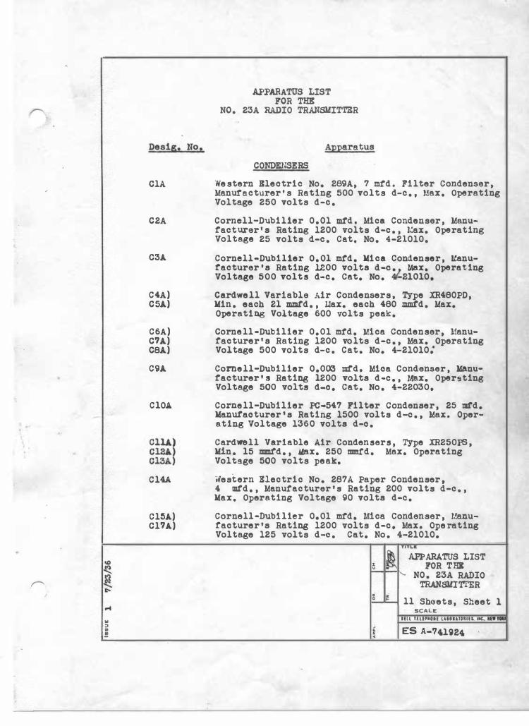
APPARATUS LIST FOR THK
NO. 23A RADIO TRANSMITTER
Apparatus
CONDENSERS
Western Kleotric No. 289A, 7 mtd. Filter Condenser, Manure.cturer•s Rating 500 volts d-c., Max. Operating Voltage 250 volts d-c.
Cornell-Dubil1er 0,01 mtd, Mica Condenser, Manufacturer's Rating 1200 volts d-c., Max. Operating Voltage 25 volts d-c. Cat. No. 4-21010.
Cornell-Dubil1er O.Ol mtd. Mica Condenser, Manufacturer's Rating 1200 volts d-c � 1 Max. Operating Voltage 500 volts d-c. Cat, No. 4'-21010,
Cardwell Variable Air Condensers, Type XR480PD, Min. each 21 mmt'd., uax. each 480 mmt'd. Max, Operating Voltage 600 volts peak.
Cornell-Dubilier 0,01 mtd. Mica Condenser, lfanufacturer' s Rating 1200 volts d-c., Max. Operating Voltage 500 volts d-c. Cat. No, 4-21010:
Cornell-Dubilier 0,003 mt'd, Mioa Condenser, Manufacturer• a Rating 1200 volts d-c., Max. Oper9ting Voltage 500 volts d-o, Cat. No. 4-22030,
Cornell-Dubilier PC•547 Filter condenser, 25 mfd, Manutaoturer's Rating 1500 volts d-c., Max. Operating Voltage 1360 volts d-o.
Cardwell Variable Air Condensers, Type XR25016, Min. 15 mmtd., .Max. 250 mmt'd. Max. Operating Voltage 500 volts peak.
Western Electric No. 287A Paper Condenser, 4 mtd., Manutacturer•s Rating 200 volts d-c., Max. Operating Voltage 90 volts d-c.
Cornell·Dubllier 0,01 mtd. Mica Condenser, Uanufacturer•s Rating 1200 volts d-c, Max. Operating Voltage 125 volts d-c. Cat, No. 4-21010,
TITl .. C
l APPARATUS LIST i FOR THI u
1'- NO. 23A RADIO TRANSMl'rl'ER . � 0 11 Sheets, Sheet
SCALE
1
llll ULIPMOIE UHUllllU, 11C.. NW,_ ; ES A-741924 . . •
� Lf) ......... � ....
N
" :> • !
Desig. No.
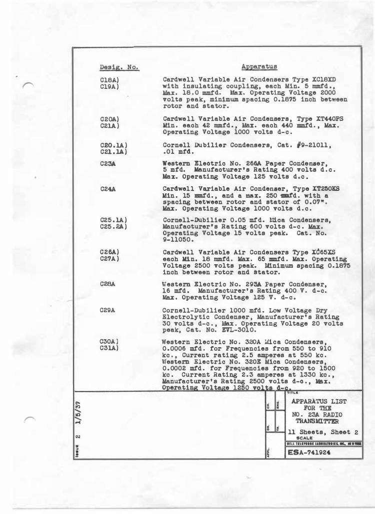
Cl8A) Cl9A )
C20A) C21A )
C20 . 1A ) C21 . 1A )
C23A
C24A
C25 . 1A ) C25 . 2.A )
C26A) C27A )
C28A
C29A
C30A ) C31A)
Apparatus
Cardwell Variable Air Condensers Type XC18XD with insulating coupling, each Min. 5 mmtd . , .Max. 18 . 0 mm!d. Max. Operating Voltage 2000 volts peak, minimum spacing 0 . 18?5 inch between rotor and stator.
Cardwe ll Variable Air Condensers , Type XT440PS .Min . eaoh 42 mmtd . , .Max. eaoh 440 mmtd . , Max .
Operating Voltage 1000 volts d-c .
Cornell Dubilier Condensers, Cat . 19-21011 , .01 mtd .
Western Eleotrio No. 2661. Paper Condenaer, 5 mtd. Ma.nutaoturer • s Rating 400 volts d . c . Max. Operating Voltage 125 volts d . c .
Cardwell Variable Air Condenaer , Type XT250KS .Min . 15 mm.td . , and a max. 250 1111td . with a spacing between rotor and stator or 0 . 07 " . Max . Operating Voltage 1000 volts d . c .
Cornell-Dubilier 0 . 05 mtd. llioa Condensers, Manutaoturer ' s Rating 600 volts d-c . Max .
Operating Voltage 15 volts peak. Cat . No. 9-11050 .
Cardwell Variable Air Condensers Type X665XS eaoh Min. 18 mmtd . Max . 65 mmtd . Max . Operating Voltage 2500 volts peak. Lfinimum spacing 0 . 1875 inch between rotor and �tator.
Western Electric No. 293A Paper Condenser, 16 mtd . Manuracturer ' s Rating 400 V . d-c. Max . Operating Voltage 125 v . d- c .
Cornell-Dub llier 1000 mtd . Low Voltage Dry Electrolytic Condenser , Manufacturer ' s Rating 30 volts d-c . , Max . Operating Voltage 20 volts peak, Cat. No. EVL-3010.
Western Electric No . 320A 1.U.ca Condens ers , 0 . 0006 mtd . tor Frequencies trom 550 to 910 kc . , Current rating 2 . 5 amperes at 550 kc . Vlestern Electric No. 320E Mica Condensers , 0 . 0002 mtd . tor Frequenc ies trom 920 to 1500 kc . Current Rating 2 . 3 amperes at 1330 kc . , .Manufacturer ' s Rating 2500 volts 4-o . , Max. Oneratina Vol taae 12�n vol�• d-�-TITL&
i i APPARATUS LIST u .. FOR THE
NO . 23A RADIO TRANSMI'r!'ER
i � 11 Sheets , Sheet SCAL.C
2
HU TlllNlll l&Hllltllll, ._ ··-£ c ESA-74192'
"
.. :i • !
Desig. No .
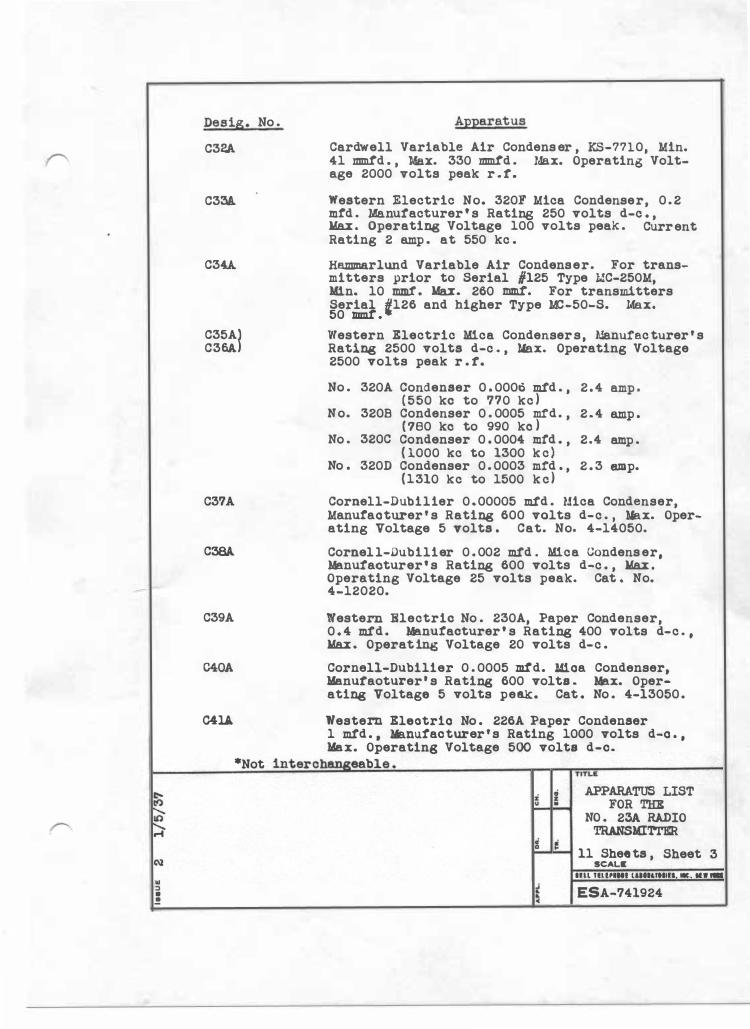
C32A
C33A
C34A
C35A) C36A)
C37A
C38A
C39A
C40A
Apparatus
Cardwell Variable Air Condens er , KS-7710, Min. 41 mm:t'd . , Max. 330 mm:t'd . Max. Operating Voltage 2000 volts peak r . r.
Western Electric No. 320F Mica Condenser, 0 . 2 mtd . Manufacturer ' s Rating 250 volts d-c . , Max . Operating Voltage 100 volts peak . Current Rating 2 amp . at 550 kc .
Hammarlund Variable Air Condenser. For transmitters prior to Serial #125 Type MC-250M, Min. 10 mmt . Max. 260 mmt. For transmitters Serial i126 and higher Type MC-50-S. Max. 50 mmr . Western Electric Mica Condensers, Manufac turer ' s Rating 2500 volts d-c . , ?lax. Operating Voltage 2500 volts peak r . r.
No . 320A Condenser 0 . 0000 mtd . , 2 . 4 amp . ( 550 kc to 7?0 kc )
No. 320B Condenser 0 . 0005 mfd. , 2 . 4 amp . ( ?80 ko to 990 ko )
No . 320C Condenser 0 . 0004 mtd . , 2.4 amp . ( 1000 kc to 1300 k c )
No . 320D Condenser 0 . 0003 mfd . , 2 . 3 amp. (1310 kc to 1500 k c )
Cornell-Dubilier 0. 00005 mtd . Uica Condenser, Manutaoturer ' s Rating 600 volts d-c . , Yax. Operating Voltage 5 Tolts . Cat. No. 4-14050.
Cornel l-Dubilier 0 . 002 mtd . Mica Condens er, Manufacturer' s Ratine; 600 volts d-c . , Max .
Operating Voltage 25 volts peak. Cat . No. 4-12020.
Western Electric No . 230A, Paper Condenser, 0 . 4 mtd . Manuracturer • s Ratine; 400 volts d-c . , Max . Operat ina Voltage 20 volts d-c .
Cornell-Dubilier 0 . 0005 mtd. Mi.oa Condenser, .Manuraoturer • s Ratine; 600 volts . Max. Operating Voltage 5 volts peak. Cat . No . 4-13050 .
041.A Western Eleotrio No . 226A Paper Condenser 1 mtd . , Manufacturer ' s Rating 1000 volts d-o . , .Max. Operating Voltage 500 volts d-c.
*Not interchallireable . TITLlt
i i APPARATUS LIST " . FOR THR
NO . 23A RADIO TRANSMITTER
a � 11 Shee ts , Sheet
SCALE 3
llll UUPIHI luellltllll, -., •• -
� � c ESA-741924
Deeig. No,
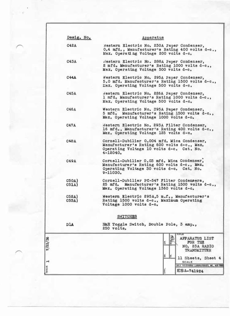
C42A
C43A
C44.A.
C45A
C46A
C47A
C48A
C49A
C50A) C51A ) C52A) C53A )
DU
Apparatus
·Nestern Electric No. 230A Faper Condenser, 0.4 m.td. , Manutacturer' a Rating 400 volts d-o . , Max. Operati ng Voltage 200 volts d-c.
.testern Electric No . 288A Peper Condenser, 2 mfd, Manufacturer ' • Rating 1000 volts d-c , , Max. Operating Voltage 500 volts d-c .
Western Bleotrio No. 295A Paper Condenser, 5 . 0 m.td. Uanutaoturer ' s Rating 1500 volts d-c . , Uax. Operating Voltage 500 volts d-c .
Nestern Electric No, 226A Paper Condenser, l mtd, Manutacturer ' s Rating 1000 volts d-c . , Max. Operating Voltage 500 volts d-c,
Western Electric No, 295A Paper Condenser, 5 mtd; Manufacturer ' s Rating 1500 volte d-c. , Max. Operating Voltage 1000 volts d-o,
Western Bleotrio No . 293A l'ilter Condenser, 16 mtd, , Manufacturer ' s Rating 400 volts d-c . , Max. Operating Voltage 125 volts d-o,
Cornell-Dubilier 0 . 004 mtd. Mica Condenser, Manutacturer ' a Rating 600 volts d-c . , Max. Operat ing Voltage 10 volts d-c . Cat . No. 4-12040,
Cornell-Dubilier 0 . 03 mtd. Mica Manufacture r ' • Rating 600 volts Operating Voltage 30 volts d-o. 9-11030,
Condenser; d-c . , Max,
Cat, No,
Cornell-Dubilier PC-547 Filter Condene.era , 25 mtd, Manufacturer ' • Rating 1500 volts d-o , , Max, Operating Voltage 1360 volts d-c,
western llectr1c 295A,5 m,t, , Manutaoturer' s Rating 1500 volts d-c , , Maximum Operating Voltage 1000 volts d-o,
SWJTCH;SS
H&H Toggle Switch, Double Pole , 3 amp, , 250 volts,
� TIT�ARATOS LIST � � IPOR THE ' NO. 23A RADIO
TRANSmTTER
ll Sheets, Sheet 4 SCALE
Ull UUPllll UHIUHlll. llC., IR -
•
c:-I!) ........ V'> ,r--.. ........ r(
N .. :> • .!
Desig, No,
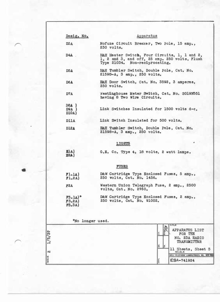
OOA
D5A.
D6A
D7A
D8A ) D9A ) DlOA)
DllA
DlU,
filJ 1'1.li) 1'1,2A)
1!'2A
1!'3,U)* 1'3.2A) 1!'3.3A)
Apparatus
Nofuze Circuit Breake r, TWo Fole , 15 amp. , 230 volts.
H&.H Heater SWitc•, Four Circuits, 1 , l and 2 , l , 2 and 3 , and off, 25 a.mp. 250 volt s , Flush Type 21034. Non-reciprocating.
H&.H Twllbler Switch, Double Pole , Cat. No. 21598-A, 3 emp. , 250 volts.
H&R Door Switch, Cat. No. 3592 , 3 amperes, 250 volts.
Westinghouse Meter Switch, Cat. No. S019N551 be.ving 8 Two Wire Circuits.
Link SWitches Insulated for 1500 volts d-c.
Link switch Insulated for 500 volts.
H&R Tumb ler SWitch, Double Pole , Cat. No. 21598•A, 3 a.mp, , 250 volts.
LIGHTS
G.X. co. TYpe 4, 18 volts, 2 watt lamps .
� D&W Cartridge Type Enclosed !'use s , 5 8lllp. , 250 volts , Cat, No, 1456.
Western union Telegraph ruse, 2 amp. , 2500 volts, Cot . No. 2760,
D&W Cartridge Type Enclosed !'uses, 2 amp. , 250 volts , Cat. No. 91002,
*No longer used. �. Tl�PARATUS LIST
t � FOR THE NO, 23A RADIO
TRANSMITTER
ll Sheets , Sheet 5 SCALE
llll TlUPllH UHUTllllS. MIC. llTI -
� ESA-741924 •
.. :> • !
Deslg. No.
LU
L2A
L3A
L4A,L5A.) L6A.,L7A)
L8A
L9. lA,L9 . 2A ) LlO. lA,Ll0. 2A)
Llli
Ll2A ) Ll3 .1A,Ll3.2A) Ll4.lA,Ll4.2A)
Ll5 . 1A , Ll5.2A) Ll6.lA,Ll6.2A) Ll7.l.A.,Ll7. 2A ) Ll8.lA)
Ll8.2A)
U9A) L20A)
L21A
L22A
L23A
L24A
Apparatus
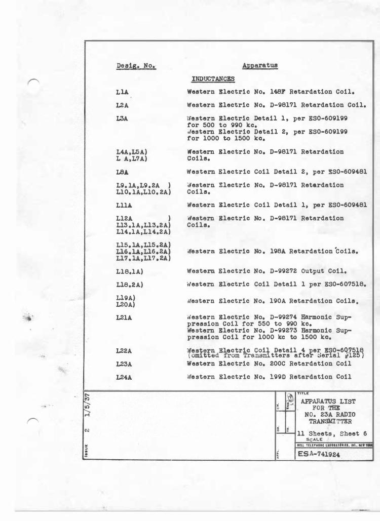
INDUCTANCES
Western Rlectric No. 148F Retardation Coil.
Western Electric No. D-98171 Retardation Coil.
\Y'estern Blectric Detail l , per ES0-609199 tor 500 to 990 kc. ·;1estern Electric Detail 2, per ES0-609199 ror 1000 to 1500 kc.
Western Blectric No. D-98171 Retardation Coils.
Western Electric Coil Detail 2 , per :!S0-609481
�estern Electric No. D-98171 Retardation Coils.
Western Xlectric Coil Detail l, per ES0-609481
Western Blectric No . D-98171 Retardation Coils.
iVestern Electric No . l98A Retardation ·cons.
Western Electric No. D-99272 Output Coil.
Western Bl'ectrlc Coil Detail l per ES0-607518.
tlestern .Electric No. l90A Retardation Coils .
Western Blectric No. D-99274 Harmonic Sup• pression Coll ror 550 to 990 ko. Western Electric No. D-99273 Harmonic Suppression Coil tor 1000 kc to 1500 kc.
·iteste:rn Electric Coil Detail 4 per RS0-6qJ518 ( om.1 tted from Tra n.\3ml tters after ::>erlal ;;125 ) Western Electric No. 200C Retardation Coil
tilestern Electric No. 1990 Retardation coil
� TITLE. i f.- APPARATUS LIST u M • FOR THE
.; . . c
NO. 23A RADIO TRANSMITT.!R
11 Sheets , Sheet 6 SCALE
Hll TllHIUf Ultll!Ulfl. llC., •W ....
.. ::> • !
Desig. No.
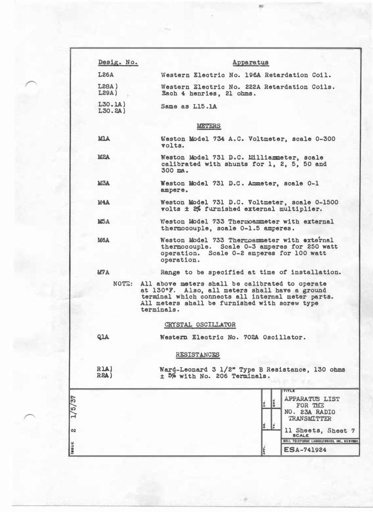
L26A
L28A ) L29A )
L30 . 1A ) L30 . 2A )
Apparatus
Western Eleotrio No. l96A Retardation Coi l .
Western Aleotric No. 222A Retardation Coils . Eaoh 4 henries , 21 ohms .
Same as Ll5 .1A
Weston Model 734 A . C . Voltmet er, scale 0-300 volts.
Weston l..t>del 731 D . C . W.lliallll!.eter, scale calibrated with shunts tor 1 , 2 , 5 , 50 and 300 ma .
Weston li:>del 731 D.c . Ammeter, scale 0-1 ampere .
M4A Weston Model 731 D . C . Voltmeter , scale 0-1500 volts ± 2J1, furnished external multiplier.
M5A Weston J.i:>del 733 Thermoammeter with external thermocouple , soale 0-1 .5 amperes .
M6A Weston M:>del 733 Thern;oe.mmeter with external thermocouple . Scale 0-3 amperes tor 250 watt operation. Scale 0-2 amperes for 100 watt operation .
'ir/A Range to be specified at time ot installation.
RlA) R2A )
NOTE: All above meters shall b e calibrated to operate at 130°7. Also, all meters shall have a ground terminal which oonneots all internal meter parts. All meters shall be furnished with sorew type terminals .
CRYSTAL OSCILLATOR
Western Eleotrio No . 702A Osci llator .
RESISTANCE.$
Ward-Leonard 3 1/2" Type B Resistance , 130 ohms ± � with No. 206 Terminals .
TITLa
s .; APPARATUS LIST z FOR THE u . NO . 23A RADIO
TRANSMITTER i " �
11 Sheets, Sheet SCALE
7 llll lllHltll UllUTlllH. MIC.. II•-
J ESA-741924 � � c
De sis. No1
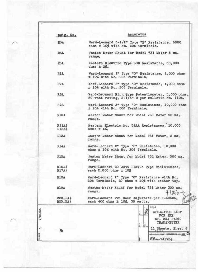
R3.A.
RU
R5A.
R6A.
R7A
R8A
R9A
RlO.A.
Rlli) Rl2A)
Rl3A
Rl4A
Rl5A
Rl6A) Rl7A)
Rl8A
Rl9A
R20.lA) R20 .2A}
'° � r!> � D-
..... � .. :> • �
Apparatus
�ard-Leonard 3-1/2" Type "B" Resistance , 6000 ohms ± l� with No. 206 Terminals.
Weston �eter Shunt tor l!odel 731 Meter 5 ma. range.
Western Xleotric Type 38D Resistance, 50 ,000 ohms ± 2�.
Ward-Leonard 2" Type "0" Resistance, 2 , 000 ohma ± l� with No. 206 Terminals.
Ward-Leonard 2" Type "0" Resistance, 4,000 ohma ± l� with No. 206 Terminals.
·;1ard•Leonard Ring Type Potentiometer, 5 • 000 ohms , 50 watt rating, 2-1/4" D per Bulletin No. 1106.
Ward-Leonard 2" Type "0" Resistance , 10, 000 ohms ± l� with No. 206 Terminals.
Weston Meter Shunt tor Model 731 Meter 50 ma. range.
Western Blectric No. 38AA Resistances,· 10 ,000 ohms ± '�· �eston Meter Shunt for Model 731 Meter, 2 ma. range.
Ward-Leonard 2" Type "0" Resistlllllce , 10 ,000 ohms ± 10� with No. 206 Terminals.
Weston Meter Shunt tor Model 731 lrieter, 300 ma. range.
�ard-Leonard 20 Natt Plaque Type Resi s tances, each 2 , 000 ohms ± l�
Ward-Leonard 2" Type "0" Resistance wi th No. 206 Termina ls, 20 ohms ± l� with center tap.
Weston Meter Shunt ror Model 731 Me ter 300 ma. range. � J ��1) -): . Ward-Leonard Two Deck Adjustats per K-40626, QJf" � each 400 ohms ± l�, 30 watts. i��
TITLE 1 / • � APPARATUS LIST u • 1'0R 'IHI
c c 0 �
NO. 23A RADIO TRANSMITTER
ll Sheets , Sheet 8 SCALE
Ill! IEllrllll UHIUHIU, llC.. MW,_ j � ESA-741924
� r;,-� II-
r4 .. :i .. !!
Desig. No,
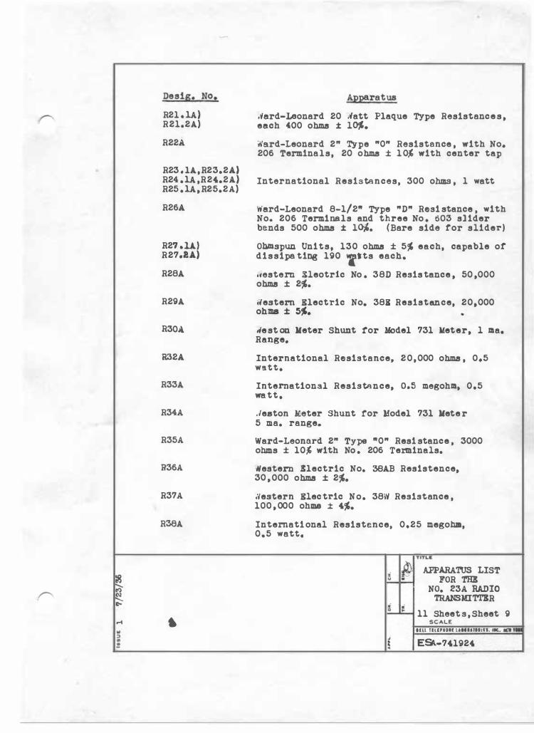
R21 . U) R21.2A)
R22A
R23 . lA , R23.2A) R24 .U ,R24.2A.) R25 . U , R25.2A)
R26A
R27 .U) R27.li)
R28A
R29A
R30A.
R32A
R33A
R34A
R35A
R36A
R37A
R38A
•
Apparatus
,'fard-Leonard 20 tlatt Plaque Type Resistance s , each 400 ohms ± l�.
�ard-Leonard 2" Type "0" Resistance , with No. 206 Terminals, 20 ohms ± 1 0% with center tap
International Resistances, 300 ohms , 1 watt
Ward-Leonard 8-1/2" Type "D" Resi stance , with No. 206 Terminals and three No . 003 sl ider bends 500 ohms ± l°". (Bare side ror slider)
Ohm.spun Units, 130 ohms ± 5� each, capable or dissipa ting 190 'f)ts each,
.�estern Kleotric No . 38D Resis tance , 50 ,000 ohms ± 2�.
Western Electric No. 388 Resistance, 20,000 ohma ± 5�. •
1ie st on Meter Shunt tor Model 731 Meter, l ma. Range,
International Resistance, 2 0 , 000 ohms , 0,5 W!itte
International Resistance, o.s megohm, 0,5 wa tt •
. leaton lleter ·shunt ror Model 731 Mete r 5 ma. range.
Ward-Leonard 2" Type "0" Resi stance , 3000 ohms ± 10% with No . 206 Terminals.
Nestern Electric No. 38AB Resistence, 30 , 000 ohms ± 2� •
.Vestern Elec.tric No. 38\V Resistance , 100 , 000 ohms ± 4�.
Internati onal Resistence, 0,25 megohm, 0,5 watt,
• ri 0 ..
TITLI: APPARATUS LIST
FOR THI NO. 23A RA.DIC
'l'RANSMITTKR
11 Sheet s , Sheet 9 SCALE
Hll nurHH UHllHllU, ... .. -
t ESll-741924 .
.. ::> • .!!
Deeig. No.
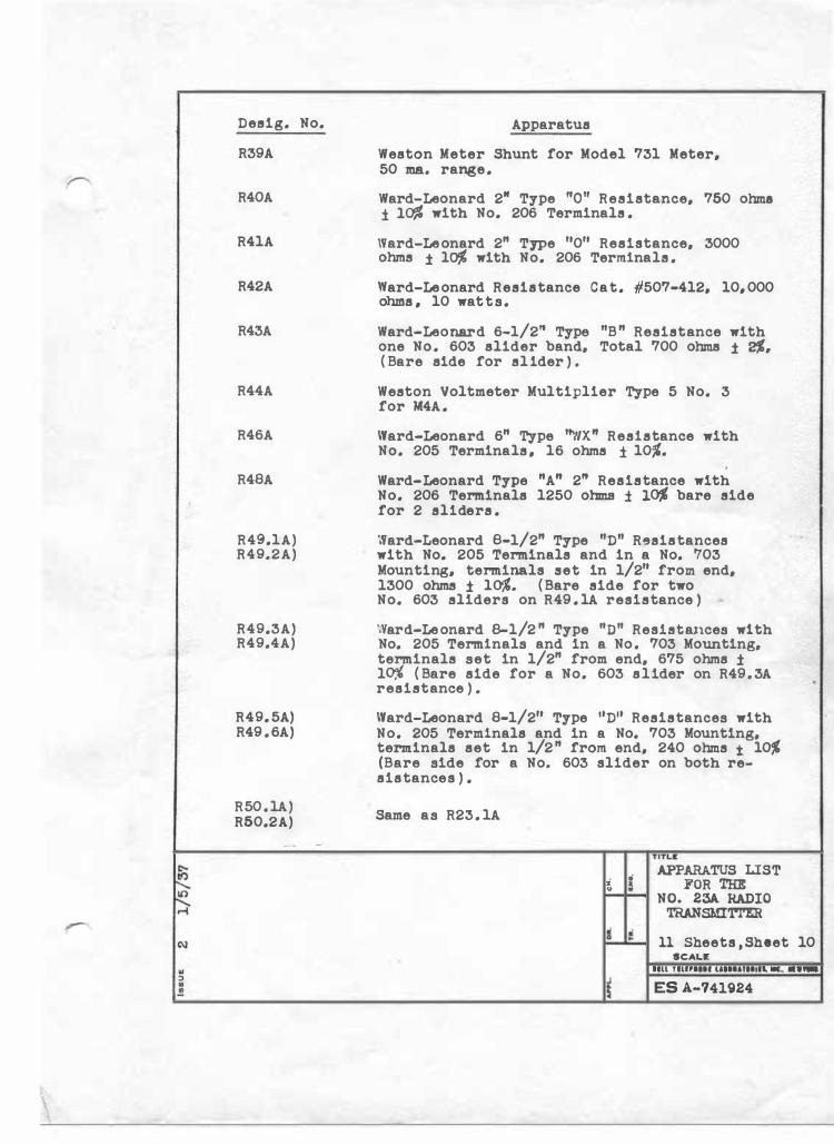
R39A
R40A
R41A
R42A
R43A
R44A
R46A
R48A
R49.1A) R49.2A)
R49.3A) R49.4A)
R49. 5A) R49 . 6A)
R50 . 1A) R50.2A)
Apparatus
Weston Meter Shunt for Model 731 Meter, 50 ma. range .
Ward-Leonard 2" Type "O" Resistance, 750 ohma ± lo% with No. 206 Terminals .
Ward-Le onard 2" Type 11011 Resistance, 3000 ohms ± la,( with No. 206 Terminals .
Ward-Le onard Resistance Cat. #507-412, 10, 000 ohnus , 10 wat t s .
Ward-Leonard 6-1/2" Type "B " Resistance with one No . 603 slider band, Total 700 ohms ± 2%. ( Bare side for sl ider ) .
Weston Voltmeter Multiplier Type 5 No. 3 for 'M4A .
Ward-Leonard 6" Type "WX" Resistance with No. 205 Terminals , 16 ohms ± 101'.
Ward-Leonard Type "A" 211 Resistance with No. 206 Terminals 1250 ohms ± lo% bare side for 2 sliders .
Ward-Leonard B-1/2" Type "D" R�sistances with No. 205 Terminals and in a No. �03 Mounting, terminals .set in 1/211 from end, 1300 ohms ± lo,(. ( Bare side for two No. 603 sliders on R49 . 1A resistance )
',Yard-Le onard B-1/2 " Type "D" Resi.sta.nces w1 th No. 205 Terminals and in a No . 703 Mounting, terminals set in 1/2" from end, 675 ohms ± l� ( Bare side for a No. 603 slider on R49 . 3A resistance ) .
Ward-Leonard 8-1/211 Type 11D11 Resistances with No. 205 Terminals and in a No. 703 Mounting, terminals set in 1/2 " from end, 240 ohms ± 10� (Bare side for a No. 603 slider on both resistances ) .
Same as R23 . 1A
i • " �
i =
TITLll APPARATUS LIST
FOR THE NO. 23A RADIO
TRANSMITTER
11 Sheets , Sheet 10 SCALE
llLL TILIPIHI UHIUHlll. llC.. ··-
ES A-741924
.. ::> • !
Deslg. No .
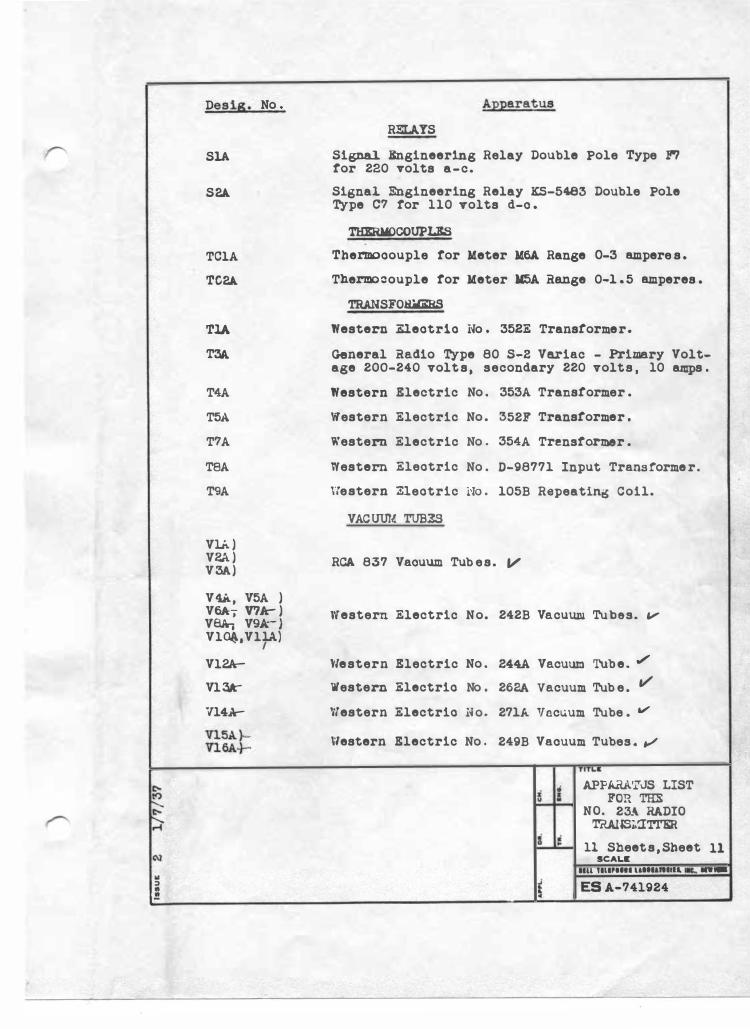
SlA
S2A
TClA
TC2A
TlA
TJA
T4A
T5A
T7A
TBA
T9A
VU ) V2A ) V3A)
V4k, V5A ) V6A-;- V? Jc- ) VSA, V9Jr ) Vl�1VllA) I Vl2A
Vl 3k" V'l4A
Vl5A }VlClA.}-
Apparatus
RELAYS
Signal. Rngineering Relay Double Pole Type F'7 tor 220 volts a-c.
Signal Engineering Relay KS-5483 Double Pole Type 07 tor 110 volts d-c .
THERMOCOUPLES Thermooouple tor Meter M6A. Range 0-3 ampere s .
Thermo�ouple tor Meter M5A Range 0-1 . 5 amperes .
TRANSFOR&imS
Western Eleotrlo No . 352E Transformer.
General Radio Type 80 S-2 Variac - Primary Voltage 200-240 volt s , secondary 220 volts , 10 amps .
Western Electric No . 353A Transformer .
'ilestern Electric No . 352F Transformer .
Western Electric No . 354A Tre.nstormer .
Western Eleotric No . D-98771 Input Transforme r.
\'le stern neotric rro . 105B Repeating Coil.
VACUUM TUBES
RCA 837 Vacuum Tub es. V
Western Electric No. 242B Vacuum Tubes. ""
\'/estern Electric No . 244A Vacuum Tube. .,/
Western Electrio No . 262A vacuum Tub e . v
Western Electrio No. 271A Yocuum Tube . v
Western Electric No . 249B Vacuum Tubes . v
TITI.•
i APPARA'i""uS LIST a FOR THE u NO. 23A RADIO
TaAlJSj.�TI'ER i ,; � 11 Sheet s,Sheet 11
SCALE llll TlllPIHl llllllllltll. - --
� ES A-741924