Embed Size (px)
Citation preview
H A NO 2190 P A G E - . C o X . I
Progress Peport No. 6
DZVELOPMEI\'T OF CON"3OL'S FOR
IN ALUMINUM WELDMENTS TIFIE- TEPIPERATUI'E CHAIACTERISTICS
CONT&ACT NO, NAS8-11930 Cont ro l No. DCNL - 5 - 3 0 - 12723 -01
Covering P e r i o d From SeFteaber 1, 1965 thru September 30, 1965
Prepared for
George C. Marshall S p a c e Flight Center h'atlonal Aeronautics and Space Administration
Huntsvi l le , Alabama
Gctoher IC:, 1965
Frepared by :
:ev iewed by :
&*i.gproved by :
https://ntrs.nasa.gov/search.jsp?R=19660014514 2020-05-25T10:34:50+00:00Z
I I .
Section
I
I1
I11
IV
TABLE OF CONTLFTS
Abstract
Accomrl i shmen t s Fret-I ous lp !?@ported
- Page Number
i f i
f.O1 t h r u I .c3
Accomplishments During This Rerort P e r i o d If.Ol t h r u
I T .ct5
Anticipated Work for Hext ITI.@l only F e r i o d
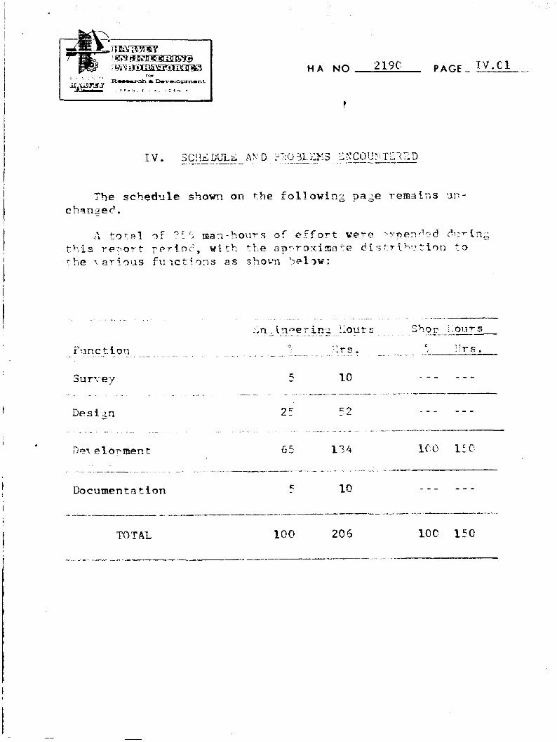
Schedule anc! TI-oblems Encountered IV.01 o n l y
This report contains a summary of accomnlishments during t h e first six months of a two p l r i s e research pros ?ram to develop methods, tooling concepts, and processt?~ to control t h e time-temperature characteristics in the weld and heat a f f e c t e d zone, in o r d e r to i r n y r m - e tensile prorerties and reduce porosity in a l i l m i r i u m weldrnents .
The results of the first c h a s e , which consisted of a s u n e y of literature and industry, were reported in . . u p s t . Equipment h a s been modifiec?, with instrumentation installed to monitor weldin,: t a r i a b l e s . elaluation of radioneters for application to t F e program w a s started. r.cfeience Weld- ments, without chilling, w e r e made in 5/16" a!nd 1/2" thick plate. Preliminary s tud ies , using 1Zqufd CCz, €ndPcated adequate chilling can De effected to alter w e l d thermal !at- t e r n s .
r

A . Summary
hting t h e four month p e r i o d of Phase I, 63 r e p o r t s of prev ious work ia re lated f i e l d s were r e \ * i e w e d , and 17 i n d u s t r i a l and dovernmental. organizations were contacted. i3y cambinin8 t h e pertinent information from this survey with t h e original t e c h n i c a l concept , a program plan was deve loped f o r the experimental work to be performed en Phase 11. Materials of long l e a d time delivery have been procured and preliminary modification of equipment has progressed to the point where experimental work can be initiated.
.
B , L i t e r a t u r e :?eviewed
The purpose of t h e survey was to obtain information whfch might be helpful i n t h e performance of this program, by avoiding d u p l i c a t i o n of effort and/or by sup?lementing the original Frogram concept.
Current a b s t r a c t bulletins published by the National Yeronsut ics and Space Adminis trat ion (ST.12) and by t h e Defense Documentation Center (TA-33) were checked for reports of work pertinent to firsion welding of aluminum, and significant reports were acquired for review. similar survey was made of applicable technical books and periodicals, including those of the -%merican Welding Society, the American S o c i e t y for Metals and the American I n s t i t u t e of Mining and Metallurgical Engineers. Particular emphasis was devoted to issues of the Welding Journal published during t h e past t e n years.
H A NO. 219c PAGE .
cast s t r u c t u r e w a s o 3 t a i n e 2 . '.I1 of t t l i s work was perfarmed on !?.P9scif1 +hick 2PI : and 2 V 2 ' ~ a l ~ i r n i ~ u m alloys. In one set .r.f exneriments r5e c5f.11 h a y s ( b Q t h toy and battom) were e m l e d wit,;^ haine at - - / r_"OF. In a StxnPiCJ set, for which data has j u s t 3een publ€ l ' ;hed , t%e c5fl.l bays were cooled wfth liquic! nttragen. Tn each c a s r , wr1c:i.l; w a s ;erformed after the ! - a r t s to 5e wplde? .~.nilcheCi a S~lCct~~c? t e m p e r a t u r e , -?O°F. and 2 E O O F . resrectively. ? i f f i c u l t ; r with, con2ensation of ma€stv.ulre on t h e p a r t s was o - e ~ c ~ r n e by enclosin: - t h e p a T t in a fleyihle r,l,astfc %zg contrainin; d r y a y j o n o r hellturn.
.i larse amount of work L ? j henn d m e and € 5 currently in r r o g r e s s to i m p r o t e the quality of welhents i n aerospace comFonents f a b r i c a t e d from aluminum. i l t h o u z h only a few specific s t i l l d i e s hay e apparently been conducted on a l abo ra - tory basis for determining t h e effect of time-temperature on prorerties of weldments, a good many of t h e process controls adopted for shop welding are aimed in t h e direction of con- trol ling thermal Tatterns.
D. Exwrimental Program - ---A
T h e Pxperimental nrogram will consist of two essential steps. The first vi11 be t3 C S t a b l ? S ) ; r e a f l s t f z target thermal patterns d e s i g n e d to i m y r o \ e the weld proFerties, and the second will be to d e l i i s e and test various means of proi. . lding the time-temperature controls r e q u i r e d to attain t h e optimum thermal patterns f o r wcld€ng t h e plate in two thicknesses, 1/2" and 5/16'', in each of two alloys, 201/r-T6 and 2219-T57. Welding will be performed in the horizontal position by the Semi-Automatic T I G process, using direct current straight polarity, on square butt f a i n t preparation, with 2319 filler wire. It i s contem7lated that cryogenic liquids and auxiliary h e a t sources will be used to alter thermel patterns during wPld€ng. Tensile tests and hard- n e s s sun-eys will be used to correlate mechanical ?Topert ies with thermal pattern.
I
Sixty-three reports were selected for review and were classified under three genera l s u 1 j e c t areas according to their principal interest to- this program: (1) Time- Temperature Studies, (2) Heat Flow During Welding, and ( 3 ) General Welding Techniques.
No reported or unreported work was found which would indicate that any part of this program is a duplication of effort. A considerable amount of information was obtained which will facilitate the experimental s o r t i o n of the prosram, particularly t h a t work oerta€ning to h e a t t r a n s f e r analysis and specific wclsing techniques c u r r e n t l y in use for fabricatin2 aerospace s t ruc tures by welding the particular m a t e r i a l s Znvolyed.
C. Oroanizations -*. A x - + ---- Contacted
Those argantzations and individuals who were considered to be i n ~ o l ~ e d in work related to this proqram were con- tacted for personal interview or for interview by telephone. The cooperation was excellent, and in some cases specLa1 data were furntshed and tours of plant facilities were ar- ~ a ~ g e U + in generai, a great d e a l of interest was expressed in this program.
7 -a-
It appears that at the present time, no specific work is in progress to develop d a t a in addition to that already reported in the literature for development of the-tempera- ture controls or theoretical heat flow information for welding of aluminum alloys.
However, in some work recently completed at Frankford Arsenal it was determined that three significant trends were noted in the microstructure which indicate the merit of the use of super-chilling during welding of aluminum: (1) the amount of micro-porosity was substahtially lessened, ( 2 ) the width of the zone of grain boundary melting at the interface was reduced apnreciably, and (7 ) a finer grained
11. ACCOMPLISHMEETS DUFIHG THIS REPORT PERXOD ---_ __ _ - ~ ____-
A . Summary
The princ€pal ef fort during this reporting period was devoted to finalizatCon of equipment modification, and instrumentation of principal welding varia5les. Prelimin- ary steps were taken for elaluation of infrared radiometers applicable to the program. V-l<'ing of 201/t-T6 plate without special chillin?, b u t with mo-iftored welc'ing ariahles w a s begun. Indtial erperiments or) chilling indicatee t%it liquic' CQz is c a p a 3 l e Q € extTactiQ2 a cufficient rlrnoazt of !:ea? to a l t e r ?'*,e t'?r.rm.il att terns in t h e wgldment.
&. t: 'lorjif ication of 3 p i ; m e n t __I
The weldin:. equipment WAS s 1 q p l e m e n t e l onc' moi1i.fit2b S O t 5 a c experimental welSi?; could bo s t a r t e d . 14c?i+ional mo~li.ficstlons w e ~ e nffectec' t o pro' ic'e h e a t r : , = t r a c c f o n from the Sack side of the weld means of liquid G L 2 j e t s , and for scaxning t h e w ~ l d ares ' 2 ~ means of infra-ad rac4fometers to measure thermal patterns.
a. - General
Equiyment h a s been set up so that weldin; c a n be performed in the "free" state in the horizontal position. Test panels 12" x 48" tire wslded from one s i d e only, using the square butt Edge preparation. Ifelium shielding gas is used on the arc s i d ~ , a n d 2313 filler wire will be used as required to obtain acceptakle bead contour.
b. Weldinn P 9 w e r Supply .. ---a-
A duplex Miller DC rectifier type welder, M3del KO. 6C)O!12@0, with superimposed high frequency, is used to supply t h e welding current.
c. Side Seam and Carriage System
A 12 ft. Berkeley-%\is System M d e l No. TC4 has been mounted on a rectangular support frame fabricated from 2-112" diameter tubular s tee l p l ? a which is anchored t o t h e f l o q t and to the bui1dCng structural members. The s i d e beam ca r r l age s p e e d € s controlled by an electrontc governor (MDdel EG-3) for travel s p e e d s r a n g i n g from 4 . 4 t o 72.01 inches per m i n u t e .
d. Welding Torch
in Alrco HP-ZOA Heliweld h o l d e r with metallic nozzle of S / 8 " and 1/2" a t i f i c r s has hepn adap ted f o r sernC- automatic welding us ing F!^,2" and ?./I;", 29 thor-fated tungsten electrodes.
e. Wire Fped
'.n ',irco fCller w i r e feed w i t h w C r e pQsitioner hzen Ins t ; r l l ec! OR the car r fase s y s t e m and f C t t e d f Q r
?/!it+" and 1'16** wiye.
f.
The f i x t u t e for ~ o s i * i . o c i n ~ t5e w e l r l p a q c l s in t h e horizontal w s i t i o n cmsis t s 3f a frame f a b r i c a t e ?
inches on each side Q € the w;llC! centerline. The Fanels a r e clamped to the fixture by means of angle clamps which wete machPned for each th€ckness.
from I,'&': x zt 1 1 y ? " a n s l e i ron - , w i t h a "f+ee" a-ea qf
2. Chilling System -__I-
Jets of -7ariDus orifice s ize , flexible hose, and a 251! l b . tank of 1LquCd C02 were obtained. tn attachment bracket for p~sitlonlng tie j e t s was mounted on t h e back s i d e of t h e weld carriage system. The location and number a€ i e t s are ad3ustabl-e .
d J
C. Instrumentation
1. General
Instrumentation has been set up to monitor a l l L a r i - a b l e s which are sisnificant to this program, i n c l u d i n g weld- i n g s p e e d , weldins current, and t i n e - t e q P T a t u r e p a t t e r n s .
3n oytictil tsc5mneter, u t i 1 i z i . n ; lizht reflecttons from tho carriage 6 r i . e motor shztf t , is uscd to monitor welding s p e e d . Ttre te.flectrc2 l i i h t i s diI-ecr.r.6 i ~ ~ t q a photocell, the signal from w5ich is con7 e r t e d i n t o TCY olu- t i o n s per m i n u t e hy a Fiewlett-Fackard Fre>q!?ency X-.';etc.r, Il3del ZQCC. This motor speed is then c a l i i r a t e d in t e r m s Qf t ra - .e l srepd in inches per m t n u t e .
4 . T i m e - Temcerature - -
&'\ Leeds 6 V'nrthrup SFeedornar 12-channel recorder was modified to accomodate t \e required +crnger.atxr.e Fafige ( - 3 O C to 2100°F) , using chromel-constantan thermocouples.
X Huggins Mark I Infrascope (infrared radiometer) and a Barnes scanrtllng radiometer (also i n f r a r e d ) were ob- tained for evaluation. Se\ .eral other manufacturers of similar non-contact tpmperature m e a 5 9 ~ i n g systems were a l s o c o n t a c t e 6 . F r e l i m i n a r y e-. a l l ~ a t i D n : i n c ' i t a t e t h a t t'?e i n - f r a r e d radiometclrs will be 13seful in transient w e l d tempera- tures c?grtss w-. ldin; . 1-42 to t l ie i t p.?rtrc.mel;; rapid Y ~ S ~ O P S :
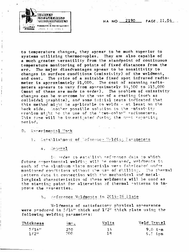
t o temperature changes, they appear to 5e much superior to s y s t e m s u t i l i z i n g thermocouples. They are also capable of a much greater tersatility from the staandpofnt of continuous temperature monitoring of p o i n t s of fixed d i s t a n c e s from t h e arc. The major disadvantases ap?ear to b e s e n s i t i v i t y to changes in sur face c o n d i t i o n s (emissivity) of the weldment, and cost . The price o f a s u i t a b l e f i x e d spot infrared radlo- meter i s apnroximate ly S1,COO. The c o s t of scanning radio- meters apnears t o vary from apnroximately SgIz,5OC t o $15,@0G (most of these a r e made t o order). The pro5lem of e m i s s i v i t y ct?an,zes cart be oyercome bv t h e *is4 of a cqat€ng (suctl a s c o l l o i d a l Zraphite), and s ~ m e i T l i ' L 2 1 tests € n ? i c a t e d t h a t t%is method mi.2 '7 t !,e a p r l l c a l l e t 9 welds - at least 3n t h e 1,ack s i d e . .not'-cr y3ssiF;le S D ? t l r i s n ~ r , &-'IF? -n?ssC* it;;
T'iis c-me will kc i n - esti - . a t e < c'..;r€:1:- t%e ~ ; r . * r t ~ . ? : o ~ t L q ; - yse of t h e ' L t n o - c ~ t ~ . - ' ' -ac!iomete-s.
~ e r i 3 d .
??clc'ments of s a t i s f a c t o y y physical ap-eaTance were produced in 5/1C1~' thick an$ l/Z" thick p l a t e us in2 the following w e l d i n 2 parameters :
I
T%tes.o wpldrnents w t l ! 3e evamincd a n d tested .$urin~ the next reportin3 perto?,
During t h e next repr>-t in; perf.r>d, i_t 1 s eypectec? t h a t thermal patterns and properties will be pstab l t shed for unchilled w e l d m e r l t s : PT*afgJnt ion of ra8ir)rne ters will %e contfnued; and t h a t I n i t C a l thermal patteTns ,nl terPd bv chi l l€nlg , wCll h e prociueect.
I
. . .
. , .~ -. . = _ . . - . r . 3 ela-men t
. -.
10
1714