Embed Size (px)
Citation preview
N o . 1875
HIGH-TEMPERATURE AND HIGH-PRESSURE STEAM LINES
B y B . N. B r o id o , N ew Y o r k , N. Y .
Member of the Society
The pronounced tendency of modern power-plant designers to use high superheat and high pressure, as well as the recent extensive use of highly superheated steam in process work, lead the author to make a renew of the available data and formulas on radiation and friction losses in pipe lines. A ll tests to determine the radiation losses of pipe lines carrying high temperature steam made in this country have been practically exclusively with electrically heated pipes. This paper gives results and analysis of tests made with superheated steam flowing through a pipe line. The heat-transmission coefficients of bare and covered pipes at different steam velocities, various superheats, and pressures are given. Suggestions are made regarding steam velocities to be selected in order to transmit steam more economically.
The formulas available at present for figuring the friction losses of steam in pipe lines are limited to the range for which they were established, or for comparatively low pressures. Corrections of these formulas are shown in this paper, based on observations of a pipe line carrying high-pressure steam, which corrections may be used by designers of high-pressure power plants in dimensioning their pipe mains.
The paper further treats of pipe lines carrying superheated steam for other purposes than power. Recommendations as to the velocities or pipe sizes to be chosen are given, as well as a few examples from practice to show how those velocities were advantageously applied.
rJ^HE use of superheated steam in power plants, as well as for various kinds of process work, has become.so extensive during recent
years that it is hardly necessary to enlarge on its advantages. The fuel saving effected by the use of superheated steam, the low maintenance cost of turbines using it, and the numerous advantages it has in various kinds of process work are some of the factors which have helped to assign to it the important position it now occupies in the opinion of technical men.
2 One of the phases in which engineers, power-plant operators, and managers are naturally interested in this connection is that of
Presented at the Annual Meeting, New York, December 4 to 7, 1922, and a meeting of the Metropolitan Section, January 4, 1923 of T h e A m e r ic a n So c ie t y o f M e c h a n ic a l E n g in e e r s .
1199
1200 H IG H -TE M PER A TU R E AND H IG H -PR E SSU R E STEAM L IN E S
conducting superheated steam through pipe lines. Very little, however, has been published in this country on the subject.
3 The recent tendency in designing of power plants, particularly those of large size, is toward high pressures. The high temperatures and high pressures involve new problems, among others being that of proportioning the pipe lines. A study of the losses of heat and pressure in pipe lines carrying highly superheated and high-pressure steam at the present opportune time will aid the designer in dimensioning the steam lines.
4 The field is very large, and this paper will therefore be confined to the discussion of —■
a Radiation losses in pipe lines carrying superheated steam b Resistance to the flow or pressure drop of superheated
steam in pipe lines c The most advantageous steam velocity, particularly for
high-pressure lines; and d Other features to be taken in consideration in designing
pipe lines for transmission of superheated steam of either low or high pressures.
RAD IATIO N LOSSES IN P IP E L IN E S CARRYING SU PER H EA TED
STEAM
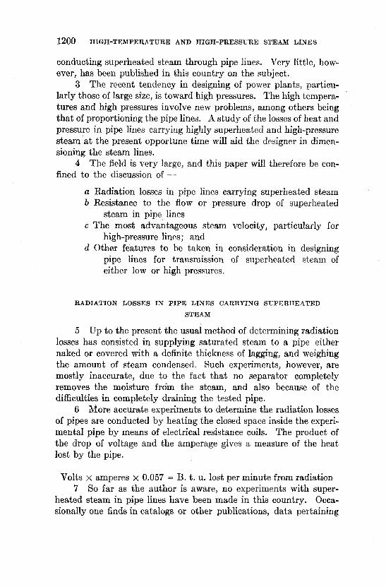
5 Up to the present the usual method of determining radiation losses has consisted in supplying saturated steam to a pipe either naked or covered with a definite thickness of lagging, and weighing the amount of steam condensed. Such experiments, however, are mostly inaccurate, due to the fact that no separator completely removes the moisture from the steam, and also because of the difficulties in completely draining the tested pipe.
6 More accurate experiments to determine the radiation losses of pipes are conducted by heating the closed space inside the experimental pipe by means of electrical resistance coils. The product of the drop of voltage and the amperage gives a measure of the heat lost by the pipe.
Volts x amperes X 0.057 = B. t. u. lost per minute from radiation7 So far as the author is aware, no experiments with super
heated steam in pipe lines have been made in this country. Occasionally one finds in catalogs or other publications, data pertaining
B. N . BROEDO 1201
to radiation loss with superheated steam. These data, however, were obtained with electrically heated pipes, and it was assumed that the radiation from a pipe carrying superheated steam of a certain temperature is the same as from a pipe heated up by an electrical resistance to the same temperature.
8 The author has had the opportunity to study this subject and to examine the results of tests conducted in Europe in which
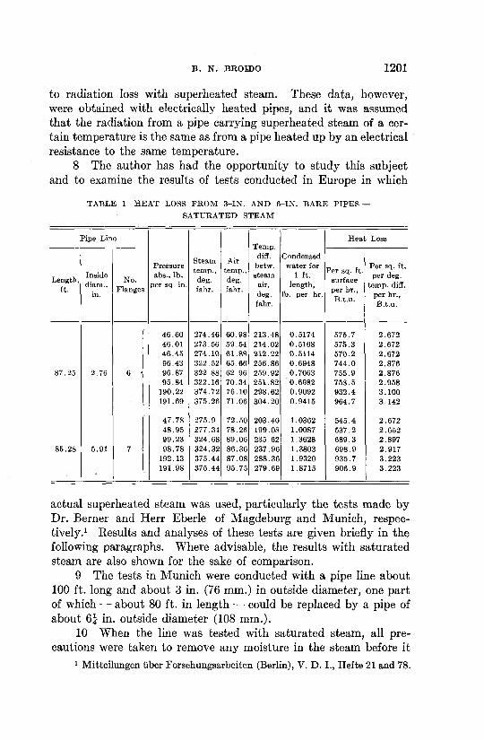
TA BLE 1 H E A T LOSS FR O M 3 -IN . A ND 6 -IN . B A RE P IP E S — SA TURA TED STEAM
Pipe Line
Pressure abs., lb.
per sq. in.
Steamtem p.,
deg.fahr.
Airtem p.,deg.fahr.
Temp.diff.betw.steam
air,deg.fahr.
Condensed w ater for
1 ft. length,
lb. per hr.
H eat Loss
Length,ft.
Insidediam.,
in.
No.Flanges
Per sq. ft. surface per hr., B .t.u .
Per sq. ft. per deg.
tem p. diff. per hr., B .t.u .
46.60 274.46 60.98 213.48 0.5174 575.7 2.67246.01 273.56 59.54 214.02 0.5168 575.3 2.67246.45 274.10 61.88 212.22 0.5114 570.2 2.67296.43 322.52 65.66 256.86 0.6948 744.0 2.876
87.25 2.76 6 i 96.87 322.88 62.96 259.92 0.7063 755.9 2.87695.84 322.16 70.34 251.82 0.6982 758.5 2 .958
190.22 374.72 76.10 298.62 0.9092 932.4 3.100191.69 375.26 71.06 304.20 0.9415 964.7 3.142
47.78 275.9 72.50 203.40 1.0362 545.4 2.67248.95 277.34 78.26 199.08 1.0087 537.2 2.65299.23 324.68 89.06 235.62 1.3628 689.3 2.897
85.28 5.91 7 98.78 324.32 86.36 237.96 1.3803 698.9 2.917192.13 375.44 87.08 288.36 1.9320 935.7 3.223191.98 375.44 95.75 279.69 1.8715 906.9 3.223
actual superheated steam was used, particularly the tests made by Dr. Berner and Herr Eberle of Magdeburg and Munich, respectively.1 Results and analyses of these tests are given briefly in the following paragraphs. Where advisable, the results with saturated steam are also shown for the sake of comparison.
9 The tests in Munich were conducted with a pipe line about 100 ft. long and about 3 in. (76 mm.) in outside diameter, one part of which — about 80 ft. in length — could be replaced by a pipe of about 6 | in. outside diameter (108 mm.).
10 When the line was tested with saturated steam, all precautions were taken to remove any moisture in the steam before it
1 Mitteilungen fiber Forschungsarbeiten (Berlin), V. D . I., Hefte 21 and 78.
1202 H IG H -TE M PER A TU R E AND H IG H -PR ESSTJRE STEAM L IN E S
entered the pipe line. In order to determine the radiation losses in a pipe line it is necessary to know the amount of steam condensed in the line. A few preliminary tests showed that with increased
and Air,Deg. rahr.
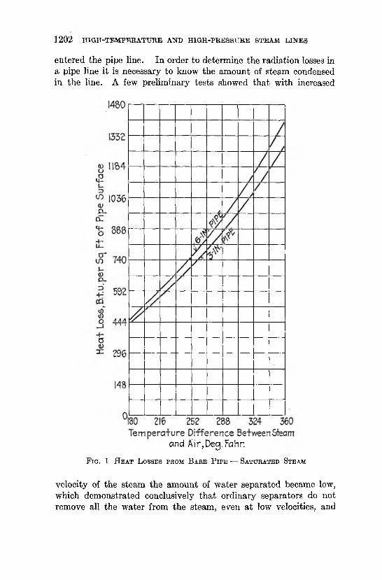
F ig . 1 H e a t L o s s e s fr o m B a r e P ip e — Sa t u r a t e d Stea m
velocity of the steam the amount of water separated became low, which demonstrated conclusively that ordinary separators do not remove all the water from the steam, even at low velocities, and
B . N . BBQIDO 1203
that the higher the steam velocity, the less reliable the separators. It was therefore decided to conduct all saturated-steam tests by- connecting one end of the line to the boiler and closing the other end, so that when the line was once filled with steam there would be no additional flow except to make up for condensation, and the steam would be practically at rest in the pipe. This could be done without influencing the results of the tests, as the wall temperature and the radiation losses are independent of the velocity of saturated steam. Special flanges were applied in order to collect all water condensed. Great care was exercised to keep conditions constant during each test. Readings were taken only after it was found that the pipe wall and the covering had reached and maintained their final temperature. With saturated steam it required from I f to 2 hours to attain a steady temperature. With superheated steam, about four hours was required. With saturated steam, fairly constant conditions could be maintained during the test. However, with superheated steam fluctuations could not be avoided, due to the fact that it is much easier to maintain a constant pressure in a boiler than constant temperature or superheat in a superheater.
11 Table 1 shows the results of tests with saturated steam in bare pipes of approximately 3 in. and 6 in. internal diameter. The surfaces given in the table include the surface of the flanges.
12 In Fig. 1 curves are plotted showing how the radiation losses per square foot of pipe surface vary with the temperature difference between the steam and the outside air, while Fig. 2 shows how the coefficient of heat transfer per square foot of radiating surface per degree temperature difference per hour depends upon the steam temperature. It is an interesting fact that by inserting the values of Table 1 in the formula for the total heat-transmission coefficient K based on the well-known formula of Stefan-Boltzmann for the heat radiated from a black body, namely,
this coefficient corresponds very closely with that obtained by the results when the value of k, or the heat-transmission coefficient for convection, is taken as 1.2, which may reasonably be assumed to be correct. This shows that the Stefan-Boltzmann formula is reliable and can safely be used for similar calculations. In the above formula—
1204 H
IGH
-TEMPER
ATU
RE
AND H
IGH
-PRESSU
RE
STEAM
LIN
ES
B . N . BROID O 1205
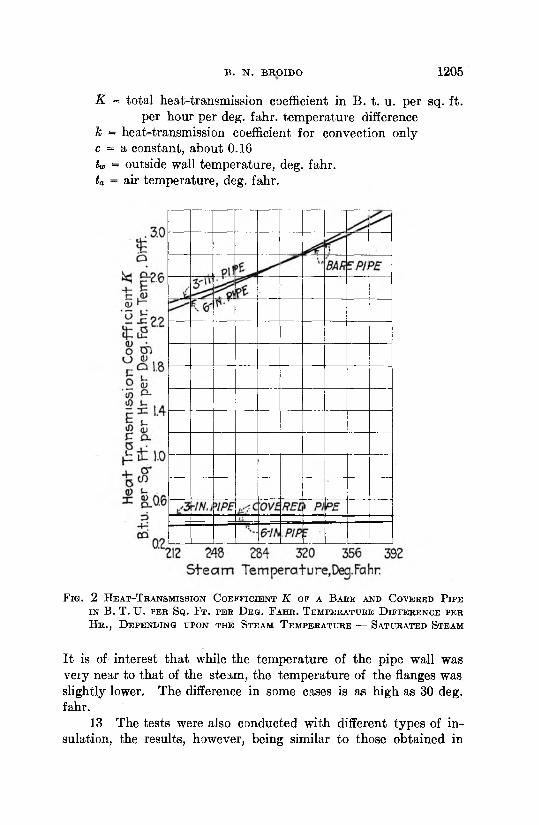
K = total heat-transmission coefficient in B. t. u. per sq. ft.per hour per deg. fahr. temperature difference
Jc = heat-transmission coefficient for convection only c = a constant, about 0.16 tw = outside wall temperature, deg. fahr. ta = air temperature, deg. fahr.
F ig . 2 H e a t - T r a n s m is s io n C o e f f i c i e n t K ok a B a b e a n d C o v e r e d P ip e i n B . T . U . p e r S q . F t . p e r D e g . F a h r . T e m p e r a t u r e D i f f e r e n c e p e r H r . , D e p e n d in g u p o n t h e S te a m T e m p e r a t u r e — S a t u r a t e d S te a m
It is of interest that while the temperature of the pipe wall was very near to that of the steam, the temperature of the flanges was slightly lower. The difference in some cases is as high as 30 deg. fahr.
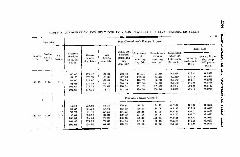
13 The tests were also conducted with different types of insulation, the results, however, being similar to those obtained in
like tests in this country. Table 2 shows results of experiments conducted with a covering consisting of 2-in.-thick shells of a porous burned material similar to kieselguhr, wrapped with canvas and painted twice with asphalt varnish.
14 Fig. 2 shows also the coefficient of heat transmission of the covered pipes.
15 Tests to determine the heat loss by transmission of superheated steam can be carried out only with steam that is flowing. The heat content of steam, both at the inlet and outlet of the pipe, must be determined, and the difference multiplied by the amount
1206 H IG H -TE M PER A TU R E AND H IG H -PR E SSU R E STEAM L IN E S
TA B LE 3 C O E F F IC IE N T S OF H E A T -T R A N SM ISS IO N FO R BA RE A ND COVERED P IP E S A T VARIOUS STEAM T E M P E R A T U R E S A N D SAVINGS R E SU L T IN G F R O M C O V E R IN G P IP E — SA TU R A TED STEAM
Final steam, tem p.,
deg. fahr.
3-in. Line 6-in. Line
KSaving
th rough covering, per cent
KSaving
through covering, per cent
Barepipe,B .t.u .
Coveredpipe,B .t.u .
Barepipe,B .t.u .
Coveredpipe,B .t.u .
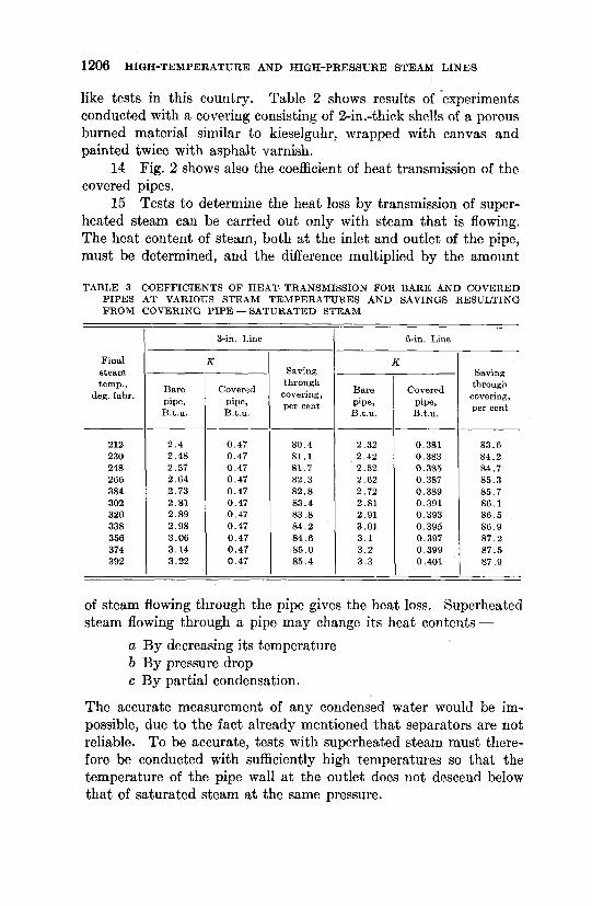
212 2 .4 0 .47 80.4 2.32 0.381 83.6230 2.48 0 .47 81.1 2 .42 0.383 84.2248 2.57 0 .47 81.7 2.52 0.385 84.7266 2.64 0 .47 82.3 2.62 0.387 85.3384 2.73 0 .47 82.8 2 .72 0.389 85.7302 2 .81 0.47 83.4 2.81 0.391 86.1320 2 .89 0.47 83.8 2.91 0.393 86 .5338 2 .98 0 .47 84.2 3.01 0.395 86.9356 3.06 0.47 84 .6 3 .1 0.397 87 .2374 3 .14 0.47 85 .0 3 .2 0 .399 87 .5392 3 .22 0.47 85 .4 3 .3 0.401 87 .9
of steam flowing through the pipe gives the heat loss. Superheated steam flowing through a pipe may change its heat contents —
a By decreasing its temperature b By pressure drop c By partial condensation.
The accurate measurement of any condensed water would be impossible, due to the fact already mentioned that separators are not reliable. To be accurate, tests with superheated steam must therefore be conducted with sufficiently high temperatures so that the temperature of the pipe wall at the outlet does not descend below that of saturated steam at the same pressure.
B . N . B R qiD O 1207
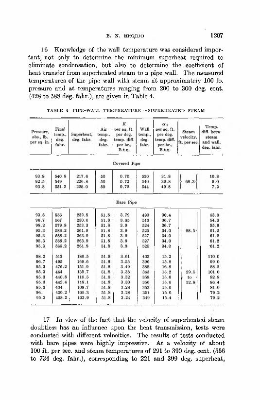
16 Knowledge of the wall temperature was considered important, not only to determine the minimum superheat required to eliminate condensation, but also to determine the coefficient of heat transfer from superheated steam to a pipe wall. The measured temperatures of the pipe wall with steam at approximately 100 lb. pressure and at temperatures ranging from 200 to 300 deg. cent. (428 to 588 deg. fahr.), are given in Table 4.
TABLE 4 P IP E -W A L L T E M P E R A T U R E — S U PE R H E A T E D STEA M
17 In view of the fact that the velocity of superheated steam doubtless has an influence upon the heat transmission, tests were conducted with different velocities. The results of tests conducted with bare pipes were highly impressive. At a velocity of about 100 ft. per sec. and steam temperatures of 291 to 390 deg. cent. (556 to 734 deg. fahr.), corresponding to 221 and 399 deg. superheat,
1208 H IG H -TE M PER A TU R E AND H IG H -PR E SSU R E STEAM L IN E S
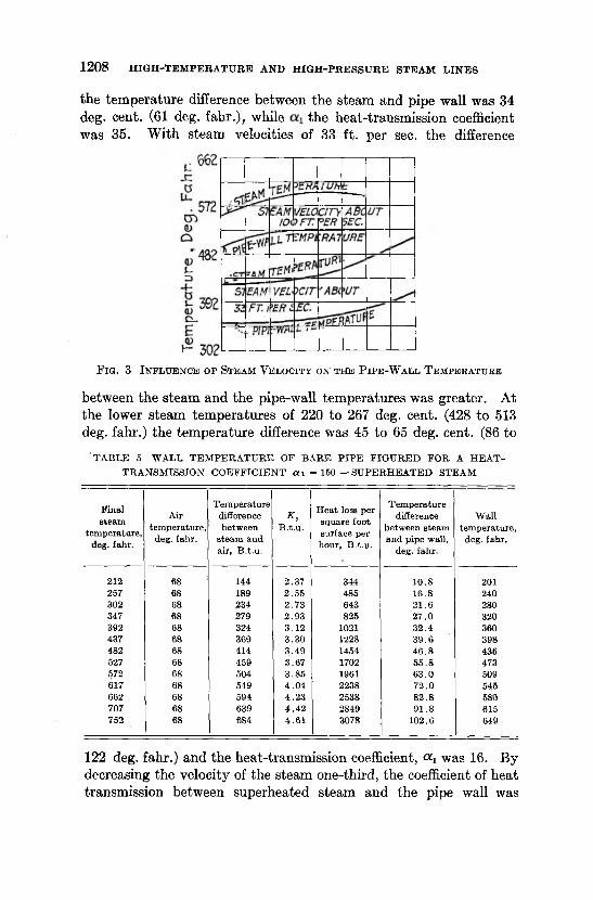
the temperature difference between the steam and pipe wall was 34 deg. cent. (61 deg. fahr.), while the heat-transmission coefficient was 35. With steam velocities of 33 ft. per sec. the difference
F ig . 3 I n f l u e n c e o f St e a m V e l o c it y o n t h e P ip e -W a l l T e m p e r a t u r e
between the steam and the pipe-wall temperatures was greater. At the lower steam temperatures of 220 to 267 deg. cent. (428 to 513 deg. fahr.) the temperature difference was 45 to 65 deg. cent. (86 to
T A B LE 5 W ALL T E M P E R A T U R E OF B A RE P IP E F IG U R E D FO R A H E A T - TR A N SM ISSIO N C O E F F IC IE N T ou = 150 — S U PE R H E A T E D STEAM
Final steam
tem perature, deg. fahr.
Air tem perature,
deg. fahr.
Tem perature difference between
steam and air, B .t.u .
K,B.t.u .
H eat loss per square foot surface per hour, B .t.u .
Tem perature difference
between steam and pipe w all,
deg. fahr.
W all tem perature,
deg. fahr.
212 68 144 2.37 344 10.8 201257 68 189 2.55 485 16.8 240302 68 234 2.73 643 21.6 280347 68 279 2 .93 825 27 .0 320392 68 324 3-12 1021 32.4 360437 68 369 3 .30 1228 39 .6 398482 68 414 3.49 1454 46 .8 436527 68 459 3.67 1702 55.8 473572 68 504 3.85 1961 63.0 509617 68 549 4.04 2238 72.0 545662 68 594 4 .23 2538 82.8 580707 68 639 4 .42 2849 91.8 615752 68 684 4.61 3078 102.6 649
122 deg. fahr.) and the heat-transmission coefficient, « i was 16. By decreasing the velocity of the steam one-third, the coefficient of heat transmission between superheated steam and the pipe wall was
B . N . BROIDO 1209
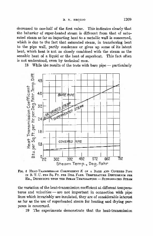
decreased to one-half of the first value. This indicates clearly that the behavior of super-heated steam is different from that of saturated steam as far as imparting heat to a metallic wall is concerned, which is due to the fact that saturated steam, in transferring heat to the pipe wall, partly condenses or gives up some of its latent heat, which heat is not as closely combined with the steam as the sensible heat of a liquid or the heat of superheat. This fact often is not understood, even by technical men.
18 While the results of the tests with bare pipe — particularly
F ig . 4 H e a t - T b a n s m is s io n .C o e f f i c i e n t K o f a B a b e a n d C o v e b e d P ip e i n B . T . U . p e e S q . F t . p e e D e g . F a h b . T e m p e e a tu b e D i f f e b e n c e p e e H b ., D e p e n d in g u p o n t h e S te a m T e m p e e a tu b e — S u p e r h e a t e d S te a m
the variation of the heat-transmission coefficient at different temperatures and velocities — are not important in connection with pipe lines which invariably are insulated, they are of considerable interest as far as the use of superheated steam for heating and drying purposes is concerned.
19 The experiments demonstrate that the heat-transmission
1210 H IG H -TE M PER A TU R E AND H IG H -PR E S S U R E STEAM L IN E S
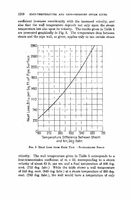
coefficient increases considerably with the increased velocity, and also that the wall temperature depends not only upon the steam temperature but also upon its velocity. The results given in Table 4 are presented graphically in Fig. 3. The temperature drop between steam and the pipe wall, as given, applies only to one certain steam
and Air, Deg Fahr.F ig . 5 H e a t L o ss fr o m B a r e P ip e — S u p e r h e a t e d Stea m
velocity. The wall temperature given in Table 5 corresponds to a heat-transmission coefficient of = 32, corresponding to a steam velocity of about 83 ft. per sec. and a final temperature of 400 deg. cent. (752 deg. fahr.) While the table shows a wall temperature of 343 deg. cent. (649 deg. fahr.) at a steam temperature of 400 deg. cent. (752 deg. fahr.), the wall would have a temperature of only
B . N . BROIDO 1211
314 deg. cent. (597 deg. fahr.) at a heat-transmission coefficient cci of 20.
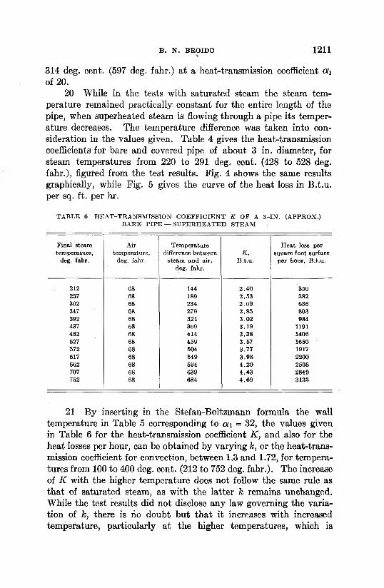
20 While in the tests with saturated steam the steam temperature remained practically constant for the entire length of the pipe, when superheated steam is flowing through a pipe its temperature decreases. The temperature difference was taken into consideration in the values given. Table 4 gives the heat-transmission coefficients for bare and covered pipe of about 3 in. diameter, for steam temperatures from 220 to 291 deg. cent. (428 to 528 deg. fahr.), figured from the test results. Fig. 4 shows the same results graphically, while Fig. 5 gives the curve of the heat loss in B.t.u. per sq. ft. per hr.
TABLE 6 H EA T -TR A N SM ISSIO N C O E F F IC IE N T K O F A 3 -IN . (A PPRO X .) BA RE P IP E — SU PE R H E A T E D STEAM
Final steam tem perature,
deg. fahr.
Air tem perature,
deg. fahr.
Tem perature difference between
steam and air, deg. fahr.
K , B .t.u .
H eat loss per square foot surface
per hour, B .t.u .
212 68 144 2.40 350257 68 189 2 .53 382302 68 234 2.69 636347 1 68 279 2 .85 803392 68 324 3 .02 984437 68 369 3 .19 1191482 68 414 3 .38 1406527 68 459 3.57 1650572 68 504 3.77 1917617 68 549 3 .98 2200662 68 594 4 .20 2505707 68 639 4 .43 2849752 68 684 4 .69 3133
21 By inserting in the Stefan-Boltzmann formula the wall temperature in Table 5 corresponding to a i = 32, the values given in Table 6 for the heat-transmission coefficient K , and also for the heat losses per hour, can be obtained by varying k, or the heat-transmission coefficient for convection, between 1.3 and 1.72, for temperatures from 100 to 400 deg. cent. (212 to 752 deg. fahr.). The increase of K with the higher temperature does not follow the same rule as that of saturated steam, as with the latter k remains unchanged. While the test results did not disclose any law governing the variation of k, there is no doubt but that it increases with increased temperature, particularly at the higher temperatures, which is
1212 H IG H -TE M PER A TU R E AND H IG H -PR E S S U R E STEAM L IN E S
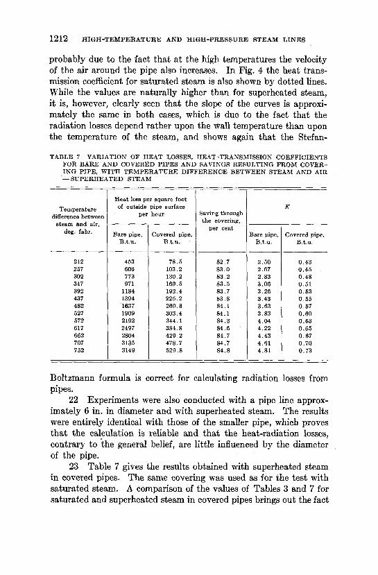
probably due to the fact that at the high temperatures the velocity of the air around the pipe also increases. In Fig. 4 the heat transmission coefficient for saturated steam is also shown by dotted lines. While the values are naturally higher than for superheated steam, it is, however, clearly seen that the slope of the curves is approximately the same in both cases, which is due to the fact that the radiation losses depend rather upon the Wall temperature than upon the temperature of the steam, and shows again that the Stefan-
TA B LE 7 V A RIA TIO N O F H E A T LOSSES, H E A T -T R A N SM ISS lO N C O E FF IC IE N T S FO R B A R E A N D CO VERED P IP E S AN D SAVINGS R E SU L T IN G FRO M COVERIN G P IP E , W IT H T E M P E R A T U R E D IF F E R E N C E B E T W E E N STEAM A ND A IR — SU PE R H E A T E D STEAM
Tem perature difference between
steam and air, deg. fahr.
H e a t loss per square foot of outside pipe surface
per hour Saving through the covering,
per cent
K
Bare pipe, B .t.u .
Covered pipe, B .t.u .
Bare pipe, B .t.u .
Covered pipe, B .t.u .
212 453 78 .5 82.7 2.50 0.43257 606 103.2 83 .0 2.67 0 .45302 773 130.2 83 .2 2.83 0 .48347 971 160.5 83.5 3 .06 0.51392 1184 192.4 83 .7 3.26 0.53437 1394 225.2 83 .8 3.43 0 .55482 1637 260.8 84.1 3.63 0 .57527 1909 303.4 84.1 3 .83 0.60572 2192 344.1 84.3 4.04 0 .63617 2497 384.8 84 .6 4 .22 0 .65662 2804 429.2 84.7 4.43 0 .67707 3135 478.7 84.7 4 .61 0 .70752 3149 529.8 84.8 4.81 0.73
Boltzmann formula is correct for calculating radiation losses from pipes.
22 Experiments were also conducted with a pipe line approximately 6 in. in diameter and with superheated steam. The results were entirely identical with those of the smaller pipe, which proves that the calculation is reliable and that the heat-radiation losses, contrary to the general belief, are little influenced by the diameter of the pipe.
23 Table 7 gives the results obtained with superheated steam in covered pipes. The same covering was used as for the test with saturated steam. A comparison of the values of Tables 3 and 7 for saturated and superheated steam in covered pipes brings out the fact
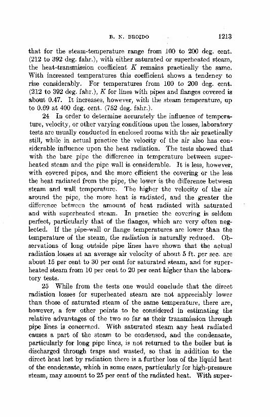
B . N . BROJDO 1213
that for the steam-temperature range from 100 to 200 deg. cent. (212 to 392 deg. fahr.), with either saturated or superheated steam, the heat-transmission coefficient K remains practically the same. With increased temperatures this coefficient shows a tendency to rise considerably. For temperatures from 100 to 200 deg. cent. (212 to 392 deg. fahr.), K for lines with pipes and flanges covered is about 0.47. It increases, however, with the steam temperature, up to 0.69 at 400 deg. cent. (752 deg. fahr.).
24 In order to determine accurately the influence of temperature, velocity, or other varying conditions upon the losses, laboratory tests are usually conducted in enclosed rooms with the air practically still, while in actual practice the velocity of the air also has considerable influence upon the heat radiation. The tests showed that with the bare pipe the difference in temperature between superheated steam and the pipe wall is considerable. It is less, however, with covered pipes, and the more efficient the covering or the less the heat radiated from the pipe, the lower is the difference between steam and wall temperature. The higher the velocity of the air around the pipe, the more heat is radiated, and the greater the difference between the amount of heat radiated with saturated and with superheated steam. In practice the covering is seldom perfect, particularly that of the flanges, which are very often neglected. If the pipe-wall or flange temperatures are lower than the temperature of the steam, the radiation is naturally reduced. Observations of long outside pipe lines have shown that the actual radiation losses at an average air velocity of about 5 ft. per sec. are about 15 per cent to 30 per cent for saturated steam, and for superheated steam from 10 per cent to 20 per cent higher than the laboratory tests.
25 While from the tests one would conclude that the direct radiation losses for superheated steam are not appreciably lower than those of saturated steam of the same temperature, there are, however, a few other points to be considered in estimating the relative advantages of the two so far as their transmission through pipe lines is concerned. With saturated steam any heat radiated causes a part of the steam to be condensed, and the condensate, particularly for long pipe lines, is not returned to the boiler but is discharged through traps and wasted, so that in addition to the direct heat lost by radiation there is a further loss of the liquid heat of the condensate, which in some cases, particularly for high-pressure steam, may amount to 25 per cent of the radiated heat. With super
1214 H IG H -TE M PER A TU R E AND H IG H -PR ESSTJRE STEAM L IN E S
heated steam the heat lost only decreases the temperature and no condensation occurs as long as the steam remains superheated, so that no additional heat besides that radiated is wasted.
26 Another important fact to be considered in connection with superheated steam is that a considerably higher velocity in the pipe lines is permissible. The velocity of the steam in a pipe, or the size of the pipe, is usually determined by the maximum friction loss or pressure drop which can be allowed.
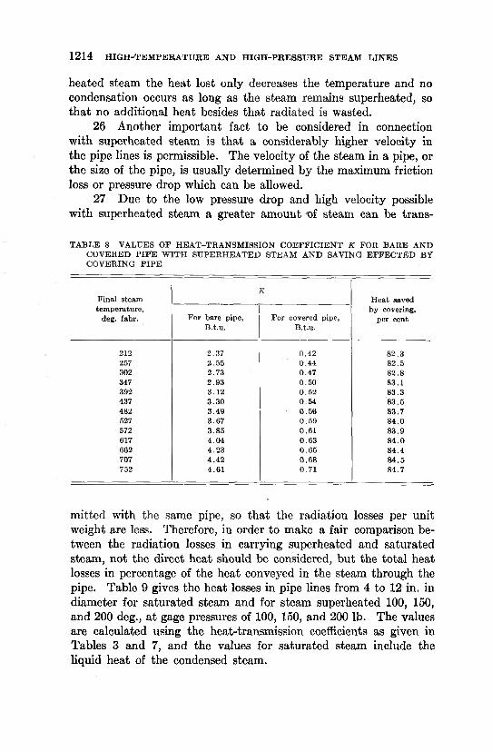
27 Due to the low pressure drop and high velocity possible with superheated steam a greater amount of steam can be trans-
T A B LE 8 VALUES O F H E A T -T R A N SM ISS IO N C O E F F IC IE N T K FO R B A RE A ND CO V E R ED P IP E W IT H SU PE R H E A T E D STEA M A N D SAVING E F F E C T E D BY C O V ER IN G P IP E
Final steam tem perature,
deg. fahr. For bare pipe, B .t.u.
K
For covered pipe, B .t.u.
H eat saved by covering,
per cent
212 2.37 0.42 82.3257 2 .55 0 .44 82.5302 2.73 0.47 82.8347 2.93 0.50 83.1392 3.12 0.52 83.3437 3 .30 0.54 83.5482 3.49 • 0 .56 83.7527 3.67 0.59 84.0572 3.85 0.61 83.9617 4 .04 0 .63 84 .0662 4 .23 0 .65 84.4707 4.42 0.68 84 .5752 4.61 0.71 84.7
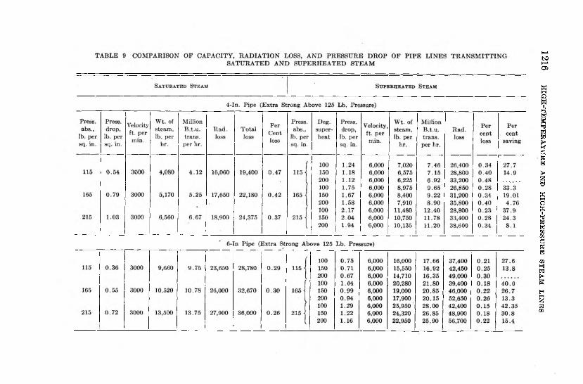
mitted with the same pipe, so that the radiation losses per unit weight are less. Therefore, in order to make a fair comparison between the radiation losses in carrying superheated and saturated steam, not the direct heat should be considered, but the total heat losses in percentage of the heat conveyed in the steam through the pipe. Table 9 gives the heat losses in pipe lines from 4 to 12 in. in diameter for saturated steam and for steam superheated 100, 150, and 200 deg., at gage pressures of 100, 150, and 200 lb. The values are calculated using the heat-transmission coefficients as given in Tables 3 and 7, and the values for saturated steam include the liquid heat of the condensed steam.
B . N . B K O ID O%
1215
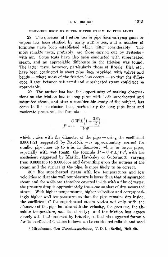
28 The question of friction loss in pipe lines carrying gases or vapors has been studied by many authorities, and a number of formulas have been established which differ considerably. The most reliable tests, probably, are those carried out by Fritsche 1 with air. Some tests have also been conducted with superheated steam, and no appreciable difference in the friction was found. The latter tests, however, particularly those of Eberle, Biel, etc., have been conducted in short pipe lines provided with valves and bends — where most of the friction loss occurs — so that the difference, if any, between saturated and superheated steam could not be appreciable.
29 The author has had the opportunity of making observations on the friction loss in long pipes with both superheated and saturated steam, and after a considerable study of the subject, has come to the conclusion that, particularly for long pipe lines and moderate pressures, the formula —
PR E SSU R E DROP O F SU PER H EA T ED STEAM IN P IP E L IN E S
which varies with the diameter of the pipe — using the coefficient 0.0001321 suggested by Babcock — is approximately correct for smaller pipe lines up to 4 in. in diameter; while for larger pipes, especially with wet steam, the formula P - CW2L / V d b, with the coefficient suggested by Martin, Hawksley or Gutermuth, varying from 0.0003135 to 0.0003557 and depending upon the wetness of the steam and the surface of the pipe, is more likely to be correct.
30 * For superheated steam with low temperatures and low velocities so that the wall temperature is lower than that of saturated steam and the walls are therefore covered inside with a film of water, the pressure drop is approximately the same as that of dry saturated steam. With higher temperatures, higher velocities and correspondingly higher wall temperatures so that the pipe remains dry inside, the coefficient C for superheated steam varies not only with the diameter of the pipe but also with the velocity, the pressure, the absolute temperature, and the density; and the friction loss agrees closely with that observed by Fritsche, so that his suggested formula for the coefficient C which follows can be considered reliable and used
1 Mitteilungen iiber Forschungsarbeiten, V. D. I. (Berlin), Heft 60.
1216 H
IGH
-TEMPER
ATU
RE
AND H
IGH
-PRESSU
RE
STEAM
LIN
ES
B.
N.
BR
OID
O
1217
1218 H IG H -TE M PER A TU R E AND H IG H -PR E SSU R E STEAM L IN E S
safely in calculating the pressure drop for long pipe lines carrying superheated steam and moderate pressures:
C = 0.0000022 (tf/144)0'148 (T /pw ) 0MSd “ 0/209where —
T = absolute temperature, deg. fahr. p = absolute pressure, lb. per sq. in. w = velocity, ft. per sec. d = pipe diameter, ft.R = 85.7 for steam.
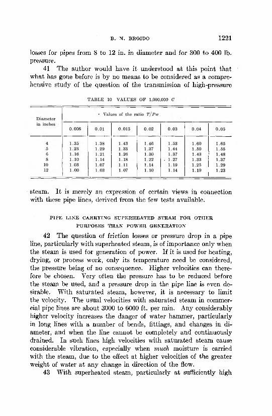
In order to facilitate the use of this formula a table was calculated giving for air (R = 53.34) the values of 1,000,000 C corresponding to values of the ratio T /pw for pipe diameters ranging from 1 in. to48 in. This table is. given in Marks’ Mechanical Engineers’ Handbook. When used for steam its values must be increased by 7 per cent on account of the different value of R used.
31 Of all the problems involved in connection with the use of high-pressure steam the question of its transmission has apparently been given the least attention. A great number of tests have been conducted to determine the friction losses in pipe lines carrying various fluids, such as water, air, and steam of moderate pressures, which tests were used to establish a number of formulas showing the interrelation of the friction losses, the density and velocity of the fluid, and the shape and roughness of the conductor, etc. The accuracy of these formulas, however, is limited to the range for which they were established. Outside of this range their use is frequently misleading.
32 As far as the author knows, all formulas for determining pressure drop, particularly for steam, are based on tests where the pressures in no case exceeded 300 lb. per sq. in. For higher pressures they should be used with caution. In his extensive study of this subject and search for a formula which would cover all conditions, B ie l1 found that the pressure drop caused by the resistance to flow of any fluid, for the same diameter of pipe, the same length, same temperature, and the same constant R, can be expressed by the equation Pd = CWnpm, in which the values of the exponents are n = 1.852, m = 0.852. Approximately the same values were found by Brabble,2 who made extensive tests, particularly to determine
1 Mitteilungen tiber Forschungsarbeiten, Heft 44.2 Zeitschrift des Vereines deutscher Ingenieure, 1916.
B . N . BROJDO 1219
the resistance, in pipe lines, of high and low pressure, water and air heating. He found, however, that the exponents vary with the roughness of the pipe. For steel pipe his exponent is 0.853.
33 The question arises as to how far the known formulas for the resistance of flow are applicable to high-pressure and high- temperature steam. The most elaborate tests ever undertaken with high-pressure steam for prime movers were carried out by Dr. Wilhelm Schmidt,1 and extended over a number of years. The pipe lines, however, were too small (only about 4 in. in diameter) and too short to establish new formulas or even to verify those already existing for pressure drop in pipe lines.
34 The high-pressure steam plant of a chemical company in Griesheim, Germany, was found to be more suitable for the purpose. This plant consisted of two 500-hp. boilers of the Stirling type, built for a pressure of 30 atmospheres (440 lb. per sq. in.). While carrying out tests on the boiler the author had the opportunity to observe the pressure losses in the pipe line which was about 150 mm. (approximately 6 in.) in diameter and 380 ft. long. Tests with different pressures and velocities have shown that the variations of pressure drop at different velocities and initial pressures are smaller than would be expected if the foregoing formulas were correct also for very high pressures. The exponents obtained were smaller than those given above in the preceding paragraph. It is therefore the opinion of the author that the pressure drop in straight lines carrying superheated steam of 300 to 600 lb. pressure is from 10 per cent to 25 per cent less than that calculated by the use of the existing formulas for moderate pressures.
35 A comparison of the results of tests made at pressures between 250 and 440 lb. with those obtained by using the Fritsche formula bears out this statement. The pressure drop in fittings and bends was carefully determined by mercury U-tubes, and the resistance to the flow, which is usually expressed in lengths of straight pipe, was considerably higher than formerly supposed. As compared with the formula of Conrad Meier, given in the paper of D . E, Foster,2 the values obtained were from 20 per cent to 35 per cent higher.
36 The foregoing would tend to show that most of the pressure drop in pipe lines takes place in the bends, fittings, and valves
1 Zeitschrift des Vereines deutscher Ingenieure, 1921.1 Effect of Fittings on Flow of Fluids through Pipe Lines, Trans. Am.
Soc. M. E ., vol. 42, p. 647.
1220 H IG H -TE M PER A TU R E AND H IG H -PR E SSU R E STEAM L IN E S
especially the latter, rather than in the straight pipes. In particular, sudden restriction of area and change in direction of flow affect the pressure of the steam. This has been verified by careful tests even with moderate pressures. The author recently had the opportunity to observe pressure differences in pipe lines in connection with superheaters, and an appreciable amount of pressure drop which was attributed to the superheater was found to occur in the non-return valves, the orifice of the flowmeter, etc., while the pressure drop in the superheater itself, which consisted of long, straight pipes without any area restriction, was very low as compared with the pressure drop through the fittings.
B E ST V ELOCITY O F STEAM FLO W FO R U SE IN H IG H -PR ESSU R E
L IN E S
37 It is therefore apparent that in pipe lines carrying high- pressure steam, provided they consist of long, straight pipe sections, high velocities are permissible, and for high pressures — say, from 300 to 500 lb. — 10,000 to 12,000 ft. per min. seems to be the most advisable for lines over 5 in. in diameter and with a continuous steam flow, as, for instance, when the steam is used in turbines. With reciprocating engines, naturally, lower velocities are to be chosen, depending upon the length of the line, the percentage of cut-off, and the number of revolutions of the engine. For high- pressure reciprocating engines located at a considerable distance from the steam generator it was found advisable to make that portion of the steam line near the engine of a larger diameter in order to minimize the fluctuation of the steam flow due to the intermittent steam demands of the engine, and to allow higher velocities by means of a correspondingly smaller pipe diameter, near the boiler.
38 If a line carrying high-pressure steam contains a number of bends, fittings, and valves, lower velocities than those just mentioned should be employed if excessive pressure drop is to be avoided.
39 The higher cost of the larger sizes necessitated by lower velocities, and the strength of the material required for higher pressures, are factors to be taken in consideration in determining the size of the line.
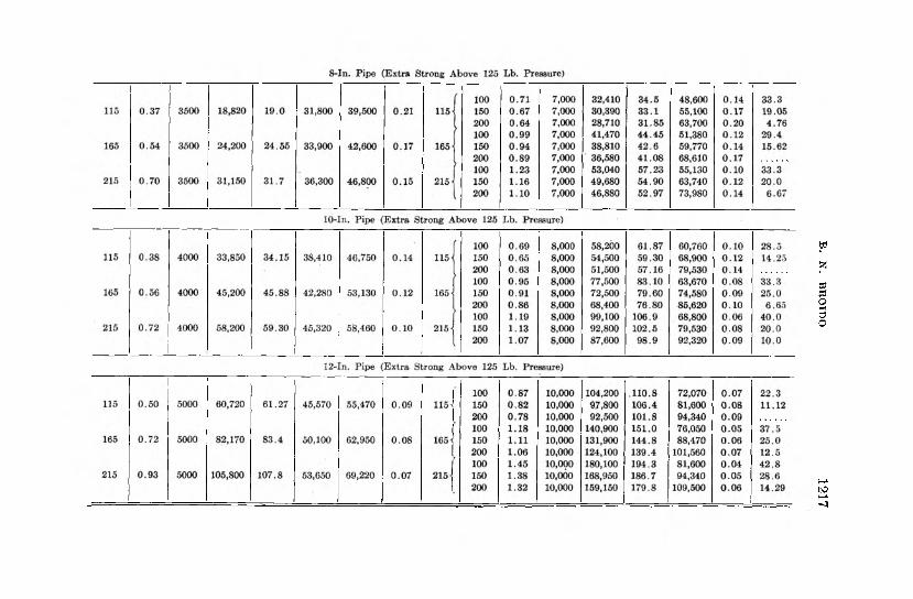
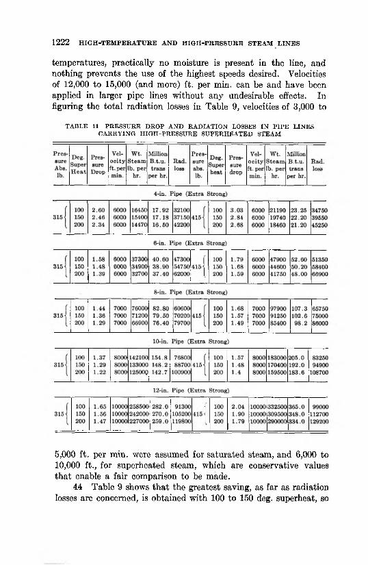
40 The table mentioned in Par. 30 giving values of 1,000,000 C is intended only for low pressures. Table 10 has therefore been devised to give values of the same quantity for pressures up to 600 lb. and any superheat. Table 11 gives the pressure drop and radiation
B . N . BKQIDO 1221
losses for pipes from 8 to 12 in. in diameter and for 300 to 400 lb. pressure.
41 The author would have it understood at this point that what has gone before is by no means to be considered as a comprehensive study of the question of the transmission of high-pressure
steam. It is merely an expression of certain views in connection with these pipe lines, derived from the few tests available.
P I P E L IN E C A R R Y IN G S U P E R H E A T E D ST E A M F O R O T H E R
P U R P O S E S T H A N P O W E R G E N E R A T IO N
42 The question of friction losses or pressure drop in a pipe line, particularly with superheated steam, is of importance only when the steam is used for generation of power. If it is used for heating, drying, or process work, only its temperature need be considered, the pressure being of no consequence. Higher velocities can therefore be chosen. Very often the pressure has to be reduced before the steam be used, and a pressure drop in the pipe line is even desirable. With saturated steam, however, it is necessary to limit the velocity. The usual velocities with saturated steam in commercial pipe lines are about 3000 to 6000 ft. per min. Any considerably higher velocity increases the danger of water hammer, particularly in long lines with a number of bends, fittings, and changes in diameter, and when the line cannot be completely and continuously drained. In such lines high velocities with saturated steam cause considerable vibration, especially when much moisture is carried with the steam, due to the effect at higher velocities of the greater weight of water at any change in direction of the flow.
43 With superheated steam, particularly at sufficiently high
1222 H IG H -TE M PER A TU R E AND H IG H -PR E S S U R E STEAM L IN E S
temperatures, practically no moisture is present in the line, and nothing prevents the use of the highest speeds desired. Velocities of 12,000 to 15,000 (and more) ft. per min. can be and have been applied in larger pipe lines without any undesirable effects. In figuring the total radiation losses in Table 9, velocities of 3,000 to
TA BLE 11 PR E S SU R E D R O P A N D R A D IA T IO N LOSSES IN P IP E L IN E S CA R R Y IN G H IG H -P R E S S U R E SU PE R H E A T E D STEAM
5.000 ft. per min. were assumed for saturated steam, and 6,000 to10.000 ft., for superheated steam, which are conservative values that enable a fair comparison to be made.
44 Table 9 shows that the greatest saving, as far as radiation losses are concerned, is obtained with 100 to 150 deg. superheat, so
B . N . BROIDO 1223
that when the steam is superheated only for the purpose of elimination of condensation or reduction of radiation, a moderate superheat of 100 to 150 deg., depending upon the length of the line, is sufficient. It does not mean, however, that moderate superheat is in general more desirable. If the steam is used for power purposes, the advantages of high superheat in the prime mover will more than overbalance the slightly higher radiation losses.
45 A remarkable feature is the very slight increase of pressure drop, which throughout the whole range of the table, with one exception, does not exceed 1 lb. for 100 ft. of pipe length, in spite of the fact that the velocity was doubled. The lower density of superheated steam, the absence of moisture, the dry pipe walls, and the reduced amount of foreign matter — the greatest part of which is usually left in the superheater — account for the low pressure drop.
46 It is commonly believed that even with superheated steam the pipe walls are covered on the inside with a film of moisture. This is true for low superheat with low steam velocities. At higher superheat and high velocities, however, the wall attains a temperature higher than that of saturated steam, and remains dry. The author has made a study of the wall temperatures of apparatus carrying steam, particularly in connection with the use of superheated steam in radiators for drying or heating purposes, where it is of considerable importance, whether the inside surface is dry or wet. This, however, may be made the subject of a separate paper at a future meeting.
EX A M PLE SH O W IN G ADVANTAGES O F U SIN G H IG H E R V E LO C IT IE S
W IT H SU PER H EA T ED STEAM
47 The three following examples from actual practice demonstrate how the possibility of applying higher velocities with superheated steam may be advantageously utilized in reducing the radiation losses and the cost of the piping and covering.
48 The management of a large textile concern, realizing that it was necessary to lower their power cost, decided as one means to this end to avail themselves of the advantages of superheated steam. Each of the five boilers in the plant was accordingly equipped with superheaters for 200 deg. superheat.
49 The steam was for use in two engines, one triple expansion and one compound. The compound engine was located about 950 ft. from the boiler house. The piping between boiler and engine
1224 H IG H -TE M PER A TU R E AND H IG H -PR E S S U R E STEAM LIN ES
was entirely changed, the old 8-in. piping, being replaced by a new 6-in. lina. With the old piping and saturated steam the average pressure drop in the line between boiler and engine was 6 lb. With the new line and superheated steam it was 7.5 lb. The comparatively low pressure drop in the new line was mainly due to the appreciably decreased steam consumption of the engine. The radiation loss of the 8-in. line would naturally be 33 per cent higher than that of the 6-in. line for the same steam temperature.
50 A chemical company manufacturing aniline dyes had an 8-in. pipe line, 1400 ft. long, in their plant, conveying steam from their boiler room to the process house. An increase in production required the approximate doubling of the steam consumption in the power house, and a second pipe line accordingly was planned. At the same time the use of higher temperatures was found advisable, since the boiler pressure could not be increased appreciably. Superheaters were installed in the boilers, and approximately double the amount of steam superheated was sent through the pipe. Pressure drop was of no consequence, while the radiation loss per pound of steam conveyed was decreased 36 per cent.
51' A heating plant had two mains 10 in. and 8 in. in diameter and 2300 ft. long. The 10-in. line was used in the cold winter months, while the smaller one was utilized during the remainder of the year. With saturated steam the larger steam demand in the winter months could not be supplied with the small pipe alone, due to the danger of water hammer and excessive vibration, and the larger pipe had to be used. In order to have dry steam at the end of the line, and avoid the losses in liquid heat of the steam condensed in the line, superheaters were installed, and it was found that the greater amount of steam could be conveyed through the smaller pipe without any difficulty. The radiation loss, as compared with the 10-in. line, was 20 per cent less.
SU M M A R Y
52 To summarize:a The heat-radiation losses in B.t.u. per square foot of surface
of an uncovered pipe carrying saturated steam are independent of the velocity of the steam.
b The temperature of the pipe wall is slightly lower than that of the saturated steam in a bare pipe, and approaches close to that temperature in a covered pipe.
B . N . BRQIDO 1225
c The velocity of superheated steam has considerable influence upon the heat loss by radiation of a bare pipe.
d The temperature of the pipe wall of a bare pipe carrying superheated steam is appreciably lower than that of the steam. The higher the temperature and the lower the velocity of the steam, the greater is the difference. With a covered pipe the difference is considerably less, and the more efficient the insulation, the smaller this difference.
e The heat-transmission coefficient between saturated steam and a pipe wall is approximately 400, and varies slightly only with the temperature difference between the steam and the outside air.
/ With superheated steam the coefficient a.i depends largely upon the velocity of steam. It was found to be about 32 at a steam velocity of 83 ft. per sec. and a steam temperature of approximately 750 deg. fahr., and to decrease rapidly with decreased velocity. Whether the pipe is dry or covered with a film of moisture also influences the heat-transmission coefficient.
g The coefficient of heat transmission from steam — either saturated or superheated — to the surrounding air remains practically constant up to a temperature of about 350 deg. fahr. and tends to increase at higher temperatures.
h When superheated steam is flowing through a pipe at a sufficiently high velocity and temperature so that the pipe remains dry inside, the friction loss is considerably less than with saturated steam of the same density and with the same velocity. With superheated steam higher velocities and smaller pipe sizes can therefore be chosgn, also appreciably decreasing the radiation loss as well as the cost of the pipe line and covering.
i The values of the pressure drop in straight pipes, obtained by using existing formulas seem to be too high for pressures above 300 lb., and the error apparently increases with higher pressures.
j The known values of the lengths of pipes in whioh the resistance to the steam flow is equal to those of fittings or valves, are apparently too small for high-pressure steam, particularly with respect to valves.
k If superheated steam is used for other purposes than for power, and pressure drop is of no consequence, it can be conveyed in pipes at a very high velocity, as the danger from water hammer and vibration is eliminated.
1226 H IG H -TE M PER A TU R E AND H IG H -PR E SSU R E STEAM L IN E S
DISCUSSION
E. G. B a i l e y . The factors considered in the design of steam lines have usually been limited to the cost of pipe and covering, the pressure loss, and the radiation loss. Proper conditions for the installation of steam meters should also receive due consideration.
The steam meter has now become such an integral part of the plant equipment for measuring the output of boilers, steam consumption of turbines and various units as well as the steam distribution, that the conditions suitable for the installation of such meters should be considered in the design of piping. This applies not only to the selection of the proper size of pipe but also to the layout for flow conditions as well as for proper expansion.
As a rule the piping is laid out with little or no consideration for meters and the meter manufacturer is later confronted with many difficult problems in finding a suitable location in which the primary element of a steam meter can be installed.
Practically all steam meters have a primary device such as the pitot tube, orifice, flow nozzle or venturi tube that is placed in the line to obtain a differential pressure. The most used primary devices for steam are the orifice and flow nozzle, which are inserted between a pair of flanges and produce a small pressure loss in the steam line. It is natural that this pressure loss should be held at a minimum and most meters operate on approximately a two-pound differential pressure, part of which is restored so that the actual pressure loss is in the neighborhood of one pound.
The length of straight run of pipe required on the inlet and outlet side of such orifice or flow nozzle is a question that cannot be answered without knowing the nature of the pipe or fitting on the beginning of the straight run and also the steam velocity or rather the kinetic energy with which it flows through the pipe. Steam flowing through elbows, globe valves, angle valves, Y-fittings and tees has more disturbance than when it comes through a gate valve or around a long radius bend and, therefore, a longer straight run is required in order that the stream lines may be normal by the time they approach the primary metering device. On the other hand if the velocity of steam is low an orifice can be placed very close beyond fittings or bends.
The change in energy due to the differential pressure across the primary metering device should be definitely related to the total
D ISCU SSIO N 1227
kinetic energy of the steam as it approaches the primary device in order that the desired accuracy be obtained.
Meters can of course be designed to operate on a greater differential pressure so as to maintain the ratio of energy suitable for accuracy. However, there will be a greater pressure loss in the line than most engineers desire, and it, therefore, comes back to a matter of giving proper consideration to the value of steam meters and their requirements in laying out piping or at least the section of piping in which the meter is installed.
The maximum permissible velocity for any given design of steam meter and its primary device is represented by the formula
Velocity = FVSpecific Volume
where velocity is measured in feet per minute and F is a factor. This factor is not only dependent upon the meter construction but it also varies with the pipe design on either side of the orifice or primary device.
One meter manufacturer gives limiting velocities of Fmax = 8000\/sp. vol. and another Fmax = 10,500\/sp. vol. With steam at 250 lb. pressure and 200 deg. fahr. superheat having a specific volume of 2.35 the maximum velocities would be 12,240 and16,000 ft. per minute respectively.
These velocities are capable of being metered accurately only when the steam is flowing through straight pipe of reasonable length on either side of the primary device.
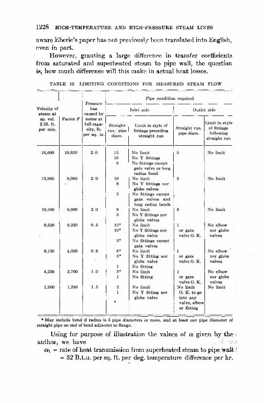
Table 12 gives an approximate idea of the factors for different lengths of straight pipe and the effect of fittings.
L. B. M c M i l l a n . The writer is in full agreement with the author regarding the merits of superheated steam in general, but feels that the author’s statements regarding relative rates of heat transmission from saturated and superheated steam to pipe walls are likely to be misinterpreted.
The author quotes the German investigator Eberle as authority for relatively low values of heat transmission from superheated steam to pipe wall, as compared with high values for saturated steam. It is a matter of common knowledge that heat is transmitted much more readily from saturated steam to a surface than from superheated steam. Eberle’s data have also been available and have been already referred to by most investigators on heat transfer during the past ten years, although so far as the writer is
aware Eberle’s paper has not previously been translated into English, even in part.
However, granting a large difference in transfer coefficients from saturated and superheated steam to pipe wall, the question is, how much difference will this make in actual heat losses.
1228 H IG H -TE M PER A TU R E AND H IG H -PR E SSU R E STEAM L IN E S
Using for purpose of illustration the values of a given by the i author, we have . ■.? ;.:v.
ol\ = rate of heat transmission from superheated steam to pipe walls i = 32 B.t.u. per sq. ft. per deg. temperature difference per hr.
D ISCUSSIO N 1229
«2 = rate of heat transmission from saturated steam to pipe wall = 400 B.t.u. per sq. ft. per deg. temperature difference per hr.
The value of a for saturated steam is thus over twelve times that for superheated steam and it would be only natural to expect that the loss from the saturated steam pipe would be far larger than that from a superheated steam pipe at the same temperature. Such would be the case if the transmission of heat from steam to pipe wall were the only factor involved, but the heat must be transmitted from the outside of the pipe to the air, or through insulation to the air. Therefore, the additional resistance to heat flow,is so great outside of the pipe that the difference in inside resistances becomes very small in comparison.
This is illustrated as follows:The inside surface resistance corresponding to cti = 32 is
i - 0.031
and the inside surface resistance corresponding to a-, = 400 is
4® ' ° - m S
. but for an efficiently insulated line a fair average resistance offered by the type and thickness of insulation ordinarily used on superheated steam lines in this country would be about 4.5. Therefore, the total resistances would be 4.5 + 0.031 = 4.531 for superheated line, and 4.5 + 0.0025 = 4.5025 for saturated steam line.
The actual heat losses are the reciprocals of these resistances,
or ̂ = 0.221 B.t.u. per sq. ft. per deg. temperature difference
per hr. for superheated steam line, and ̂gQ25 = ^-222 B.t.u. per
sq. ft. per deg. temperature difference per hr. for saturated steam line. Note that these differ by less than one per cent.In the case of bare pipes, there are larger differences, but even
with bare pipes the differences are of the order of only 10 per cent. These differences are of little importance as few bare pipes are used for the transmission of superheated steam.
Most published tables on heat losses from bare pipes are based on loss per square foot per degree temperature difference between pipe surface and air. These are therefore correct for the stated condition regardless of what is inside the pipe.
An analogy illustrating how a big difference in resistances may make little difference in flow is as follows:
Suppose we have two pipes of equal length, one 2 in. diameter and the other 6 in. diameter, and both connected to the same water main. But suppose also that each is bushed down to 1/8 in. and an equal length of 1/8-in. pipe is added to each. The resistance to flow in the 2-in. pipe is many times that in the 6-in., but the flow will be practically the same in both cases because in either case the resistance of the smaller pipe is so great that the resistance of the larger pipe is not sufficient to affect appreciably the total.
f ig . 4 illustrates how small are the differences in losses from superheated and saturated steam pipes. Even in the case of the bare pipes, the difference shown by this test is less than 5 per cent and on the insulated pipes the results from actual test showed a slightly lower average loss on saturated than on superheated steam pipes. This is the opposite of what one would expect, but in any case the difference one way or the other on insulated pipes is probably within the limits of experimental error and consequently not worthy of consideration.
In Par. 25, the author concludes “ that the direct radiation losses for superheated steam are not appreciably lower than for saturated steam at the same temperature,” and turns to other advantages of superheated steam.
This conclusion seems to be entirely in accordance with the facts, but in view of it one wonders why the author devotes the major portion of his paper to presenting Eberle’s data, apparently intended to show that there should be a considerable difference in losses and finally concludes that the difference is not appreciable.
Referring to Table 9 in which a lower radiation loss per pound of steam is shown for superheated steam than for saturated steam, this result is based entirely upon the assumption that the velocity in superheated steam lines is exactly double the velocity in saturated steam lines. This table shows higher actual heat losses on the superheated steam lines, but on the basis of the doubled velocity so much more steam is passed through the superheated steam line that the loss per pound is shown to be less. An explanation of just why the author assumed a doubled velocity in the superheated steam line instead of some other ratio would be necessary in order to give significance to this table.
In fact, it is the writer’s understanding that the practice of calculating steam line sizes on an assumed velocity is antiquated
1230 H IG H -TE M PER A TU R E AND H IG H -PR E S S U R E STEAM L IN E S
D ISCU SSIQ N 1231
and that the preferred method of calculating steam line sizes is based on allowable pressure drop.
The foregoing discussion is in no sense opposed to the use of superheated steam, but is intended to show the relative magnitudes of the factors which determine losses and to emphasize the fact that in a problem of this kind consideration of only one of the contributing factors does not lead to conclusive results.
L. L. B a r r e t t . Those engineers who have occasion to consider the heat losses from pipe lines conveying steam will be grateful to the author for his presentation of extracts from the paper of Chrs. Eberle.1 The author’s Figs. 1, 2, 3, 4, and 5 are identical with Eberle’s Figs. 22, 31, 35, 37, and 38 respectively, and the author’s Tables 1, 2, 3, 4, 5, 6, 7, and 8 are the same as Eberle’s Tables 11, 13, 17, 25, 26, 27, 29, and 30 respectively, after converting from metric to English measures. Eberle’s work has never been translated into English and readers have been obliged to refer to it in the original German in the past. It could be wished that more of it had been presented, as engineers will be interested as to what observations were taken and what measuring instruments were used. Tables 9 and 11 represent original computations based on Eberle’s and Berner's 2 data and must therefore be considered in the light of such data.
Inasmuch as Berner’s paper was published in Germany in 1905 and Eberle’s paper was published in 1909, it is desirable that these data be examined to see how they compare with the more recent experimental work in this line in this country. Heat transmission data for pipes have been determined and presented to this Society by M cM illan3 in 1915, B agley4 in 1918, and Heilman 6 in 1922. These data are expressed as a function of the temperature difference between the surface of the pipe and that of still air. It is fundamental that the heat loss from a pipe to still air remains the same as long as this temperature difference is the same and irrespective of what the pipe contains. In these experiments the walls of the pipes were heated electrically, which enabled the very accurate measurement of the heat.
These tests were made with extreme accuracy and are in sub-
1 M ilt, iiber Forschungs-Arbeiten, heft 78. s Idem, heft 21.8 Trans. A.S.M.E., vol. 37, p. 968.4 Idem, vol. 40, p. 667.s This volume of Trans., paper/No. 1848.
stantial accord. In applying the data to pipe lines carrying saturated steam, the temperature of the pipe surface is assumed to be the same as that of the steam, the temperature drop from steam to pipe being less than 1 deg. fahr. for covered pipe. In applying the data to insulated lines containing superheated steam, the temperature of the pipe is taken at not more than 10 deg. fahr. less than the temperature of the steam. The correctness of this practice is confirmed by Eberle’s results given in Table 4. The conveying of superheated steam in uninsulated pipe lines being practically unknown in this country, no experiments have ever been undertaken here to ascertain the temperature drop from the steam to the pipe in this case, and Eberle’s results given in Table 4 constitute the only known data.
Referring now to the tables incorporated in this paper, the heat losses on which Tables 1, 2, and 3 are based were obtained by weighing the water condensed in the pipe line under test. This method is inaccurate, as stated by the author, and the later determinations of McMillan, Bagley, and Heilman are preferable. The constancy of the value of K for the covered 3-in. line in Table 3 is a good illustration of the inaccuracy of this table. Both McMillan and Bagley have shown that this value will vary considerably with the temperature difference.
The essential data in Table 4 are discordant. is the coefficient of heat transfer from steam to pipe wall in B.t.u. per sq. ft. per hr., per deg. fahr. temperature difference between steam and pipe. When the mean value of a i corresponding to each of the three steam velocities used is plotted as a function of the velocity it is to be expected that a curve could be drawn through the plotted points which would show an increase in the value of the transmission coefficient with an increase in velocity, it being remembered that this transmission coefficient from the steam to the pipe wall is entirely independent of what is outside the wall, i.e., whether the pipe is covered or not. But the three points do not lie in any reasonable form of curve which makes it very doubtful as to what value of a i to use for any required steam velocity.
Now it is well known, from the experiments of the Babcock & Wilcox Co.1 and those of Fessenden and Haney,2 that the value of a i increases not only with the velocity but also with some power of the absolute temperature of the hot gas. The Babcock & Wilcox
1 Experiments on the Rate of Heat Transfer, B. & W. Co., 1916.2 Univ. of Mo. Bull. vol. 17, No. 26.
1232 H IG H -TE M PER A TU R E AND H IG H -PR E SSU R E STEAM LIN ES
DISCUSSIO N 1233
data indicate that « i varies as the one-third power of the absolute temperature while the Fessenden data follow the two-thirds power. There is a variation in the mean temperature of the superheated steam corresponding to the three velocities given in Table 4. The mean temperatures of the steam corresponding to each velocity are: 547 deg. fahr. for velocity 68.3 ft. per sec., 578.8 deg. fahr. for velocity 98.5 ft. per sec. and 458.2 deg. fahr. for velocity 29.5 to 32.8 ft. per sec. If we assume that varies as the square root of the absolute temperature and reduce the mean value of a { corresponding to each steam velocity to the same temperature basis, the resulting curve of a i as a function of the steam velocity becomes even more unexplainable, and shows first an increase and then a decrease in cci as the velocity is increased.
Table 5 is computed for a value of a.i = 32 and not for a L = 150 as stated at the head of the table.
Inasmuch as Par. 17 indicates that the heat loss from superheated steam varies considerably with the velocity of the steam flow, it is believed that the steam velocities to which the data in Tables 6, 7, and 8 apply should be stated.
The comparison in Table 9 is based on the assumption that all the condensation from the saturated steam lines is wasted. It cannot be admitted that this is the general practice in power-plant or marine work. In such cases it is almost the invariable practice to return the condensation to the boilers. Any other practice would be most wasteful and would result in a poor showing for the heat cycle of the plant.
. It would be interesting to know on what basis the radiation losses for superheated steam in Tables 9 and 11 were figured where the steam velocities are shown as 7000, 8000, and 10,000 ft. per min. as the highest steam velocity on which data are available in Table 4 is but 5910 ft. per min.
Fig. 1 shows that the heat loss per sq. ft. of pipe surface is greater for the 6-in. than for the 3-in. pipe. This is contradictory to the later findings of Heilman who experimented in 1922 at the Mellon Institute with 1-, 3-, and 10-in. pipes. He found the heat loss per sq. ft. of pipe surface to decrease as the pipe size increases.
Exception must be taken to the author’s conclusion in Par. 22 that the heat loss per square foot is little influenced by the diameter of the pipe. Careful tests made by Heilman and reported in the paper previously referred to show a variation in heat loss per square
foot between the 1- and 10-in. bare pipes as high as 16 per cent at 100 deg. fahr. temperature difference.
Referring now to the author’s summary in Par. 52, no data are given to support the heat transmission coefficient between steam and pipe wall of 400 for saturated steam referred to in sub- paragraph (e). The values of this coefficient found in the experiments of Clement and Garland 1 at the University of Illinois range from 1649 to 2740 and the value found by McAdams and Frost2 at the Massachusetts Institute of Technology in 1922 was 2400.
The author’s conclusion in sub-paragraph (g) that the coefficient of heat transmission from steam to air remains practically constant up to a temperature of 350 deg. fahr. is disproved by the work of McMillan, Bagley, and Heilman, previously mentioned, all of whom show a very large increase in the coefficient between 100 deg. and 350 deg. fahr. in the case of bare pipe. The increase in the coefficient from 100 deg. to 350 deg. temperature difference is 60 per cent according .to Heilman.
Taking it all in all, there is quite a little of this data of Eberle’s that is not in accord with the findings of more recent investigators. The many great benefits which result from the use of superheated steam are well known and gladly admitted, and this discussion is not intended to give any opposite impression.
G e o . A. O r r o k . I think Mr. Broido is to be congratulated on his paper. He has once more emphasized that if the outside surface is kept low, and arranged so that it radiates but little, the pipe-line losses will be small.
I have had an opportunity of observing two or three heating pipe lines in which there was a covering of an inch of magnesia, over which there was asbestos board, then an air space of about an inch, then a tin shield, planished on the inside, and finally a wooden protecting pipe 1 | in. thick. This pipe was buried in the ground about two feet below the surface and carried steam at 100 lb., and in the winter the snow did not melt above the pipe; the only case that I have known of in my experience where it was impossible to tell the location of the heating lines by the way the snow melted. In most cases the grass is green the year around over the heating pipes.
Mr. Broido has covered the velocity of steam in the pipes up to 10,000 ft. per min. This is very ordinary velocity for power
1 Univ. of 111. Exp. Station, Bull. 40. 2 Bull. M. I. T. vol. 57, no. 35.
1234 H IG H -TE M PER A TU R E AND H IG H -PR E SSU B E STEAM L IN E S
D ISCU SSIO N 1235
plants, and in most cases the velocities are greater. It should always be borne in mind that losses are proportional to the surface and not to the amount of steam in the pipe.
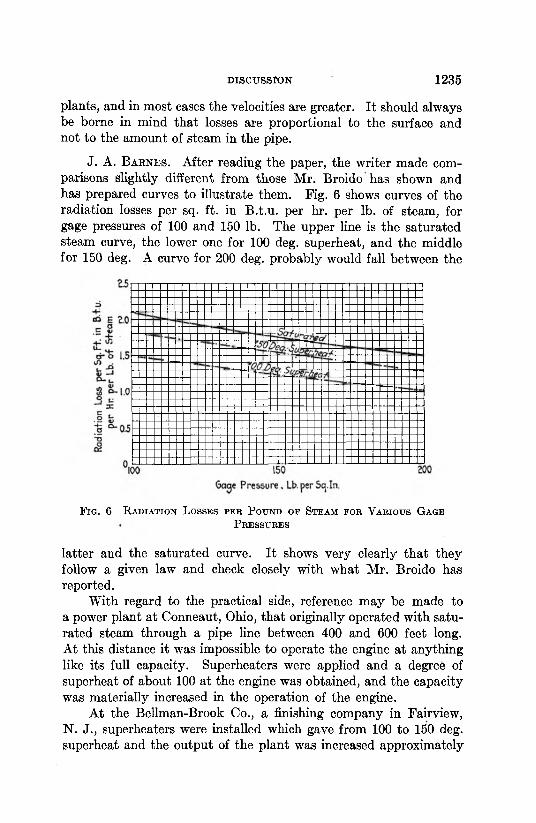
J. A. B a r n e s . After reading the paper, the writer made comparisons slightly different from those Mr. Broido has shown and has prepared curves to illustrate them. Fig. 6 shows curves of the radiation losses per sq. ft. in B.t.u. per hr. per lb. of steam, for gage pressures of 100 and 150 lb. The upper line is the saturated steam curve, the lower one for 100 deg. superheat, and the middle for 150 deg. A curve for 200 deg. probably would fall between the
F ig . 6 R a d ia t io n L o sse s p e r P o u n d o p St e a m f o r V a r io u s G a g e
P r e s s u r e s
latter and the saturated curve. It shows very clearly that they follow a given law and check closely with what Mr. Broido has reported.
With regard to the practical side, reference may be made to a power plant at Conneaut, Ohio, that originally operated with saturated steam through a pipe line between 400 and 600 feet long. At this distance it was impossible to operate the engine at anything like its full capacity. Superheaters were applied and a degree of superheat of about 100 at the engine was obtained, and the capacity was materially increased in the operation of the engine.
At the Bellman-Brook Co., a finishing company in Fairview, N. J., superheaters were installed which gave from 100 to 150 deg. superheat and the output of the plant was increased approximately
35 per cent, due entirely to the elimination of radiation losses, while practically the same thing was done in the Easton Finishing Company.
Curves of Figs. 1 and 2 of the paper seem to be contradictory. These curves represent the results of a number of tests or readings, and in plotting a curve, it is not possible to extend it through every point that is plotted. Usually such a curve is drawn to represent an average or a mean, and for that reason I assume that these curves are of this nature, and what apparently is a contradiction is merely due to the fact that they represent a series of averages.
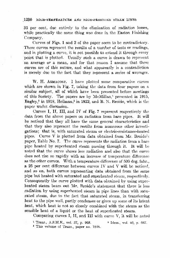
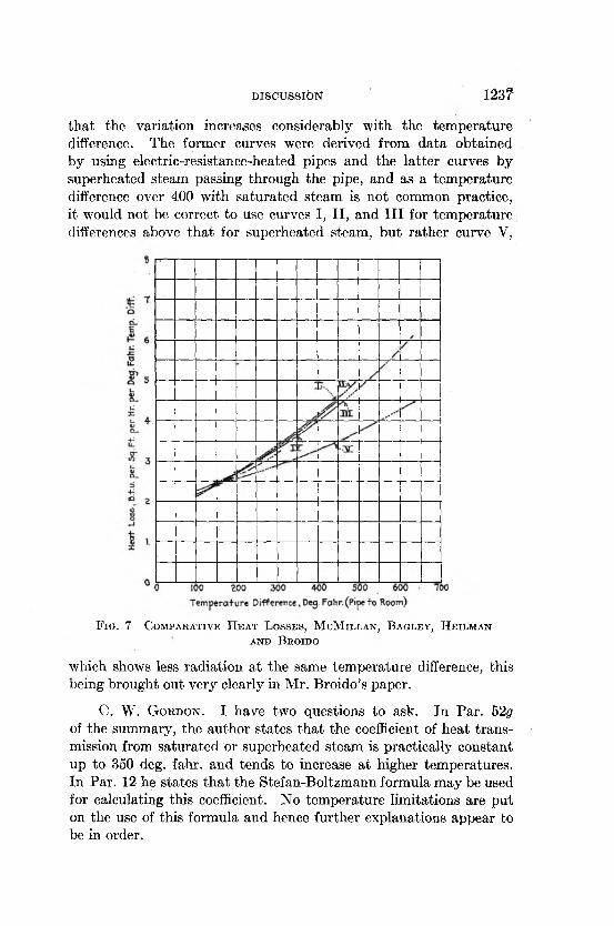
W. H. A r m a c o s t . I have plotted some comparative curves which are shown in Fig. 7, taking the data from four papers on a similar subject, all of which have been presented before meetings of this Society. The papers are by McMillan,1 presented in 1915, Bagley,2 in 1918, Heilman,3 in 1922, and B. N. Broido, which is the paper under, discussion.
Curves I, II, III, and IV of Fig. 7 represent respectively the data from the above papers on radiation from bare pipes. It will be noticed that they all have the same general characteristics and that they also represent the results from numerous other investigations; that is, with saturated steam or electric-resistance-heated pipes. Curve V is plotted from data obtained from Mr. Broido’s paper, Table No. 7. The curve represents the radiation from a bare pipe heated by superheated steam passing through it. It will be noted that the curve shows less radiation and also that the curve does not rise so rapidly with an increase of temperature difference as the other curves. With a temperature difference of 500 deg. fahr., a 25 per cent difference between curves IV and V will be noticed, and so on, both curves representing data obtained from the same pipe but heated with saturated and superheated steam, respectively. Consequently the curve plotted with data obtained by using superheated steam bears out Mr. Broido’s statement that there is less radiation by using superheated steam in pipe lines than with saturated steam, due to the fact that saturated steam, in transferring heat to the pipe wall, partly condenses or gives up some of its latent heat, which heat is not so closely combined with the steam as the sensible heat of a liquid or the heat of superheated steam.
Comparing curves I, II, and III with curve V, it will be noted1 Trans., A.S.M.E., vol. 37, p. 968. 2 Idem., vol. 40, p. 667.3 This volume of Trans., paper no. 1848.
1236 H IG H -TE M PER A TU R E AND H IG H -PR E S S U R E STEAM LIN ES
D ISCUSSIO N 123?
that the variation increases considerably with the temperature difference. The former curves were derived from data obtained by using electric-resistance-heated pipes and the latter curves by superheated steam passing through the pipe, and as a temperature difference over 400 with saturated steam is not common practice, it would not be correct to use curves I, II, and III for temperature differences above that for superheated steam, but rather curve V,
F i g . 7 C o m p a r a t iv e H e a t L o s s e s , M cM il l a n , B a g l e y , H e il m a n a n d B e o id o
which shows less radiation at the same temperature difference, this being brought out very clearly in Mr. Broido’s paper.
C. W. G o r d o n . I have two questions to ask. In Par. 52g of the summary, the author states that the coefficient of heat transmission from saturated or superheated steam is practically constant up to 350 deg. fahr. and tends to increase at higher temperatures. In Par. 12 he states that the Stefan-Boltzmann formula may be used for calculating this coefficient. No temperature limitations are put on the use of this formula and hence further explanations appear to be in order.
1238 H IG H -TE M PER A TU R E AND H IG H -PR E S S U R E STEAM L IN E S
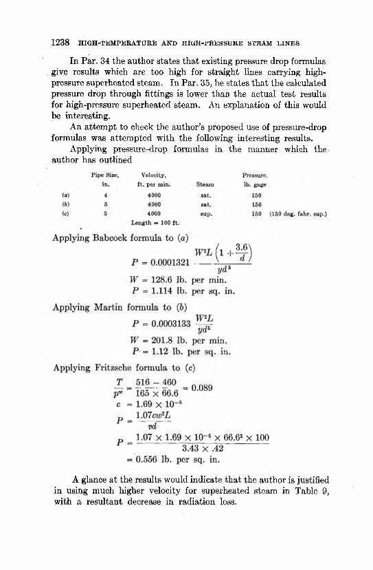
In Par. 34 the author states that existing pressure drop formulas give results which are too high for straight lines carrying high- pressure superheated steam. In Par. 35, he states that the calculated pressure drop through fittings is lower than the actual test results for high-pressure superheated steam. An explanation of this would be interesting.
An attempt to check the author’s proposed use of pressure-drop formulas was attempted with the following interesting results.
Applying pressure-drop formulas in the manner which the author has outlined
A glance at the results would indicate that the author is justified in using much higher velocity for superheated steam in Table 9, with a resultant decrease in radiation loss.
DISCU SSIO N 1239
J. H. L a w r e n c e . A short time ago we designed a large central station — probably the largest in the country — Hell' Gate Station, and we compared the actual losses in the steam line with the losses estimated by various formulas and while there should have been considerable drop, still when we came to measure it, it was so small that we thought there was something wrong. The loss was about one-half of the loss given by any formula in handbooks. We used no long radius bends. Every bend was made by using a fitting of some kind. Nevertheless the loss in the steam line was so small that it was almost negligible. The most serious loss was in the part where we had to provide a loop to take care of the expansion ahead of the throttle valve.
This is not the only case that has come to our attention. We have looked into this question at several stations and the loss did not check up with any of the known formulas.
We do not believe in low steam velocity. This paper mentions10,000 ft., but this we consider too low for most steam velocity in a large station. We use a maximum of 15,000 ft., except in certain cases where the lines would only be used in case of emergency. Here we do not hesitate to go to 20,000 ft. per min. In most handbooks there are certain rules about allowable velocity, something of the order of 6000 to 8000 ft. for saturated steam and 10,000 ft. per min. for superheated steam. Such information is very misleading, as the maximum velocity should increase with the size of the pipe used.
We have found that in the case of small sizes, the velocity should be very low; for the 2-in. pipe in the neighborhood of 2000 ft. per. min.; for 6-in. pipe the proper velocity is about 6000 ft.; and so on up to 15,000 ft. velocity which we use as the ordinary maximum regardless of size of pipe.
T h e A u t h o r . It is very true, as has been stated by Mr. Barrett, that the analysis of radiation losses in pipe lines in this paper was not based on the experiments of McMillan, Bagley, and Heilman, all of which were made with electrically heated pipes, and the object of which was mainly to determine the efficiency of various types of pipe covering. This paper was not intended for this purpose. Its object, particularly the first part dealing with radiation losses, was to show, first, that there is a difference between saturated and superheated steam as far as imparting of heat to a pipe wall is concerned; and second, that in comparing the radiation losses of satu
rated and superheated steam, not the direct heat in B.t.u. is to be considered, but the total heat losses in percentage of the heat conveyed in the steam through the pipe. As the Munich tests are believed to be the only extensive ones conducted with saturated and superheated steam flowing in the test pipe, only these tests could be considered and analyzed in the paper. In order to make a fair comparison, and to enable the reader to follow the analysis, the main data of the above tests were given in the paper.
Mr. Barrett looked at the paper only from the standpoint of radiation losses. I shall endeavor, however, to refer to some of the points in Mr. Barrett’s discussion, as they might be of general interest.
It could not be expected that the values of a given in Table 4 would give a smooth curve, as a depends not only upon the velocity of the steam, but also upon the temperature differences. The values of a given in the table are for two velocities with bare pipe, and one with covered pipe. The temperature difference, however, with the covered pipe was considerably less than that with bare pipe.
Mr. Barrett objects to the heat transmission coefficient between the steam and pipe wall given as 400 in Par. 52, because other investigators have found it to be considerably higher, or up to 2700. From Table 1 of this paper it is seen that at a temperature difference between the steam and the outside air of 250 deg., the heat loss per square foot of surface per hour in B.t.u. is 750. With a heat transmission coefficient of 400, the temperature of the wall must be 750 -f- 400 = 1.875, or less than 2 deg. below the steam temperature. At a wall temperature equal to the steam temperature, a would be infinitely large. As it is very difficult to measure accurately the temperature of the steam and the pipe wall, and a difference of 2 deg. is likely to occur, the value of a cannot be definitely fixed. 400 is mentioned in this paper only as a comparison with the value of superheated steam, which is only 32 at a velocity of about 80 ft. per second.
As shown on the curves plotted by Mr. Armacost while discussing this paper, the difference between the data of the tests analyzed in this paper and those of Messrs. McMillan, Heilman, and others, is very slight.
Mr. McMillan wonders why the difference between the heat transmission of saturated and superheated steam was gone into in such detail. As mentioned in Par. 18, this subject is of considerable interest as far as the use of superheated steam for heating and
1240 H IG H -TE M PER A TU R E AND H IG H -PR E S S U R E STEAM L IN E S
DISCUSSIO N 1241
drying purposes is concerned. So far as the author is aware, the influence of the velocity of superheated steam on the heat transmission, particularly in connection with the question of whether the pipe is wet or dry inside, has never before been discussed, and is believed to be of considerable interest to engineers.
Mr. McMillan’s statement that calculating steam line sizes on velocity is antiquated, and that the preferred method of calculating steam lines is based on allowable pressure drop, is not quite understandable, as the pressure drop is dependent on the velocity of steam, so that the results must be the same. In Par. 30 is mentioned why it is more advisable or possible to use higher velocities with,superheated steam. The velocity taken in Table 9 is in accordance with general engineering practice. That the pressure drop with these velocities is not excessive, is shown by the fact that it is only slightly greater than that for saturated steam, and with the exception of one case does not exceed 1 lb. throughout the range of the table.
In answer to Mr. Orrok’s question as to how the wall temperatures of the pipe were measured, thermocouples were placed just on the outside of the pipe, and held by Z-shaped bars, which were formed to fit snugly to the pipe, and being in metallic contact with the wall, obtained the same temperature as the pipe. The thermocouple was pressed to the pipe by these bars, and in this way the element was practically imbedded in metal having the temperature of the wall. With this arrangement, if carefully carried out, very reliable readings can be obtained, while if the element is only laid on the pipe, considerable errors may result.
When Mr. Lawrence, in comparing the pressure drop obtained at Hell Gate with that given in formulas, found that it was only one-half of that obtained by calculations, he probably figured with the old Babcock or Guttermuth formulas. If they were compared with figures obtained with the Fritzsche formula, as mentioned in the paper, they would probably check more closely. As a matter of fact, on several occasions I had opportunity to compare the pressure drop obtained by the formulas of Babcock and Guttermuth with that of Fritzsche; for large pipes particularly, the results obtained with the Fritzsche formula were only about one-half of the others, which rather checks with the findings at the Hell Gate Station.
The fact that the Stefan-Boltzmann formula may be used for calculating of radiation loss from pipe lines is not contradicted by
the statement that the coefficient of heat transmission from saturated or superheated steam is practically constant up to a temperature difference of 350 deg., and that it tends to increase at higher temperatures, as was questioned by Mr. Gordon. In accordance with the Stefan-Boltzmann formula the heat transmission varies with the fourth power of the temperature difference, so that it varies little at lower differences, and increases rapidly at the highest, and therefore, confirms rather than contradicts the statement.
With reference to the second question of Mr. Gordon as to why the friction in pipe lines at high pressures is less, while in fittings it is higher than that derived by calculating according to standard formulas for moderate steam pressures; this is probably due to the fact that in fittings the steam changes its direction, and a part of its kinetic energy is lost, and this is more pronounced at higher pressures than at the lower ones.
1242 H IG H -T E M PE R A T U R E AND H IG H -PR E S S U R E STEAM L IN E S