Embed Size (px)
Citation preview
No. 1839
COTTON-GINNING MACHINERY
B y S o lo m o n E . G i l l e s p i e , D a l l a s , T e x .
Member of the Society
Of the two classes of cotton grown in the TJrdted States — sea island or long-staple, and upland or green-seed — the former does not adhere to the seed and the lint can be pulled off clean by running it through rollers set close together, leaving the seed behind. Upland cotton, on the other' hand, adheres to the seed, and the present paper is devoted to a description of the apparatus developed since Eli Whitney’s epoch-making invention in 1792 jor mechanically handling the raw seed cotton, removing the lint therefrom, and forming it into shape suitable for delivery to the baling press.-
The cotton-ginning process comprises (a) elevating the cotton from the wagons in which it is brought to the ginnery to (b) a cleaner where the dirt, sand, leaf trash and other foreign substances are extracted; (c) elevating the cleaned cotton to (d) feeders which deliver it uniformly to (e) the gins where the lint is removed from the seed by the teeth oj circular saws mounted at close intervals on a rotating shaft, from which teeth it is (j) cleaned off pneumatically and (g) carried to a condenser, where it is formed into a “ bat ” and delivered to a press box for packing, wrapping and pressing. The latest developments oj the various devices employed in these steps are described and illustrated in the paper, and the author has included much valuable injormation jor designers in the way oj dimensions, relative proportions, speeds of operation, etc.
LONG before the dawn of history the cotton plant was cultivated in various parts of the world, and the earliest records of spin
ning its fleecy bolls are of such antiquity that it is difficult to obtain satisfactory evidence of its beginning. The name “ cotton ” itself is of Oriental origin, being derived from the Arabic “ koton ” or “ gootn.”
2 India is known as the motherland of cotton, and its earliest history is found in the Rig Veda hymn, composed fifteen centuries before the Christian era, which honors the “ threads of the loom,” and also three thousand years ago it was used as an ornamental shrub in Egypt.
Presented at the Spring Meeting, Atlanta, Ga., May 8 to 11, 1922, of T h e A m e r ic a n S o c i e t y o p M e c h a n i c a l E n g i n e e r s .
15
1 6 COTTO N -GIN N IN G M A CH INERY
3 Alexander the Great acquainted Europe with India, and with that singular plant “ vegetable wool,” and often referred to “ the trees of India bearing wool.” Cotton was first imported into England in 1298 A.D., and the manufacture of cotton goods thereafter became one of its greatest industries. In the United States cotton became an early experimental plant, beginning in Virginia in 1600 A.D. and after that date its growth was very rapid. During the war of the American Revolution and immediately thereafter, cotton culture began to receive considerable attention in the Southern States; along the coast, the valuable sea island cotton was raised, and later, in the interior, the upland or green-seed cotton was raised.
4 Before taking up the ginning of cotton it is well to consider its principal characteristics. There are two general classes or distinctive kinds of cotton grown in the United States, “ sea island ” and “ upland.” Sea island cotton does not adhere to the seed, and the lint can easily be pulled off clean, leaving the seed perfectly smooth. The staple varies from 1 | in. to 2 \ in. in length, and is of a light creamy silk color. While strong, it is finer than other kinds, and being about 0.00063 in. in diameter, has a more beautiful luster.
5 Upland cotton adheres to the seed, and appears to grow out of them more like wool from a sheep’s back. The seed, after being divested of lint as well as possible, still have a woolly appearance, and in a great many varieties a greenish color and hence upland cotton is referred to as “ green-seed ” cotton. The staple varies in length from f in. to If in. and its color ranges from white to a creamy tint. The staple is inferior in strength to the sea island type and coarser, being 0.00076 in. in diameter. The fibers are soft, elastic, moist and pliable, but the natural twist is rather inferior in character to that of sea island cotton, being irregular.
6 Good commercial cotton must possess certain well-defined external and internal characteristics. The external qualities, which are apparent to the touch or visible to the naked eye are: (a) Length of fiber, (b) fineness or smallness of diameter, (c) evenness and smoothness, (d) elasticity, (e) tensile strength, (/) color. The internal characteristics, which are discernible by a microscope, are: (a) Hollowness, or tubular construction, (b) natural twist, due to the collapsed tube, (c) corrugated edges, (d) moisture.
7 These characteristics are necessary to constitute a good mature cotton fiber, are essential in effecting the close union of the
SOLOMON E . G IL L E S P IE 1 7
filaments, and make cotton superior to any other fiber, vegetable or animal. And since the cotton fiber has such a delicate structure and great value, it is necessary that the machinery used in its ginning and cleaning be of such character that the least possible damage will be done to the staple in the process.
8 The first method to be employed in separating cotton lint from the seed was that of hand picking. The next method, originated in India about 300 B.C., made use of rollers, which when running close together would pull the lint through and leave the seed behind. The roller gin is now used principally for ginning sea island or long-staple cotton and has gone through a long process of development and improvement.
9 In the United States the great problem that presented itself in the early days of the industry was that of removing the seed from the upland or green-seed cotton. The roller gin in its crudely developed state at that time would handle the sea island cotton to a certain extent, but was not adaptable to and suitable for the upland cotton.
10 In 1792 Eli Whitney, of Massachusetts, went by boat to Savannah, Georgia, and there developed the first cotton gin, for which a patent was granted him two years later. The original Whitney gin was a hand-power and hand-fed gin, consisting of a horizontal wooden cylinder about 1\ in. in diameter and 2 ft. long, into which wire teeth were driven in rows spaced apart to admit the seed cotton, but with the teeth in each row so close together as not to admit seed. The teeth were all inclined the same way, making an angle of 55 deg. to 60 deg. with a tangent at the point of entry. The cylinder had suitable bearings at each end and a hand crank, and above and in front of the cylinder was a hopper to receive the seed cotton, while directly over it was a breastwork or stripping grate consisting of a timber lined with a metal strip having a series of slots through which the rows of teeth could pass, taking the lint cotton but obstructing the seed. The lint was removed from the teeth by means of a cleaner or brush consisting of four sticks with bristles and so constructed that it formed a tangential cylindrical coacting surface of bristles rotating in an opposite direction to that of the teeth and much faster. It was driven by an endless belt and idler. The gin was not continuous in action, as are the gins of today, but had to have its seed dumped from time to time as they accumulated.
11 Two years later, — May 12, 1796, — a patent was issued
1 8 COTTO N -GIN N IN G M A CH INERY
to H. Ogden Holmes of Augusta, Georgia, on a hand-fed and hand- operated gin similar to Whitney’s, except that it was continuous in operation, being so constructed that the seed would shed out as fast as they were delinted. This was also the first gin to use metal disks or saws, which were mounted on a square shaft with ends turned down for bearings and the saws separated by space blocks. The brush contained more than four bristle-filled sticks, and was driven in reverse direction to that of the saws and four or five times as fast. This gin would shed the seed continuously as fast as delinted, and the roll of cotton in the roll box would revolve just as it does in the saw gin of today.
12 A little later, larger power-driven gins were employed, Fig. 1, the transmission consisting usually of a large 8-ft. wooden bevel gear mounted on a vertical axis with an extended beam or arm to which a horse or mule was hitched, and a horizontal shaft with a wooden pinion worked in conjunction with the large bevel gear on which shaft a 12-ft. band wheel was mounted and from which the gin was driven at from 200 to 300 r.p.m. by means of a belt. In this system the gin was hand-fed from a platform above. The lint was discharged into a sack suspended beneath a hole in the floor back of the gin, sacking being the first system to be used in handling cotton in the market. Later, however, a lint room was built to receive the lint cotton, which was then carried out of doors in
’ %
baskets and put into a crude wooden press. This press was of very heavy mill construction, consisting of a single heavy box with discharge doors at the bottom and four large wooden corner struts or tension supports. An elevated platform was built of sufficient height to easily permit the placing of cotton in the press box from above, just below the overhead sills. The press screw was of wood and 15 in. in diameter with levers fixed to the top end and inclined downward to receive a rope to which a horse or mule was attached. Some presses had roofs over them, while others were left out in the open.
13 The ginning system was later improved by the addition of a mechanical feeder over the gin and a single lint condenser back of it, and also by the employment of the steam engine for motive power. As the demand for larger output grew, the ginneries were increased to two and three stands and the presses made more modern by the use of a 5-in. steel screw. In some cases the presses were equipped with large steam cylinders 30 in. to 36 in. in diameter, which operated much more rapidly than the screw press. These

SOLOMON E . G IL L E S P IE 19
2 0 CO TTO N -GIN N IN G M A CH IN ERY
small ginneries were commonly known as plantation gins and were a part of the equipment of each large plantation. As the cotton industry grew, however, and the large plantations were superseded by small ones, custom gins came into use, doing away with the plantation gin and compelling inventors to seek better methods of caring for larger capacities at the gins. At first belt carriers were installed back of each battery of gins, which received the lint from each of the single condensers and delivered it to the press box. This crude system, however, was later replaced by a single lint flue receiving the lint cotton direct from the various gin stands — which were in batteries of from two to six stands — and delivering it to a single large lint condenser or bat former, which then delivered it to the press. The lint flues were first constructed of wood, but later sheet iron was used, the diameter being about 18 in. at the smaller end and increasing as gins were added. There is a story in conneotion with the development of the lint flue that is related by one who is very high in the cotton-gin business, and who was in close touch with its early history and development. The first flue was a wooden box back of the gins leading to the condenser, and in its construction, it was deemed necessary that a wide belt be in the bottom of the flue to assist in carrying the lint cotton that might fall, and to assist further in its travel; but when time came to start the system the wide belt failed to operate, due to the driving mechanism being out of order, and a surprise resulted in the lint cotton being blown on to the condenser by the air produced by the brushes in the gins, which demonstrated that the wide belt was not necessary.
14 To care further for the large output of cotton at the cotton ginneries, the revolving double-box press was developed. In this press one box acted as a receiving chamber from the condenser and was provided with a tramper or packer which packed 500 lb. of lint cotton in it, after which it was revolved again, bringing the other empty box on to the receiving side while the one filled with cotton was pressed into a bale.
15 The standard cotton-bale boxes for presses are 27 in. by 54 in. by 10 ft.; the cotton is pressed from the latter dimension down to 36 in. and then six ties are put around it. Before being pressed, however, jute bagging is placed at the top and bottom of the cotton for wrappers. Upon releasing the pressure on the bale it usually expands to 40 or 42 in., making a finished bale 27 in. by 54 in. by 40 to 42 in. with a density of 12 lb. per cu. ft. A maximum

SOLOMON E . G IL L E S P IE 2 1
pressure of 10,000 lb. is required in packing a bale of cotton in the receiving chamber and 70,000 lb. to press a standard bale.
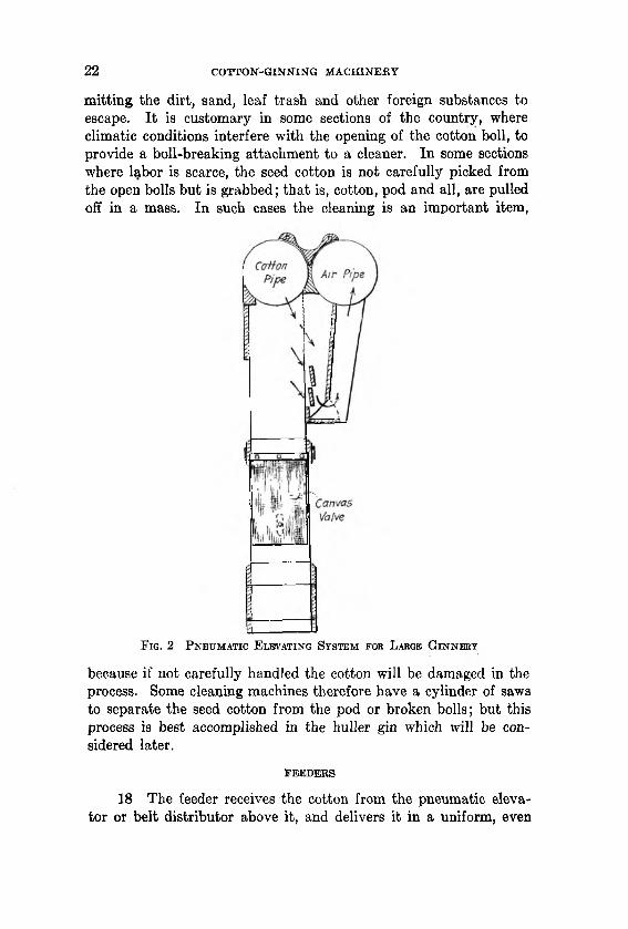
16 Mechanical elevating systems were also developed for use in the large ginneries. The earlier designs were belt carriers, consisting of slats of wood nailed or riveted to two narrow beltg, which would drag the seed cotton along from the point where it was fed on by hand to the point of delivery in the feeders. This process, however, required too much human labor, and one comprising a suction fan with vacuum box and belt distributor was next devised. In this system the cotton was sucked from the wagon through a pipe to the vacuum box, in which there was a wire screen to separate the cotton from the air, the cotton then falling on the spiked-belt distributor below by means of which it was delivered to each gin feeder. The screen area in these vacuum boxes was 1 sq. ft. of J-in. mesh screen wire to 14 to 20 saws. The pneumatic elevating system, Fig. 2, was also invented, and consisted of a vacuum chamber or elevated chute over each feeder and gin. This chute consisted of a chamber 12 in. by 53 to 60 in. by 6 ft. high with an air and cotton pipe at the top, a screen box attached on the upper back side and a heavy 12- to 16-oz. canvas valve near the center. This valve was so constructed that when the suction was applied it would close and prevent leakage of air through the valve, causing suction in the telescope pipe in the wagon. This would deliver cotton into the several elevator chutes and then periodically the air would be cut off by means of a valve trip, thus releasing the air suction, and the canvas valves would dro'p the cotton into the gin feeder. The screen in the pneumatic elevator to separate the cotton from the air is usually light No. 21 gage, |-in. mesh wire, and the! screen area is about one square foot to 10 saws. The fans used in these two elevating systems are of the steel-plat:e centrifugal type, varying in size from a 30-in. fan for a two-gin installation to a 45 to 50-in. fan for six gins. The peripheral speed of the suction fan-blast wheels varies from 11,000 ft. per min. to 13,000 ft. per min., which maintains a vacuum of14 to 16 in. of water.
SEED-COTTON CLEAN ER S
17 There are many kinds of machines in use for cleaning seed cotton, but the general principle, employed in them all, consists of agitating the cotton on a wire screen of -J-in. to £-in. mesh, per
2 2 COTTO N -GIN N IN G M A CH INERY
mitting the dirt, sand, leaf trash and other foreign substances to escape. It is customary in some sections of the country, where climatic conditions interfere with the opening of the cotton boll, to provide a boll-breaking attachment to a cleaner. In some sections where labor is scarce, the seed cotton is not carefully picked from the open bolls but is grabbed; that is, cotton, pod and all, are pulled off in a mass. In such cases the cleaning is an important item,
F ig . 2 P n e u m a t i c E l e v a t in g S y s t e m fo b L arge G i n n e r y
because if not carefully handled the cotton will be damaged in the process. Some cleaning machines therefore have a cylinder of saws to separate the seed cotton from the pod or broken bolls; but this process is best accomplished in the huller gin which will be considered later.
FEED ERS
18 The feeder receives the cotton from the pneumatic elevator or belt distributor above it, and delivers it in a uniform, even

SOLOMON E . ^G ILLESPIE 2 3
amount to the ginning roll box. There are two general types of feeders. The horizontal slatted-belt type that receives the cotton from the belt distributor or pneumatic elevator on a very slow-moving slatted belt and moves it horizontally up to a spiked drum or picker roller 9 in. to 11 in. in diameter, rotating 180 to 200 r.p.m. and is provided with a series of No. 8 spikes projecting 1 in. from the surface. These spikes lift the cotton over and throw it down a
chute into the ginning-roll box. Another general type, Fig. 3, receives the cotton from the elevator chutes or belt distributor onto two fluted rollers 5 in. to 6 in. in diameter rotating toward each other at i to 1 r.p.m. slowly feeding the cotton down where it is taken off by a picker roller similar to the one previously described, and is then whipped around a ^-in. mesh No. 16 gage wire screen that partly surrounds the picker roller at a distance of about \ in. therefore threshing the light leaf trash and sand out of it before delivering it to the ginning roll box. The latest improved feeders are among the most effective cleaning machines in use.
2 4 COTTO N -GIN N IN G M A CH INERY
T H E SEED-COTTON GIN
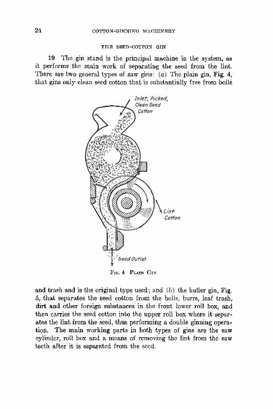
19 The gin stand is the principal machine in the system, as it performs the main work of separating the seed from the lint. There are two general types of saw gins: (a) The plain gin, Fig. 4,' that gins only clean seed cotton that is substantially free from bolls
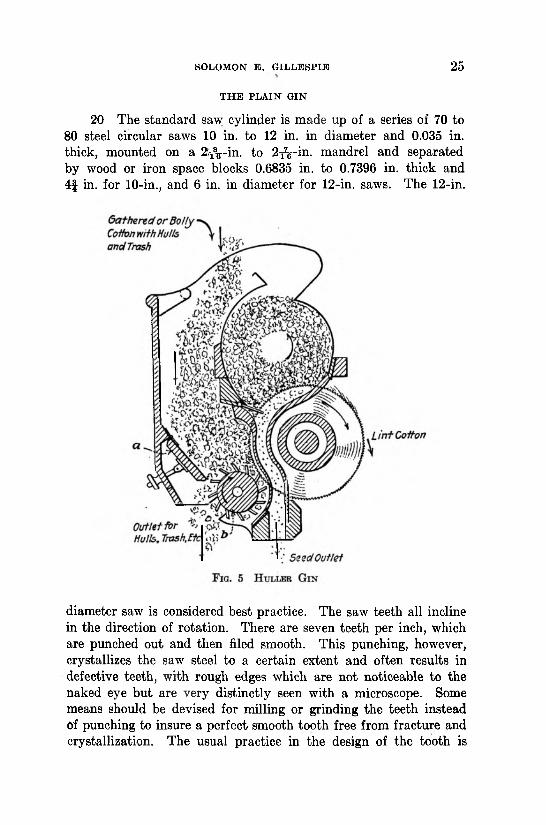
and trash and is the original type used; and (b) the huller gin, Fig. 5, that separates the seed cotton from the bolls, burrs, ,leaf trash, dirt and other foreign substances in the front lower roll box, and then carries the seed cotton into the upper roll box where it separates the lint from the seed, thus performing a double ginning operation. The main working parts in both types of gins are the saw cylinder, roll box and a means of removing the lint from the saw teeth after it is separated from the seed.
F ig . 4 P l a in G i n
SOLOM ON E . G IL L E S P IE 2 5
T H E PLA IN GIN
20 The standard saw cylinder is made up of a series of 70 to 80 steel circular saws 10 in. to 12 in. in diameter and 0.035 in. thick, mounted on a 2^-in . to 2^-in . mandrel and separated by wood or iron space blocks 0.6835 in. to 0.7396 in. thick and 4f in. for 10-in., and 6 in. in diameter for 12-in. saws. The 12-in.
diameter saw is considered best practice. The saw teeth all incline in the direction of rotation. There are seven teeth per inch, which are punched out and then filed smooth. This punching, however, crystallizes the saw steel to a certain extent and often results in defective teeth, with rough edges which are not noticeable to the naked eye but are very distinctly seen with a microscope. Some means should be devised for milling or grinding the teeth instead Of punching to insure a perfect smooth tooth free from fracture and crystallization.. The usual practice in the design of the tooth is

2 6 COTTO N -GIN N IN G M A CH INERY
to make both the front and back edges straight lines. In some cases, however, the front edges have been made straight and the back .edges convex) resulting in what is known as “ hog-back ” teeth. The inclination of the teeth edges, Figs. 6 and 7, with a radial line through the point are 36 deg. for the front edge and 57 deg. for the back edge, the two edges making an angle of 21 deg. with each other at the point; this, however, may vary to suit certain working conditions later referred to. The saws rotate with a tooth travel of 1000 to 1250 ft. per. min. for brush gins and 1400 to 1900 ft. per min. for air-blast or pneumatic gins.
21 The roll box, Fig. 8, consists of a series of ribs between
the saws with a half-rib at each end, a back hollow above the ribs, an inlet opening or feed inlet at the top, a cover on the front side with a seed grate attached, and a shield or cover for the exposed portion of the saws below the roll box. In the development of the gin it was found by experiment that the process of ginning worked best by placing the roll box above the saws, thus permitting the roll of cotton to rest upon them, Fig. 4; the saw teeth in taking hold of the cotton fibers would cause the whole mass of cotton to revolve in reverse direction, and usually at about a fifth of their velocity, depending upon the quantity of cotton in the roll box and the hardness of the roll.
22 The cotton roll is theoretically round, Fig. 8, and the same diameter as that of the saws; but due to the necessary working

SOLOMON E . G IL L E S P IE 2 7
conditions outlined in Pars. 23-26, its perfect roundness is distorted.
23 The saws are caused to project up into the roll box from ljig- in. to 1-.̂ in., 1 -/g- in. being considered the best practice. The cotton roll merely rests upon the saws, and the saw teeth, Eig. 4, only project into it. The cotton roll itself when rotating is hollow due to centrifugal force and the cavity in the center from 25 per cent to 50 per cent of its diameter. It is best practice for
the roll of cotton in the roll box to be as soft as possible, that is, with as large a cavity as possible, because this prevents the cotton fibers from wedging into the throats of the saw teeth, cutting and knapping the fibers, and also permits the fibers caught by the saw teeth to disentangle from the mass of the roll without breaking off; this precaution is especially necessary when the saw teeth are traveling at a high velocity.
24 The rib is tangent to the theoretical roll at its lower side; but the curve of the rib cuts up into the theoretical roll with a radius of 37 per cent of the saw diameter D, and at the upper edge of the rib, from 1 | to 2 in. above the point where the saw

2 8 COTTO N -GIN N IN G M A CH INERY
teeth pass through there is an offset dropping the working line back tangent to the theoretical roll, to permit the cotton fibers that were pulled between the ribs and not carried away by the saw teeth, Fig. 4, to free themselves from the ribs. The ribs are usually made of cast iron and at the points where the saw teeth pass between them they are chilled for an inch or so each way, Fig. 6, thus making a hard working surface that exhibits very little wear. The space between the ribs and the point where the teeth pass through is 0.125 in. wide and increases in width in each
F i g . 8 P r o p o r t io n s o p P l a i n - G i n R o l l B o x
direction therefrom. The wearing surface of the rib as well as the edges are ground smooth and polished. The lower end of the rib is extended downward beyond the circle of the saw and attached to a rail or bar and the upper end extended just above the offset to attach likewise to a bar or rail, while the inner surface is ground to the curvature (0.37J5), of the theoretical roll.
25 The back hollow begins at the upper end of the rib, tangent to the theoretical roll, and curves inward and upward with a radius of 42 per cent of the saw diameter D to give the roll a proper density at the ginning point below and also pack it just before reaching the inlet opening at the top. This opening is 28 per cent of the saw diameter D, and is for the purpose of
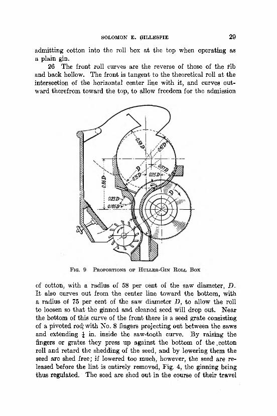
SOLOMON E . G IL L E S P IE 2 9
admitting cotton into the roll box at the top when operating as a plain gin.
26 The front roll curves are the reverse of those of the rib and back hollow. The front is tangent to the theoretical roll at the intersection of the horizontal center line with it, and curves outward therefrom toward the top, to allow freedom for the admission
of cotton, with a radius of 58 per cent of the saw diameter, D. It also curves out from the center line toward the bottom, with a radius of 75 per cent of the saw diameter D, to allow the roll to loosen so that the ginned and cleaned seed will drop out. Near the bottom of this curve of the front there is a seed grate consisting of a pivoted rod) with No. 8 fingers projecting out between the saws and extending \ in. inside the saw-tooth curve. By raising the fingers or grates they press up against the bottom of the .cotton roll and retard the shedding of the seed, and by lowering them the seed are shed free; if lowered too much, however, the seed are released before the lint is entirely removed, Fig. 4, the ginning being thus regulated. The seed are shed out in the course of their travel

3 0 COTTO N -GIN N IN G M A CH INERY
from the seed grate to the point where the saw teeth pass between the ribs, the seed that are free from lint dropping out of the roll on' the ribs below and escaping to the seed conveyor below. The center of the roll box is not directly above the center of the saws because it would cause the ribs below to be too flat and not permit the seed to slide down out of the way, therefore the center roll box is 25 per cent of the diameter D in front of the vertical
center line. The exposed portion of the saws below the roll box is covered with a shield to prevent injury to the operator; some roll boxes, however, have fronts that extend down and cover the exposed saws.
27. The saw teeth in traveling under the cotton roll take hold of some of the fiber and carry it between the ribs, leaving the seed in the roll box to be shed out as above explained. Each saw tooth that is loaded with lint cotton, amounting to from 0.000001418 lb. to 0.000001194 lb. per tooth from brush gins and

SOLOMON E . G IL L E S P IE 3 1
from 0.000001084 lb. to 0.000000934 lb. per tooth for air-blast or pneumatic gins, being 25 to 40 fibers per tooth based on 29,000,000 fibers per pound, must be unloaded or cleaned before it returns to the roll box again. The removal of the lint from the saw teeth is accomplished by means of a brush, Fig. 10, consisting of a series of f-in. by 1-in. sticks, usually 22 in number, in which bristles are inserted, usually projecting 1 in. from the stick. These sticks are mounted on a series of drum heads on a shaft I f f in. to 2fa in. in diameter. The outside diameter of the brush cylinder is usually 15 in. Each brush has four wings 1 in. by 6 in. on each end head. In the operation by the brush gin the brush is set up to the saw cylinder so that the tips of the bristles overlap the saw teeth just tV in. and are then caused to rotate in the reverse direction to that of the saws, and at a peripheral speed of 6300 to 6900 ft. per min. or approximately six times as fast as the saw-teeth travel. When the bristles are new they have a wiping effect on the saw teeth, but after considerable use the tips wear off to such extent that they do not touch the saw teeth, and it is only the air blast generated by the brush that removes the lint. At the rear of the brush there is a board or sheet-metal cut-off, similar to that of a fan, and just above and between the saw cylinder and the brush there is a parting board that directs the air current on to the saw teeth, removing the lint and at the same time deflecting the motes out of the general current by centrifugal force with the assistance of the mote board, while the lint is blown into the lint flue below. The mote board is just below and between the saw cylinder and the brush, and is adjusted so that in the regulation thereof the motes just pass out while all of the lint cotton is caught in the lint flue. The usual air current or pressure produced on the saw teeth by the brush varies from 5 to 6.5 in. of water, and in its travel to the lint- flue main body it expands until the pressure in the flue is | to £ in. of water.
28 The discovery that the air blast generated by the brushes had such an important part in removing the lint from the sawteeth led to the discovery of the pneumatic gin. Figs. 11 and 12 show two different types of this gin. One (Fig. 11) discharges the motes below, while the other, Fig. 12, discharges them over the top of the air lip. In the early air attachments the discharge-nozzle opening was f a in. to i in. wide and extended 1 in. beyond each end saw; after continued development, however, these openings were reduced to \ in. to f a in. The air blown from the lip

3 2 COTTO N -GIN N IN G M A CH INERY
opening continues to hug the sheet that leads to the lint-flue opening, and this sheet is brought up to within -fa in. to in. of touching the saw teeth. The lint opening is just wide enough to receive all the air discharged from the air nozzle, and in addition thereto a small amount of the outside air is injected by the dynamic action of the air current. There is thus a slight current from the outside leading into the lint flue, to insure that there will not be a loss of lint fibers on the outside, which would be the case if the
reverse action took place. The air pressure at the nozzle outlet is usually from 8 to 12 in. of water. The various pressures for other points in and around the air nozzle for the two types of gins considered are as shown in Figs. 13 and 14. The pressure in the lint flue at the rear of the gins varies from 0.7 in. to 1.0 in. in the rear of the gins to 0.5 in. to 0.65 in. in the lint-flue uptake to the condenser.
T H E H U L L E R GIN
29 The operation of the huller gin is very similar to that of the plain gin, in that the saw cylinders and the methods of re

SOLOMON E . G IL L E S P IE 3 3
moving the lint therefrom are the same. The roll-box construction is also the same except that there is an additional huller roll box in front of the ginning roll box, Fig. 5 and Fig. 9, for separating the seed cotton from the burrs, sticks, trash, etc., and the cotton is delivered into the huller roll box first, Fig. 5, and from there is carried up into the ginning roll box by the saws; hence the feed to the ginning roll box isi from below instead of from the top, as is the case with" the plain gin. The huller roll box, Fig. 5, consists of a
chamber in which the cotton is fed, and this chamber has a hinged removable front cover a, with an inclined sheet or board for regulating the refuse discharge, and a huller picker roller b, in. to 4 | in. in diameter, with 10 to 16 longitudinal rows of No. 8 spikes set at an angle of 30 deg. to radius of point where they enter roller. These spikes are alternated and in circular rows of 5 to 8 spikes between each pair of saws, and project out £ in. to 1 in. from the roller, which rotates at from 300 to 700 r.p.m. There is also a set of huller ribs, Fig. 7, to prevent the hulls and trash from being carried into the upper or ginning roll box, thus performing a double

3 4 COTTO N -GIN N IN G M A CH INERY
ginning process. The huller ribs partly surround the huller picker roller, Fig. 9, and the outer or working surface of the rib is \ in. to f in. from the tips of the saw teeth; just below the seed grate the rib curves out and is fixed to a rib rail or bar.
30 In the operation of the huller gin the cotton, Fig. 5, is fed
F iq . 13 Am P r e s s u r e a t V a r io u s P o i n t s i n P n e u m a t i c G i n S h o w n i n F i g . 11
into the huller roll box, the spiked picker roller rotating in the reverse direction to that of the saws, spikes inclining backward. The cotton is thus thrown on to the saw teeth and carried up into the ginning roll, leaving the trash, a part of which is shed out; but as the quantity increases, the box front is swung out by hand, discharging the foreign' substances. When there is a large amount of trash the picker roller is pulled out from the ribs and the inclined

SOLOM ON E . G IL L E S P IE 3 5
board moved back, thus permitting the trash to shed out in front of and behind the roller; but if there is only a small quantity, the huller roller should be set up close to it, to- prevent the dropping of locks of cotton. The huller ribs are spaced sufficiently apart at
F ig . 14 A ir P r e ssu r e at V arious P o in t s i n P n e u m a t ic G in S h o w n i n F ig . 12
the point where the teeth pass between to permit the seed cotton to pass through ipto the ginning roll box. The lint is removed from the saw teeth by means of a brush or current of air as has been described for plain gins, and the operation of the ginning roll box in shedding the seed is the same. The lint cotton is removed from the saw teeth and passes into the lint flue which has inlets from the

3 6 COTTO N -GIN N IN G M A CH INERY
various gins set in battery. The size of the lint flue varies according to the number and size of gins, the general practice being to have about three square inches per saw.
T H E CONDENSER
31 The lint flue delivers the cotton into the condenser which consists of a large horizontal drum covered with 8-mesh No. 21 wire screen. The drum is usually 54 in. long, the same as the cotton bale, and its diameter is usually 30, 40, 50, 60, or 72, in. respectively, for 100, 175, 250, 325 or 400 saws. The screen drum, Fig. 15, is mounted in a housing that spirally circumscribes it with air outlets at the ends and two doffing rollers at the discharge side, the lower one having flaps of thin ^-in . light cloth-backed rubber. The rollers receive the lint cotton from the drum and deliver it on the lint sli&e and then into the receiving chamber of the press box. The portion of the screen drum exposed to the cotton air current is about 75 per cent, and there is 1 sq. ft. of screen provided for every 5 to 6 saws; but when the drum rotates it travels at a rate of speed of 50 to 80 ft. per min. for the smallest up to the largest-size condenser. This is equivalent to a screen exposure, when running, of from 2 sq. ft. down to 1 sq. ft. per saw per min. The peripheral speed of the doffing rollers should be the same as that of the screen drum. From the condenser the lint cotton is delivered by the doffing rollers to the lint slide, thence into the press box.
T H E CO TTO N -G IN N IN G PROCESS
32 The seed cotton is brought to the cotton-gin plant in quantities of 1600 lb. when clean-picked cotton and of 2000 lb. to 2200 lb. when gathered or grabbed cotton. When ginned there will be a finished bale weighing about 500 lb. and 1050 lb. of cotton seed; the remainder is refuse, as trash, hulls, dirt and other foreign substances. The seed cotton is usually hauled in wagons from which it is sucked off through a telescope by means of air-suction steel- plate centrifugal fans operating at a blast-wheel peripheral speed of 11,000 to 13,000 ft. per min., and producing a vacuum of 14 to16 in. of water. In the course of its travel the cotton is carried through a cleaner where it is agitated on a screen to remove the foreign substances; thence it passes to the elevating system where

D ISC U SSIQ N 3 7
the air is separated from it, and is dropped into the gin feeders, where further cleaning is performed. The cotton is next delivered to the gin in such quantity as will not gorge the roll box, but will be sufficiently to insure a nice, moderately soft, pliable ginning roll. If the cotton is clean picked it can be delivered direct to the ginning roll in a plain gin; but if gathered or grabbed, it will contain hulls, etc., and should be delivered to a huller roll box.
33 The seeds fall from the roll box down into a seed conveyor from which they are delivered to the customer’s seed box or into a seed storage house. The hulls, trash and foreign substances are conveyed outside of the gin house to the boiler room for fuel, — that is, that part that is combustible, — or hauled off to be used later as fertilizer. The motes are also conveyed out and in some instances used for low-grade fiber stock. The lint cotton passes from the gin to the lint flue and then to the condenser, where it is separated from the air and formed into a bat. It is then delivered into the press box for packing, wrapping and pressing, ready for the market, and after marketing is compressed and rewrapped before export.
DISCUSSION
A. W. M e r k e l . We have on file a copy of the drawing covering Eli Whitney’s patent, and it shows very clearly the design as produced by him. This drawing bears date of March 14, 1794, which is presumably the date the patent was issued.
Whitney, like most inventors, never realized much in a financial way from his patent, because other parties began to manufacture the cotton gin, and it cost him very dear in time and money to carry his fight for justice through the courts. Finally becoming discouraged he left the South and returned to New England where he achieved success in other lines of manufacture.
All gins made for a number of years were of the plain gin type, as shown in Fig. 4.
The first attempt at making a gin to separate the hulls was in 1858. These first huller gins were of the single-rib type, and it was not until 1879 that the double-rib huller gin appeared. The first successful double-rib gin was brought out in 1879 by F. E.

3 8 COTTO N-GINNING M A CH IN ERY
Smith, a New, Englander who had moved South and was at that time associated with the Daniel Pratt Gin Co., of Prattville, Ala.
The single- and double-rib huller gins accomplish the same results, that is they remove the hulls and trash from the seed cotton, but the double-rib gin has the advantage in that it will separate the hulls from the seed and discharge' them into different receptacles, while the single-rib gin discharges them together.
The rib of the single-rib gin has a projection which extends towards the front, and which takes the place of the outside or hulling rib of the double-rib gin.
The pneumatic gin, described by the author, appeared in 1893, and was patented first by R. King of Mansfield, La.
It is interesting to note that although there have been numerous improvements in pneumatic or air-blast gins, as they are generally known, the original idea of Eli Whitney remains the best way of ginning cotton.
There is practically no difference in the rate of ginning, or in the sample produced by the air-blast and brush gins, on good cotton, but the latter has the advantage in the power required. For instance, in a four 70-saw outfit, which has four 70-saw gins, the four brushes will require 10 hp. to drive them, while with four 70-saw air-blast gins there will be required a 35-in. fan which will require 18 to 20 hp. to produce a pressure at the nozzle of 12 in. of water. This shows a saving of 8 to 10 hp. in favor of the brush-gin outfit.
The air-blast has the advantage of requiring fewer belts, and not having a brush to get out of balance, but this is offset by the fact that the brush will clean the saws better when ginning green or damp cotton in spite of the statement that the bristles soon become worn so that they will not touch the saws and that it then acts as an air-blast gin. If it does it produces a blast which hits the spot better than that produced by the fan.
Cotton gins are classed as “ agricultural implements,” which as a class do not require very close machine work, but the ribs, saws and space blocks which hold the saws apart must be accurately machined. The ribs must be carefully ground and polished so that they will allow the lint cotton to pass between them, and at the same time prevent the seed passing through. The polish is to prevent the lint being damaged by hanging to the ribs and to allow it a smooth, easy passage. The saws must be trained to run

D ISC U SSIO N 3 9
in a vertical plane, because if they were to rub against the ribs they would damage the lint and probably set fire to it. The space blocks must be accurate to the thousandth of an inch, in order to bring the saws exactly in the center of the space between the ribs. All this work must be done by men who have had long experience at this line, and it takes several years to become proficient in the art.
In regard to the present method of punching saws making defective teeth, it is our opinion that punching and filing make a better, smoother tooth than milling. The writer has seen some milled teeth and has noticed that the milling cutter leaves a worse burr than does the punch, and since it would be necessary to file the burr in either case, it seems that punching is the better proposition, as it is very much faster than milling.
Gin saws are made in two thicknesses, 0.035 and 0.037 in., most of them being 0.037 in. thick. They are made of English and American steel.
Before the late war English steel was used almost exclusively, as the American steel was a very inferior product, but during the war as it was almost impossible to get shipments of English steel, the American firms began to improve their product, so that now, the American steel is just as good as the English.
In enumerating the kinds of power used to press cotton, the author did not mention hydraulic. This power is the most popular at present, and the general practice is to use an 8|-in. diameter ram with 1800 to 2000 lb. per sq. in. pressure. This same power is also used to tramp the cotton and for this purpose a 3f-in. ram with the same maximum pressure is used, but it i§ seldom that the maximum pressure is required for tramping.
To produce the pressure there is used a triplex hydraulic belt- driven pump, protected by a relief valve to prevent bursts, should the operator allow the pressure to run too high.
The horsepower required to gin cotton varies considerably. For instance, a four 70-saw outfit with 12-in saw gins, ginning at the rate of 500 lb. of lint cotton in 15 min., will require about 60 hp., while if the rate of ginning is increased to 500 lb. in12 min., the power required will increase to 70 hp., an increase of 16f per cent.
The first successful elevator for elevating cotton from the wagon was produced in 1879 by the man who now heads one of the large gin manufacturing companies. The most efficient ele

4 0 COTTO N -GIN N IN G M A CH INERY
vating system of today is the one that makes use of a belt to distribute the seed cotton to the different feeders.
The combined output of all the cotton gin factories is estimated to be approximately 6000 gins per year. In normal times it is no trouble for the trade to absorb this number, because the ginning machinery is operated by negroes who give it such poor care that in a few years the gins must be repaired or discarded. The writer has known of gins that have given good service for 20 to25 years, but that is the exception to the rule. The weak parts are essential parts of the gin, and are the saws and brush which will rarely last more than two seasons without being repaired.
There are made every year a number of hand gins with 10 or 20 saws. These are manufactured for use in experimental stations in this country, but the larger part of those produced are exported to South America. They are used in the districts that have not been opened up by railroads, and in the mountains where all products have to be brought out on the backs of mules, or other similar conveyance. There is also manufactured a small press that will press a 100-lb. bale, instead of the standard, 500 lb., and this is used by the export trade for the same reason.
There are several things needed to improve the common practice in ginning cotton.
First, some inexpensive way to take the dust and fine lint out of the gin house, which is especially bad on the operators when ginning dry, dusty cotton.
Another is some way to improve the sample of cotton that has been "blighted by the boll weevil.
The boll weevil will often puncture only one lock of a boll of cotton. This lock then fails to mature and is picked along with the other locks of this boll. It is small and hard and when it gets into the gin the saws tear it apart, but the fibers instead of being nearly straight are very kinky. These fibers are, of course, mixed with the others and as they are curly and kinky, they will show up in the sample, thereby giving it not only a bad appearance but also lessening its value.
As previously stated, the brush type gin is better for ginning under all conditions, yet to overcome one of its disadvantages there is needed a better brush than is commonly used, and one that can be cheaply built.
After the cotton is baled in the ordinary press it is repressed

D ISC U SSIO N 4 1
or compressed before it is shipped any distance. There should be a strong, cheaply constructed press; strong enough to get the required density in the bale in the first pressing operation, and cheap enough to be installed in every outfit.
W. E. C a l d w e l l . The paper covers the subject of cotton- ginning machinery in an admirable manner, especially from the viewpoint of the designer. However, it is to be regretted that space was not availably for a more thorough treatment of the subjectf for the benefit of those responsible for the operation of gins.
Cotton-ginning machinery has reached a high state of development within recent years, so far as performing the service intended is concerned, but the reliability for continuous operation is far from satisfactory. Ginning plants operate at the lowest annual load factor of any plants of equal magnitude in existence and during the cotton season every idle moment is expensive for the owner. Nothwithstanding this, however, it does not appear as though much effort has been directed towards rendering ginning systems more reliable in operation. The usual troubles encountered by cotton ginners are due to the too frequent use of set screws and clamped joints by the gin manufacturers instead of keys; overloaded belts occasioned by the use of small pulleys and low belt speeds; and lastly, fans and their piping arrangement. There does not seem to be a fan on the market today which is equal to the service and abuse encountered in the average cotton gin. Present-day gin fans are an improvement over those in use ten years ago, at which time the ordinary steel plate exhaust fan was employed and usually operated above a safe speed to obtain the desired pressure or suction. The improvements which have been effected since that time were in the substitution of forward curved vanes and an increase in the number of vanes. Despite these changes which have improved the characteristics of the fans it is necessary to operate them at a speed so high that their destruction occasionally results, or the life of the runner, bearings and shaft is materially reduced. The writer recently witnessed the destruction of two new fans, supplied by a reputable manufacturer, while in operation at 10 per cent below nominal safe speed. This may be accounted for by the fact that manufacturers’ shop speed tests are conducted with closed suction or discharge, hence there is but little pressure difference on the vanes to assist in starting the initial buckling, which
4 2 CO TTO N -GIN N IN G M A CH INERY
always precedes the ultimate destruction of the runner. The pressure difference while relatively slight is of some moment, especially with wide runners, since its effect is in the same direction as that of the centrifugal force.
With the larger plants employing batteries of five or six 80- saw stands it is customary to supply a size 45 or 50 fan for the blast air, operating at a peripheral speed around 13,000 ft. per min. to give the desired results. As the bursting speed of the usual runner for a fan of this size is in the neighborhood of 14,000 ft. per min. the writer feels that the margin of safety is too low for continuous operation and that it is possible to improve the runners by the use of stiffer and better construction to increase the bursting speed to beyond 17,000 ft. per min.
It is probable that in many instances equally good results may be secured by running the fans at a lower speed than that recommended by cotton-gin manufacturers, although operators of gins do not feel inclined to order the change until trouble actually occurs. It would seem to the writer that air-blast gins have been developed to accommodate the fans now on the market, whereas a fan should be designed better to meet the requirement of ginning systems. Perhaps it would be advantageous to employ a fan somewhat on the order of the cupola blower, which has a better pressure-volume characteristic than the usual volume fan, as well as greater efficiency, although the efficiency is relatively unimportant considering the low annual load factor of ginning plants. In any event it seems extravagant to advocate the use of a volume fan for this work, having an outlet opening over four times as great as the total blast area of the gins. It would be interesting to know the volume of air delivered per saw under normal operation, for a given air pressure in the main duct at the gin stand. The duct pressure is more easily measured than the nozzle pressure and the relation of this pressure to the air flow would provide useful information for determining the proper size as well as proper speed for the fan. The figures quoted by the manufacturers cover a wide range, but the average quoted is in the neighborhood of20 cu. ft. per saw with a 12-in. nozzle pressure.
The author quotes the tooth travel of pneumatic gins at from 1400 to 1900 ft. per min. What determines this upper limit of saw speed? If the limit is imposed by the blast air velocity, could not this be increased by reducing the area of the blast opening

D ISC U SSIO N 4 3
and employing a higher pressure, thus increasing the capacity of the gin?
The author describes the pneumatic elevator but fails to mention the belt distributor which is quite popular in many sections of the cotton region, and there are a few instances where it has replaced the pneumatic elevator after one or two seasons’ operation of the latter. From the writer’s point of view the pneumatic elevator is superior to the belt distributor, considering the power saving, greater simplicity, ease of operation and saving of time between bales. Has the belt distributor any real advantages over the pneumatic type or is the selection merely a matter of personal preference?
It would be interesting to know the power consumption of different-sized outfits and whether or not the air-blast systems are as economical in this respect as the brush type. The power consumption is an important item when contemplating the installation of an oil-engine drive, or other prime mover having limited overload capacity. It is appreciated that the power consumption of the fans will vary with different installations, but if the author is able to itemize the consumption of the different pieces of apparatus under average conditions it will place valuable data before the members of the Society.