Embed Size (px)
Citation preview
Slide 1 Nokia Siemens Networks / CTO IE Packet Transport Evolution
NNI protection LACP alternative
Zehavit Alon
September 2010V03
Slide 2 September, 2010 Nokia Siemens Networks / CTO IE Packet Transport Evolution
NNI protection using LACP
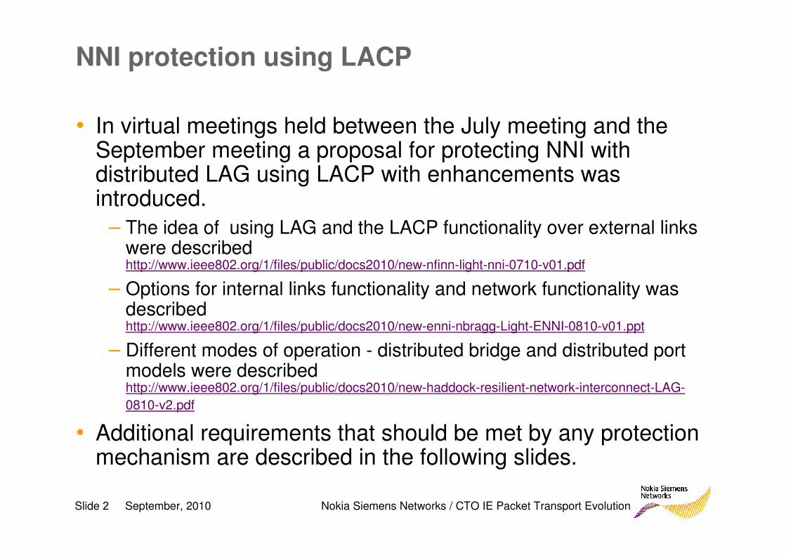
• In virtual meetings held between the July meeting and the September meeting a proposal for protecting NNI with distributed LAG using LACP with enhancements was introduced.
– The idea of using LAG and the LACP functionality over external links were describedhttp://www.ieee802.org/1/files/public/docs2010/new-nfinn-light-nni-0710-v01.pdf
– Options for internal links functionality and network functionality was describedhttp://www.ieee802.org/1/files/public/docs2010/new-enni-nbragg-Light-ENNI-0810-v01.ppt
– Different modes of operation - distributed bridge and distributed port models were described http://www.ieee802.org/1/files/public/docs2010/new-haddock-resilient-network-interconnect-LAG-
0810-v2.pdf
• Additional requirements that should be met by any protection mechanism are described in the following slides.
Slide 3 September, 2010 Nokia Siemens Networks / CTO IE Packet Transport Evolution
Requirement 1 – standardization
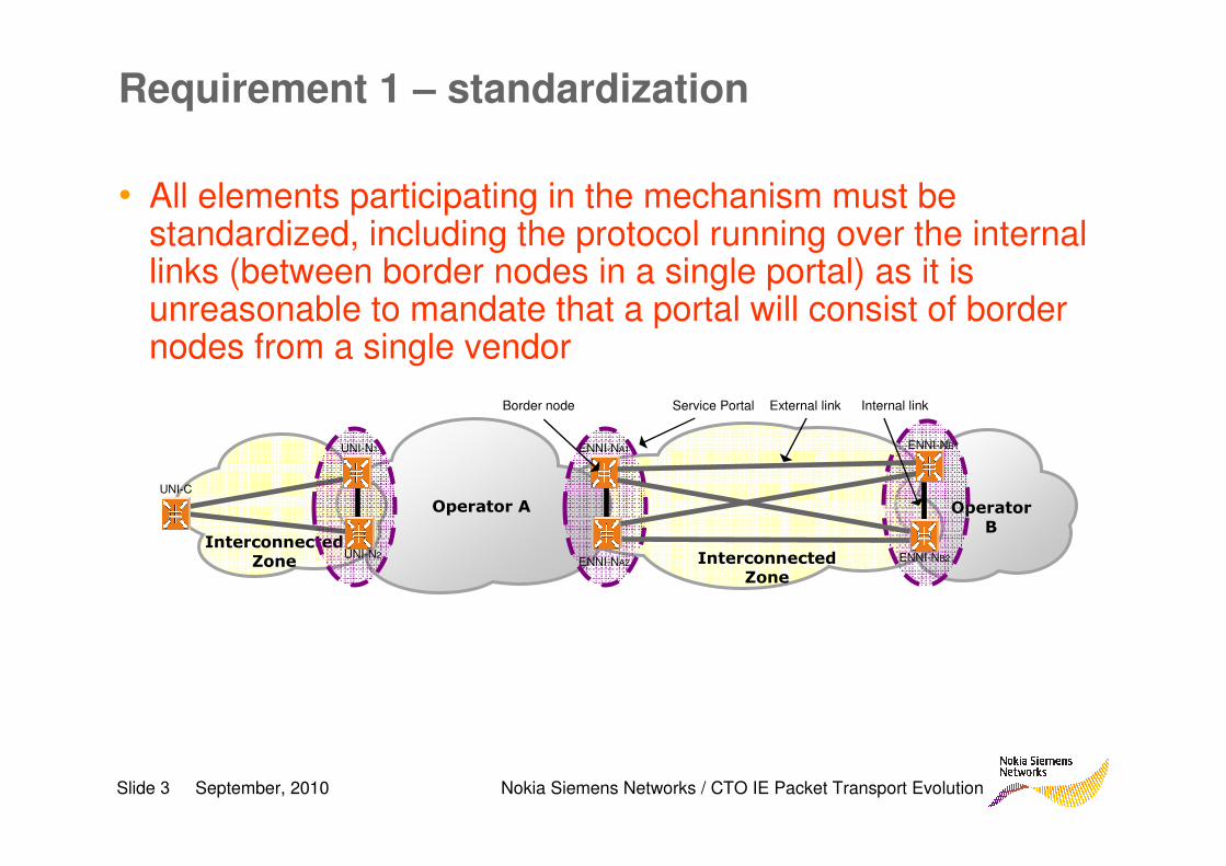
• All elements participating in the mechanism must be standardized, including the protocol running over the internal links (between border nodes in a single portal) as it is unreasonable to mandate that a portal will consist of border nodes from a single vendor
Operator
B
Interconnected Zone
Operator A
External link Internal linkBorder node Service Portal
Interconnected Zone
UNI-C
ENNI-NA1
ENNI-NA2
ENNI-NB1
ENNI-NB2
UNI-N1
UNI-N2
Slide 4 September, 2010 Nokia Siemens Networks / CTO IE Packet Transport Evolution
Requirement 1 – standardizationCause 1
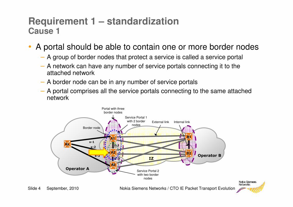
• A portal should be able to contain one or more border nodes– A group of border nodes that protect a service is called a service portal
– A network can have any number of service portals connecting it to the attached network
– A border node can be in any number of service portals
– A portal comprises all the service portals connecting to the same attached network
Operator B IZ
Operator A
External link Internal link
Border node
Service Portal 1
with 2 border nodes
B1
B2
A1
A2
Ax 1-2x-2
x-1
A3
Service Portal 2
with two border nodes
x-32-3
Portal with three border nodes
Slide 5 September, 2010 Nokia Siemens Networks / CTO IE Packet Transport Evolution
Requirement 1 – standardizationCause 2
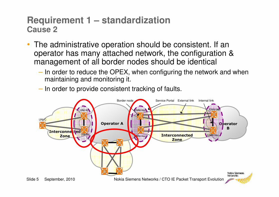
• The administrative operation should be consistent. If an operator has many attached network, the configuration & management of all border nodes should be identical
– In order to reduce the OPEX, when configuring the network and when maintaining and monitoring it.
– In order to provide consistent tracking of faults.
Operator
B
Interconnected Zone
Operator A
External link Internal linkBorder node Service Portal
Interconnected
Zone
UNI-C
ENNI-NA1
ENNI-NA2
ENNI-NB1
ENNI-NB2
UNI-N1
UNI-N2
Slide 6 September, 2010 Nokia Siemens Networks / CTO IE Packet Transport Evolution
Requirement 1 – standardizationCause 3
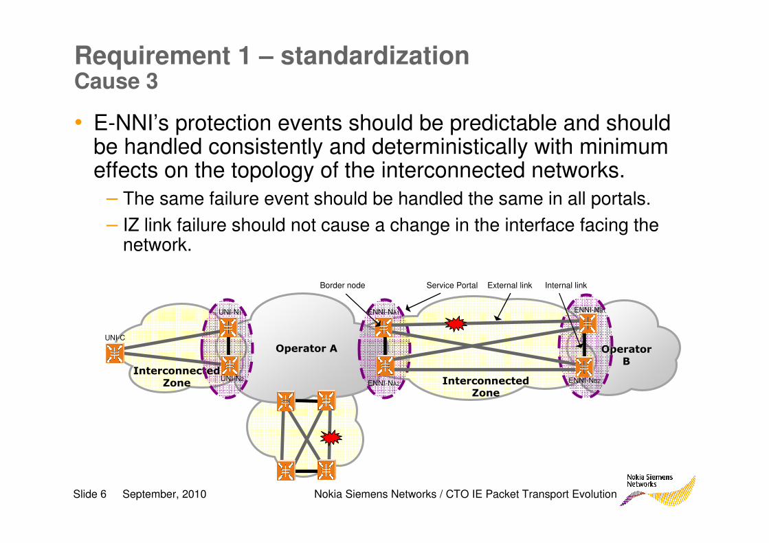
• E-NNI’s protection events should be predictable and should be handled consistently and deterministically with minimum effects on the topology of the interconnected networks.
– The same failure event should be handled the same in all portals.
– IZ link failure should not cause a change in the interface facing the network.
Operator
B
Interconnected Zone
Operator A
External link Internal linkBorder node Service Portal
Interconnected
Zone
UNI-C
ENNI-NA1
ENNI-NA2
ENNI-NB1
ENNI-NB2
UNI-N1
UNI-N2
Slide 7 September, 2010 Nokia Siemens Networks / CTO IE Packet Transport Evolution
Requirement 1 – standardizationAdditional causes
• There should not be any limitation on the products or vendors in a portal
• When a border node fails it should be possible to replace it with any standard bridge
• Replacing of border nodes from one vendor to another should be possible without interruption to services and without removing the protection
• It should be possible to replace border nodes gradually, i.e. replace one border node, see that everything is OK then replace the other border node
Slide 8 September, 2010 Nokia Siemens Networks / CTO IE Packet Transport Evolution
Requirement 2 – Technology agnosticism
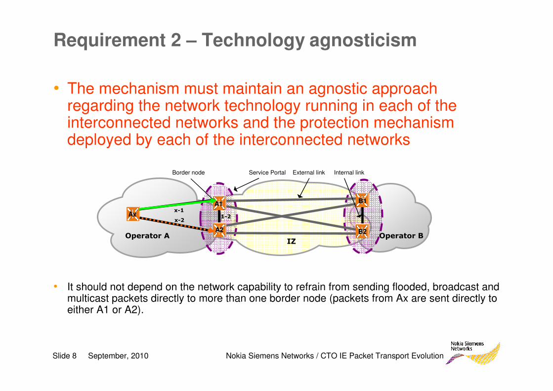
• The mechanism must maintain an agnostic approach regarding the network technology running in each of the interconnected networks and the protection mechanism deployed by each of the interconnected networks
• It should not depend on the network capability to refrain from sending flooded, broadcast and multicast packets directly to more than one border node (packets from Ax are sent directly to either A1 or A2).
Operator B IZ
Operator A
External link Internal linkBorder node Service Portal
B1
B2
A1
A2
Ax 1-2x-2
x-1
Slide 9 September, 2010 Nokia Siemens Networks / CTO IE Packet Transport Evolution
Requirement 3 – Packet duplication prevention
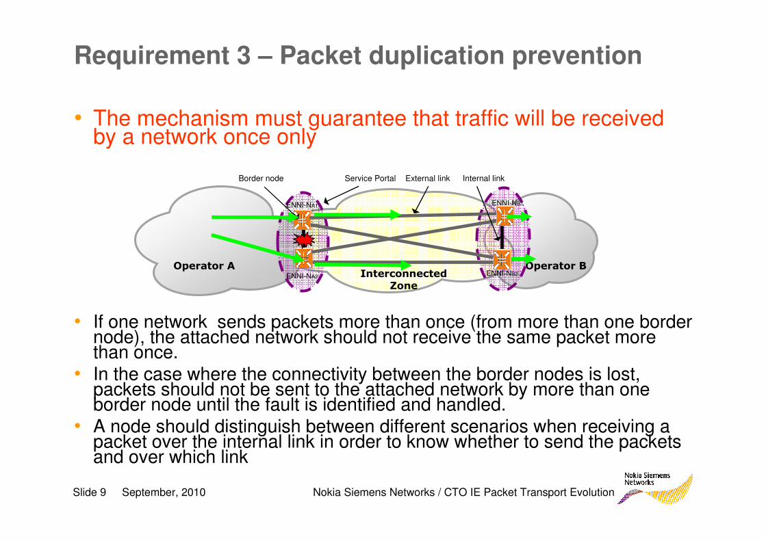
• The mechanism must guarantee that traffic will be received by a network once only
• If one network sends packets more than once (from more than one border node), the attached network should not receive the same packet more than once.
• In the case where the connectivity between the border nodes is lost, packets should not be sent to the attached network by more than one border node until the fault is identified and handled.
• A node should distinguish between different scenarios when receiving a packet over the internal link in order to know whether to send the packets and over which link
Operator B Interconnected
Zone
Operator A
External link Internal linkBorder node Service Portal
ENNI-NA1
ENNI-NA2
ENNI-NB1
ENNI-NB2
Slide 10 September, 2010 Nokia Siemens Networks / CTO IE Packet Transport Evolution
Requirement 3 – Packet duplication prevention Scenario 1
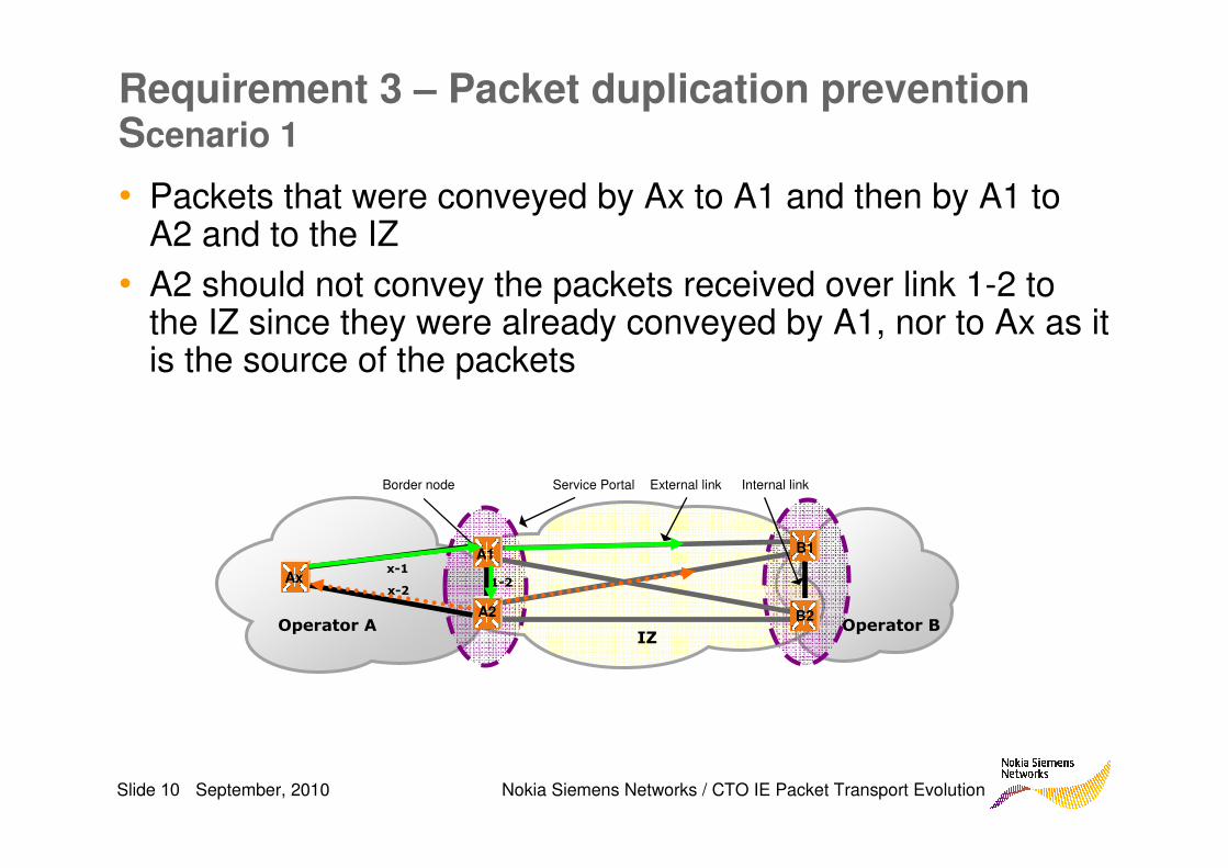
• Packets that were conveyed by Ax to A1 and then by A1 to A2 and to the IZ
• A2 should not convey the packets received over link 1-2 to the IZ since they were already conveyed by A1, nor to Ax as it is the source of the packets
Operator B IZ
Operator A
External link Internal linkBorder node Service Portal
B1
B2
A1
A2
Ax 1-2x-2
x-1
Slide 11 September, 2010 Nokia Siemens Networks / CTO IE Packet Transport Evolution
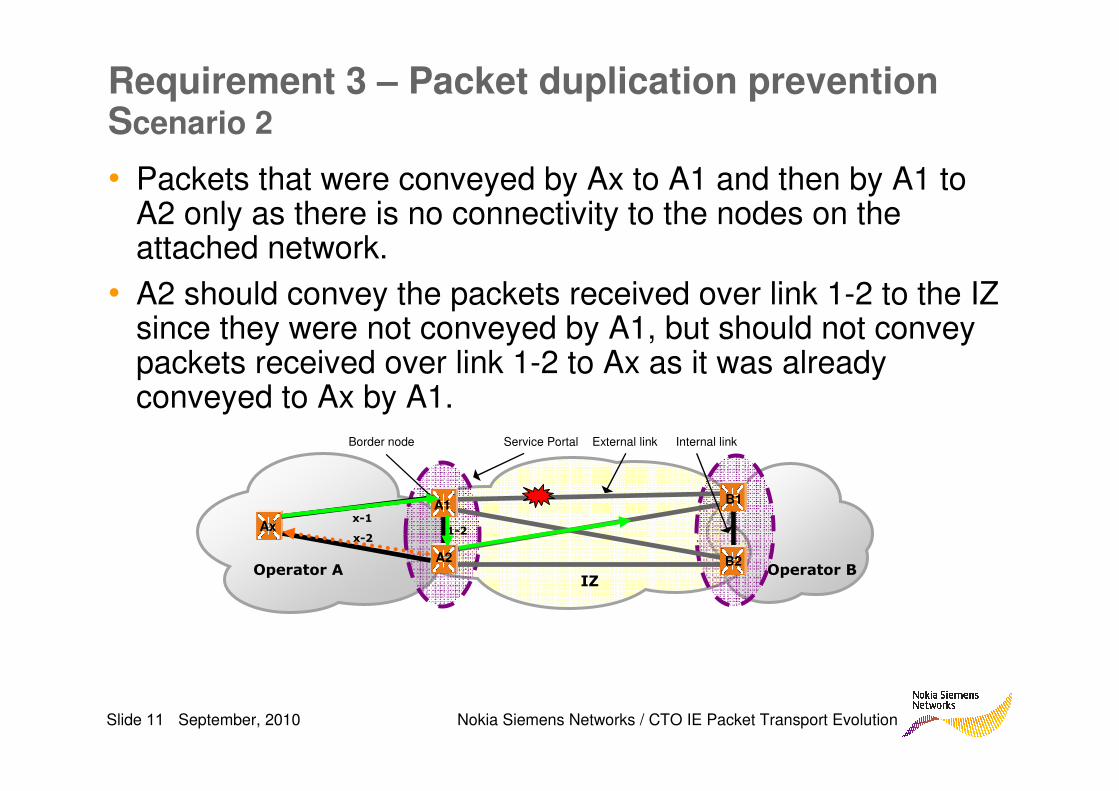
Requirement 3 – Packet duplication prevention Scenario 2
• Packets that were conveyed by Ax to A1 and then by A1 to A2 only as there is no connectivity to the nodes on the attached network.
• A2 should convey the packets received over link 1-2 to the IZ since they were not conveyed by A1, but should not convey packets received over link 1-2 to Ax as it was already conveyed to Ax by A1.
Operator B IZ
Operator A
External link Internal linkBorder node Service Portal
B1
B2
A1
A2
Ax 1-2x-2
x-1
Slide 12 September, 2010 Nokia Siemens Networks / CTO IE Packet Transport Evolution
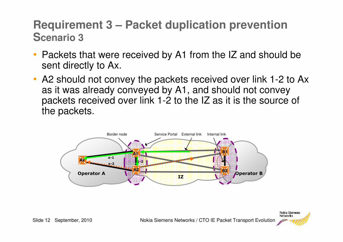
Requirement 3 – Packet duplication prevention Scenario 3
• Packets that were received by A1 from the IZ and should be sent directly to Ax.
• A2 should not convey the packets received over link 1-2 to Ax as it was already conveyed by A1, and should not convey packets received over link 1-2 to the IZ as it is the source of the packets.
Operator B IZ
Operator A
External link Internal linkBorder node Service Portal
B1
B2
A1
A2
Ax 1-2x-2
x-1
Slide 13 September, 2010 Nokia Siemens Networks / CTO IE Packet Transport Evolution
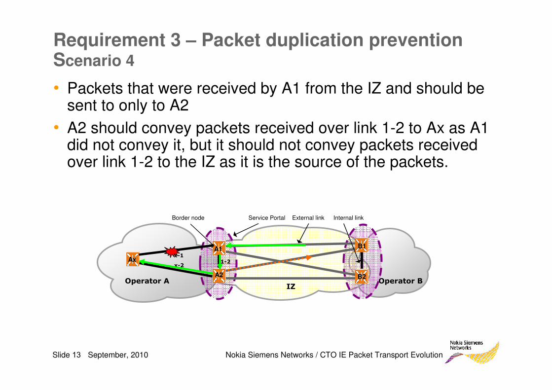
Requirement 3 – Packet duplication prevention Scenario 4
• Packets that were received by A1 from the IZ and should be sent to only to A2
• A2 should convey packets received over link 1-2 to Ax as A1 did not convey it, but it should not convey packets received over link 1-2 to the IZ as it is the source of the packets.
Operator B IZ
Operator A
External link Internal linkBorder node Service Portal
B1
B2
A1
A2
Ax 1-2x-2
x-1
Slide 14 September, 2010 Nokia Siemens Networks / CTO IE Packet Transport Evolution
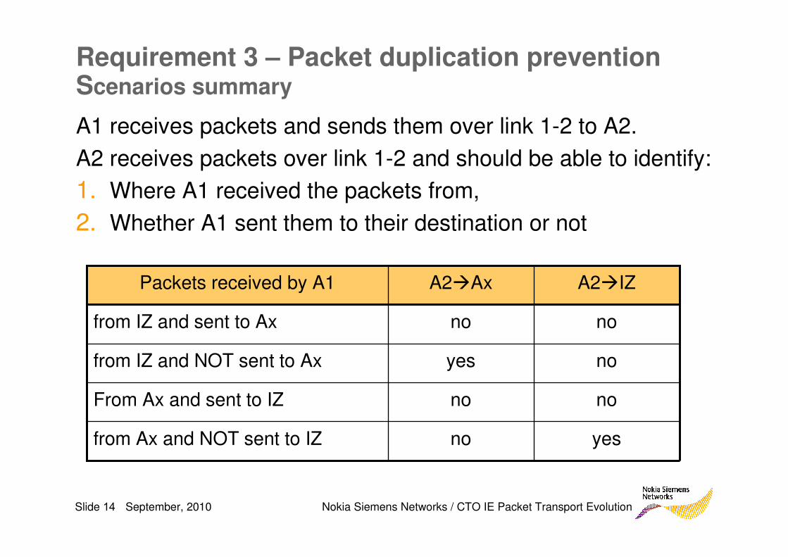
Requirement 3 – Packet duplication prevention Scenarios summary
no
no
yes
no
A2�Ax
yesfrom Ax and NOT sent to IZ
noFrom Ax and sent to IZ
nofrom IZ and NOT sent to Ax
nofrom IZ and sent to Ax
A2�IZPackets received by A1
A1 receives packets and sends them over link 1-2 to A2.
A2 receives packets over link 1-2 and should be able to identify:
1. Where A1 received the packets from,
2. Whether A1 sent them to their destination or not
Slide 15 September, 2010 Nokia Siemens Networks / CTO IE Packet Transport Evolution
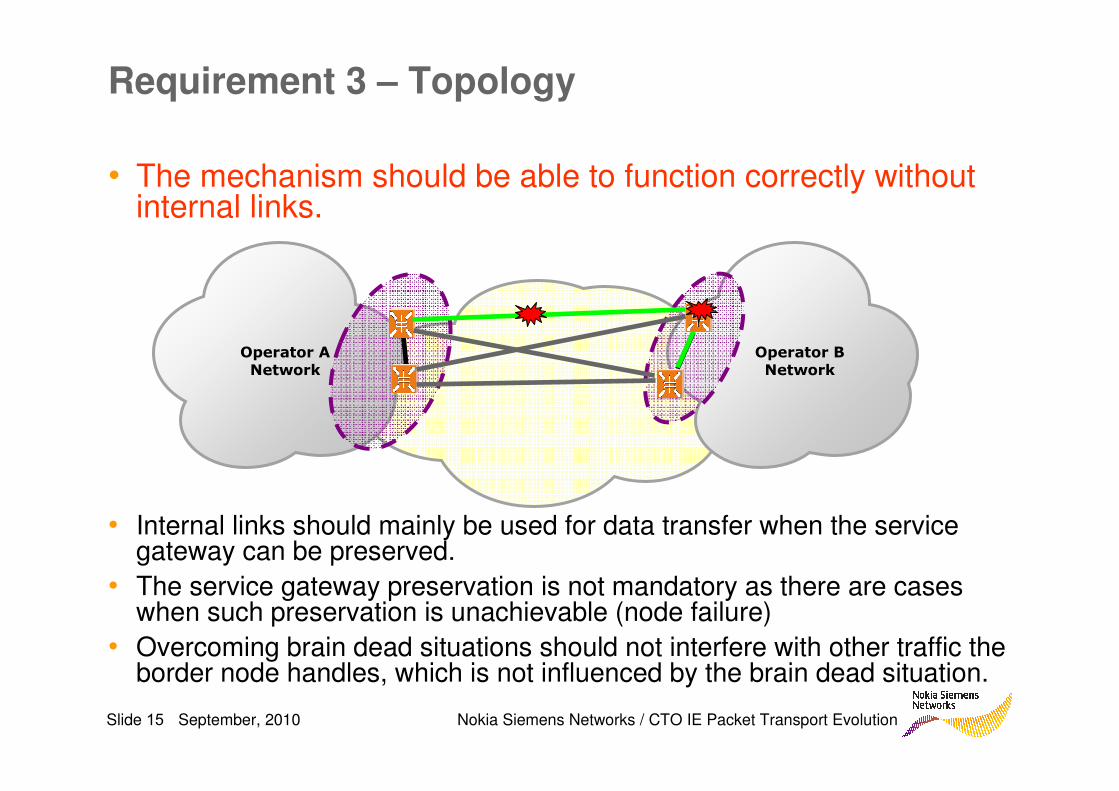
Requirement 3 – Topology
• The mechanism should be able to function correctly without internal links.
• Internal links should mainly be used for data transfer when the service gateway can be preserved.
• The service gateway preservation is not mandatory as there are cases when such preservation is unachievable (node failure)
• Overcoming brain dead situations should not interfere with other traffic the border node handles, which is not influenced by the brain dead situation.
Operator B
Network
Operator A
Network