Embed Size (px)
Citation preview
NMR SPECTROSCOPY
1
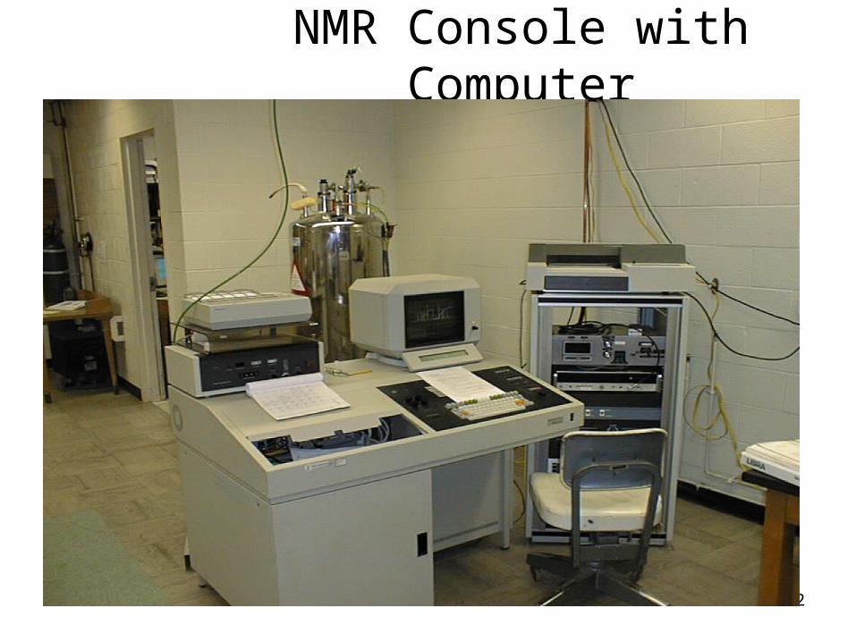
NMR Console with Computer
2
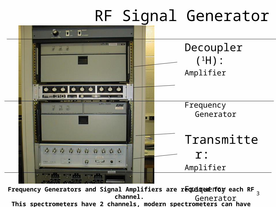
RF Signal Generator
Decoupler (1H):Amplifier
Frequency Generator
Transmitter:Amplifier
Frequency Generator
3Frequency Generators and Signal Amplifiers are required for each RF channel. This spectrometers have 2 channels, modern spectrometers can have up to 8
channels.
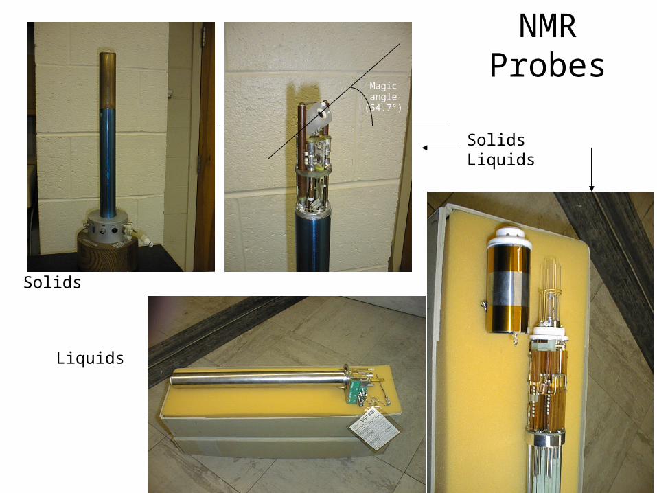
NMR Probes
4
Solids Liquids
Solids
Liquids
Magic angle(54.7°)
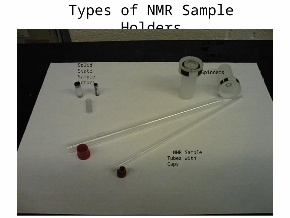
Types of NMR Sample Holders
5
Solid State Sample Rotors
Solution NMR Sample Tube Spinners
NMR Sample Tubes with Caps
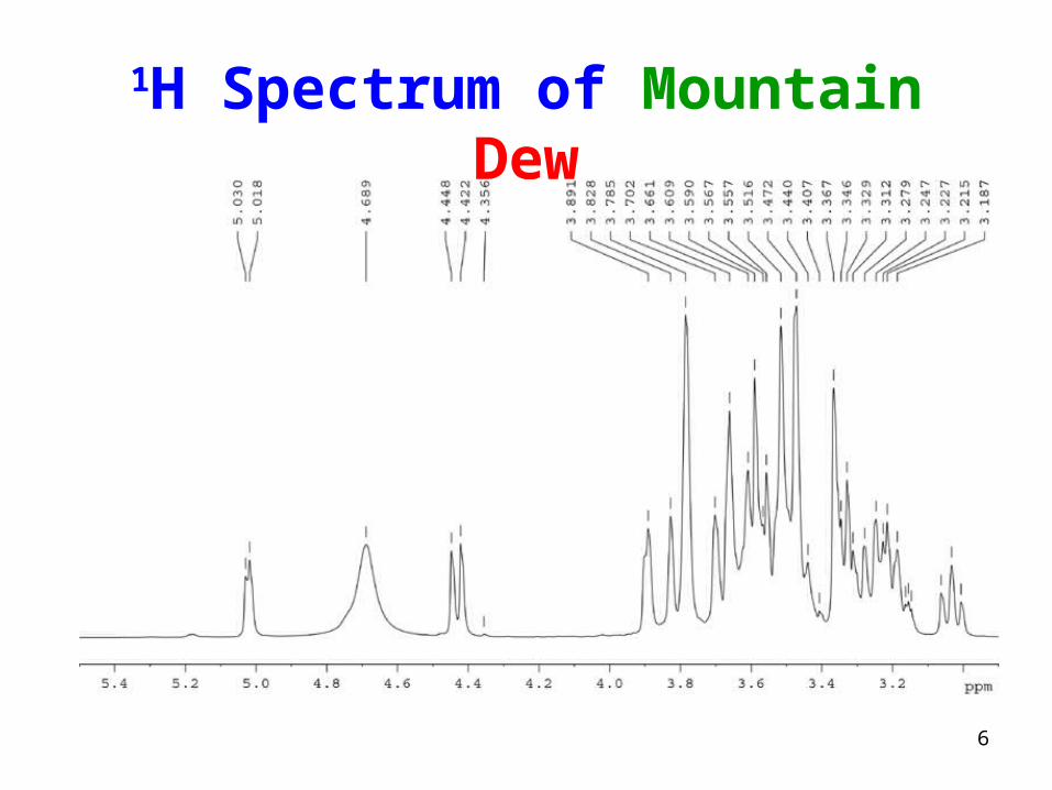
1H Spectrum of Mountain Dew
6
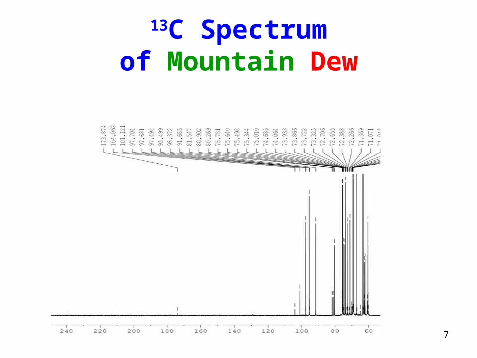
13C Spectrumof Mountain Dew
7
What is NMR?
8

NMR Stands for:
• NUCLEAR
• MAGNETIC
• RESONANCE
9
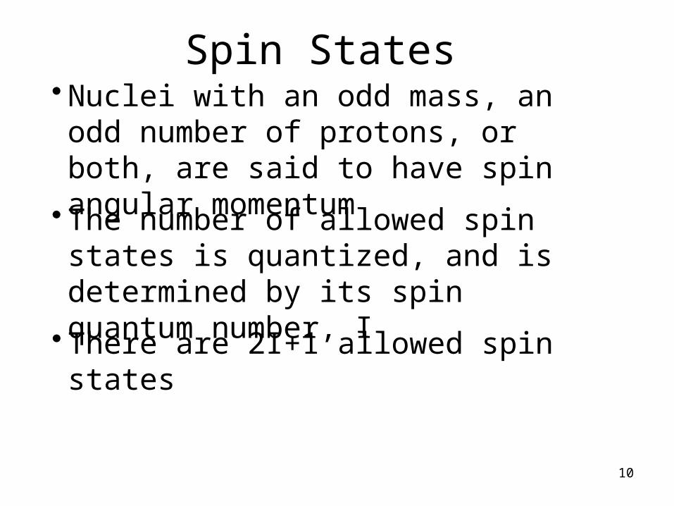
Spin States• Nuclei with an odd mass, an odd number of protons, or both, are said to have spin angular momentum
• The number of allowed spin states is quantized, and is determined by its spin quantum number, I
• There are 2I+1 allowed spin states
10
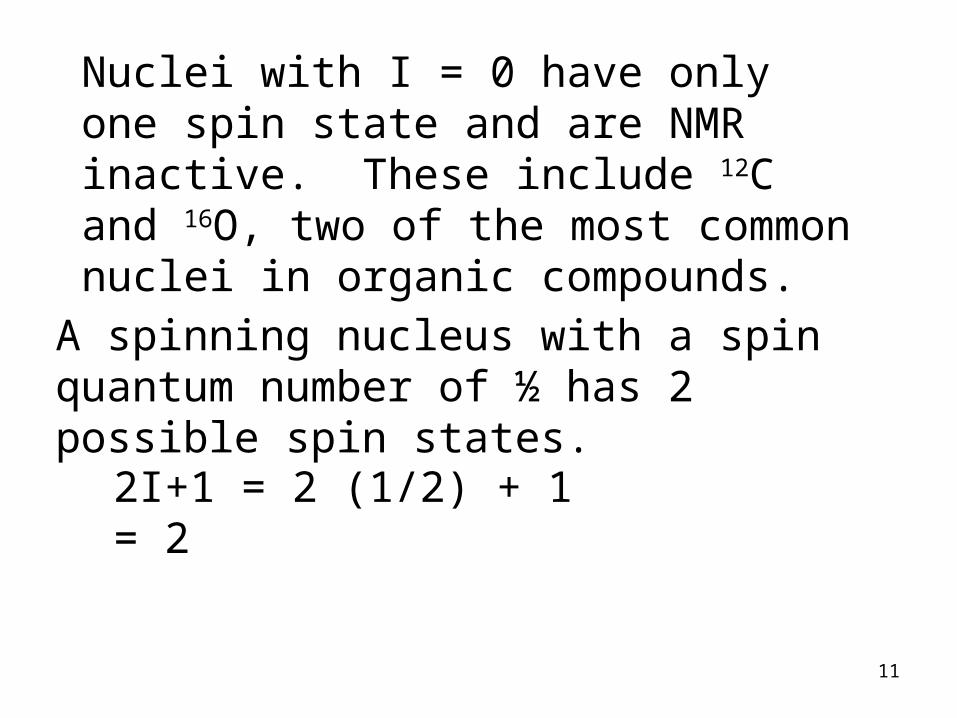
A spinning nucleus with a spin quantum number of ½ has 2 possible spin states.
2I+1 = 2 (1/2) + 1 = 2
Nuclei with I = 0 have only one spin state and are NMR inactive. These include 12C and 16O, two of the most common nuclei in organic compounds.
11

The Most Interesting Elements (to us) All Have 2 Allowed Spin States
These are• 1H• 13C• 19F• 31P
Deuterium 2H is spin active with I = 1!
2 (1) + 1 = 3 spin states for deuterium12
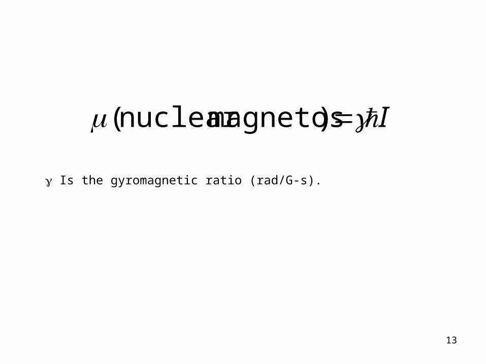
I )magnetosnuclear (
Is the gyromagnetic ratio (rad/G-s).
13
14
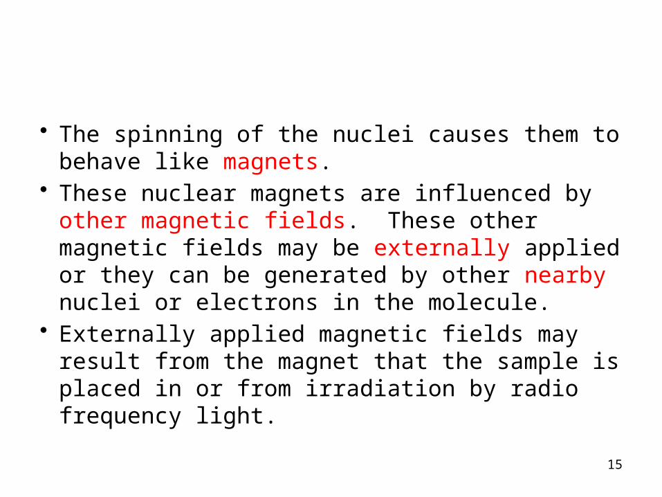
• The spinning of the nuclei causes them to behave like magnets.
• These nuclear magnets are influenced by other magnetic fields. These other magnetic fields may be externally applied or they can be generated by other nearby nuclei or electrons in the molecule.
• Externally applied magnetic fields may result from the magnet that the sample is placed in or from irradiation by radio frequency light.
15
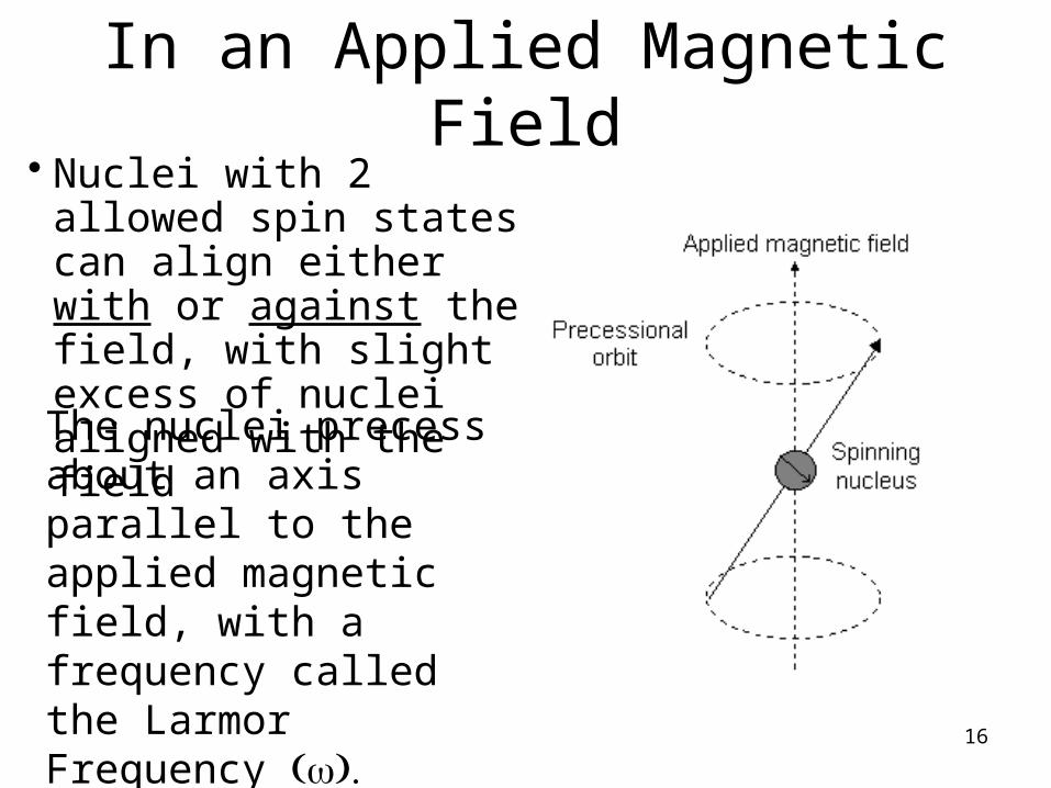
In an Applied Magnetic Field• Nuclei with 2 allowed spin
states can align either with or against the field, with slight excess of nuclei aligned with the fieldThe nuclei precess about an axis parallel to the applied magnetic field, with a frequency called the Larmor Frequency ( ).w
16
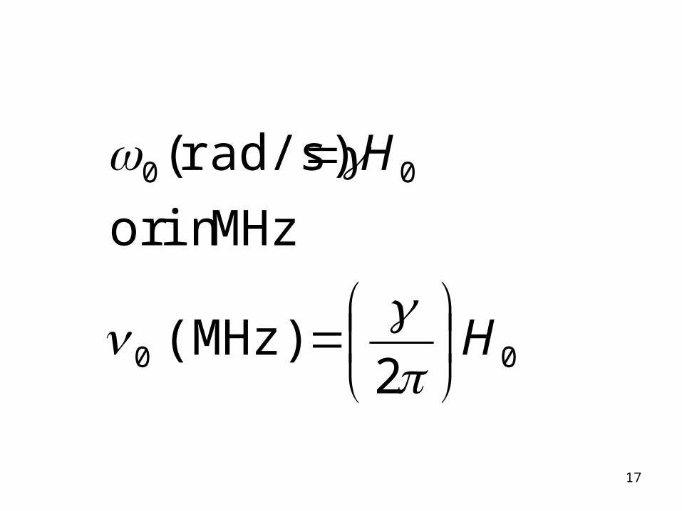
00
00
2(MHz)
MHzin or
rad/s)(
H
H
17
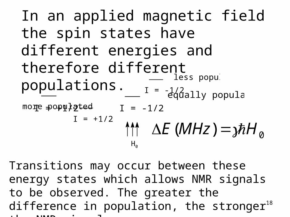
I = -1/2
I = +1/2
more populated
less populated
Bo
I = +1/2 I = -1/2
equally populated
In an applied magnetic field the spin states have different energies and therefore different populations.
Transitions may occur between these energy states which allows NMR signals to be observed. The greater the difference in population, the stronger the NMR signal.
18
0)( HMHzE H0
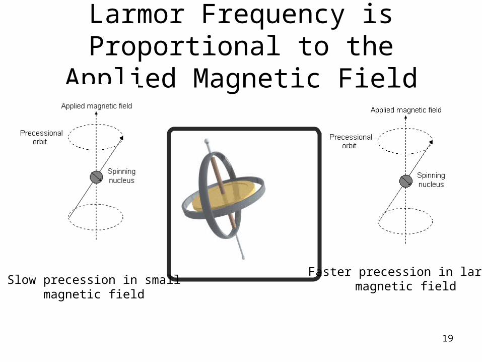
Larmor Frequency is Proportional to the Applied Magnetic Field
Slow precession in smallmagnetic field
Faster precession in largermagnetic field
19

The difference in energy between the 2 spin states is proportional to the Larmor frequency
20
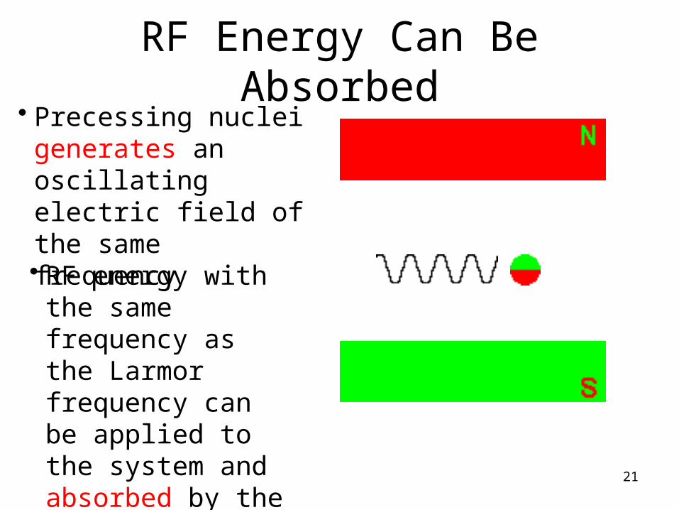
RF Energy Can Be Absorbed• Precessing nuclei
generates an oscillating electric field of the same frequency
• RF energy with the same frequency as the Larmor frequency can be applied to the system and absorbed by the nuclei
21
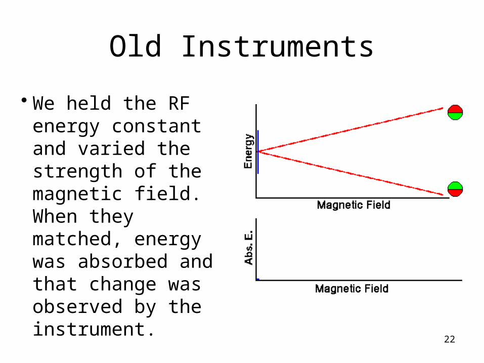
Old Instruments
• We held the RF energy constant and varied the strength of the magnetic field. When they matched, energy was absorbed and that change was observed by the instrument.
22
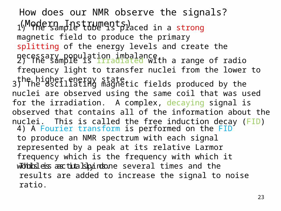
How does our NMR observe the signals? (Modern Instruments)
1) The sample tube is placed in a strong magnetic field to produce the primary splitting of the energy levels and create the necessary population imbalance.
2) The sample is irradiated with a range of radio frequency light to transfer nuclei from the lower to the higher energy state.
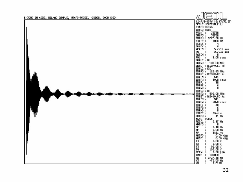
3) The oscillating magnetic fields produced by the nuclei are observed using the same coil that was used for the irradiation. A complex, decaying signal is observed that contains all of the information about the nuclei. This is called the free induction decay (FID)
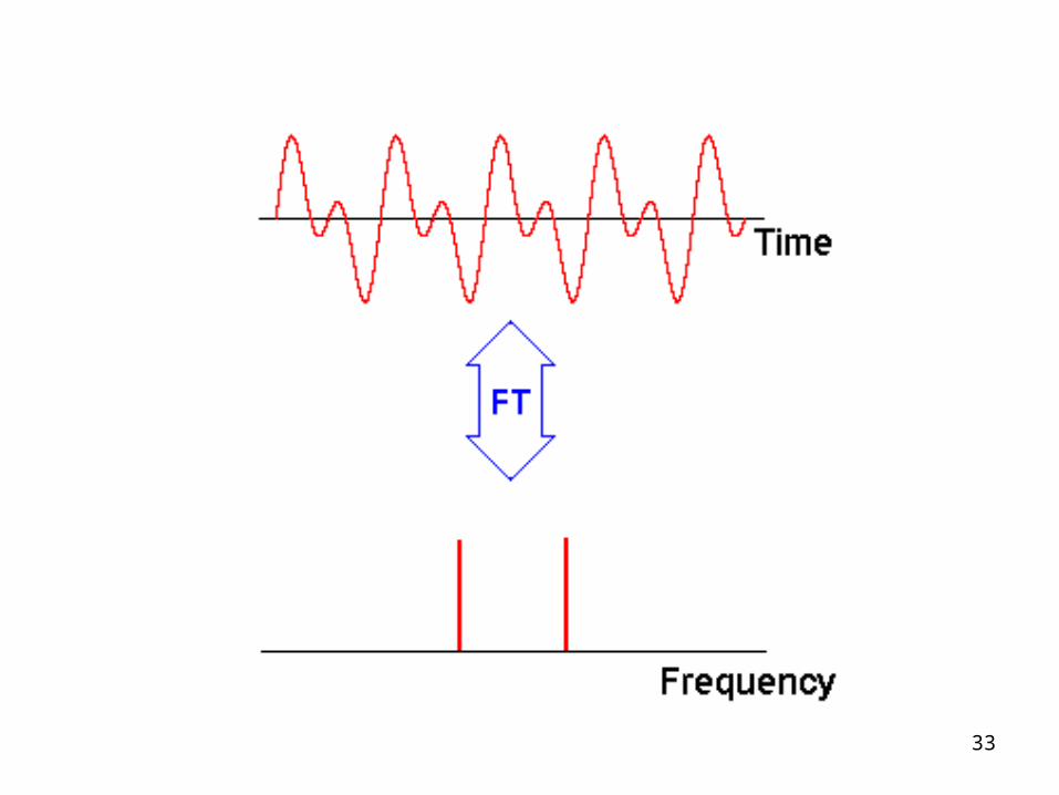
4) A Fourier transform is performed on the FID to produce an NMR spectrum with each signal represented by a peak at its relative Larmor frequency which is the frequency with which it wobbles as it spins.
This is actually done several times and the results are added to increase the signal to noise ratio.
23
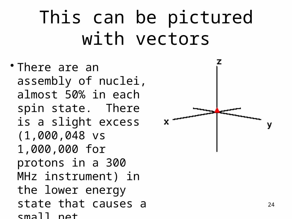
This can be pictured with vectors
24
• There are an assembly of nuclei, almost 50% in each spin state. There is a slight excess (1,000,048 vs 1,000,000 for protons in a 300 MHz instrument) in the lower energy state that causes a small net magnetization in the z direction.

How Does this Happen in the Instrument?
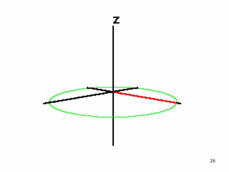
Red arrow represents net magnetization (there is an excess in the lowspin state. The applied Rf energy causes the net magnetization for all typesof the nuclei to tip to the x-y plane (90 degree pulse). It should be noted that all nuclei of a given type are in synch with one another.
25
26
Nuclei relax back to their original state, emitting electromagnetic radiation at their original Larmor frequencies
The data we get can be complex: it is a superimposed combination of all the frequencies (Note: this is the difference between the applied frequency and the Larmor frequencies of the nuclei.
27
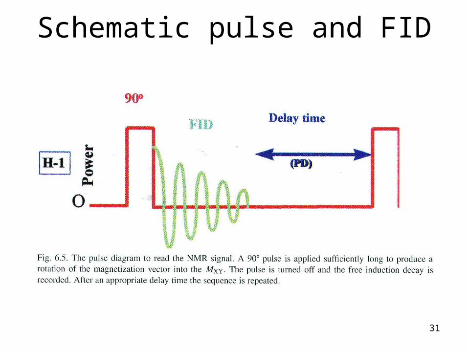
Schematic pulse and FID
31
32
33