Embed Size (px)
Citation preview
ETSI TS 125 321 V5.2.0 (2002-09)
Technical Specification
Universal Mobile Telecommunications System (UMTS);Medium Access Control (MAC) protocol specification
(3GPP TS 25.321 version 5.2.0 Release 5)
ETSI
ETSI TS 125 321 V5.2.0 (2002-09) 1 3GPP TS 25.321 version 5.2.0 Release 5
Reference RTS/TSGR-0225321v520
Keywords UMTS
ETSI
650 Route des Lucioles F-06921 Sophia Antipolis Cedex - FRANCE
Tel.: +33 4 92 94 42 00 Fax: +33 4 93 65 47 16
Siret N° 348 623 562 00017 - NAF 742 C
Association à but non lucratif enregistrée à la Sous-Préfecture de Grasse (06) N° 7803/88
Important notice
Individual copies of the present document can be downloaded from: http://www.etsi.org
The present document may be made available in more than one electronic version or in print. In any case of existing or perceived difference in contents between such versions, the reference version is the Portable Document Format (PDF).
In case of dispute, the reference shall be the printing on ETSI printers of the PDF version kept on a specific network drive within ETSI Secretariat.
Users of the present document should be aware that the document may be subject to revision or change of status. Information on the current status of this and other ETSI documents is available at
http://portal.etsi.org/tb/status/status.asp
If you find errors in the present document, send your comment to: [email protected]
Copyright Notification
No part may be reproduced except as authorized by written permission. The copyright and the foregoing restriction extend to reproduction in all media.
© European Telecommunications Standards Institute 2002.
All rights reserved.
DECTTM, PLUGTESTSTM and UMTSTM are Trade Marks of ETSI registered for the benefit of its Members. TIPHONTM and the TIPHON logo are Trade Marks currently being registered by ETSI for the benefit of its Members. 3GPPTM is a Trade Mark of ETSI registered for the benefit of its Members and of the 3GPP Organizational Partners.
ETSI
ETSI TS 125 321 V5.2.0 (2002-09) 2 3GPP TS 25.321 version 5.2.0 Release 5
Intellectual Property Rights IPRs essential or potentially essential to the present document may have been declared to ETSI. The information pertaining to these essential IPRs, if any, is publicly available for ETSI members and non-members, and can be found in ETSI SR 000 314: "Intellectual Property Rights (IPRs); Essential, or potentially Essential, IPRs notified to ETSI in respect of ETSI standards", which is available from the ETSI Secretariat. Latest updates are available on the ETSI Web server (http://webapp.etsi.org/IPR/home.asp).
Pursuant to the ETSI IPR Policy, no investigation, including IPR searches, has been carried out by ETSI. No guarantee can be given as to the existence of other IPRs not referenced in ETSI SR 000 314 (or the updates on the ETSI Web server) which are, or may be, or may become, essential to the present document.
Foreword This Technical Specification (TS) has been produced by ETSI 3rd Generation Partnership Project (3GPP).
The present document may refer to technical specifications or reports using their 3GPP identities, UMTS identities or GSM identities. These should be interpreted as being references to the corresponding ETSI deliverables.
The cross reference between GSM, UMTS, 3GPP and ETSI identities can be found under www.etsi.org/key .
ETSI
ETSI TS 125 321 V5.2.0 (2002-09) 3 3GPP TS 25.321 version 5.2.0 Release 5
Contents
Intellectual Property Rights ................................................................................................................................2
Foreword.............................................................................................................................................................2
Foreword.............................................................................................................................................................5
1 Scope ........................................................................................................................................................6
2 References ................................................................................................................................................6
3 Definitions and abbreviations...................................................................................................................7 3.1 Definitions..........................................................................................................................................................7 3.2 Abbreviations .....................................................................................................................................................7
4 General .....................................................................................................................................................8 4.1 Objective ............................................................................................................................................................8 4.2 MAC architecture ...............................................................................................................................................8 4.2.1 MAC Entities ................................................................................................................................................8 4.2.2 MAC-b..........................................................................................................................................................8 4.2.3 Traffic Related Architecture - UE Side.........................................................................................................9 4.2.3.1 MAC-c/sh entity – UE Side ..................................................................................................................10 4.2.3.2 MAC-d entity – UE Side.......................................................................................................................11 4.2.3.3 MAC-hs entity – UE Side .....................................................................................................................12 4.2.4 Traffic Related Architecture - UTRAN Side ..............................................................................................13 4.2.4.1 MAC-c/sh entity – UTRAN Side ..........................................................................................................14 4.2.4.2 MAC-d entity – UTRAN Side ..............................................................................................................15 4.2.4.3 MAC-hs entity – UTRAN Side.............................................................................................................16 4.3 Channel structure..............................................................................................................................................17 4.3.1 Transport channels......................................................................................................................................17 4.3.2 Logical Channels ........................................................................................................................................18 4.3.2.1 Logical channel structure ......................................................................................................................18 4.3.2.2 Control Channels...................................................................................................................................18 4.3.2.3 Traffic Channels....................................................................................................................................19
5 Services provided to upper layers ..........................................................................................................19 5.1 Description of Services provided to upper layers.............................................................................................19
6 Functions ................................................................................................................................................19 6.1 Description of the MAC functions ...................................................................................................................19 6.2 Relation between MAC Functions and Transport Channels ............................................................................20 6.2.1 Relation between MAC Functions and Transport Channels in UTRAN ....................................................20 6.2.2 Relation of MAC Functions and Transport Channels in UE ......................................................................21
7 Services expected from physical layer ...................................................................................................21
8 Elements for layer-to-layer communication...........................................................................................21 8.1 Primitives between layers 1 and 2 ....................................................................................................................21 8.1.1 Primitives....................................................................................................................................................21 8.1.2 Parameters...................................................................................................................................................22 8.2 Primitives between MAC and RLC..................................................................................................................22 8.2.1 Primitives....................................................................................................................................................22 8.2.2 Parameters...................................................................................................................................................22 8.3 Primitives between MAC and RRC .................................................................................................................23 8.3.1 Primitives....................................................................................................................................................23 8.3.2 Parameters...................................................................................................................................................24
9 Elements for peer-to-peer communication .............................................................................................25 9.1 Protocol data units ............................................................................................................................................25 9.1.1 General........................................................................................................................................................25 9.1.2 MAC PDU (non-HS-DSCH) ......................................................................................................................25 9.1.3 MAC-d PDU (HS-DSCH) ..........................................................................................................................26
ETSI
ETSI TS 125 321 V5.2.0 (2002-09) 4 3GPP TS 25.321 version 5.2.0 Release 5
9.1.4 MAC PDU (HS-DSCH)..............................................................................................................................26 9.2 Formats and parameters....................................................................................................................................26 9.2.1 MAC PDU: Parameters of the MAC PDU header (non HS-DSCH) and MAC-d PDU header (HS-
DSCH) ........................................................................................................................................................26 9.2.1.1 MAC header for DTCH and DCCH (not mapped on HS-DSCH) ........................................................29 9.2.1.1a MAC-d Header for DTCH and DCCH (mapped on HS-DSCH) ..........................................................30 9.2.1.2 MAC header for BCCH ........................................................................................................................30 9.2.1.3 MAC header for PCCH.........................................................................................................................30 9.2.1.4 MAC header for CCCH ........................................................................................................................30 9.2.1.5 MAC Header for CTCH........................................................................................................................30 9.2.1.6 MAC Header for SHCCH .....................................................................................................................30 9.2.2 MAC PDU: Parameters of the MAC header (HS-DSCH) ..........................................................................31 9.2.2.1 MAC header for DTCH and DCCH......................................................................................................31 9.2.3 Signalling of Transport Block size for HS-DSCH......................................................................................31 9.2.3.1 Transport block size for FDD................................................................................................................31 9.2.3.2 Transport block size for 3.84 Mcps TDD..............................................................................................33 9.2.3.3 Transport block size for 1.28 Mcps TDD..............................................................................................33
10 Handling of unknown, unforeseen and erroneous protocol data ............................................................33
11 Specific functions...................................................................................................................................34 11.1 Traffic volume measurement for dynamic radio bearer control .......................................................................34 11.2 Control of RACH transmissions.......................................................................................................................34 11.2.1 Access Service Class selection ...................................................................................................................35 11.2.2 Control of RACH transmissions for FDD mode.........................................................................................35 11.2.3 Control of RACH transmissions for TDD ..................................................................................................38 11.2.3.1 Control of RACH transmissions for 3.84 Mcps TDD...........................................................................38 11.2.3.2 Control of RACH Transmissions for 1.28 Mcps TDD..........................................................................39 11.3 Control of CPCH transmissions for FDD.........................................................................................................41 11.4 Transport format combination selection in UE ................................................................................................45 11.5 Ciphering..........................................................................................................................................................47 11.6 Control of HS-DSCH transmission and reception............................................................................................47 11.6.1 Network operation ......................................................................................................................................47 11.6.1.1 Scheduler...............................................................................................................................................47 11.6.1.2 HARQ entity .........................................................................................................................................48 11.6.1.3 HARQ process ......................................................................................................................................48 11.6.2 UE operation...............................................................................................................................................48 11.6.2.1 HARQ Entity.........................................................................................................................................48 11.6.2.2 HARQ process ......................................................................................................................................49 11.6.2.3 Reordering entity...................................................................................................................................49 11.6.2.3.1 Definitions .......................................................................................................................................49 11.6.2.4 Disassembly entity ................................................................................................................................51 11.6.2.5 MAC-hs Reset.......................................................................................................................................51
Annex A (informative): Change history ...............................................................................................52
History ..............................................................................................................................................................54
ETSI
ETSI TS 125 321 V5.2.0 (2002-09) 5 3GPP TS 25.321 version 5.2.0 Release 5
Foreword This Technical Specification (TS) has been produced by the 3rd Generation Partnership Project (3GPP).
The contents of the present document are subject to continuing work within the TSG and may change following formal TSG approval. Should the TSG modify the contents of the present document, it will be re-released by the TSG with an identifying change of release date and an increase in version number as follows:
Version x.y.z
where:
x the first digit:
1 presented to TSG for information;
2 presented to TSG for approval;
3 or greater indicates TSG approved document under change control.
y the second digit is incremented for all changes of substance, i.e. technical enhancements, corrections, updates, etc.
z the third digit is incremented when editorial only changes have been incorporated in the document.
ETSI
ETSI TS 125 321 V5.2.0 (2002-09) 6 3GPP TS 25.321 version 5.2.0 Release 5
1 Scope The present document specifies the MAC protocol.
The specification describes:
- MAC architecture;
- MAC entities;
- channel structure;
- services provided to upper layers;
- MAC functions;
- services expected from the physical layer;
- elements for layer-to-layer communication including primitives between MAC and RLC;
- elements for peer-to-peer communication;
- protocol data units, formats and parameters;
- elementary procedures.
2 References The following documents contain provisions which, through reference in this text, constitute provisions of the present document.
• References are either specific (identified by date of publication, edition number, version number, etc.) or non-specific.
• For a specific reference, subsequent revisions do not apply.
• For a non-specific reference, the latest version applies. In the case of a reference to a 3GPP document (including a GSM document), a non-specific reference implicitly refers to the latest version of that document in the same Release as the present document.
[1] 3GPP TR 21.905: "Vocabulary for 3GPP Specifications".
[2] 3GPP TS 25.301: "Radio Interface Protocol Architecture".
[3] 3GPP TS 25.302: "Services provided by the Physical Layer".
[4] 3GPP TS 25.303: "Interlayer Procedures in Connected Mode".
[5] 3GPP TS 25.304: "UE Procedures in Idle Mode and Procedures for Cell Reselection in Connected Mode".
[6] 3GPP TS 25.322: "RLC Protocol Specification".
[7] 3GPP TS 25.331: "Radio Resource Control (RRC); protocol specification".
[8] 3GPP TR 25.921: "Guidelines and Principles for Protocol Description and Error Handling".
[9] 3GPP TR 25.990: "Vocabulary for the UTRAN".
[10] 3GPP TS 33.102: "Security architecture".
[11] 3GPP TS 25.425: "UTRAN Iur Interface User Plane Protocols for Common Transport Channel Data Streams".
ETSI
ETSI TS 125 321 V5.2.0 (2002-09) 7 3GPP TS 25.321 version 5.2.0 Release 5
[12] 3GPP TS 25.133: "Requirements for support of radio resource management (FDD)".
[13] 3GPP TS 25.214: "Physical layer procedures (FDD)".
[14] 3GPP TS 25.123: "Requirements for support of radio resource management (TDD)".
3 Definitions and abbreviations
3.1 Definitions For the purposes of the present document, the terms and definitions given in [9] and [1] apply.
3.2 Abbreviations For the purposes of the present document, the following abbreviations apply:
ASC Access Service Class BCCH Broadcast Control Channel BCH Broadcast Channel C- Control- CCCH Common Control Channel CPCH Common Packet Channel (UL) DCCH Dedicated Control Channel DCH Dedicated Channel DL Downlink DSCH Downlink Shared Channel DTCH Dedicated Traffic Channel FACH Forward Link Access Channel FDD Frequency Division Duplex HARQ Hybrid Automatic Repeat Request HS-DSCH High Speed Downlink Shared Channel L1 Layer 1 (physical layer) L2 Layer 2 (data link layer) L3 Layer 3 (network layer) MAC Medium Access Control PCCH Paging Control Channel PCH Paging Channel PDU Protocol Data Unit PHY Physical layer PhyCH Physical Channels RACH Random Access Channel RLC Radio Link Control RNC Radio Network Controller RNS Radio Network Subsystem RNTI Radio Network Temporary Identity RRC Radio Resource Control SAP Service Access Point SDU Service Data Unit SHCCH Shared Channel Control Channel SRNC Serving Radio Network Controller SRNS Serving Radio Network Subsystem TDD Time Division Duplex TFCI Transport Format Combination Indicator TFI Transport Format Indicator TSN Transmission Sequence Number U- User- UE User Equipment UL Uplink
ETSI
ETSI TS 125 321 V5.2.0 (2002-09) 8 3GPP TS 25.321 version 5.2.0 Release 5
UMTS Universal Mobile Telecommunications System USCH Uplink Shared Channel UTRA UMTS Terrestrial Radio Access UTRAN UMTS Terrestrial Radio Access Network
4 General
4.1 Objective The objective is to describe the MAC architecture and the different MAC entities from a functional point of view.
4.2 MAC architecture The description in this subclause is a model and does not specify or restrict implementations.
According to the RRC functions the RRC is generally in control of the internal configuration of the MAC.
4.2.1 MAC Entities
The diagrams that describe the MAC architecture are constructed from MAC entities.
The entities are assigned the following names.
- MAC-b is the MAC entity that handles the following transport channels:
- broadcast channel (BCH)
- MAC-c/sh, is the MAC entity that handles the following transport channels:
- paging channel (PCH)
- forward access channel (FACH)
- random access channel (RACH)
- common packet channel (UL CPCH). The CPCH exists only in FDD mode.
- downlink shared channel (DSCH)
- uplink shared channel (USCH). The USCH exists only in TDD mode.
- MAC-d is the MAC entity that handles the following transport channels:
- dedicated transport channel (DCH)
- MAC-hs is the MAC entity that handles the following transport channels:
- high speed downlink shared channel (HS-DSCH)
The exact functions completed by the entities are different in the UE from those completed in the UTRAN.
NOTE: When a UE is allocated resources for exclusive use by the bearers that it supports the MAC-d entities dynamically share the resources between the bearers and are responsible for selecting the TFI/ TFCI that is to be used in each transmission time interval.
4.2.2 MAC-b
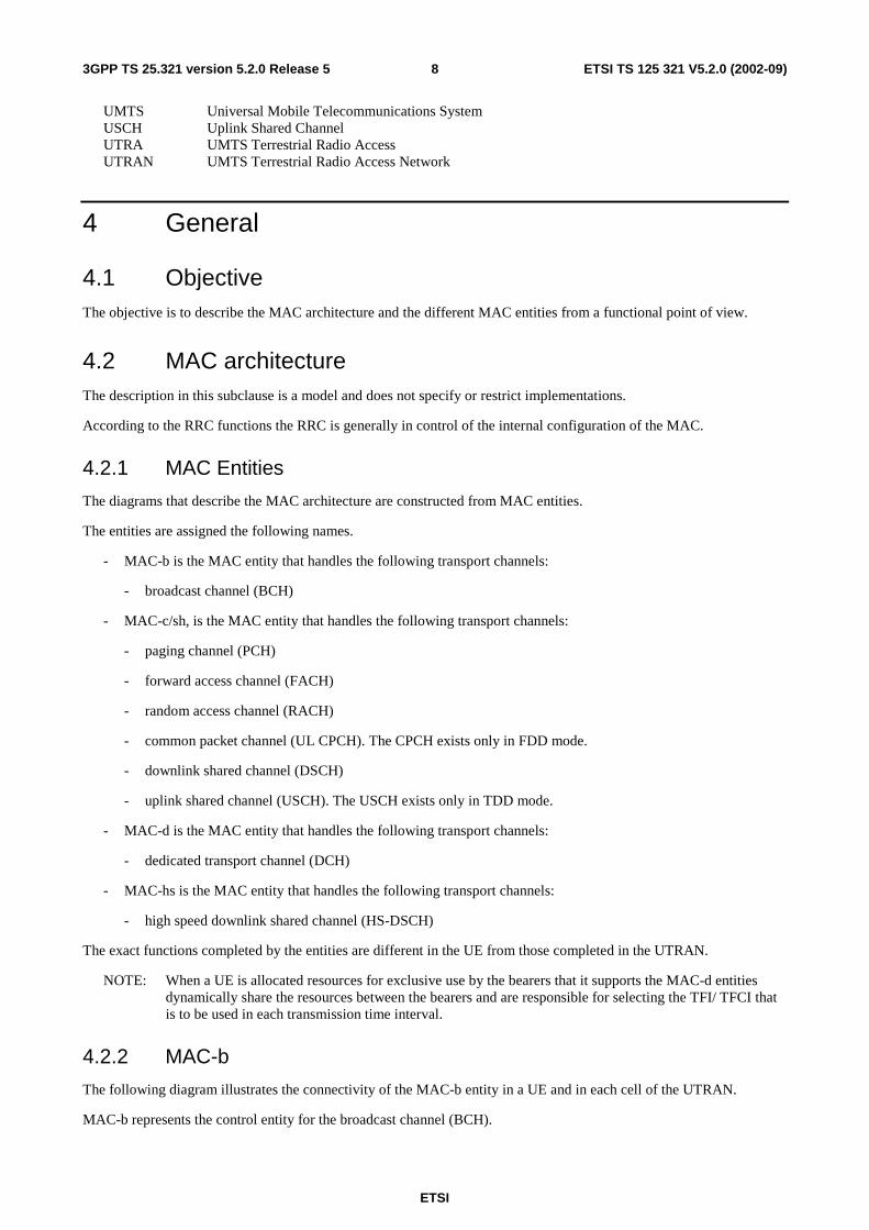
The following diagram illustrates the connectivity of the MAC-b entity in a UE and in each cell of the UTRAN.
MAC-b represents the control entity for the broadcast channel (BCH).
ETSI
ETSI TS 125 321 V5.2.0 (2002-09) 9 3GPP TS 25.321 version 5.2.0 Release 5
There is one (current cell) or multiple (current and neighbour cells) MAC-b entities in each UE and one MAC-b in the UTRAN for each cell.
The MAC Control SAP is used to transfer Control information to MAC-b.
The MAC-b entity is located in the Node B.
MAC-b
BCCH
BCH
Mac Control
Figure 4.2.2.1: UE side and UTRAN side architecture
4.2.3 Traffic Related Architecture - UE Side
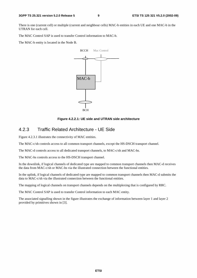
Figure 4.2.3.1 illustrates the connectivity of MAC entities.
The MAC-c/sh controls access to all common transport channels, except the HS-DSCH transport channel.
The MAC-d controls access to all dedicated transport channels, to MAC-c/sh and MAC-hs.
The MAC-hs controls access to the HS-DSCH transport channel.
In the downlink, if logical channels of dedicated type are mapped to common transport channels then MAC-d receives the data from MAC-c/sh or MAC-hs via the illustrated connection between the functional entities.
In the uplink, if logical channels of dedicated type are mapped to common transport channels then MAC-d submits the data to MAC-c/sh via the illustrated connection between the functional entities.
The mapping of logical channels on transport channels depends on the multiplexing that is configured by RRC.
The MAC Control SAP is used to transfer Control information to each MAC entity.
The associated signalling shown in the figure illustrates the exchange of information between layer 1 and layer 2 provided by primitives shown in [3].
ETSI
ETSI TS 125 321 V5.2.0 (2002-09) 103GPP TS 25.321 version 5.2.0 Release 5
MAC-d
FACH RACH
DCCH DTCH DTCH
DSCH DCH DCH
MAC Control
USCH ( TDD only )
CPCH ( FDD only )
CTCH BCCH CCCH SHCCH ( TDD only )
PCCH
PCH FACH
MAC-c/sh
USCH ( TDD only )
DSCH
MAC-hs
HS-DSCH HS-DSCH
Associated Uplink Signalling
Associated Downlink Signalling
Figure 4.2.3.1: UE side MAC architecture
4.2.3.1 MAC-c/sh entity – UE Side
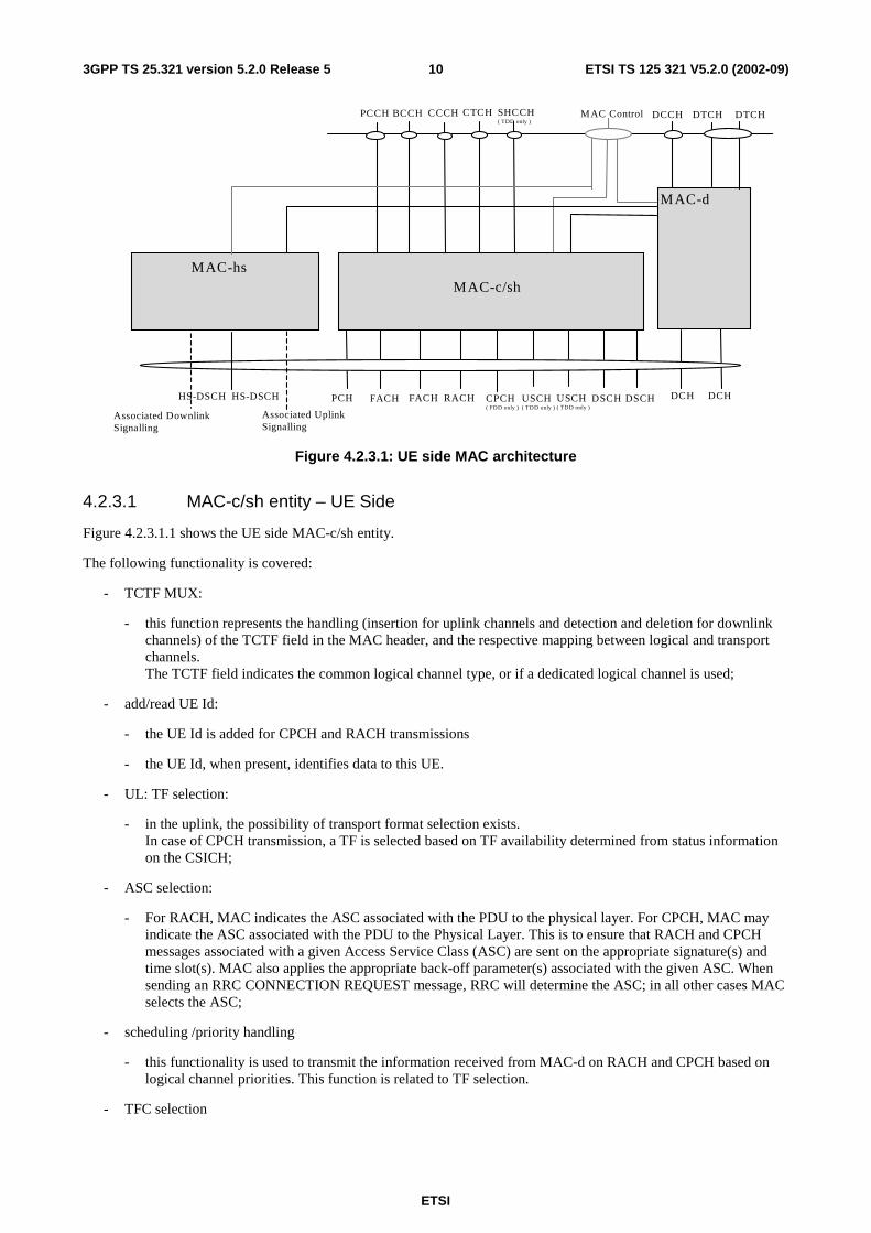
Figure 4.2.3.1.1 shows the UE side MAC-c/sh entity.
The following functionality is covered:
- TCTF MUX:
- this function represents the handling (insertion for uplink channels and detection and deletion for downlink channels) of the TCTF field in the MAC header, and the respective mapping between logical and transport channels. The TCTF field indicates the common logical channel type, or if a dedicated logical channel is used;
- add/read UE Id:
- the UE Id is added for CPCH and RACH transmissions
- the UE Id, when present, identifies data to this UE.
- UL: TF selection:
- in the uplink, the possibility of transport format selection exists. In case of CPCH transmission, a TF is selected based on TF availability determined from status information on the CSICH;
- ASC selection:
- For RACH, MAC indicates the ASC associated with the PDU to the physical layer. For CPCH, MAC may indicate the ASC associated with the PDU to the Physical Layer. This is to ensure that RACH and CPCH messages associated with a given Access Service Class (ASC) are sent on the appropriate signature(s) and time slot(s). MAC also applies the appropriate back-off parameter(s) associated with the given ASC. When sending an RRC CONNECTION REQUEST message, RRC will determine the ASC; in all other cases MAC selects the ASC;
- scheduling /priority handling
- this functionality is used to transmit the information received from MAC-d on RACH and CPCH based on logical channel priorities. This function is related to TF selection.
- TFC selection
ETSI
ETSI TS 125 321 V5.2.0 (2002-09) 113GPP TS 25.321 version 5.2.0 Release 5
- transport format and transport format combination selection according to the transport format combination set (or transport format combination subset) configured by RRC is performed,
The RLC provides RLC-PDUs to the MAC, which fit into the available transport blocks on the transport channels.
There is one MAC-c/sh entity in each UE.
MAC-c/sh
MAC – Control
to MAC –d
FACH CPCH ( FDD only ) FACH
CTCH CCCH BCCH SHCCH (TDD only) PCCH
PCH
UL: TF selection
USCH TDD only
DSCH RACH
Scheduling/Priority Handling (1)
add/read UE Id
DSCH USCH TDD only
TFC selection
TCTF MUX
ASC selection
ASC selection (2)
Note 1: Scheduling /Priority handling is applicable for CPCH. Note 2: In case of CPCH, ASC selection may be applicable for AP preamble.
Figure 4.2.3.1.1: UE side MAC architecture / MAC-c/sh details
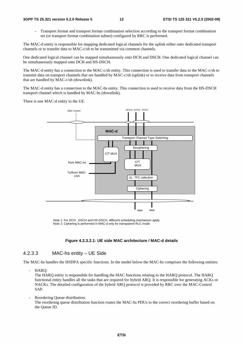
4.2.3.2 MAC-d entity – UE Side
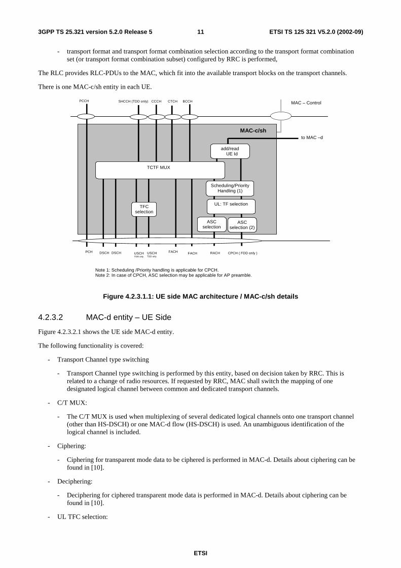
Figure 4.2.3.2.1 shows the UE side MAC-d entity.
The following functionality is covered:
- Transport Channel type switching
- Transport Channel type switching is performed by this entity, based on decision taken by RRC. This is related to a change of radio resources. If requested by RRC, MAC shall switch the mapping of one designated logical channel between common and dedicated transport channels.
- C/T MUX:
- The C/T MUX is used when multiplexing of several dedicated logical channels onto one transport channel (other than HS-DSCH) or one MAC-d flow (HS-DSCH) is used. An unambiguous identification of the logical channel is included.
- Ciphering:
- Ciphering for transparent mode data to be ciphered is performed in MAC-d. Details about ciphering can be found in [10].
- Deciphering:
- Deciphering for ciphered transparent mode data is performed in MAC-d. Details about ciphering can be found in [10].
- UL TFC selection:
ETSI
ETSI TS 125 321 V5.2.0 (2002-09) 123GPP TS 25.321 version 5.2.0 Release 5
- Transport format and transport format combination selection according to the transport format combination set (or transport format combination subset) configured by RRC is performed.
The MAC-d entity is responsible for mapping dedicated logical channels for the uplink either onto dedicated transport channels or to transfer data to MAC-c/sh to be transmitted via common channels.
One dedicated logical channel can be mapped simultaneously onto DCH and DSCH. One dedicated logical channel can be simultaneously mapped onto DCH and HS-DSCH.
The MAC-d entity has a connection to the MAC-c/sh entity. This connection is used to transfer data to the MAC-c/sh to transmit data on transport channels that are handled by MAC-c/sh (uplink) or to receive data from transport channels that are handled by MAC-c/sh (downlink).
The MAC-d entity has a connection to the MAC-hs entity. This connection is used to receive data from the HS-DSCH transport channel which is handled by MAC-hs (downlink).
There is one MAC-d entity in the UE.
DCCH DTCH DTCH
DCH DCH
MAC-d
from MAC-hs
Ciphering
MAC Control
UL: TFC selection
C/T MUX
C/T MUX
Deciphering
Transport Channel Type Switching
Note 1: For DCH , DSCH and HS-DSCH, different scheduling mechanism apply Note 2: Ciphering is performed in MAC-d only for transparent RLC mode
To/from MAC-c/sh
Figure 4.2.3.2.1: UE side MAC architecture / MAC-d details
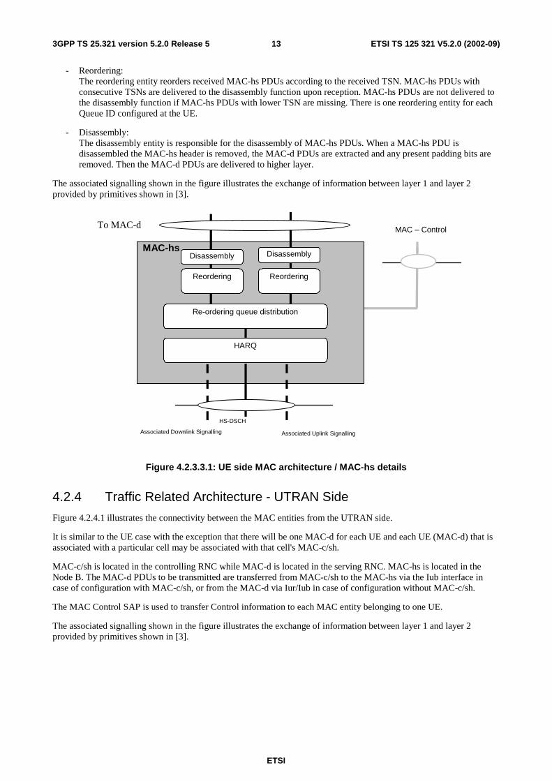
4.2.3.3 MAC-hs entity – UE Side
The MAC-hs handles the HSDPA specific functions. In the model below the MAC-hs comprises the following entities:
- HARQ: The HARQ entity is responsible for handling the MAC functions relating to the HARQ protocol. The HARQ functional entity handles all the tasks that are required for hybrid ARQ. It is responsible for generating ACKs or NACKs. The detailed configuration of the hybrid ARQ protocol is provided by RRC over the MAC-Control SAP.
- Reordering Queue distribution: The reordering queue distribution function routes the MAC-hs PDUs to the correct reordering buffer based on the Queue ID.
ETSI
ETSI TS 125 321 V5.2.0 (2002-09) 133GPP TS 25.321 version 5.2.0 Release 5
- Reordering: The reordering entity reorders received MAC-hs PDUs according to the received TSN. MAC-hs PDUs with consecutive TSNs are delivered to the disassembly function upon reception. MAC-hs PDUs are not delivered to the disassembly function if MAC-hs PDUs with lower TSN are missing. There is one reordering entity for each Queue ID configured at the UE.
- Disassembly: The disassembly entity is responsible for the disassembly of MAC-hs PDUs. When a MAC-hs PDU is disassembled the MAC-hs header is removed, the MAC-d PDUs are extracted and any present padding bits are removed. Then the MAC-d PDUs are delivered to higher layer.
The associated signalling shown in the figure illustrates the exchange of information between layer 1 and layer 2 provided by primitives shown in [3].
MAC-hs
MAC – Control
Associated Uplink Signalling
To MAC-d
Associated Downlink Signalling
HS-DSCH
HARQ
Reordering Reordering
Re-ordering queue distribution
Disassembly Disassembly
Figure 4.2.3.3.1: UE side MAC architecture / MAC-hs details
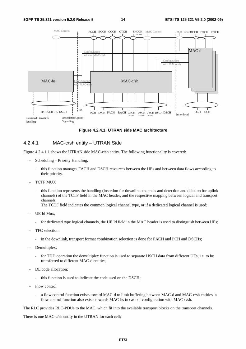
4.2.4 Traffic Related Architecture - UTRAN Side
Figure 4.2.4.1 illustrates the connectivity between the MAC entities from the UTRAN side.
It is similar to the UE case with the exception that there will be one MAC-d for each UE and each UE (MAC-d) that is associated with a particular cell may be associated with that cell's MAC-c/sh.
MAC-c/sh is located in the controlling RNC while MAC-d is located in the serving RNC. MAC-hs is located in the Node B. The MAC-d PDUs to be transmitted are transferred from MAC-c/sh to the MAC-hs via the Iub interface in case of configuration with MAC-c/sh, or from the MAC-d via Iur/Iub in case of configuration without MAC-c/sh.
The MAC Control SAP is used to transfer Control information to each MAC entity belonging to one UE.
The associated signalling shown in the figure illustrates the exchange of information between layer 1 and layer 2 provided by primitives shown in [3].
ETSI
ETSI TS 125 321 V5.2.0 (2002-09) 143GPP TS 25.321 version 5.2.0 Release 5
HS-DSCH HS-DSCH
Associated UplinkSignalling
ssociated Downlinkignalling
FACH RACH
DCCH DTCHDTCH
DSCH
MAC Control
Iur or local
MAC Control
DCH DCH
MAC-d
USCHTDD only
MAC-c/sh
CPCHFDD only
CCCH CTCHBCCH SHCCH TDD only
PCCH
FACHPCH USCHTDD only
DSCHIub
MAC Control
MAC-hs
Configurationwithout MAC-c/sh
Configurationwith MAC-c/sh
Configurationwith MAC-c/sh
Figure 4.2.4.1: UTRAN side MAC architecture
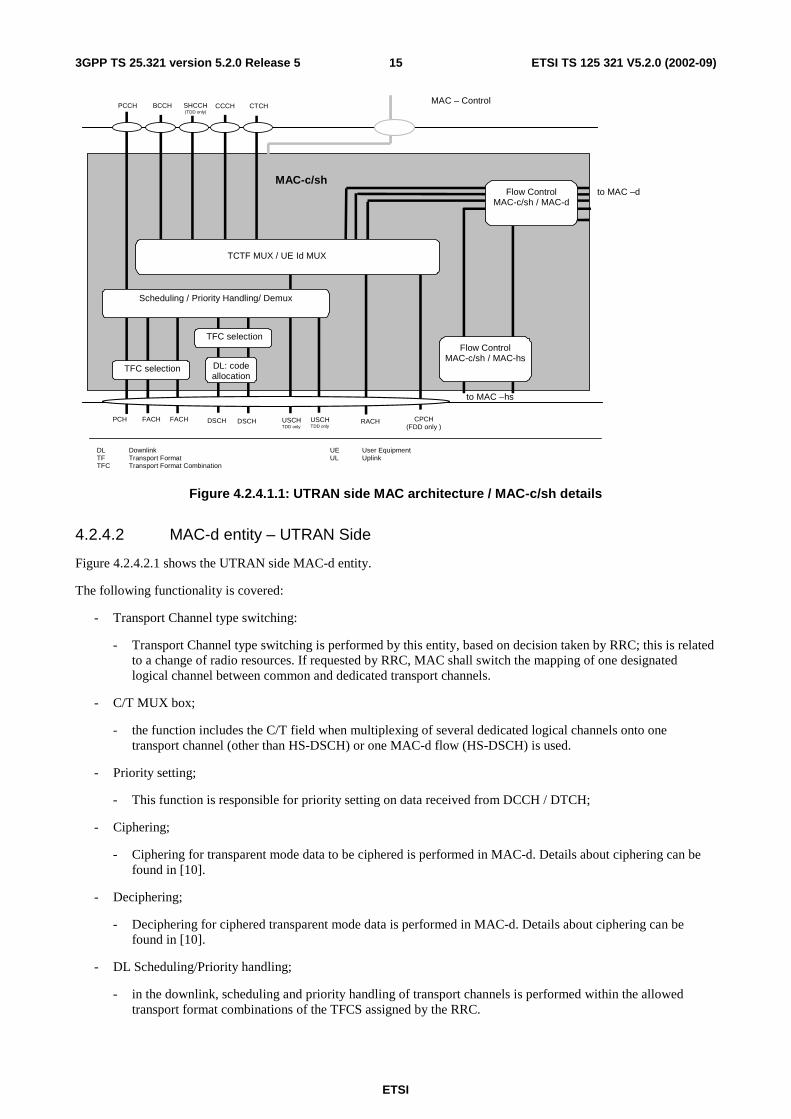
4.2.4.1 MAC-c/sh entity – UTRAN Side
Figure 4.2.4.1.1 shows the UTRAN side MAC-c/sh entity. The following functionality is covered:
- Scheduling – Priority Handling;
- this function manages FACH and DSCH resources between the UEs and between data flows according to their priority.
- TCTF MUX
- this function represents the handling (insertion for downlink channels and detection and deletion for uplink channels) of the TCTF field in the MAC header, and the respective mapping between logical and transport channels. The TCTF field indicates the common logical channel type, or if a dedicated logical channel is used;
- UE Id Mux;
- for dedicated type logical channels, the UE Id field in the MAC header is used to distinguish between UEs;
- TFC selection:
- in the downlink, transport format combination selection is done for FACH and PCH and DSCHs;
- Demultiplex;
- for TDD operation the demultiplex function is used to separate USCH data from different UEs, i.e. to be transferred to different MAC-d entities;
- DL code allocation;
- this function is used to indicate the code used on the DSCH;
- Flow control;
- a flow control function exists toward MAC-d to limit buffering between MAC-d and MAC-c/sh entities. a flow control function also exists towards MAC-hs in case of configuration with MAC-c/sh.
The RLC provides RLC-PDUs to the MAC, which fit into the available transport blocks on the transport channels.
There is one MAC-c/sh entity in the UTRAN for each cell;
ETSI
ETSI TS 125 321 V5.2.0 (2002-09) 153GPP TS 25.321 version 5.2.0 Release 5
DL Downlink TF Transport Format TFC Transport Format Combination
UE User Equipment UL Uplink
CTCH
FACH
MAC-c/sh to MAC –d
RACH
MAC – Control
CPCH (FDD only )
CCCH
FACH
BCCH SHCCH (TDD only)
PCCH
PCH
TFC selection
DSCH USCH TDD only
TCTF MUX / UE Id MUX
USCH TDD only
DSCH
DL: code allocation
Scheduling / Priority Handling/ Demux
TFC selection
to MAC –hs
Flow Control MAC-c/sh / MAC-d
Flow Control MAC-c/sh / MAC-hs
Figure 4.2.4.1.1: UTRAN side MAC architecture / MAC-c/sh details
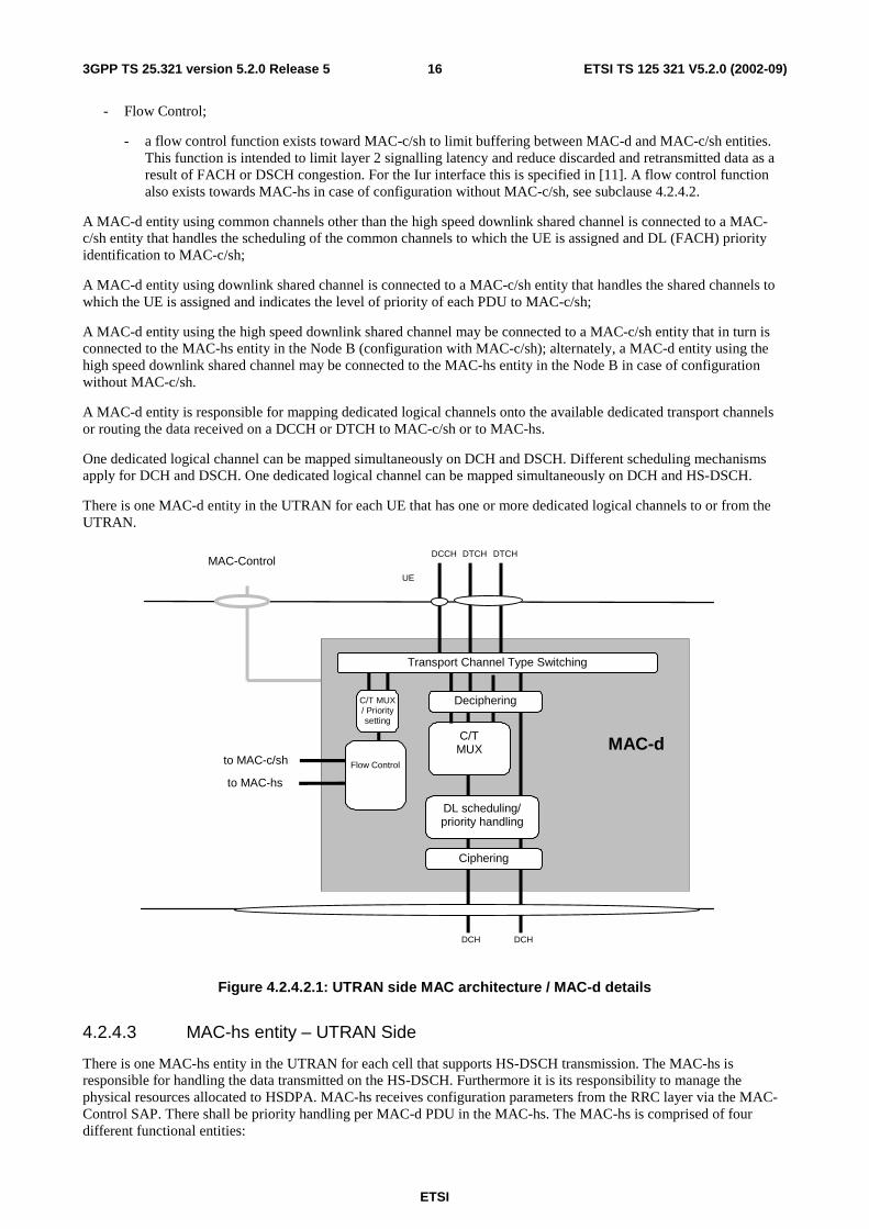
4.2.4.2 MAC-d entity – UTRAN Side
Figure 4.2.4.2.1 shows the UTRAN side MAC-d entity.
The following functionality is covered:
- Transport Channel type switching:
- Transport Channel type switching is performed by this entity, based on decision taken by RRC; this is related to a change of radio resources. If requested by RRC, MAC shall switch the mapping of one designated logical channel between common and dedicated transport channels.
- C/T MUX box;
- the function includes the C/T field when multiplexing of several dedicated logical channels onto one transport channel (other than HS-DSCH) or one MAC-d flow (HS-DSCH) is used.
- Priority setting;
- This function is responsible for priority setting on data received from DCCH / DTCH;
- Ciphering;
- Ciphering for transparent mode data to be ciphered is performed in MAC-d. Details about ciphering can be found in [10].
- Deciphering;
- Deciphering for ciphered transparent mode data is performed in MAC-d. Details about ciphering can be found in [10].
- DL Scheduling/Priority handling;
- in the downlink, scheduling and priority handling of transport channels is performed within the allowed transport format combinations of the TFCS assigned by the RRC.
ETSI
ETSI TS 125 321 V5.2.0 (2002-09) 163GPP TS 25.321 version 5.2.0 Release 5
- Flow Control;
- a flow control function exists toward MAC-c/sh to limit buffering between MAC-d and MAC-c/sh entities. This function is intended to limit layer 2 signalling latency and reduce discarded and retransmitted data as a result of FACH or DSCH congestion. For the Iur interface this is specified in [11]. A flow control function also exists towards MAC-hs in case of configuration without MAC-c/sh, see subclause 4.2.4.2.
A MAC-d entity using common channels other than the high speed downlink shared channel is connected to a MAC-c/sh entity that handles the scheduling of the common channels to which the UE is assigned and DL (FACH) priority identification to MAC-c/sh;
A MAC-d entity using downlink shared channel is connected to a MAC-c/sh entity that handles the shared channels to which the UE is assigned and indicates the level of priority of each PDU to MAC-c/sh;
A MAC-d entity using the high speed downlink shared channel may be connected to a MAC-c/sh entity that in turn is connected to the MAC-hs entity in the Node B (configuration with MAC-c/sh); alternately, a MAC-d entity using the high speed downlink shared channel may be connected to the MAC-hs entity in the Node B in case of configuration without MAC-c/sh.
A MAC-d entity is responsible for mapping dedicated logical channels onto the available dedicated transport channels or routing the data received on a DCCH or DTCH to MAC-c/sh or to MAC-hs.
One dedicated logical channel can be mapped simultaneously on DCH and DSCH. Different scheduling mechanisms apply for DCH and DSCH. One dedicated logical channel can be mapped simultaneously on DCH and HS-DSCH.
There is one MAC-d entity in the UTRAN for each UE that has one or more dedicated logical channels to or from the UTRAN.
DCCH
UE
DTCH DTCH
DCH DCH
MAC-dto MAC-c/sh
MAC-Control
C/TMUX
DL scheduling/priority handling
Ciphering
Transport Channel Type Switching
C/T MUX/ Prioritysetting
Deciphering
to MAC-hs
Flow Control
Figure 4.2.4.2.1: UTRAN side MAC architecture / MAC-d details
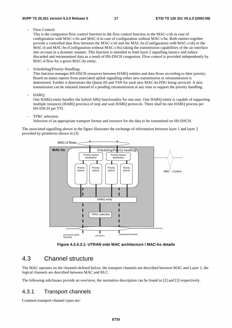
4.2.4.3 MAC-hs entity – UTRAN Side
There is one MAC-hs entity in the UTRAN for each cell that supports HS-DSCH transmission. The MAC-hs is responsible for handling the data transmitted on the HS-DSCH. Furthermore it is its responsibility to manage the physical resources allocated to HSDPA. MAC-hs receives configuration parameters from the RRC layer via the MAC-Control SAP. There shall be priority handling per MAC-d PDU in the MAC-hs. The MAC-hs is comprised of four different functional entities:
ETSI
ETSI TS 125 321 V5.2.0 (2002-09) 173GPP TS 25.321 version 5.2.0 Release 5
- Flow Control: This is the companion flow control function to the flow control function in the MAC-c/sh in case of configuration with MAC-c/hs and MAC-d in case of configuration without MAC-c/hs. Both entities together provide a controlled data flow between the MAC-c/sh and the MAC-hs (Configuration with MAC-c/sh) or the MAC-d and MAC-hs (Configuration without MAC-c/hs) taking the transmission capabilities of the air interface into account in a dynamic manner. This function is intended to limit layer 2 signalling latency and reduce discarded and retransmitted data as a result of HS-DSCH congestion. Flow control is provided independently by MAC-d flow for a given MAC-hs entity.
- Scheduling/Priority Handling: This function manages HS-DSCH resources between HARQ entities and data flows according to their priority. Based on status reports from associated uplink signalling either new transmission or retransmission is determined. Further it determines the Queue ID and TSN for each new MAC-hs PDU being serviced. A new transmission can be initiated instead of a pending retransmission at any time to support the priority handling.
- HARQ: One HARQ entity handles the hybrid ARQ functionality for one user. One HARQ entity is capable of supporting multiple instances (HARQ process) of stop and wait HARQ protocols. There shall be one HARQ process per HS-DSCH per TTI.
- TFRC selection: Selection of an appropriate transport format and resource for the data to be transmitted on HS-DSCH.
The associated signalling shown in the figure illustrates the exchange of information between layer 1 and layer 2 provided by primitives shown in [3].
MAC-hs
MAC – Control
HS-DSCH
TFRC selection
Priority Queuedistribution
Associated DownlinkAssociated UplinkSignalling
MAC-d flows
HARQ entity
Priority Queuedistribution
PriorityQueue
PriorityQueue
PriorityQueue
PriorityQueue
Scheduling/Priority handling
Figure 4.2.4.3.1: UTRAN side MAC architecture / MAC-hs details
4.3 Channel structure The MAC operates on the channels defined below; the transport channels are described between MAC and Layer 1, the logical channels are described between MAC and RLC.
The following subclauses provide an overview, the normative description can be found in [2] and [3] respectively.
4.3.1 Transport channels
Common transport channel types are:
ETSI
ETSI TS 125 321 V5.2.0 (2002-09) 183GPP TS 25.321 version 5.2.0 Release 5
- Random Access Channel(s) (RACH);
- Forward Access Channel(s) (FACH);
- Downlink Shared Channel(s) (DSCH);
- High Speed Downlink Shared Channel(s) (HS-DSCH);
- Common Packet Channel(s) (CPCH) for UL FDD operation only;
- Uplink Shared Channel(s) (USCH), for TDD operation only;
- Broadcast Channel (BCH);
- Paging Channel (PCH).
Dedicated transport channel types are:
- Dedicated Channel (DCH).
4.3.2 Logical Channels
The MAC layer provides data transfer services on logical channels. A set of logical channel types is defined for different kinds of data transfer services as offered by MAC.
Each logical channel type is defined by what type of information is transferred.
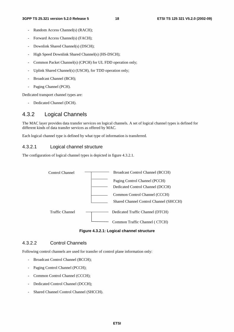
4.3.2.1 Logical channel structure
The configuration of logical channel types is depicted in figure 4.3.2.1.
Broadcast Control Channel (BCCH)
Paging Control Channel (PCCH)
Dedicated Control Channel (DCCH)
Common Control Channel (CCCH)
Control Channel
Dedicated Traffic Channel (DTCH) Traffic Channel
Common Traffic Channel ( CTCH)
Shared Channel Control Channel (SHCCH)
Figure 4.3.2.1: Logical channel structure
4.3.2.2 Control Channels
Following control channels are used for transfer of control plane information only:
- Broadcast Control Channel (BCCH);
- Paging Control Channel (PCCH);
- Common Control Channel (CCCH);
- Dedicated Control Channel (DCCH);
- Shared Channel Control Channel (SHCCH).
ETSI
ETSI TS 125 321 V5.2.0 (2002-09) 193GPP TS 25.321 version 5.2.0 Release 5
4.3.2.3 Traffic Channels
Following traffic channels are used for the transfer of user plane information only:
- Dedicated Traffic Channel (DTCH);
- Common Traffic Channel (CTCH).
5 Services provided to upper layers This clause describes the different services provided by the MAC to higher layers. For a detailed description of the following functions see [2].
5.1 Description of Services provided to upper layers - Data transfer: This service provides unacknowledged transfer of MAC SDUs between peer MAC entities
without data segmentation.
- Reallocation of radio resources and MAC parameters: This service performs on request of RRC execution of radio resource reallocation and change of MAC parameters.
- Reporting of measurements: Local measurements are reported to RRC.
6 Functions
6.1 Description of the MAC functions The functions of MAC include:
- mapping between logical channels and transport channels;
- selection of appropriate Transport Format for each Transport Channel depending on instantaneous source rate;
- priority handling between data flows of one UE;
- priority handling between UEs by means of dynamic scheduling;
- identification of UEs on common transport channels;
- multiplexing/demultiplexing of upper layer PDUs into/from transport blocks delivered to/from the physical layer on common transport channels;
- multiplexing/demultiplexing of upper layer PDUs into/from transport block sets delivered to/from the physical layer on dedicated transport channels;
- traffic volume measurement;
- Transport Channel type switching;
- ciphering for transparent mode RLC;
- Access Service Class selection for RACH and CPCH transmission;
- control of HS-DSCH transmission and reception including support of HARQ.
ETSI
ETSI TS 125 321 V5.2.0 (2002-09) 203GPP TS 25.321 version 5.2.0 Release 5
6.2 Relation between MAC Functions and Transport Channels
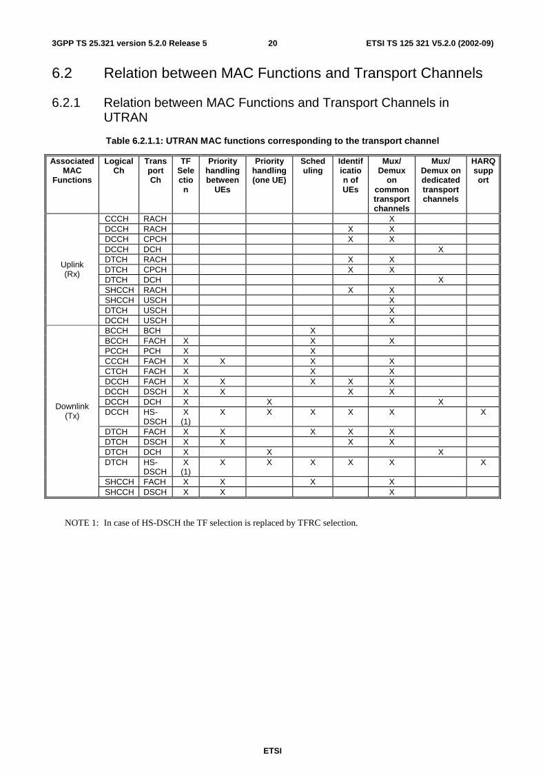
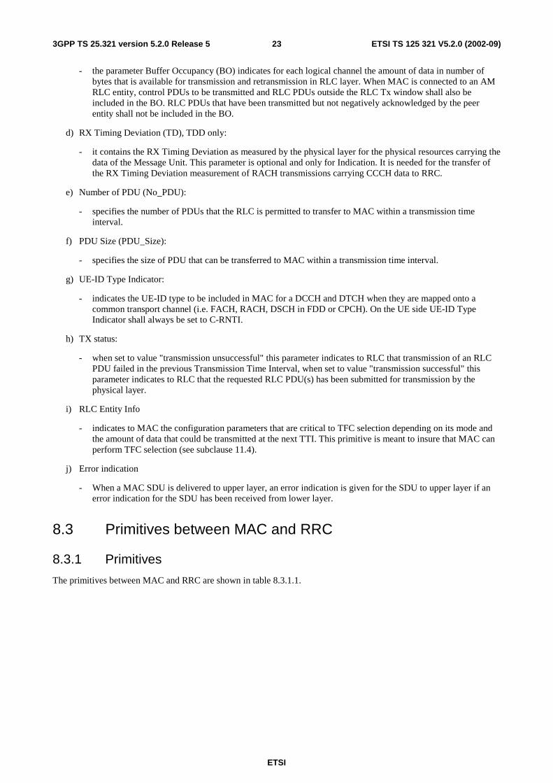
6.2.1 Relation between MAC Functions and Transport Channels in UTRAN
Table 6.2.1.1: UTRAN MAC functions corresponding to the transport channel
Associated MAC
Functions
Logical Ch
Trans port Ch
TF Selectio
n
Priority handling between
UEs
Priority handling (one UE)
Sched uling
Identification of UEs
Mux/ Demux
on common transport channels
Mux/ Demux on dedicated transport channels
HARQ support
CCCH RACH X DCCH RACH X X DCCH CPCH X X DCCH DCH X DTCH RACH X X DTCH CPCH X X DTCH DCH X SHCCH RACH X X SHCCH USCH X DTCH USCH X
Uplink (Rx)
DCCH USCH X BCCH BCH X BCCH FACH X X X PCCH PCH X X CCCH FACH X X X X CTCH FACH X X X DCCH FACH X X X X X DCCH DSCH X X X X DCCH DCH X X X DCCH HS-
DSCH X
(1) X X X X X X
DTCH FACH X X X X X DTCH DSCH X X X X DTCH DCH X X X DTCH HS-
DSCH X
(1) X X X X X X
SHCCH FACH X X X X
Downlink (Tx)
SHCCH DSCH X X X
NOTE 1: In case of HS-DSCH the TF selection is replaced by TFRC selection.
ETSI
ETSI TS 125 321 V5.2.0 (2002-09) 213GPP TS 25.321 version 5.2.0 Release 5
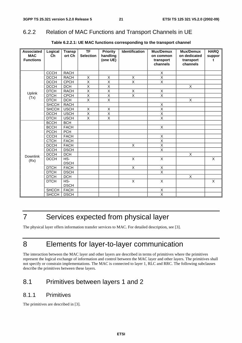
6.2.2 Relation of MAC Functions and Transport Channels in UE
Table 6.2.2.1: UE MAC functions corresponding to the transport channel
Associated MAC
Functions
Logical Ch
Transport Ch
TF Selection
Priority handling (one UE)
Identification Mux/Demux on common
transport channels
Mux/Demux on dedicated
transport channels
HARQ suppor
t
CCCH RACH X DCCH RACH X X X X DCCH CPCH X X X X DCCH DCH X X X DTCH RACH X X X X DTCH CPCH X X X X DTCH DCH X X X SHCCH RACH X SHCCH USCH X X X DCCH USCH X X X
Uplink (Tx)
DTCH USCH X X X BCCH BCH BCCH FACH X PCCH PCH CCCH FACH X CTCH FACH X DCCH FACH X X DCCH DSCH X DCCH DCH X DCCH HS-
DSCH X X X
DTCH FACH X X DTCH DSCH X DTCH DCH X DTCH HS-
DSCH X X X
SHCCH FACH X
Downlink (Rx)
SHCCH DSCH X
7 Services expected from physical layer The physical layer offers information transfer services to MAC. For detailed description, see [3].
8 Elements for layer-to-layer communication The interaction between the MAC layer and other layers are described in terms of primitives where the primitives represent the logical exchange of information and control between the MAC layer and other layers. The primitives shall not specify or constrain implementations. The MAC is connected to layer 1, RLC and RRC. The following subclauses describe the primitives between these layers.
8.1 Primitives between layers 1 and 2
8.1.1 Primitives
The primitives are described in [3].
ETSI
ETSI TS 125 321 V5.2.0 (2002-09) 223GPP TS 25.321 version 5.2.0 Release 5
8.1.2 Parameters
a) Transport Format Resource Indicator (TFRI) for HS-DSCH:
- For HS-DSCH the Transport Block size is derived from the TFRI value signalled on the HS-SCCH. The mapping between TFRI value and Transport Block size is specified in subclause 9.2.3.
8.2 Primitives between MAC and RLC
8.2.1 Primitives
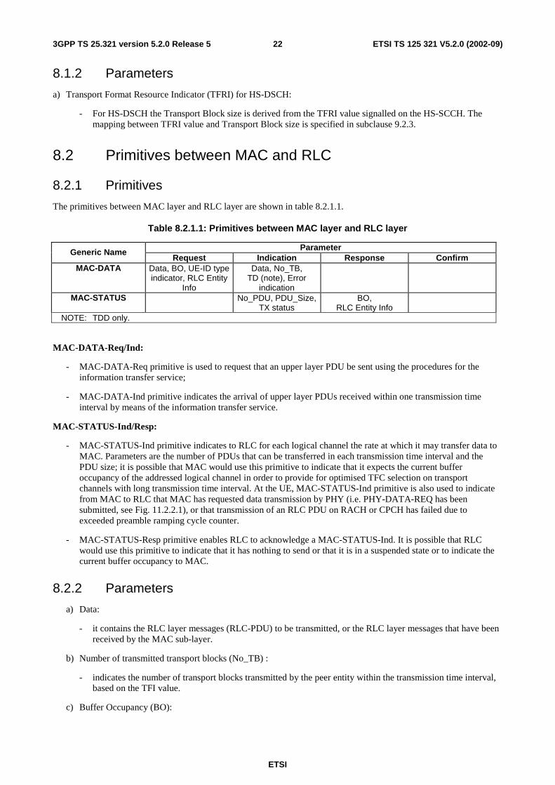
The primitives between MAC layer and RLC layer are shown in table 8.2.1.1.
Table 8.2.1.1: Primitives between MAC layer and RLC layer
Parameter Generic Name Request Indication Response Confirm
MAC-DATA Data, BO, UE-ID type indicator, RLC Entity
Info
Data, No_TB, TD (note), Error
indication
MAC-STATUS No_PDU, PDU_Size, TX status
BO, RLC Entity Info
NOTE: TDD only.
MAC-DATA-Req/Ind:
- MAC-DATA-Req primitive is used to request that an upper layer PDU be sent using the procedures for the information transfer service;
- MAC-DATA-Ind primitive indicates the arrival of upper layer PDUs received within one transmission time interval by means of the information transfer service.
MAC-STATUS-Ind/Resp:
- MAC-STATUS-Ind primitive indicates to RLC for each logical channel the rate at which it may transfer data to MAC. Parameters are the number of PDUs that can be transferred in each transmission time interval and the PDU size; it is possible that MAC would use this primitive to indicate that it expects the current buffer occupancy of the addressed logical channel in order to provide for optimised TFC selection on transport channels with long transmission time interval. At the UE, MAC-STATUS-Ind primitive is also used to indicate from MAC to RLC that MAC has requested data transmission by PHY (i.e. PHY-DATA-REQ has been submitted, see Fig. 11.2.2.1), or that transmission of an RLC PDU on RACH or CPCH has failed due to exceeded preamble ramping cycle counter.
- MAC-STATUS-Resp primitive enables RLC to acknowledge a MAC-STATUS-Ind. It is possible that RLC would use this primitive to indicate that it has nothing to send or that it is in a suspended state or to indicate the current buffer occupancy to MAC.
8.2.2 Parameters
a) Data:
- it contains the RLC layer messages (RLC-PDU) to be transmitted, or the RLC layer messages that have been received by the MAC sub-layer.
b) Number of transmitted transport blocks (No_TB) :
- indicates the number of transport blocks transmitted by the peer entity within the transmission time interval, based on the TFI value.
c) Buffer Occupancy (BO):
ETSI
ETSI TS 125 321 V5.2.0 (2002-09) 233GPP TS 25.321 version 5.2.0 Release 5
- the parameter Buffer Occupancy (BO) indicates for each logical channel the amount of data in number of bytes that is available for transmission and retransmission in RLC layer. When MAC is connected to an AM RLC entity, control PDUs to be transmitted and RLC PDUs outside the RLC Tx window shall also be included in the BO. RLC PDUs that have been transmitted but not negatively acknowledged by the peer entity shall not be included in the BO.
d) RX Timing Deviation (TD), TDD only:
- it contains the RX Timing Deviation as measured by the physical layer for the physical resources carrying the data of the Message Unit. This parameter is optional and only for Indication. It is needed for the transfer of the RX Timing Deviation measurement of RACH transmissions carrying CCCH data to RRC.
e) Number of PDU (No_PDU):
- specifies the number of PDUs that the RLC is permitted to transfer to MAC within a transmission time interval.
f) PDU Size (PDU_Size):
- specifies the size of PDU that can be transferred to MAC within a transmission time interval.
g) UE-ID Type Indicator:
- indicates the UE-ID type to be included in MAC for a DCCH and DTCH when they are mapped onto a common transport channel (i.e. FACH, RACH, DSCH in FDD or CPCH). On the UE side UE-ID Type Indicator shall always be set to C-RNTI.
h) TX status:
- when set to value "transmission unsuccessful" this parameter indicates to RLC that transmission of an RLC PDU failed in the previous Transmission Time Interval, when set to value "transmission successful" this parameter indicates to RLC that the requested RLC PDU(s) has been submitted for transmission by the physical layer.
i) RLC Entity Info
- indicates to MAC the configuration parameters that are critical to TFC selection depending on its mode and the amount of data that could be transmitted at the next TTI. This primitive is meant to insure that MAC can perform TFC selection (see subclause 11.4).
j) Error indication
- When a MAC SDU is delivered to upper layer, an error indication is given for the SDU to upper layer if an error indication for the SDU has been received from lower layer.
8.3 Primitives between MAC and RRC
8.3.1 Primitives
The primitives between MAC and RRC are shown in table 8.3.1.1.
ETSI
ETSI TS 125 321 V5.2.0 (2002-09) 243GPP TS 25.321 version 5.2.0 Release 5
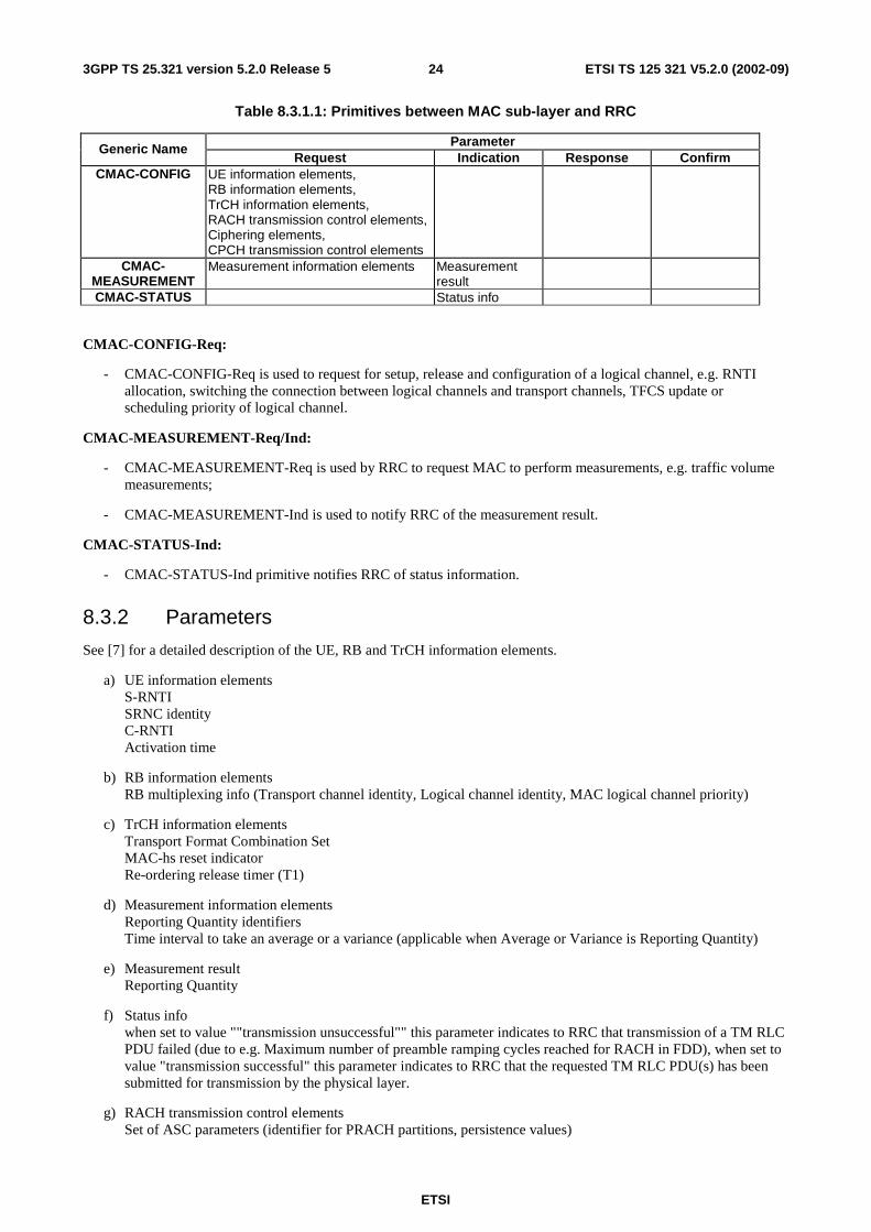
Table 8.3.1.1: Primitives between MAC sub-layer and RRC
Parameter Generic Name Request Indication Response Confirm
CMAC-CONFIG UE information elements, RB information elements, TrCH information elements, RACH transmission control elements, Ciphering elements, CPCH transmission control elements
CMAC-MEASUREMENT
Measurement information elements Measurement result
CMAC-STATUS Status info
CMAC-CONFIG-Req:
- CMAC-CONFIG-Req is used to request for setup, release and configuration of a logical channel, e.g. RNTI allocation, switching the connection between logical channels and transport channels, TFCS update or scheduling priority of logical channel.
CMAC-MEASUREMENT-Req/Ind:
- CMAC-MEASUREMENT-Req is used by RRC to request MAC to perform measurements, e.g. traffic volume measurements;
- CMAC-MEASUREMENT-Ind is used to notify RRC of the measurement result.
CMAC-STATUS-Ind:
- CMAC-STATUS-Ind primitive notifies RRC of status information.
8.3.2 Parameters
See [7] for a detailed description of the UE, RB and TrCH information elements.
a) UE information elements S-RNTI SRNC identity C-RNTI Activation time
b) RB information elements RB multiplexing info (Transport channel identity, Logical channel identity, MAC logical channel priority)
c) TrCH information elements Transport Format Combination Set MAC-hs reset indicator Re-ordering release timer (T1)
d) Measurement information elements Reporting Quantity identifiers Time interval to take an average or a variance (applicable when Average or Variance is Reporting Quantity)
e) Measurement result Reporting Quantity
f) Status info when set to value ""transmission unsuccessful"" this parameter indicates to RRC that transmission of a TM RLC PDU failed (due to e.g. Maximum number of preamble ramping cycles reached for RACH in FDD), when set to value "transmission successful" this parameter indicates to RRC that the requested TM RLC PDU(s) has been submitted for transmission by the physical layer.
g) RACH transmission control elements Set of ASC parameters (identifier for PRACH partitions, persistence values)
ETSI
ETSI TS 125 321 V5.2.0 (2002-09) 253GPP TS 25.321 version 5.2.0 Release 5
Maximum number of preamble ramping cycles (FDD) or synchronisation attempts (1.28 Mcps TDD) Mmax
Minimum and maximum number of time units between two preamble ramping cycles, NBO1min and NBO1max (FDD only) ASC for RRC CONNECTION REQUEST message
h) Ciphering elements Ciphering mode Ciphering key Ciphering sequence number
i) CPCH transmission control elements CPCH persistency value, P for each Transport Format Maximum number of preamble ramping cycles N_access_fails NF_max (Maximum number of frames for CPCH transmission for each Transport Format) N_EOT (Number of EOT for release of CPCH transmission) Backoff control timer parameters Transport Format Set Initial Priority Delays Channel Assignment Active indication
9 Elements for peer-to-peer communication
9.1 Protocol data units
9.1.1 General
A MAC PDU is a bit string, with a length not necessarily a multiple of 8 bits. In the drawings in clause 9.1, bit strings are represented by tables in which the first bit is the leftmost one on the first line of the table, the last bit is the rightmost on the last line of the table, and more generally the bit string is to be read from left to right and then in the reading order of the lines.
Depending on the provided service, MAC SDUs are bit strings with any non-null length, or bit strings with an integer number of octets in length. An SDU is included into a MAC PDU from first bit onward.
In the UE for the uplink, all MAC PDUs delivered to the physical layer within one TTI are defined as Transport Block Set (TBS). It consists of one or several Transport Blocks, each containing one MAC PDU. The Transport Blocks, shall be transmitted in the order as delivered from RLC. When multiplexing of RLC PDUs from different logical channels is performed on MAC, the order of all Transport Blocks originating from the same logical channel shall be the same as the order of the sequence delivered from RLC. The order of the different logical channels in a TBS is set by the MAC protocol.
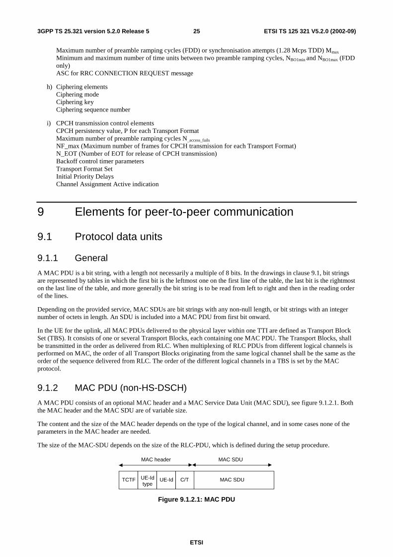
9.1.2 MAC PDU (non-HS-DSCH)
A MAC PDU consists of an optional MAC header and a MAC Service Data Unit (MAC SDU), see figure 9.1.2.1. Both the MAC header and the MAC SDU are of variable size.
The content and the size of the MAC header depends on the type of the logical channel, and in some cases none of the parameters in the MAC header are needed.
The size of the MAC-SDU depends on the size of the RLC-PDU, which is defined during the setup procedure.
MAC SDUC/TUE-Id
MAC header MAC SDU
TCTF UE-Idtype
Figure 9.1.2.1: MAC PDU
ETSI
ETSI TS 125 321 V5.2.0 (2002-09) 263GPP TS 25.321 version 5.2.0 Release 5
9.1.3 MAC-d PDU (HS-DSCH)
For HS-DSCH the MAC-d PDU format equals the MAC PDU format for the non HS-DSCH case.
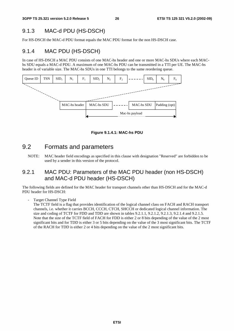
9.1.4 MAC PDU (HS-DSCH)
In case of HS-DSCH a MAC PDU consists of one MAC-hs header and one or more MAC-hs SDUs where each MAC-hs SDU equals a MAC-d PDU. A maximum of one MAC-hs PDU can be transmitted in a TTI per UE. The MAC-hs header is of variable size. The MAC-hs SDUs in one TTI belongs to the same reordering queue.
Queue ID TSN SID1 N1 F1 SIDk Nk Fk SID2 N2 F2
MAC-hs header MAC-hs SDU Padding (opt) MAC-hs SDU
Mac-hs payload
Figure 9.1.4.1: MAC-hs PDU
9.2 Formats and parameters NOTE: MAC header field encodings as specified in this clause with designation "Reserved" are forbidden to be
used by a sender in this version of the protocol.
9.2.1 MAC PDU: Parameters of the MAC PDU header (non HS-DSCH) and MAC-d PDU header (HS-DSCH)
The following fields are defined for the MAC header for transport channels other than HS-DSCH and for the MAC-d PDU header for HS-DSCH:
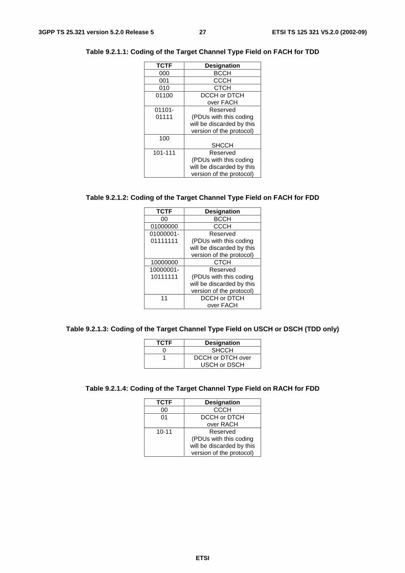
- Target Channel Type Field The TCTF field is a flag that provides identification of the logical channel class on FACH and RACH transport channels, i.e. whether it carries BCCH, CCCH, CTCH, SHCCH or dedicated logical channel information. The size and coding of TCTF for FDD and TDD are shown in tables 9.2.1.1, 9.2.1.2, 9.2.1.3, 9.2.1.4 and 9.2.1.5. Note that the size of the TCTF field of FACH for FDD is either 2 or 8 bits depending of the value of the 2 most significant bits and for TDD is either 3 or 5 bits depending on the value of the 3 most significant bits. The TCTF of the RACH for TDD is either 2 or 4 bits depending on the value of the 2 most significant bits.
ETSI
ETSI TS 125 321 V5.2.0 (2002-09) 273GPP TS 25.321 version 5.2.0 Release 5
Table 9.2.1.1: Coding of the Target Channel Type Field on FACH for TDD
TCTF Designation 000 BCCH 001 CCCH 010 CTCH
01100 DCCH or DTCH over FACH
01101- 01111
Reserved (PDUs with this coding will be discarded by this version of the protocol)
100 SHCCH
101-111 Reserved (PDUs with this coding will be discarded by this version of the protocol)
Table 9.2.1.2: Coding of the Target Channel Type Field on FACH for FDD
TCTF Designation 00 BCCH
01000000 CCCH 01000001-01111111
Reserved (PDUs with this coding will be discarded by this version of the protocol)
10000000 CTCH 10000001- 10111111
Reserved (PDUs with this coding will be discarded by this version of the protocol)
11 DCCH or DTCH over FACH
Table 9.2.1.3: Coding of the Target Channel Type Field on USCH or DSCH (TDD only)
TCTF Designation 0 SHCCH 1 DCCH or DTCH over
USCH or DSCH
Table 9.2.1.4: Coding of the Target Channel Type Field on RACH for FDD
TCTF Designation 00 CCCH 01 DCCH or DTCH
over RACH 10-11 Reserved
(PDUs with this coding will be discarded by this version of the protocol)
ETSI
ETSI TS 125 321 V5.2.0 (2002-09) 283GPP TS 25.321 version 5.2.0 Release 5
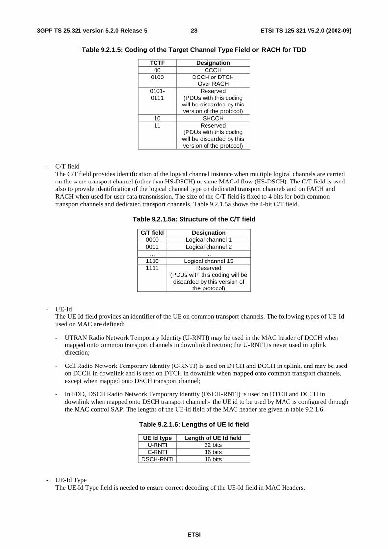
Table 9.2.1.5: Coding of the Target Channel Type Field on RACH for TDD
TCTF Designation 00 CCCH
0100 DCCH or DTCH Over RACH
0101- 0111
Reserved (PDUs with this coding will be discarded by this version of the protocol)
10 SHCCH 11 Reserved
(PDUs with this coding will be discarded by this version of the protocol)
- C/T field The C/T field provides identification of the logical channel instance when multiple logical channels are carried on the same transport channel (other than HS-DSCH) or same MAC-d flow (HS-DSCH). The C/T field is used also to provide identification of the logical channel type on dedicated transport channels and on FACH and RACH when used for user data transmission. The size of the C/T field is fixed to 4 bits for both common transport channels and dedicated transport channels. Table 9.2.1.5a shows the 4-bit C/T field.
Table 9.2.1.5a: Structure of the C/T field
C/T field Designation 0000 Logical channel 1 0001 Logical channel 2
... ... 1110 Logical channel 15 1111 Reserved
(PDUs with this coding will be discarded by this version of
the protocol)
- UE-Id The UE-Id field provides an identifier of the UE on common transport channels. The following types of UE-Id used on MAC are defined:
- UTRAN Radio Network Temporary Identity (U-RNTI) may be used in the MAC header of DCCH when mapped onto common transport channels in downlink direction; the U-RNTI is never used in uplink direction;
- Cell Radio Network Temporary Identity (C-RNTI) is used on DTCH and DCCH in uplink, and may be used on DCCH in downlink and is used on DTCH in downlink when mapped onto common transport channels, except when mapped onto DSCH transport channel;
- In FDD, DSCH Radio Network Temporary Identity (DSCH-RNTI) is used on DTCH and DCCH in downlink when mapped onto DSCH transport channel;- the UE id to be used by MAC is configured through the MAC control SAP. The lengths of the UE-id field of the MAC header are given in table 9.2.1.6.
Table 9.2.1.6: Lengths of UE Id field
UE Id type Length of UE Id field U-RNTI 32 bits C-RNTI 16 bits
DSCH-RNTI 16 bits
- UE-Id Type The UE-Id Type field is needed to ensure correct decoding of the UE-Id field in MAC Headers.
ETSI
ETSI TS 125 321 V5.2.0 (2002-09) 293GPP TS 25.321 version 5.2.0 Release 5
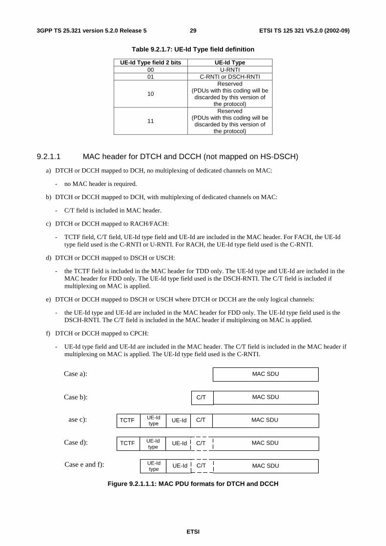
Table 9.2.1.7: UE-Id Type field definition
UE-Id Type field 2 bits UE-Id Type 00 U-RNTI 01 C-RNTI or DSCH-RNTI
10
Reserved (PDUs with this coding will be discarded by this version of
the protocol)
11
Reserved (PDUs with this coding will be discarded by this version of
the protocol)
9.2.1.1 MAC header for DTCH and DCCH (not mapped on HS-DSCH)
a) DTCH or DCCH mapped to DCH, no multiplexing of dedicated channels on MAC:
- no MAC header is required.
b) DTCH or DCCH mapped to DCH, with multiplexing of dedicated channels on MAC:
- C/T field is included in MAC header.
c) DTCH or DCCH mapped to RACH/FACH:
- TCTF field, C/T field, UE-Id type field and UE-Id are included in the MAC header. For FACH, the UE-Id type field used is the C-RNTI or U-RNTI. For RACH, the UE-Id type field used is the C-RNTI.
d) DTCH or DCCH mapped to DSCH or USCH:
- the TCTF field is included in the MAC header for TDD only. The UE-Id type and UE-Id are included in the MAC header for FDD only. The UE-Id type field used is the DSCH-RNTI. The C/T field is included if multiplexing on MAC is applied.
e) DTCH or DCCH mapped to DSCH or USCH where DTCH or DCCH are the only logical channels:
- the UE-Id type and UE-Id are included in the MAC header for FDD only. The UE-Id type field used is the DSCH-RNTI. The C/T field is included in the MAC header if multiplexing on MAC is applied.
f) DTCH or DCCH mapped to CPCH:
- UE-Id type field and UE-Id are included in the MAC header. The C/T field is included in the MAC header if multiplexing on MAC is applied. The UE-Id type field used is the C-RNTI.
UE-Id
UE-Id
Case b):
MAC SDU Case a):
MAC SDU TCTF Case d):
MAC SDU Case e and f): UE-Id type
UE-Id MAC SDU TCTF ase c): UE-Id type
UE-Id type
C/T
C/T
C/T
MAC SDU C/T
Figure 9.2.1.1.1: MAC PDU formats for DTCH and DCCH
ETSI
ETSI TS 125 321 V5.2.0 (2002-09) 303GPP TS 25.321 version 5.2.0 Release 5
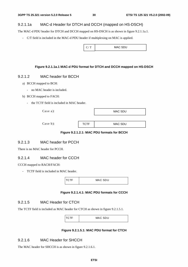
9.2.1.1a MAC-d Header for DTCH and DCCH (mapped on HS-DSCH)
The MAC-d PDU header for DTCH and DCCH mapped on HS-DSCH is as shown in figure 9.2.1.1a.1.
- C/T field is included in the MAC-d PDU header if multiplexing on MAC is applied.
MAC SDUC/T
Figure 9.2.1.1a.1 MAC-d PDU format for DTCH and DCCH mapped on HS-DSCH
9.2.1.2 MAC header for BCCH
a) BCCH mapped to BCH:
- no MAC header is included.
b) BCCH mapped to FACH:
- the TCTF field is included in MAC header.
MAC SDUCase b):
MAC SDUCase a):
TCTF
Figure 9.2.1.2.1: MAC PDU formats for BCCH
9.2.1.3 MAC header for PCCH
There is no MAC header for PCCH.
9.2.1.4 MAC header for CCCH
CCCH mapped to RACH/FACH:
- TCTF field is included in MAC header.
MAC SDUTCTF
Figure 9.2.1.4.1: MAC PDU formats for CCCH
9.2.1.5 MAC Header for CTCH
The TCTF field is included as MAC header for CTCH as shown in figure 9.2.1.5.1.
MAC SDUTCTF
Figure 9.2.1.5.1: MAC PDU format for CTCH
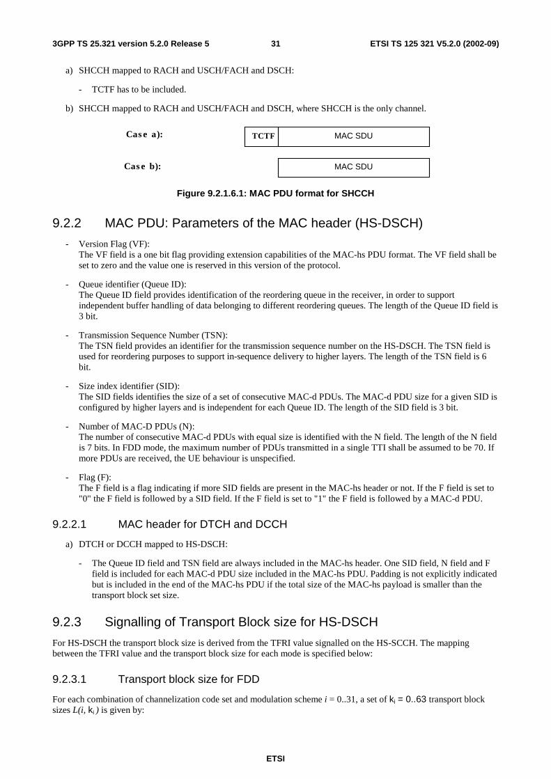
9.2.1.6 MAC Header for SHCCH
The MAC header for SHCCH is as shown in figure 9.2.1.6.1.
ETSI
ETSI TS 125 321 V5.2.0 (2002-09) 313GPP TS 25.321 version 5.2.0 Release 5
a) SHCCH mapped to RACH and USCH/FACH and DSCH:
- TCTF has to be included.
b) SHCCH mapped to RACH and USCH/FACH and DSCH, where SHCCH is the only channel.
MAC SDU
MAC SDUTCTFCase a):
Case b):
Figure 9.2.1.6.1: MAC PDU format for SHCCH
9.2.2 MAC PDU: Parameters of the MAC header (HS-DSCH)
- Version Flag (VF): The VF field is a one bit flag providing extension capabilities of the MAC-hs PDU format. The VF field shall be set to zero and the value one is reserved in this version of the protocol.
- Queue identifier (Queue ID): The Queue ID field provides identification of the reordering queue in the receiver, in order to support independent buffer handling of data belonging to different reordering queues. The length of the Queue ID field is 3 bit.
- Transmission Sequence Number (TSN): The TSN field provides an identifier for the transmission sequence number on the HS-DSCH. The TSN field is used for reordering purposes to support in-sequence delivery to higher layers. The length of the TSN field is 6 bit.
- Size index identifier (SID): The SID fields identifies the size of a set of consecutive MAC-d PDUs. The MAC-d PDU size for a given SID is configured by higher layers and is independent for each Queue ID. The length of the SID field is 3 bit.
- Number of MAC-D PDUs (N): The number of consecutive MAC-d PDUs with equal size is identified with the N field. The length of the N field is 7 bits. In FDD mode, the maximum number of PDUs transmitted in a single TTI shall be assumed to be 70. If more PDUs are received, the UE behaviour is unspecified.
- Flag (F): The F field is a flag indicating if more SID fields are present in the MAC-hs header or not. If the F field is set to "0" the F field is followed by a SID field. If the F field is set to "1" the F field is followed by a MAC-d PDU.
9.2.2.1 MAC header for DTCH and DCCH
a) DTCH or DCCH mapped to HS-DSCH:
- The Queue ID field and TSN field are always included in the MAC-hs header. One SID field, N field and F field is included for each MAC-d PDU size included in the MAC-hs PDU. Padding is not explicitly indicated but is included in the end of the MAC-hs PDU if the total size of the MAC-hs payload is smaller than the transport block set size.
9.2.3 Signalling of Transport Block size for HS-DSCH
For HS-DSCH the transport block size is derived from the TFRI value signalled on the HS-SCCH. The mapping between the TFRI value and the transport block size for each mode is specified below:
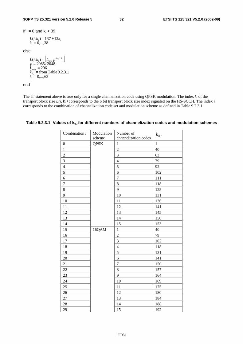
9.2.3.1 Transport block size for FDD
For each combination of channelization code set and modulation scheme i = 0..31, a set of ki = 0..63 transport block sizes L(i, ki ) is given by:
ETSI
ETSI TS 125 321 V5.2.0 (2002-09) 323GPP TS 25.321 version 5.2.0 Release 5
If i = 0 and ki < 39
38,...,012137),(
=+=
i
iik
kkiL
else
63,...,09.2.3.1 Table from
2962048/2085
),(
,0
min
min,0
===
== +
i
i
kki
kkLp
pLkiL ii
end
The 'if' statement above is true only for a single channelization code using QPSK modulation. The index ki of the transport block size L(i, ki ) corresponds to the 6 bit transport block size index signaled on the HS-SCCH. The index i corresponds to the combination of channelization code set and modulation scheme as defined in Table 9.2.3.1.
Table 9.2.3.1: Values of k0,i for different numbers of channelization codes and modulation schemes
Combination i Modulation scheme
Number of channelization codes ik ,0
0 1 1
1 2 40
2 3 63 3 4 79
4 5 92
5 6 102 6 7 111
7 8 118
8 9 125 9 10 131
10 11 136
11 12 141 12 13 145
13 14 150 14
QPSK
15 153
15 1 40
16 2 79 17 3 102
18 4 118
19 5 131 20 6 141
21 7 150
22 8 157 23 9 164
24 10 169
25 11 175 26 12 180
27 13 184
28 14 188 29
16QAM
15 192
ETSI
ETSI TS 125 321 V5.2.0 (2002-09) 333GPP TS 25.321 version 5.2.0 Release 5
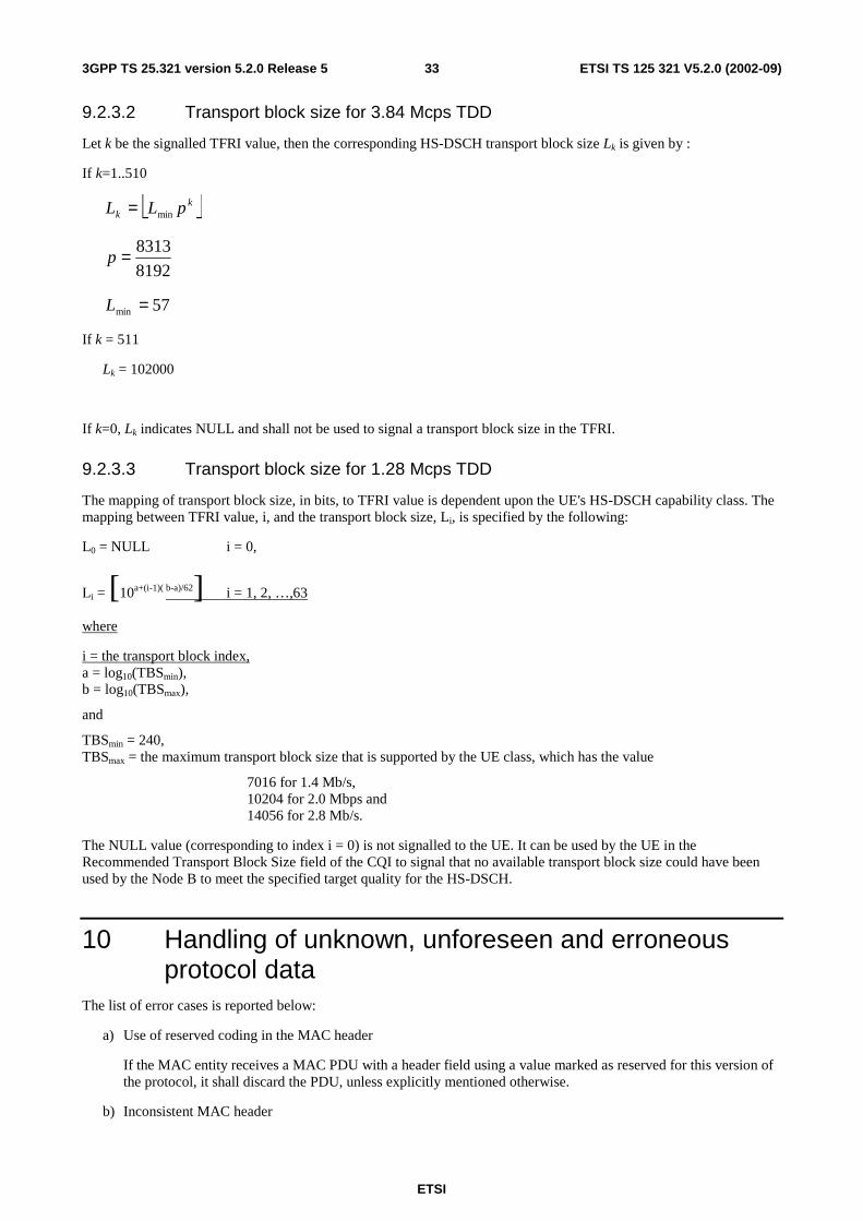
9.2.3.2 Transport block size for 3.84 Mcps TDD
Let k be the signalled TFRI value, then the corresponding HS-DSCH transport block size Lk is given by :
If k=1..510
kk pLL min=
8192
8313=p
57min =L
If k = 511
Lk = 102000
If k=0, Lk indicates NULL and shall not be used to signal a transport block size in the TFRI.
9.2.3.3 Transport block size for 1.28 Mcps TDD
The mapping of transport block size, in bits, to TFRI value is dependent upon the UE's HS-DSCH capability class. The mapping between TFRI value, i, and the transport block size, Li, is specified by the following:
L0 = NULL i = 0,
Li = [10a+(i-1)( b-a)/62] i = 1, 2, …,63
where
i = the transport block index, a = log10(TBSmin), b = log10(TBSmax),
and
TBSmin = 240, TBSmax = the maximum transport block size that is supported by the UE class, which has the value
7016 for 1.4 Mb/s, 10204 for 2.0 Mbps and 14056 for 2.8 Mb/s.
The NULL value (corresponding to index i = 0) is not signalled to the UE. It can be used by the UE in the Recommended Transport Block Size field of the CQI to signal that no available transport block size could have been used by the Node B to meet the specified target quality for the HS-DSCH.
10 Handling of unknown, unforeseen and erroneous protocol data
The list of error cases is reported below:
a) Use of reserved coding in the MAC header
If the MAC entity receives a MAC PDU with a header field using a value marked as reserved for this version of the protocol, it shall discard the PDU, unless explicitly mentioned otherwise.
b) Inconsistent MAC header
ETSI
ETSI TS 125 321 V5.2.0 (2002-09) 343GPP TS 25.321 version 5.2.0 Release 5
If the MAC entity receives a MAC PDU with a header inconsistent with the configuration received from RRC, it shall discard the PDU. E.g.: In case DTCH is mapped to RACH/FACH, the MAC entity shall discard a PDU with a C/T field indicating a logical channel number that is not configured.
c) Erroneous MAC header fields
The MAC PDU shall be discarded if the lower layer gives an error indication for a MAC PDU and a MAC header is included in the MAC PDU.
11 Specific functions
11.1 Traffic volume measurement for dynamic radio bearer control
Dynamic radio bearer control is performed by RRC, based on the traffic volume measurements reported by MAC. Traffic volume information is measured in MAC layer and the results are reported from MAC layer to RRC layer.
At least every TTI, the MAC layer shall receive from each RLC entity the value of its Buffer Occupancy (BO), expressed in bytes. RRC can configure MAC to keep track of statistics (i.e. raw BO, average of BO and variance of BO) on the BO (see [7]) values of all Radio Bearers mapped onto a given transport channel. When the average or variance are requested, an averaging interval duration will also be provided.
Every time the BO values are reported to MAC, the UE shall verify whether an event was triggered or if a periodic report is required (see [7]). If reporting is required (multiple reports may be triggered in a single TTI), the MAC shall deliver to RRC the reporting quantities required for the corresponding RBs. In the case of average and variance of BO, the averaging should be performed for the interval with the configured duration ending at the time when the event was triggered.
RRC requests MAC measurement report with the primitive CMAC-Measure-REQ including following parameters.
Measurement information elements.
- Reporting Quantity identifiers Indicates what should be reported to RRC layer For each RB, BO (optional), Average of BO (optional), or Variance of BO(optional)
- Time interval to take an average or a variance (applicable when Average or Variance is Reporting Quantity) Indicates time interval to take an average or a variance of BO The calculation of average and variance of BO shall be based on one sample of BO per 10ms during the time interval given in this information element. All samples taken in the time interval shall have equal weight in the calculation.
MAC receives RLC PDUs with the primitive MAC-Data-REQ including following parameters.
- Buffer Occupancy (BO) The parameter Buffer Occupancy (BO) indicates for each logical channel the amount of data in number of bytes that is available for transmission and retransmission in RLC layer. When MAC is connected to an AM RLC entity, control PDUs to be transmitted and RLC PDUs outside the RLC Tx window shall also be included in the BO. RLC PDUs that have been transmitted but not negatively acknowledged by the peer entity shall not be included in the BO.
11.2 Control of RACH transmissions The MAC sublayer is in charge of controlling the timing of RACH transmissions on transmission time interval level (the timing on access slot level is controlled by L1). Note that retransmissions in case of erroneously received RACH message part are under control of higher layers, i.e. RLC, or RRC for CCCH (and SHCCH for TDD).
ETSI
ETSI TS 125 321 V5.2.0 (2002-09) 353GPP TS 25.321 version 5.2.0 Release 5
11.2.1 Access Service Class selection
The physical RACH resources (i.e. access slots and preamble signatures for FDD, timeslot and channelisation code for 3.84 Mcps TDD, SYNC1 code for 1.28 Mcps TDD) may be divided between different Access Service Classes in order to provide different priorities of RACH usage. It is possible for more than one ASC or for all ASCs to be assigned to the same access slot/signature space or SYNC1 code.
Access Service Classes are numbered in the range 0 ≤ i ≤ NumASC ≤ 7 (i.e. the maximum number of ASCs is 8). An ASC is defined by an identifier i that defines a certain partition of the PRACH resources and an associated persistence value Pi. A set of ASC parameters consists of NumASC+1 such parameters (i, Pi), i = 0, …, NumASC. The PRACH partitions and the persistence values Pi are derived by the RRC protocol from system information (see [7]). The set of ASC parameters is provided to MAC with the CMAC-Config-REQ primitive. The ASC enumeration is such that it corresponds to the order of priority (ASC 0 = highest priority, ASC 7 = lowest priority). ASC 0 shall be used in case of Emergency Call or for reasons with equivalent priority.
At radio bearer setup/reconfiguration each involved logical channel is assigned a MAC Logical channel Priority (MLP) in the range 1,…,8. When the MAC sublayer is configured for RACH transmission in the UE, these MLP levels shall be employed for ASC selection on MAC.
The following ASC selection scheme shall be applied, where NumASC is the highest available ASC number and MinMLP the highest logical channel priority assigned to one logical channel:
- in case all TBs in the TB set have the same MLP, select ASC = min(NumASC, MLP);
- in case TBs in a TB set have different priority, determine the highest priority level MinMLP and select ASC = min(NumASC, MinMLP).
When an RRC CONNECTION REQUEST message is sent RRC determines ASC by means of the access class [7]. The ASC to be used in these circumstances is signalled to MAC by means of the CMAC-CONFIG-REQ message.
If MAC has knowledge of a U-RNTI then the ASC is determined in the MAC entity. If no U-RNTI has been indicated to MAC then MAC will use the ASC indicated in the CMAC-CONFIG-REQ primitive.
11.2.2 Control of RACH transmissions for FDD mode
The RACH transmissions are controlled by the UE MAC sublayer as outlined in figure 11.2.2.1.
NOTE: The figure shall illustrate the operation of the transmission control procedure as specified below. It shall not impose restrictions on implementation. MAC controls the timing of each initial preamble ramping cycle as well as successive preamble ramping cycles in case that none or a negative acknowledgement is received on AICH.
NOTE: In Cell-FACH state, the UE should co-ordinate the UL transmission schedule with the measurement schedule in FACH measurement occasions so as to minimise any delays associated with inter-frequency measurements.
MAC receives the following RACH transmission control parameters from RRC with the CMAC-CONFIG-Req primitive:
- a set of Access Service Class (ASC) parameters, which includes for each ASC, i=0,…,NumASC an identification of a PRACH partition and a persistence value Pi (transmission probability);
- maximum number of preamble ramping cycles Mmax;
- range of backoff interval for timer TBO1, given in terms of numbers of transmission 10 ms time intervals NBO1max and NBO1min, applicable when negative acknowledgement on AICH is received.
When there is data to be transmitted, MAC selects the ASC from the available set of ASCs, which consists of an identifier i of a certain PRACH partition and an associated persistence value Pi. The procedure to be applied for ASC selection is described in subclause 11.2.1.
Based on the persistence value Pi, the UE decides whether to start the L1 PRACH transmission procedure (see [13]) in the present transmission time interval or not. If transmission is allowed, the PRACH transmission procedure (starting with a preamble power ramping cycle) is initiated by sending of a PHY-ACCESS-REQ primitive. MAC then waits for
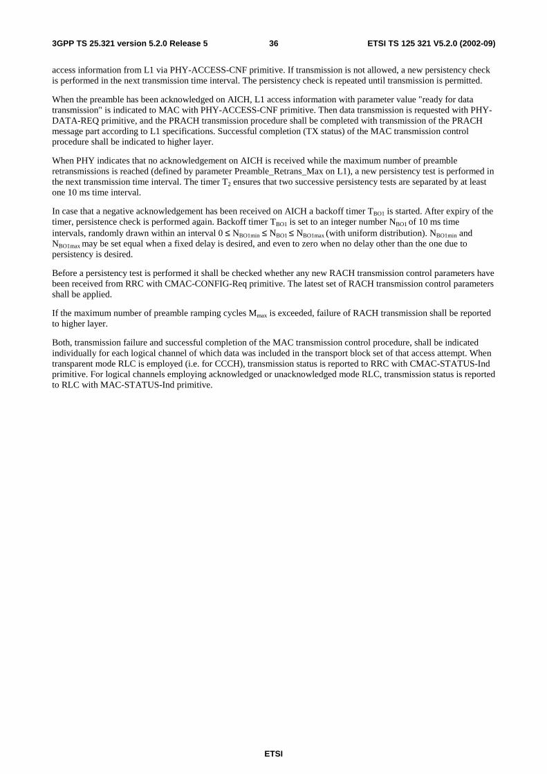
ETSI
ETSI TS 125 321 V5.2.0 (2002-09) 363GPP TS 25.321 version 5.2.0 Release 5
access information from L1 via PHY-ACCESS-CNF primitive. If transmission is not allowed, a new persistency check is performed in the next transmission time interval. The persistency check is repeated until transmission is permitted.
When the preamble has been acknowledged on AICH, L1 access information with parameter value "ready for data transmission" is indicated to MAC with PHY-ACCESS-CNF primitive. Then data transmission is requested with PHY-DATA-REQ primitive, and the PRACH transmission procedure shall be completed with transmission of the PRACH message part according to L1 specifications. Successful completion (TX status) of the MAC transmission control procedure shall be indicated to higher layer.
When PHY indicates that no acknowledgement on AICH is received while the maximum number of preamble retransmissions is reached (defined by parameter Preamble_Retrans_Max on L1), a new persistency test is performed in the next transmission time interval. The timer T2 ensures that two successive persistency tests are separated by at least one 10 ms time interval.
In case that a negative acknowledgement has been received on AICH a backoff timer TBO1 is started. After expiry of the timer, persistence check is performed again. Backoff timer TBO1 is set to an integer number NBO1 of 10 ms time intervals, randomly drawn within an interval 0 ≤ NBO1min ≤ NBO1 ≤ NBO1max (with uniform distribution). NBO1min and NBO1max may be set equal when a fixed delay is desired, and even to zero when no delay other than the one due to persistency is desired.
Before a persistency test is performed it shall be checked whether any new RACH transmission control parameters have been received from RRC with CMAC-CONFIG-Req primitive. The latest set of RACH transmission control parameters shall be applied.
If the maximum number of preamble ramping cycles Mmax is exceeded, failure of RACH transmission shall be reported to higher layer.
Both, transmission failure and successful completion of the MAC transmission control procedure, shall be indicated individually for each logical channel of which data was included in the transport block set of that access attempt. When transparent mode RLC is employed (i.e. for CCCH), transmission status is reported to RRC with CMAC-STATUS-Ind primitive. For logical channels employing acknowledged or unacknowledged mode RLC, transmission status is reported to RLC with MAC-STATUS-Ind primitive.
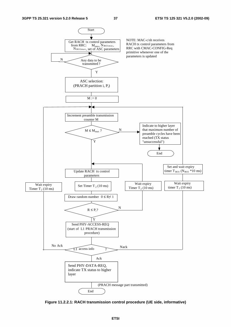
ETSI
ETSI TS 125 321 V5.2.0 (2002-09) 373GPP TS 25.321 version 5.2.0 Release 5
Increment preamble transmission counter M
Send PHY-ACCESS-REQ ( start of L1 PRACH transmission
procedure)
M ≤ M max ? N
Y
Indicate to higher layer that maximum number of preamble cycles have been reached (TX status "unsuccessful")
L1 access info ? N ack
Ack
(PRACH message part transmitted)
No Ack
End
Draw random number 0 ≤ Ri < 1
R ≤ Pi ? N
Y
Wait expiry Timer T 2 (10 ms)
Set and wait expiry timer T BO1 (N BO1 *10 ms)
M := 0
Start
Get RACH tx control parameters from RRC: M max , N BO1min ,
N BO1max , set of ASC parameters
N Any data to be transmitted ?
Y
NOTE: MAC-c/sh receives RACH tx control parameters from RRC with CMAC-CONFIG-Req primitive whenever one of the parameters is updated
Update RACH tx control parameters
Wait expiry Timer T 2 (10 ms)
Wait expiry timer T 2 (10 ms) Set Timer T 2 (10 ms)
Send PHY-DATA-REQ, indicate TX status to higher layer
ASC selection: (PRACH partition i, Pi)
End
Figure 11.2.2.1: RACH transmission control procedure (UE side, informative)
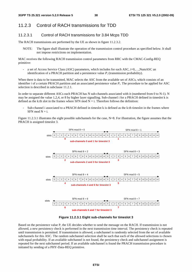
ETSI
ETSI TS 125 321 V5.2.0 (2002-09) 383GPP TS 25.321 version 5.2.0 Release 5
11.2.3 Control of RACH transmissions for TDD
11.2.3.1 Control of RACH transmissions for 3.84 Mcps TDD
The RACH transmissions are performed by the UE as shown in figure 11.2.3.2.
NOTE: The figure shall illustrate the operation of the transmission control procedure as specified below. It shall not impose restrictions on implementation.
MAC receives the following RACH transmission control parameters from RRC with the CMAC-Config-REQ primitive:
- a set of Access Service Class (ASC) parameters, which includes for each ASC, i=0,…,NumASC an identification of a PRACH partition and a persistence value Pi (transmission probability).
When there is data to be transmitted, MAC selects the ASC from the available set of ASCs, which consists of an identifier i of a certain PRACH partition and an associated persistence value Pi. The procedure to be applied for ASC selection is described in subclause 11.2.1.
In order to separate different ASCs each PRACH has N sub-channels associated with it (numbered from 0 to N-1). N may be assigned the value 1,2,4, or 8 by higher layer signalling. Sub-channel i for a PRACH defined in timeslot k is defined as the k:th slot in the frames where SFN mod N = i. Therefore follows the definition:
- Sub-channel i associated to a PRACH defined in timeslot k is defined as the k:th timeslot in the frames where SFN mod N = i.
Figure 11.2.3.1 illustrates the eight possible subchannels for the case, N=8. For illustration, the figure assumes that the PRACH is assigned timeslot 3.
slots
0 1 2 3 4 5 6 7 8 9 11 12 13 1410 0 1 2 3 4 5 6 7 8 9 11 12 13 1410slots
sub-channels 0 and 1 for timeslot 30
0 1 2 3 4 5 6 7 8 9 11 12 13 1410 0 1 2 3 4 5 6 7 8 9 11 12 13 1410
1
32sub-channels 2 and 3 for timeslot 3
SFN mod 8 = 0 SFN mod 8 = 1
SFN mod 8 = 2 SFN mod 8 = 3
0 1 2 3 4 5 6 7 8 9 11 12 13 1410 0 1 2 3 4 5 6 7 8 9 11 12 13 1410
54sub-channels 4 and 5 for timeslot 3
SFN mod 8 = 4 SFN mod 8 = 5
slots
slots0 1 2 3 4 5 6 7 8 9 11 12 13 1410 0 1 2 3 4 5 6 7 8 9 11 12 13 1410
76sub-channels 6 and 7 for timeslot 3
SFN mod 8 = 6 SFN mod 8 = 7
Figure 11.2.3.1 Eight sub-channels for timeslot 3
Based on the persistence value P, the UE decides whether to send the message on the RACH. If transmission is not allowed, a new persistency check is performed in the next transmission time interval. The persistency check is repeated until transmission is permitted. If transmission is allowed, a subchannel is randomly selected from the set of available subchannels for this ASC. The random subchannel selection shall be such that each of the allowed selections is chosen with equal probability. If an available subchannel is not found, the persistency check and subchannel assignment is repeated for the next subchannel period. If an available subchannel is found the PRACH transmission procedure is initiated by sending of a PHY-Data-REQ primitive.
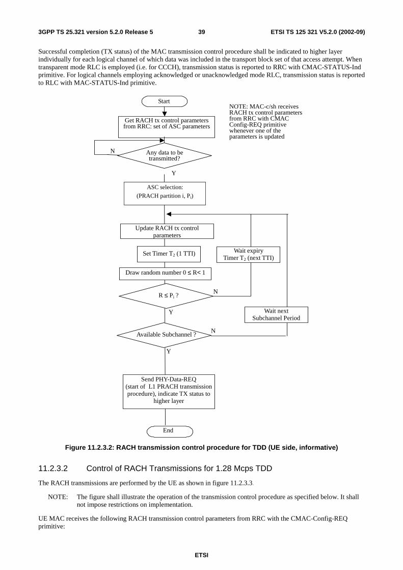
ETSI
ETSI TS 125 321 V5.2.0 (2002-09) 393GPP TS 25.321 version 5.2.0 Release 5
Successful completion (TX status) of the MAC transmission control procedure shall be indicated to higher layer individually for each logical channel of which data was included in the transport block set of that access attempt. When transparent mode RLC is employed (i.e. for CCCH), transmission status is reported to RRC with CMAC-STATUS-Ind primitive. For logical channels employing acknowledged or unacknowledged mode RLC, transmission status is reported to RLC with MAC-STATUS-Ind primitive.
Start
Get RACH tx control parameters from RRC: set of ASC parameters
N Any data to be transmitted?
Y
Send PHY-Data-REQ (start of L1 PRACH transmission procedure), indicate TX status to
higher layer
Draw random number 0 ≤ R< 1
R ≤ Pi ? N
Y
Wait expiry Timer T2 (next TTI)
Update RACH tx control parameters
Set Timer T2 (1 TTI)
NOTE: MAC-c/sh receives RACH tx control parameters from RRC with CMAC Config-REQ primitive whenever one of the parameters is updated
ASC selection:
(PRACH partition i, Pi)
End
Available Subchannel ? N
Y
Wait next Subchannel Period
Figure 11.2.3.2: RACH transmission control procedure for TDD (UE side, informative)
11.2.3.2 Control of RACH Transmissions for 1.28 Mcps TDD
The RACH transmissions are performed by the UE as shown in figure 11.2.3.3.
NOTE: The figure shall illustrate the operation of the transmission control procedure as specified below. It shall not impose restrictions on implementation.
UE MAC receives the following RACH transmission control parameters from RRC with the CMAC-Config-REQ primitive:
ETSI
ETSI TS 125 321 V5.2.0 (2002-09) 403GPP TS 25.321 version 5.2.0 Release 5
- a set of Access Service Class (ASC) parameters, which includes for each ASC, i=0,…,NumASC an identification of a PRACH partition and a persistence value Pi (transmission probability),
- maximum number of synchronisation attempts Mmax.
When there is data to be transmitted, MAC selects the ASC from the available set of ASCs, which consists of an identifier i of a certain PRACH partition and an associated persistence value Pi.
Based on the persistence value Pi, MAC decides whether to start the L1 PRACH procedure in the present transmission time interval or not. If transmission is allowed, the PRACH transmission procedure (starting with the SYNC_UL/FPACH power ramping sequence) is initiated by the sending of a PHY-ACCESS-REQ primitive. MAC then waits for access information from L1 via the PHY-ACCESS-CNF primitive. If transmission is not allowed, a new persistency check is performed in the next transmission time interval. The persistency check is repeated until transmission is permitted.
If a synchronisation burst has been acknowledged on its associated FPACH, PHY will inform MAC by a PHY-ACCESS-CNF primitive indicating "ready for RACH data transmission". Then MAC requests data transmission with a PHY-DATA-REQ primitive, and the PRACH transmission procedure will be completed with transmission on the PRACH resources associated with the FPACH.
Successful completion of the MAC procedure is indicated to higher layer individually for each logical channel of which data was included in the transport block set of that access attempt. When transparent mode RLC is employed (i.e. for CCCH), transmission status is reported to RRC with CMAC-STATUS-Ind primitive. For logical channels employing acknowledged or unacknowledged mode RLC, transmission status is reported to RLC with MAC-STATUS-Ind primitive.
If no synchronisation burst received an acknowledgement on the FPACH within the maximum number of transmissions permitted in a power ramping cycle, PHY will inform MAC by a PHY-ACCESS-CNF primitive indicating "no response received on FPACH". If the maximum number of synchronisation attempts permitted, Mmax, has not been exceeded, then MAC commences a new persistency test sequence in the next transmission time interval and the PHY-ACCESS-REQ procedure is repeated. The timer T2 ensures that two successive persistency tests are separated by at least one transmission time interval. If the maximum number of synchronisation attempts is exceeded then MAC abandons the RACH procedure. Failure to complete the MAC procedure is indicated to higher layer by the CMAC-STATUS-Ind or MAC-STATUS-Ind primitives.
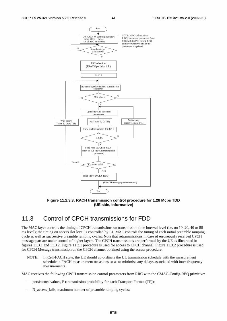
ETSI
ETSI TS 125 321 V5.2.0 (2002-09) 413GPP TS 25.321 version 5.2.0 Release 5
Increment synchronisation transmissioncounter M
Send PHY-ACCESS-REQ(start of L1 PRACH transmission
procedure)
M ≤ Mmax ? N
Y
L1 access info?
Ack
(PRACH message part transmitted)
No Ack
End
Draw random number 0 ≤ Ri< 1
R ≤ Pi?N
Y
Wait expiryTimer T2 (next TTI)
M := 0
Start
Get RACH tx control parametersfrom RRC: Mmax,
set of ASC parameters
N Any data to betransmitted ?
Y
NOTE: MAC-c/sh receivesRACH tx control parameters fromRRC with CMAC Config-REQprimitive whenever one of theparameters is updated
Update RACH tx controlparameters
Wait expiryTimer T2 (next TTI)
Set Timer T 2 (1 TTI)
Send PHY-DATA-REQ
ASC selection:(PRACH partition i, Pi)
Figure 11.2.3.3: RACH transmission control procedure for 1.28 Mcps TDD (UE side, informative)
11.3 Control of CPCH transmissions for FDD The MAC layer controls the timing of CPCH transmissions on transmission time interval level (i.e. on 10, 20, 40 or 80 ms level); the timing on access slot level is controlled by L1. MAC controls the timing of each initial preamble ramping cycle as well as successive preamble ramping cycles. Note that retransmissions in case of erroneously received CPCH message part are under control of higher layers. The CPCH transmissions are performed by the UE as illustrated in figures 11.3.1 and 11.3.2. Figure 11.3.1 procedure is used for access to CPCH channel. Figure 11.3.2 procedure is used for CPCH Message transmission on the CPCH channel obtained using the access procedure.
NOTE: In Cell-FACH state, the UE should co-ordinate the UL transmission schedule with the measurement schedule in FACH measurement occasions so as to minimise any delays associated with inter-frequency measurements.
MAC receives the following CPCH transmission control parameters from RRC with the CMAC-Config-REQ primitive:
- persistence values, P (transmission probability for each Transport Format (TF));
- N_access_fails, maximum number of preamble ramping cycles;
ETSI
ETSI TS 125 321 V5.2.0 (2002-09) 423GPP TS 25.321 version 5.2.0 Release 5
- NF_max, maximum number of frames for CPCH transmission for each TF;
- N_EOT (Number of EOT for release of CPCH transmission);
- Backoff control timer parameters;
- Transport Format Set;
- Initial Priority Delays;
- Channel Assignment Active indication.
The MAC procedure for CPCH access shall be invoked when the UE has data to transmit. The steps for this procedure are listed here:
1. the UE shall get all UL transmit parameters (CPCH Set Info, P values, Initial Priority Delays, N_access_fails, NF_max, N_EOT etc) from RRC;
2. the UE shall reset counter M, EOT counter and Frame Count Transmitted (FCT) upon entry to the initial access procedure;
3. if counter M is equal to N_access_fails, the UE shall indicate an access failure error to higher layer and the CPCH access procedure ends. Access failure is reported to RLC with MAC-STATUS-Ind primitive individually for each logical channel of which data was included in the transport block set that could not be transmitted. If counter M is less than N_access_fails, the UE shall send a PHY-CPCH_Status-REQ to Layer 1 to obtain CPCH TF subset status. If Layer 1 returns an error message, the UE shall increment counter M and the procedure shall continue from step 3. If Layer 1 returns a PHY-CPCH_Status-CNF message, which includes a TF subset indicating the currently available TFs of the requested TF subset, the procedure shall continue from step 4;
4. the UE shall initialise the Busy Table with the CPCH TF subset status from Layer 1. Those TFs in the TF subset of the Layer 1 PHY-CPCH_Status-CNF response will be marked available. All other TFs will be marked busy;
5. if all TFs are not marked busy, the procedure shall proceed from step 6. If all TFs are marked busy, the UE shall reset and start timer Tboc1, wait until timer expiry, and increment counter M. The procedure shall continue from step 3;
6. the UE shall update all UL transmit parameters from RRC;
7. UE shall select a TF from the set of available TFs listed in the Busy Table. UE shall use the CPCH channel capacity (transport block set size, NF_max, and TTI interval), and Busy Table information to select one CPCH TF for L1 to access. The UE may select a TF, which uses a lower data rate and a lower UL Tx power than the maximum UL Tx power allowed. UE shall implement a test based on the Persistence value (P) to determine whether to attempt access to the selected CPCH TF. If access is allowed, the procedure shall continue from step 9. If the P test does not allow access, the procedure shall continue from step 8;
8. the selected CPCH TF shall be marked busy in the Busy Table. If all TFs are marked busy, the UE shall reset and start timer Tboc1, wait until timer expiry, increment counter M, and continue from step 3. If all TFs are not marked busy, the UE shall resume the procedure from step 6;
9. the UE may implement an initial delay based on ASC of the data to be transmitted, then shall send a PHY-Access-REQ with the selected TF to L1 for CPCH access. After the UE has sent the access request to L1 , L1 shall return a PHY-Access-CNF including one of five access indications to MAC as shown in figure 11.3.1. If the L1 access indication is that access is granted, then UE shall continue from step 14. For the cases of the other Layer 1 responses, the procedure shall continue from step 10, 11, or 12 respectively.
10. if L1 access indication is no AP-AICH received or no CD-AICH received, the UE shall reset and start timer Tboc3, wait until timer expiry, and increment counter M. The UE shall proceed from step 3;
11. if L1 access indication is AP-AICH_nak received, the UE shall reset and start timer Tboc2, wait until timer expiry. If Channel Assignment (CA) is active, the UE shall proceed from step 13. If Channel Assignment (CA) is not active, the procedure shall continue from step 8;
12. if L1 access indication is CD-AICH signature mismatch, the UE shall reset and start timer Tboc4, wait until timer expiry, and increment counter M. The procedure shall continue from step 3;
13. the UE shall increment counter M. The procedure shall continue from step 3.
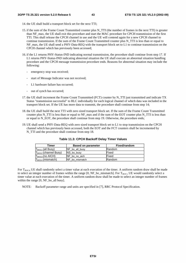
ETSI
ETSI TS 125 321 V5.2.0 (2002-09) 433GPP TS 25.321 version 5.2.0 Release 5
14. the UE shall build a transport block set for the next TTI;
15. if the sum of the Frame Count Transmitted counter plus N_TTI (the number of frames in the next TTI) is greater than NF_max, the UE shall exit this procedure and start the MAC procedure for CPCH transmission of the first TTI. This shall release the CPCH channel in use and the UE will contend again for a new CPCH channel to continue transmission. If the sum of the Frame Count Transmitted counter plus N_TTI is less than or equal to NF_max, the UE shall send a PHY-Data-REQ with the transport block set to L1 to continue transmission on the CPCH channel which has previously been accessed;
16. if the L1 returns PHY-Status-IND indicating normal transmission, the procedure shall continue from step 17. If L1 returns PHY-Status-IND indicating abnormal situation the UE shall execute an abnormal situation handling procedure and the CPCH message transmission procedure ends. Reasons for abnormal situation may include the following:
- emergency stop was received;
- start of Message Indicator was not received;
- L1 hardware failure has occurred;
- out of synch has occurred;
17. the UE shall increment the Frame Count Transmitted (FCT) counter by N_TTI just transmitted and indicate TX Status "transmission successful" to RLC individually for each logical channel of which data was included in the transport block set. If the UE has more data to transmit, the procedure shall continue from step 14;
18. the UE shall build the next TTI with zero sized transport block set. If the sum of the Frame Count Transmitted counter plus N_TTI is less than or equal to NF_max and if the sum of the EOT counter plus N_TTI is less than or equal to N_EOT, the procedure shall continue from step 19. Otherwise, the procedure ends;
19. UE shall send a PHY-Data-REQ with zero sized transport block set to L1 to stop transmission on the CPCH channel which has previously been accessed, both the EOT and the FCT counters shall be incremented by N_TTI and the procedure shall continue from step 18.
Table 11.3: CPCH Backoff Delay Timer Values
Timer Based on parameter Fixed/random TBOC1 (all Busy) NF_bo_all_busy Random TBOC2 (channel Busy) NS_bo_busy Fixed TBOC3 (no AICH) NF_bo_no_aich Fixed TBOC4 (mismatch) NF_bo_mismatch Random
For TBOC4, UE shall randomly select a timer value at each execution of the timer. A uniform random draw shall be made to select an integer number of frames within the range [0, NF_bo_mismatch]. For TBOC1, UE would randomly select a timer value at each execution of the timer. A uniform random draw shall be made to select an integer number of frames within the range [0, NF_bo_all busy].
NOTE: Backoff parameter range and units are specified in [7], RRC Protocol Specification.
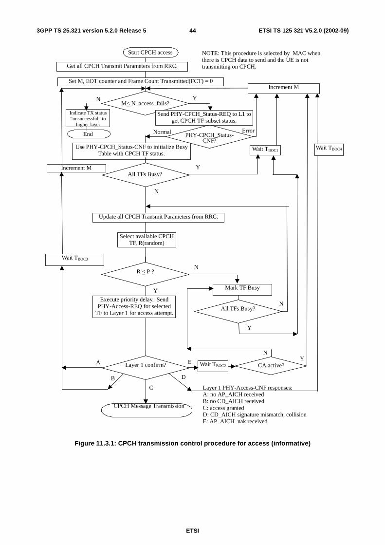
ETSI
ETSI TS 125 321 V5.2.0 (2002-09) 443GPP TS 25.321 version 5.2.0 Release 5
Start CPCH access
Execute priority delay. SendPHY-Access-REQ for selected
TF to Layer 1 for access attempt.
Use PHY-CPCH_Status-CNF to initialize BusyTable with CPCH TF status.
Update all CPCH Transmit Parameters from RRC.
YAll TFs Busy?
N
Select available CPCHTF, R(random)
NR < P ?
Y
Wait TBOC1 Wait TBOC4
Wait TBOC2
B
Layer 1 confirm?A
Mark TF Busy
NAll TFs Busy?
Y
Wait TBOC3
E
D
C Layer 1 PHY-Access-CNF responses:A: no AP_AICH receivedB: no CD_AICH receivedC: access grantedD: CD_AICH signature mismatch, collisionE: AP_AICH_nak received
Set M, EOT counter and Frame Count Transmitted(FCT) = 0Increment M
Increment M
NM< N_access_fails?
Y
NOTE: This procedure is selected by MAC whenthere is CPCH data to send and the UE is nottransmitting on CPCH.
Normal PHY-CPCH_Status-CNF?
Error
Send PHY-CPCH_Status-REQ to L1 toget CPCH TF subset status.
NY
Get all CPCH Transmit Parameters from RRC.
CA active?
CPCH Message Transmission
Indicate TX status“unsuccessful” to
higher layer
End
Figure 11.3.1: CPCH transmission control procedure for access (informative)
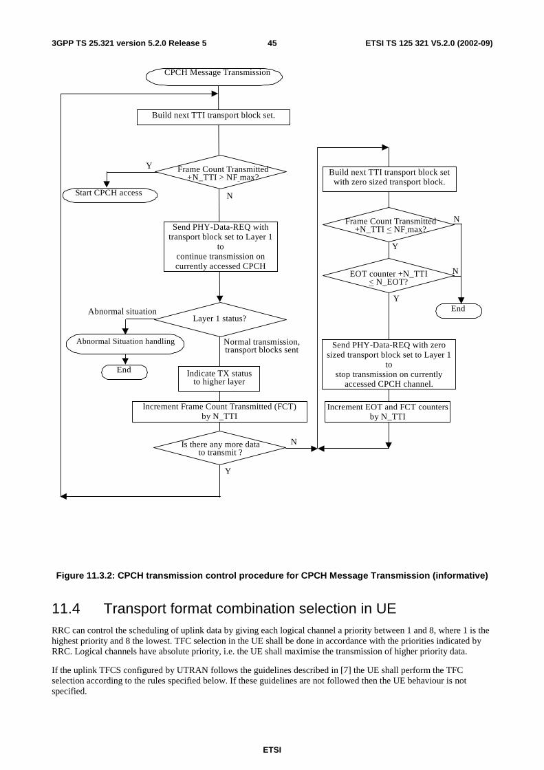
ETSI
ETSI TS 125 321 V5.2.0 (2002-09) 453GPP TS 25.321 version 5.2.0 Release 5
CPCH Message Transmission
Send PHY-Data-REQ withtransport block set to Layer 1
tocontinue transmission oncurrently accessed CPCH
Y Frame Count Transmitted+N_TTI > NF max?
N
Build next TTI transport block set.
Abnormal Situation handling
Layer 1 status?Abnormal situation
Increment Frame Count Transmitted (FCT)by N_TTI
Start CPCH access
Normal transmission,transport blocks sent
Is there any more datato transmit ?
Y
N
End
Build next TTI transport block setwith zero sized transport block.
EOT counter +N_TTI < N_EOT?
NFrame Count Transmitted+N_TTI < NF max?
Y
Y
Send PHY-Data-REQ with zerosized transport block set to Layer 1
tostop transmission on currently
accessed CPCH channel.
Increment EOT and FCT countersby N_TTI
N
Indicate TX statusto higher layer
End
Figure 11.3.2: CPCH transmission control procedure for CPCH Message Transmission (informative)
11.4 Transport format combination selection in UE RRC can control the scheduling of uplink data by giving each logical channel a priority between 1 and 8, where 1 is the highest priority and 8 the lowest. TFC selection in the UE shall be done in accordance with the priorities indicated by RRC. Logical channels have absolute priority, i.e. the UE shall maximise the transmission of higher priority data.
If the uplink TFCS configured by UTRAN follows the guidelines described in [7] the UE shall perform the TFC selection according to the rules specified below. If these guidelines are not followed then the UE behaviour is not specified.
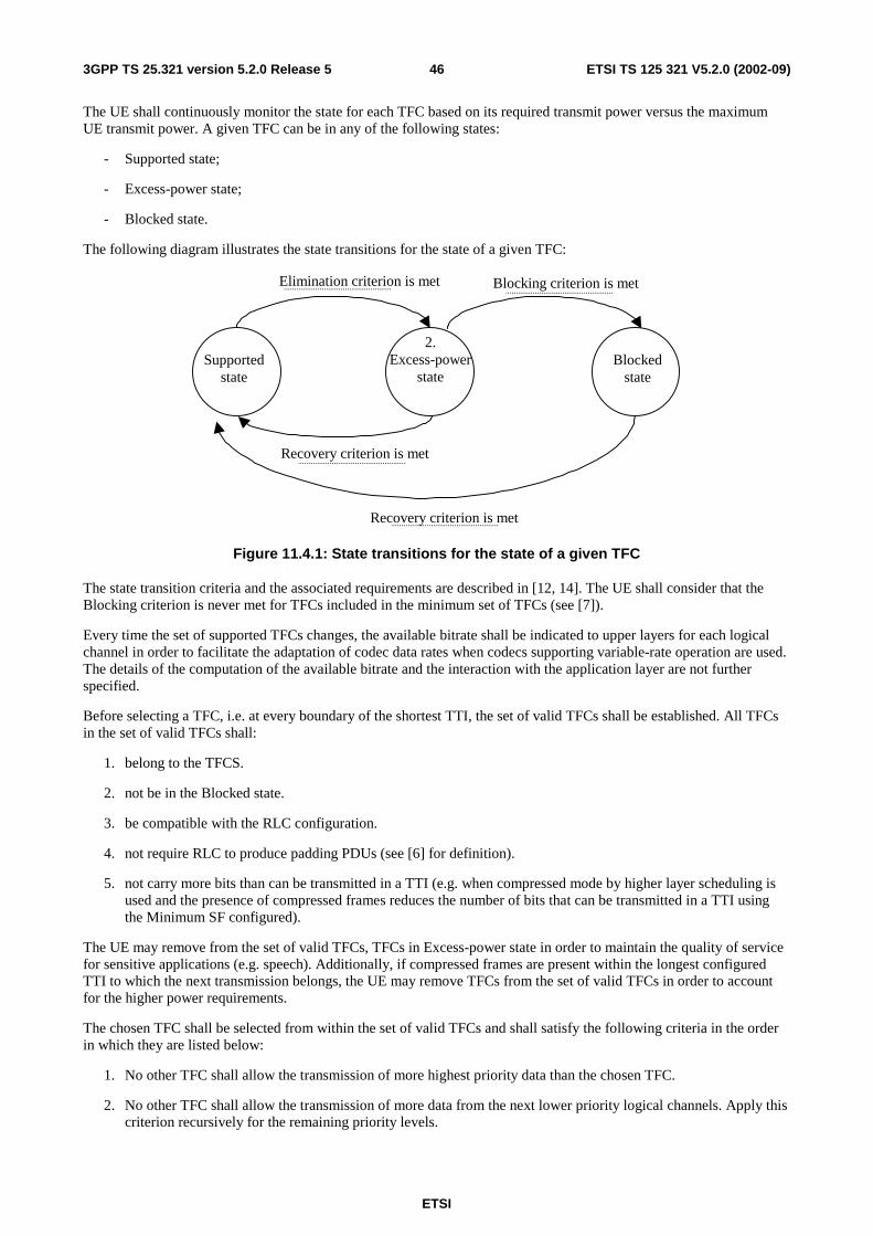
ETSI
ETSI TS 125 321 V5.2.0 (2002-09) 463GPP TS 25.321 version 5.2.0 Release 5
The UE shall continuously monitor the state for each TFC based on its required transmit power versus the maximum UE transmit power. A given TFC can be in any of the following states:
- Supported state;
- Excess-power state;
- Blocked state.
The following diagram illustrates the state transitions for the state of a given TFC:
2. Excess-power
state Supported
state
Elimination criterion is met
Recovery criterion is met
Blocked state
Blocking criterion is met
Recovery criterion is met
Figure 11.4.1: State transitions for the state of a given TFC
The state transition criteria and the associated requirements are described in [12, 14]. The UE shall consider that the Blocking criterion is never met for TFCs included in the minimum set of TFCs (see [7]).
Every time the set of supported TFCs changes, the available bitrate shall be indicated to upper layers for each logical channel in order to facilitate the adaptation of codec data rates when codecs supporting variable-rate operation are used. The details of the computation of the available bitrate and the interaction with the application layer are not further specified.
Before selecting a TFC, i.e. at every boundary of the shortest TTI, the set of valid TFCs shall be established. All TFCs in the set of valid TFCs shall:
1. belong to the TFCS.
2. not be in the Blocked state.
3. be compatible with the RLC configuration.
4. not require RLC to produce padding PDUs (see [6] for definition).
5. not carry more bits than can be transmitted in a TTI (e.g. when compressed mode by higher layer scheduling is used and the presence of compressed frames reduces the number of bits that can be transmitted in a TTI using the Minimum SF configured).
The UE may remove from the set of valid TFCs, TFCs in Excess-power state in order to maintain the quality of service for sensitive applications (e.g. speech). Additionally, if compressed frames are present within the longest configured TTI to which the next transmission belongs, the UE may remove TFCs from the set of valid TFCs in order to account for the higher power requirements.
The chosen TFC shall be selected from within the set of valid TFCs and shall satisfy the following criteria in the order in which they are listed below:
1. No other TFC shall allow the transmission of more highest priority data than the chosen TFC.
2. No other TFC shall allow the transmission of more data from the next lower priority logical channels. Apply this criterion recursively for the remaining priority levels.
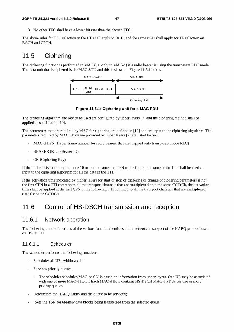
ETSI
ETSI TS 125 321 V5.2.0 (2002-09) 473GPP TS 25.321 version 5.2.0 Release 5
3. No other TFC shall have a lower bit rate than the chosen TFC.
The above rules for TFC selection in the UE shall apply to DCH, and the same rules shall apply for TF selection on RACH and CPCH.
11.5 Ciphering The ciphering function is performed in MAC (i.e. only in MAC-d) if a radio bearer is using the transparent RLC mode. The data unit that is ciphered is the MAC SDU and this is shown in Figure 11.5.1 below.
MAC SDUC/TUE-Id
MAC header MAC SDU
TCTF UE-Idtype
Ciphering Unit
Figure 11.5.1: Ciphering unit for a MAC PDU
The ciphering algorithm and key to be used are configured by upper layers [7] and the ciphering method shall be applied as specified in [10].
The parameters that are required by MAC for ciphering are defined in [10] and are input to the ciphering algorithm. The parameters required by MAC which are provided by upper layers [7] are listed below:
- MAC-d HFN (Hyper frame number for radio bearers that are mapped onto transparent mode RLC)
- BEARER (Radio Bearer ID)
- CK (Ciphering Key)
If the TTI consists of more than one 10 ms radio frame, the CFN of the first radio frame in the TTI shall be used as input to the ciphering algorithm for all the data in the TTI.
If the activation time indicated by higher layers for start or stop of ciphering or change of ciphering parameters is not the first CFN in a TTI common to all the transport channels that are multiplexed onto the same CCTrCh, the activation time shall be applied at the first CFN in the following TTI common to all the transport channels that are multiplexed onto the same CCTrCh.
11.6 Control of HS-DSCH transmission and reception
11.6.1 Network operation
The following are the functions of the various functional entities at the network in support of the HARQ protocol used on HS-DSCH.
11.6.1.1 Scheduler
The scheduler performs the following functions:
- Schedules all UEs within a cell;
- Services priority queues:
- The scheduler schedules MAC-hs SDUs based on information from upper layers. One UE may be associated with one or more MAC-d flows. Each MAC-d flow contains HS-DSCH MAC-d PDUs for one or more priority queues.
- Determines the HARQ Entity and the queue to be serviced;
- Sets the TSN for the new data blocks being transferred from the selected queue;
ETSI
ETSI TS 125 321 V5.2.0 (2002-09) 483GPP TS 25.321 version 5.2.0 Release 5
- set the TSN to value 0 for the first MAC-hs PDU transmitted for one HS-DSCH and each Queue ID within an HS-DSCH;
- increment the TSN with one for each transmitted MAC-hs PDU on a HS-DSCH and each Queue ID within an HS-DSCH.
- Indicates the Queue ID and TSN to the HARQ entity for each MAC-hs PDU to be transmitted;
- Schedules new transmissions and retransmissions:
- Based on the status reports from HARQ Processes the scheduler determines if either a new transmission or a retransmission should be made. A new transmission can however be initiated on a HARQ process at any time. Based on a delay attribute provided by upper layers, the scheduler may decide to discard any 'out-of-date' MAC-hs SDU.
- Determines the redundancy version:
- The scheduler determines a suitable redundancy version for each transmitted and retransmitted MAC-hs PDU and indicates the redundancy version to lower layer.
11.6.1.2 HARQ entity
- There is one HARQ entity per UE in UTRAN.
- The HARQ entity sets the Queue ID in transmitted MAC-hs PDUs to the value indicated by the UTRAN scheduler.
- The HARQ entity sets the transmission sequence number (TSN) in transmitted MAC-hs PDUs to the value indicated by the UTRAN scheduler.
- The HARQ entity sets the HARQ process identifier in transmitted MAC-hs PDUs. UTRAN should:
- determine a suitable HARQ process to service the MAC-hs PDU and set the HARQ process identifier accordingly.
11.6.1.3 HARQ process
- The HARQ process sets the New data indicator in transmitted MAC-hs PDUs. UTRAN should:
- set the New Data Indicator to the value "0" for the first MAC-hs PDU transmitted by a HARQ process;
- not increment the New Data Indicator for subsequent transmissions of a MAC-hs PDU;
- increment the New Data Indicator with one for each transmitted MAC-hs PDU containing new data.
- The HARQ process processes received status messages. UTRAN should:
- deliver received status messages to the scheduler.
11.6.2 UE operation
The UE operation in support of the HARQ protocol used on HS-DSCH is split among the following four functional units with their associated functions.
11.6.2.1 HARQ Entity
- There is one HARQ entity at the UE which processes the HARQ process identifiers in received MAC-hs PDUs on HS-DSCH.
ETSI
ETSI TS 125 321 V5.2.0 (2002-09) 493GPP TS 25.321 version 5.2.0 Release 5
- Each received MAC-hs PDU shall be allocated to the HARQ process indicated by the HARQ process identifier of the MAC-hs PDU.
11.6.2.2 HARQ process
A number of parallel HARQ processes is used in the UE to support the HARQ protocol. The number of HARQ processes is configured by upper layers.
The HARQ process processes the New Data Indicator indicated by lower layers for each received MAC-hs PDU.
The UE shall:
- if the New Data Indicator has been incremented compared to the value in the previous received transmission in this HARQ process or this is the first received transmission in the HARQ process:
- replace the data currently in the soft buffer for this HARQ process with the received data.
NOTE: alternative solutions for the use of the New Data Indicator are FFS.
- if the New Data Indicator is identical to the value used in the previous received transmission in the HARQ process:
- combine the received data with the data currently in the soft buffer for this HARQ process.
- if the data in the soft buffer has been successfully decoded and no error was detected:
- deliver the decoded MAC-hs PDU to the reordering entity;
- generate a positive acknowledgement (ACK) of the data in this HARQ process.
- else:
- generate a negative acknowledgement (NAK) of the data in this HARQ process;
- schedule the generated positive or negative acknowledgement for transmission and the time of transmission relative to the reception of data in a HARQ process is configured by upper layer.
The HARQ process processes the Queue ID in the received MAC-hs PDUs. The UE shall:
- arrange the received MAC-hs PDUs in queues based on the Queue ID.
11.6.2.3 Reordering entity
11.6.2.3.1 Definitions
In the functions described in this section the following variable definitions apply:
- Next_expected_TSN: The next_expected_TSN is the Transmission sequence number (TSN) following the TSN of the last in-sequence MAC-hs PDU received. It shall be updated upon the receipt of the MAC-hs PDU with TSN equal to Next_expected_TSN. The initial value of Next_expected_TSN =0.
- Transmitter window (TRANSMIT_WINDOW): The transmitter window defines which MAC-hs PDUs that the transmitter can retransmit without causing an ambiguity of the TSN in the receiver. The size of the transmitter window equals TRANSMIT_WINDOW and the maximum value of TRANSMIT_WINDOW is 32. The initial transmitter window equals [0..31]. The configuration of TRANSMIT_WINDOW by higher layers is FFS.
- Receiver window (RECEIVE_WINDOW): The receiver window defines which MAC-hs PDUs that can be received in the receiver without causing an advancement of the receiver window according to the procedure below. The size of the receiver window equals RECEIVE_WINDOW and the maximum value of RECEIVE_WINDOW is 32. The initial receiver window equals [0..31]. The configuration of RECEIVE_WINDOW by higher layers is FFS.
ETSI
ETSI TS 125 321 V5.2.0 (2002-09) 503GPP TS 25.321 version 5.2.0 Release 5
The Re-ordering release timer T1 controls the stall avoidance in the UE reordering buffer. The value of T1 is configured by upper layers.
If no timer T1 is active:
- the timer T1 shall be started when a MAC-hs PDU with TSN=SN is correctly received but can not be delivered to the disassembly function due to that the MAC-hs PDU with TSN equal to Next_expected_TSN is missing.
If a timer T1 is already active:
- no additional timer shall be started, i.e. only one timer T1 may be active at a given time.
The timer T1 shall be stopped if:
- the MAC-hs PDU for which the timer was started can be delivered to the disassembly function before the timer expires.
When the timer T1expires:
- all correctly received MAC-hs PDUs up to and including SN-1 shall be delivered to the disassembly function and they shall be removed from the reordering buffer and be considered as having been received;
- all correctly received MAC-hs PDUs up to the next missing MAC-hs PDU shall be delivered to the disassembly function.
When the timer T1 is stopped or expires, and there still exist some received MAC-hs PDUs that can not be delivered to higher layer:
- timer T1 is started for the MAC-hs PDU with highest TSN among those MAC-hs PDUs that can not be delivered.
Transmitter operation:
After the transmitter has transmitted a MAC-hs PDU with TSN=SN, any MAC-hs PDU with TSN ≤ SN – TRANSMIT_WINDOW should not be retransmitted to avoid sequence number ambiguity in the receiver. A MAC-hs PDU that has been aborted by the transmitter after having been transmitted one or more times, should not be retransmitted after it has been aborted.
Receiver operation:
- If the soft buffers in all the HARQ processes are empty (i.e. no data in the buffers exists that will be soft combined with later received data):
- all correctly received MAC-hs PDUs shall be delivered to the disassembly function and be removed from the reordering buffer; and
- these MAC-hs PDUs shall be considered as having been received in the following procedure.
- MAC-hs PDUs that have been discarded by the timer based mechanism shall be considered as having been received in the following procedure.
When a MAC-hs PDU with TSN = SN is received:
- If SN is within the receiver window and this MAC-hs PDU has not previously been received:
- the MAC-hs PDU is placed in the reordering buffer at the place indicated by the TSN.
- If SN is within the receiver window, and this MAC-hs PDU has been previously received:
- the MAC-hs PDU shall be discarded.
- If SN is outside the receiver window:
- the received MAC-hs PDU shall be placed above the highest received TSN in the reordering buffer, at the position indicated by SN;
- the receiver window shall be advanced so that SN forms the upper edge of the receiver window;
ETSI
ETSI TS 125 321 V5.2.0 (2002-09) 513GPP TS 25.321 version 5.2.0 Release 5
- any MAC-hs PDUs with TSN ≤ SN – RECEIVE_WINDOW, i.e. outside the receiver window after its position is updated, shall be removed from the reordering buffer and be delivered to the disassembly entity.
- All received MAC-hs PDUs with consecutive TSNs from next_expected_TSN up to the first not received MAC-hs PDU are delivered to the disassembly entity.
- next_expected_TSN shall be set to the TSN of this first not received MAC-hs PDU.
11.6.2.4 Disassembly entity
For each MAC-hs PDU that is delivered to the disassembly function, the UE shall:
- remove any padding bits if present;
- remove the MAC-hs header;
- deliver the MAC-d PDUs in the MAC-hs PDU to MAC-d.
11.6.2.5 MAC-hs Reset
If a reset of the MAC-hs entity is requested by upper layers, the UE shall:
- flush soft buffer for all configured HARQ processes;
- stop all active re-ordering release timer (T1) and set all timer T1 to their initial value;
- start TSN with value 0 for the next transmission on every configured HARQ process;
- initialise the values for transmit window (TRANSMIT_ WINDOW), receive window (RECEIVE_WINDOW) and the next expected TSN (Next_expected_TSN=0);
- disassemble all MAC-hs PDUs in the re-ordering buffer and deliver all MAC-d PDUs to the MAC-d entity;
- flush the re-ordering buffer.
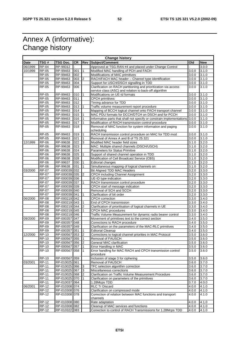
ETSI
ETSI TS 125 321 V5.2.0 (2002-09) 523GPP TS 25.321 version 5.2.0 Release 5
Annex A (informative): Change history
Change history Date TSG # TSG Doc. CR Rev Subject/Comment Old New 06/1999 RP-04 RP-99312 - Approved at TSG-RAN #4 and placed under Change Control - 3.0.0 10/1999 RP-05 RP-99463 001 1 Modified MAC handling of PCH and FACH 3.0.0 3.1.0 RP-05 RP-99463 002 Modifications of MAC primitives 3.0.0 3.1.0 RP-05 RP-99463 003 2 RACH/FACH MAC header – Channel type identification 3.0.0 3.1.0 RP-05 RP-99463 004 Support for USCH/DSCH signalling in TDD 3.0.0 3.1.0 RP-05 RP-99463 006 Clarification on RACH partitioning and prioritization via access
service class (ASC) and relation to back-off algorithm 3.0.0 3.1.0
RP-05 RP-99463 010 1 Modifications on UE-Id formats 3.0.0 3.1.0 RP-05 RP-99463 011 CPCH primitives 3.0.0 3.1.0 RP-05 RP-99463 012 Timing advance for TDD 3.0.0 3.1.0 RP-05 RP-99463 013 1 Traffic volume measurement report procedure 3.0.0 3.1.0 RP-05 RP-99463 014 Mapping of BCCH logical channel onto FACH transport channel 3.0.0 3.1.0 RP-05 RP-99463 015 1 MAC PDU formats for DCCH/DTCH on DSCH and for PCCH 3.0.0 3.1.0 RP-05 RP-99463 016 1 Informative parts that shall not specify or constrain implementations 3.0.0 3.1.0 RP-05 RP-99463 017 1 Modification of RACH transmission control procedure 3.0.0 3.1.0 RP-05 RP-99463 018 Removal of MAC function for system information and paging
scheduling 3.0.0 3.1.0
RP-05 RP-99463 019 1 RACH transmission control procedure on MAC for TDD mod 3.0.0 3.1.0 RP-05 RP-99463 021 1 Removal of Annex A and B of TS 25.321 3.0.0 3.1.0 12/1999 RP-06 RP-99638 022 3 Modified MAC header field sizes 3.1.0 3.2.0 RP-06 RP-99638 023 MAC: Multiple shared channels (DSCH/USCH) 3.1.0 3.2.0 RP-06 RP-99638 024 Parameters for Status Primitive 3.1.0 3.2.0 RP-06 RP-99638 025 1 Support of shared channel operation in TDD 3.1.0 3.2.0 RP-06 RP-99638 028 Modification of Cell Broadcast Service (CBS) 3.1.0 3.2.0 RP-06 RP-99637 030 1 Editorial changes 3.1.0 3.2.0 RP-06 RP-99638 031 1 Simultaneous mapping of logical channels on 3.1.0 3.2.0 03/2000 RP-07 RP-000039 032 Bit Aligned TDD MAC Headers 3.2.0 3.3.0 RP-07 RP-000039 035 2 CPCH including Channel Assignment 3.2.0 3.3.0 RP-07 RP-000039 036 UE-ID type indication 3.2.0 3.3.0 RP-07 RP-000039 037 1 RACH transmission control procedure 3.2.0 3.3.0 RP-07 RP-000039 039 CPCH start of message indication 3.2.0 3.3.0 RP-07 RP-000039 040 Removal of SCH and SCCH 3.2.0 3.3.0 RP-07 RP-000039 041 1 Clarification of bit order 3.2.0 3.3.0 06/2000 RP-08 RP-000219 042 CPCH correction 3.3.0 3.4.0 RP-08 RP-000219 043 1 End of CPCH transmission 3.3.0 3.4.0 RP-08 RP-000219 044 2 Clarification of prioritisation of logical channels in UE 3.3.0 3.4.0 RP-08 RP-000219 045 1 CPCH MAC procedures 3.3.0 3.4.0 RP-08 RP-000219 046 Traffic Volume Measurement for dynamic radio bearer control 3.3.0 3.4.0 09/2000 RP-09 RP-000357 047 Movement of primitives text to the correct section 3.4.0 3.5.0 RP-09 RP-000357 048 Corrections to RACH procedure 3.4.0 3.5.0 RP-09 RP-000357 049 Clarification on the parameters of the MAC-RLC primitives 3.4.0 3.5.0 RP-09 RP-000357 051 1 Editorial Cleanup 3.4.0 3.5.0 12/2000 RP-10 RP-000567 053 2 Corrections to logical channel priorities in MAC Protocol 3.5.0 3.6.0 RP-10 RP-000567 055 1 Removal of FAUSCH 3.5.0 3.6.0 RP-10 RP-000567 056 2 General MAC clarification 3.5.0 3.6.0 RP-10 RP-000567 057 1 Error Handling in MAC 3.5.0 3.6.0 RP-10 RP-000567 058 1 Error handling for MAC RACH and CPCH transmission control
procedure 3.5.0 3.6.0
RP-10 RP-000567 059 Inclusion of stage 3 for ciphering 3.5.0 3.6.0 03/2001 RP-11 RP-010025 061 Removal of FAUSCH 3.6.0 3.7.0 RP-11 RP-010025 066 3 TFC selection algorithm correction 3.6.0 3.7.0 RP-11 RP-010025 067 3 Miscellaneous corrections 3.6.0 3.7.0 RP-11 RP-010025 068 2 Clarification on Traffic Volume Measurement Procedure 3.6.0 3.7.0 RP-11 RP-010025 070 1 Clarification on parameters of the primitives 3.6.0 3.7.0 RP-11 RP-010037 064 1.28Mcps TDD 3.7.0 4.0.0 06/2001 RP-12 RP-010308 074 RLC Tr Discard 4.0.0 4.1.0 RP-12 RP-010308 076 Clarification on compressed mode 4.0.0 4.1.0 RP-12 RP-010308 078 Correction of relation between MAC functions and transport
channels 4.0.0 4.1.0
RP-12 RP-010308 080 Rate adaptation 4.0.0 4.1.0 RP-12 RP-010308 082 Cleanup of MAC services and functions 4.0.0 4.1.0 RP-12 RP-010322 083 Correction to control of RACH Transmissions for 1.28Mcps TDD 4.0.0 4.1.0
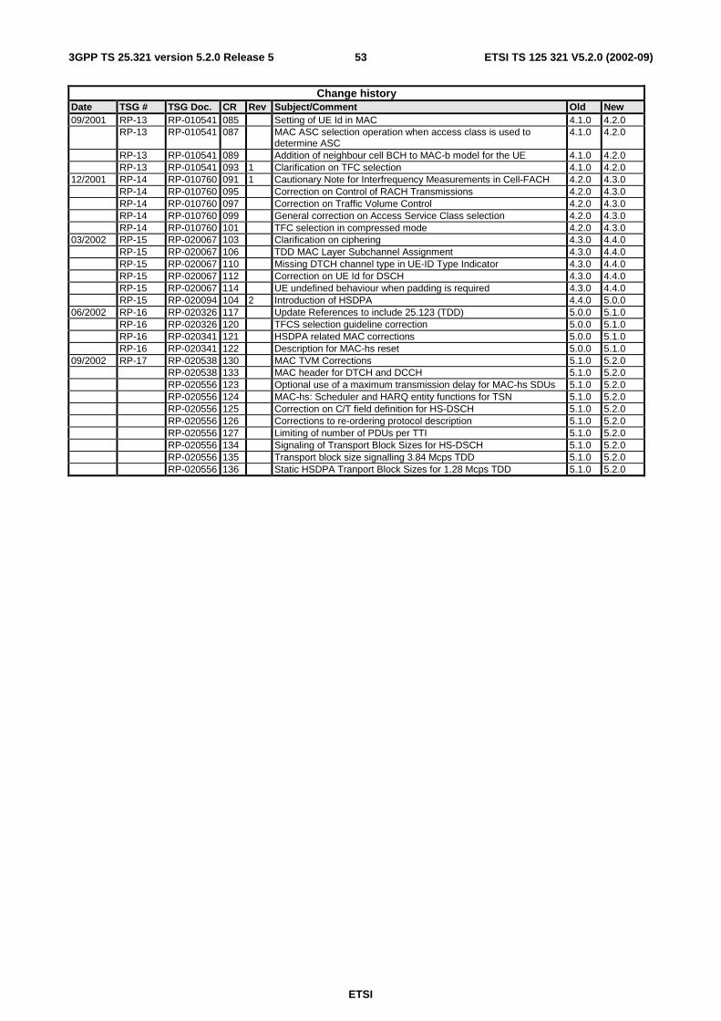
ETSI
ETSI TS 125 321 V5.2.0 (2002-09) 533GPP TS 25.321 version 5.2.0 Release 5
Change history Date TSG # TSG Doc. CR Rev Subject/Comment Old New 09/2001 RP-13 RP-010541 085 Setting of UE Id in MAC 4.1.0 4.2.0 RP-13 RP-010541 087 MAC ASC selection operation when access class is used to
determine ASC 4.1.0 4.2.0
RP-13 RP-010541 089 Addition of neighbour cell BCH to MAC-b model for the UE 4.1.0 4.2.0 RP-13 RP-010541 093 1 Clarification on TFC selection 4.1.0 4.2.0 12/2001 RP-14 RP-010760 091 1 Cautionary Note for Interfrequency Measurements in Cell-FACH 4.2.0 4.3.0 RP-14 RP-010760 095 Correction on Control of RACH Transmissions 4.2.0 4.3.0 RP-14 RP-010760 097 Correction on Traffic Volume Control 4.2.0 4.3.0 RP-14 RP-010760 099 General correction on Access Service Class selection 4.2.0 4.3.0 RP-14 RP-010760 101 TFC selection in compressed mode 4.2.0 4.3.0 03/2002 RP-15 RP-020067 103 Clarification on ciphering 4.3.0 4.4.0 RP-15 RP-020067 106 TDD MAC Layer Subchannel Assignment 4.3.0 4.4.0 RP-15 RP-020067 110 Missing DTCH channel type in UE-ID Type Indicator 4.3.0 4.4.0 RP-15 RP-020067 112 Correction on UE Id for DSCH 4.3.0 4.4.0 RP-15 RP-020067 114 UE undefined behaviour when padding is required 4.3.0 4.4.0 RP-15 RP-020094 104 2 Introduction of HSDPA 4.4.0 5.0.0 06/2002 RP-16 RP-020326 117 Update References to include 25.123 (TDD) 5.0.0 5.1.0 RP-16 RP-020326 120 TFCS selection guideline correction 5.0.0 5.1.0 RP-16 RP-020341 121 HSDPA related MAC corrections 5.0.0 5.1.0 RP-16 RP-020341 122 Description for MAC-hs reset 5.0.0 5.1.0 09/2002 RP-17 RP-020538 130 MAC TVM Corrections 5.1.0 5.2.0 RP-020538 133 MAC header for DTCH and DCCH 5.1.0 5.2.0 RP-020556 123 Optional use of a maximum transmission delay for MAC-hs SDUs 5.1.0 5.2.0 RP-020556 124 MAC-hs: Scheduler and HARQ entity functions for TSN 5.1.0 5.2.0 RP-020556 125 Correction on C/T field definition for HS-DSCH 5.1.0 5.2.0 RP-020556 126 Corrections to re-ordering protocol description 5.1.0 5.2.0 RP-020556 127 Limiting of number of PDUs per TTI 5.1.0 5.2.0 RP-020556 134 Signaling of Transport Block Sizes for HS-DSCH 5.1.0 5.2.0 RP-020556 135 Transport block size signalling 3.84 Mcps TDD 5.1.0 5.2.0 RP-020556 136 Static HSDPA Tranport Block Sizes for 1.28 Mcps TDD 5.1.0 5.2.0
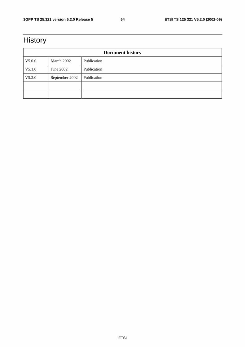
ETSI
ETSI TS 125 321 V5.2.0 (2002-09) 543GPP TS 25.321 version 5.2.0 Release 5
History
Document history
V5.0.0 March 2002 Publication
V5.1.0 June 2002 Publication
V5.2.0 September 2002 Publication