Embed Size (px)
Citation preview
NLH 2013 Amended General Rate ApplicationUndertaking -Fi1edg)t9 lipaoLi Board Secretary:
--^._
Undertaking 82
Page 199, line 11 to Page 201, line 14
Re: Information 1132
Re: Response to IC-NLH-26, attachment one, in the 2011 Capital Budget Application
Undertake to provide the level one condition assessment (by AMEC) that was referenced inattachment 1 of IC-NLH-26.
The level 1 condition assessment completed by AMEC for the Holyrood Thermal GenerationStation (HGTS) dated January 28, 2011 was filed under Exhibit 444 of the Muskrat Falls Review.
Pages 11-121 to 11-137 of this report relate to the findings regarding the level 1 assessment ofthe Gas Turbine at the HTGS. This is attached as Undertaking 82 Attachment 1.
Newfoundland and Labrador Hydro a NALCOR Energy Co. Holyrood Thermal Generating Station Condition Assessment & Life Extension Study
28 Jan 2011 P164200 Rev 0 Page 11-121
11.2.4 Asset 7133 – Marine Terminal
The marine terminal and facilities was excluded from the assessment at the kick-off meeting and are being looked at by others.
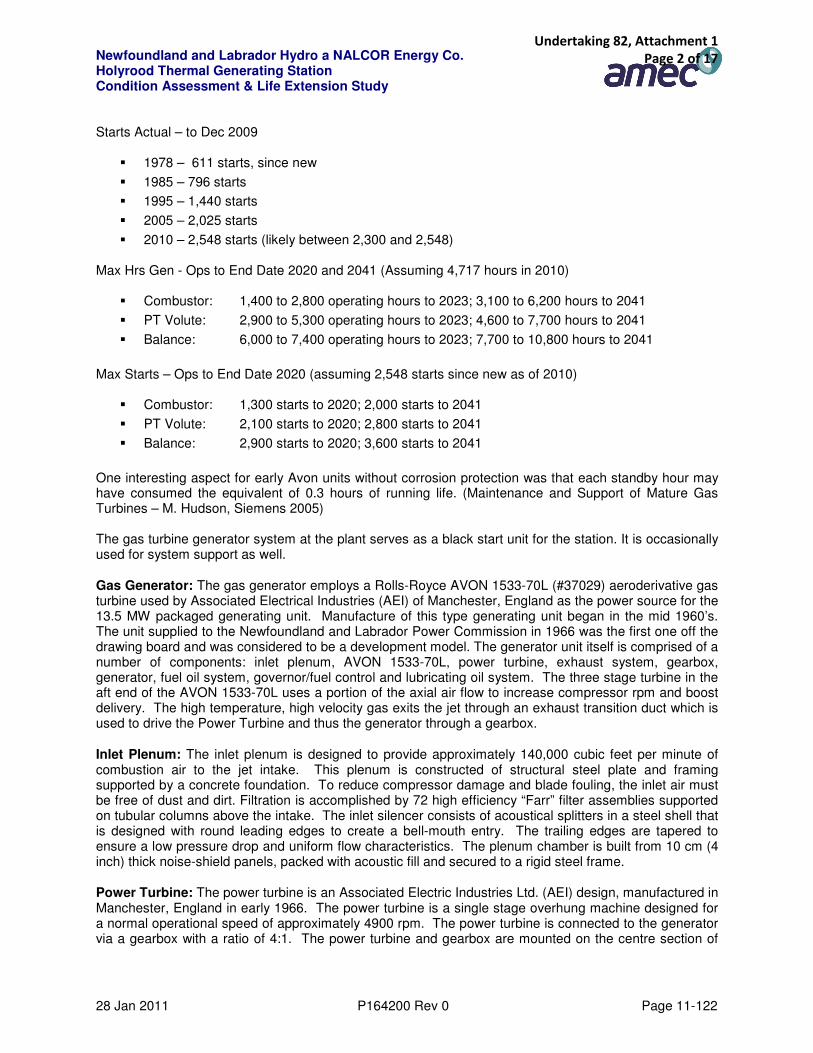
11.2.5 Asset 7202 – Gas Turbine Genset
(Detailed Technical Assessment in Working Papers, Appendix 13)
Unit #: GAS TURBINE
Asset Class # BU 1273 Gas Turbine
SCI & System: 7202 Gas Turbine System
Sub-Systems:
7058 GT Power Turb & G/B
7308 GT Avon Jet Engine
7309 GT Gen
7310 HRD GT E&C
7311 GT Aux Systems
11.2.5.1 Description
Original Manufactured/Delivered 1969 In-Service Date at Holyrood 1986 End of Planned Life Date 2041 Last Combustion System Inspection/Overhaul 2009 Next Major Overhaul/Inspection 2011 (Recommended) Next Major Overhaul/Inspection (Planned) 2011 (On Hold) Planned air intake Upgrade 2011 (On Hold) Planned new exhaust stack 2011 (On Hold) Planned air radiator replacement 2012 (On Hold) Planned air intake & building upgrade 2014 (On Hold) Planned Upgrades 2015/16 (On Hold) The hours associated with the unit are: Hours Actual - Ops to Dec 2009
� 1978 – 1,749 operating hrs since new (+85,000 idle hours)
� 1985 – 2,139 operating hrs since new (+170,000 idle hours)
� 1995 – 3,475 operating hrs since new (+256,000 idle hours)
� 2005 – 3,807 operating hrs since new (+343,000 idle hours)
� 2010 – 4,717 operating hrs since new (+386,000 idle hours)
Undertaking 82, Attachment 1 Page 1 of 17
Newfoundland and Labrador Hydro a NALCOR Energy Co. Holyrood Thermal Generating Station Condition Assessment & Life Extension Study
28 Jan 2011 P164200 Rev 0 Page 11-122
Starts Actual – to Dec 2009
� 1978 – 611 starts, since new
� 1985 – 796 starts
� 1995 – 1,440 starts
� 2005 – 2,025 starts
� 2010 – 2,548 starts (likely between 2,300 and 2,548) Max Hrs Gen - Ops to End Date 2020 and 2041 (Assuming 4,717 hours in 2010)
� Combustor: 1,400 to 2,800 operating hours to 2023; 3,100 to 6,200 hours to 2041
� PT Volute: 2,900 to 5,300 operating hours to 2023; 4,600 to 7,700 hours to 2041
� Balance: 6,000 to 7,400 operating hours to 2023; 7,700 to 10,800 hours to 2041
Max Starts – Ops to End Date 2020 (assuming 2,548 starts since new as of 2010)
� Combustor: 1,300 starts to 2020; 2,000 starts to 2041
� PT Volute: 2,100 starts to 2020; 2,800 starts to 2041
� Balance: 2,900 starts to 2020; 3,600 starts to 2041
One interesting aspect for early Avon units without corrosion protection was that each standby hour may have consumed the equivalent of 0.3 hours of running life. (Maintenance and Support of Mature Gas Turbines – M. Hudson, Siemens 2005) The gas turbine generator system at the plant serves as a black start unit for the station. It is occasionally used for system support as well.
Gas Generator: The gas generator employs a Rolls-Royce AVON 1533-70L (#37029) aeroderivative gas turbine used by Associated Electrical Industries (AEI) of Manchester, England as the power source for the 13.5 MW packaged generating unit. Manufacture of this type generating unit began in the mid 1960’s. The unit supplied to the Newfoundland and Labrador Power Commission in 1966 was the first one off the drawing board and was considered to be a development model. The generator unit itself is comprised of a number of components: inlet plenum, AVON 1533-70L, power turbine, exhaust system, gearbox, generator, fuel oil system, governor/fuel control and lubricating oil system. The three stage turbine in the aft end of the AVON 1533-70L uses a portion of the axial air flow to increase compressor rpm and boost delivery. The high temperature, high velocity gas exits the jet through an exhaust transition duct which is used to drive the Power Turbine and thus the generator through a gearbox.
Inlet Plenum: The inlet plenum is designed to provide approximately 140,000 cubic feet per minute of combustion air to the jet intake. This plenum is constructed of structural steel plate and framing supported by a concrete foundation. To reduce compressor damage and blade fouling, the inlet air must be free of dust and dirt. Filtration is accomplished by 72 high efficiency “Farr” filter assemblies supported on tubular columns above the intake. The inlet silencer consists of acoustical splitters in a steel shell that is designed with round leading edges to create a bell-mouth entry. The trailing edges are tapered to ensure a low pressure drop and uniform flow characteristics. The plenum chamber is built from 10 cm (4 inch) thick noise-shield panels, packed with acoustic fill and secured to a rigid steel frame.
Power Turbine: The power turbine is an Associated Electric Industries Ltd. (AEI) design, manufactured in Manchester, England in early 1966. The power turbine is a single stage overhung machine designed for a normal operational speed of approximately 4900 rpm. The power turbine is connected to the generator via a gearbox with a ratio of 4:1. The power turbine and gearbox are mounted on the centre section of
Undertaking 82, Attachment 1 Page 2 of 17

Newfoundland and Labrador Hydro a NALCOR Energy Co. Holyrood Thermal Generating Station Condition Assessment & Life Extension Study
28 Jan 2011 P164200 Rev 0 Page 11-123
the unit bedplate with this section also forming the main lubricating oil tank. Auxiliary and emergency oil pumps are mounted on this same base plate.
The power turbine casings (Volute) were replaced in 1986 as part of the major upgrade.
Exhaust System: The exhaust casing (volute) is a welded fabrication divided along the horizontal centreline. It turns the gasses transversely to the machine and vertically upwards to the exhaust silencer.
The exhaust stack is constructed of heavy gauge steel plate with light gauge steel cladding on the exterior. The exterior cladding of the lower half of the exhaust stack is constructed of heavy gauge steel plate. This stack was replaced during the 1986 major upgrade. The snow doors on the exhaust stacks are pneumatically actuated and were a new addition in 1986 to reduce corrosion of the volute and power turbine from infiltration of snow and rain water which promoted corrosion within the unit. New limit switches installed on the doors in 2009 indicate the position (opened or closed) of each door at the control station.
Gear Box: The main gearbox was manufactured by AEI in Manchester, England. It is designed to provide an approximate 4:1 speed ratio from the power turbine shaft to the main generator shaft. The gear train is fitted to the power turbine rotor by semi-flexible coupling housed within the gearbox. The gears are of the single helical, single reduction type with the pinion mounted directly above the wheel. A removable top cover allows for inspection without disturbing the alignments.
Generator: The Generator is an air-cooled, 14MW, 13.8 kV, 3 phase, Type AG 80/100, built by Associated Electric Industries (AEI) of Rugby, England in 1966. It has a rotating-field, salient-pole tube with 6 poles and rotates at 1200 rpm. The brushless exciter eliminates the danger of contamination by carbon dust and minimizes maintenance. Semi-conductor rectifiers rotating within the generator / exciter shaft provide excitation for the main generator field.
The generator is a critical component in the availability and reliability of the gas turbine, in that its loss would mean the total loss of the GT generation as well as black start capability for the Holyrood operation.
Fuel Oil System: The plant’s gas turbine uses No. 2 diesel fuel which is delivered to site by truck. The off-loading pump is located outdoors at the northwest corner of the gas turbine building and has above-ground piping stretching to the bulk storage tanks. The two fuel tanks were fabricated in 1998 to ULC-S601-93 standards, with an above ground doubled wall and have a total storage capacity of 200,000 litres.
The offloading system is comprised of a single 600 volt pump arrangement with local start / stop control. Power for the motor is supplied from the gas turbine MCC control centre. The piping installation is typical with a 3 inch Y strainer, isolation valves and piping to the storage tanks.
Two 100%, 600 volt, centrifugal forwarding pumps provide low pressure No. 2 diesel fuel for the jet engine. The fuel passes through a duplex suction strainer and a 5 micron discharge filter before reaching the jet engine. The fuel line also incorporates a fuel flow / totalizing meter and a fire system trip valve prior to entering the building.
Governor and Fuel Control: The standard Avon fuel control system is used without alteration as a basis for the AP1 governing and fuel control system. The throttle valve is used as a generator valve and the H.P. cock as a fuel shut-off valve for normal and emergency shut-downs. The governing system is of the sensitive oil type in which fluid pressure is used to transmit the movement of the governor pilot valve to the operating mechanism of the governor valve, in this case the Avon throttle.
Undertaking 82, Attachment 1 Page 3 of 17

Newfoundland and Labrador Hydro a NALCOR Energy Co. Holyrood Thermal Generating Station Condition Assessment & Life Extension Study
28 Jan 2011 P164200 Rev 0 Page 11-124
The governor is manufactured by Woodward and is driven via gearing from the end of the high speed pinion shaft. The governor is a fly-weight type and carries its own oil supply.
Woodward Governor suggests that the present system has a reliability of about 50%. In addition spare parts for this system are not carried and would have to be fabricated requiring long delivery times.
Control Room & MCC/ Switchgear Room: Within the gas turbine building, the electrical and control systems consist of a rotating brushless exciter, an automatic voltage regulator (AVR), a start rectifier, PLC control modules, motor control centre (MCC), electronic governors, synchronizer, and protection and monitoring equipment. The brushless exciter, AVR and start rectifier were manufactured by AEI Limited of Manchester, England in the mid-1960s. The programmable logic controller (PLC), governor, synchronizer and monitoring equipment were newly installed in 1986. The exciter and AVR unit act in combination to supply a controlled DC current to the wound rotor of the main generator which in turn controls its stator terminal voltage (13.8 kV) and Mvar delivery. The start rectifier converts station AC current into the high DC current necessary to rotate the Jet engine to ignition. The governor consists of two Woodward units: one that controls the jet acceleration on start-up and the second that controls the power turbine/generator during synchronization and Mwatt loading. In 1986, the current Gem 80/500 PLC replaced all relay logic and is now the primary controlling medium for the gas turbine. A current assessment undertaken by Hydro Engineering Services will determine the feasibility of replacing or upgrading all the AEI electrical equipment for the Holyrood Gas Turbine
Excitation System: The exciter is a rotating brushless type mounted on a stub to the main rotating shaft. It was designed to ANSI Specification C50-13. The AC output from the exciter armature is fed through a set of diodes that are mounted on the rotor and are used to produce a DC voltage. The voltage is fed directly to the field winding of the main generator which is also mounted on the same rotating shaft.
The excitation control system consists of a “Normal” and “Standby” automatic voltage regulator (AVR) backed up by a “Manual” control mode. The AVR controls the strength of the magnetic field in the exciter by varying the amount of current through the stationary exciter field windings.
Switchgear: Primary voltage generated by the GT (Gas Turbine) is 13,300 Volts. The installed gas turbine capacity is 13.5 MW, however based on limiting factors the unit sees normal operation of ~12 MW. Originally this power was fed through a 13.8 kV oil circuit breaker and then through a 13.8 kV fusible switch. The oil circuit breaker is no longer functional but remains installed due to the current transformer (CT’s) in this breaker. These CT’s are essential to the protection of the generator and the 13.8 kV/4.160 14 MVA transformer. Power is then fed from the transformer at 4.160 kV to breaker SSB-2 in station panelboard SB12. Power from the CT or station power also feeds a 13.8 kV fused disconnect switch through a 75 kVA 13.8 kV/575 V transformer that provides power back to the station system.
Fire Protection System: The fire system is an Ansul Inergen total-flooding type that can operate automatically via fire detection or manually via pull stations. The system is comprised of Inergen storage containers, piping, nozzles, control panel, actuators, detection and alarm devices, and pressure relief dampers. It was installed in 2000 to replace the Halon fire system in respect of the ozone depleting substance regulations.
Undertaking 82, Attachment 1 Page 4 of 17

Newfoundland and Labrador Hydro a NALCOR Energy Co. Holyrood Thermal Generating Station Condition Assessment & Life Extension Study
28 Jan 2011 P164200 Rev 0 Page 11-125
FIGURE 11-34 GTG BUILDING & LIGHT OIL STORAGE
FIGURE 11-35 LIGHT OIL RECEIVING & LUBE OIL
RADIATOR
Undertaking 82, Attachment 1 Page 5 of 17

Newfoundland and Labrador Hydro a NALCOR Energy Co. Holyrood Thermal Generating Station Condition Assessment & Life Extension Study
28 Jan 2011 P164200 Rev 0 Page 11-126
FIGURE 11-36 GTG GAS ENGINE & GENERATOR
Compressed Air System: The compressed air system consists of a single 600 volt motor/compressor unit, a 310 L (82 gallon) storage tank, a Pall instrument air dryer and a small control and monitoring panel. The system is designed to supply 700 kPa instrument air to operate the power turbine snow doors, the main generator exhaust and intake louvers and the jet engine intake and exhaust cooling air louvers. It also has provisions for a four-bottle nitrogen back-up supply in the event of a compressor system failure. The control panel provides pressure indication for the system and a transfer valve to the N2 supply.
FIGURE 11-37 GTG LIGHT OIL RECEIVING
Undertaking 82, Attachment 1 Page 6 of 17
Newfoundland and Labrador Hydro a NALCOR Energy Co. Holyrood Thermal Generating Station Condition Assessment & Life Extension Study
28 Jan 2011 P164200 Rev 0 Page 11-127
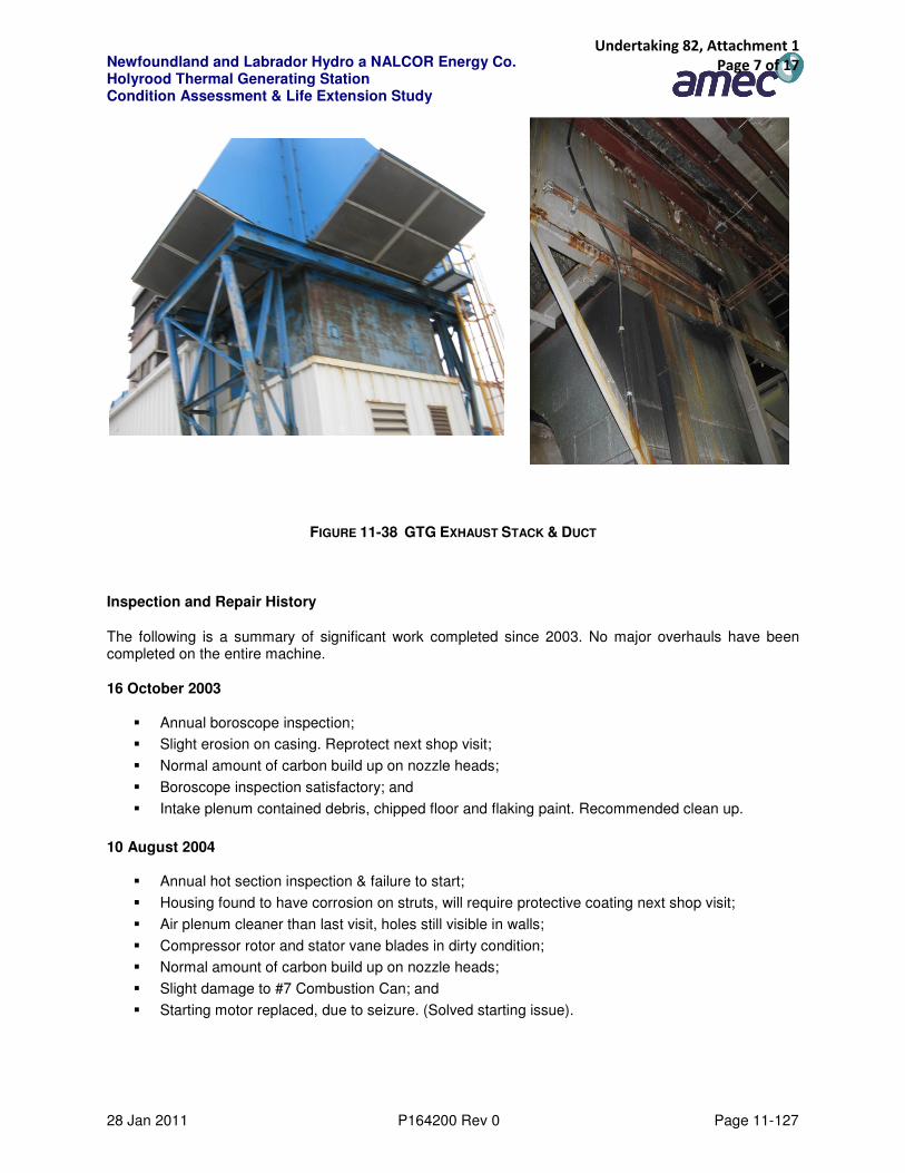
FIGURE 11-38 GTG EXHAUST STACK & DUCT
Inspection and Repair History
The following is a summary of significant work completed since 2003. No major overhauls have been completed on the entire machine.
16 October 2003
� Annual boroscope inspection;
� Slight erosion on casing. Reprotect next shop visit;
� Normal amount of carbon build up on nozzle heads;
� Boroscope inspection satisfactory; and
� Intake plenum contained debris, chipped floor and flaking paint. Recommended clean up.
10 August 2004
� Annual hot section inspection & failure to start;
� Housing found to have corrosion on struts, will require protective coating next shop visit;
� Air plenum cleaner than last visit, holes still visible in walls;
� Compressor rotor and stator vane blades in dirty condition;
� Normal amount of carbon build up on nozzle heads;
� Slight damage to #7 Combustion Can; and
� Starting motor replaced, due to seizure. (Solved starting issue).
Undertaking 82, Attachment 1 Page 7 of 17

Newfoundland and Labrador Hydro a NALCOR Energy Co. Holyrood Thermal Generating Station Condition Assessment & Life Extension Study
28 Jan 2011 P164200 Rev 0 Page 11-128
27 September 2005
� Annual inspection and boroscope inspection;
� Front Bearing Housing, outer bushes loose;
� Front Bearing Housing, Corrosion/ pitting;
� Corrosion/ Rust found in Plenum;
� HP NGV’s have slight erosion of the leading edges and minor cracks in the trailing edges;
� Flame tubes have minor erosion on some of the wiggle strips and some carbon build up within the flame tube, especially around the dish where liquid fuel has collected;
� Normal amount of carbon build up on nozzle heads; and
� Hot gas leakage at Exhaust Transition duct to power turbine.
13 March 2006
� Leak in each end of the gearbox at the bearing seals. (Caused fire when oil leaked into insulation around PT and dripped onto top of tank). Greenray discovered turbine shaft/seal modifications, recommended machining and reconditioning.
13 April 2006
� Fuel oil leak on underside of gas turbine at IGV Ram, seal deterioration.
25 May 2007
� AVON repair and boroscope inspection: IGV ram leak, ignitor failure, hot air leak from #6 burner, bellmouth nuts loose, combustion casing boroscope port bolts loose, bleed valve ducting broken and separated, fuel lag at idle and struggling at speed;
� Significant sparking coming from PT splash plate (rubbing shaft). Suggests bearings are worn and thus damaged seal;
� 2 IGV bushes replaced due to wear in the bush. (Majority of bushes and retaining nuts were replaced as well as the locking bush);
� Rebuild of the intake with securing bolts torque and locked;
� IGV ram replaced due to leak;
� Fuel filter replaced due to feed issues;
� Bolts holding PT seal were not tight, seal incorrectly installed;
� Ignitor, lead and box were replaced;
� High fuel consumption noticed at fuel drain valve, suspect worn seals on FCU and fuel pumps;
� Additional breather recommended for rear of gearbox unit, to reduce leaks;
� Compressor section; front bearing housing, inlet guide vanes have significant corrosion and coating loss;
� Combustion cans show signs of cracking, material loss (could lead to further turbine damage);
� IP nozzle guide vanes and HP nozzle guide vanes show signs of cracking on trailing edges;
� Change PT lube oil filters; and
� Replace/ Repair exhaust snow doors.
Undertaking 82, Attachment 1 Page 8 of 17
Newfoundland and Labrador Hydro a NALCOR Energy Co. Holyrood Thermal Generating Station Condition Assessment & Life Extension Study
28 Jan 2011 P164200 Rev 0 Page 11-129
21 May 2008
� Package filtration inspection;
� Plenum survey;
� Windmill inspection of compressor;
� Boroscope of compressor and VIGV;
� Fuel/oil system: connection, fuel pump/ oil pump, pipelines, oil level & quality, filter and basket removal (replacement consumables);
� On engine review: bleed valves, IGV ram (filter review), gearbox inspection (filters, speed pick up, consumable change), fuel control unit review, oil cooler, fuel filter change, burner removal (ultrasonic cleaning), fuel rail inspection, drain valve operation, thermocouple inspection (terminal cleaning), transition inspection, removal of insulation, rectify leaks, inspect LP blades;
� Boroscope inspection: rear of compressor, snout area, combustion can, HP nozzle guide vanes, cooper beams (crooks washers), turbine section;
� PT and gearbox review; and
� Controls review.
10 June 2008
� Water pooling noted in intake plenum along with holes in structure and loose debris;
� Compressor showing significant corrosion and pitting on front bearing housing, inlet guide vanes and compressor stages, physical signs of salt evident;
� Combustion cans need to be replaced due to extensive corrosion, #1 and #2 burners removed for inspection. Seized bolts prevented removal of others;
� Hard impact damage evident in turbine stages, suspect debris from combustion cans and/or intake plenum;
� Suggested unit overhaul for blade recoating etc.; and
� Fuel pump and FCU to be repaired.
15 October 2009
� Engine removed and placed on site, in vertical stand for repairs (combustion cans);
� Combustion cans were replaced and FCU and fuel pump repaired;
� Loose discharge nozzles, due to broken brackets (2 off) to be replaced in future;
� PT inspection showed signs of light blade rub, none on stators. Diaphragm free of damage;
� PT inlet cone cranks, to be repaired;
� Thermocouple damage, quick fixed. To be upgraded;
� Exhaust stack needs replacement, lower components noted in good condition. Door opening components to be serviced; and
� Transition duct piston rings seals to be replaced.
20 November 2009
� Commissioning;
� Fuel control solenoid valve burnt out and replaced;
� Multiple start trips due to; low fuel pressure, low oil pressure, incomplete start sequence; determined igniter box malfunction, N2 probe incorrectly connected & FCU actuator tuning;
Undertaking 82, Attachment 1 Page 9 of 17

Newfoundland and Labrador Hydro a NALCOR Energy Co. Holyrood Thermal Generating Station Condition Assessment & Life Extension Study
28 Jan 2011 P164200 Rev 0 Page 11-130
� Exhaust transition lagging replaced due to fuel saturation;
� Split air manifold cracks, to be repaired; and
� Suggest monitoring setup for the 8 EGT thermocouples.
Undertaking 82, Attachment 1 Page 10 of 17

Newfoundland and Labrador Hydro a NALCOR Energy Co. Holyrood Thermal Generating Station Condition Assessment & Life Extension Study
28 Jan 2011 P164200 Rev 0 Page 11-131
11.2.5.2 Condition Assessment
Essentially the unit is in very poor condition and overdue for a major overhaul of most components. The condition assessment of the gas turbine gensets is as follows in Table 11-46.
TABLE 11-46 CONDITION ASSESSMENT – GAS TURBINE GENSETS
Notes: 1. A “(bracketed)” value in the “Current Expected Remaining Life” column is a highly probable minimum value that is considered subject to some subsequent verification during further investigation, including at the next test or overhaul. It may be addressed as part of a Level 2 test. A value identified as “(X/Y)” has been included for the steam turbine and generator where the recommended minimum value is the lower of the two, but that the higher may be achievable at a higher level of failure risk and/or unreliability.
2. The “Next Regular Inspection” column identifies a regular inspection (not necessarily an overhaul or detailed Level 2 test) that is currently planned and known to AMEC and which may provide further insight into the equipment life. The “Next Planned Overhaul or Major Inspection” column is intended to identify known detailed inspections and/or overhauls that will definitively update current remaining life assumptions and which are a “Desired Life” stage for condition assessment purposes. Note that where a detailed inspection/overhaul date is highlighted in yellow then it is a specific AMEC recommendation and that date is the basis for conclusions on the ability to make the next detailed inspection/overhaul. Where no specific dates have been identified for “Next Regular Inspection” or “Next Planned Overhaul/Major Inspection”, they are left blank.
BU #
1
Asset #
2
Asset #
3
Asset #
4Asset Level 2 Asset Level 3 Description Detail
Cond. Summ.
ID#
Append
#Condition
Status
Identifier
Original Life
(Base Load)
Ops Hrs
(Yrs)
Current Expected
Minimum
Remaining Life
Years
(Subject to Test)
End of Life
(EOL)
Required
Next Regular
Inspection
Next Planned
Overhaul/
Major
Inspection
Capability to
Reach Next
Overhaul
Capability to
Reach EOL
In
Service
1273 7202 0 0 GAS TURBINE SYSTEM GAS TURBINE SYSTEM GAS TURBINE SYSTEM 1 1344 years old and has accumulated about 4,717 hours with 1,548 starts. Four significant overhauls/repairs in 1978, 1986, and
1991 and a combustor replacement in 20074/10 150,000 (30) 1 2020 2010 2011 No No 1969
1273 7202 7058 0 GAS TURBINE SYSTEM GAS TURBINE POWER TURB & G/B GAS TURBINE POWER TURB & G/BPower
Turbine2 13 Overdue for overhaul; corrosion/cracking from moisture leakage. 4/10 150,000 (30) 2 2020 2010 2011 No No 1969
1273 7202 7058 0 GAS TURBINE SYSTEM GAS TURBINE POWER TURB & G/B GAS TURBINE POWER TURB & G/B Gearbox 3 13 Overdue for overhaul; corrosion/cracking from moisture leakage. 4/10 150,000 (30) 2 2020 2010 2011 No No 1969
1273 7202 7308 0 GAS TURBINE SYSTEM GAS TURBINE AVON JET ENGINE GAS TURBINE AVON JET ENGINE 4 13 Overdue for overhaul; corrosion/cracking from seaside moisture and starts. 4/10 150,000 (30) 2 2020 2010 2011 No No 1969
1273 7202 7309 0 GAS TURBINE SYSTEM GAS TURBINE GENERATOR GAS TURBINE GENERATOR 5 13 Overdue for testing of rotor/stator/auxiliaries. 4/10 200000 (40) 5 2020 2010 2011 Yes No 1969
1273 7202 7310 0 GAS TURBINE SYSTEM GAS TURBINE ELECT & CONTROL GAS TURBINE ELECT & CONTROL 6 13 Relatively new. 4/10 (15) 12 2020 2010 2011 Yes Yes 1986
1273 7202 7310 333927 GAS TURBINE SYSTEM GAS TURBINE ELECT & CONTROL GAS TURBINE DCS CONTROL 7 13 Relatively new. 4/10 (15) 12 2020 2010 2011 Yes Yes 1986
1273 7202 7311 0 GAS TURBINE SYSTEM GAS TURBINE AUXILIARY SYSTEMS GAS TURBINE AUXILIARY SYSTEMS Fire System 8 13 Fire system upgraded to Inergen system in 2000. 4/10 (30) 20 2020 2010 N/A Yes Yes 2000
1273 7202 7311 0 GAS TURBINE SYSTEM GAS TURBINE AUXILIARY SYSTEMS GAS TURBINE AUXILIARY SYSTEMS Exhaust Stack 9 13 Corroded, leaking, Requires replacement. 4/10 (20) 1 2020 2010 2011 No No 1986
1273 7202 7311 0 GAS TURBINE SYSTEM GAS TURBINE AUXILIARY SYSTEMS GAS TURBINE AUXILIARY SYSTEMS Radiator 10 13 Corroded. 4 (20) 3 2020 2010 2011 Yes No 1986
1273 7202 7311 0 GAS TURBINE SYSTEM GAS TURBINE AUXILIARY SYSTEMS GAS TURBINE AUXILIARY SYSTEMS Fuel delivery 11 13 Corroded, external pitting. 4 (30) 3 2020 2010 2011 Yes No 1986
1273 7202 7311 0 GAS TURBINE SYSTEM GAS TURBINE AUXILIARY SYSTEMS GAS TURBINE AUXILIARY SYSTEMS Lube Oil 12 13 Overdue for overhaul. 4 (30) 10 2020 2010 2011 Yes No 1986
1273 7202 7311 99003602 GAS TURBINE SYSTEM GAS TURBINE AUXILIARY SYSTEMS AIR INLET PLENUM CHAMBER Filter Material 13 13 Inlet housing and filtration system replaced in 1986. Water leaking; inappropriate material for environment. 4/10 (30) 2 2020 2010 2011 Yes No 1986
Undertaking 82, Attachment 1 Page 11 of 17

Newfoundland and Labrador Hydro a NALCOR Energy Co. Holyrood Thermal Generating Station Condition Assessment & Life Extension Study
28 Jan 2011 P164200 Rev 0 Page 11-132
11.2.5.3 Actions
Based on the condition assessment, the following actions are recommended for the gas turbine genset.
TABLE 11-47 RECOMMENDED ACTIONS – GAS TURBINE GENSET
BU #
1
Asset #
2
Asset #
3
Asset #
4Asset 2/3 Asset 3/4 Description Action # App # Action Year Priority
1273 7202 0 0 GAS TURBINE SYSTEM GAS TURBINE SYSTEM GAS TURBINE SYSTEM 1 13
1273 7202 7058 0 GAS TURBINE SYSTEM GAS TURBINE POWER TURB & G/B GAS TURBINE POWER TURB & GEARBOX 2 13 Level 2 assessment in 2010 and/or overhaul in 2011/12. 2010 1
1273 7202 7308 0 GAS TURBINE SYSTEM GAS TURBINE AVON JET ENGINE GAS TURBINE AVON JET ENGINE 3 13 Level 2 assessment in 2010 and/or overhaul in 2011/13. 2010 1
1273 7202 7309 0 GAS TURBINE SYSTEM GAS TURBINE GENERATOR GAS TURBINE GENERATOR 4 13 Level 2 assessment in 2010 and/or overhaul in 2011/14. 2010 1
1273 7202 7310 0 GAS TURBINE SYSTEM GAS TURBINE ELECT & CONTROL GAS TURBINE ELECT & CONTROL 5 6,13 Test in 2014 (6 Year cycle) 2014 2
1273 7202 7310 333927 GAS TURBINE SYSTEM GAS TURBINE ELECT & CONTROL GAS TURBINE DCS CONTROL 6 6,13 No action recommended.
1273 7202 7311 0 GAS TURBINE SYSTEM GAS TURBINE AUXILIARY SYSTEMS GAS TURBINE AUXILIARY SYSTEMS 7 13 No action recommended.
1273 7202 7311 0 GAS TURBINE SYSTEM GAS TURBINE AUXILIARY SYSTEMS GAS TURBINE AUXILIARY SYSTEMS - STACK 8 13,17 Conduct Level 2 inspections of the exhaust stack in 2010. 2010 1
1273 7202 7311 0 GAS TURBINE SYSTEM GAS TURBINE AUXILIARY SYSTEMS GAS TURBINE AUXILIARY SYSTEMS - STACK 9 13,17 Replace the gas turbine stack and affected roof areas asap. 2011 1
1273 7202 7311 0 GAS TURBINE SYSTEM GAS TURBINE AUXILIARY SYSTEMS GAS TURBINE AUXILIARY SYSTEMS - INTAKE 10 13,17Replace the intake filter system suitable for seaside environment asap.
Assess intake structure and corrosion.2011 1
1273 7202 7311 0 GAS TURBINE SYSTEM GAS TURBINE AUXILIARY SYSTEMS GAS TURBINE AUXILIARY SYSTEMS - ENCLOSURE 11 13,17 Expand enclosure and include fuel delivery/rad, etc. 2011 2
1273 7202 7311 0 GAS TURBINE SYSTEM GAS TURBINE AUXILIARY SYSTEMS GAS TURBINE AUXILIARY SYSTEMS - Building 12 13,17 Paint structural members as required, roofing and siding painting. 2010 1
1273 7202 7311 99003602 GAS TURBINE SYSTEM GAS TURBINE AUXILIARY SYSTEMS AIR INLET PLENUM CHAMBER 13 13,17 Replace air filter media and repair inlet plenum. 2011 1
Undertaking 82, Attachment 1 Page 12 of 17
Newfoundland and Labrador Hydro a NALCOR Energy Co. Holyrood Thermal Generating Station Condition Assessment & Life Extension Study
28 Jan 2011 P164200 Rev 0 Page 11-133
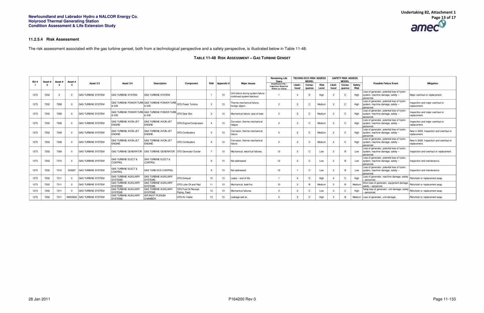
11.2.5.4 Risk Assessment
The risk assessment associated with the gas turbine genset, both from a technological perspective and a safety perspective, is illustrated below in Table 11-48.
TABLE 11-48 RISK ASSESSMENT – GAS TURBINE GENSET
Remaining Life
Years(Insufficient Info -
Inspection Required
Within (x) Years)
Likeli--
hood
Conse-
quence
Risk
Level
Likeli-
hood
Conse-
quence
Safety
Risk
1273 7202 0 0 GAS TURBINE SYSTEM GAS TURBINE SYSTEM GAS TURBINE SYSTEM 1 13Unit failure during system failure -
continued system blackout.1 4 D High 3 C High
Loss of generator, potential loss of hydro
system, machine damage, safety –
personnel.
Major overhaul or replacement.
1273 7202 7058 0 GAS TURBINE SYSTEMGAS TURBINE POWER TURB
& G/B
GAS TURBINE POWER TURB
& G/BGTG Power Turbine 2 13
Thermo-mechanical failure,
foreign object.2 3 C Medium 3 C High
Loss of generator, potential loss of hydro
system, machine damage, safety –
personnel.
Inspection and major overhaul or
replacement.
1273 7202 7058 0 GAS TURBINE SYSTEMGAS TURBINE POWER TURB
& G/B
GAS TURBINE POWER TURB
& G/BGTG Gear Box 3 13 Mechanical failure, seal oil leak. 2 3 C Medium 3 C High
Loss of generator, potential loss of hydro
system, machine damage, safety –
personnel.
Inspection and major overhaul or
replacement.
1273 7202 7308 0 GAS TURBINE SYSTEMGAS TURBINE AVON JET
ENGINE
GAS TURBINE AVON JET
ENGINEGTG Engine/Compressor 4 13
Corrosion, thermo-mechanical
fatigue.2 3 C Medium 3 C High
Loss of generator, potential loss of hydro
system, machine damage, safety –
personnel.
Inspection and major overhaul or
replacement.
1273 7202 7308 0 GAS TURBINE SYSTEMGAS TURBINE AVON JET
ENGINE
GAS TURBINE AVON JET
ENGINEGTG Combustors 5 13
Corrosion, thermo-mechanical
failure.5 2 C Medium 2 C High
Loss of generator, potential loss of hydro
system, machine damage, safety –
personnel.
New in 2009. Inspection and overhaul or
replacement.
1273 7202 7308 0 GAS TURBINE SYSTEMGAS TURBINE AVON JET
ENGINE
GAS TURBINE AVON JET
ENGINEGTG Combustors 6 13
Corrosion, thermo-mechanical
failure.5 2 C Medium 2 C High
Loss of generator, potential loss of hydro
system, machine damage, safety –
personnel.
New in 2009. Inspection and overhaul or
replacement.
1273 7202 7309 0 GAS TURBINE SYSTEM GAS TURBINE GENERATOR GAS TURBINE GENERATOR GTG Generator Exciter 7 13 Mechanical, electrical failures. 12 2 C Low 2 B Low
Loss of generator, potential loss of hydro
system, machine damage, safety –
personnel.
Inspection and overhaul or replacement.
1273 7202 7310 0 GAS TURBINE SYSTEMGAS TURBINE ELECT &
CONTROL
GAS TURBINE ELECT &
CONTROL8 13 Not addressed. 12 2 C Low 2 B Low
Loss of generator, potential loss of hydro
system, machine damage, safety –
personnel.
Inspection and maintenance.
1273 7202 7310 333927 GAS TURBINE SYSTEMGAS TURBINE ELECT &
CONTROLGAS TURB DCS CONTROL 9 13 Not addressed. 12 1 C Low 2 B Low
Loss of generator, potential loss of hydro
system, machine damage, safety –
personnel.
Inspection and maintenance.
1273 7202 7311 0 GAS TURBINE SYSTEMGAS TURBINE AUXILIARY
SYSTEMS
GAS TURBINE AUXILIARY
SYSTEMSGTG Exhaust 10 13 Leaks – end of life. 1 4 D High 4 C High
Loss of generator, machine damage, safety
– personnel.Refurbish or replacement asap.
1273 7202 7311 0 GAS TURBINE SYSTEMGAS TURBINE AUXILIARY
SYSTEMS
GAS TURBINE AUXILIARY
SYSTEMSGTG Lube Oil and Rad 11 13 Mechanical, leak/fire. 10 3 B Medium 3 B Medium
Short loss of generator, equipment damage,
safety – personnel.Refurbish or replacement asap.
1273 7202 7311 0 GAS TURBINE SYSTEMGAS TURBINE AUXILIARY
SYSTEMS
GAS TURBINE AUXILIARY
SYSTEMS
GTG Fuel Oil Receipt,
Piping, Feed12 13 Mechanical failures. 3 2 C Low 3 C High
Temp loss of generator, unit damage, safety
– personnel.Refurbish or replacement asap.
1273 7202 7311 99003602 GAS TURBINE SYSTEMGAS TURBINE AUXILIARY
SYSTEMS
AIR INLET PLENUM
CHAMBERGTG Air Intake 13 13 Leakage salt air. 2 3 C High 3 B Medium Loss of generator, unit damage. Refurbish or replacement asap.
Appendix # Major Issues Possible Failure Event Mitigation
TECHNO-ECO RISK ASSESS
MODEL
SAFETY RISK ASSESS
MODELBU #
1
Asset #
2
Asset #
3
Asset #
4Component RA#Asset 2/3 Asset 3/4 Description
Undertaking 82, Attachment 1 Page 13 of 17
Newfoundland and Labrador Hydro a NALCOR Energy Co. Holyrood Thermal Generating Station Condition Assessment & Life Extension Study
28 Jan 2011 P164200 Rev 0 Page 11-134
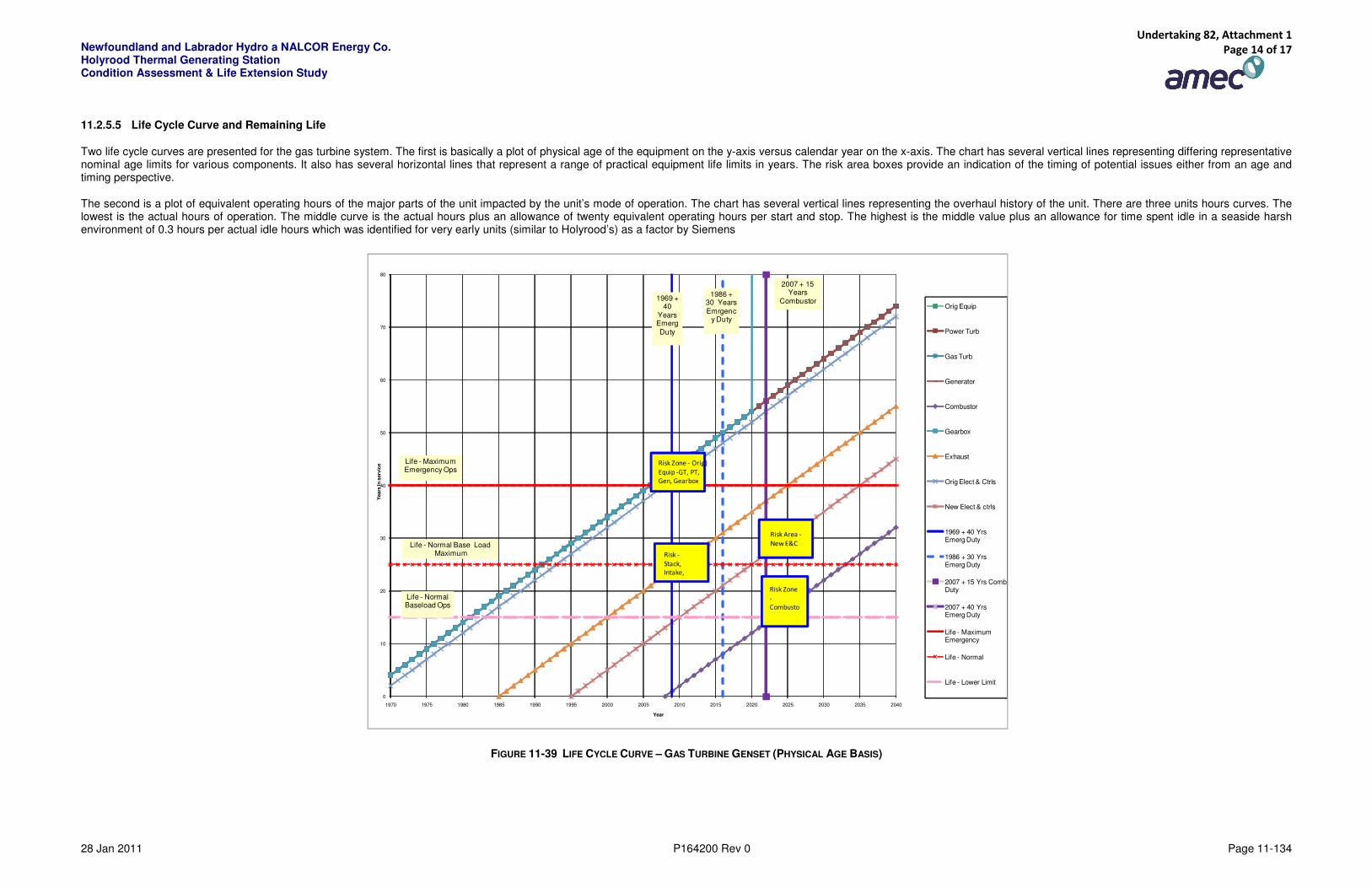
11.2.5.5 Life Cycle Curve and Remaining Life
Two life cycle curves are presented for the gas turbine system. The first is basically a plot of physical age of the equipment on the y-axis versus calendar year on the x-axis. The chart has several vertical lines representing differing representative nominal age limits for various components. It also has several horizontal lines that represent a range of practical equipment life limits in years. The risk area boxes provide an indication of the timing of potential issues either from an age and timing perspective.
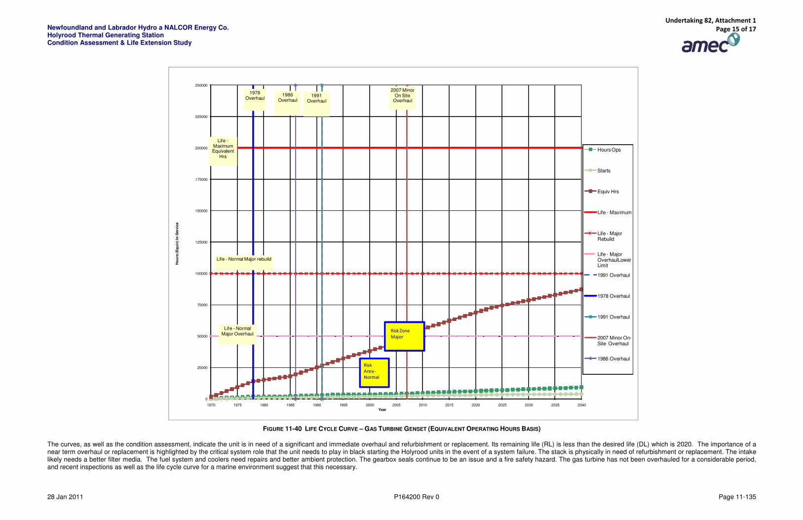
The second is a plot of equivalent operating hours of the major parts of the unit impacted by the unit’s mode of operation. The chart has several vertical lines representing the overhaul history of the unit. There are three units hours curves. The lowest is the actual hours of operation. The middle curve is the actual hours plus an allowance of twenty equivalent operating hours per start and stop. The highest is the middle value plus an allowance for time spent idle in a seaside harsh environment of 0.3 hours per actual idle hours which was identified for very early units (similar to Holyrood’s) as a factor by Siemens
FIGURE 11-39 LIFE CYCLE CURVE – GAS TURBINE GENSET (PHYSICAL AGE BASIS)
0
10
20
30
40
50
60
70
80
1970 1975 1980 1985 1990 1995 2000 2005 2010 2015 2020 2025 2030 2035 2040
Yea
rs In
serv
ice
Year
Orig Equip
Power Turb
Gas Turb
Generator
Combustor
Gearbox
Exhaust
Orig Elect & Ctrls
New Elect & ctrls
1969 + 40 Yrs Emerg Duty
1986 + 30 Yrs Emerg Duty
2007 + 15 Yrs Comb Duty
2007 + 40 Yrs Emerg Duty
Life - Maximum Emergency
Life - Normal
Life - Lower Limit
2007 + 15 Years
Combustor
Life - Normal Baseload Ops
1986 + 30 Years Emrgenc
y Duty
Life - Maximum Emergency Ops
Life - Normal Base LoadMaximum
Risk Zone - Orig)
Equip -GT, PT,
Gen, Gearbox
Risk Zone
-
Combusto
1969 + 40
Years Emerg Duty
Risk -
Stack,
Intake,
Risk Area -
New E&C
Undertaking 82, Attachment 1 Page 14 of 17
Newfoundland and Labrador Hydro a NALCOR Energy Co. Holyrood Thermal Generating Station Condition Assessment & Life Extension Study
28 Jan 2011 P164200 Rev 0 Page 11-135
FIGURE 11-40 LIFE CYCLE CURVE – GAS TURBINE GENSET (EQUIVALENT OPERATING HOURS BASIS)
The curves, as well as the condition assessment, indicate the unit is in need of a significant and immediate overhaul and refurbishment or replacement. Its remaining life (RL) is less than the desired life (DL) which is 2020. The importance of a near term overhaul or replacement is highlighted by the critical system role that the unit needs to play in black starting the Holyrood units in the event of a system failure. The stack is physically in need of refurbishment or replacement. The intake likely needs a better filter media. The fuel system and coolers need repairs and better ambient protection. The gearbox seals continue to be an issue and a fire safety hazard. The gas turbine has not been overhauled for a considerable period, and recent inspections as well as the life cycle curve for a marine environment suggest that this necessary.
0
25000
50000
75000
100000
125000
150000
175000
200000
225000
250000
1970 1975 1980 1985 1990 1995 2000 2005 2010 2015 2020 2025 2030 2035 2040
Ho
urs
(E
qu
iv) In
-Serv
ice
Year
Hours Ops
Starts
Equiv Hrs
Life - Maximum
Life - Major Rebuild
Life - Major OverhaulLower Limit
1991 Overhaul
1978 Overhaul
1991 Overhaul
2007 Minor On-Site Overhaul
1986 Overhaul
2007 Minor On Site
Overhaul
Life - Normal Major Overhaul
1991 Overhaul
Life -Maximum Equivalent
Hrs
Life - Normal Major rebuild
Risk Zone
Major
1978 Overhaul
Risk
Area -
Normal
1986 Overhaul
Undertaking 82, Attachment 1 Page 15 of 17
Newfoundland and Labrador Hydro a NALCOR Energy Co. Holyrood Thermal Generating Station Condition Assessment & Life Extension Study
28 Jan 2011 P164200 Rev 0 Page 11-136
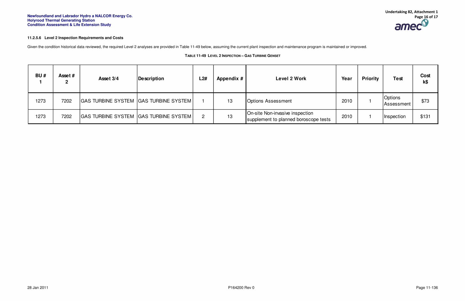
11.2.5.6 Level 2 Inspection Requirements and Costs
Given the condition historical data reviewed, the required Level 2 analyses are provided in Table 11-49 below, assuming the current plant inspection and maintenance program is maintained or improved.
TABLE 11-49 LEVEL 2 INSPECTION – GAS TURBINE GENSET
BU #
1
Asset #
2Asset 3/4 Description L2# Appendix # Level 2 Work Year Priority Test
Cost
k$
1273 7202 GAS TURBINE SYSTEM GAS TURBINE SYSTEM 1 13 Options Assessment 2010 1Options
Assessment$73
1273 7202 GAS TURBINE SYSTEM GAS TURBINE SYSTEM 2 13On-site Non-invasive inspection
supplement to planned boroscope tests2010 1 Inspection $131
Undertaking 82, Attachment 1 Page 16 of 17

Newfoundland and Labrador Hydro a NALCOR Energy Co. Holyrood Thermal Generating Station Condition Assessment & Life Extension Study
28 Jan 2011 P164200 Rev 0 Page 11-137
11.2.5.7 Capital Projects
The suggested typical capital enhancements for the gas turbine gensets include:
TABLE 11-50 SUGGESTED TYPICAL CAPITAL ENHANCEMENTS FOR THE GAS TURBINE GENSETS
BU #
1
Asset #
2
Asset #
3
Asset #
4Asset 2/3 Asset 3/4 Description CAP# Appendix # Capital Item Date Priority
1273 7202 0 0GAS TURBINE
SYSTEM
GAS TURBINE
SYSTEM
GAS TURBINE
SYSTEM1 No capital investment.
1273 7202 7058 0GAS TURBINE
SYSTEM
GAS TURBINE POWER
TURB & G/B
GAS TURBINE POWER
TURB & G/B2 13 Overhaul of power turbine, gearbox. 2011 1
1273 7202 7308 0GAS TURBINE
SYSTEM
GAS TURBINE AVON
JET ENGINE
GAS TURBINE AVON
JET ENGINE3 13 Overhaul gas turbine. 2011 1
1273 7202 7309 0GAS TURBINE
SYSTEM
GAS TURBINE
GENERATOR
GAS TURBINE
GENERATOR4 Refurbish generator. 2015+ 3
1273 7202 7310 0GAS TURBINE
SYSTEM
GAS TURBINE ELECT
& CONTROL
GAS TURBINE ELECT
& CONTROL5 13 Replace electrical equipment for gas turbine. 2010 1
1273 7202 7310 333927GAS TURBINE
SYSTEM
GAS TURBINE ELECT
& CONTROL
GAS TURBINE DCS
CONTROL6 No capital investment.
1273 7202 7311 0GAS TURBINE
SYSTEM
GAS TURBINE
AUXILIARY SYSTEMS
GAS TURBINE
AUXILIARY SYSTEMS7 13 Replace the exhaust stack. 2011 1
1273 7202 7311 0GAS TURBINE
SYSTEM
GAS TURBINE
AUXILIARY SYSTEMS
GAS TURBINE
AUXILIARY SYSTEMS8 13
Upgrade fuel receipt and feeding and radiator -
enclosure.2012 2
1273 7202 7311 99003602GAS TURBINE
SYSTEM
GAS TURBINE
AUXILIARY SYSTEMS
AIR INLET PLENUM
CHAMBER9 13 Replace air inlet plenum/filter media. 2011 2
Undertaking 82, Attachment 1 Page 17 of 17