Embed Size (px)
Citation preview
GB
N
L F
D
Appendix
USER MANUAL INSTALLATION MANUAL
GEBRUIKERSHANDLEIDING INSTALLATIEHANDLEIDING
MANUEL D'UTILISATION
MANUEL D'INSTALLATION
BEDIENUNGSANLEITUNG MONTAGEANLEITUNG
Phoenix Multi Compact 12 / 800 / 35 24 / 800 / 16 12 / 1200 / 50 24 / 1200 / 25 48 / 1200 / 12 12 / 1600 / 70 24 / 1600 / 40 48 / 1600 / 20
Phoenix MultiPlus Compact 12 / 1200 / 50 24 / 1200 / 25 12 / 1600 / 70 24 / 1600 / 40 48 / 1600 / 20
Phoenix Inverter Compact 12 / 1200 24 / 1200 48 / 1200 12 / 1600 24 / 1600 48 / 1600
Copyrights 2005 Victron Energy B.V.
All Rights Reserved This publication or parts thereof, may not be reproduced in any form, by any method, for any purpose. For conditions of use and permission to use this manual for publication in other than the English language, contact Victron Energy B.V. VICTRON ENERGY B.V. MAKES NO WARRANTY, EITHER EXPESSED OR IMPLIED, INCLUDING BUT NOT LIMITED TO ANY IMPLIED WARRANTIES OF MERCHANTABILITY OR FITNESS FOR A PARTICULAR PURPOSE, REGARDING THESE VICTRON ENERGY PRODUCTS AND MAKES SUCH VICTRON ENERGY PRODUCTS AVAILABLE SOLELY ON AN “AS IS” BASIS. IN NO EVENT SHALL VICTRON ENERGY B.V. BE LIABLE TO ANYONE FOR SPECIAL, COLLATERAL, INCIDENTAL, OR CONSEQUENTIAL DAMAGES IN CONNECTION WITH OR ARISING OUT OF PURCHASE OR USE OF THESE VICTRON ENERGY PRODUCTS. THE SOLE AND EXCLUSIVE LIABILITY TO VICTRON ENERGY B.V., REGARDLESS OF THE FORM OF ACTION, SHALL NOT EXCEED THE PURCHASE PRICE OF THE VICTRON ENERGY PRODUCTS DESCRIBED HERE IN. Victron Energy B.V. reserves the right to revise and improve its products as it sees fit. This publication describes the state of this product at the time of its publication and may not reflect the product at all times in the future.

1
GB
N
L F
D
Appendix
SAFETY RULES General Please familiarize yourself with the safety features and instructions by first reading the documentation supplied with this product before using the equipment. This product has been designed and tested in accordance with international standards. The equipment must be used exclusively for the purpose for which it was designed. WARNING: ELECTRIC SHOCK HAZARD. The product is used in conjunction with a permanent energy source (battery). Input and/or output terminals may still be dangerously energized, even when the equipment is switched off. Always switch off the AC supply and the battery before carrying out maintenance or servicing the product. The product has no internal user-serviceable components. Do not remove the front plate or operate the product if any panels have been removed. All servicing must be undertaken by qualified personnel. Never use the product where there is a risk of gas or dust explosions. Consult the battery manufacturer's information to ascertain that the product is intended for use in conjunction with the battery. Always comply with the battery manufacturer's safety instructions. WARNING: Do not lift heavy loads without assistance. Installation Read the installation instructions in the installation manual before installing the equipment. This is a Safety Class I product (supplied with a protective grounding terminal). Uninterruptible protective grounding must be provided at the AC input and/or output terminals. Alternatively the grounding point located externally on the product may be used. Whenever it is likely that the grounding protection has been damaged, the product must be turned off and secured against unintended operation; please contact qualified service staff. Ensure that the DC and AC input cables are fused and fitted with circuit breakers. Never replace a safety component with a different Typ. Consult the manual to determine the correct component. Before applying power, ensure that the available power source matches the configuration settings of the product as described in the manual. Ensure that the equipment is used under the correct ambient conditions. Never operate the product in a wet or dusty environment. Ensure there is adequate free space for ventilation around the product and check that the ventilation vents are not blocked. Ensure that the required system voltage does not exceed the product's capacity. Transport and Storage Ensure that the mains power and battery leads have been disconnected before storing or transporting the product. No liability can be accepted for any transport damage if the equipment is shipped in non-original packaging. Store the product in a dry environment; the storage temperature must be between -20°C and 60°C. Consult the battery manufacturer's manual in respect of transport, storage, charging, recharging and disposal of the battery.
2
1 DESCRIPTION
1.1 General Multi Compact -functional (Multi Compact / MultiPlus Compact only) The Multi Compact gets its name from the multiple functions it can perform. It is a powerful true sine wave inverter, a sophisticated battery charger that features adaptive charge technology and a high-speed AC transfer switch in a single compact enclosure. Beside these primary functions, however, the Multi Compact has several advanced features that provide a range of new applications as outlined below. Uninterrupted AC power (Multi Compact / MultiPlus Compact only) In the event of a grid failure, or shore or generator power being disconnected, the inverter within the Multi Compact is automatically activated and takes over supply to the connected loads. This happens so fast (less than 20 milliseconds) that computers and other electronic equipment will continue to operate without disruption. PowerControl – Dealing with limited generator or shore side power (Multi Compact/ MultiPlus Compact only) The Multi Compact is a very powerful battery charger. It will therefore draw a lot of current from the generator or shore side supply (nearly 5 A per Multi Compact at 230 VAC). With the Phoenix Multi Control (PMV) a maximum generator or shore current can be set. The Multi Compact will then take account of other AC loads and use whatever is extra for charging, thus preventing the generator or shore supply from being overloaded. PowerAssist – Boosting the capacity of shore or generator power The feature that distinguishes the Phoenix MultiPlus Compact from the standard Multi Compact is PowerAssist. This feature takes the principle of PowerControl to a further dimension allowing the MultiPlus Compact to supplement the capacity of the alternative source. Where peak power is so often required only for a limited period, it is possible to reduce the size of generator needed or conversely enable more to be achieved from the typically limited shore connection. When the load reduces, the spare power is used to recharge the battery. Note 1: The rating of the generator should be 75% or higher compared to the VA rating of the MultiPlus Compact. (for ex: a genset of at least 900 VA will be required to operate in parallel with a Multi Compact 12/1200/50. Note 2: The output waveform of a generator can be heavily distorted. In that case the “AC waveform check” should be disabled. See page 20.
3
GB
N
L F
D
Appendix
1.2 Battery Charger (Multi Compact / MultiPlus Compact only) Adaptive 4-stage charge characteristic: bulk – absorption – float – storage The Phoenix Multi Compact / MultiPlus Compact features a microprocessor controlled ‘adaptive’ battery management system that can be preset to suit different Typs of batteries. The ‘adaptive’ feature will automatically optimize the process relative to the way the battery is being used. The right amount of charge: variable absorption time When only shallow discharges occur (a yacht connected to shore power for example) the absorption time is kept short in order to prevent overcharging of the battery. After a deep discharge the absorption time is automatically increased to make sure that the battery is completely recharged. Preventing damage due to excessive gassing: the BatterySafe mode If, in order to quickly charge a battery, a high charge current in combination with a high absorption voltage has been chosen, the Multi Compact / MultiPlus Compact will prevent damage due to excessive gassing by automatically limiting the rate of voltage increase once the gassing voltage has been reached. Less maintenance and aging when the battery is not in use: the Storage mode The storage mode kicks in whenever the battery has not been subjected to discharge during 24 hours. In the storage mode float voltage is reduced to 2,2 V/cell (13,2 V for a 12 V battery) to minimize gassing and corrosion of the positive plates. Once a week the voltage is raised back to the absorption level to ‘equalize’ the battery. This feature prevents stratification of the electrolyte and sulphation, a major cause of early battery failure. Two outputs to charge 2 battery banks The Multi Compact / MultiPlus Compact features 2 outputs, of which 1 can carry the full output current. The second output, limited to approximately 4A and with a slightly lower output voltage, is intended to top up a starter battery. To increase battery life: temperature compensation Every Multi Compact / MultiPlus Compact comes with a battery temperature sensor. When connected, charge voltage will automatically decrease with increasing battery temperature. This feature is especially recommended for sealed batteries and/or when important fluctuations of battery temperature are expected. Learn more about batteries and battery charging To learn more about batteries and charging batteries, please refer to our book ‘Electricity on Board’ (available free of charge from Victron Energy and downloadable from www.victronenergy.com) For more information about adaptive charging please look under Technical Briefs on our website.
4
1.3 List of Article Numbers for Accessories Phoenix Multi control REC020002000 Phoenix Inverter control REC030001000 Temperature sensor TI ASS000001000 UTP Patch lead 5 m ASS030065000 UTP Patch lead 10 m ASS030065010 UTP Patch lead 15 m ASS030065020 PC interface MK1.b ASS0301B0000 USB adapter ASS030200000 VEConfigure software Can be downloaded from our website
5
GB
N
L F
D
Appendix
2 OPERATION
2.1 On/Off/Charger Only Switch When the front switched to "on", the product is fully functional. The inverter will come into operation and the LED "inverter on" will light up. Multi Compact/ MultiPlus Compact only: An AC voltage connected to the "AC in" connector will be switched through to the "AC out" connector, if within specifications. The inverter will switch off, the "charger" LED will light up and the charger commences charging. The "charger" LED will light up depending on the charger mode (on=bulk, absorption) or (blinks=float). If the voltage of the "AC-in" terminal is too high or too low, the AC input voltage will switch off and the inverter will be starting. When the front switch is switched to "charger only", only the battery charger of the Phoenix Multi Compact will operate (if mains voltage is present). In this mode input voltage also is switched through to the "AC out" terminal. NOTE: When only the charger function is required, ensure that the switch is switched to "charger only". This prevents the inverter from being switched on if the mains voltage is lost, thus preventing your batteries from running flat. 2.2 Remote Operation The Phoenix Multi Compact can be operated with the Phoenix Multi control panel. The remote control has an on-off switch and more indication. The charger of the Phoenix Multi Compact can be turned off. This can be done by changing the set up configuration by connecting the Phoenix Inverter remote control (set the AC input current to 0) or by connecting a computer to the Phoenix Multi Compact (use MK.1 with VEConfigure). For remote control of the Phoenix Inverter Compact the Phoenix Inverter control panel should be used. 2.3 Special Charger Modes Equalizing Some batteries may need a regular equalizing charge. To perform an equalizing charge the Phoenix Multi Compact can charge at a higher voltage (1V above the absorption voltage for a 12V battery, 2V for a 24V battery) for a period of one hour. The charger current is then limited to 1/4 of the specified value. The "bulk" and "absorption" LEDs will flash alternately during this cycle (only on Phoenix Multi Control).
The equalizing mode results in a charging voltage that may exceed the maximum voltage of DC consumers. These should be disconnected when performing an equalizing charge.
6
Forced Absorption In some cases it may be necessary to charge the battery at the absorption voltage for a specific period of time. In the Forced Absorption mode, the Phoenix Multi Compact will charge at the normal absorption voltage during the preset maximum absorption period. The "absorption" LED will light up (only on Phoenix Multi Control). The Phoenix Multi Compact can be switched to one of these modes from the remote control as well as with the aid of the front switch. A prerequisite is that all switches (front, remote, remote Control) are switched to "on", and that none are switched to the "charger only" position. Proceed is as follows to switch the Phoenix Multi Compact to either the equalizing mode or Forced Absorption mode: REMARK: switch quickly from "on" to "charger only" and back. The switch must be switched in such a way that the intermediate position is, as it were, "skipped". If the relevant switch remains in the "off" position for any length of time, you may run the risk that the appliance will be switched off. In that case you will need to start again. Use a remote control for best results.
1. Ensure that all switches (i.e., front switch, remote or remote control switch if present are switched to the "on" position). 2. Ensure that the Phoenix Multi Compact is charging (an AC input voltage must be present; check that the "charger" LED is one (only remote control: "mains", of either the "bulk", "absorption" or "float" LEDs is illuminated). 3. Switch the switch successively to "charger only", "on" and "charger only". NOTE: the switching itself should be done quickly but the interval between switching should be from 1/2 to two seconds. 4. The "green front-led =bulk", "yellow front-led=absorption" and "red-front led=float" LEDs will flash five times (only remote control the "bulk", "absorption" and "float" LEDs will flash five times. • Subsequently, the "green front led=bulk", "yellow front led=absorption" and
"red front led=float" LEDs will each light up for a period of two seconds. • If the switch is switched to "on" while the "green front led=bulk" LED
illuminates, the charger switches to the equalizing mode. • If the switch is switched to "on" while the "yellow led=absorption" LED
illuminates, the charger switches to 'Forced Absorption' If the switch is not in the required position after these steps, it can be simply switched one more time. This will not change the charging status.
7
GB
N
L F
D
Appendix
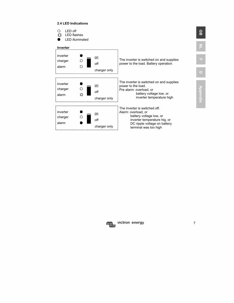
2.4 LED Indications LED off
LED flashes LED illuminated Inverter inverter on charger off alarm
charger only
The inverter is switched on and supplies power to the load. Battery operation.
inverter on charger off alarm
charger only
The inverter is switched on and supplies power to the load. Pre alarm: overload, or battery voltage low, or inverter temperature high
inverter on charger off alarm
charger only
The inverter is switched off. Alarm: overload, or battery voltage low, or inverter temperature hig, or DC ripple voltage on battery terminal was too high
8
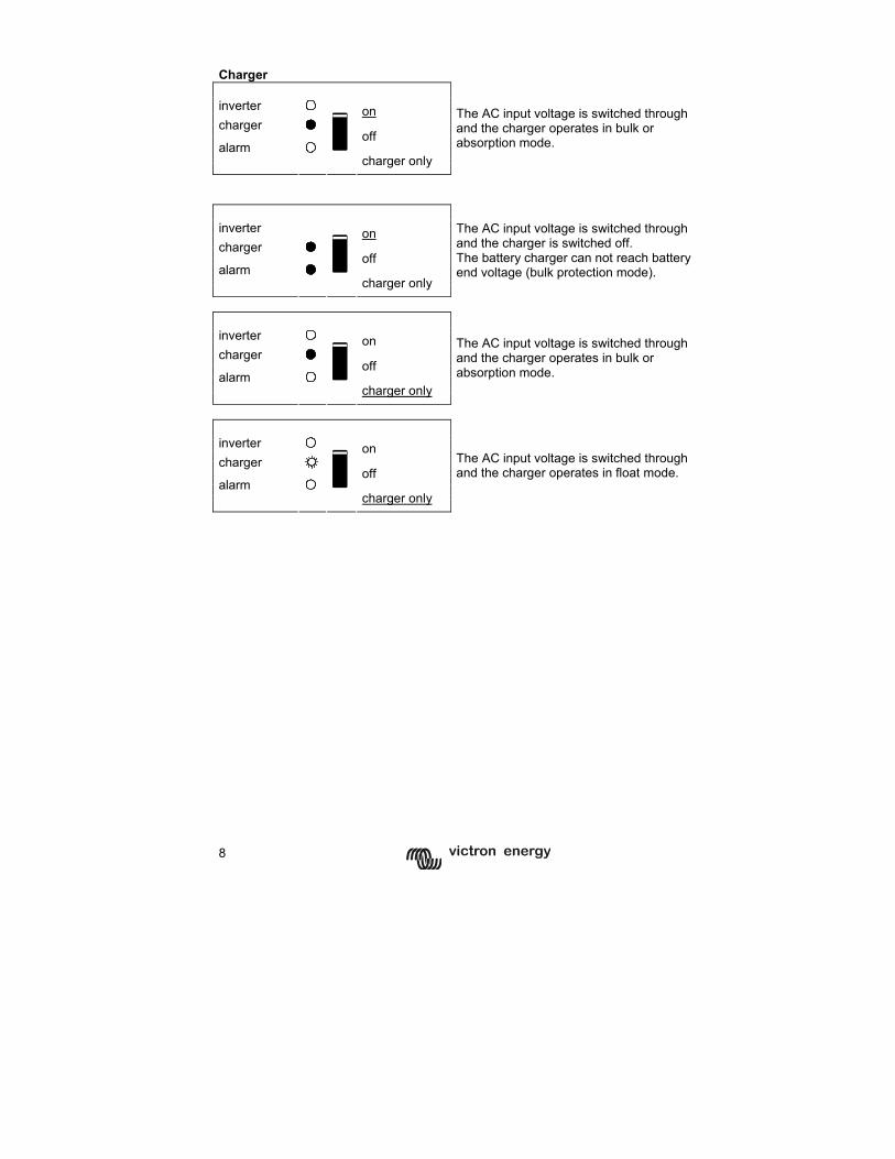
Charger inverter on charger off alarm
charger only
The AC input voltage is switched through and the charger operates in bulk or absorption mode.
inverter on charger off alarm
charger only
The AC input voltage is switched through and the charger is switched off. The battery charger can not reach battery end voltage (bulk protection mode).
inverter on charger off alarm
charger only
The AC input voltage is switched through and the charger operates in bulk or absorption mode.
inverter on charger off alarm
charger only
The AC input voltage is switched through and the charger operates in float mode.
9
GB
N
L F
D
Appendix
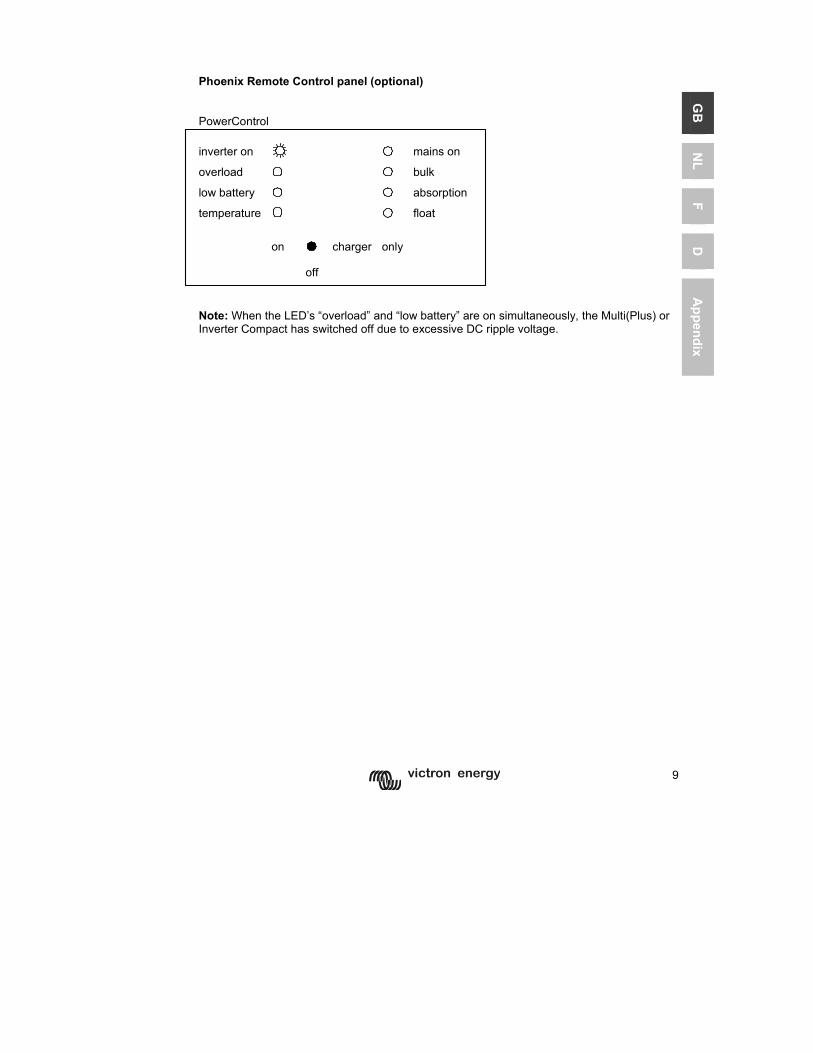
Phoenix Remote Control panel (optional) PowerControl inverter on mains on overload bulk
low battery absorption
temperature
float
on charger only
off
Note: When the LED’s “overload” and “low battery” are on simultaneously, the Multi(Plus) or Inverter Compact has switched off due to excessive DC ripple voltage.
10
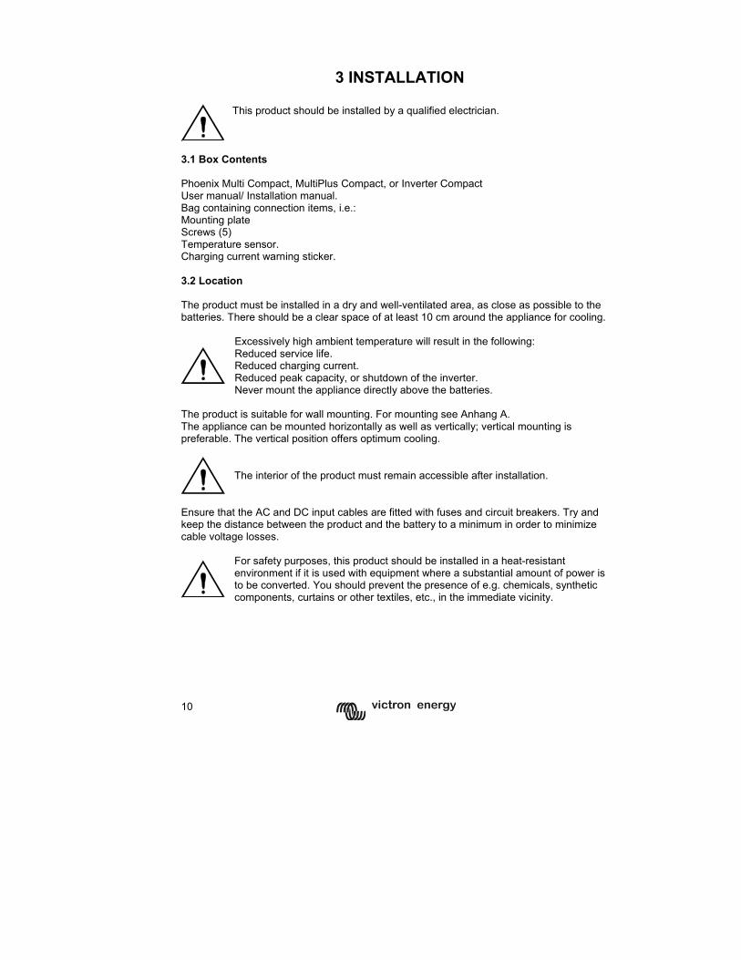
3 INSTALLATION
This product should be installed by a qualified electrician.
3.1 Box Contents Phoenix Multi Compact, MultiPlus Compact, or Inverter Compact User manual/ Installation manual. Bag containing connection items, i.e.: Mounting plate Screws (5) Temperature sensor. Charging current warning sticker. 3.2 Location The product must be installed in a dry and well-ventilated area, as close as possible to the batteries. There should be a clear space of at least 10 cm around the appliance for cooling.
Excessively high ambient temperature will result in the following: Reduced service life. Reduced charging current. Reduced peak capacity, or shutdown of the inverter. Never mount the appliance directly above the batteries.
The product is suitable for wall mounting. For mounting see Anhang A. The appliance can be mounted horizontally as well as vertically; vertical mounting is preferable. The vertical position offers optimum cooling.
The interior of the product must remain accessible after installation.
Ensure that the AC and DC input cables are fitted with fuses and circuit breakers. Try and keep the distance between the product and the battery to a minimum in order to minimize cable voltage losses.
For safety purposes, this product should be installed in a heat-resistant environment if it is used with equipment where a substantial amount of power is to be converted. You should prevent the presence of e.g. chemicals, synthetic components, curtains or other textiles, etc., in the immediate vicinity.
11
GB
N
L F
D
Appendix
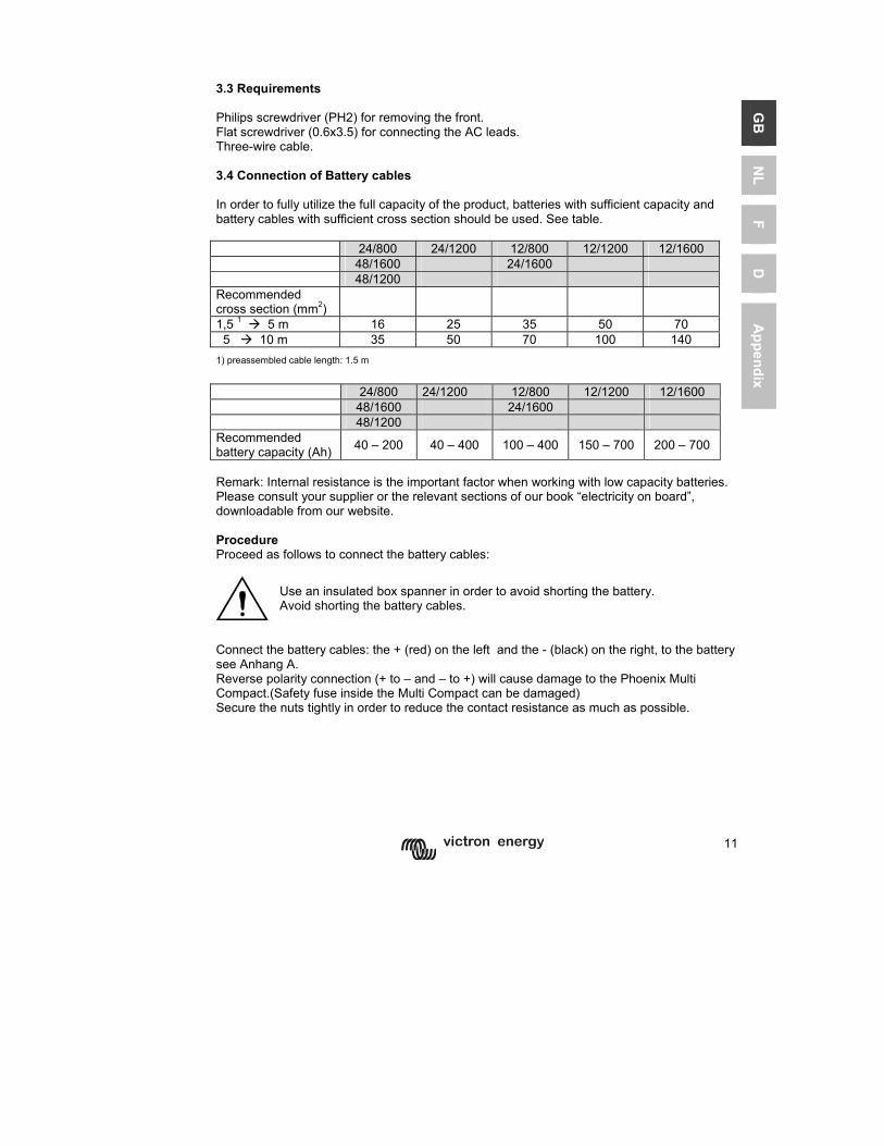
3.3 Requirements Philips screwdriver (PH2) for removing the front. Flat screwdriver (0.6x3.5) for connecting the AC leads. Three-wire cable. 3.4 Connection of Battery cables In order to fully utilize the full capacity of the product, batteries with sufficient capacity and battery cables with sufficient cross section should be used. See table. 24/800 24/1200 12/800 12/1200 12/1600 48/1600 24/1600 48/1200 Recommended cross section (mm2)
1,5 1 5 m 16 25 35 50 70 5 10 m 35 50 70 100 140 1) preassembled cable length: 1.5 m
24/800 24/1200 12/800 12/1200 12/1600 48/1600 24/1600 48/1200 Recommended battery capacity (Ah) 40 – 200 40 – 400 100 – 400 150 – 700 200 – 700
Remark: Internal resistance is the important factor when working with low capacity batteries. Please consult your supplier or the relevant sections of our book “electricity on board”, downloadable from our website. Procedure Proceed as follows to connect the battery cables:
Use an insulated box spanner in order to avoid shorting the battery. Avoid shorting the battery cables.
Connect the battery cables: the + (red) on the left and the - (black) on the right, to the battery see Anhang A. Reverse polarity connection (+ to – and – to +) will cause damage to the Phoenix Multi Compact.(Safety fuse inside the Multi Compact can be damaged) Secure the nuts tightly in order to reduce the contact resistance as much as possible.
12
3.5 Connection of the AC cabling
This is a Safety Class I product (supplied with a protective grounding terminal). Uninterruptible protective grounding must be provided at the AC input and/or output terminals and/or chassis grounding point located externally on the product. See the following instructions: a) The Phoenix Inverter Compact has a free floating AC output. The grounding point located externally on the product must be used to ground the chassis. The neutral output wire must be connected to ground to ensure proper functioning of a GFCI (Ground Fault Circuit Interrupter). b) Phoenix Multi / MultiPlus Compact : the output neutral wire will automatically be bonded to the chassis (with the output ground relay, see appendix 2) when no external AC source is available (backfeed / safety relay open and product running in inverter mode, see appendix 2). When an external AC source is provided, the ground relay opens before closure of the backfeed / safety relay. Once closed, the backfeed / safety relay ensures that the neutral to ground bond is provided by the external AC source. This is to ensure proper functioning of a GFCI to be installed in the AC output of the Multi/MultiPlus. - In a fixed (for example terrestrial) installation an uninterrupted chassis ground may be provided by the AC input ground wire. - In case of a mobile installation (connection to input AC with a shore power cord), the ground connection is lost when the shore power cord is unplugged. In this case the chassis of the product or the on - board section of the input ground wire must be connected to the frame (of the vehicle) or the ground plate or hull (of a boat). - Marine applications: due to the potential for galvanic corrosion it is in general not acceptable to connect the shore side ground to the ground plate or hull of the boat. The proper and safe solution is to install an isolation transformer.
The mains -input & output terminal connector G-ST18i can be found on the bottom of the Multi Compact, see appendix 1. The shore or mains cable must be connected to the G-ST18i connector with a three-wire cable. Use a three-wire cable with a flexible core and a cross section of 1.5 mm² (800VA) to 2.5 mm² (1600VA). Procedure Proceed as follows to connect the AC cables: The AC output cable can be connected directly to the G-ST18i male-connector. (the connector pulls out!) The terminal points are indicated clearly. From left to right: “N” (neutral), earth, and “L1” (phase). The AC input cable can be connected directly to the G-ST18I female-connector. (the connector pulls out!) The terminal points are indicated clearly. From left to right: “L1” (phase). earth, and “N” (neutral), Push the G-ST18i "input" connector into terminal connector (near to rear-side). Push the G-ST18i "output" connector into terminal connector (near to front-side).
13
GB
N
L F
D
Appendix
3.6 Optional Connections A number of optional connections are possible: Undo the four screws at the front of the enclosure and remove the front panel. 3.6.1 Second Battery The Phoenix Multi Compact / MultiPlus Compact has a connection for charging a starter battery. For connection see appendix 1
14
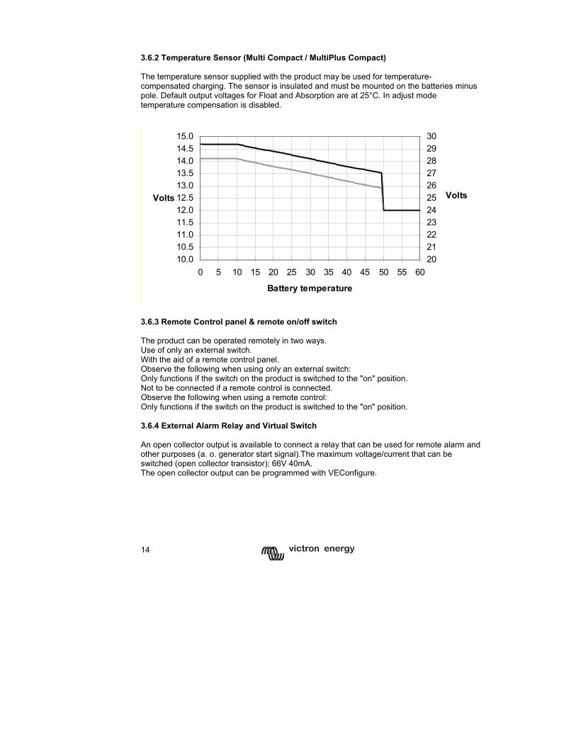
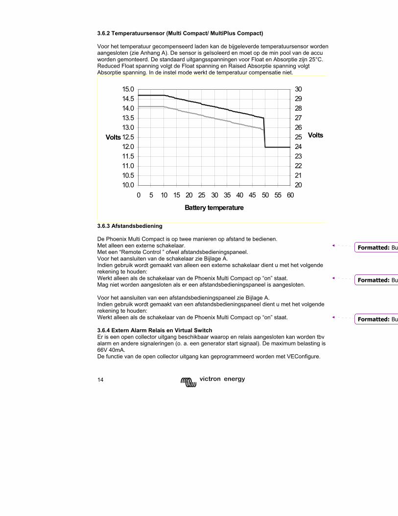
3.6.2 Temperature Sensor (Multi Compact / MultiPlus Compact) The temperature sensor supplied with the product may be used for temperature-compensated charging. The sensor is insulated and must be mounted on the batteries minus pole. Default output voltages for Float and Absorption are at 25°C. In adjust mode temperature compensation is disabled.
10.010.511.011.512.012.513.013.514.014.515.0
0 5 10 15 20 25 30 35 40 45 50 55 60
Battery temperature
Volts
2021222324252627282930
Volts
3.6.3 Remote Control panel & remote on/off switch The product can be operated remotely in two ways. Use of only an external switch. With the aid of a remote control panel. Observe the following when using only an external switch: Only functions if the switch on the product is switched to the "on" position. Not to be connected if a remote control is connected. Observe the following when using a remote control: Only functions if the switch on the product is switched to the "on" position. 3.6.4 External Alarm Relay and Virtual Switch An open collector output is available to connect a relay that can be used for remote alarm and other purposes (a. o. generator start signal).The maximum voltage/current that can be switched (open collector transistor): 66V 40mA. The open collector output can be programmed with VEConfigure.
15
GB
N
L F
D
Appendix
4 SETTINGS
Settings may only be changed by a qualified engineer Carefully read the instructions before changes are made. Batteries should be placed in a dry and well-ventilated area during charging.
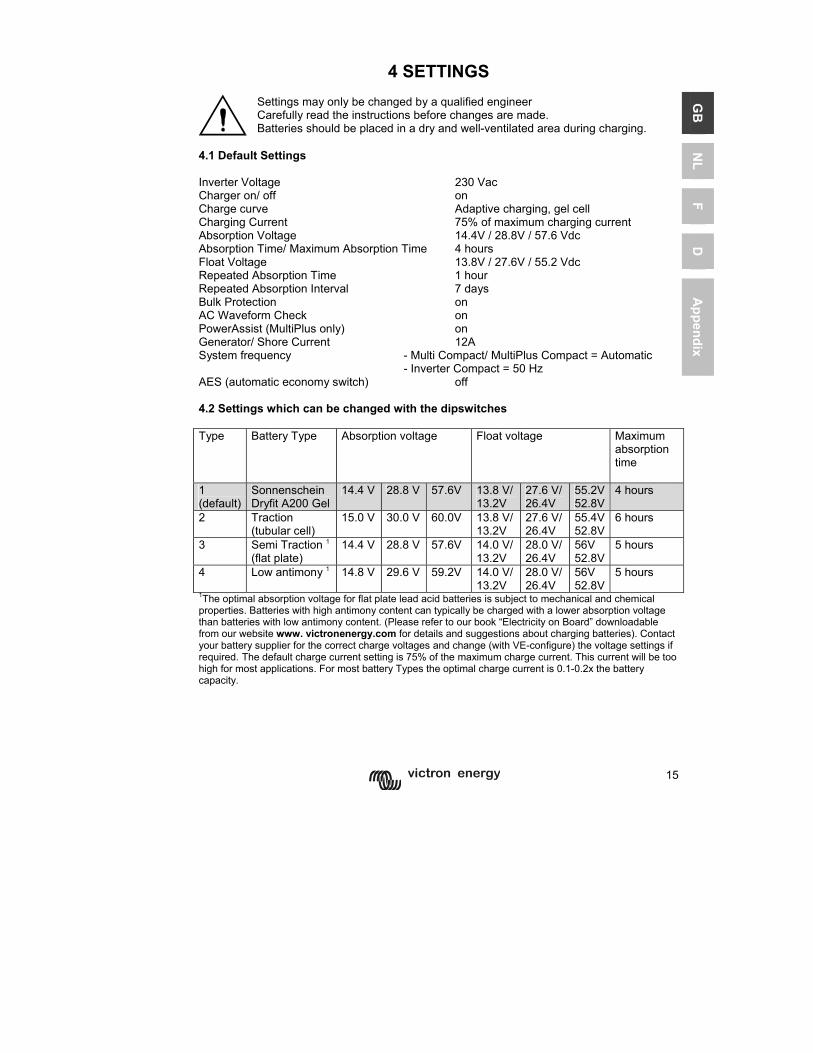
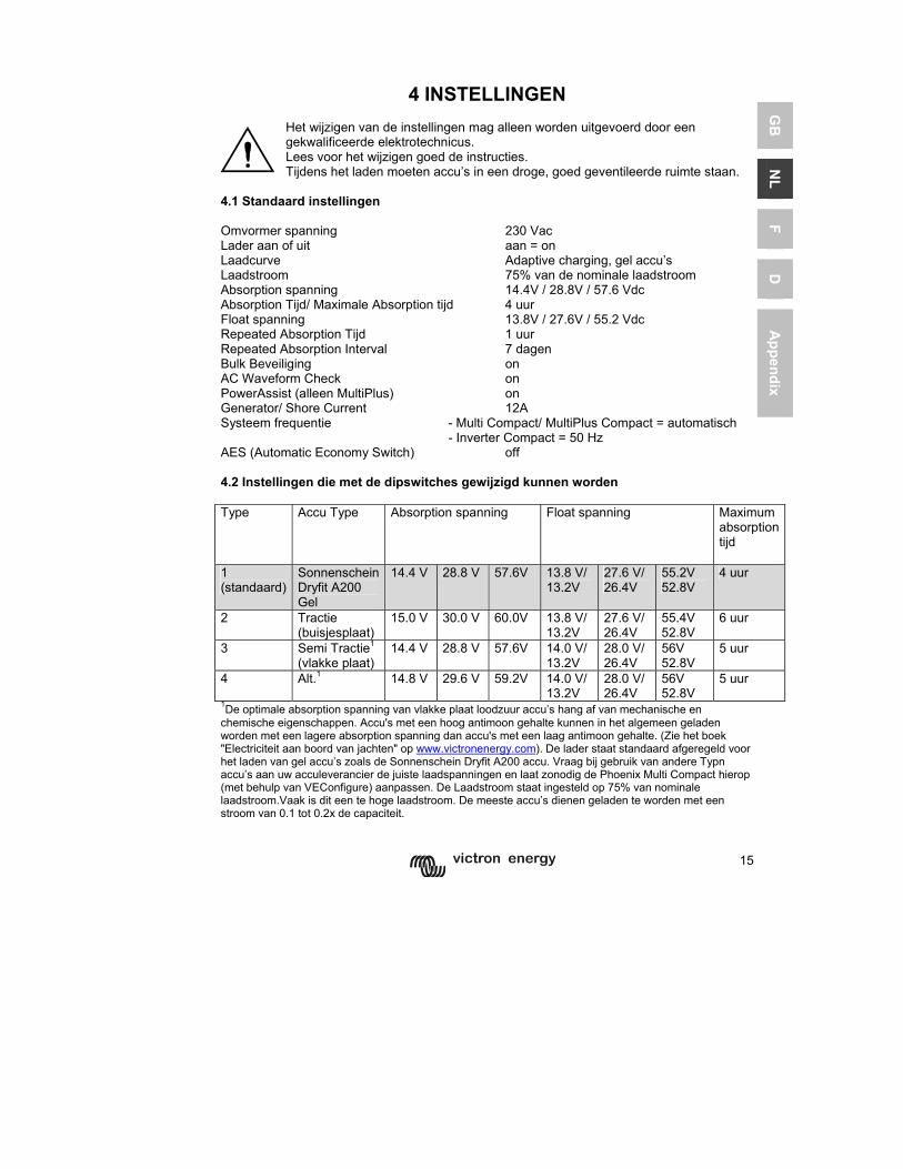
4.1 Default Settings Inverter Voltage 230 Vac Charger on/ off on Charge curve Adaptive charging, gel cell Charging Current 75% of maximum charging current Absorption Voltage 14.4V / 28.8V / 57.6 Vdc Absorption Time/ Maximum Absorption Time 4 hours Float Voltage 13.8V / 27.6V / 55.2 Vdc Repeated Absorption Time 1 hour Repeated Absorption Interval 7 days Bulk Protection on AC Waveform Check on PowerAssist (MultiPlus only) on Generator/ Shore Current 12A System frequency - Multi Compact/ MultiPlus Compact = Automatic
- Inverter Compact = 50 Hz AES (automatic economy switch) off 4.2 Settings which can be changed with the dipswitches Type Battery Type Absorption voltage Float voltage Maximum
absorption time
1 (default)
Sonnenschein Dryfit A200 Gel
14.4 V 28.8 V 57.6V 13.8 V/ 13.2V
27.6 V/ 26.4V
55.2V 52.8V
4 hours
2 Traction (tubular cell)
15.0 V 30.0 V 60.0V 13.8 V/ 13.2V
27.6 V/ 26.4V
55.4V 52.8V
6 hours
3 Semi Traction 1 (flat plate)
14.4 V 28.8 V 57.6V 14.0 V/ 13.2V
28.0 V/ 26.4V
56V 52.8V
5 hours
4 Low antimony 1 14.8 V 29.6 V 59.2V 14.0 V/ 13.2V
28.0 V/ 26.4V
56V 52.8V
5 hours
1The optimal absorption voltage for flat plate lead acid batteries is subject to mechanical and chemical properties. Batteries with high antimony content can typically be charged with a lower absorption voltage than batteries with low antimony content. (Please refer to our book “Electricity on Board” downloadable from our website www. victronenergy.com for details and suggestions about charging batteries). Contact your battery supplier for the correct charge voltages and change (with VE-configure) the voltage settings if required. The default charge current setting is 75% of the maximum charge current. This current will be too high for most applications. For most battery Types the optimal charge current is 0.1-0.2x the battery capacity.
16
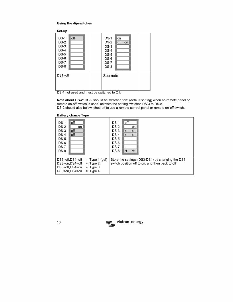
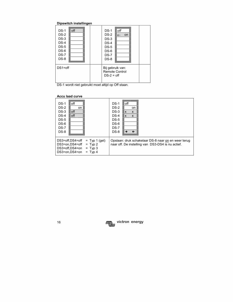
Using the dipswitches Set-up DS-1 off DS-2 DS-3 DS-4 DS-5 DS-6 DS-7 DS-8
DS-1 off DS-2 ← onDS-3 DS-4 DS-5 DS-6 DS-7 DS-8
DS1=off
See note
DS-1 not used and must be switched to Off. Note about DS-2: DS-2 should be switched “on” (default setting) when no remote panel or remote on-off switch is used. activate the setting switches DS-3 to DS-8. DS-2 should also be switched off to use a remote control panel or remote on-off switch. Battery charge Type DS-1 off DS-2 on DS-3 off DS-4 off DS-5 DS-6 DS-7 DS-8
DS-1 off DS-2 onDS-3 x x DS-4 x x DS-5 DS-6 DS-7 DS-8
DS3=off,DS4=off = Type 1 (gel) DS3=on,DS4=off = Type 2 DS3=off,DS4=on = Type 3 DS3=on,DS4=on = Type 4
Store the settings (DS3-DS4) by changing the DS8 switch position off to on, and then back to off
17
GB
N
L F
D
Appendix
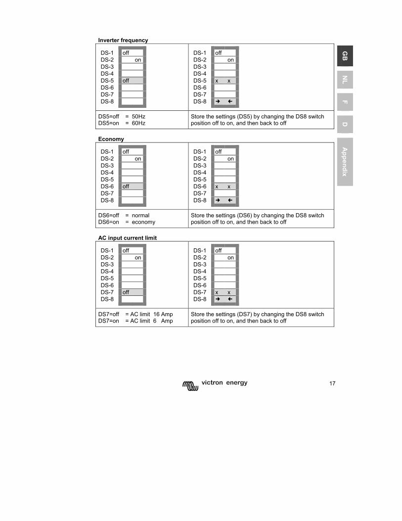
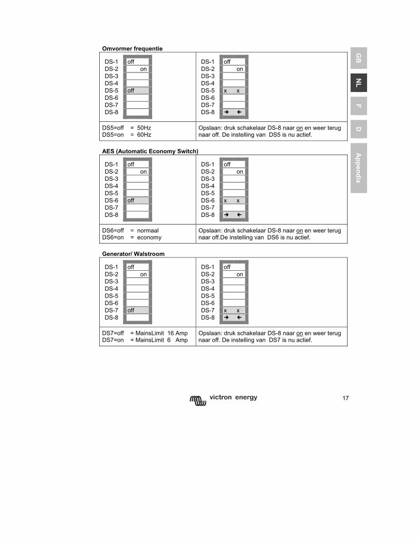
Inverter frequency DS-1 off DS-2 on DS-3 DS-4 DS-5 off DS-6 DS-7 DS-8
DS-1 off DS-2 onDS-3 DS-4 DS-5 x x DS-6 DS-7 DS-8
DS5=off = 50Hz DS5=on = 60Hz
Store the settings (DS5) by changing the DS8 switch position off to on, and then back to off
Economy DS-1 off DS-2 on DS-3 DS-4 DS-5 DS-6 off DS-7 DS-8
DS-1 off DS-2 onDS-3 DS-4 DS-5 DS-6 x x DS-7 DS-8
DS6=off = normal DS6=on = economy
Store the settings (DS6) by changing the DS8 switch position off to on, and then back to off
AC input current limit DS-1 off DS-2 on DS-3 DS-4 DS-5 DS-6 DS-7 off DS-8
DS-1 off DS-2 onDS-3 DS-4 DS-5 DS-6 DS-7 x x DS-8
DS7=off = AC limit 16 Amp DS7=on = AC limit 6 Amp
Store the settings (DS7) by changing the DS8 switch position off to on, and then back to off
18
4.3 The adaptive charge curve
64 32
60 30 56 28
52 26
48 24
44 22 40 20
C h a rg e c u rre n t
0%
20%
40%
60%
80%
100%
120%
T im e
A m p s
C h a rg e v o lta g e
10
11
12
13
14
15
16
T im e
V o lts
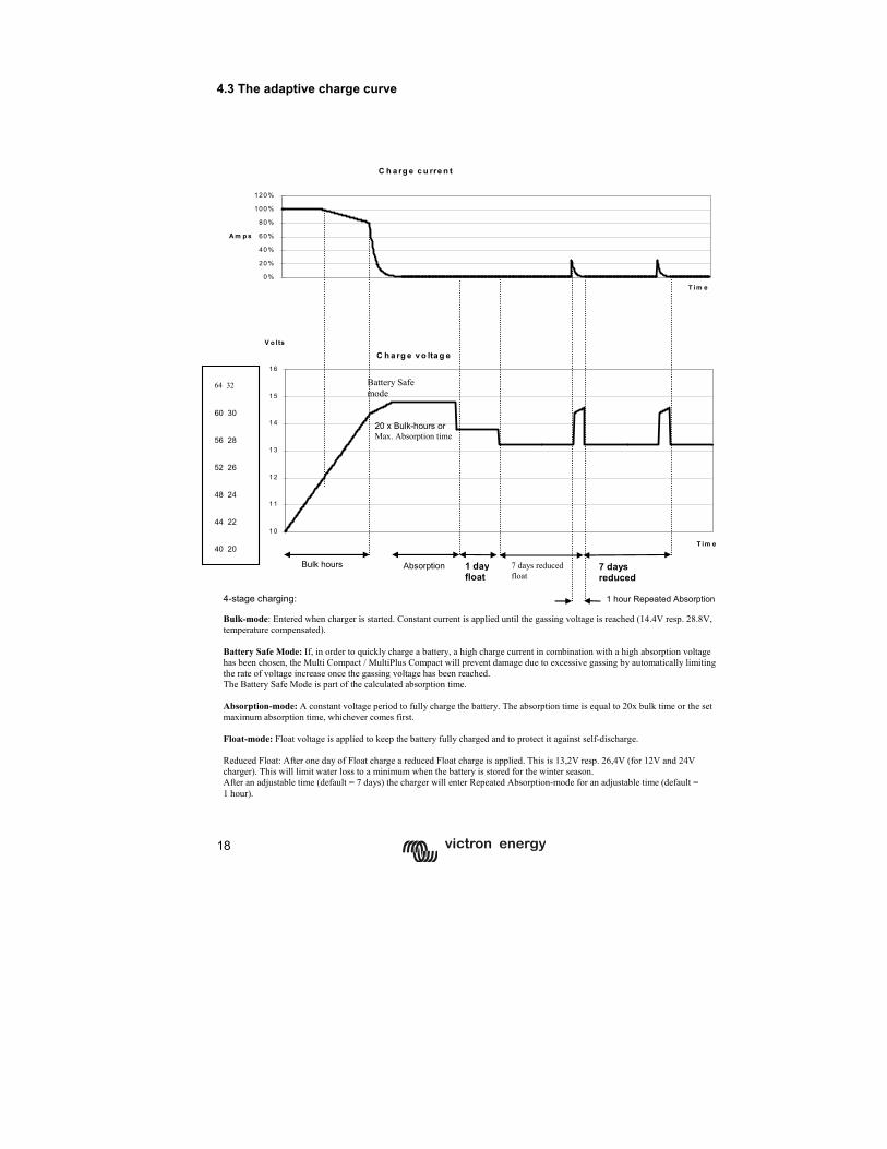
4-stage charging:
Bulk-mode: Entered when charger is started. Constant current is applied until the gassing voltage is reached (14.4V resp. 28.8V, temperature compensated). Battery Safe Mode: If, in order to quickly charge a battery, a high charge current in combination with a high absorption voltage has been chosen, the Multi Compact / MultiPlus Compact will prevent damage due to excessive gassing by automatically limiting the rate of voltage increase once the gassing voltage has been reached. The Battery Safe Mode is part of the calculated absorption time. Absorption-mode: A constant voltage period to fully charge the battery. The absorption time is equal to 20x bulk time or the set maximum absorption time, whichever comes first. Float-mode: Float voltage is applied to keep the battery fully charged and to protect it against self-discharge. Reduced Float: After one day of Float charge a reduced Float charge is applied. This is 13,2V resp. 26,4V (for 12V and 24V charger). This will limit water loss to a minimum when the battery is stored for the winter season. After an adjustable time (default = 7 days) the charger will enter Repeated Absorption-mode for an adjustable time (default = 1 hour).
Bulk hours 1 dayfloat
7 days reduced float
Absorption
1 hour Repeated Absorption
7 days reduced
20 x Bulk-hours or Max. Absorption time
Battery Safe mode
64 32 60 30 56 28 52 26 48 24 44 22 40 20
19
GB
N
L F
D
Appendix
4.4 Setting the Charger (Multi Compact / MultiPlus Compact only) 4.4.1 Preprogrammed charge curves (can be changed with VEConfigure only). Please refer to our book “Electricity on Board” downloadable from our website www.victronenergy.com for details and suggestions about charging batteries. The Phoenix Multi Compact/ MultiPlus Compact has 3 pre-programmed charge curves: Fixed, 3 state charge curve The absorption period is a fixed preset period. Following the absorption mode, the charger switches to float. In order to “refresh” the battery, the charger periodically switches back to absorption. Adaptive charge curve The absorption period depends on the length of the bulk charge period (see par. 4.3). This is followed by a float phase lasting 24 hours, after which the voltage is reduced by an additional 0,8 V resp. 1,6 V for 12 V resp. 24 V batteries (reduced float). As with the Fixed-charge curve, the charger will periodically switch back to absorption. Adaptive charge curve with BatterySafe mode (default setting) If, in order to quickly charge a battery, a high charge current in combination with a high absorption voltage has been chosen, the Phoenix charger will prevent damage due to excessive gassing by automatically limiting the rate of voltage increase once the gassing voltage has been reached. 4.4.2 Other settings Absorption time (default: 4 hours) The Absorption setting defines the fixed absorption period in the case of the fixed charge curve, and the maximum absorption time in the case of the adaptive charge curve. The (maximum) absorption time can be set from 1 to 8 hours. Float Voltage (default: 14.4V / 28.8V) The float voltage can be set from 12V to16V, respectively from 24V to 32V, in 0.05V increments. Repeated Absorption When in float, the charger will periodically switch back to Absorption to “refresh” the battery. Repeated Absorption Time (default: 1 hour) The repeated absorption time can be set from 1 to 72 quarters of an hour. Repeated Absorption Interval (default: 7 days) The repeated absorption interval can be set from 1 to 45 days.
20
4.5 Special Settings (can be changed with VEConfigure only) Bulk Protection On / Off (default: on) If the charger has not reached the absorption voltage after 10 hours' charging in the bulk phase, the battery may be defective. In order to prevent further damage, the charger will automatically cut out after 10 hours' bulk. The “bulk” LED will start to flash (Phoenix Inverter Control). AC Waveform Check (default: on) The Phoenix Multi Compact checks if the mains voltage has not only the correct voltage, but also the correct shape. When the Phoenix Multi Compact does not function properly on a generator this function can be disabled. Note: Additionally, by disabling AC waveform check the AC low disconnect is ignored when the load current is higher than 1.5 times the AC input current limit. This to prevent unnecessary switching to inverter due to a voltage drop when a high load is connected. PowerControl – Dealing with limited generator or shore side power The Multi Compact is a very powerful battery charger. It will therefore draw a lot of current from the generator or shore side supply. With the Phoenix Multi Control Panel (PMV) a maximum generator or shore current can be set. The Multi Compact will then take account of other AC loads and use whatever is extra for charging, thus preventing the generator or shore supply from being overloaded. It is also possible to set the max. generator/ shore current internally. The generator/shore current limit can be set at from 2 to 16A. The remote control panel setting overrides the internal setting. PowerAssist – Boosting the capacity of shore or generator power (MultiPlus only, default: on) The feature that distinguishes the Phoenix MultiPlus Compact from the standard Multi Compact is PowerAssist. This feature takes the principle of PowerControl to a further dimension allowing the MultiPlus Compact to supplement the capacity of the alternative source. Where peak power is so often required only for a limited period, it is possible to reduce the size of generator needed or conversely enable more to be achieved from the typically limited shore connection. When the load reduces, the spare power is used to recharge the battery. Note 1: Minimum shore current 2 A or generator capacity equal to the Multi rating required for proper operation of PowerAssist. Note 2: Some modern AC generators use a static inverter to generate the AC output. Some of these generators also reduce rpm when operating with reduced load. By enabling the Dynamic Current Limit function (VEConfigure) the MultiPlus Compact can be used to assist the generator when suddenly a high load is connected. External Alarm Relay and Virtual Switch (default: disabled) An open collector output is available to connect a relay that can be used for remote alarm and other purposes (a. o. generator start signal).The maximum voltage/current that can be switched (open collector transistor): 66V 40mA. The open collector output can be programmed with VEConfigure. 4.6 Maintenance The Phoenix Multi Compact does not require specific maintenance. Annual checking of all connections and eventually removal of dust suffices. Protect the product from humidity and oil fumes and keep it clean.
21
GB
N
L F
D
Appendix
5 TROUBLE SHOOTING TABLE
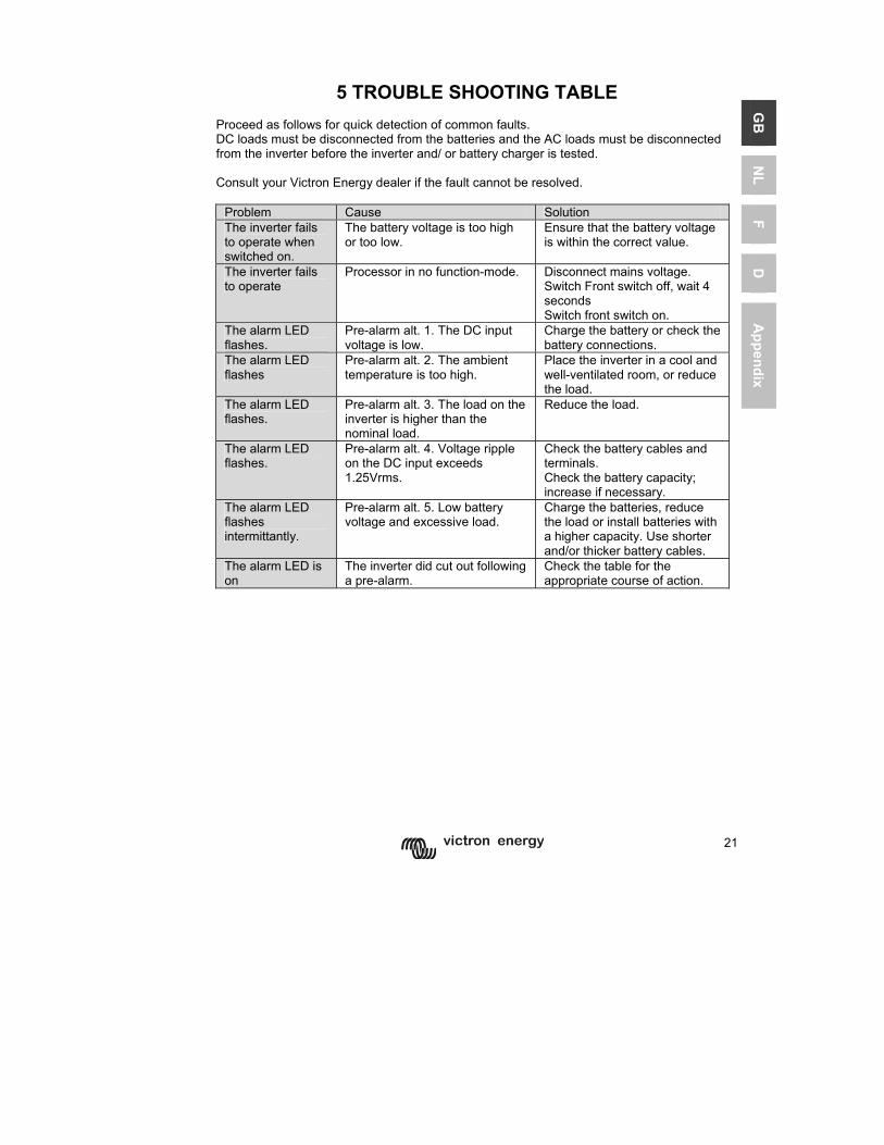
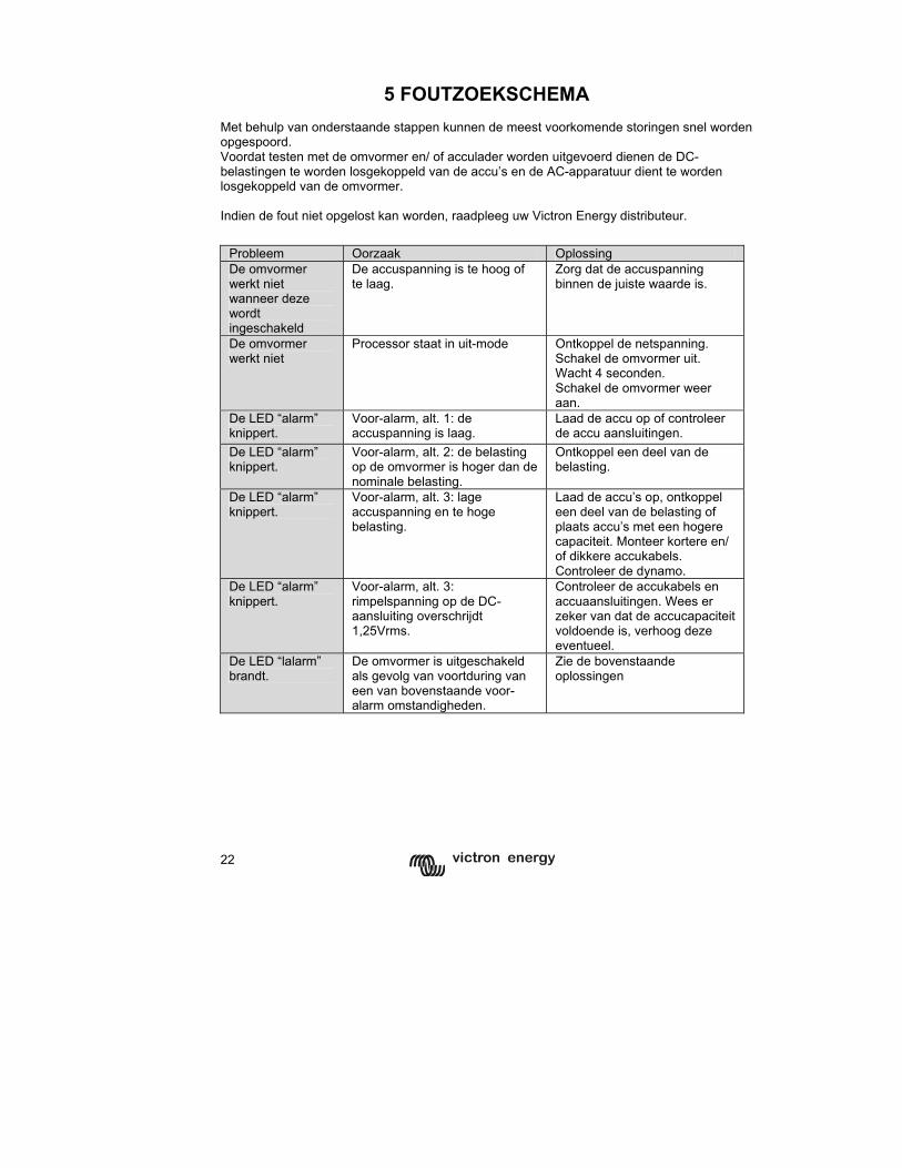
Proceed as follows for quick detection of common faults. DC loads must be disconnected from the batteries and the AC loads must be disconnected from the inverter before the inverter and/ or battery charger is tested. Consult your Victron Energy dealer if the fault cannot be resolved.
Problem Cause Solution The inverter fails to operate when switched on.
The battery voltage is too high or too low.
Ensure that the battery voltage is within the correct value.
The inverter fails to operate
Processor in no function-mode. Disconnect mains voltage. Switch Front switch off, wait 4 seconds Switch front switch on.
The alarm LED flashes.
Pre-alarm alt. 1. The DC input voltage is low.
Charge the battery or check the battery connections.
The alarm LED flashes
Pre-alarm alt. 2. The ambient temperature is too high.
Place the inverter in a cool and well-ventilated room, or reduce the load.
The alarm LED flashes.
Pre-alarm alt. 3. The load on the inverter is higher than the nominal load.
Reduce the load.
The alarm LED flashes.
Pre-alarm alt. 4. Voltage ripple on the DC input exceeds 1.25Vrms.
Check the battery cables and terminals. Check the battery capacity; increase if necessary.
The alarm LED flashes intermittantly.
Pre-alarm alt. 5. Low battery voltage and excessive load.
Charge the batteries, reduce the load or install batteries with a higher capacity. Use shorter and/or thicker battery cables.
The alarm LED is on
The inverter did cut out following a pre-alarm.
Check the table for the appropriate course of action.
22
Problem Cause Solution
The AC input voltage or frequency is out of range.
Ensure that the input voltage is between 185 Vac and 265 Vac, and that the frequency matches the setting.
The charger is not functioning
The thermal circuit breaker has tripped.
Reset the 16 A thermal circuit breaker.
Incorrect charging current. Set the charging current at between 0.1 and 0.2x battery capacity.
A defective battery connection. Check the battery terminals.
The absorption voltage has been set to an incorrect value.
Adjust the absorption voltage to the correct value.
The float voltage has been set to an incorrect value.
Adjust the float voltage to the correct value.
The battery is not being charged fully.
The internal DC fuse is defective. Inverter is damaged.
The absorption voltage has been set to an incorrect value.
Adjust the absorption voltage to the correct value.
The float voltage has been set to an incorrect value.
Adjust the float voltage to the correct value.
A defective battery. Replace the battery.
The battery is too small. Reduce the charging current or use a battery with a higher capacity.
The battery is overcharged.
The battery is too hot. Connect a temperature sensor. Alt. 1: Battery overtemperature (> 50°C)
- Allow battery to cool down - Place battery in a cool environment - Check for shorted cells
Battery charge current drops to 0 when the absorption voltage is reached
Alt 2: Battery temperature sensor faulty
Unplug battery temperature sensor from the Multi. Reset the Multi by switching it off, then wait for 4 seconds and switch it on again If the Multi now charges normally, the battery temperature sensor is faulty and needs to be replaced
23
GB
N
L F
D
Appendix
6 TECHNICAL DATA
6.1 GENERAL Ventilation Forced cooling (internal) Temperature limits - operation - storage
-20 – +50 °C -25 – +60 °C Output short circuit Overload Battery voltage too high Battery voltage too low 230V mains on inverter output DC Input voltage ripple too high
transformer Electronics & Power stage
Protection
Temperature too high
Battery (if sensor connected) Humidity 0 - 95% EMC Electromagnetic compliance
EMC 89/336 EEC Emission EN 55014 (1993) en EN50081-1
EN61000-3-2 EN61000-3-3
Immunity EN 55104 (1995) Safety Low voltage-norm:
73/23/EEG en 93/68/EEG EN60335-1 en EN60335-2-29
Automotive 95/54/EC
24
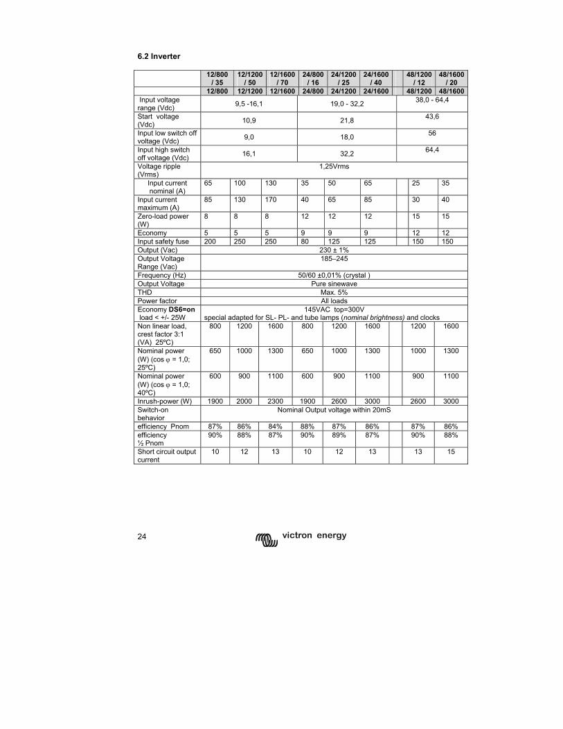
6.2 Inverter 12/800
/ 35 12/1200
/ 50 12/1600
/ 70 24/800
/ 16 24/1200
/ 25 24/1600
/ 40
48/1200 / 12
48/1600/ 20
12/800 12/1200 12/1600 24/800 24/1200 24/1600 48/1200 48/1600 Input voltage range (Vdc) 9,5 -16,1 19,0 - 32,2 38,0 - 64,4
Start voltage (Vdc) 10,9 21,8 43,6
Input low switch off voltage (Vdc) 9,0 18,0 56
Input high switch off voltage (Vdc) 16,1 32,2 64,4
Voltage ripple (Vrms)
1,25Vrms
Input current nominal (A)
65 100 130 35 50 65 25 35
Input current maximum (A)
85 130 170 40 65 85 30 40
Zero-load power (W)
8 8 8 12 12 12 15 15
Economy 5 5 5 9 9 9 12 12 Input safety fuse 200 250 250 80 125 125 150 150 Output (Vac) 230 ± 1% Output Voltage Range (Vac)
185–245
Frequency (Hz) 50/60 ±0,01% (crystal ) Output Voltage Pure sinewave THD Max. 5% Power factor All loads Economy DS6=on load < +/- 25W
145VAC top=300V special adapted for SL- PL- and tube lamps (nominal brightness) and clocks
Non linear load, crest factor 3:1 (VA) 25ºC)
800 1200 1600 800 1200 1600 1200 1600
Nominal power (W) (cos ϕ = 1,0; 25ºC)
650 1000 1300 650 1000 1300 1000 1300
Nominal power (W) (cos ϕ = 1,0; 40ºC)
600 900 1100 600 900 1100 900 1100
Inrush-power (W) 1900 2000 2300 1900 2600 3000 2600 3000 Switch-on behavior
Nominal Output voltage within 20mS
efficiency Pnom 87% 86% 84% 88% 87% 86% 87% 86% efficiency ½ Pnom
90% 88% 87% 90% 89% 87% 90% 88%
Short circuit output current
10 12 13 10 12 13 13 15
25
GB
N
L F
D
Appendix
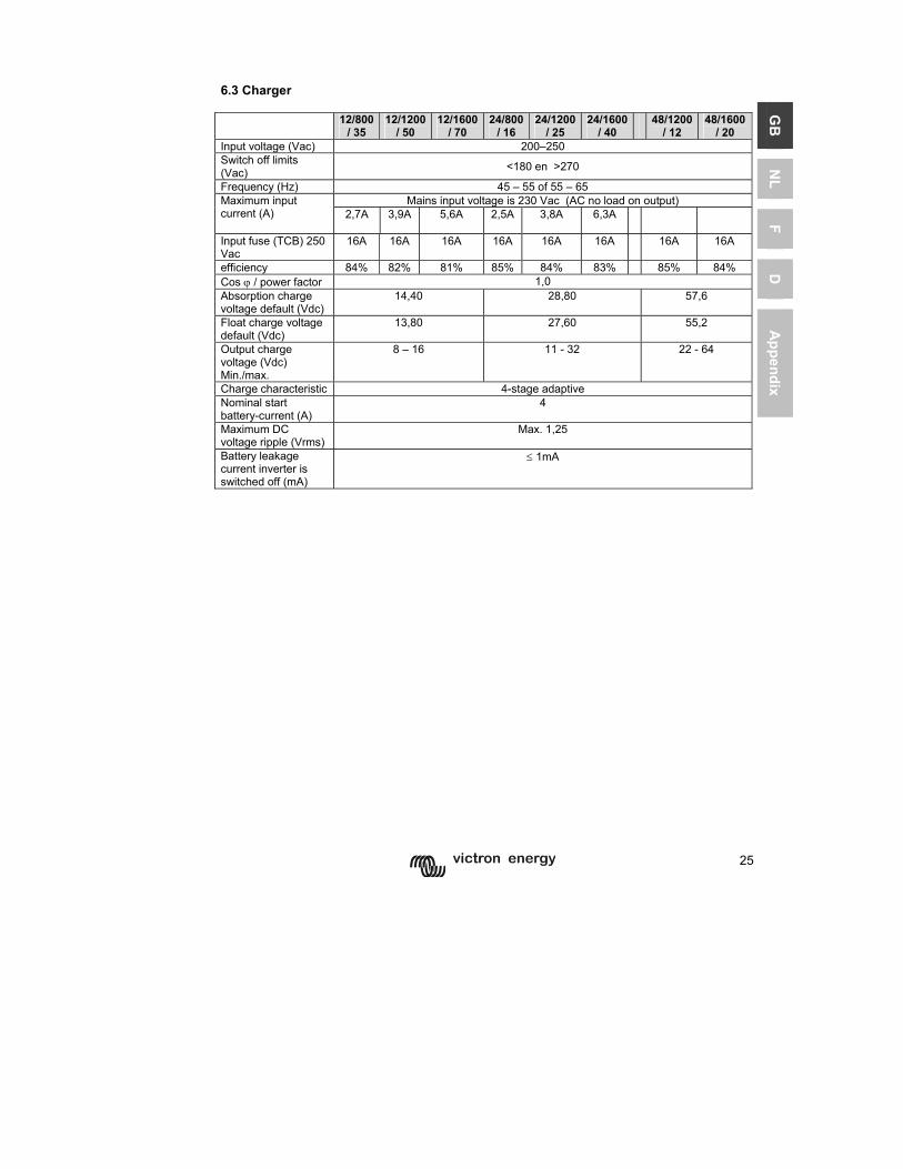
6.3 Charger 12/800
/ 35 12/1200
/ 50 12/1600
/ 70 24/800
/ 16 24/1200
/ 25 24/1600
/ 40
48/1200 / 12
48/1600/ 20
Input voltage (Vac) 200–250 Switch off limits (Vac) <180 en >270
Frequency (Hz) 45 – 55 of 55 – 65 Mains input voltage is 230 Vac (AC no load on output) Maximum input
current (A) 2,7A 3,9A 5,6A
2,5A 3,8A 6,3A
Input fuse (TCB) 250 Vac
16A 16A 16A 16A 16A 16A 16A 16A
efficiency 84% 82% 81% 85% 84% 83% 85% 84% Cos ϕ / power factor 1,0 Absorption charge voltage default (Vdc)
14,40 28,80 57,6
Float charge voltage default (Vdc)
13,80 27,60 55,2
Output charge voltage (Vdc) Min./max.
8 – 16 11 - 32 22 - 64
Charge characteristic 4-stage adaptive Nominal start battery-current (A)
4
Maximum DC voltage ripple (Vrms)
Max. 1,25
Battery leakage current inverter is switched off (mA)
≤ 1mA
26
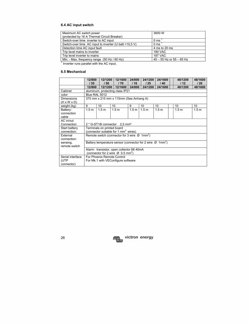
6.4 AC input switch Maximum AC switch power (protected by 16 A Thermal Circuit Breaker)
3600 W
Switch-over time inverter to AC input 0 ms 1 Switch-over time AC input to inverter (U batt >10,5 V) 0 ms 1 Detection time AC input fault 4 ms to 20 ms Trip level mains to inverter 180 VAC Trip level inverter to mains 187 VAC Min. - Max. frequency range (50 Hz / 60 Hz) 45 – 55 Hz or 55 – 65 Hz
1 Inverter runs parallel with the AC input. 6.5 Mechanical 12/800
/ 35 12/1200
/ 50 12/1600
/ 70 24/800
/ 16 24/1200
/ 25 24/1600
/ 40 48/1200
/ 12 48/1600
/ 20 12/800 12/1200 12/1600 24/800 24/1200 24/1600 48/1200 48/1600Cabinet aluminum, protecting class IP21 color Blue RAL 5012 Dimensions (H x W x D)
375 mm x 215 mm x 115mm (See Anhang A)
weight (kg) 9 10 10 9 10 10 10 10 Battery-connection cable
1.5 m 1.5 m 1.5 m 1.5 m 1.5 m 1.5 m 1.5 m 1.5 m
AC in/out Connection
2 * G-ST18i connector 2,5 mm²
Start battery connection:
Terminals on printed board (connector suitable for 1 mm2 wires) Remote switch (connector for 3 wire Ø 1mm2)
Battery temperature sensor (connector for 2 wire Ø 1mm2)
External connection: sensing, remote switch
Alarm: transistor, open collector 66 40mA (connector for 2 wire Ø 0,5 mm2)
Serial interface (UTP connector)
For Phoenix Remote Control For Mk.1 with VEConfigure software
1
GB
N
L F
D
Appendix
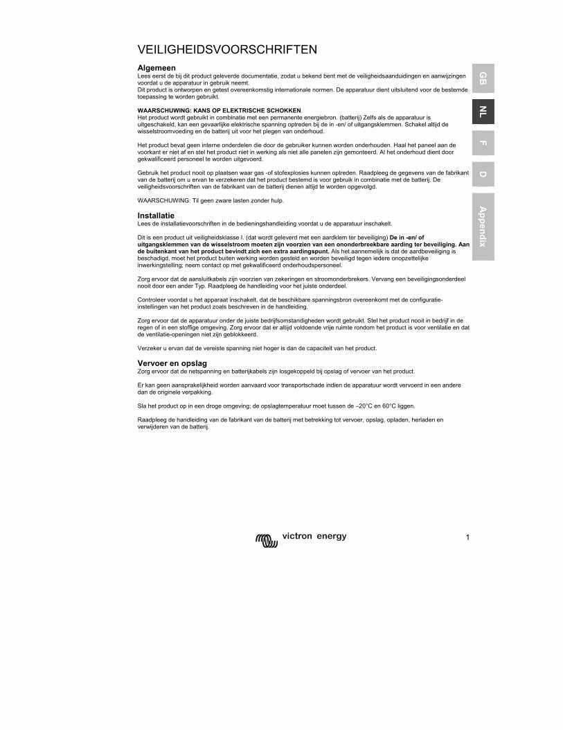
VEILIGHEIDSVOORSCHRIFTEN Algemeen Lees eerst de bij dit product geleverde documentatie, zodat u bekend bent met de veiligheidsaanduidingen en aanwijzingen voordat u de apparatuur in gebruik neemt. Dit product is ontworpen en getest overeenkomstig internationale normen. De apparatuur dient uitsluitend voor de bestemde toepassing te worden gebruikt. WAARSCHUWING: KANS OP ELEKTRISCHE SCHOKKEN. Het product wordt gebruikt in combinatie met een permanente energiebron. (batterij) Zelfs als de apparatuur is uitgeschakeld, kan een gevaarlijke elektrische spanning optreden bij de in -en/ of uitgangsklemmen. Schakel altijd de wisselstroomvoeding en de batterij uit voor het plegen van onderhoud. Het product bevat geen interne onderdelen die door de gebruiker kunnen worden onderhouden. Haal het paneel aan de voorkant er niet af en stel het product niet in werking als niet alle panelen zijn gemonteerd. Al het onderhoud dient door gekwalificeerd personeel te worden uitgevoerd. Gebruik het product nooit op plaatsen waar gas -of stofexplosies kunnen optreden. Raadpleeg de gegevens van de fabrikant van de batterij om u ervan te verzekeren dat het product bestemd is voor gebruik in combinatie met de batterij. De veiligheidsvoorschriften van de fabrikant van de batterij dienen altijd te worden opgevolgd. WAARSCHUWING: Til geen zware lasten zonder hulp. Installatie Lees de installatievoorschriften in de bedieningshandleiding voordat u de apparatuur inschakelt. Dit is een product uit veiligheidsklasse I. (dat wordt geleverd met een aardklem ter beveiliging) De in -en/ of uitgangsklemmen van de wisselstroom moeten zijn voorzien van een ononderbreekbare aarding ter beveiliging. Aan de buitenkant van het product bevindt zich een extra aardingspunt. Als het aannemelijk is dat de aardbeveiliging is beschadigd, moet het product buiten werking worden gesteld en worden beveiligd tegen iedere onopzettelijke inwerkingstelling; neem contact op met gekwalificeerd onderhoudspersoneel. Zorg ervoor dat de aansluitkabels zijn voorzien van zekeringen en stroomonderbrekers. Vervang een beveiligingsonderdeel nooit door een ander Typ. Raadpleeg de handleiding voor het juiste onderdeel. Controleer voordat u het apparaat inschakelt, dat de beschikbare spanningsbron overeenkomt met de configuratie-instellingen van het product zoals beschreven in de handleiding. Zorg ervoor dat de apparatuur onder de juiste bedrijfsomstandigheden wordt gebruikt. Stel het product nooit in bedrijf in de regen of in een stoffige omgeving. Zorg ervoor dat er altijd voldoende vrije ruimte rondom het product is voor ventilatie en dat de ventilatie-openingen niet zijn geblokkeerd. Verzeker u ervan dat de vereiste spanning niet hoger is dan de capaciteit van het product. Vervoer en opslag Zorg ervoor dat de netspanning en batterijkabels zijn losgekoppeld bij opslag of vervoer van het product. Er kan geen aansprakelijkheid worden aanvaard voor transportschade indien de apparatuur wordt vervoerd in een andere dan de originele verpakking. Sla het product op in een droge omgeving; de opslagtemperatuur moet tussen de –20°C en 60°C liggen. Raadpleeg de handleiding van de fabrikant van de batterij met betrekking tot vervoer, opslag, opladen, herladen en verwijderen van de batterij.
2
1 BESCHRIJVING
1.1 Algemeen Multi Compact -functioneel (alleen Multi Compact/ MultiPlus Compact) De basis van de Multi Compact is een zeer krachtige sinusomvormer, acculader en omschakelautomaat in een compacte behuizing. Daarnaast heeft de Multi Compact / MultiPlus Compact een groot aantal vaak unieke mogelijkheden, o.a. PowerControl en PowerAssist. Automatisch en onderbrekingsvrij omschakelen (alleen Multi Compact/ MultiPlus Compact) In geval van een netspanningstoring of wanneer het aggregaat wordt uitgeschakeld zal de Multi Compact overschakelen van lader bedrijf op omvormer bedrijf en de voeding van de aangesloten apparaten overnemen. Dit gaat zo snel dat computers en andere elektronische apparaten ongestoord blijven functioneren. De maximale stroom die geschakeld kan worden bedraagt 16 A Multi Compact. PowerControl – Maximaal benutten van beperkte walstroom (alleen Multi Compact/ MultiPlus Compact) De Multi Compact kan enorm veel laadstroom leveren en dus grote accubatterijen laden. Dat betekent een zware belasting voor de wal aansluiting of het aggregaat. Met het Phoenix Multi Control (bedieningspaneel) kan een maximale wal- of aggregaatstroom ingesteld worden. De Multi Compact houdt dan rekening met andere stroomverbruikers en gebruikt voor het laden alleen de stroom die nog ‘over’ is. PowerAssist – Doe meer met Uw aggregaat of walstroom: de unieke “meehelp” functie van de MultiPlus Compact Met de MultiPlus Compact kunt U nog een stap verder gaan. De MultiPlus Compact werkt parallel met het aggregaat of de walaansluiting en verdubbelt het beschikbare vermogen. Tijdelijk te weinig stroom? De MultiPlus Compact haalt extra energie uit de accu en helpt mee! Nog stroom over? De MultiPlus Compact maakt er gebruik van om de accu te laden. U stelt de walstroom in met een simpele 0 tot 16 A draaiknop op het Phoenix Multi Control. Opm 1: Igv parallel bedrijf met een generator mag het vermogen van de generator niet minder zijn dan 75% van het vermogen van de Multi(Plus) Compact. (voorbeeld: een generator. geschikt voor parallel bedrijf met een Multi(Plus) Compact 12/1200/50 moet een vermogen van minstens 900 VA hebben) Opm 2: De uitgangsspanning van een generator kan sterk vervormd zijn. In dat geval moet de “AC waveform check” uitgezet worden. Zie p 20.
3
GB
N
L F
D
Appendix
1.2 Acculader (alleen Multi Compact / MultiPlus Compact) Adaptieve 4-traps laadkarakteristiek: bulk – absorption – float – opslag Het microprocessor gestuurde ‘adaptieve’ accu management systeem kan afgeregeld worden voor verschillende soorten accu’s. De adaptieve functie past het laadproces automatisch aan het gebruik van de accu. De juiste hoeveelheid lading: aangepaste absorptie tijd Bij geringe ontlading van de accu wordt de absorptie kort gehouden om overlading en overmatig gassen te voorkomen. Na een diepe ontlading wordt de absorptie tijd automatisch verlengd teneinde de accu volledig te laden. Beperking van veroudering door overmatig gassen: begrensde spanningsstijging Indien, om de laadtijd te verkorten, gekozen wordt voor een hoge laadstroom en ook een verhoogde laadspanning, dan zal de Phoenix Multi Compact / MultiPlus Compact nadat de gasspanning bereikt is de stijgsnelheid van de spanning begrenzen. Zo wordt overmatig gassen in de eindfase van de laadcyclus voorkomen. Minder onderhoud en veroudering wanneer de accu niet gebruikt wordt: de opslag functie De Phoenix Multi Compact / MultiPlus Compact schakelt over op ‘opslag’ wanneer er gedurende meer dan 24 uur geen ontlading plaatsvindt. De spanning wordt dan verlaagd tot 2,2 V/cel (13,2 V voor een 12 V accu). De accu zal dan nauwelijks meer gassen en corrosie van de positieve platen wordt zoveel mogelijk beperkt. Eens per week wordt de spanning verhoogd tot absorptie niveau om de accu weer bij te laden; dit voorkomt stratificatie van het elektrolyt en sulfatering. Twee uitgangen om 2 accu’s te laden De Phoenix Multi Compact / MultiPlus Compact heeft 2 uitgangen waarvan er 1 de volle uitgangsstroom kunnen leveren. De tweede uitgang, bedoeld voor het laden van een startaccu, is begrensd op 4 A en heeft een iets lagere uitgangsspanning. Verhogen van de levensduur van de accubatterij: temperatuur compensatie Bij iedere Phoenix Multi Compact / MultiPlus Compact wordt een temperatuursensor meegeleverd. De temperatuur sensor zorgt ervoor dat de laadspanning afneemt wanneer de accutemperatuur stijgt. Dit is bijzonder belangrijk voor onderhoudsvrije accu’s, die anders mogelijk door overladen uitdrogen. Meer over accu’s en acculaden In ons boek ‘Elektriciteit aan boord’ kan U meer lezen over accu’s en het laden van accu’s (gratis verkrijgbaar bij Victron Energy en beschikbaar op www.victronenergy.com) Voor de adaptieve laadkarakteristiek zie ook onder Technical Information op onze website.
4
1.3 Overzicht artikelnummers accessoires Phoenix Multi control REC020002000 Phoenix Inverter control REC030001000 Temperatuursensor ASS000001000 UTP Patch lead 5 m ASS030065000 UTP Patch lead 10 m ASS030065010 UTP Patch lead 15 m ASS030065020 PC interface MK1.b ASS0301B0000 USB adapter ASS030200000 VEConfigure software Can be downloaded from our website
5
GB
N
L F
D
Appendix
2 BEDIENING
2.1 On/off/charger only schakelaar Wanneer de schakelaar op “on” wordt geschakeld werkt het apparaat volledig. De omvormer zal aanschakelen en de LED “inverter on” zal gaan branden. Als er op de “AC-in” aansluiting spanning wordt aangesloten zal deze na controle en goedkeur worden doorgeschakeld naar de “AC-out” aansluiting. De omvormer wordt uitgeschakeld, de gele LED “charger” zal branden en de lader treedt in werking. Afhankelijk van de laadmode die op dat moment van toepassing is zal de gele LED branden (bulk en of absorption) of de gele LED knippert (float). Als de spanning op de “AC-in” aansluiting wordt afgekeurd zal de omvormer worden ingeschakeld. Wanneer de schakelaar op “charger only” wordt gezet zal alleen de acculader van de Phoenix Multi Compact aanschakelen indien er netspanning aanwezig is. Deze spanning wordt doorgeschakeld naar de “AC-out” aansluiting. TIP: Als u uw Phoenix Multi Compact gebruikt op een schip zorg er dan voor dat, als u het schip verlaat, de schakelaar in de positie “charger only” wordt gezet. Hiermee voorkomt u dat bij het wegvallen van de netspanning de omvormer inschakelt en uw accu’s leeg raken. 2.2 Afstandsbediening De Phoenix Multi Compact kan optioneel met het Phoenix Multi Control paneel worden bediend. Met dit paneel kunt u status en of alarmen van Multi Compact aflezen. Omdat de beschikbare walstroom vaak beperkt is, kan men met het paneel de maximale laadstroom instellen. De Phoenix Multi Compact beperkt het eigen verbruik voor het laden wanneer de totale walstroom over het ingestelde maximum dreigt te gaan. Het laadgedeelte van de Phoenix Multi Compact kan buiten werking worden gesteld. Dit kan door middel van een instelling (VE-configure) of door gebruik te maken van het Phoenix Multi Control paneel (AC ingangsstroom op 0 zetten). Voor de Phoenix Inverter Compact dient u het Phoenix Inverter Control paneel te gebruiken. 2.3 Speciale laad-mode Equalizing Het dient de aanbeveling dat bepaalde Typ batterijen eens in de maand extra nageladen te worden. In de Equalizing modus gaat de Phoenix Multi Compact gedurende een uur met een verhoogde spanning laden (1V boven de Absorptionspanning voor een 12V accu, 2V voor een 24V accu). De laadstroom is dan begrensd op 1/4 van de ingestelde waarde. Indien er een Multi Control aangesloten heeft zal het “bulk” en “absorption” LED afwisselend gaan knipperen.
De Equalizing modus geeft een hogere laadspanning dan de meeste gelijkstroomverbruikers aankunnen. Deze moeten worden losgekoppeld voordat er extra wordt nageladen.
6
Forced absorption In sommige omstandigheden kan het wenselijk zijn om de accu voor een vaste tijd met een Absorption spanning te laden. In de Forced Absorption modus gaat de Phoenix Multi Compact gedurende de ingestelde maximale absorption tijd met de normale Absorption spanning laden. De gele led Charger brandt. De Phoenix Multi Compact is zowel vanaf het remote control, als met de frontschakelaar in deze toestanden te brengen. Voorwaarde is wel dat alle schakelaars (front, remote control ) op de stand “on” staan en dat er niet een schakelaar op de stand “charger only” staat. Om de Phoenix Multi Compact in deze toestand te brengen dient u de stappen te volgen zoals hierna beschreven. LET OP: het omschakelen van “on” naar “charger only” en andersom zoals hieronder beschreven dient op een snelle manier te gebeuren. De schakelaar moet zodanig omgeschakeld worden dat de middenstand als het ware 'overgeslagen' wordt. Als de desbetreffende schakelaar ook maar even in de stand “off” blijft staan loopt u het risico dat het apparaat uitgezet wordt. In dat geval dient u weer bij stap 1. te beginnen. Met name bij gebruik van de front schakelaar is enige oefening gewenst. Bij gebruik van het remote control is dit geen probleem.
1. Let erop dat alle schakelaars (dus front schakelaar, remote schakelaar of remote control schakelaar voor zover aanwezig) in de stand “on” staan. 2. Zorg ervoor dat de Phoenix Multi Compact laadt. (Er dient dus een AC-ingangsspanning te zijn, controleer of de gele LED “charger” brandt.) 3. Zet de schakelaar achtereenvolgens op “charger only”, “on” en “charger only”. Let op: het omschakelen zelf moet snel gebeuren maar de tijd tussen het omschakelen moet liggen tussen 1/2 seconde en 2 seconden. 4. De groene LED “on= bulk”, gele LED “charger=absorption” en rode LED “alarm=float” LED zullen nu 5 keer knipperen. Daarna zullen achtereenvolgens de “bulk”, “absorption” en “float” LED elk gedurende 2 seconden branden. • Indien de schakelaar tijdens het branden van de LED “groen=bulk” naar “on”
gezet wordt, wordt de lader in 'Equalizing' gezet. • Indien de schakelaar tijdens het branden van de LED “geel=absorption” naar
“on” gezet wordt, wordt de lader in 'Forced Absorption' gezet. • Indien er niet geschakeld wordt in voorgaande lader gaat over op “float” mode.
Indien na deze stappen de schakelaar niet in de gewenste positie staat “on” kan de schakelaar eenvoudig nog eenmaal snel omgeschakeld worden naar “charger only”. Dit zal de laadtoestand niet wijzigen.
7
GB
N
L F
D
Appendix
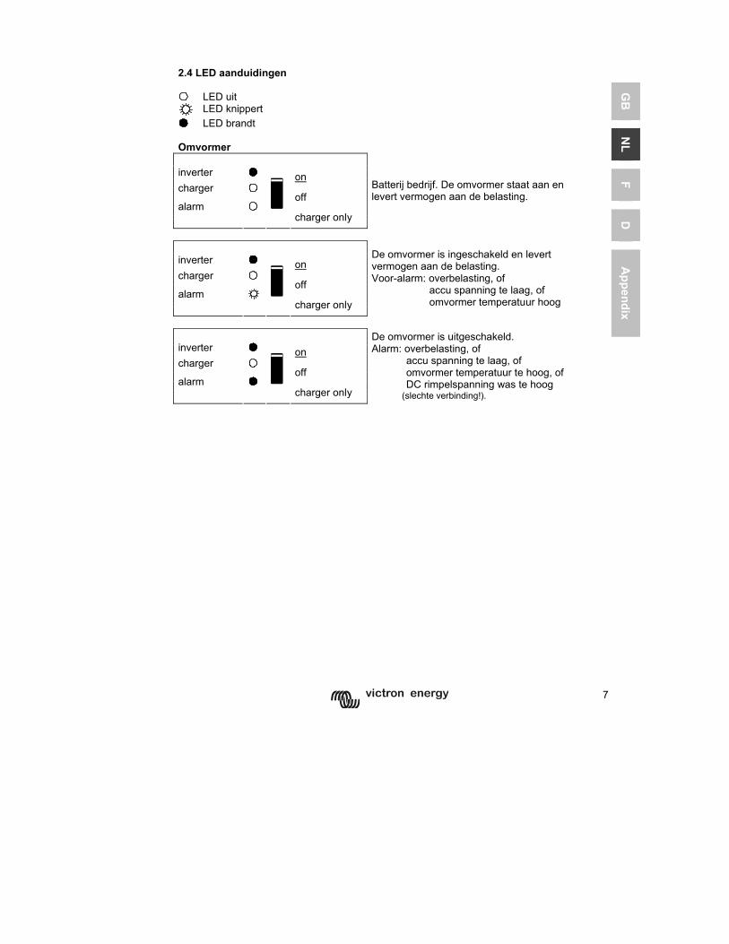
2.4 LED aanduidingen LED uit
LED knippert LED brandt Omvormer inverter on charger off alarm
charger only
Batterij bedrijf. De omvormer staat aan en levert vermogen aan de belasting.
inverter on charger off alarm
charger only
De omvormer is ingeschakeld en levert vermogen aan de belasting. Voor-alarm: overbelasting, of accu spanning te laag, of omvormer temperatuur hoog
inverter on charger off alarm
charger only
De omvormer is uitgeschakeld. Alarm: overbelasting, of accu spanning te laag, of omvormer temperatuur te hoog, of DC rimpelspanning was te hoog (slechte verbinding!).
8
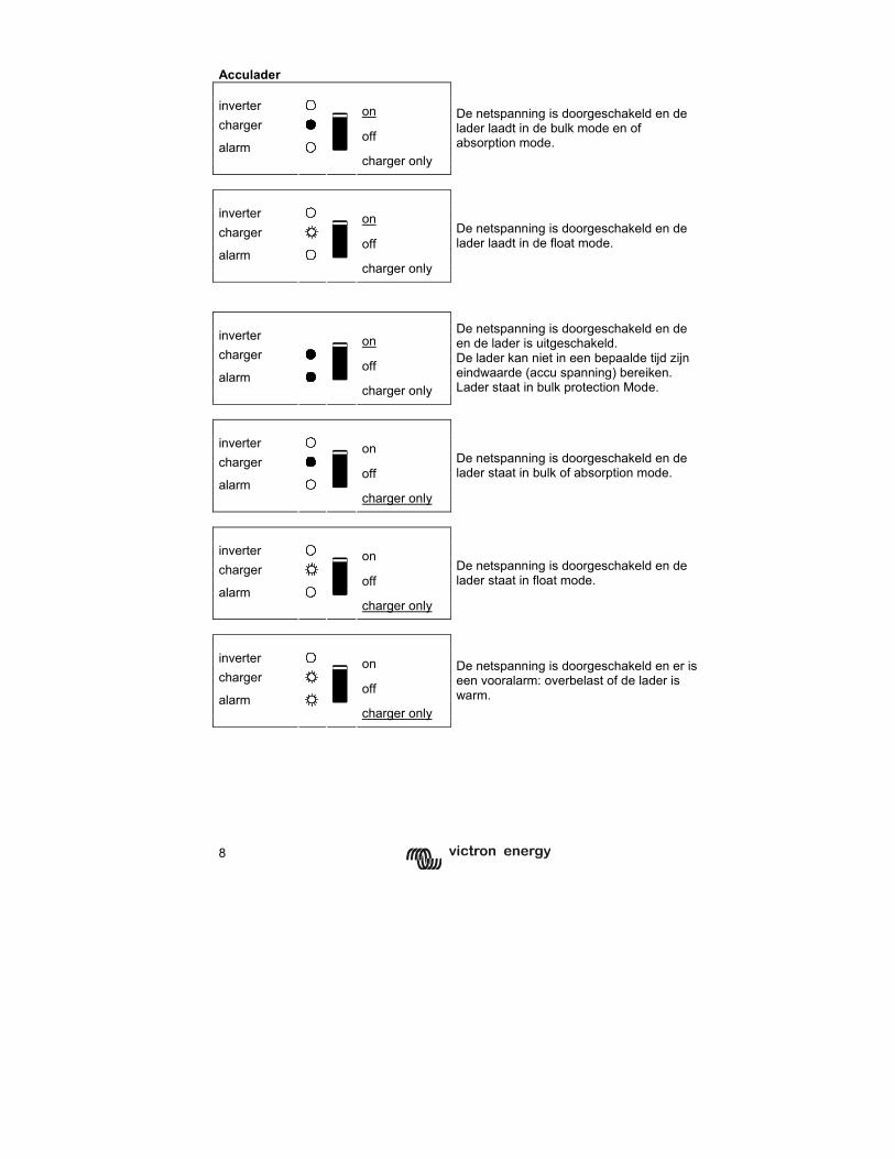
Acculader inverter on charger off alarm
charger only
De netspanning is doorgeschakeld en de lader laadt in de bulk mode en of absorption mode.
inverter on charger off alarm
charger only
De netspanning is doorgeschakeld en de lader laadt in de float mode.
inverter on charger off alarm
charger only
De netspanning is doorgeschakeld en de en de lader is uitgeschakeld. De lader kan niet in een bepaalde tijd zijn eindwaarde (accu spanning) bereiken. Lader staat in bulk protection Mode.
inverter on charger off alarm
charger only
De netspanning is doorgeschakeld en de lader staat in bulk of absorption mode.
inverter on charger off alarm
charger only
De netspanning is doorgeschakeld en de lader staat in float mode.
inverter on charger off alarm
charger only
De netspanning is doorgeschakeld en er is een vooralarm: overbelast of de lader is warm.
9
GB
N
L F
D
Appendix
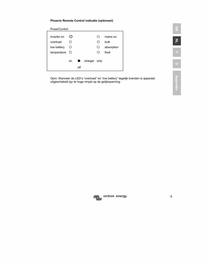
Phoenix Remote Control indicatie (optioneel) PowerControl inverter on mains on overload bulk
low battery absorption
temperature
float
on charger only
off
Opm: Wanneer de LED’s “overload” en “low battery” tegelijk branden is apparaat uitgeschakeld tgv te hoge rimpel op de gelijkspanning.
10
3 INSTALLATIE
Dit product mag alleen door een gekwalificeerde elektrotechnicus worden geïnstalleerd.
3.1 Inhoud van de doos De doos van de Phoenix Multi Compact bevat de volgende zaken: Phoenix Multi Compact Gebruikershandleiding&Installatiehandleiding. Zakje met aansluitmateriaal met daarin: Temperatuursensor. Vijf bevestigingsschroeven. Bevestigingsplaat Waarschuwingssticker laadstroom. 3.2 Locatie De Phoenix Multi Compact dient in een droge, goed geventileerde ruimte te worden geïnstalleerd zo dicht mogelijk bij de accu’s. Rondom het apparaat dient een ruimte van tenminste 50mm te worden vrijgehouden voor koeling.
Een te hoge omgevingstemperatuur heeft de volgende consequenties: Kortere levensduur. Lagere laadstroom. Lager piek vermogen of geheel afschakelen van de omvormer. Plaats het apparaat nooit direct boven de accu’s.
De Phoenix Multi Compact is geschikt voor wandmontage. Voor de montage zijn aan de achterzijde van de behuizing gaten en een beugelbevestiging aangebracht, zie Anhang A. Het apparaat kan zowel horizontaal als verticaal gemonteerd worden maar verticaal monteren is de beste montage. In deze positie is de koeling namelijk optimaal.
De binnenzijde van het apparaat dient ook na installatie goed bereikbaar te blijven.
Zorg ervoor dat de aansluitkabels zijn voorzien van zekeringen en stroomonderbrekers. Houd de afstand tussen de Phoenix Multi Compact en de accu zo kort mogelijk om het spanningsverlies over de kabels tot een minimum te beperken.
In alle apparatuur waarin sprake is van het omvormen van een groot elektrisch vermogen, moet uit voorzorg dit product in een hittebestendige omgeving geïnstalleerd worden. Voorkom daarom de aanwezigheid van bijvoorbeeld chemicaliën, kunststof onderdelen, gordijnen of ander textiel, etc. in de directe omgeving.
Formatted: Bu
Formatted: Bu
Formatted: Bu
Formatted: Bu
11
GB
N
L F
D
Appendix
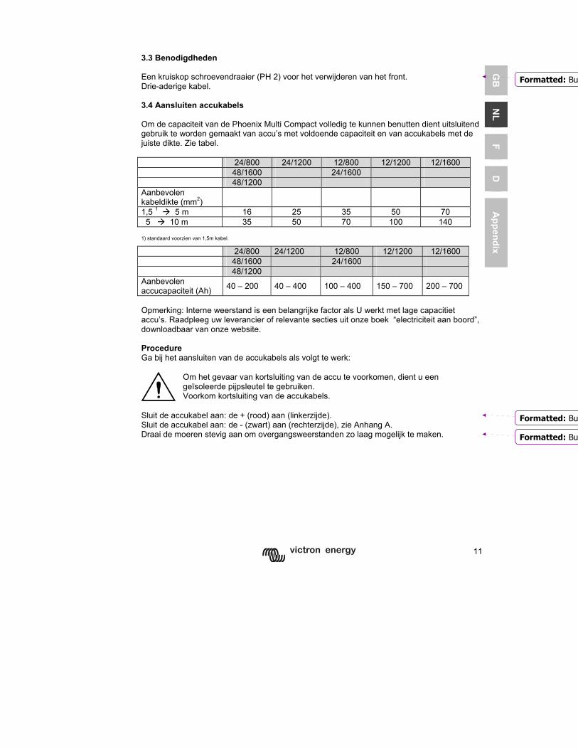
3.3 Benodigdheden Een kruiskop schroevendraaier (PH 2) voor het verwijderen van het front. Drie-aderige kabel. 3.4 Aansluiten accukabels Om de capaciteit van de Phoenix Multi Compact volledig te kunnen benutten dient uitsluitend gebruik te worden gemaakt van accu’s met voldoende capaciteit en van accukabels met de juiste dikte. Zie tabel. 24/800 24/1200 12/800 12/1200 12/1600 48/1600 24/1600 48/1200 Aanbevolen kabeldikte (mm2)
1,5 1 5 m 16 25 35 50 70 5 10 m 35 50 70 100 140
1) standaard voorzien van 1,5m kabel.
24/800 24/1200 12/800 12/1200 12/1600 48/1600 24/1600 48/1200 Aanbevolen accucapaciteit (Ah) 40 – 200 40 – 400 100 – 400 150 – 700 200 – 700
Opmerking: Interne weerstand is een belangrijke factor als U werkt met lage capacitiet accu’s. Raadpleeg uw leverancier of relevante secties uit onze boek “electriciteit aan boord”, downloadbaar van onze website. Procedure Ga bij het aansluiten van de accukabels als volgt te werk:
Om het gevaar van kortsluiting van de accu te voorkomen, dient u een geïsoleerde pijpsleutel te gebruiken. Voorkom kortsluiting van de accukabels.
Sluit de accukabel aan: de + (rood) aan (linkerzijde). Sluit de accukabel aan: de - (zwart) aan (rechterzijde), zie Anhang A. Draai de moeren stevig aan om overgangsweerstanden zo laag mogelijk te maken.
Formatted: Bu
Formatted: Bu
Formatted: Bu
12
3.5 Aansluiten AC kabels
Dit is een product uit veiligheidsklasse I. (dat wordt geleverd met een aardklem ter beveiliging) De in - en/ of uitgangsklemmen en/of het aard punt aan de buitenkant van het product moeten zijn voorzien van een ononderbreekbare aarding ter beveiliging. Zie hiervoor de volgende instructies: a) De Phoenix Inverter Compact heeft een vrij zwevende uitgangspanning. De behuizing moet geaard worden met het aard punt aan de buitenkant van het product. De N uitgang moet geaard worden om verzekerd te zijn van de goede werking van een aardlek schakelaar. b) De Phoenix Multi / MultiPlus Compact: is voorzien van een aard relais (zie Aappedix 2) dat de N uitgang automatisch met de behuizing verbint wanneer geen externe wisselspanning voeding beschikbaar is. Wanneer een externe wisselspanning voeding wordt aangeboden zal het aard relais openen voordat het ingang veiligheids relais sluit (zie appendix 2). Dit is om goede werking van een op de uitgang aangesloten aardlekschakelaar te verzekeren. - In een vaste installatie kan een ononderbreekbare aarding vezekerd worden met de aard draad van de wisselspanning ingang. Zoniet, dan dan moet de behuizing geaard worden. - In een mobiele installatie (bijvoorbeeld met walstroom stekker) zal onderbreking van de walaansluiting tegelijk ook de aard verbinding verbreken. In dat geval moet de behuizing verbonden worden met het chassis (van het voertuig) of met de romp of aardplaat (van de boot). - Op boten is de hierboven beschreven verbinding met de aarde van de walaansluiting i. h. a. niet aan te bevelen i. v. m. galavanische corrosie. De oplossing hiervoor is plaatsing van een isolatie tranformator.
Phoenix Multi Compact is voorzien van in en uitgang connector aan de onderkant van de Multi Compact, zie appendix 1. De wal -of netaansluiting dient met behulp van een drie-aderige kabel op de G-ST18i connector te worden aangesloten. Maak gebruik van een drie-aderige kabel met een soepele kern en een doorsnede van 1,5 mm² (800VA) en 2,5mm²(1600VA). Procedure Ga voor het aansluiten van de AC kabels als volgt te werk: De AC apparatuur kan direct op G-ST18i male-connector worden aangesloten. (eerst de connector los trekken) Gebruik een drie-aderige kabel. De aansluitpunten zijn duidelijk gecodeerd. Van links naar rechts: “N” (nulleider) ,aarde, en “L1” (fase) De AC netspanning kan direct worden aangesloten op de G0st18i female-connector. Gebruik een drie-aderige kabel. De aansluitpunten zijn duidelijk gecodeerd. Van links naar rechts “L1” (fase) ,aarde, “N” (nulleider). Druk de netspannings-connector G-ST18i Female-connector in de contra male-connector (achterste). Druk de belastings-connector G-ST18i male-connector in de contra female-connector (voorste).
Formatted: Bu
Formatted: Bu
13
GB
N
L F
D
Appendix
3.6 Aansluitopties Naast de standaardaansluitingen kunnen er nog een aantal opties worden aangesloten. 3.6.1 Startaccu De Phoenix Multi Compact heeft een aansluiting voor het laden van een startaccu. Zie voor het aansluiten appendix 1.
14
3.6.2 Temperatuursensor (Multi Compact/ MultiPlus Compact) Voor het temperatuur gecompenseerd laden kan de bijgeleverde temperatuursensor worden aangesloten (zie Anhang A). De sensor is geïsoleerd en moet op de min pool van de accu worden gemonteerd. De standaard uitgangsspanningen voor Float en Absorptie zijn 25°C. Reduced Float spanning volgt de Float spanning en Raised Absorptie spanning volgt Absorptie spanning. In de instel mode werkt de temperatuur compensatie niet.
10.010.511.011.512.012.513.013.514.014.515.0
0 5 10 15 20 25 30 35 40 45 50 55 60
Battery temperature
Volts
2021222324252627282930
Volts
3.6.3 Afstandsbediening De Phoenix Multi Compact is op twee manieren op afstand te bedienen. Met alleen een externe schakelaar. Met een “Remote Control ” ofwel afstandsbedieningspaneel. Voor het aansluiten van de schakelaar zie Bijlage A. Indien gebruik wordt gemaakt van alleen een externe schakelaar dient u met het volgende rekening te houden: Werkt alleen als de schakelaar van de Phoenix Multi Compact op “on” staat. Mag niet worden aangesloten als er een afstandsbedieningspaneel is aangesloten. Voor het aansluiten van een afstandsbedieningspaneel zie Bijlage A. Indien gebruik wordt gemaakt van een afstandsbedieningspaneel dient u met het volgende rekening te houden: Werkt alleen als de schakelaar van de Phoenix Multi Compact op “on” staat. 3.6.4 Extern Alarm Relais en Virtual Switch Er is een open collector uitgang beschikbaar waarop en relais aangesloten kan worden tbv alarm en andere signaleringen (o. a. een generator start signaal). De maximum belasting is 66V 40mA. De functie van de open collector uitgang kan geprogrammeerd worden met VEConfigure.
Formatted: Bu
Formatted: Bu
Formatted: Bu
15
GB
N
L F
D
Appendix
4 INSTELLINGEN
Het wijzigen van de instellingen mag alleen worden uitgevoerd door een gekwalificeerde elektrotechnicus. Lees voor het wijzigen goed de instructies. Tijdens het laden moeten accu’s in een droge, goed geventileerde ruimte staan.
4.1 Standaard instellingen Omvormer spanning 230 Vac Lader aan of uit aan = on Laadcurve Adaptive charging, gel accu’s Laadstroom 75% van de nominale laadstroom Absorption spanning 14.4V / 28.8V / 57.6 Vdc Absorption Tijd/ Maximale Absorption tijd 4 uur Float spanning 13.8V / 27.6V / 55.2 Vdc Repeated Absorption Tijd 1 uur Repeated Absorption Interval 7 dagen Bulk Beveiliging on AC Waveform Check on PowerAssist (alleen MultiPlus) on Generator/ Shore Current 12A Systeem frequentie - Multi Compact/ MultiPlus Compact = automatisch
- Inverter Compact = 50 Hz AES (Automatic Economy Switch) off 4.2 Instellingen die met de dipswitches gewijzigd kunnen worden Type Accu Type Absorption spanning Float spanning Maximum
absorption tijd
1 (standaard)
Sonnenschein Dryfit A200 Gel
14.4 V 28.8 V 57.6V 13.8 V/ 13.2V
27.6 V/ 26.4V
55.2V 52.8V
4 uur
2 Tractie (buisjesplaat)
15.0 V 30.0 V 60.0V 13.8 V/ 13.2V
27.6 V/ 26.4V
55.4V 52.8V
6 uur
3 Semi Tractie1
(vlakke plaat) 14.4 V 28.8 V 57.6V 14.0 V/
13.2V 28.0 V/ 26.4V
56V 52.8V
5 uur
4 Alt.1 14.8 V 29.6 V 59.2V 14.0 V/ 13.2V
28.0 V/ 26.4V
56V 52.8V
5 uur
1De optimale absorption spanning van vlakke plaat loodzuur accu’s hang af van mechanische en chemische eigenschappen. Accu's met een hoog antimoon gehalte kunnen in het algemeen geladen worden met een lagere absorption spanning dan accu's met een laag antimoon gehalte. (Zie het boek "Electriciteit aan boord van jachten" op www.victronenergy.com). De lader staat standaard afgeregeld voor het laden van gel accu’s zoals de Sonnenschein Dryfit A200 accu. Vraag bij gebruik van andere Typn accu’s aan uw acculeverancier de juiste laadspanningen en laat zonodig de Phoenix Multi Compact hierop (met behulp van VEConfigure) aanpassen. De Laadstroom staat ingesteld op 75% van nominale laadstroom.Vaak is dit een te hoge laadstroom. De meeste accu’s dienen geladen te worden met een stroom van 0.1 tot 0.2x de capaciteit.
16
Dipswitch instellingen DS-1 off DS-2 DS-3 DS-4 DS-5 DS-6 DS-7 DS-8
DS-1 off DS-2 ← onDS-3 DS-4 DS-5 DS-6 DS-7 DS-8
DS1=off
Bij gebruik van: Remote Control DS-2 = off
DS-1 wordt niet gebruikt moet altijd op Off staan. Accu laad curve DS-1 off DS-2 on DS-3 off DS-4 off DS-5 DS-6 DS-7 DS-8
DS-1 off DS-2 onDS-3 x x DS-4 x x DS-5 DS-6 DS-7 DS-8
DS3=off,DS4=off = Typ 1 (gel) DS3=on,DS4=off = Typ 2 DS3=off,DS4=on = Typ 3 DS3=on,DS4=on = Typ 4
Opslaan: druk schakelaar DS-8 naar on en weer terug naar off. De instelling van DS3-DS4 is nu actief.
17
GB
N
L F
D
Appendix
Omvormer frequentie DS-1 off DS-2 on DS-3 DS-4 DS-5 off DS-6 DS-7 DS-8
DS-1 off DS-2 onDS-3 DS-4 DS-5 x x DS-6 DS-7 DS-8
DS5=off = 50Hz DS5=on = 60Hz
Opslaan: druk schakelaar DS-8 naar on en weer terug naar off. De instelling van DS5 is nu actief.
AES (Automatic Economy Switch) DS-1 off DS-2 on DS-3 DS-4 DS-5 DS-6 off DS-7 DS-8
DS-1 off DS-2 onDS-3 DS-4 DS-5 DS-6 x x DS-7 DS-8
DS6=off = normaal DS6=on = economy
Opslaan: druk schakelaar DS-8 naar on en weer terug naar off.De instelling van DS6 is nu actief.
Generator/ Walstroom DS-1 off DS-2 on DS-3 DS-4 DS-5 DS-6 DS-7 off DS-8
DS-1 off DS-2 onDS-3 DS-4 DS-5 DS-6 DS-7 x x DS-8
DS7=off = MainsLimit 16 Amp DS7=on = MainsLimit 6 Amp
Opslaan: druk schakelaar DS-8 naar on en weer terug naar off. De instelling van DS7 is nu actief.
18
4.3 De “adaptive charging” laad curve
64 32
60 30 56 28
52 26
48 24
44 22 40 20
C h a rg e c u rre n t
0%
20%
40%
60%
80%
100%
120%
T im e
A m p s
C h a rg e v o lta g e
10
11
12
13
14
15
16
T im e
V o lts
4-laad karakteristieken:
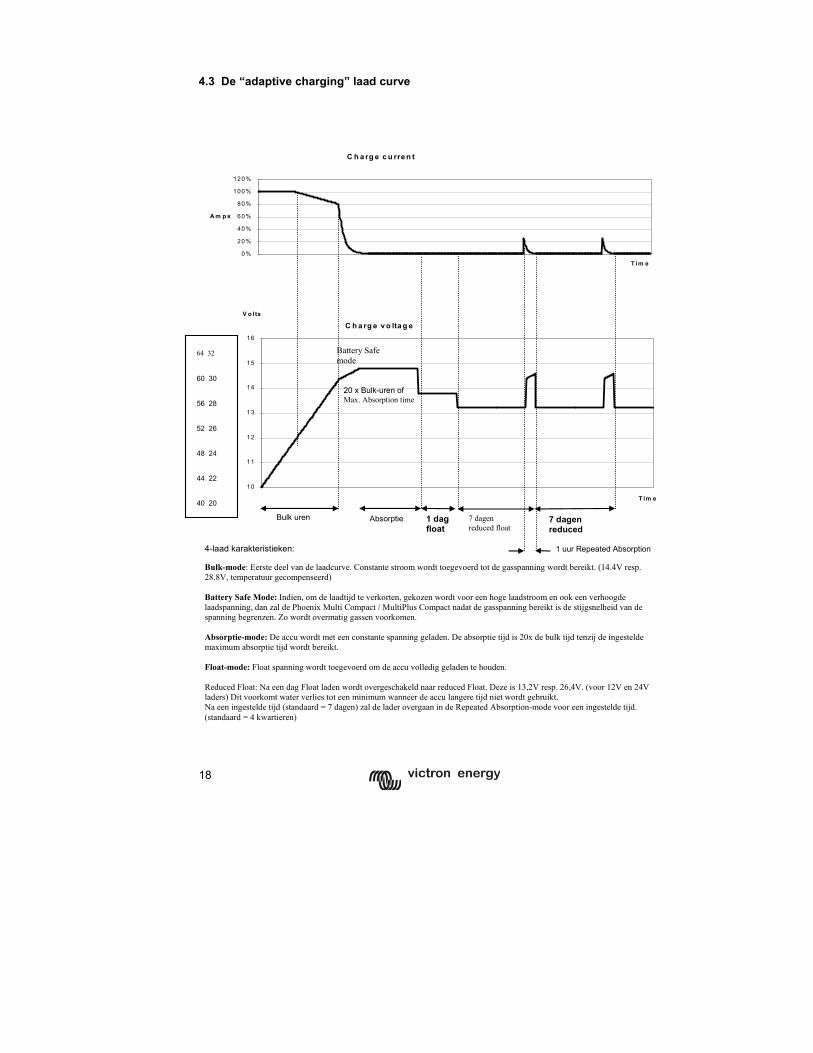
Bulk-mode: Eerste deel van de laadcurve. Constante stroom wordt toegevoerd tot de gasspanning wordt bereikt. (14.4V resp. 28.8V, temperatuur gecompenseerd) Battery Safe Mode: Indien, om de laadtijd te verkorten, gekozen wordt voor een hoge laadstroom en ook een verhoogde laadspanning, dan zal de Phoenix Multi Compact / MultiPlus Compact nadat de gasspanning bereikt is de stijgsnelheid van de spanning begrenzen. Zo wordt overmatig gassen voorkomen. Absorptie-mode: De accu wordt met een constante spanning geladen. De absorptie tijd is 20x de bulk tijd tenzij de ingestelde maximum absorptie tijd wordt bereikt. Float-mode: Float spanning wordt toegevoerd om de accu volledig geladen te houden. Reduced Float: Na een dag Float laden wordt overgeschakeld naar reduced Float. Deze is 13,2V resp. 26,4V. (voor 12V en 24V laders) Dit voorkomt water verlies tot een minimum wanneer de accu langere tijd niet wordt gebruikt. Na een ingestelde tijd (standaard = 7 dagen) zal de lader overgaan in de Repeated Absorption-mode voor een ingestelde tijd. (standaard = 4 kwartieren)
Bulk uren 1 dagfloat
7 dagen reduced float
Absorptie
1 uur Repeated Absorption
7 dagen reduced
20 x Bulk-uren of Max. Absorption time
Battery Safe mode
64 32 60 30 56 28 52 26 48 24 44 22 40 20
19
GB
N
L F
D
Appendix
4.4 Instelling lader (alleen Multi Compact / MultiPlus Compact) De nu volgende instellingen kunnen alleen gewijzigd worden met VEConfigure software Lader aan/ uit (standaard: aan) De lader van de Phoenix Multi Compact kan desgewenst ook uitgeschakeld worden. 4.4.1 De 3 voorgeprogrameerde laadcurves: De Fixed laadkarakteristiek biedt de absorption spanning voor een bepaalde (vast instelbare) tijd aan. Na de absorptionfase wordt een bepaalde (wederom vast instelbare) tijd de floatspanning aangeboden, om daarna periodiek gedurende een (meestal kortere) tijd weer de absorptionspanning aan te bieden. De Adaptieve laadkarakteristiek biedt de absorptionspanning aan gedurende een tijd afhankelijk van de lading die tijdens bulk is geleverd. Daarna volgt een floatfase van 24 uur, waarna naar 13/ 26V (gereduceerd float) wordt teruggeschakeld. Net als bij de Fixed laadkarakteristiek wordt ook hier periodiek een absorptionfase aangehouden. Adaptieve laadkarakteristiek met BatterySafe mode (standaard instelling) Indien, om de laadtijd te verkorten, gekozen wordt voor een hoge laadstroom en ook een verhoogde laadspanning, dan zal de Phoenix Multi Compact / MultiPlus Compact nadat de gasspanning bereikt is de stijgsnelheid van de spanning begrenzen. Zo wordt overmatig gassen voorkomen. 4.4.2 Overige lader instellingen: De laadstroom is standaard ingesteld op 75% van de maximale laadstroom. Voor veel toepassingen zal deze stroom te hoog zijn. Om te voorkomen dat de accu’s defect raken is het noodzakelijk om de laadstroom aan te passen naar 0,1-0,2x de accucapaciteit. De stapgrootte is 1A. Absorptionspanning (standaard 14.4V / 28.8V) De absorptionspanning is in te stellen van 12-16/ 24-32V. De stapgrootte is 0,05 V Absorptiontijd/ maximale absorptiontijd (standaard 4 uur) Deze instelling bepaalt bij de fixed laadkarakteristiek hoelang de lader de absorptionspanning aanbiedt. Bij de adaptieve laadkarakteristiek bepaalt deze instelling wat de maximale tijd is dat de lader de absorptionspanning aanbiedt. De (maximale) absorptiontijd kan worden ingesteld van 1 tot 8 uur. De stapgrootte is 1 uur. Floatspanning De floatspanning is in te stellen van 12-16/ 24-32V De stapgrootte is 0,05 V. Herhaalde absorptiontijd (standaard 1 uur) De herhaalde absorptiontijd kan worden ingesteld van 1 tot 72 kwartier. De stapgrootte is 1 kwartier Herhaald absorptioninterval (standaard 7 dagen) Het herhaald absorptioninterval, kan worden ingesteld van 1 tot 45 dagen. De stapgrootte is 1 dag.
20
4.5 Bijzondere instellingen (alleen instelbaar met VEConfigure software) Bulkbescherming aan/ uit (standaard: aan) Als de lader na 10 uur in de bulkfase te hebben geladen de absorption spanning nog niet heeft bereikt kan het zijn dat de accu defect is. Om verdere schade te voorkomen zal de lader na 10 uur bulk automatisch worden uitgeschakeld. De rode LED ”alarm” gaat dan branden. AC Waveform Check (standaard: aan) De Phoenix Multi Compact controleert of the netspanning niet alleen de juiste voltage heeft, maar ook de juiste sinus vorm. Indien de Phoenix Multi Compact niet goed functioneert op een generator kan deze functie worden uitgeschakeld. PowerContol: omgaan met beperkte generator/ walstroom Ter bescherming van de generator of van de walstroomaansluiting wordt de laadstroom zodanig ingesteld dat de gezamenlijk afgenomen stroom door de lader en de AC verbruikers niet boven de ingestelde stroom komt. Als het AC verbruik boven de ingestelde stroom komt, zal de lader uitschakelen en de “mains on” LED gaan knipperen. Het is nu mogelijk dat de walzekering doorslaat of de generator door overbelasting uitschakelt. In dat geval zal de Multi Compact proberen om te schakelen naar omvormerbedrijf. De generator/ walstroom kan worden ingesteld van 2 tot 16A. De stapgrootte is 1A. Bij gebruik van het Remote Control paneel wordt de walstroom instelling bepaald door dit paneel. Wanneer de aan de Phoenix Multi Compact aangeboden spanningsvorm niet zuiver sinusvorming is, bestaat de kans dat de Phoenix Multi Compact deze niet zal accepteren. U kunt deze detectie uitschakelen door de shore current limiter naar “0” te draaien. PowerAssist – Doe meer met Uw aggregaat of walstroom: de unieke “meehelp” functie van de MultiPlus Compact (standaard: aan) Met de MultiPlus Compact kunt U nog een stap verder gaan. De MultiPlus Compact werkt parallel met het aggregaat of de walaansluiting en verdubbelt het beschikbare vermogen. Tijdelijk te weinig stroom? De MultiPlus Compact haalt extra energie uit de accu en helpt mee! Nog stroom over? De MultiPlus Compact maakt er gebruik van om de accu te laden. U stelt de walstroom in met een simpele 0 tot 16 A draaiknop op het Phoenix Multi Control paneel. Noot 1: Voor de goede werking van PowerAssist dient minstens 2A netvoeding of een aggregaat met ten minste hetzelfde vermogen als de MultiPlus beschikbaar te zijn. Noot 2: Sommige moderne generatoren generen de wisselstroom m. b. v. een statische omvormer. Het toerental van deze generatoren wordt meestal teruggeregeld bij geringe belasting. Indien met VEConfigure de “Dynamic Current Limit”functie aangezet wordt zal de MultiPlus een plotselinge belastingsprong opvangen totdat de motor van het aggregaat weer op volle toeren draait.
21
GB
N
L F
D
Appendix
Extern Alarm Relais en Virtual Switch (standaard: uitgeschakeld) Er is een open collector uitgang beschikbaar waarop en relais aangesloten kan worden tbv alarm en andere signaleringen (o. a. een generator start signaal). De maximum belasting is 66V 40mA. De functie van de open collector uitgang kan geprogrammeerd worden met VEConfigure. 4.6 Onderhoud De Phoenix Multi Compact vereist geen specifiek onderhoud. Het volstaat alle verbindingen eenmaal per jaar te controleren. Voorkom dat de Phoenix Multi Compact vochtig wordt en houd het apparaat schoon.
22
5 FOUTZOEKSCHEMA
Met behulp van onderstaande stappen kunnen de meest voorkomende storingen snel worden opgespoord. Voordat testen met de omvormer en/ of acculader worden uitgevoerd dienen de DC-belastingen te worden losgekoppeld van de accu’s en de AC-apparatuur dient te worden losgekoppeld van de omvormer. Indien de fout niet opgelost kan worden, raadpleeg uw Victron Energy distributeur.
Probleem Oorzaak Oplossing De omvormer werkt niet wanneer deze wordt ingeschakeld
De accuspanning is te hoog of te laag.
Zorg dat de accuspanning binnen de juiste waarde is.
De omvormer werkt niet
Processor staat in uit-mode Ontkoppel de netspanning. Schakel de omvormer uit. Wacht 4 seconden. Schakel de omvormer weer aan.
De LED “alarm” knippert.
Voor-alarm, alt. 1: de accuspanning is laag.
Laad de accu op of controleer de accu aansluitingen.
De LED “alarm” knippert.
Voor-alarm, alt. 2: de belasting op de omvormer is hoger dan de nominale belasting.
Ontkoppel een deel van de belasting.
De LED “alarm” knippert.
Voor-alarm, alt. 3: lage accuspanning en te hoge belasting.
Laad de accu’s op, ontkoppel een deel van de belasting of plaats accu’s met een hogere capaciteit. Monteer kortere en/ of dikkere accukabels. Controleer de dynamo.
De LED “alarm” knippert.
Voor-alarm, alt. 3: rimpelspanning op de DC-aansluiting overschrijdt 1,25Vrms.
Controleer de accukabels en accuaansluitingen. Wees er zeker van dat de accucapaciteit voldoende is, verhoog deze eventueel.
De LED “lalarm” brandt.
De omvormer is uitgeschakeld als gevolg van voortduring van een van bovenstaande voor-alarm omstandigheden.
Zie de bovenstaande oplossingen
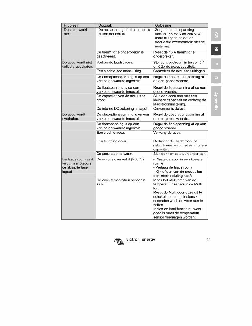
23
GB
N
L F
D
Appendix
Probleem Oorzaak Oplossing
De netspanning of –frequentie is buiten het bereik.
Zorg dat de netspanning tussen 185 VAC en 265 VAC komt te liggen en dat de frequentie overeenkomt met de instelling.
De lader werkt niet
De thermische onderbreker is geactiveerd.
Reset de 16 A thermische onderbreker.
De accu wordt niet volledig opgeladen.
Verkeerde laadstroom. Stel de laadstroom in tussen 0,1 en 0,2x de accucapaciteit.
Een slechte accuaansluiting. Controleer de accuaansluitingen.
De absorptionspanning is op een verkeerde waarde ingesteld.
Regel de absorptionspanning af op een goede waarde.
De floatspanning is op een verkeerde waarde ingesteld.
Regel de floatspanning af op een goede waarde.
De capaciteit van de accu is te groot.
Sluit een accu aan met een kleinere capaciteit en verhoog de laadstroominstelling.
De interne DC zekering is kapot. Omvormer is defect. De accu wordt overladen.
De absorptionspanning is op een verkeerde waarde ingesteld.
Regel de absorptionspanning af op een goede waarde.
De floatspanning is op een verkeerde waarde ingesteld.
Regel de floatspanning af op een goede waarde.
Een slechte accu. Vervang de accu.
Een te kleine accu. Reduceer de laadstroom of gebruik een accu met een hogere capaciteit.
De accu staat te warm. Sluit een temperatuursensor aan.De laadstroom zakt terug naar 0 zodra de absrptie fase ingaat
De accu is oververhit (>50°C) - Plaats de accu in een koelere ruimte - Verlaag de laadstroom - Kijk of een van de accucellen een interne sluitng heeft
De accu temperatuur sensor is stuk
Maak het stekkertje van de temperatuur sensor in de Multi los. Reset de Multi door deze uit te schakelen en na minstens 4 seconden wachten weer aan te zetten. Indien de laad functie nu weer goed is moet de temperatuur sensor vervangen worden.
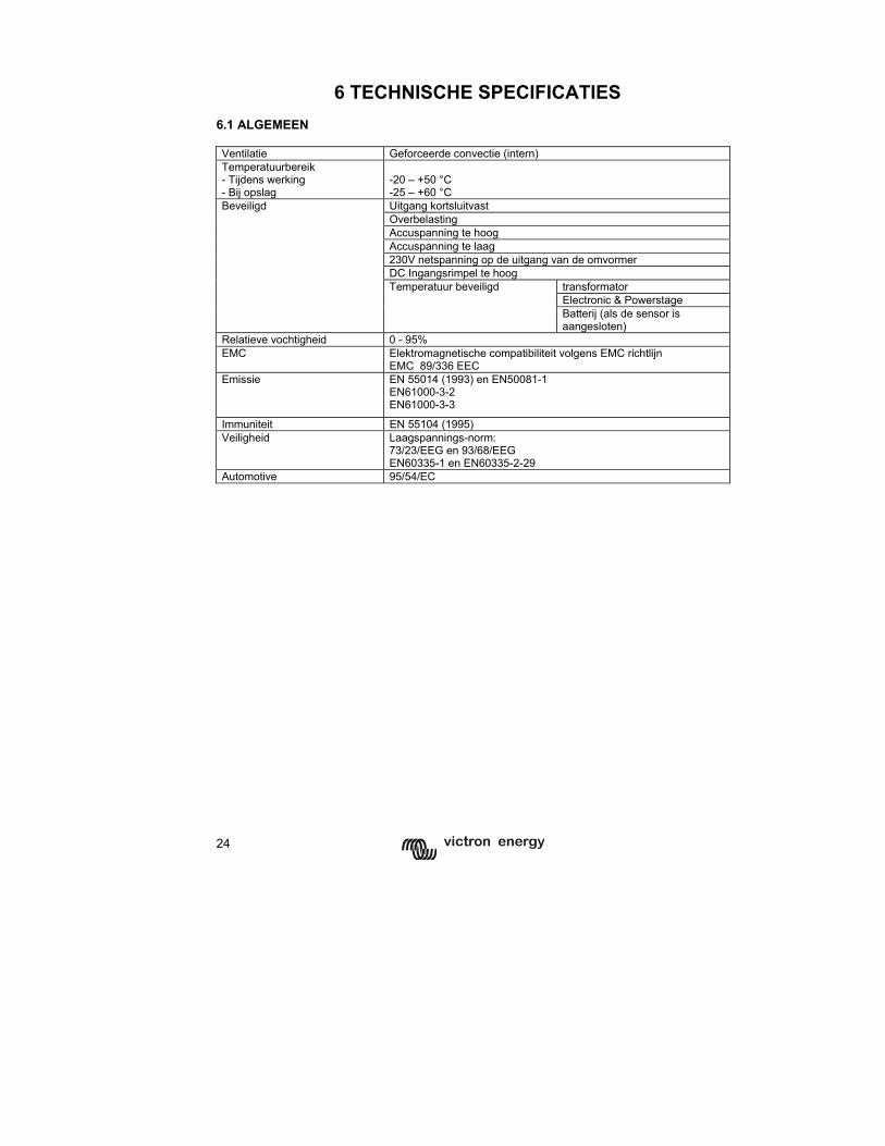
24
6 TECHNISCHE SPECIFICATIES
6.1 ALGEMEEN Ventilatie Geforceerde convectie (intern) Temperatuurbereik - Tijdens werking - Bij opslag
-20 – +50 °C -25 – +60 °C Uitgang kortsluitvast Overbelasting Accuspanning te hoog Accuspanning te laag 230V netspanning op de uitgang van de omvormer DC Ingangsrimpel te hoog
transformator Electronic & Powerstage
Beveiligd
Temperatuur beveiligd
Batterij (als de sensor is aangesloten)
Relatieve vochtigheid 0 - 95% EMC Elektromagnetische compatibiliteit volgens EMC richtlijn
EMC 89/336 EEC Emissie EN 55014 (1993) en EN50081-1
EN61000-3-2 EN61000-3-3
Immuniteit EN 55104 (1995) Veiligheid Laagspannings-norm:
73/23/EEG en 93/68/EEG EN60335-1 en EN60335-2-29
Automotive 95/54/EC
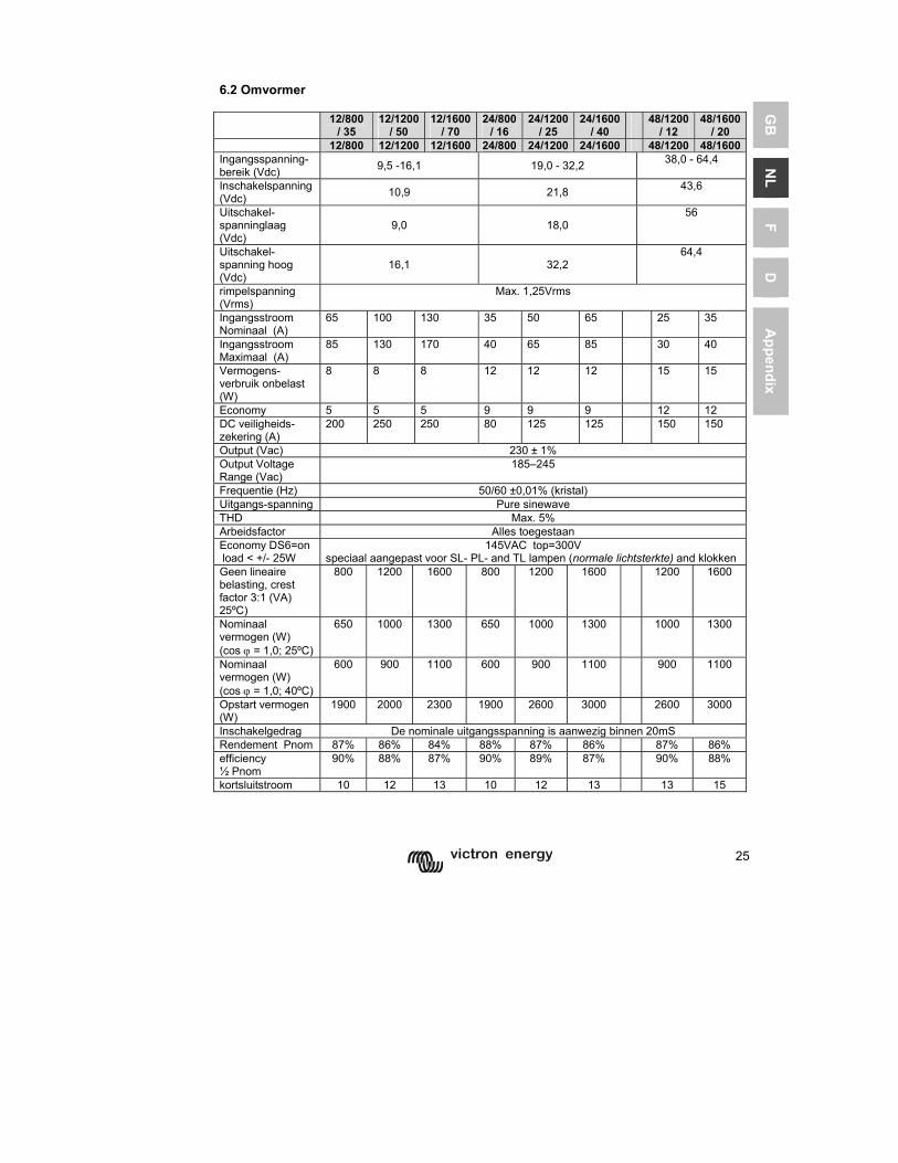
25
GB
N
L F
D
Appendix
6.2 Omvormer 12/800
/ 35 12/1200
/ 50 12/1600
/ 70 24/800
/ 16 24/1200
/ 25 24/1600
/ 40
48/1200 / 12
48/1600/ 20
12/800 12/1200 12/1600 24/800 24/1200 24/1600 48/1200 48/1600Ingangsspanning-bereik (Vdc) 9,5 -16,1 19,0 - 32,2 38,0 - 64,4
Inschakelspanning (Vdc) 10,9 21,8 43,6
Uitschakel-spanninglaag (Vdc)
9,0 18,0 56
Uitschakel-spanning hoog (Vdc)
16,1 32,2 64,4
rimpelspanning (Vrms)
Max. 1,25Vrms
Ingangsstroom Nominaal (A)
65 100 130 35 50 65 25 35
Ingangsstroom Maximaal (A)
85 130 170 40 65 85 30 40
Vermogens-verbruik onbelast (W)
8 8 8 12 12 12 15 15
Economy 5 5 5 9 9 9 12 12 DC veiligheids- zekering (A)
200 250 250 80 125 125 150 150
Output (Vac) 230 ± 1% Output Voltage Range (Vac)
185–245
Frequentie (Hz) 50/60 ±0,01% (kristal) Uitgangs-spanning Pure sinewave THD Max. 5% Arbeidsfactor Alles toegestaan Economy DS6=on load < +/- 25W
145VAC top=300V speciaal aangepast voor SL- PL- and TL lampen (normale lichtsterkte) and klokken
Geen lineaire belasting, crest factor 3:1 (VA) 25ºC)
800 1200 1600 800 1200 1600 1200 1600
Nominaal vermogen (W) (cos ϕ = 1,0; 25ºC)
650 1000 1300 650 1000 1300 1000 1300
Nominaal vermogen (W) (cos ϕ = 1,0; 40ºC)
600 900 1100 600 900 1100 900 1100
Opstart vermogen (W)
1900 2000 2300 1900 2600 3000 2600 3000
Inschakelgedrag De nominale uitgangsspanning is aanwezig binnen 20mS Rendement Pnom 87% 86% 84% 88% 87% 86% 87% 86% efficiency ½ Pnom
90% 88% 87% 90% 89% 87% 90% 88%
kortsluitstroom 10 12 13 10 12 13 13 15
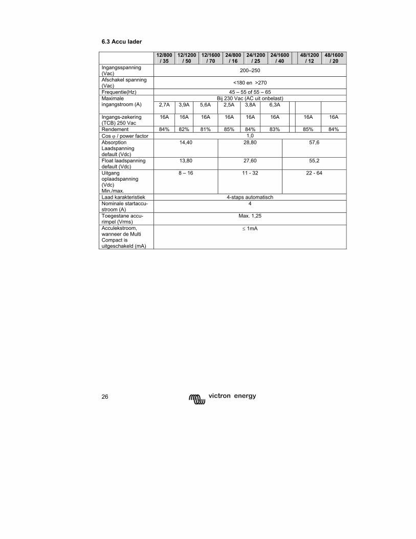
26
6.3 Accu lader 12/800
/ 35 12/1200
/ 50 12/1600
/ 70 24/800
/ 16 24/1200
/ 25 24/1600
/ 40
48/1200 / 12
48/1600/ 20
Ingangsspanning (Vac) 200–250
Afschakel spanning (Vac) <180 en >270
Frequentie(Hz) 45 – 55 of 55 – 65 Bij 230 Vac (AC uit onbelast) Maximale
ingangstroom (A) 2,7A 3,9A 5,6A
2,5A 3,8A 6,3A
Ingangs-zekering (TCB) 250 Vac
16A 16A 16A 16A 16A 16A 16A 16A
Rendement 84% 82% 81% 85% 84% 83% 85% 84% Cos ϕ / power factor 1,0 Absorption Laadspanning default (Vdc)
14,40 28,80 57,6
Float laadspanning default (Vdc)
13,80 27,60 55,2
Uitgang oplaadspanning (Vdc) Min./max.
8 – 16 11 - 32 22 - 64
Laad karakteristiek 4-staps automatisch Nominale startaccu-stroom (A)
4
Toegestane accu-rimpel (Vrms)
Max. 1,25
Acculekstroom, wanneer de Multi Compact is uitgeschakeld (mA)
≤ 1mA
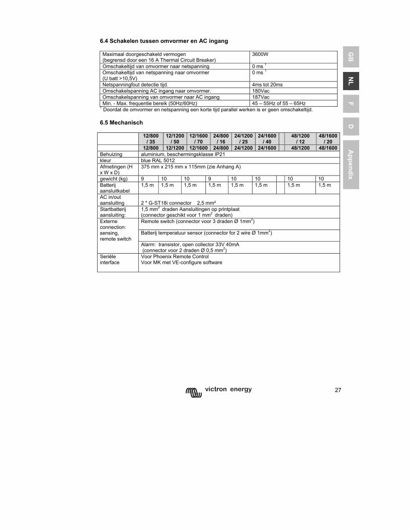
27
GB
N
L F
D
Appendix
6.4 Schakelen tussen omvormer en AC ingang Maximaal doorgeschakeld vermogen (begrensd door een 16 A Thermal Circuit Breaker)
3600W
Omschakeltijd van omvormer naar netspanning 0 ms 1 Omschakeltijd van netspanning naar omvormer (U batt >10,5V)
0 ms 1
Netspanningfout detectie tijd. 4ms tot 20ms Omschakelspanning AC ingang naar omvormer. 180Vac Omschakelspanning van omvormer naar AC ingang 187Vac Min. - Max. frequentie bereik (50Hz/60Hz) 45 – 55Hz of 55 – 65Hz
1 Doordat de omvormer en netspanning een korte tijd parallel werken is er geen omschakeltijd. 6.5 Mechanisch 12/800
/ 35 12/1200
/ 50 12/1600
/ 70 24/800
/ 16 24/1200
/ 25 24/1600
/ 40 48/1200
/ 12 48/1600
/ 20 12/800 12/1200 12/1600 24/800 24/1200 24/1600 48/1200 48/1600Behuizing aluminium, beschermingsklasse IP21 kleur blue RAL 5012 Afmetingen (H x W x D)
375 mm x 215 mm x 115mm (zie Anhang A)
gewicht (kg) 9 10 10 9 10 10 10 10 Batterij aansluitkabel
1,5 m 1,5 m 1,5 m 1,5 m 1,5 m 1,5 m 1,5 m 1,5 m
AC in/out aansluiting
2 * G-ST18i connector 2,5 mm²
Startbatterij aansluiting:
1,5 mm2 draden Aansluitingen op printplaat (connector geschikt voor 1 mm2 draden) Remote switch (connector voor 3 draden Ø 1mm2)
Batterij temperatuur sensor (connector for 2 wire Ø 1mm2)
Externe connection: sensing, remote switch
Alarm: transistor, open collector 33V 40mA (connector voor 2 draden Ø 0,5 mm2)
Seriële interface
Voor Phoenix Remote Control Voor MK met VE-configure software

28
1
GB
N
L F
D
Appendix
CONSIGNES DE SECURITE Généralités Lisez toute la documentation fournie avec l'appareil afin de vous familiariser avec les règles de sécurité avant toute utilisation. Ce produit a été conçu et testé selon les normes internationales. Cet appareil ne doit être utilisé que pour l'application à laquelle il est destiné. ATTENTION : DANGER DE CHOC ELECTRIQUE. L'appareil est utilisé conjointement avec une source d'énergie permanente (batterie). Même lorsque l'appareil est hors tension, une tension dangereuse peut être présente sur les bornes d'entrée et de sortie. Toujours débrancher l'alimentation de courant alternatif et la batterie avant toute manipulation d'entretien. Cet appareil ne comprend aucun élément interne pouvant être réparé ou entretenu par l'utilisateur. Ne jamais retirer le panneau frontal et ne jamais mettre l'appareil en service si tous les panneaux ne sont pas montés. Tout entretien doit être effectué par un personnel qualifié. Ne jamais utiliser l'appareil là où des explosions de gaz ou de poussière peuvent se produire. Consulter les indications du fabriquant des batteries pour vous assurer de la compatibilité des batteries avec l'appareil. Les consignes de sécurité du fabriquant des batteries doivent toujours être respectées. ATTENTION : Ne jamais soulever de charges lourdes sans aide. Installation Lisez attentivement les consignes d'installation avant de mettre l'appareil en service. Ce produit est classé dans la classe de sécurité I (livré avec prise mise à la terre). Une mise à la terre permanente doit être réalisée sur les bornes d'entrée et/ou de sortie du courant alternatif, ou sur la borne de mise à la terre externe. Si vous suspectez la protection par prise de terre d'être endommagée, l'appareil doit être mis hors tension et protégé contre toute mise en service involontaire. Adressez-vous à une personne qualifiée. Assurez-vous que tous les câbles de raccordement sont équipés de fusibles et disjoncteurs. Ne jamais remplacer les protections par d'autres d'un Typ différent. Consultez les manuels pour utiliser protections appropriées. Avant de mettre l'appareil en service, contrôlez que la source de courant corresponde à la configuration de l'appareil tel que décrite dans le manuel. Assurez-vous que l'appareil est utilisé dans les conditions ambiantes correctes. Ne jamais utiliser l'appareil dans un environnement humide ou poussiéreux. Conservez toujours suffisamment d'espace libre autour de l'appareil pour la ventilation et assurez-vous que les orifices de ventilation ne sont pas obstrués. Assurez-vous que la puissance souhaitée ne soit pas supérieure à la capacité de l'appareil. Transport et stockage Assurez-vous que les câbles de secteur et de batterie sont déconnectés pour le transport et le stockage. Aucune responsabilité ne sera acceptée pour dommages de transport si l'appareil est transporté dans un autre emballage que celui d'origine. Stockez l'appareil dans un endroit sec ; la température de stockage doit être comprise entre –20°C et +60°C. Consultez le mode d'emploi des batteries en ce qui concerne le transport, le stockage, la charge et la mise au rebut des batteries.
2
1 DESCRIPTION
1.1 Généralités Multifonctions (Multi / MultiPlus Compact uniquement) Le Multi Compact doit son nom aux nombreuses fonctions qu'il assure : il rassemble un convertisseur sinusoïdal puissant, un chargeur sophistiqué à technologie de charge adaptative et un commutateur de transfert ultra rapide. En plus de ces fonctions de base le Multi Compact offre de nombreuses caractéristiques avancées décrites ci-dessous, qui ouvrent la voie vers des applications nouvelles. Alimentation AC ininterrompue (Multi Compact/ MultiPlus Compact seulement) En cas de coupure secteur ou de déconnexion du quai ou du groupe, le convertisseur du Multi Compact reprend automatiquement l'alimentation du réseau en sortie. Ce transfert est si rapide (moins de 20 millisecondes) que le fonctionnement d’ordinateurs ou d’autres équipements électroniques sensibles raccordés ne seront pas perturbés. PowerControl – La parade aux puissances limitées du quai ou d'un groupe (Multi Compact/ MultiPlus Compact seulement) Le Multi Compact comporte un chargeur de batterie très puissant qui demande de fortes intensités aux branchements à quai (près de 5 A en 230 Vac par Multi Compact). Le tableau de commande Phoenix Multi Control (PMV) permet de limiter la puissance à fournir par le quai. Le Multi Compact prend alors en compte la demande de puissance AC en sortie et n'utilisera que l'excédent pour la charge, évitant ainsi toute surcharge du quai ou d'un groupe électrogène. PowerAssist – Davantage de puissance que le quai ou le groupe PowerAssist est une fonction supplémentaire qui distingue le MultiPlus Compact du Multi Compact. Le MultiPlus travaille en parallèle avec la source d’alimentation (groupe électrogène, prise de quai…) et permet de doubler la puissance disponible : lorsque la limite fixée (voir PowerControl) est dépassée le convertisseur du MultiPlus fournit le complément à partir de la batterie. Il est ainsi possible de faire face à des surcharges momentanées. Toute puissance excédentaire disponible en entrée est automatiquement utilisée pour la (re)charge de la batterie. Note 1: The rating of the generator should be 75% or higher compared to the VA rating of the MultiPlus Compact. (for ex: a genset of at least 900 VA will be required to operate in parallel with a Multi Compact 12/1200/50. Note 2: The output waveform of a generator can be heavily distorted. In that case the “AC waveform check” should be disabled. See page 20.
3
GB
N
L F
D
Appendix
1.2 Chargeur de batteries (Multi / MultiPlus Compact uniquement) Caractéristique de charge adaptative en 4 étapes : Bulk – Absorption – Float – Veille Le Multi / MultiPlus Compact innove par son système de gestion de charge 'adaptative' pilotée par microprocesseur et paramétrable selon les différents Typs de batteries. La fonction 'adaptative' optimise automatiquement le processus de charge à l'utilisation faite de la batterie. La bonne dose de charge : durée d'absorption variable Lorsque la batterie est peu sollicitée (par exemple sur un bateau raccordé au quai) la phase de charge d'absorption est raccourcie pour éviter toute surcharge. Après une décharge profonde la durée de la charge d'absorption est automatiquement allongée pour assurer une recharge complète de la batterie. Prévention des détériorations dues au gazage : progression limitée de la tension Si pour obtenir une recharge rapide un courant élevé a été associé à une tension d'absorption élevée, le Multi / MultiPlus Compact évite une détérioration due au gazage en limitant automatiquement la progression de la tension dès que la tension de gazage est atteinte. Moins d'entretien et de vieillissement quand la batterie ne sert pas : le mode Veille Le mode veille intervient lorsque la batterie n'a pas été sollicitée pendant 24 heures. En mode veille la tension Float est ramenée à 2,2V/élément (13,2V pour une batterie 12V) pour minimiser le gazage et la corrosion des plaques positives. Ensuite la tension est relevée au niveau d'absorption une heure par semaine pour 'égaliser' la batterie. Ce procédé empêche la stratification de l'électrolyte et la sulfatation, causes majeures de vieillissement prématuré d'une batterie. Deux sorties pour charger 2 (bancs de) batteries Le Multi / MultiPlus Compact est équipé de 2 sorties isolées, dont une peut fournir la puissance totale. La seconde sortie destinée à l'entretien d'une batterie auxiliaire (démarrage) est limitée à environ 4 ampères sous une tension légèrement plus basse. Pour une meilleure longévité de la batterie : compensation en température Le Multi / MultiPlus Compact est livré avec une sonde de température de batterie qui fera automatiquement diminuer la tension de charge lorsque la température de la batterie augmente. Cette fonction est particulièrement importante pour des batteries étanches ou lorsque des variations de température importantes peuvent se produire. Sonde de tension batterie Pour améliorer encore la qualité de le Multi / MultiPlus Compact, la possibilité de mesure directe de la tension aux bornes de la batterie permet au chargeur de compenser les pertes de tension dans le câblage principal. Pour tout savoir sur les batteries Notre livre 'L'Electricité à Bord' traite en détail des différents Typs de batterie et des techniques de charge. (Distribué gratuitement et téléchargeable sur notre site www.victronenergy.com). Pour plus de détails sur la technologie de charge adaptative, voir la rubrique infos techniques sur notre site.
4
1.3 Liste et références des accessoires disponibles en option Tableau Phoenix Multi control REC020002000 Tableau Phoenix Inverter control REC030001000 Sonde de température TI ASS000001000 Cordon UTP Patch lead 5 m ASS030065000 Cordon UTP Patch lead 10 m ASS030065010 Cordon UTP Patch lead 15 m ASS030065020 Interface pour PC MK1.b ASS0301B0000 Adaptateur USB ASS030200000 VEConfigure programme de paramétrage Téléchargement
5
GB
N
L F
D
Appendix
2 UTILISATION
2.1 Commutateur On/Off/charger only Lorsque le commutateur est positionné sur “On” l'appareil fonctionne intégralement. Le convertisseur est mis en marche et la LED “inverter on” s'allume Multi / MultiPlus Compact uniquement : Si l'entrée “AC-in” est mise sous tension, l'appareil redirige cette tension sur la sortie “AC-out” si elle est à l’intérieur des limites paramétrées. Le convertisseur est arrêté, la LED “charger” s'allume et le chargeur se met en marche. Selon le mode de charge du moment la LED sera allumée permanente (“bulk”, “absorption”), ou en clignotant (“float”). Si la tension sur “AC-in” est incorrecte elle sera déconnectée et le convertisseur est mis en marche. Lorsque le commutateur est positionné sur “charger only” seul le chargeur sera en service si le courant secteur est présent. Cette tension est également dirigée sur la sortie “AC-out”. CONSEIL : Si vous utilisez le Phoenix Multi Compact sur un bateau ou d’une manière générale sans surveillance, assurez-vous que le commutateur soit en position “charger only”. Ceci empêchera la mise en marche du convertisseur en cas de panne secteur, ce qui viderait les batteries. 2.2 Commande à distance Le Phoenix Multi Compact peut être utilisé en option avec une commande à distance dénommée Phoenix Multi Control. Cette commande comporte le même commutateur et reprends les LED de l'appareil. La fonction chargeur du Phoenix Multi Compact peut être désactivée. Ceci peut se faire au moyen du tableau de commande à distance (en réglant le courant d’entrée à 0) ou par le menu de paramétrage avec un PC (utiliser l’interface MK1.b et le programme VE configure) Pour le Phoenix Inverter vous devez utiliser le panneau commande à distance Phoenix Inverter Control 2.3 Mode de charge spécial : égalisation Certaines batteries nécessitent régulièrement une charge dite d’égalisation. En mode égalisation le Phoenix Multi Compact charge pendant une heure en tension surélevée (1V au-dessus de la tension d'absorption pour une batterie 12V, 2V pour une batterie 24V). Le courant de charge est alors limité à ¼ de la valeur préréglée. Les LED “bulk” et “absorption” clignotent en alternance.
La tension d’égalisation est supérieure à ce que peut supporter la plupart des équipements installés. Ces derniers doivent être débranchés avant de déclencher un cycle d’égalisation.
6
Absorption forcée Dans certains cas il peut être nécessaire de charger la batterie pour une période déterminée en mode Absorption. En mode “Forced Absorption“, le Phoenix Multi Compact charge avec la tension d'absorption normale pendant la préréglée. La LED “absorption” s'allume (seulement sur Phoenix Multi Control). Le Phoenix Multi Compact peut être mis sur ce mode soit par la commande à distance, soit par son propre commutateur en face avant. La condition est que tous les commutateurs (face- avant, tableau de commande et commande à distance) soient sur 'ON' et qu'aucun des commutateurs ne soit positionné sur “charger only”. Pour mettre le Phoenix Multi Compact sur ce mode, suivez la procédure décrite ci-dessous. ATTENTION : La Commutation de “On” à “charger only” et inversement tel que décrit ici, doit se faire rapidement. Le commutateur doit être actionné de façon à ce que la position intermédiaire soit en quelque sorte 'omise'. Si le commutateur reste un tant soit peu en position 'OFF' vous risquez de mettre l'appareil hors fonction. Dans ce cas, vous devez recommencer à l'étape 1. Cette opération au moyen du commutateur en face-avant demande un peu d'exercice. L'utilisation de la commande à distance permet de meilleurs résultats.
1. Assurez-vous que tous les commutateurs (face-avant, tableau de commande et commande à distance selon le cas) soient positionnés sur 'ON'. 2. Assurez-vous que le Phoenix Multi Compact charge. (L'entrée AC doit donc être sous tension, assurez-vous que la LED “mains on” et une des LED “bulk”, “absorption” ou “float” sont allumées sur le tableau de contrôle.) 3. Mettez le commutateur successivement sur “charger only”, “On” et “charger only”. Attention : La commutation elle-même doit être rapide mais l'intervalle entre les deux commutations doit être d’une demie seconde à 2 secondes. 4. Les LED “bulk”, “absorption” et “float” clignotent alors 5 fois. • Ensuite, les LED “bulk”, “absorption” et “float” s'allument l'une après l'autre
pendant 2 secondes. • Si le commutateur est mis sur “on” alors que la LED “bulk” est allumée, le
chargeur passe en mode ‘Egalisation'. • Si le commutateur est mis sur “on” alors que la LED “absorption” est allumée,
le chargeur est mis en mode 'Absorption forcée'. Si après ces étapes le commutateur n'est pas dans la position souhaitée, il peut encore être rapidement basculé. Ceci ne modifiera pas le mode de charge.
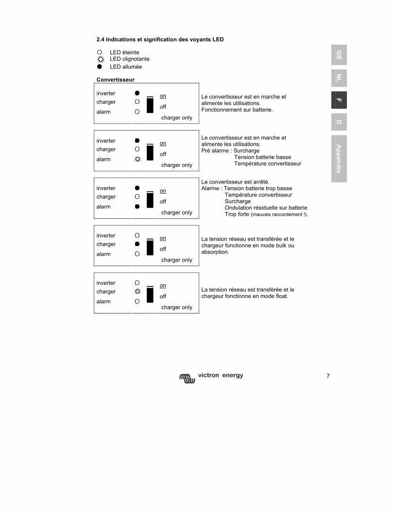
7
GB
N
L F
D
Appendix
2.4 Indications et signification des voyants LED LED éteinte
LED clignotante LED allumée Convertisseur inverter on charger off alarm
charger only
Le convertisseur est en marche et alimente les utilisations. Fonctionnement sur batterie.
inverter on charger off alarm
charger only
Le convertisseur est en marche et alimente les utilisations. Pré alarme : Surcharge Tension batterie basse Température convertisseur
inverter on charger off alarm
charger only
Le convertisseur est arrêté. Alarme : Tension batterie trop basse Température convertisseur Surcharge Ondulation résiduelle sur batterie Trop forte (mauvais raccordement !).
inverter on charger off alarm
charger only
La tension réseau est transférée et le chargeur fonctionne en mode bulk ou absorption.
inverter on charger off alarm
charger only
La tension réseau est transférée et le chargeur fonctionne en mode float.
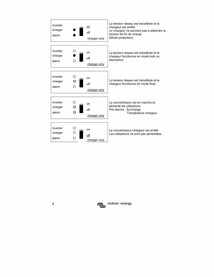
8
inverter on charger off alarm
charger only
La tension réseau est transférée et le chargeur est arrêté. Le chargeur ne parvient pas à atteindre la tension de fin de charge (Mode protection).
inverter on charger
off alarm
charger only
La tension réseau est transférée et le chargeur fonctionne en mode bulk ou absorption.
inverter on charger
off alarm
charger only
La tension réseau est transférée et le chargeur fonctionne en mode float.
inverter on charger
off alarm
charger only
Le convertisseur est en marche et alimente les utilisations. Pré alarme : Surcharge Température chargeur
inverter on charger
off alarm
charger only
Le convertisseur-chargeur est arrêté Les utilisations ne sont pas alimentées.
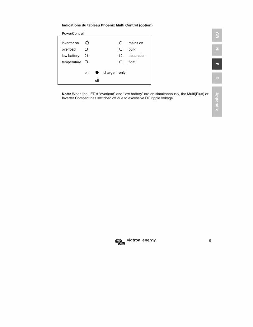
9
GB
N
L F
D
Appendix
Indications du tableau Phoenix Multi Control (option) PowerControl inverter on mains on overload bulk
low battery absorption
temperature
float
on charger only
off
Note: When the LED’s “overload” and “low battery” are on simultaneously, the Multi(Plus) or Inverter Compact has switched off due to excessive DC ripple voltage.
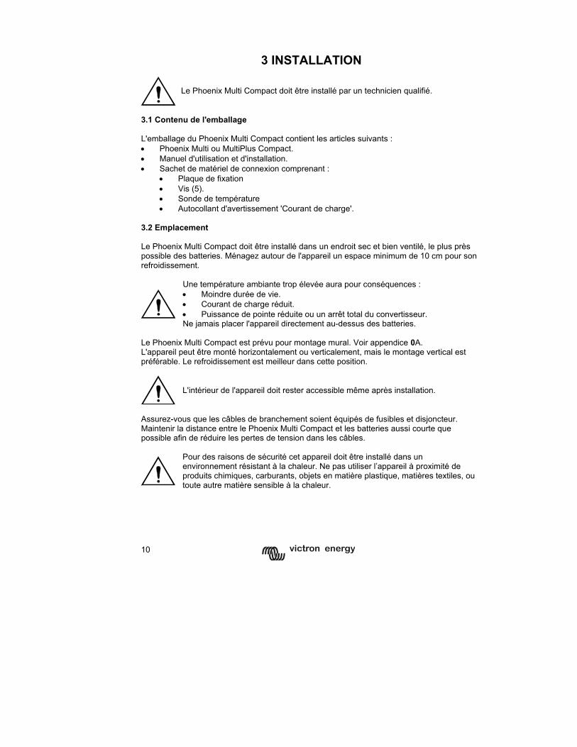
10
3 INSTALLATION
Le Phoenix Multi Compact doit être installé par un technicien qualifié.
3.1 Contenu de l'emballage L'emballage du Phoenix Multi Compact contient les articles suivants : • Phoenix Multi ou MultiPlus Compact. • Manuel d'utilisation et d'installation. • Sachet de matériel de connexion comprenant :
• Plaque de fixation • Vis (5). • Sonde de température • Autocollant d'avertissement 'Courant de charge'.
3.2 Emplacement Le Phoenix Multi Compact doit être installé dans un endroit sec et bien ventilé, le plus près possible des batteries. Ménagez autour de l'appareil un espace minimum de 10 cm pour son refroidissement.
Une température ambiante trop élevée aura pour conséquences : • Moindre durée de vie. • Courant de charge réduit. • Puissance de pointe réduite ou un arrêt total du convertisseur. Ne jamais placer l'appareil directement au-dessus des batteries.
Le Phoenix Multi Compact est prévu pour montage mural. Voir appendice 0A. L'appareil peut être monté horizontalement ou verticalement, mais le montage vertical est préférable. Le refroidissement est meilleur dans cette position.
L'intérieur de l'appareil doit rester accessible même après installation.
Assurez-vous que les câbles de branchement soient équipés de fusibles et disjoncteur. Maintenir la distance entre le Phoenix Multi Compact et les batteries aussi courte que possible afin de réduire les pertes de tension dans les câbles.
Pour des raisons de sécurité cet appareil doit être installé dans un environnement résistant à la chaleur. Ne pas utiliser l’appareil à proximité de produits chimiques, carburants, objets en matière plastique, matières textiles, ou toute autre matière sensible à la chaleur.
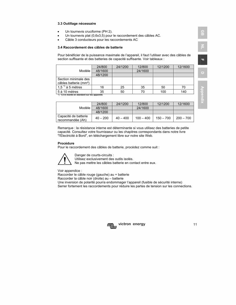
11
GB
N
L F
D
Appendix
3.3 Outillage nécessaire • Un tournevis cruciforme (PH 2). • Un tournevis plat (0,6x3,5) pour le raccordement des câbles AC. • Câble 3 conducteurs pour les raccordements AC 3.4 Raccordement des câbles de batterie Pour bénéficier de la puissance maximale de l’appareil, il faut l’utiliser avec des câbles de section suffisante et des batteries de capacité suffisante. Voir tableaux :
24/800 24/1200 12/800 12/1200 12/1600 48/1600 24/1600 Modèle 48/1200
Section minimale des câbles batterie (mm²)
1,5 1) à 5 mètres 16 25 35 50 70 5 à 10 mètres 35 50 70 100 140 1) 1,5 m monté en standard sur les appareils
24/800 24/1200 12/800 12/1200 12/1600 48/1600 24/1600 Modèle 48/1200
Capacité de batterie recommandée (Ah) 40 – 200 40 – 400 100 – 400 150 – 700 200 – 700
Remarque : la résistance interne est déterminante si vous utilisez des batteries de petite capacité. Consultez votre fournisseur ou les chapitres correspondants dans notre livre "l'Electricité à Bord", en téléchargement libre sur notre site Web. Procédure Pour le raccordement des câbles de batterie, procédez comme suit :
Danger de courts-circuits : Utilisez exclusivement des outils isolés. Ne pas mettre les câbles batterie en contact entre eux.
Voir appendice : Raccorder le câble rouge (gauche) au + batterie Raccorder la câble noir (droite) au – batterie Une inversion de polarité pourra endommager l’appareil (fusible de sécurité interne) Serrer fortement les raccordements pour réduire les partes de tension sur les connections.
12
3.5 Connexion des câbles AC
Ce produit est issu de la classe sécurité I. (livré avec une prise de mise à la terre de protection). Une liaison permanente à la terre doit être réalisée au niveau de la ou des prises de raccordement AC ou sur la borne de raccordement situé sur l’extérieur du boîtier. Voir les instructions suivantes : a) Le Phoenix Inverter Compact a une tension de sortie flottante. Le boîtier doit impérativement être relié à la terre par la borne de raccordement située sur l’extérieur du boîtier. Pour le bon fonctionnement d’un disjoncteur différentiel le neutre de sortie (N) doit également être relié à la terre. b) Le Phoenix Multi / MultiPlus Compact est équipé d’un relais de mise à la terre (voir appendice 2) qui relie automatiquement le neutre de sortie (N) à la terre en cas d’absence d’alimentation AC sur l’entrée. Dès qu’une alimentation AC est présente sur l’entrée le relais de mise à la terre s’ouvre avant la fermeture du relais de sécurité en entrée. Ce dispositif permet d’assurer le bon fonctionnement d’un disjoncteur différentiel en sortie. - Dans une installation fixe avec neutre identifié une liaison permanente à la terre pourra être réalisée avec le conducteur de terre de l’alimentation AC. Dans le cas contraire c’est le boîtier qu’il faut relier à la terre. - Dans une installation mobile (par exemple avec prise de quai, où la position du neutre est incertaine) la coupure de l’alimentation en entrée coupera également la liaison à la terre. Dans ce cas le boîtier doit être relié au châssis (du véhicule) ou à la coque ou plaque de masse (du navire). - La liaison à la terre du quai décrite ci-dessus est en général déconseillée en vue des risques de corrosion galvanique. Une bonne solution sera la mise en place d’un transformateur d’isolement.
Le Phoenix Multi Compact est équipé de fiches d’entrée et de sortie de Typ G-ST18i, situées sous l’appareil. Utiliser des câbles de raccordement souples à 3 conducteurs (Typ H05RN-F) de section suffisante : 1,5 mm² jusqu’à 800VA et 2,5mm² pour les puissances supérieures. Procédure Procéder comme suit pour les raccordements AC : Le câble de sortie AC se raccorde sur la fiche mâle G-ST18i. Utiliser un câble à trois conducteurs. Les raccordements sont repérés à l’intérieur de la prise : Gauche “N” (neutre), milieu terre, droite “L1” (phase). Le câble d’alimentation AC se raccorde sur la fiche femelle G-ST18i. Utiliser un câble à trois conducteurs. Les raccordements sont repérés à l’intérieur de la prise : Gauche “L1” (phase), milieu terre, droite “N” (neutre). Insérer la fiche G-ST18i d’alimentation sur la prise mâle de l’appareil (côté arrière). Insérer la fiche G-ST18i de sortie sur la prise femelle de l’appareil (côté face).
13
GB
N
L F
D
Appendix
3.6 Raccordement d'options En plus des raccordements standard, plusieurs raccordements optionnels sont possibles. 3.6.1 Batterie auxiliaire (de démarrage) Le Phoenix Multi Compact est équipé d'une sortie auxiliaire pour la charge d'une batterie de démarrage. Pour le raccordement voir appendice 1.
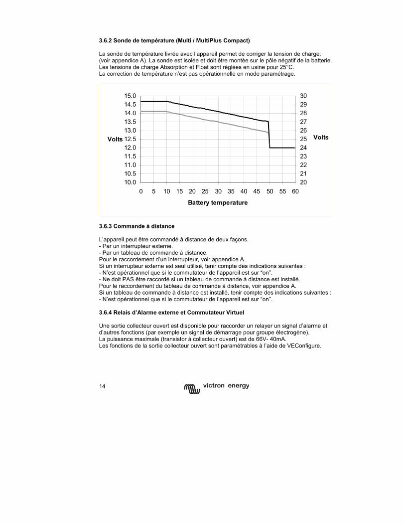
14
3.6.2 Sonde de température (Multi / MultiPlus Compact) La sonde de température livrée avec l’appareil permet de corriger la tension de charge. (voir appendice A). La sonde est isolée et doit être montée sur le pôle négatif de la batterie. Les tensions de charge Absorption et Float sont réglées en usine pour 25°C. La correction de température n’est pas opérationnelle en mode paramétrage.
10.010.511.011.512.012.513.013.514.014.515.0
0 5 10 15 20 25 30 35 40 45 50 55 60
Battery temperature
Volts
2021222324252627282930
Volts
3.6.3 Commande à distance L’appareil peut être commandé à distance de deux façons. - Par un interrupteur externe. - Par un tableau de commande à distance. Pour le raccordement d’un interrupteur, voir appendice A. Si un interrupteur externe est seul utilisé, tenir compte des indications suivantes : - N’est opérationnel que si le commutateur de l’appareil est sur “on”. - Ne doit PAS être raccordé si un tableau de commande à distance est installé. Pour le raccordement du tableau de commande à distance, voir appendice A. Si un tableau de commande à distance est installé, tenir compte des indications suivantes : - N’est opérationnel que si le commutateur de l’appareil est sur “on”. 3.6.4 Relais d’Alarme externe et Commutateur Virtuel Une sortie collecteur ouvert est disponible pour raccorder un relayer un signal d’alarme et d’autres fonctions (par exemple un signal de démarrage pour groupe électrogène). La puissance maximale (transistor à collecteur ouvert) est de 66V- 40mA. Les fonctions de la sortie collecteur ouvert sont paramétrables à l’aide de VEConfigure.
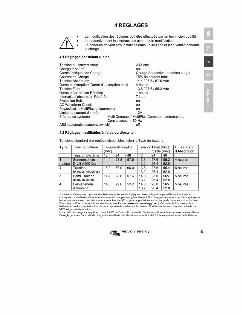
15
GB
N
L F
D
Appendix
4 REGLAGES
• La modification des réglages doit être effectuée par un technicien qualifié. • Lire attentivement les instructions avant toute modification. • Le batteries doivent être installées dans un lieu sec et bien ventilé pendant
la charge. 4.1 Réglages par défaut (usine) Tension du convertisseur 230 Vac Chargeur on/ off on Caractéristiques de Charge Charge Adaptative, batteries au gel Courant de Charge 75% du courant maxi Tension Absorption 14.4 / 28.8 / 57.6 Vdc Durée d’absorption/ Durée d’absorption maxi 4 heures Tension Float 13.8 / 27.6 / 55.2 Vdc Durée d’Absorption Répétée 1 heure Intervalle d’absorption Répétée 7 jours Protection Bulk on AC Waveform Check on PowerAssist (MultiPlus uniquement) on Limite de courant d’entrée 12A Fréquence système - Multi Compact / MultiPlus Compact = automatique - Convertisseur = 50 Hz AES (automatic economy switch) off 4.2 Réglages modifiables à l’aide du dipswitch Tensions standard pré-réglées disponibles selon le Type de batterie
Type Type de batterie Tension Absorption (Vdc)
Tension Float (Vdc) Veille (Vdc)
Durée maxi d’Absorption
Tension système 12 24 48 12 24 48 1 (usine)
Sonnenschein Dryfit A200 Gel
14.4 28.8 57.6 13.8 13.2
27.6 26.4
55.2 52.8
4 heures
2 Traction (plaques tubulaires)
15.0 30.0 60.0 13.8 13.2
27.6 26.4
55.4 52.8
6 heures
3 Semi Traction1
(plaques planes) 14.4 28.8 57.6 14.0
13.2 28.0 26.4
56V 52.8
5 heures
4 Faible teneur Antimoine1
14.8 29.6 59.2 14.0 13.2
28.0 26.4
56V 52.8
5 heures
1La tension d'absorption optimale des batteries plomb-acide à plaques planes dépend de propriétés mécaniques et chimiques. Les batteries à haute teneur en antimoine peuvent généralement être chargées à une tension d'absorption plus basse que celles avec une faible teneur en antimoine. (Pour plus de précisions sur la charge de batteries, voir notre livre 'Electricity on Board’ disponible en téléchargement libre sur www.victronenergy.com). Consulter le fournisseur des batteries ou la documentation fournie pour connaître les valeurs préconisées. Modifier les tensions standard à l’aide de VEConfigure si nécessaire. L’intensité de charge est réglée en usine à 75% de l’intensité maximale. Cette intensité sera dans certains cas trop élevée. En règle générale l’intensité de charge d’une batterie doit être située entre 0,1 et 0,2 fois la capacité totale de la batterie.
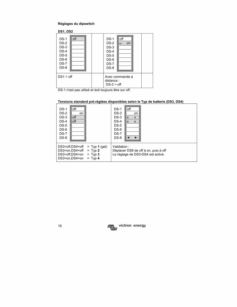
16
Réglages du dipswitch DS1, DS2 DS-1 off DS-2 DS-3 DS-4 DS-5 DS-6 DS-7 DS-8
DS-1 off DS-2 ← onDS-3 DS-4 DS-5 DS-6 DS-7 DS-8
DS1 = off Avec commande à distance : DS-2 = off
DS-1 n'est pas utilisé et doit toujours être sur off. Tensions standard pré-réglées disponibles selon le Typ de batterie (DS3, DS4) DS-1 off DS-2 on DS-3 off DS-4 off DS-5 DS-6 DS-7 DS-8
DS-1 off DS-2 onDS-3 x x DS-4 x x DS-5 DS-6 DS-7 DS-8
DS3=off,DS4=off = Typ 1 (gel) DS3=on,DS4=off = Typ 2 DS3=off,DS4=on = Typ 3 DS3=on,DS4=on = Typ 4
Validation : Déplacer DS8 de off à on, puis à off Le réglage de DS3-DS4 est activé.
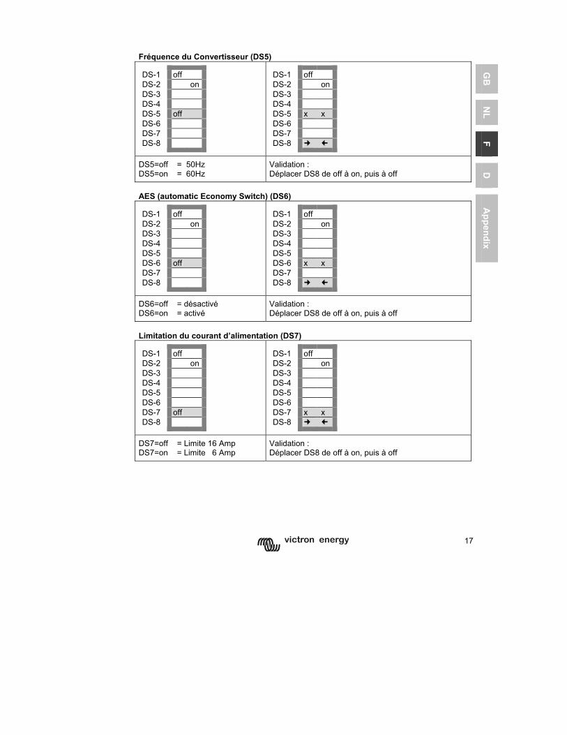
17
GB
N
L F
D
Appendix
Fréquence du Convertisseur (DS5) DS-1 off DS-2 on DS-3 DS-4 DS-5 off DS-6 DS-7 DS-8
DS-1 off DS-2 onDS-3 DS-4 DS-5 x x DS-6 DS-7 DS-8
DS5=off = 50Hz DS5=on = 60Hz
Validation : Déplacer DS8 de off à on, puis à off
AES (automatic Economy Switch) (DS6) DS-1 off DS-2 on DS-3 DS-4 DS-5 DS-6 off DS-7 DS-8
DS-1 off DS-2 onDS-3 DS-4 DS-5 DS-6 x x DS-7 DS-8
DS6=off = désactivé DS6=on = activé
Validation : Déplacer DS8 de off à on, puis à off
Limitation du courant d’alimentation (DS7) DS-1 off DS-2 on DS-3 DS-4 DS-5 DS-6 DS-7 off DS-8
DS-1 off DS-2 onDS-3 DS-4 DS-5 DS-6 DS-7 x x DS-8
DS7=off = Limite 16 Amp DS7=on = Limite 6 Amp
Validation : Déplacer DS8 de off à on, puis à off
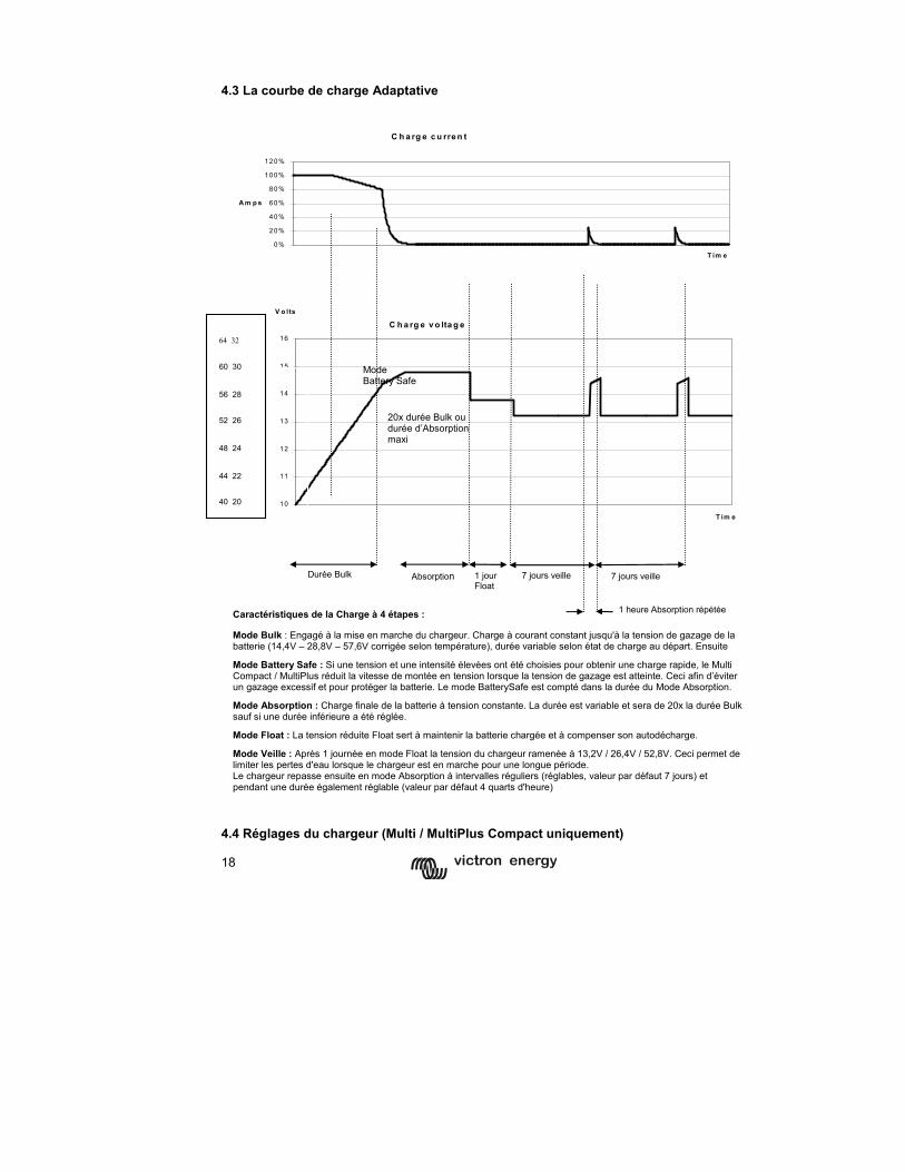
18
4.3 La courbe de charge Adaptative
4.4 Réglages du chargeur (Multi / MultiPlus Compact uniquement)
C h a rg e c u rre n t
0%
20%
40%
60%
80%
100%
120%
T im e
A m p s
C h a rg e v o lta g e
10
11
12
13
14
15
16
T im e
V o lts
Caractéristiques de la Charge à 4 étapes :
Mode Bulk : Engagé à la mise en marche du chargeur. Charge à courant constant jusqu'à la tension de gazage de la batterie (14,4V – 28,8V – 57,6V corrigée selon température), durée variable selon état de charge au départ. Ensuite Mode Battery Safe : Si une tension et une intensité élevées ont été choisies pour obtenir une charge rapide, le Multi Compact / MultiPlus réduit la vitesse de montée en tension lorsque la tension de gazage est atteinte. Ceci afin d’éviter un gazage excessif et pour protéger la batterie. Le mode BatterySafe est compté dans la durée du Mode Absorption. Mode Absorption : Charge finale de la batterie à tension constante. La durée est variable et sera de 20x la durée Bulk sauf si une durée inférieure a été réglée. Mode Float : La tension réduite Float sert à maintenir la batterie chargée et à compenser son autodécharge. Mode Veille : Après 1 journée en mode Float la tension du chargeur ramenée à 13,2V / 26,4V / 52,8V. Ceci permet de limiter les pertes d'eau lorsque le chargeur est en marche pour une longue période. Le chargeur repasse ensuite en mode Absorption à intervalles réguliers (réglables, valeur par défaut 7 jours) et pendant une durée également réglable (valeur par défaut 4 quarts d'heure)
20x durée Bulk ou durée d’Absorption maxi
Durée Bulk 1 jour Float
7 jours veille Absorption
1 heure Absorption répétée
7 jours veille
Mode Battery Safe
64 32 60 30 56 28 52 26 48 24 44 22 40 20
19
GB
N
L F
D
Appendix
Les réglages suivants sont modifiables uniquement avec VEConfigure
Arrêt du chargeur (usine : marche) Pour une utilisation de l’appareil en uniquement en convertisseur il est possible de désactiver le chargeur. Le commutateur de transfert rapide reste opérationnel.
4.4.1 Les trois courbes de charge préprogrammées Pour plus de précisions sur la charge de batteries, voir notre livre 'Electrivity on Board’ disponible en téléchargement libre sur www.victronenergy.com. Consulter le fournisseur des batteries ou la documentation fournie pour connaître les valeurs préconisées.
Le Phoenix Multi / MultiPlus Compact propose en standard trois courbes de charge (voir aussi les explications et graphiques au 4.3 page précédente):
Courbe fixe à 3 étapes de charge La durée de la phase de charge d’Absorption est fixe et réglable. Après la phase d’Absorption le chargeur passe en mode Float pour une durée également réglable et revient ensuite périodiquement en mode Absorption pour des durées généralement courtes.
Courbe Adaptative à 4 étapes de charge La durée de la phase de charge d’Absorption est déterminée par le chargeur en fonction du déroulement de la phase de charge Bulk. Vient ensuite le mode Float pendant 24 heures, suivie d’un mode Veille où la tension est réduite à 13 / 26 / 52 V. Comme pour la courbe fixe, le chargeur revient ensuite en mode Absorption à intervalles réguliers (intervalles et durée réglables)
Courbe Adaptative avec mode BatterySafe (réglage usine) Si une tension et une intensité élevées ont été choisies pour obtenir une charge rapide, le Multi Compact / MultiPlus réduit la vitesse de montée en tension lorsque la tension de gazage est atteinte. Ceci afin d’éviter un gazage excessif et pour protéger la batterie
4.4.2 Autres réglages
Courant de charge (usine : 75%) Le courant de charge est réglé en usine à 75% du maximum. Cette intensité sera dans certains cas trop élevée. En règle générale l’intensité de charge d’une batterie doit être située entre 0,1 et 0,2 fois la capacité totale de la batterie.
Durée d'absorption/ durée d'absorption maximum (usine : 4 heures) En courbe de charge fixe ce réglage détermine la durée de la phase de charge en mode Absorption. En courbe de charge adaptative, ce réglage détermine la durée maximale de la phase de charge en mode Absorption, indépendamment des calculs automatiques du chargeur. La durée (maximum) d'absorption peut être réglée de 1 à 12 heures.
Tension de charge Absorption et Float Si les valeurs réglées en usine ne conviennent pas à l’application, il est possible de les modifier
Intervalle et durée d’Absorption répétée (usine : 1 heure tous les 7 jours) Si les valeurs réglées en usine ne conviennent pas à l’application, il est possible de les modifier
20
4.5 Réglages spéciaux Les réglages suivants sont modifiables uniquement avec VEConfigure Bulk Protection (protection volumétrique) : (usine : on) Si après 10 heures de charge en mode Bulk le chargeur n'a pas atteint la tension d'absorption, il se peut que la batterie soit défectueuse. Par sécurité le chargeur s’arrête automatiquement au bout de 10 heures de charge en mode Bulk. Le voyant rouge “alarme“ sur l’appareil s’allume (ou le voyant “Bulk“ sur le tableau de commande Phoenix Multi Control).
AC Waveform Check (vérification de la forme d’onde) : (usine : on) L’appareil vérifie non seulement la valeur de sa tension d’alimentation, mais aussi la qualité de l’onde sinusoïdale. Si l’appareil fonctionne mal quand il est alimenté par un groupe électrogène, cette fonction peut être désactivée.
PowerControl : s’adapter au limites d’un groupe ou du quai (usine : 16A) Pour la protéger la source d’alimentation de l’appareil (groupe électrogène, prise de quai…) le courant de charge disponible pour les batteries est automatiquement réglé de manière à ce que la puissance totale demandée par l’appareil (soit les puissances additionnées du chargeur et des utilisations en sortie) ne dépasse pas un niveau déterminé. Si la consommation AC dépasse ce niveau, le chargeur est désactivé et la LED “mains on” clignote. Il est alors possible que le disjoncteur secteur (quai) saute ou que le générateur s'arrête en raison de surcharge. Le Multi Compact tentera de passer en mode convertisseur. La puissance générateur/ courant secteur peut être réglée de 1 à 16A.
Le réglage sur le tableau de commande à distance annule le réglage interne.
PowerAssist : fourniture de puissance supplémentaire par le convertisseur. MultiPlus uniquement (usine : on) PowerAssist est une fonction supplémentaire qui distingue le MultiPlus Compact du Multi Compact. Le MultiPlus travaille en parallèle avec la source d’alimentation (groupe électrogène, prise de quai…) et permet de doubler la puissance disponible : lorsque la limite fixée (voir PowerControl) est dépassée le convertisseur du MultiPlus fournit le complément à partir de la batterie. Il est ainsi possible de faire face à des surcharges momentanées. Toute puissance excédentaire disponible en entrée est automatiquement utilisée pour la (re)charge de la batterie. Note 1 : Pour le bon fonctionnement de PowerAssist il faut disposer d’au moins 2A au secteur (quai) ou d’un groupe électrogène d’une puissance au moins égale à celle du MultiPlus. Note 2 : Certains groupes électrogènes modernes utilisent un convertisseur pour produire leur tension de sortie ("Inverter technology"). Certains de ces groupes diminuent aussi de régime en cas de faible charge. La fonction "Dynamic current limit" dans VEConfigure permet au MultiPlus d'effacer des augmentations de puissance soudaines en attendant qu'un groupe de ce Typ remonte en régime. Relais d’Alarme externe et Commutateur Virtuel Une sortie collecteur ouvert est disponible pour raccorder un relayer un signal d’alarme et d’autres fonctions (par exemple un signal de démarrage pour groupe électrogène). La puissance maximale (transistor à collecteur ouvert) est de 66V - 40mA. Les fonctions de la sortie collecteur ouvert sont paramétrables à l’aide de VEConfigure. 4.6 Entretien Le Phoenix Multi Compact ne nécessite pas d'entretien spécifique. Contrôler l'ensemble des connexions une fois par an et dépoussiérez si nécessaire. Protéger l'appareil contre l'humidité, les salissures et les fumées grasses.
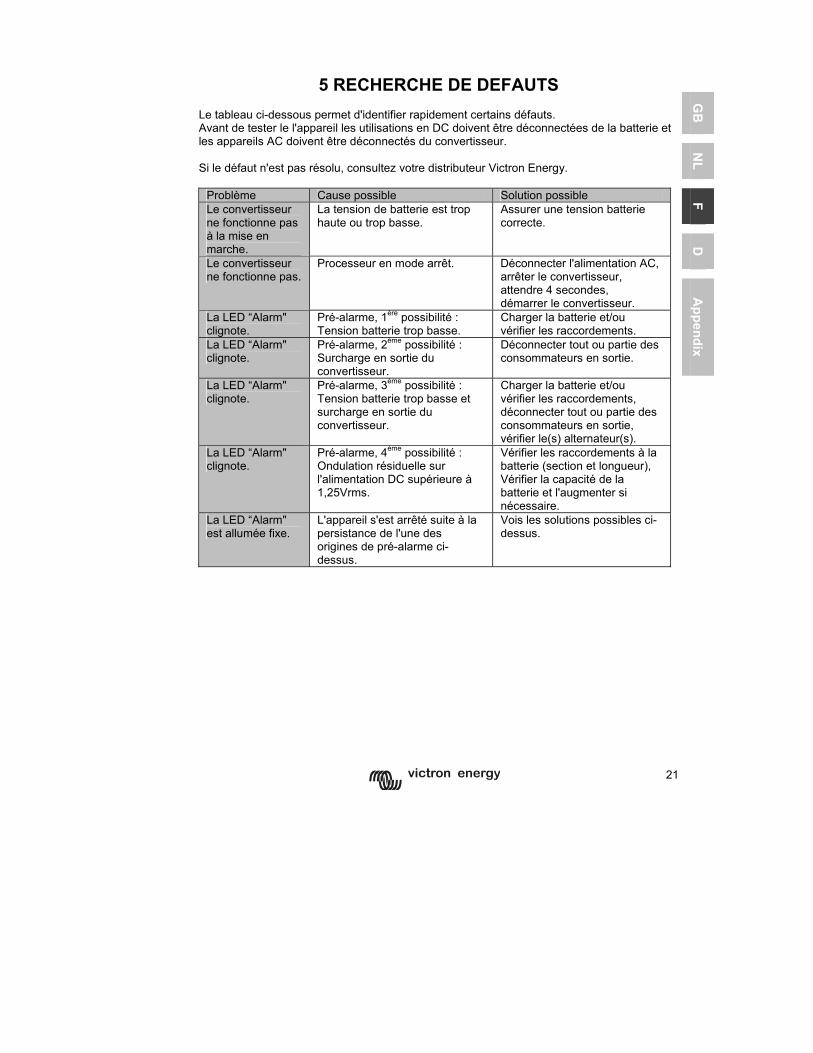
21
GB
N
L F
D
Appendix
5 RECHERCHE DE DEFAUTS
Le tableau ci-dessous permet d'identifier rapidement certains défauts. Avant de tester le l'appareil les utilisations en DC doivent être déconnectées de la batterie et les appareils AC doivent être déconnectés du convertisseur. Si le défaut n'est pas résolu, consultez votre distributeur Victron Energy.
Problème Cause possible Solution possible Le convertisseur ne fonctionne pas à la mise en marche.
La tension de batterie est trop haute ou trop basse.
Assurer une tension batterie correcte.
Le convertisseur ne fonctionne pas.
Processeur en mode arrêt. Déconnecter l'alimentation AC, arrêter le convertisseur, attendre 4 secondes, démarrer le convertisseur.
La LED “Alarm" clignote.
Pré-alarme, 1ère possibilité : Tension batterie trop basse.
Charger la batterie et/ou vérifier les raccordements.
La LED “Alarm" clignote.
Pré-alarme, 2ème possibilité : Surcharge en sortie du convertisseur.
Déconnecter tout ou partie des consommateurs en sortie.
La LED “Alarm" clignote.
Pré-alarme, 3ème possibilité : Tension batterie trop basse et surcharge en sortie du convertisseur.
Charger la batterie et/ou vérifier les raccordements, déconnecter tout ou partie des consommateurs en sortie, vérifier le(s) alternateur(s).
La LED “Alarm" clignote.
Pré-alarme, 4ème possibilité : Ondulation résiduelle sur l'alimentation DC supérieure à 1,25Vrms.
Vérifier les raccordements à la batterie (section et longueur), Vérifier la capacité de la batterie et l'augmenter si nécessaire.
La LED “Alarm" est allumée fixe.
L'appareil s'est arrêté suite à la persistance de l'une des origines de pré-alarme ci-dessus.
Vois les solutions possibles ci-dessus.
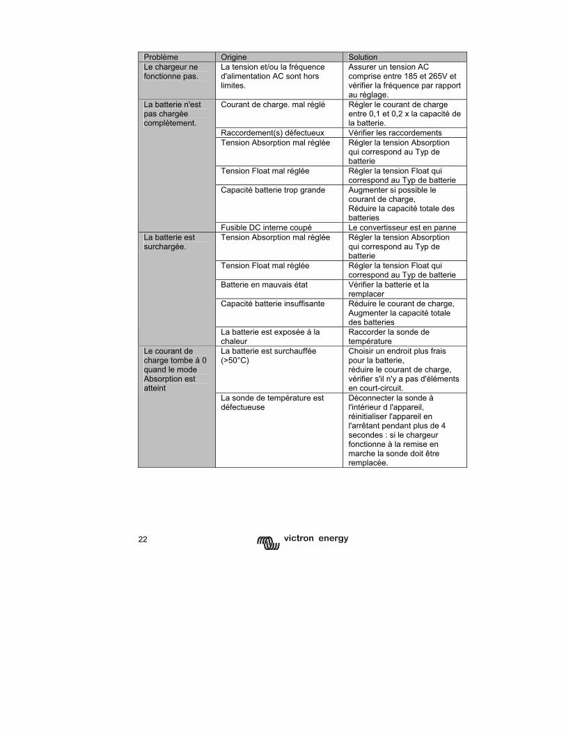
22
Problème Origine Solution Le chargeur ne fonctionne pas.
La tension et/ou la fréquence d'alimentation AC sont hors limites.
Assurer un tension AC comprise entre 185 et 265V et vérifier la fréquence par rapport au réglage.
Courant de charge. mal réglé Régler le courant de charge entre 0,1 et 0,2 x la capacité de la batterie.
Raccordement(s) défectueux Vérifier les raccordements Tension Absorption mal réglée Régler la tension Absorption
qui correspond au Typ de batterie
Tension Float mal réglée Régler la tension Float qui correspond au Typ de batterie
Capacité batterie trop grande Augmenter si possible le courant de charge, Réduire la capacité totale des batteries
La batterie n'est pas chargée complètement.
Fusible DC interne coupé Le convertisseur est en panne Tension Absorption mal réglée Régler la tension Absorption
qui correspond au Typ de batterie
Tension Float mal réglée Régler la tension Float qui correspond au Typ de batterie
Batterie en mauvais état Vérifier la batterie et la remplacer
Capacité batterie insuffisante Réduire le courant de charge, Augmenter la capacité totale des batteries
La batterie est surchargée.
La batterie est exposée à la chaleur
Raccorder la sonde de température
La batterie est surchauffée (>50°C)
Choisir un endroit plus frais pour la batterie, réduire le courant de charge, vérifier s'il n'y a pas d'éléments en court-circuit.
Le courant de charge tombe à 0 quand le mode Absorption est atteint
La sonde de température est défectueuse
Déconnecter la sonde à l'intérieur d l'appareil, réinitialiser l'appareil en l'arrêtant pendant plus de 4 secondes : si le chargeur fonctionne à la remise en marche la sonde doit être remplacée.
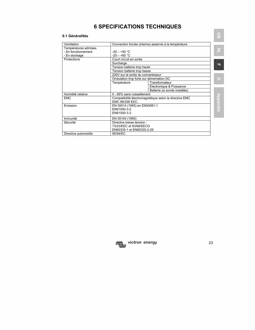
23
GB
N
L F
D
Appendix
6 SPECIFICATIONS TECHNIQUES
6.1 Généralités Ventilation Convection forcée (interne) asservie à la température Températures admises - En fonctionnement - En stockage
-20 – +50 °C -25 – +60 °C Court circuit en sortie Surcharge Tension batterie trop haute Tension batterie trop basse 230V sur la sortie du convertisseur Ondulation trop forte sur alimentation DC
Transformateur Electronique & Puissance
Protections
Température
Batterie (si sonde installée) Humidité relative 0 -.95% sans ruissellement EMC Compatibilité électromagnétique selon la directive EMC
EMC 89/336 EEC. Emission EN 55014 (1993) en EN50081-1
EN61000-3-2 EN61000-3-3
Immunité EN 55104 (1995) Sécurité Directive basse tension :
73/23/EEC et 93/68/EECG EN60335-1 et EN60335-2-29
Directive automobile 95/54/EC
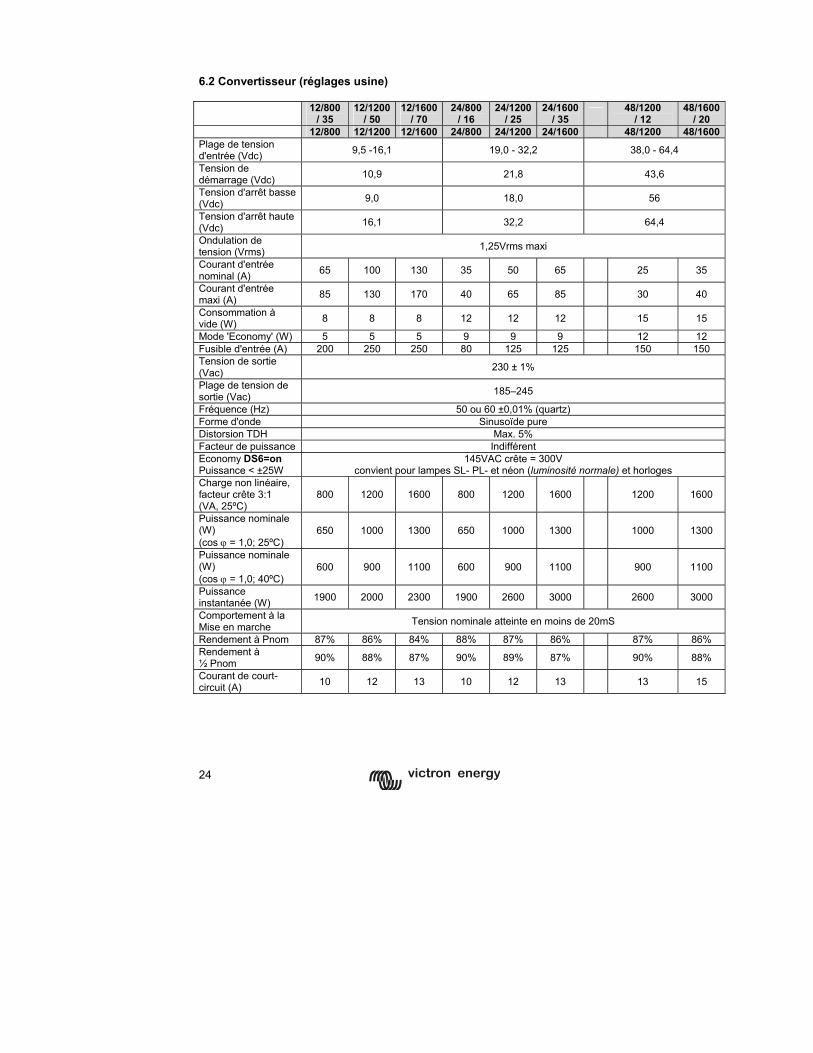
24
6.2 Convertisseur (réglages usine)
12/800 / 35
12/1200/ 50
12/1600/ 70
24/800 / 16
24/1200/ 25
24/1600 / 35 48/1200
/ 12 48/1600
/ 20 12/800 12/1200 12/1600 24/800 24/1200 24/1600 48/1200 48/1600
Plage de tension d'entrée (Vdc) 9,5 -16,1 19,0 - 32,2 38,0 - 64,4
Tension de démarrage (Vdc) 10,9 21,8 43,6
Tension d'arrêt basse (Vdc) 9,0 18,0 56
Tension d'arrêt haute (Vdc) 16,1 32,2 64,4
Ondulation de tension (Vrms) 1,25Vrms maxi
Courant d'entrée nominal (A) 65 100 130 35 50 65 25 35
Courant d'entrée maxi (A) 85 130 170 40 65 85 30 40
Consommation à vide (W) 8 8 8 12 12 12 15 15
Mode 'Economy' (W) 5 5 5 9 9 9 12 12 Fusible d'entrée (A) 200 250 250 80 125 125 150 150 Tension de sortie (Vac) 230 ± 1%
Plage de tension de sortie (Vac) 185–245
Fréquence (Hz) 50 ou 60 ±0,01% (quartz) Forme d'onde Sinusoïde pure Distorsion TDH Max. 5% Facteur de puissance Indifférent Economy DS6=on Puissance < ±25W
145VAC crête = 300V convient pour lampes SL- PL- et néon (luminosité normale) et horloges
Charge non linéaire, facteur crête 3:1 (VA, 25ºC)
800 1200 1600 800 1200 1600 1200 1600
Puissance nominale (W) (cos ϕ = 1,0; 25ºC)
650 1000 1300 650 1000 1300 1000 1300
Puissance nominale (W) (cos ϕ = 1,0; 40ºC)
600 900 1100 600 900 1100 900 1100
Puissance instantanée (W) 1900 2000 2300 1900 2600 3000 2600 3000
Comportement à la Mise en marche Tension nominale atteinte en moins de 20mS
Rendement à Pnom 87% 86% 84% 88% 87% 86% 87% 86% Rendement à ½ Pnom 90% 88% 87% 90% 89% 87% 90% 88%
Courant de court-circuit (A) 10 12 13 10 12 13 13 15
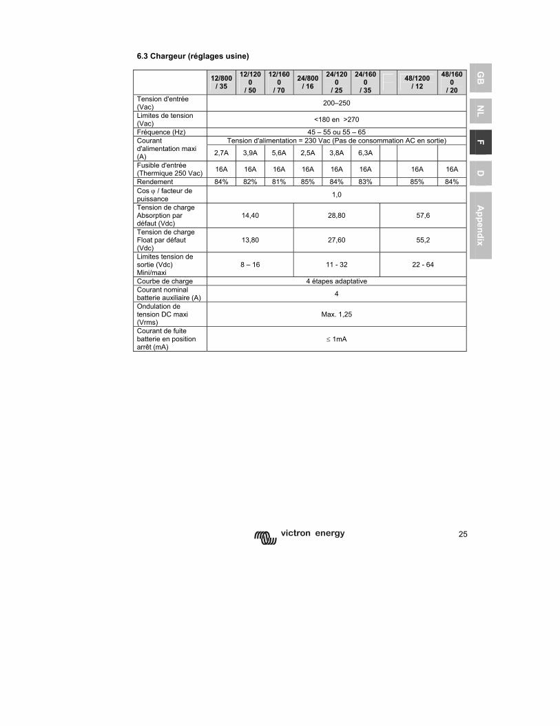
25
GB
N
L F
D
Appendix
6.3 Chargeur (réglages usine) 12/800
/ 35 12/120
0 / 50
12/1600
/ 70 24/800
/ 16 24/120
0 / 25
24/1600
/ 35
48/1200 / 12
48/1600
/ 20 Tension d'entrée (Vac) 200–250
Limites de tension (Vac) <180 en >270
Fréquence (Hz) 45 – 55 ou 55 – 65 Tension d'alimentation = 230 Vac (Pas de consommation AC en sortie) Courant
d'alimentation maxi (A) 2,7A 3,9A 5,6A 2,5A 3,8A 6,3A
Fusible d'entrée (Thermique 250 Vac) 16A 16A 16A 16A 16A 16A 16A 16A
Rendement 84% 82% 81% 85% 84% 83% 85% 84% Cos ϕ / facteur de puissance 1,0
Tension de charge Absorption par défaut (Vdc)
14,40 28,80 57,6
Tension de charge Float par défaut (Vdc)
13,80 27,60 55,2
Limites tension de sortie (Vdc) Mini/maxi
8 – 16 11 - 32 22 - 64
Courbe de charge 4 étapes adaptative Courant nominal batterie auxiliaire (A) 4
Ondulation de tension DC maxi (Vrms)
Max. 1,25
Courant de fuite batterie en position arrêt (mA)
≤ 1mA
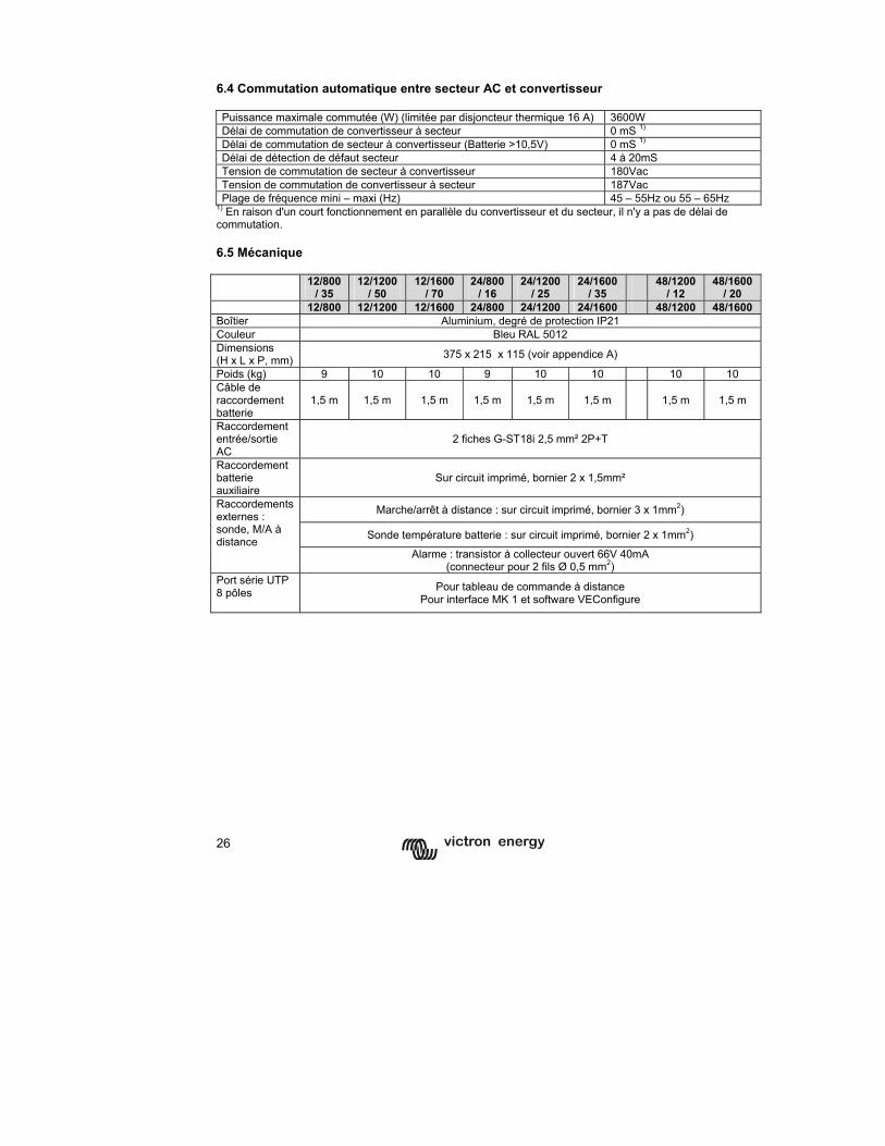
26
6.4 Commutation automatique entre secteur AC et convertisseur Puissance maximale commutée (W) (limitée par disjoncteur thermique 16 A) 3600W Délai de commutation de convertisseur à secteur 0 mS 1) Délai de commutation de secteur à convertisseur (Batterie >10,5V) 0 mS 1) Délai de détection de défaut secteur 4 à 20mS Tension de commutation de secteur à convertisseur 180Vac Tension de commutation de convertisseur à secteur 187Vac Plage de fréquence mini – maxi (Hz) 45 – 55Hz ou 55 – 65Hz
1) En raison d'un court fonctionnement en parallèle du convertisseur et du secteur, il n'y a pas de délai de commutation. 6.5 Mécanique 12/800
/ 35 12/1200
/ 50 12/1600
/ 70 24/800
/ 16 24/1200
/ 25 24/1600
/ 35
48/1200 / 12
48/1600 / 20
12/800 12/1200 12/1600 24/800 24/1200 24/1600 48/1200 48/1600 Boîtier Aluminium, degré de protection IP21 Couleur Bleu RAL 5012 Dimensions (H x L x P, mm) 375 x 215 x 115 (voir appendice A)
Poids (kg) 9 10 10 9 10 10 10 10 Câble de raccordement batterie
1,5 m 1,5 m 1,5 m 1,5 m 1,5 m 1,5 m 1,5 m 1,5 m
Raccordement entrée/sortie AC
2 fiches G-ST18i 2,5 mm² 2P+T
Raccordement batterie auxiliaire
Sur circuit imprimé, bornier 2 x 1,5mm²
Marche/arrêt à distance : sur circuit imprimé, bornier 3 x 1mm2)
Sonde température batterie : sur circuit imprimé, bornier 2 x 1mm2)
Raccordements externes : sonde, M/A à distance
Alarme : transistor à collecteur ouvert 66V 40mA (connecteur pour 2 fils Ø 0,5 mm2)
Port série UTP 8 pôles Pour tableau de commande à distance
Pour interface MK 1 et software VEConfigure
27
GB
N
L F
D
Appendix

1
GB
N
L F
D
Appendix
Copyright 2005 Victron Energy B.V. Alle Rechte vorbehalten.
Diese Veröffentlichung oder Auszüge daraus dürfen nicht in jedweder Form, Methode oder zu irgendeinem Zweck kopiert oder vervielfältigt werden Um diese Anleitung in einer anderen Sprache als in Englisch zu nutzen oder zu veröffentlichen, wenden Sie sich bitte an Victron Energy B.V. VICTRON ENERGY B.V. ÜBERNIMMT KEINE GARANTIE, WEDER AUSDRÜCKLICH NOCH IMPLIZIERT, EINSCHLIESSLICH ABER NICHT BEGRENZT ZUR GESETZLICHEN GARANTIE FÜR DIE VERMARKT-BARKEIT ODER EINSATZMÖGLICHKEIT FÜR EINEN ANDEREN ALS DEN VORGEGEBENEN ZWECK HINSICHTLICH DER VICTRON ENERGY PRODUKTE UND STELLT DIESE PRODUKTE NUR AUF BASIS DES „IST-ZUSTANDS“ ZUR VERFÜGUNG. IN KEINEM FALL UNTERTERNIMMT VICTRON ENERGY B.V. HAFTUNG FÜR BESONDERE, KOLLATERALE, ZUÄLLIGE, ODER FOLGESCHÄDEN IN ZUSAMMENHANG MIT ODER AUFGRUND DES KAUFES ODER DER BENUTZUNG VON PRODUKTEN VON VICTRONENERY B.V., UNABHÄNGIG VON DER ART DES VORGANGS, BESCHRÄNKT SICH DIE EINZIGE UND AUSSCHLIESSLICHE HAFTUNG VON VICTRON ENERGY B.V. AUF MAXIMAL DIE HÖHE DES KAUFPREISES DES HIER BESCHRIEBENEN PRODUKTES. Victron Energy B.V. behält sich das Recht vor, seine Produkte zu überarbeiten und zu verbessern, wenn dies für nötig erachtet wird. Diese Veröffentlichung beschreibt den Stand des Produktes zum Zeitpunkt der Drucklegung und kann nicht das Produkt in einer späteren geänderten Ausführung beschreiben.
2
SICHERHEITSVORSCHRIFTEN
Allgemeines Lesen Sie erst die mitgelieferte Beschreibung sorgfältig durch, bevor Sie das Gerät in Betrieb nehmen und machen Sie sich mit den Sicherheitsvorschriften vertraut. Dieses Produkt wurde in Übereinstimmung mit internationalen Normen entworfen und getestet. Das Gerät darf ausschließlich für den vorgesehenen Verwendungszweck benutzt werden. VORSICHT: ES BESTEHT DIE GEFAHR EINES ELEKTRISCHEN SCHLAGS. Das Gerät wird in Verbindung mit einer ständigen Energiequelle (Batterie) betrieben. Dadurch können die Ein- und/oder Ausgangsanschlüsse gefährliche elektrische Spannungen führen - auch wenn das Gerät ausgeschaltet ist. Trennen Sie das Gerät immer erst vom Netz und von der Batterie, wenn Sie an ihm arbeiten. Im Gerät gibt es keine Teile, die der Verbraucher selbst warten könnte. Nehmen Sie das Paneel an der Vorderseite nicht ab und schalten Sie das Gerät nicht ein, wenn nicht alle Paneele montiert sind. Arbeiten daran, gleich welcher Art, sollten ausschließlich von qualifizierten Fachkräften ausgeführt werden. Benutzen Sie das Gerät niemals in Räumen, wo die Gefahr einer Gas- oder Staubexplosion besteht. Lesen Sie die Angaben des Batterieherstellers und vergewissern Sie sich, dass die Batterie für das Gerät geeignet ist. Die Sicherheitsvorschriften des Batterieherstellers sind immer einzuhalten. VORSICHT: Heben Sie schwere Lasten nie ohne Hilfe. Installation Lesen Sie erst die Installationshinweise in der Bedienungsanleitung, bevor Sie das Gerät anschließen. Dies ist ein Gerät der Sicherheitsklasse I (Gehäuse geerdet). Die Schutzerde an den Wechselspannungs-Ein- und Ausgangsklemmen darf aus Sicherheitsgründen nicht unterbrochen werden. Alternativ kann der außenliegende Erdungspunkt am Gehäuse benutzt werden. Wenn die Vermutung besteht, dass die Schutzerdung unterbrochen ist, muss das Gerät außer Betrieb gesetzt werden und gegen jedes unbeabsichtigte Betreiben gesichert werden; ziehen Sie einen Fachmann zu Rate. Sorgen Sie dafür, dass die Anschlusskabel abgesichert und mit Leistungsschaltern ausgestattet sind. Wechseln Sie nie ein Sicherungselement gegen eines mit unterschiedlichem Wert aus. Lesen Sie in der Gebrauchsanweisung nach, welche Typenkennwerte geeignet sind. Vergewissern Sie sich vor dem Einschalten des Geräts, dass die Anschlusswerte des Netzes mit den in der Bedienungsanleitung angegebenen Werten übereinstimmen. Sorgen Sie dafür, dass das Gerät nur innerhalb der zulässigen Betriebsbedingungen genutzt wird. Betreiben Sie das Gerät niemals im Regen, in feuchter oder staubiger Umgebung. Sorgen Sie dafür, dass Luft frei um das Gerät zirkulieren kann und dass die Ventilationsöffnungen frei gehalten werden. Stellen Sie sicher, dass die geforderte Systemspannung der des Geräts entspricht. Transport und Lagerung Sorgen Sie dafür, dass das Gerät bei der Lagerung oder beim Transport vom Netz und der Batterie getrennt ist. Es wird keine Haftung für Transportschäden übernommen, wenn das Gerät nicht in der Originalverpackung transportiert wird. Lagern Sie das Gerät an einem trockenen Ort; die Lagertemperatur muss zwischen -20° C und 60° C liegen. Informieren Sie sich in der Bedienungsanleitung des Batterieherstellers über den Transport, die Lagerung, das Aufladen, Wiederaufladen und das Entsorgen der Batterie.
3
GB
N
L F
D
Appendix
1 BESCHREIBUNG
1.1 Allgemeines Phoenix Multi Compact = Multi funktional: (nur Phoenix Multi Compact/ MultiPlus Compact) Der Multi Compact hat seinen Namen aufgrund der vielen Funktionen, die er erfüllen kann. Er ist ein leistungsfähiger Wechselrichter mit reiner Sinuswelle, ein fortschrittlicher Batterielader, der die adaptive Ladetechnologie nutzt, und ein Hochgeschwindigkeits-Wechselspannungs-Transferschalter in einem einzigen kompakten Gehäuse. Aber neben diesen grundsätzlichen Funktionen hat der Phoenix Multi Compact/MultiPlus Compact eine Reihe von wegweisenden Leistungsmerkmalen, mit denen ganz neue Anwendungsbereiche abgedeckt werden können: Automatisch und unterbrechungsfrei umschalten (nur Phoenix Multi Compact/ MultiPlus Compact) Im Falle eines Netzfehlers oder einer Unterbrechung des Landstroms oder Bordgenerators wird der Wechselrichter des Phoenix Multi Compact/MultiPlus Compact automatisch eingeschaltet und übernimmt die Versorgung der angeschlossenen Verbraucher. Die Umschaltung geschieht so schnell (in weniger als 20 Millisekunden), dass ein unterbrechungsfreier Betrieb von Computern und anderen elektronischen Geräten gewährleistet ist. PowerControl – Arbeiten mit begrenzter Generatorleistung oder eingeschränktem Landstrom (nur Phonix Multi Compact/ MultiPlus Compact) Der Phonex Multi Compact/MultiPlus Compact Multi Compact verfügt über ein Batterieladegerät mit hoher Leistung. Deshalb zieht er eine Menge Strom vom Generator oder Landanschluss (fast 5 A am 230V∼Netz). Mit dem Fernbedienungspanel Phoenix Multi Control kann der maximal zu entnehmende Netz- bzw. Generatorstrom eingestellt werden. Der Phoenix Multi Compact/MultiPlus Compact nimmt dann Rücksicht auf weitere angeschlossene Wechselstromverbraucher und nutzt zum Laden nur den Strom, der noch „übrig“ ist. So wird verhindert, dass der Generator- oder der Landstromanschluss überlastet wird. PowerAssist – “Leistungssteigerung“ von Generatoren und Landanschlussunterstützung Dieses Leistungsmerkmal unterscheidet den Phoenix MultiPlus Compact vom Phoenix Multi Compact. Mit dieser Funktion erhält das Prinzip der Netzkontrolle eine neue Dimension, da der Multi Plus Compact jedes zu schwach ausgelegte Netz stützt. Damit kann, wenn hoher Strom für nur kurze Zeit benötigt wird, der Generator eine Nummer kleiner gewählt und ein eigentlich zu schwach ausgelegter Landstromanschluss gestützt werden. Wird die Last reduziert, d.h. werden Verbraucher ausgeschaltet, kann die dann wieder ausreichend vorhandene Energie zum Laden der Batterien genutzt werden. Note 1: The rating of the generator should be 75% or higher compared to the VA rating of the MultiPlus Compact. (for ex: a genset of at least 900 VA will be required to operate in parallel with a Multi Compact 12/1200/50. Note 2: The output waveform of a generator can be heavily distorted. In that case the “AC waveform check” should be disabled. See page 21.
4
1.2 Ladegerät (nur Phoenix Multi Compact/ MultiPlus Compact) Adaptive vierstufige Ladekennlinie: Konstantstrom-(“bulk”)Phase, Konstantspannungs-(„absorption“)Phase, Ladeeerhaltungsspannungs-(„float“)Phase, Lagerspannungs-(„storage“)Phase Das mikroprozessorgesteuerte „adaptive“ Batterie-Managementsystem kann auf die unterschiedlichen Batterietypen abgestimmt werden. Adaptiv bedeutet, dass die Ladekennlinie automatisch der Art der Batterienutzung angepasst wird. Die richtige Ladungsmenge: angepasste Konstantspannungszeit Bei geringer Batterieentladung wird eine kurze Konstantspannungsphase gewählt, um eine Überladung und übermäßige Gasentwicklung zu vermeiden. Nach einer Tiefentladung wird die Konstantspannungsphase automatisch verlängert, um die Batterie vollständig zu laden. Verhindern von Schäden durch übermäßige Gasentwicklung: Batterieschonmodus Um die Ladezeit zu verkürzen, wird ein möglichst hoher Ladestrom bis zum Erreichen der Gasungsspannung angestrebt. Damit aber eine übermäßige Gasentwicklung gegen Ende der Konstantstromphase vermieden wird, begrenzt der Multi Compact/Multi Plus Compact die Geschwindigkeit des Spannungsanstiegs. Weniger Wartung und Alterung im Ruhezustand der Batterie: der Lager-Modus Der Lager-Modus wird immer dann aktiviert, wenn innerhalb von 24 Stunden keine Entladung erfolgt ist. Die Ladeerhaltungsspannung wird dann auf 2,2 V/Zelle (13,2 V für eine 12-V-Batterie) gesenkt, um die Gasentwicklung zu minimieren und damit eine Korrosion an den positiven Platten zu verhindern. Einmal pro Woche wird die Spannung auf den Level der Gasungsspannung erhöht. Dadurch wird eine Art Ausgleichsladung erzielt, die die Elektrolytschichtung und die Sulfatierung - die beiden Hauptgründe für vorzeitigen Batterieausfall - verhindert. Zwei Ausgänge zum Laden von zwei Batteriebänken Der Phoenix Multi Compact/ MultiPlus Compact verfügt über 2 Ausgänge, von denen einer den vollen Ausgangsstrom abgeben kann. Der zweite Ausgang ist zum Laden der Starterbatterie vorgesehen. Folglich ist er auf 4 A begrenzt und hat eine etwas niedrigere Ausgangsspannung zur Ladeerhaltung der in der Regel vollen Starterbatterie. Höhere Batterie-Lebensdauer durch Temperaturkompensation Zu jedem Phoenix Multi Compact/ MultiPlus Compact wird ein Temperatursensor mitgeliefert. Der Temperatursensor sorgt für eine abnehmende Ladespannung bei steigender Batterietemperatur. Besonders wichtig ist dies bei Gel-Batterien oder wenn ständig hohe Temperaturschwankungen erwartet werden. Weitere Informationen über Batterien und ihre Ladung In unserer Broschüre „Strom an Bord“ erfahren Sie mehr über Batterien und ihre Ladung. Sie erhalten die Broschüre kostenlos bei Victron Energy oder unter www.victronenergy.com im Internet. Nähere Einzelheiten über die adaptive Ladekennlinie finden Sie unter „Technical Information“ auf unserer Website.
5
GB
N
L F
D
Appendix
1.3 Übersicht Artikelnummern für Zubehör Phoenix Multi-Control REC020002000 Phoenix Inverter-Control REC030001000 Temperaturfühler TI ASS000001000 UTP Verlängerungskabel 5 m ASS030065000 UTP Verlängerungskabel10 m ASS030065010 UTP Verlängerungskabel15 m ASS030065020 PC Interface MK1.b ASS0301B0000 USB Adapter ASS030200000 VEConfigure Software Download von unserer Webseite
6
2 Betriebsweisen
2.1 On/off/charger only-Schalter Nur Phoenix Multi Compact/MultiPlus Compact: Wenn der Schalter auf "on" gestellt wird, ist das Gerät betriebsbereit. Der Inverter schaltet sich ein, und die LED-Anzeige "inverter on" leuchtet. Spannung, die am "AC-in"-Anschluss, dem Wechselstromanschluss anliegt, wird zunächst überprüft und, wenn innerhalb der Spezifikation befunden, zum "AC-out"-Anschluss, dem Wechselstromverbraucheranschluss durchgeschaltet. Der Inverter (Wechselrichter) wird ausgeschaltet, die LED-Anzeige „Charger“ leuchtet und der Lader nimmt den Betrieb auf. Je nach momentan zutreffendem Lademodus leuchtet die LED-Anzeige permanent während der Konstantstrom-(„bulk“)Phase und in der Konstantspannungs-(„absorption“)Phase oder blinkt in der Ladeerhaltungs-(„float“)Phase. Wenn die Netzspannung als zu hoch oder zu tief befunden wird, schaltet sich der Inverter ein. Wenn der Frontschalter auf "charger only" gestellt wird, schaltet sich das Ladegerät des Phoenix Multi Compact nur ein, wenn Netzspannung vorhanden ist. Diese Spannung wird zum Wechselstromverbrauchausgang durchgeschaltet. Achtung: Wenn Sie den Phoenix Multi Compact/MultiPlus Compact nur zum Laden nutzen, sollten Sie darauf achten, dass der Schalter immer in der Position "charger only" steht. Das verhindert, dass sich im Falle eines Stromausfalls der Inverter einschaltet und Ihre Batterien entladen. 2.2 Fernbedienung Der Phoenix Multi Compact/MultiPlus Compact kann auch mit einer Fernbedienung, dem Phoenix Multi Control Panel betrieben werden. Diese Bedientafel hat einen Schalter und weitere Anzeigen. Die Ladefunktion des Phoenix Multi Compact/MultiPlus Compact kann auch ausgeschaltet werden. Dies ist über eine Einstellung möglich oder über die Phoenix Inverter-Control-Fernbedienung (Eingangswechselstrom auf 0 setzen) oder beim Anschluss eines Computers an den Phoenix Multi Compact/MultiPlus Compact (Mit MK1.b mit VEConfigure). Für die Fernbedienung des Phoenix Inverter Compact muss ein eigenes, das Phoenix Inverter-Control-Panel verwendet werden. 2.3 Spezielle Ladekennlinie mit Ausgleichsladespannungsphase („equalizing“) Manche Batterien brauchen regelmäßig eine Ausgleichsladung. Der Phoenix Multi Compact kann zu diesem Zweck mit höherer Spannung (1 V über der Gasungsspannung für eine 12-V-Batterie, 2 V für eine 24-V-Batterie) für die Zeitdauer einer Stunde arbeiten. Der Ladestrom ist dann auf 1/4 des eingestellten Wertes begrenzt. Ist eine Phonenix Multi Control angeschlossen, blinken die LED-Anzeigen "bulk" und "absorption" abwechselnd.
Während einer Ausgleichsladung wird eine höhere Ladespannung abgegeben als die meisten Gleichstromverbraucher vertragen können. Sie müssen daher erst abgeschaltet werden, bevor mit der Ausgleichsladung begonnen wird.
7
GB
N
L F
D
Appendix
Laden mit Konstantspannung Manche Betriebsweisen erfordern es, die Batterie für einen bestimmten Zeitraum mit konstanter Spannung zu laden. In dieser Ladevariante lädt der Phoenix Multi Compact/MultiPlus Compact während der eingestellten maximalen Konstantspannungszeit mit der jeweiligen Gasungsspannung. Die LED-Anzeige "absorption" leuchtet auf (nur an der Phoenix Multi Control). Auf diese Ladekennlinie kann der Phoenix Multi Compact/MultiPlus Compact sowohl mit den Fernbedienungen als auch mit dem Schalter auf der Frontabdeckung eingestellt werden. Voraussetzung dafür ist, dass alle Schalter (Front, Fernbedienung und Phoenix Remote Control) auf "on" stehen und keiner in der "charger only"-Position. Um den Phoenix Multi Compact/MultiPlus Compact entweder auf Konstantspannungs- oder Augleichsladen einzustellen, müssen Sie die nachfolgend beschriebenen Schritte durchführen. ACHTUNG: Das unten beschriebene Umschalten von "on" auf "charger only" und zurück muss schnell geschehen. Dabei muss der Schalter so umgelegt werden, dass die mittlere Stellung "übersprungen" wird. Wenn der betreffende Schalter auch nur kurz in Stellung "off" steht, kann sich das Gerät ausschalten. In diesem Fall müssen Sie wieder bei Schritt 1 beginnen. Am besten geht es mit der Phoenix Remote Control.
1. Achten Sie darauf, dass alle Schalter (also Frontschalter, Fernbedienungsschalter oder Phoenix Remote Control-Schalter, sofern vorhanden) auf "on" stehen. 2. Sorgen Sie dafür, dass der Phoenix Multi Compact/Multi Plus Compact lädt. Es muss eine Eingangswechselspannung vorhanden sein, und Sie müssen sich vergewissern, dass die LED-Anzeige „charger " leuchtet (nur bei Phoenix Remote Control: die LED-Anzeige „mains“ und entweder "bulk", "absorption" oder "float" Anzeigen müssen leuchten. 3. Stellen Sie den Schalter nacheinander auf "charger only", "on" und wieder "charger only". Achtung: Sie müssen schnell umschalten, und die Zeit zwischen dem Umschalten muss zwischen 1/2 Sekunde und 2 Sekunden liegen. 4. Die LED-Anzeigen grün, gelb und rot in der Frontabdeckung blinken nun fünf mal auf. (wenn ein Phoenix Multi Control Panel vorhanden ist, blinken „bulk“ „absorption“ und „float“-LEDs fünf mal ). • Danach leuchten die LED-Anzeigen grün, gelb und rot in der Frontabdeckung
nacheinander jeweils 2 Sekunden lang. • Wenn der Schalter auf "on" gestellt wird, während die grüne LED-Anzeige
leuchtet, wird das Ladeteil in den Equalize-Modus geschaltet. • Wenn der Schalter auf "on" gestellt wird, während die gelbe LED-Anzeige
leuchtet, wird das Ladeteil in den Forced Absorption-Modus geschaltet. Sollte der Schalter nach diesen Schritten nicht in der gewünschten Position stehen, schalten Sie einfach weiter. An der nun eingestellten Ladekennlinie wird sich dadurch nichts ändern.
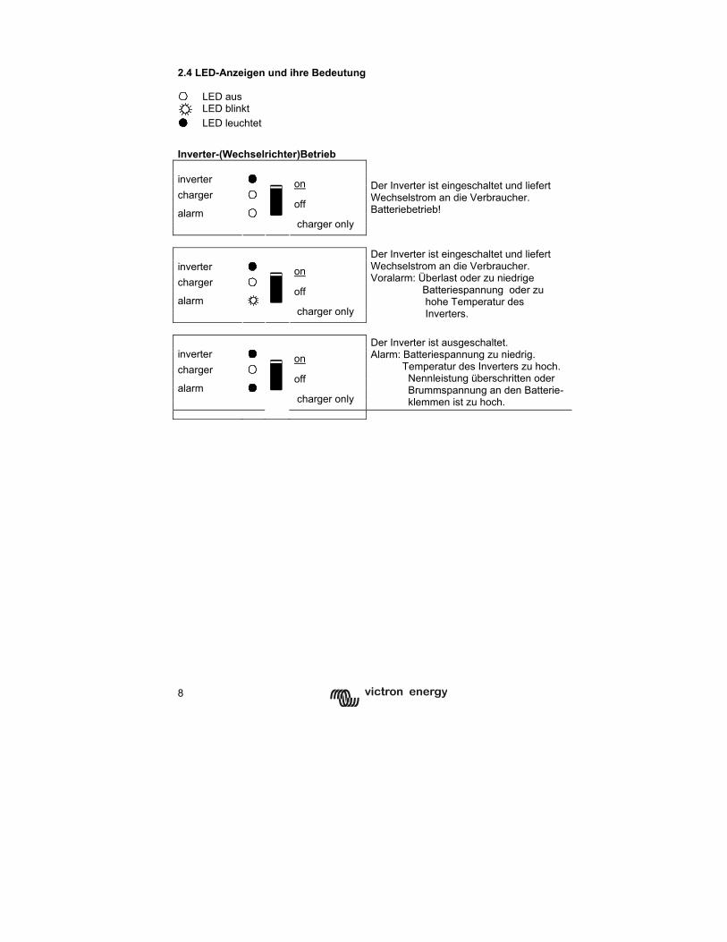
8
2.4 LED-Anzeigen und ihre Bedeutung LED aus
LED blinkt LED leuchtet
Inverter-(Wechselrichter)Betrieb inverter on charger off alarm
charger only
Der Inverter ist eingeschaltet und liefert Wechselstrom an die Verbraucher. Batteriebetrieb!
inverter on charger
off alarm
charger only
Der Inverter ist eingeschaltet und liefert Wechselstrom an die Verbraucher. Voralarm: Überlast oder zu niedrige Batteriespannung oder zu hohe Temperatur des Inverters.
inverter on charger
off alarm
charger only
Der Inverter ist ausgeschaltet. Alarm: Batteriespannung zu niedrig. Temperatur des Inverters zu hoch. Nennleistung überschritten oder Brummspannung an den Batterie- klemmen ist zu hoch.
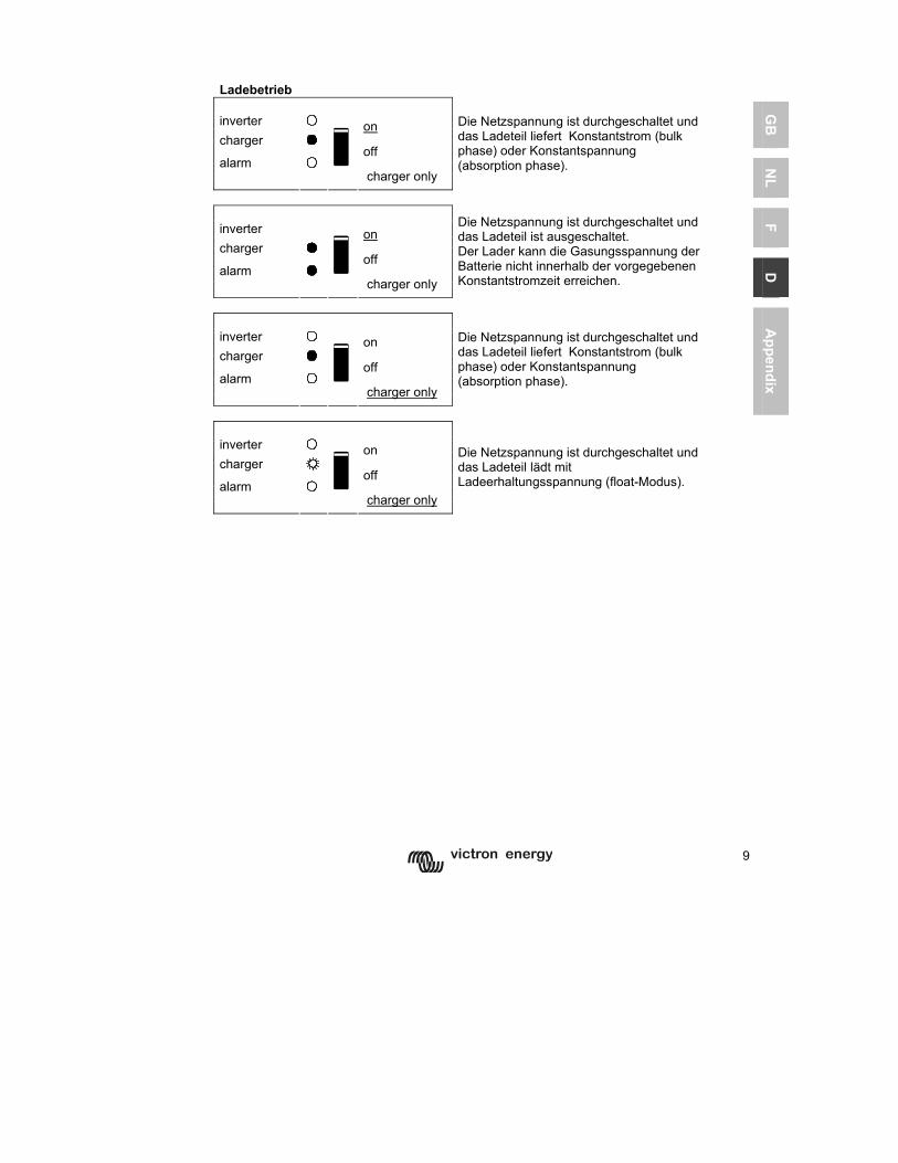
9
GB
N
L F
D
Appendix
Ladebetrieb inverter on charger off alarm
charger only
Die Netzspannung ist durchgeschaltet und das Ladeteil liefert Konstantstrom (bulk phase) oder Konstantspannung (absorption phase).
inverter on charger off alarm
charger only
Die Netzspannung ist durchgeschaltet und das Ladeteil ist ausgeschaltet. Der Lader kann die Gasungsspannung der Batterie nicht innerhalb der vorgegebenen Konstantstromzeit erreichen.
inverter on charger off alarm
charger only
Die Netzspannung ist durchgeschaltet und das Ladeteil liefert Konstantstrom (bulk phase) oder Konstantspannung (absorption phase).
inverter on charger off alarm
charger only
Die Netzspannung ist durchgeschaltet und das Ladeteil lädt mit Ladeerhaltungsspannung (float-Modus).
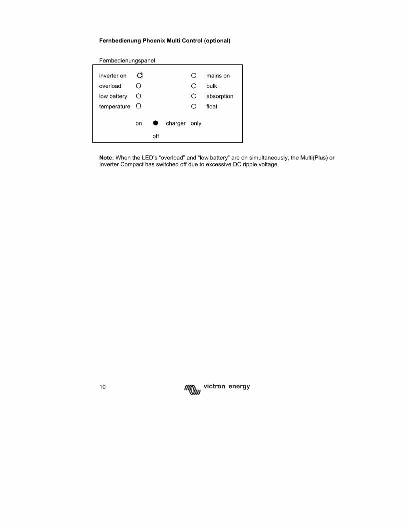
10
Fernbedienung Phoenix Multi Control (optional) Fernbedienungspanel inverter on mains on overload bulk
low battery absorption
temperature
float
on charger only
off
Note: When the LED’s “overload” and “low battery” are on simultaneously, the Multi(Plus) or Inverter Compact has switched off due to excessive DC ripple voltage.
11
GB
N
L F
D
Appendix
3 MONTAGE
Der Phoenix Multi Compact/Multi Plus Compact darf nur von einer qualifizierten Elektrofachkraft installiert werden.
3.1 Verpackungsinhalt Die Verpackung des Phoenix Multi Compact/Multi Plus Compact enthält folgende Einzelteile: Phoenix Multi Compact, Phoenix Multi Plus Compact oder Inverter Compact Bedienungsanleitung/Montageanleitung, Tüte mit Montagematerial: Befestigungsplatte Schrauben (5) Temperaturfühler, Aufkleber mit Warnhinweis für den Ladestrom. 3.2 Aufstellungsort Der Phoenix Multi Compact/MultiPlus Compact muss in einem trockenen, gut ventilierten Raum installiert werden, möglichst nahe an den Batterien. Zur besseren Kühlung muss um das Gerät 10 cm Luft gelassen werden.
Eine zu hohe Raumtemperatur kann folgende Auswirkungen haben: kürzere Lebensdauer, geringerer Ladestrom, geringere Spitzenleistung oder komplettes Abschalten des Inverters. Montieren Sie das Gerät niemals direkt über den Batterien.
Der Phoenix Multi Compact/MultiPlus Compact ist auch zur Wandmontage geeignet. Zum Befestigen des Geräts sind an der Rückseite des Gehäuses zwei Löcher angebracht. Siehe Anhang A. Das Gerät kann sowohl horizontal wie auch vertikal montiert werden. Allerdings sollte es, wenn möglich, vertikal montiert werden, da dies eine optimale Kühlung des Geräts gewährleistet.
Das Innere des Geräts muss nach der Installation noch gut zugänglich sein.
Sorgen Sie dafür, dass sowohl Netz- als auch die Batterie-Anschlusskabel über Sicherungen oder Leistungsschalter abgesichert sind. Um den Spannungsverlust über die Kabel möglichst gering zu halten, sollte der Abstand zwischen dem Gerät und der Batterie möglichst kurz sein.
Aus Sicherheitsgründen sollte dieses Gerät wie alle elektrischen Verbraucher, die eine bestimmte elektrische Leistung umsetzen, in einer hitzebeständigen Umgebung installiert werden. So sollten sich zum Beispiel Chemikalien, Kunststoffgegenstände, Gardinen oder andere Textilien usw. möglichst nicht in der direkten Umgebung befinden.
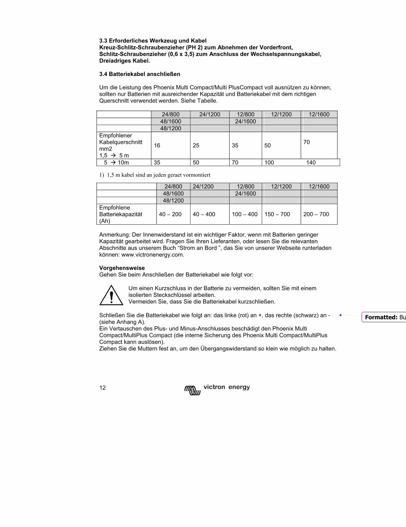
12
3.3 Erforderliches Werkzeug und Kabel Kreuz-Schlitz-Schraubenzieher (PH 2) zum Abnehmen der Vorderfront, Schlitz-Schraubenzieher (0,6 x 3,5) zum Anschluss der Wechselspannungskabel, Dreiadriges Kabel. 3.4 Batteriekabel anschließen Um die Leistung des Phoenix Multi Compact/Multi PlusCompact voll ausnützen zu können, sollten nur Batterien mit ausreichender Kapazität und Batteriekabel mit dem richtigen Querschnitt verwendet werden. Siehe Tabelle. 24/800 24/1200 12/800 12/1200 12/1600 48/1600 24/1600 48/1200 Empfohlener Kabelquerschnitt mm2 1,5 5 m
16 25 35 50
70
5 10m 35 50 70 100 140 1) 1,5 m kabel sind an jeden geraet vormontiert
24/800 24/1200 12/800 12/1200 12/1600 48/1600 24/1600 48/1200 Empfohlene Batteriekapazität (Ah)
40 – 200 40 – 400 100 – 400 150 – 700 200 – 700
Anmerkung: Der Innenwiderstand ist ein wichtiger Faktor, wenn mit Batterien geringer Kapazität gearbeitet wird. Fragen Sie Ihren Lieferanten, oder lesen Sie die relevanten Abschnitte aus unserem Buch “Strom an Bord ”, das Sie von unserer Webseite runterladen können: www.victronenergy.com. Vorgehensweise Gehen Sie beim Anschließen der Batteriekabel wie folgt vor:
Um einen Kurzschluss in der Batterie zu vermeiden, sollten Sie mit einem isolierten Steckschlüssel arbeiten. Vermeiden Sie, dass Sie die Batteriekabel kurzschließen.
Schließen Sie die Batteriekabel wie folgt an: das linke (rot) an +, das rechte (schwarz) an - (siehe Anhang A). Ein Vertauschen des Plus- und Minus-Anschlusses beschädigt den Phoenix Multi Compact/MultiPlus Compact (die interne Sicherung des Phoenix Multi Compact/MultiPlus Compact kann auslösen). Ziehen Sie die Muttern fest an, um den Übergangswiderstand so klein wie möglich zu halten.
Formatted: Bu
13
GB
N
L F
D
Appendix
3.5 Wechselstrom-Kabel anschließen
Dies ist ein Gerät der Sicherheitsklasse I (Gehäuse geerdet). Die Schutzerde an den Wechselstrom-Ein- und Ausgängen darf aus Sicherheitsgründen nicht unterbrochen werden. Alternativ kann der außenliegende Erdungspunkt am Gehäuse benutzt werden. Folgen Sie den Hinweisen:
a) Der Phoenix Inverter Compact arbeitet mit einem s.g. schwebenden Wechselstromausgang. Der außen am Gerät befindliche Erdanschlusspunkt muss geerdet werden. Der N-Leiter-Ausgang muss immer geerdet sein, damit ein Fehlerstrom-(FI)-Schutzschalter einwandfrei arbeiten kann.
b) Phoenix Multi/Multi Plus Compact : Der N-Leiter-Ausgang wird
automatisch mit dem Gehäuse verbunden (mithilfe des Erdungsrelais s. Anhang 2), wenn keine Netzspannung anliegt (Rückstromschutzrelais ist abgefallen, und das Gerät arbeitet im Inverter-Betrieb, s. Anhang 2). Liegt Netzspannung an, öffnet das Erdungsrelais, bevor das Rückstromschutzrelais schließt. Hat das Rückstromschutzrelais geschlossen, wird der geerdete N-Leiter des Netzes durchgeschaltet. Das gewährleistet ein sicheres Arbeiten des in den Wechselstromausgangskreis des Phoenix Multi Compact/MultiPlus Compact zu schaltenden Fehlerstrom-(FI)-Schalters.
- In einer Festinstallation (z.B. Hausinstallation) kann der unterbrechungsfreie Erdanschluss am Gerät durch den Erdleiter des Netzanschlusses gewährleistet werden.
- In einer ortsveränderlichen Installation (Netzanschluss über ein Landanschlusskabel) geht die Erdung verloren, wenn das Landanschlusskabel nicht eingesteckt ist. In diesem Fall muss das Gehäuse des Gerätes oder der an Bord befindliche Teil des Erdleiters vom Netzeingang am Chassis (eines Fahrzeugs) oder an der Erdungsplatte oder dem Rumpf (eines Bootes) angeschlossen werden.
- Marine-Anwendung: Aufgrund der Gefahr galvanischer Korrosion ist es eigentlich unerwünscht, die Landerde mit der Erdungsplatte oder dem Rumpf eines Bootes zu verbinden. Eine gute und sichere Lösung ist der Einbau eines Trenntrafos.
Der Netzeingangs- und Ausgangsanschluss mit den den Steckern G-ST18i befindet sich am Boden des Multi Compact (S. Anhang 1). Das Netz wird mit einem flexiblen Kabel 3 x 1,5 mm² (600VA) oder 3 x 2,5 mm² (1600VA) an den Stecker G-ST18i angeschlossen. Vorgehensweise Gehen Sie beim Anschließen der Kabel wie folgt vor: Das Kabel für den Wechselstromausgang kann direkt mithilfe der G-ST18i-Stecker angeschlossen werden. Die Anschlusspunkte sind deutlich gekennzeichnet. Von links nach rechts: "N" (Neutral) "PE" (Erde), und "L1" (Leiter).
14
Das Netzanschlusskabel kann direkt mit der G-ST18i-Anschlussdose angeschlossen werden. Die Anschlusspunkte sind deutlich gekennzeichnet. Von links nach rechts: „L1“ (Leiter), „PE“ (Erde) und „N“ (Neutral). Stecken Sie die Netzanschluss G-ST18i-Steckerdose in den Einbausteckereingang nächst der Rückfront. Stecken Sie den Wechselstromausgang Stecker in den Einbausteckdosen-Ausgang nächst der Vorderfront. 3.6 Weitere Anschlussmöglichkeiten Eine Reihe weiterer Anschlüsse ist möglich: Dazu die vier Schrauben der Frontpanels des Gehäuses lösen. 3.6.1 Starterbatterie Der Phoenix Multi Compact/Multi Plus Compact ist mit einem Anschluss zum Laden von Starterbatterien ausgestattet. Zum Anschließen siehe Anhang 1.
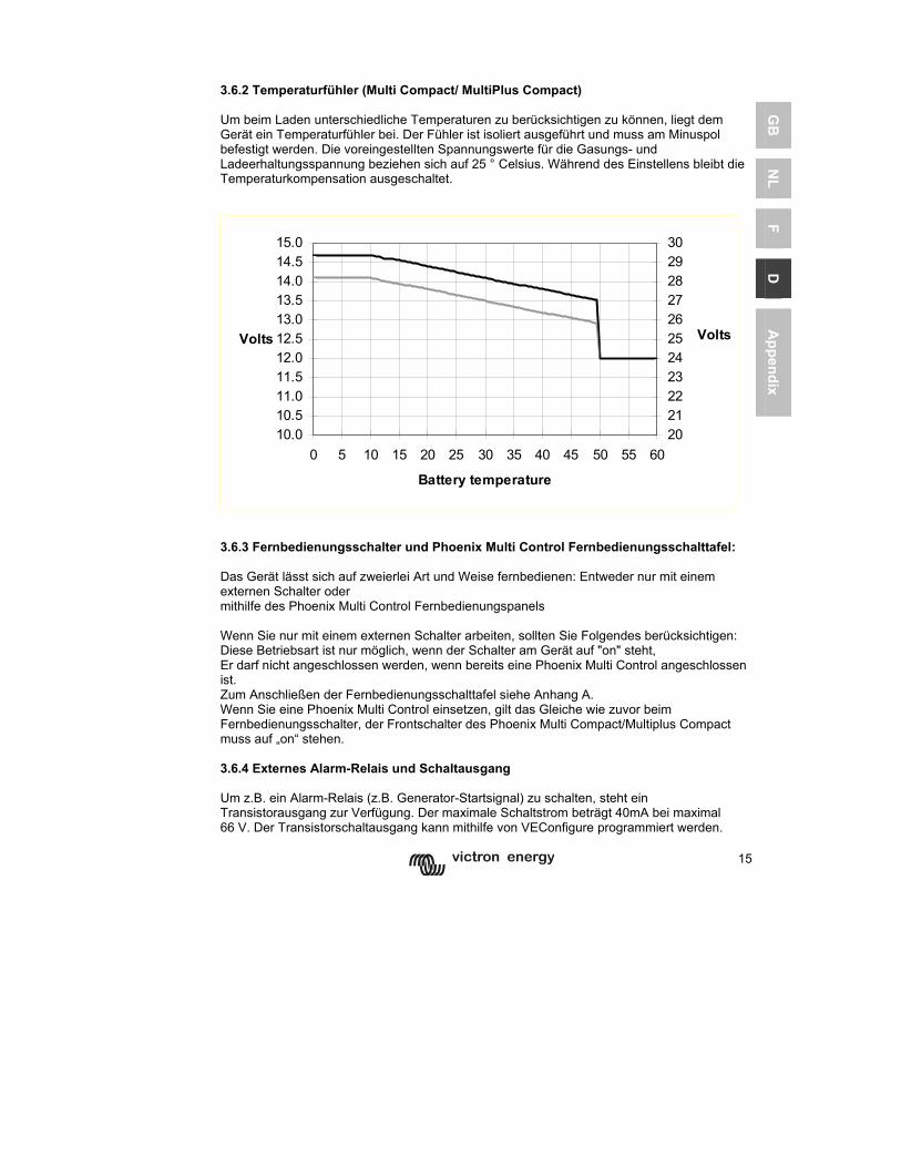
15
GB
N
L F
D
Appendix
3.6.2 Temperaturfühler (Multi Compact/ MultiPlus Compact) Um beim Laden unterschiedliche Temperaturen zu berücksichtigen zu können, liegt dem Gerät ein Temperaturfühler bei. Der Fühler ist isoliert ausgeführt und muss am Minuspol befestigt werden. Die voreingestellten Spannungswerte für die Gasungs- und Ladeerhaltungsspannung beziehen sich auf 25 ° Celsius. Während des Einstellens bleibt die Temperaturkompensation ausgeschaltet.
10.010.511.011.512.012.513.013.514.014.515.0
0 5 10 15 20 25 30 35 40 45 50 55 60
Battery temperature
Volts
2021222324252627282930
Volts
3.6.3 Fernbedienungsschalter und Phoenix Multi Control Fernbedienungsschalttafel: Das Gerät lässt sich auf zweierlei Art und Weise fernbedienen: Entweder nur mit einem externen Schalter oder mithilfe des Phoenix Multi Control Fernbedienungspanels Wenn Sie nur mit einem externen Schalter arbeiten, sollten Sie Folgendes berücksichtigen: Diese Betriebsart ist nur möglich, wenn der Schalter am Gerät auf "on" steht, Er darf nicht angeschlossen werden, wenn bereits eine Phoenix Multi Control angeschlossen ist. Zum Anschließen der Fernbedienungsschalttafel siehe Anhang A. Wenn Sie eine Phoenix Multi Control einsetzen, gilt das Gleiche wie zuvor beim Fernbedienungsschalter, der Frontschalter des Phoenix Multi Compact/Multiplus Compact muss auf „on“ stehen. 3.6.4 Externes Alarm-Relais und Schaltausgang Um z.B. ein Alarm-Relais (z.B. Generator-Startsignal) zu schalten, steht ein Transistorausgang zur Verfügung. Der maximale Schaltstrom beträgt 40mA bei maximal 66 V. Der Transistorschaltausgang kann mithilfe von VEConfigure programmiert werden.
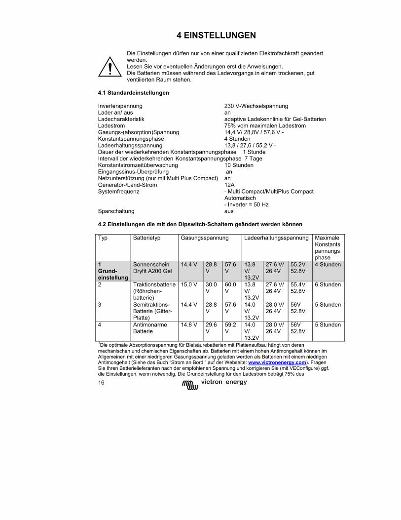
16
4 EINSTELLUNGEN
Die Einstellungen dürfen nur von einer qualifizierten Elektrofachkraft geändert werden. Lesen Sie vor eventuellen Änderungen erst die Anweisungen. Die Batterien müssen während des Ladevorgangs in einem trockenen, gut ventilierten Raum stehen.
4.1 Standardeinstellungen Inverterspannung 230 V-Wechselspannung Lader an/ aus an Ladecharakteristik adaptive Ladekennlinie für Gel-Batterien Ladestrom 75% vom maximalen Ladestrom Gasungs-(absorption)Spannung 14,4 V/ 28,8V / 57,6 V - Konstantspannungsphase 4 Stunden Ladeerhaltungsspannung 13,8 / 27,6 / 55,2 V - Dauer der wiederkehrenden Konstantspannungsphase 1 Stunde Intervall der wiederkehrenden Konstantspannungsphase 7 Tage Konstantstromzeitüberwachung 10 Stunden Eingangssinus-Überprüfung an Netzunterstützung (nur mit Multi Plus Compact) an Generator-/Land-Strom 12A Systemfrequenz - Multi Compact/MultiPlus Compact
Automatisch - Inverter = 50 Hz
Sparschaltung aus 4.2 Einstellungen die mit den Dipswitch-Schaltern geändert werden können Typ Batterietyp Gasungsspannung Ladeerhaltungsspannung Maximale
Konstantspannungsphase
1 Grund-einstellung
Sonnenschein Dryfit A200 Gel
14.4 V 28.8 V
57.6V
13.8 V/ 13.2V
27.6 V/ 26.4V
55.2V 52.8V
4 Stunden
2 Traktionsbatterie(Röhrchen-batterie)
15.0 V 30.0 V
60.0V
13.8 V/ 13.2V
27.6 V/ 26.4V
55.4V 52.8V
6 Stunden
3 Semitraktions-Batterie (Gitter-Platte)
14.4 V 28.8 V
57.6V
14.0 V/ 13.2V
28.0 V/ 26.4V
56V 52.8V
5 Stunden
4 Antimonarme Batterie
14.8 V 29.6 V
59.2V
14.0 V/ 13.2V
28.0 V/ 26.4V
56V 52.8V
5 Stunden
1Die optimale Absorptionsspannung für Bleisäurebatterien mit Plattenaufbau hängt von deren mechanischen und chemischen Eigenschaften ab. Batterien mit einem hohen Antimongehalt können im Allgemeinen mit einer niedrigeren Gasungsspannung geladen werden als Batterien mit einem niedrigen Antimongehalt (Siehe das Buch “Strom an Bord ” auf der Webseite: www.victronenergy.com). Fragen Sie Ihren Batterielieferanten nach der empfohlenen Spannung und korrigieren Sie (mit VEConfigure) ggf. die Einstellungen, wenn notwendig. Die Grundeinstellung für den Ladestrom beträgt 75% des
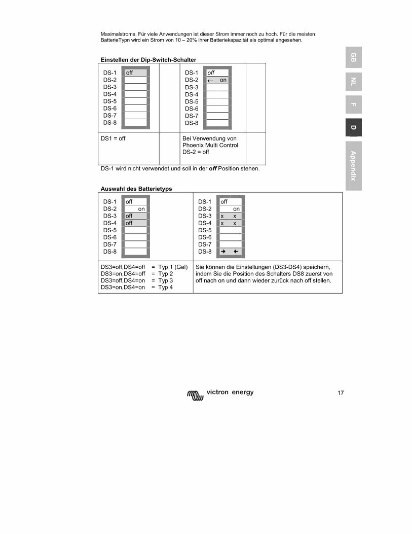
17
GB
N
L F
D
Appendix
Maximalstroms. Für viele Anwendungen ist dieser Strom immer noch zu hoch. Für die meisten BatterieTypn wird ein Strom von 10 – 20% ihrer Batteriekapazität als optimal angesehen. Einstellen der Dip-Switch-Schalter DS-1 off DS-2 DS-3 DS-4 DS-5 DS-6 DS-7 DS-8
DS-1 off DS-2 ← onDS-3 DS-4 DS-5 DS-6 DS-7 DS-8
DS1 = off
Bei Verwendung von Phoenix Multi Control DS-2 = off
DS-1 wird nicht verwendet und soll in der off Position stehen. Auswahl des Batterietyps DS-1 off DS-2 on DS-3 off DS-4 off DS-5 DS-6 DS-7 DS-8
DS-1 off DS-2 onDS-3 x x DS-4 x x DS-5 DS-6 DS-7 DS-8
DS3=off,DS4=off = Typ 1 (Gel) DS3=on,DS4=off = Typ 2 DS3=off,DS4=on = Typ 3 DS3=on,DS4=on = Typ 4
Sie können die Einstellungen (DS3-DS4) speichern, indem Sie die Position des Schalters DS8 zuerst von off nach on und dann wieder zurück nach off stellen.
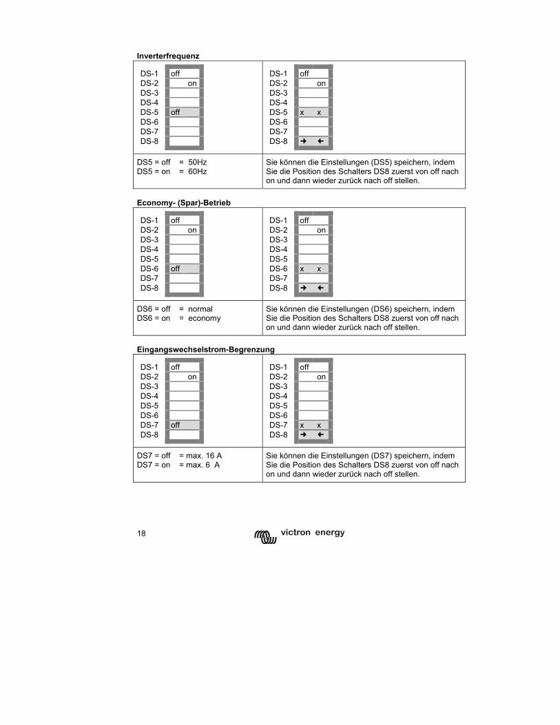
18
Inverterfrequenz DS-1 off DS-2 on DS-3 DS-4 DS-5 off DS-6 DS-7 DS-8
DS-1 off DS-2 onDS-3 DS-4 DS-5 x x DS-6 DS-7 DS-8
DS5 = off = 50Hz DS5 = on = 60Hz
Sie können die Einstellungen (DS5) speichern, indem Sie die Position des Schalters DS8 zuerst von off nach on und dann wieder zurück nach off stellen.
Economy- (Spar)-Betrieb DS-1 off DS-2 on DS-3 DS-4 DS-5 DS-6 off DS-7 DS-8
DS-1 off DS-2 onDS-3 DS-4 DS-5 DS-6 x x DS-7 DS-8
DS6 = off = normal DS6 = on = economy
Sie können die Einstellungen (DS6) speichern, indem Sie die Position des Schalters DS8 zuerst von off nach on und dann wieder zurück nach off stellen.
Eingangswechselstrom-Begrenzung DS-1 off DS-2 on DS-3 DS-4 DS-5 DS-6 DS-7 off DS-8
DS-1 off DS-2 onDS-3 DS-4 DS-5 DS-6 DS-7 x x DS-8
DS7 = off = max. 16 A DS7 = on = max. 6 A
Sie können die Einstellungen (DS7) speichern, indem Sie die Position des Schalters DS8 zuerst von off nach on und dann wieder zurück nach off stellen.
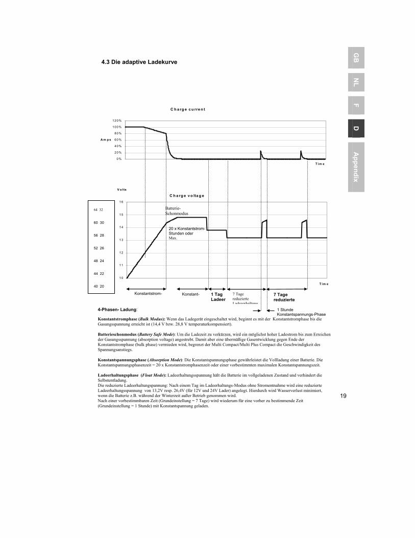
19
GB
N
L F
D
Appendix
4.3 Die adaptive Ladekurve
64 32
60 30 56 28
52 26
48 24
44 22 40 20
C h a rg e c u rre n t
0%
20%
40%
60%
80%
100%
120%
T im e
A m p s
C h a rg e v o lta g e
10
11
12
13
14
15
16
T im e
V o lts
4-Phasen- Ladung:
Konstantstromphase (Bulk Modus): Wenn das Ladegerät eingeschaltet wird, beginnt es mit der Konstantstromphase bis die Gasungsspannung erreicht ist (14,4 V bzw. 28,8 V temperaturkompensiert). Batterieschonmodus (Battery Safe Mode): Um die Ladezeit zu verkürzen, wird ein möglichst hoher Ladestrom bis zum Erreichen der Gasungsspannung (absorption voltage) angestrebt. Damit aber eine übermäßige Gasentwicklung gegen Ende der Konstantstromphase (bulk phase) vermieden wird, begrenzt der Multi Compact/Multi Plus Compact die Geschwindigkeit des Spannungsanstiegs. Konstantspannungsphase (Absorption Mode): Die Konstantspannungsphase gewährleistet die Vollladung einer Batterie. Die Konstantspannungsphasenzeit = 20 x Konstantstromphasenzeit oder einer vorbestimmten maximalen Konstantspannungszeit. Ladeerhaltungsphase (Float Mode): Ladeerhaltungsspannung hält die Batterie im vollgeladenen Zustand und verhindert die Selbstentladung. Die reduzierte Ladeerhaltungspannung: Nach einem Tag im Ladeerhaltungs-Modus ohne Stromentnahme wird eine reduzierte Ladeerhaltungsspannung von 13,2V resp. 26,4V (für 12V und 24V Lader) angelegt. Hierdurch wird Wasserverlust minimiert, wenn die Batterie z.B. während der Winterzeit außer Betrieb genommen wird. Nach einer vorbestimmbaren Zeit (Grundeinstellung = 7 Tage) wird wiederum für eine vorher zu bestimmende Zeit (Grundeinstellung = 1 Stunde) mit Konstantspannung geladen.
Konstantstrom- 1 Tag Ladeer
7 Tage reduzierte Ladeeerhaltung
Konstant-
1 Stunde Konstantspannungs-Phase
7 Tage reduzierte
20 x Konstantstrom-Stunden oder Max.
Batterie-Schonmodus
64 32 60 30 56 28 52 26 48 24 44 22 40 20
20
4.4 Einstellung des Ladeteils für Phoenix Multi Compact / MultiPlus Compact: 4.4.1 Vorprogrammierte Ladekennlinien: (können nur mit VEConfigure geändert werden) Lesen Sie in unserer Broschüre: „Strom an Bord“, die Sie auf unserer Webseite www.victronenergy.nl runterladen können, nach, wie Sie am besten Ihre Batterien laden können. Beim Phoenix Multi Compact/Multi Plus Compact haben Sie die Auswahl aus 3 vorprogrammierten Ladekennlinien. Festgelegte Ladekennlinie ist gekennzeichnet durch eine bestimmte (fest einstellbare) Zeit der Konstantspannungsphase. Nach der Konstantspannungsphase schaltet der Lader herunter auf die Ladeerhaltungsspannung. Um die Batterie „aufzufrischen“, schaltet der Lader periodisch zurück in die Konstantspannungsphase. Adaptive Ladekennlinie Die Zeitdauer für die Konstantspannungsphase ist abhängig von der Dauer der Konstantstromphase (s. 4.3.). Anschließend folgt die 24-stündige Ladeeerhaltungsphase, nach der mit verminderter Spannung von 0,8 V bzw. 1,6 V für 12 V bzw. 24V Batterien geladen wird. Wie bei der vorangegangenen festen Ladekennlinie schaltet der Lader periodisch zurück zur Konstantspannungsphase. Batterieschonmodus (Grundeinstellung) Um die Ladezeit zu verkürzen, wird ein möglichst hoher Ladestrom bis zum Erreichen der Gasungsspannung angestrebt. Damit aber eine übermäßige Gasentwicklung gegen Ende der Konstantstromphase vermieden wird, begrenzt der Phoenix Multi Compact/MultiPlus Compact die Geschwindigkeit des Spannungsanstiegs. 4.4.2 Weitere Einstellungen Konstantspannungszeit (Grundeinstellung: 4 Stunden) Die Konstantspannungsszeit-Einstellung legt die Zeit sowohl in der festgelegten Kennlinie als auch die der maximalen Zeit in der adaptiven Ladekennlinie fest. Die (maximale) Konstantspannungszeit kann zwischen 1 und 8 Stunden eingestellt werden. Die Ladeerhaltungsspannung (Grundeinstellung 14,4 V/28V) Die Ladeerhaltungsspannung kann zwischen 12-16V bzw. 24-32V in 0,05 V-Schritten eingestellt werden. Wiederkehrende Konstantspannungsphase Um die Batterie „aufzufrischen“, wird in der Ladeerhaltungsphase periodisch auf die Konstantspannung zurückgeschaltet, Wiederkehrende Konstantspannungszeit (Grundeinstellung = 1 Stunde) Die Konstantspannungszeit kann in Schritten von 1 bis 72 Viertelstunden eingestellt werden. Wiederkehrendes Konstantspannungszeitintervall (Grundeinstellung = 7 Tage) Das wiederkehrende Konstantspannungszeitintervall kann in Tagesschritten von 1 bis 45 eingestellt werden.
21
GB
N
L F
D
Appendix
4.5 Spezielle Einstellungen (kann nur mit VEConfigure geändert werden) Konstantstromzeitbegrenzung ein/aus (Grundeinstellung ein) Wenn der Lader nach 10 Stunden in der Konstantstromphase noch nicht die Gasungsspannung erreicht hat, kann es sein, dass die Batterie schon beschädigt ist. Um weitere Schäden zu verhindern, wird der Lader nach 10 Stunden Konstantstrom automatisch ausgeschaltet. In diesem Falle blinkt die gelbe LED-Anzeige. Netzeingangsspannungskontrolle (Grundeinstellung ein) Die Phoenix Multi Compact/MultiPlus Compact kontrolliert nicht nur die korrekte Spannungshöhe sondern auch die Sinus-Form der Eingangswechselspannnung. Arbeitet der Phoenix Multi Compact/MultiPlus Compact nicht richtig mit einem Generator, kann diese Funktion ausgeschaltet werden. Achtung: Wird die Netzeingangsspannungskontrolle ausgeschaltet, so wird auch die Abschaltung bei zu niedriger Eingangsspannung nicht wirksam, bis der Verbraucherstrom das 1,5-fache der Eingangsstrombegrenzung erreicht hat. Grund dafür ist, dass sich der Inverter nicht unnötig einschaltet, wenn ein großer Verbraucher eingeschaltet wird und die Eingangsspannung dadurch kurzzeitig einbricht. PowerControl – Arbeiten mit begrenzter Generatorleistung oder eingeschränktem Landstrom (nur Phoenix Multi Compact/ MultiPlus Compact) Der Phoenix Multi Compact/MultiPlus Compact verfügt über ein Batterieladegerät mit hoher Leistung. Deshalb zieht er eine Menge Strom vom Generator oder Landanschluss (fast 5 A am 230 V ∼ Netz). Mit dem Phoenix Multi Control kann der maximal zu entnehmende Netz- bzw. Generatorstrom eingestellt werden. Der Phoenix Multi Compact/Multi Plus Compact nimmt dann Rücksicht auf weitere angeschlossene Stromverbraucher und nutzt zum Laden nur den Strom, der noch „übrig“ ist. So wird verhindert, dass der Generator- oder der Landstromanschluss überlastet wird. Der Generator-/Landanschlussstrom kann zwischen 2 und 16 A eingestellt werden. Die Einstellungen am Phoenix Multi Control Panel überschreiben die internen Einstellungen. PowerAssist – „Leistungssteigerung“ von Generatoren und Landanschlussunterstützung Dieses Leistungsmerkmal unterscheidet den Phoenix Multi Plus Compact vom Multi Compact. Mit dieser Funktion erhält das Prinzip der Netzkontrolle eine neue Dimension, da der Multi Plus Compact jedes zu schwach ausgelegte Netz stützt. Damit kann, wenn hoher Strom für nur kurze Zeit benötigt wird, der Generator eine Nummer kleiner gewählt und ein eigentlich zu schwach ausgelegter Landstromanschluss gestützt werden. Wird die Last reduziert, d.h. werden Verbraucher ausgeschaltet, kann die dann wieder ausreichend vorhandene Energie zum Laden der Batterien genutzt werden. Hinweis 1: Um die Funktion „PowerAssist“ nutzen zu können, benötigt ein Phoenix MultiPlus Compact einen Mindeststrom von 2 A – sei es vom Landanschluss oder vom Generator. Hinweis 2 : Einige Generatoren der neuen Generation erzeugen ihren Ausgangswechselstrom über einen statischen Inverter. Weiter reduzieren einige dieser Generatoren ihre Drehzahl, wenn nur kleine Verbraucher angeschlossen sind. Durch Ausschalten der „Dynamic Limit Function“ (VEConfigure) kann der MultiPlus Compact den Generator stützen, wenn plötzlich große Verbraucher eingeschaltet werden.
22
Externes Alarm-Relais und Schaltausgang (Grundeinstellung: aus) Um z.B. ein Alarm-Relais (z.B. Generator-Startsignal) zu schalten, steht ein Transistorausgang zur Verfügung Der maximale Schaltstrom beträgt 40mA bei maximal 66 V. Der Transistorschaltausgang kann mithilfe von VEConfigure programmiert werden. 4.6 Wartung Für den Phoenix Multi Compact ist keine spezielle Wartung erforderlich. Es genügt völlig, wenn alle Anschlüsse einmal pro Jahr kontrolliert werden. Schützen Sie den Phoenix Multi Compact/MultiPlus Compact vor Schmutz und Nässe.
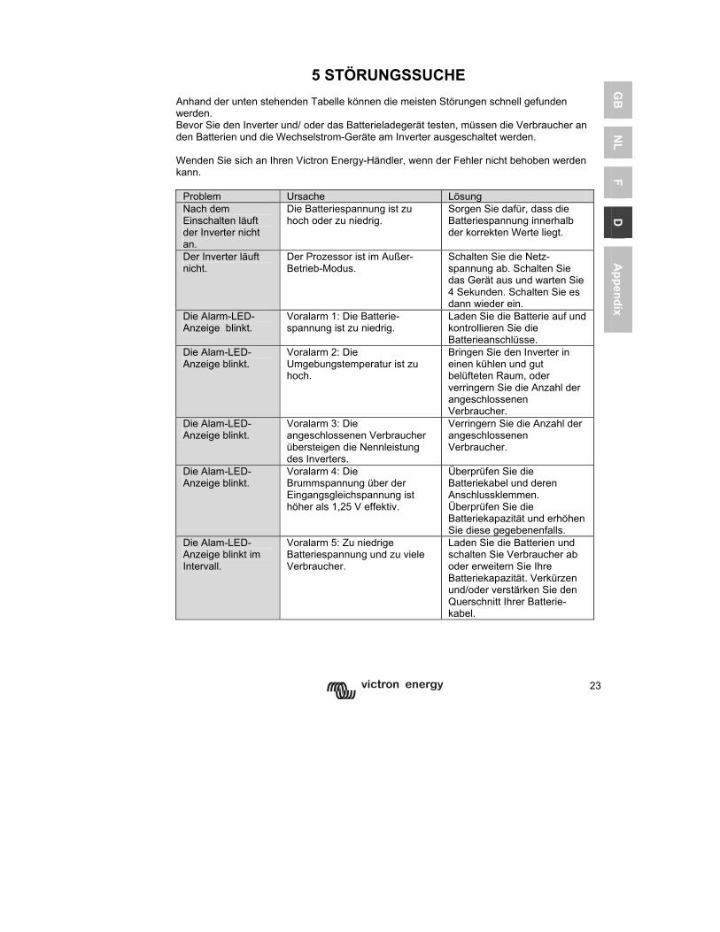
23
GB
N
L F
D
Appendix
5 STÖRUNGSSUCHE
Anhand der unten stehenden Tabelle können die meisten Störungen schnell gefunden werden. Bevor Sie den Inverter und/ oder das Batterieladegerät testen, müssen die Verbraucher an den Batterien und die Wechselstrom-Geräte am Inverter ausgeschaltet werden. Wenden Sie sich an Ihren Victron Energy-Händler, wenn der Fehler nicht behoben werden kann.
Problem Ursache Lösung Nach dem Einschalten läuft der Inverter nicht an.
Die Batteriespannung ist zu hoch oder zu niedrig.
Sorgen Sie dafür, dass die Batteriespannung innerhalb der korrekten Werte liegt.
Der Inverter läuft nicht.
Der Prozessor ist im Außer-Betrieb-Modus.
Schalten Sie die Netz-spannung ab. Schalten Sie das Gerät aus und warten Sie 4 Sekunden. Schalten Sie es dann wieder ein.
Die Alarm-LED-Anzeige blinkt.
Voralarm 1: Die Batterie-spannung ist zu niedrig.
Laden Sie die Batterie auf und kontrollieren Sie die Batterieanschlüsse.
Die Alam-LED-Anzeige blinkt.
Voralarm 2: Die Umgebungstemperatur ist zu hoch.
Bringen Sie den Inverter in einen kühlen und gut belüfteten Raum, oder verringern Sie die Anzahl der angeschlossenen Verbraucher.
Die Alam-LED-Anzeige blinkt.
Voralarm 3: Die angeschlossenen Verbraucher übersteigen die Nennleistung des Inverters.
Verringern Sie die Anzahl der angeschlossenen Verbraucher.
Die Alam-LED-Anzeige blinkt.
Voralarm 4: Die Brummspannung über der Eingangsgleichspannung ist höher als 1,25 V effektiv.
Überprüfen Sie die Batteriekabel und deren Anschlussklemmen. Überprüfen Sie die Batteriekapazität und erhöhen Sie diese gegebenenfalls.
Die Alam-LED-Anzeige blinkt im Intervall.
Voralarm 5: Zu niedrige Batteriespannung und zu viele Verbraucher.
Laden Sie die Batterien und schalten Sie Verbraucher ab oder erweitern Sie Ihre Batteriekapazität. Verkürzen und/oder verstärken Sie den Querschnitt Ihrer Batterie-kabel.
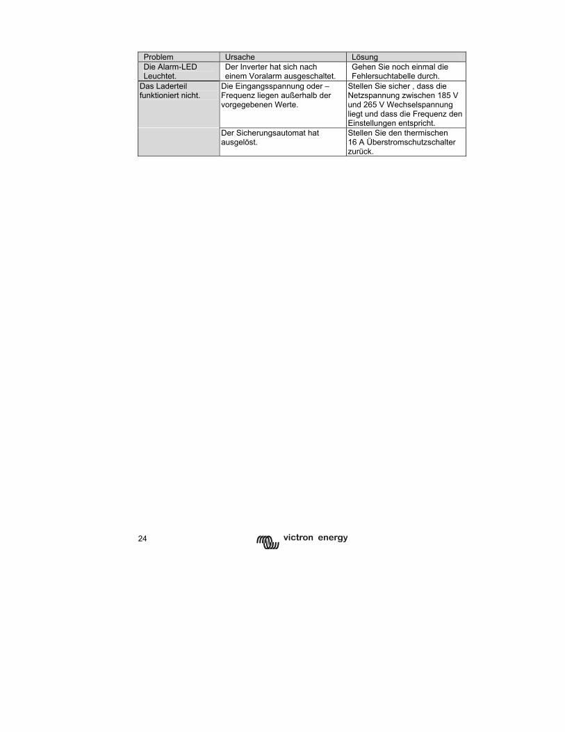
24
Problem Ursache Lösung Die Alarm-LED Leuchtet.
Der Inverter hat sich nach einem Voralarm ausgeschaltet.
Gehen Sie noch einmal die Fehlersuchtabelle durch.
Das Laderteil funktioniert nicht.
Die Eingangsspannung oder –Frequenz liegen außerhalb der vorgegebenen Werte.
Stellen Sie sicher , dass die Netzspannung zwischen 185 V und 265 V Wechselspannung liegt und dass die Frequenz den Einstellungen entspricht.
Der Sicherungsautomat hat ausgelöst.
Stellen Sie den thermischen 16 A Überstromschutzschalter zurück.
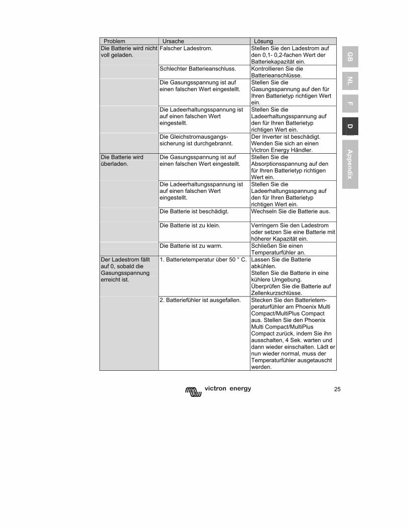
25
GB
N
L F
D
Appendix
Problem Ursache Lösung
Die Batterie wird nicht voll geladen.
Falscher Ladestrom. Stellen Sie den Ladestrom auf den 0,1- 0,2-fachen Wert der Batteriekapazität ein.
Schlechter Batterieanschluss.
Kontrollieren Sie die Batterieanschlüsse.
Die Gasungsspannung ist auf einen falschen Wert eingestellt.
Stellen Sie die Gasungsspannung auf den für Ihren Batterietyp richtigen Wert ein.
Die Ladeerhaltungsspannung ist auf einen falschen Wert eingestellt.
Stellen Sie die Ladeerhaltungsspannung auf den für Ihren Batterietyp richtigen Wert ein.
Die Gleichstromausgangs-sicherung ist durchgebrannt.
Der Inverter ist beschädigt. Wenden Sie sich an einen Victron Energy Händler.
Die Batterie wird überladen.
Die Gasungsspannung ist auf einen falschen Wert eingestellt.
Stellen Sie die Absorptionsspannung auf den für Ihren Batterietyp richtigen Wert ein.
Die Ladeerhaltungsspannung ist auf einen falschen Wert eingestellt.
Stellen Sie die Ladeerhaltungsspannung auf den für Ihren Batterietyp richtigen Wert ein.
Die Batterie ist beschädigt. Wechseln Sie die Batterie aus.
Die Batterie ist zu klein. Verringern Sie den Ladestrom oder setzen Sie eine Batterie mit höherer Kapazität ein.
Die Batterie ist zu warm. Schließen Sie einen Temperaturfühler an.
Der Ladestrom fällt auf 0, sobald die Gasungsspannung erreicht ist.
1. Batterietemperatur über 50 ° C. Lassen Sie die Batterie abkühlen. Stellen Sie die Batterie in eine kühlere Umgebung. Überprüfen Sie die Batterie auf Zellenkurzschlüsse.
2. Batteriefühler ist ausgefallen. Stecken Sie den Batterietem-peraturfühler am Phoenix Multi Compact/MultiPlus Compact aus. Stellen Sie den Phoenix Multi Compact/MultiPlus Compact zurück, indem Sie ihn ausschalten, 4 Sek. warten und dann wieder einschalten. Lädt er nun wieder normal, muss der Temperaturfühler ausgetauscht werden.
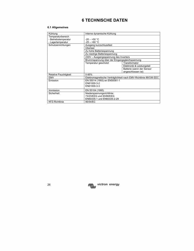
26
6 TECHNISCHE DATEN
6.1 Allgemeines Kühlung Interne dynamische Kühlung Temperaturbereich - Betriebstemperatur - Lagertemperatur
-20 – +50 °C -25 – +60 °C Ausgang kurzschlussfest Überlast Zu hohe Batteriespannung Zu niedrige Batteriespannung 230V ∼ Ausgangsspannung des Inverters Brummspannung über der Eingangsgleichspannung
Transformator Elektronik & Leistungsteil
Schutzeinrichtungen
Temperatur geschützt
Batterie (wenn der Sensor angeschlossen ist)
Relative Feuchtigkeit 0-95% EMV Elektromagnetische Verträglichkeit nach EMV-Richtlinie 89/336 EECEmission EN 55014 (1993) en EN50081-1
EN61000-3-2 EN61000-3-3
Immission EN 55104 (1995) Sicherheit Niederspannungsrichtlinie:
73/23/EEG und 93/68/EEG EN60335-1 und EN60335-2-29
KFZ-Richtlinie 95/54/EC
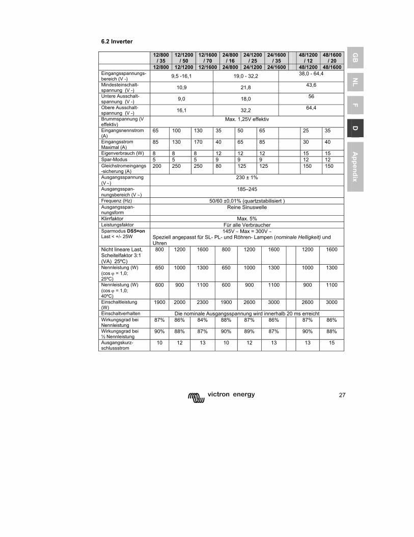
27
GB
N
L F
D
Appendix
6.2 Inverter 12/800
/ 35 12/1200
/ 50 12/1600
/ 70 24/800
/ 16 24/1200
/ 25 24/1600
/ 35
48/1200 / 12
48/1600/ 20
12/800 12/1200 12/1600 24/800 24/1200 24/1600 48/1200 48/1600Eingangsspannungs-bereich (V -) 9,5 -16,1 19,0 - 32,2 38,0 - 64,4
Mindesteinschalt-spannung (V -) 10,9 21,8 43,6
Untere Ausschalt-spannung (V -) 9,0 18,0 56
Obere Ausschalt-spannung (V -) 16,1 32,2 64,4
Brummspannung (V effektiv)
Max. 1,25V effektiv
Eingangsnennstrom (A)
65 100 130 35 50 65 25 35
Eingangsstrom Maximal (A)
85 130 170 40 65 85 30 40
Eigenverbrauch (W) 8 8 8 12 12 12 15 15 Spar-Modus 5 5 5 9 9 9 12 12 Gleichstromeingangs-sicherung (A)
200 250 250 80 125 125 150 150
Ausgangsspannung (V ∼)
230 ± 1%
Ausgangsspan-nungsbereich (V ∼)
185–245
Frequenz (Hz) 50/60 ±0,01% (quartzstabilisiert ) Ausgangsspan-nungsform
Reine Sinuswelle
Klirrfaktor Max. 5% Leistungsfaktor Für alle Verbraucher Sparmodus DS5=on Last < +/- 25W
145V ∼ Max = 300V ∼ Speziell angepasst für SL- PL- und Röhren- Lampen (nominale Helligkeit) und Uhren
Nicht lineare Last, Scheitelfaktor 3:1 (VA) 25ºC)
800 1200 1600 800 1200 1600 1200 1600
Nennleistung (W) (cos ϕ = 1,0; 25ºC)
650 1000 1300 650 1000 1300 1000 1300
Nennleistung (W) (cos ϕ = 1,0; 40ºC)
600 900 1100 600 900 1100 900 1100
Einschaltleistung (W)
1900 2000 2300 1900 2600 3000 2600 3000
Einschaltverhalten Die nominale Ausgangsspannung wird innerhalb 20 ms erreicht Wirkungsgrad bei Nennleistung
87% 86% 84% 88% 87% 86% 87% 86%
Wirkungsgrad bei ½ Nennleistung
90% 88% 87% 90% 89% 87% 90% 88%
Ausgangskurz-schlussstrom
10 12 13 10 12 13 13 15
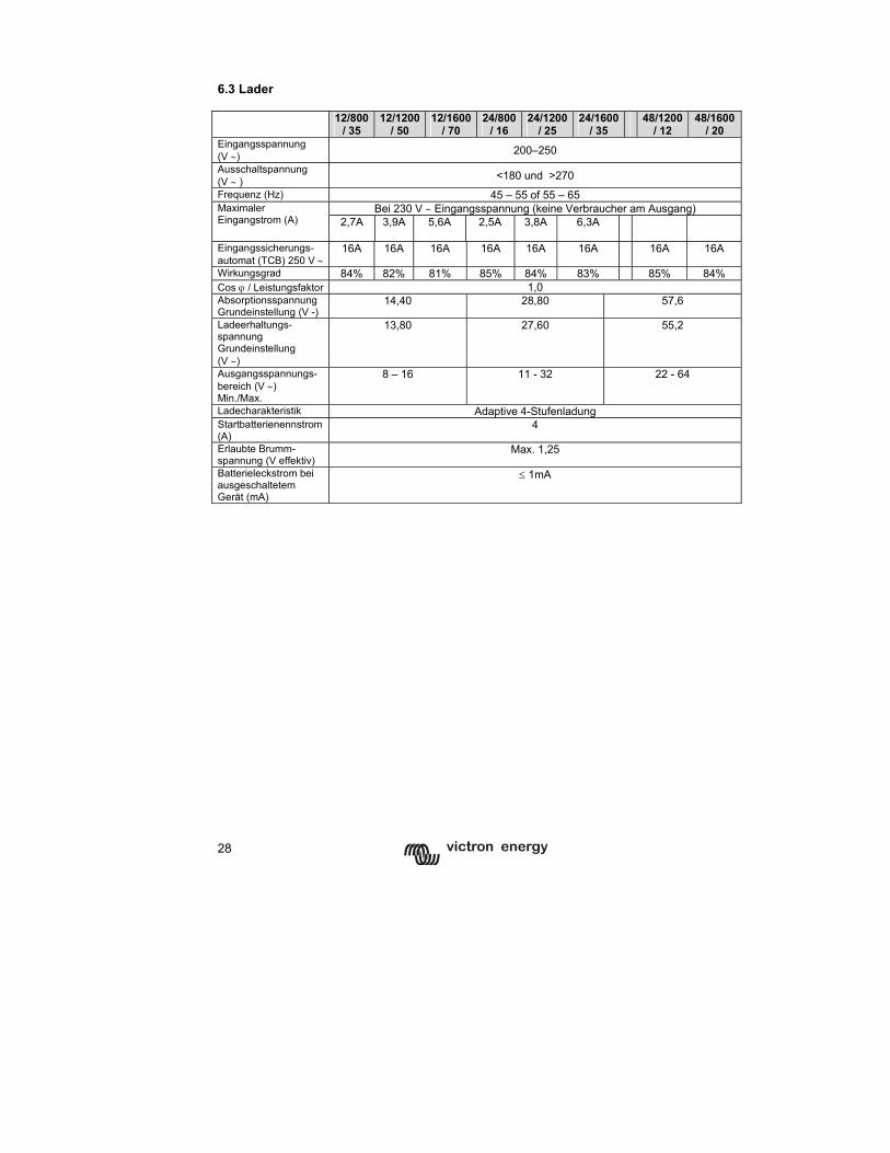
28
6.3 Lader 12/800
/ 35 12/1200
/ 50 12/1600
/ 70 24/800
/ 16 24/1200
/ 25 24/1600
/ 35
48/1200 / 12
48/1600/ 20
Eingangsspannung (V ∼) 200–250
Ausschaltspannung (V ∼ ) <180 und >270
Frequenz (Hz) 45 – 55 of 55 – 65 Bei 230 V ∼ Eingangsspannung (keine Verbraucher am Ausgang) Maximaler
Eingangstrom (A) 2,7A 3,9A 5,6A
2,5A 3,8A 6,3A
Eingangssicherungs-automat (TCB) 250 V ∼
16A 16A 16A 16A 16A 16A 16A 16A
Wirkungsgrad 84% 82% 81% 85% 84% 83% 85% 84% Cos ϕ / Leistungsfaktor 1,0 Absorptionsspannung Grundeinstellung (V -)
14,40 28,80 57,6
Ladeerhaltungs-spannung Grundeinstellung (V ∼)
13,80 27,60 55,2
Ausgangsspannungs-bereich (V ∼) Min./Max.
8 – 16 11 - 32 22 - 64
Ladecharakteristik Adaptive 4-Stufenladung Startbatterienennstrom (A)
4
Erlaubte Brumm-spannung (V effektiv)
Max. 1,25
Batterieleckstrom bei ausgeschaltetem Gerät (mA)
≤ 1mA
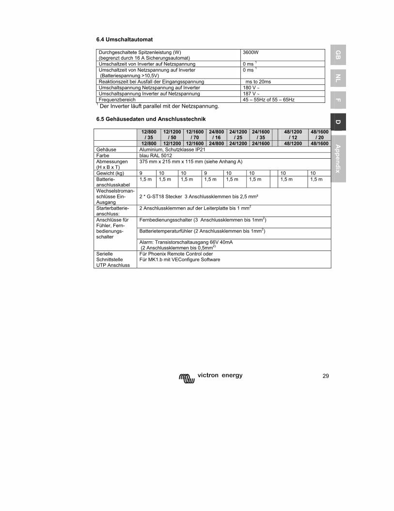
29
GB
N
L F
D
Appendix
6.4 Umschaltautomat Durchgeschaltete Spitzenleistung (W) (begrenzt durch 16 A Sicherungsautomat)
3600W
Umschaltzeit von Inverter auf Netzspannung 0 ms 1 Umschaltzeit von Netzspannung auf Inverter (Batteriespannung >10,5V)
0 ms 1
Reaktionszeit bei Ausfall der Eingangsspannung ms to 20ms Umschaltspannung Netzspannung auf Inverter 180 V ∼ Umschaltspannung Inverter auf Netzspannung 187 V ∼ Frequenzbereich 45 – 55Hz of 55 – 65Hz
1 Der Inverter läuft parallel mit der Netzspannung. 6.5 Gehäusedaten und Anschlusstechnik 12/800
/ 35 12/1200
/ 50 12/1600
/ 70 24/800
/ 16 24/1200
/ 25 24/1600
/ 35 48/1200
/ 12 48/1600
/ 20 12/800 12/1200 12/1600 24/800 24/1200 24/1600 48/1200 48/1600Gehäuse Aluminium, Schutzklasse IP21 Farbe blau RAL 5012 Abmessungen (H x B x T)
375 mm x 215 mm x 115 mm (siehe Anhang A)
Gewicht (kg) 9 10 10 9 10 10 10 10 Batterie-anschlusskabel
1,5 m 1,5 m 1,5 m 1,5 m 1,5 m 1,5 m 1,5 m 1,5 m
Wechselstroman-schlüsse Ein- Ausgang
2 * G-ST18 Stecker 3 Anschlussklemmen bis 2,5 mm²
Starterbatterie-anschluss:
2 Anschlussklemmen auf der Leiterplatte bis 1 mm2
Fernbedienungsschalter (3 Anschlussklemmen bis 1mm2)
Batterietemperaturfühler (2 Anschlussklemmen bis 1mm2)
Anschlüsse für Fühler, Fern-bedienungs-schalter
Alarm: Transistorschaltausgang 66V 40mA (2 Anschlussklemmen bis 0,5mm2)
Serielle Schnittstelle UTP Anschluss
Für Phoenix Remote Control oder Für MK1.b mit VEConfigure Software

30
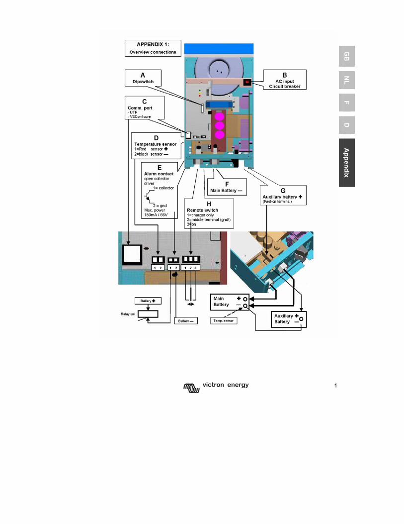
1
GB
N
L F
D
Appendix
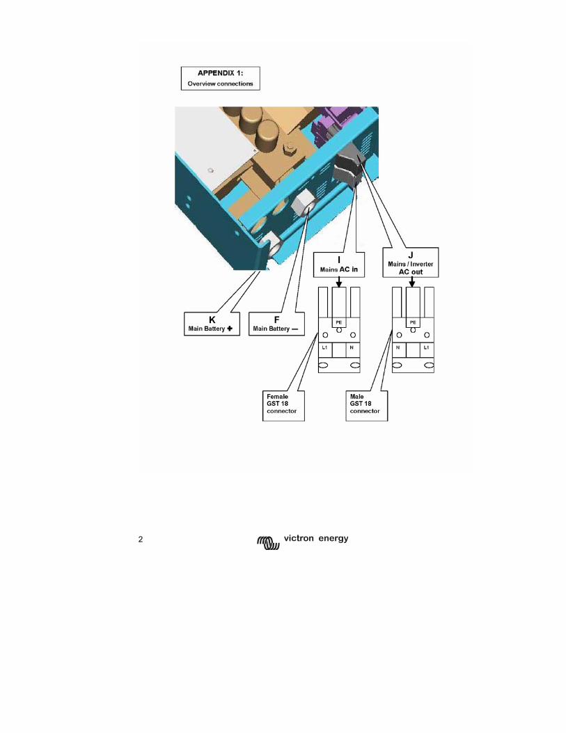
2
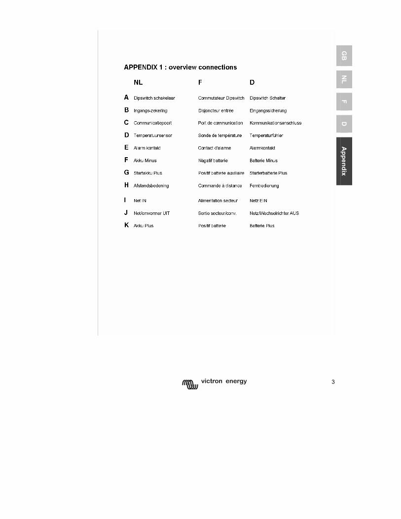
3
GB
N
L F
D
Appendix
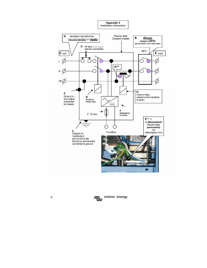
4
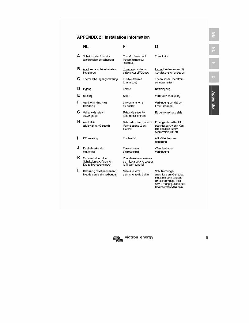
5
GB
N
L F
D
Appendix
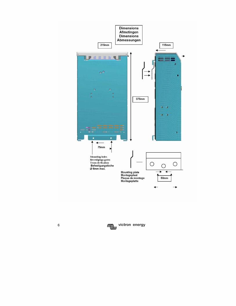
6
7
GB
N
L F
D
Appendix

Serial number:
Distributor:
Victron Energy B.V. The Netherlands
General phone: +31 (0)36 535 97 00 Customer support desk: +31 (0)36 535 97 77 General and Service fax: +31 (0)36 531 16 66 Sales fax: +31 (0)36 535 97 40 E-mail: [email protected] Internet site: http://www.victronenergy.com Article number: ISM001003000 Version: 04 Date: 14-01-2005