Embed Size (px)
Citation preview
IM1052WN 04/13
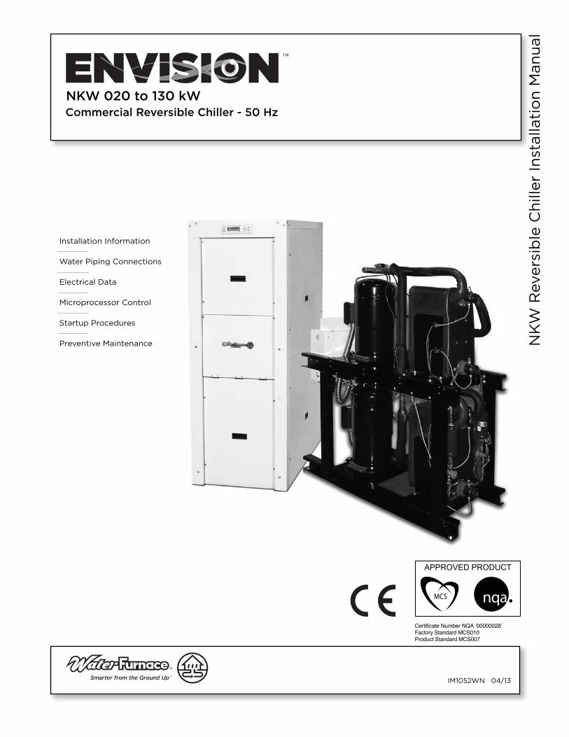
Installation Information
Water Piping Connections
Electrical Data
Microprocessor Control
Startup Procedures
Preventive Maintenance NK
W R
evers
ible
Ch
iller
Inst
alla
tio
n M
an
ual
Commercial Reversible Chiller - 50 Hz
NKW 020 to 130 kW
Certi cate Number NQA ‘00000028’Factory Standard MCS010Product Standard MCS007

NKW REVERSIBLE CHILLER INSTALLATION MANUAL
Table of ContentsModel Nomenclature. . . . . . . . . . . . . . . . . . . . . . . . . . . . . . . . . . . . . . . . . . . . . . . . . . . . . . . . . . . 4
BS EN 14511-2 Performance Ratings . . . . . . . . . . . . . . . . . . . . . . . . . . . . . . . . . . . . . . . . . . . . . . 5
Legend . . . . . . . . . . . . . . . . . . . . . . . . . . . . . . . . . . . . . . . . . . . . . . . . . . . . . . . . . . . . . . . . . . . . . . 5
General Installation Information . . . . . . . . . . . . . . . . . . . . . . . . . . . . . . . . . . . . . . . . . . . . . . . .6-7
NKW Features . . . . . . . . . . . . . . . . . . . . . . . . . . . . . . . . . . . . . . . . . . . . . . . . . . . . . . . . . . . . . . . . 8
Physical Dimensions . . . . . . . . . . . . . . . . . . . . . . . . . . . . . . . . . . . . . . . . . . . . . . . . . . . . . . . . . . . 9
Physical Data . . . . . . . . . . . . . . . . . . . . . . . . . . . . . . . . . . . . . . . . . . . . . . . . . . . . . . . . . . . . . . . . .10
Field Connected Water Piping . . . . . . . . . . . . . . . . . . . . . . . . . . . . . . . . . . . . . . . . . . . . . . . .11-12
Water Quality . . . . . . . . . . . . . . . . . . . . . . . . . . . . . . . . . . . . . . . . . . . . . . . . . . . . . . . . . . . . . . . . . 13
System Cleaning and Flushing. . . . . . . . . . . . . . . . . . . . . . . . . . . . . . . . . . . . . . . . . . . . . . . . . . .14
Electrical Data . . . . . . . . . . . . . . . . . . . . . . . . . . . . . . . . . . . . . . . . . . . . . . . . . . . . . . . . . . . . . . . . 15
Wiring Schematic . . . . . . . . . . . . . . . . . . . . . . . . . . . . . . . . . . . . . . . . . . . . . . . . . . . . . . . . . . 16-17
Field Wiring and Control Setup. . . . . . . . . . . . . . . . . . . . . . . . . . . . . . . . . . . . . . . . . . . . . . . 18-19
Unit Startup . . . . . . . . . . . . . . . . . . . . . . . . . . . . . . . . . . . . . . . . . . . . . . . . . . . . . . . . . . . . . . . . . 20
Envision Controls - FX10 . . . . . . . . . . . . . . . . . . . . . . . . . . . . . . . . . . . . . . . . . . . . . . . . . . . . 21-25
Sequence of Operation. . . . . . . . . . . . . . . . . . . . . . . . . . . . . . . . . . . . . . . . . . . . . . . . . . . . . . . . 26
Inputs and Outputs Configuration . . . . . . . . . . . . . . . . . . . . . . . . . . . . . . . . . . . . . . . . . . . . . . 27
Networking Protocol. . . . . . . . . . . . . . . . . . . . . . . . . . . . . . . . . . . . . . . . . . . . . . . . . . . . . . . . . . 27
Unit Display and Interface . . . . . . . . . . . . . . . . . . . . . . . . . . . . . . . . . . . . . . . . . . . . . . . . . . 28-30
Reference Calculations . . . . . . . . . . . . . . . . . . . . . . . . . . . . . . . . . . . . . . . . . . . . . . . . . . . . . . . . .31
Operating Parameters. . . . . . . . . . . . . . . . . . . . . . . . . . . . . . . . . . . . . . . . . . . . . . . . . . . . . . . . . .31
Pressure Drop. . . . . . . . . . . . . . . . . . . . . . . . . . . . . . . . . . . . . . . . . . . . . . . . . . . . . . . . . . . . . . . . 32
Compressor Resistance . . . . . . . . . . . . . . . . . . . . . . . . . . . . . . . . . . . . . . . . . . . . . . . . . . . . . . . 32
Heat of Extraction/Rejection Data . . . . . . . . . . . . . . . . . . . . . . . . . . . . . . . . . . . . . . . . . . . . . . 33
Heating and Cooling Cycle Analysis . . . . . . . . . . . . . . . . . . . . . . . . . . . . . . . . . . . . . . . . . . . . . 34
Startup and Troubleshooting Form . . . . . . . . . . . . . . . . . . . . . . . . . . . . . . . . . . . . . . . . . . . . . 35
Troubleshooting. . . . . . . . . . . . . . . . . . . . . . . . . . . . . . . . . . . . . . . . . . . . . . . . . . . . . . . . . . . . . . 36
Preventive Maintenance . . . . . . . . . . . . . . . . . . . . . . . . . . . . . . . . . . . . . . . . . . . . . . . . . . . . . . . 37
Service Parts List . . . . . . . . . . . . . . . . . . . . . . . . . . . . . . . . . . . . . . . . . . . . . . . . . . . . . . . . . . . . . 38
Revision Guide . . . . . . . . . . . . . . . . . . . . . . . . . . . . . . . . . . . . . . . . . . . . . . . . . . . . . . . . . . . . . . . 39
4
NKW REVERSIBLE CHILLER INSTALLATION MANUAL
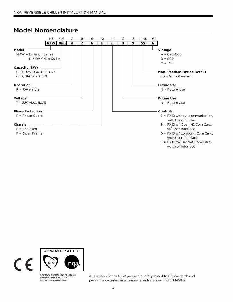
All Envision Series NKW product is safety tested to CE standards and performance tested in accordance with standard BS EN 14511-2.
Model Nomenclature1-3 4-6 7 8 9 10 11 12 13 14-15 16
NKW 060 R 7 P F 8 N N SS A
Model NKW = Envision Series
R-410A Chiller 50 Hz
Capacity (kW) 020, 025, 030, 035, 045,
050, 060, 090, 130
Operation R = Reversible
Voltage 7 = 380-420/50/3
Phase Protection P = Phase Guard
Chassis E = Enclosed
F = Open Frame
Vintage A = 020-060
B = 090
C = 130
Non-Standard Option Details SS = Non-Standard
Future Use N = Future Use
Future Use N = Future Use
Controls 8 = FX10 without communication,
with User Interface
9 = FX10 w/ Open N2 Com Card,
w/ User Interface
0 = FX10 w/ Lonworks Com Card,
with User Interface
3 = FX10 w/ BacNet Com Card,
w/ User Interface
Certi cate Number NQA ‘00000028’Factory Standard MCS010Product Standard MCS007
5
NKW REVERSIBLE CHILLER INSTALLATION MANUAL
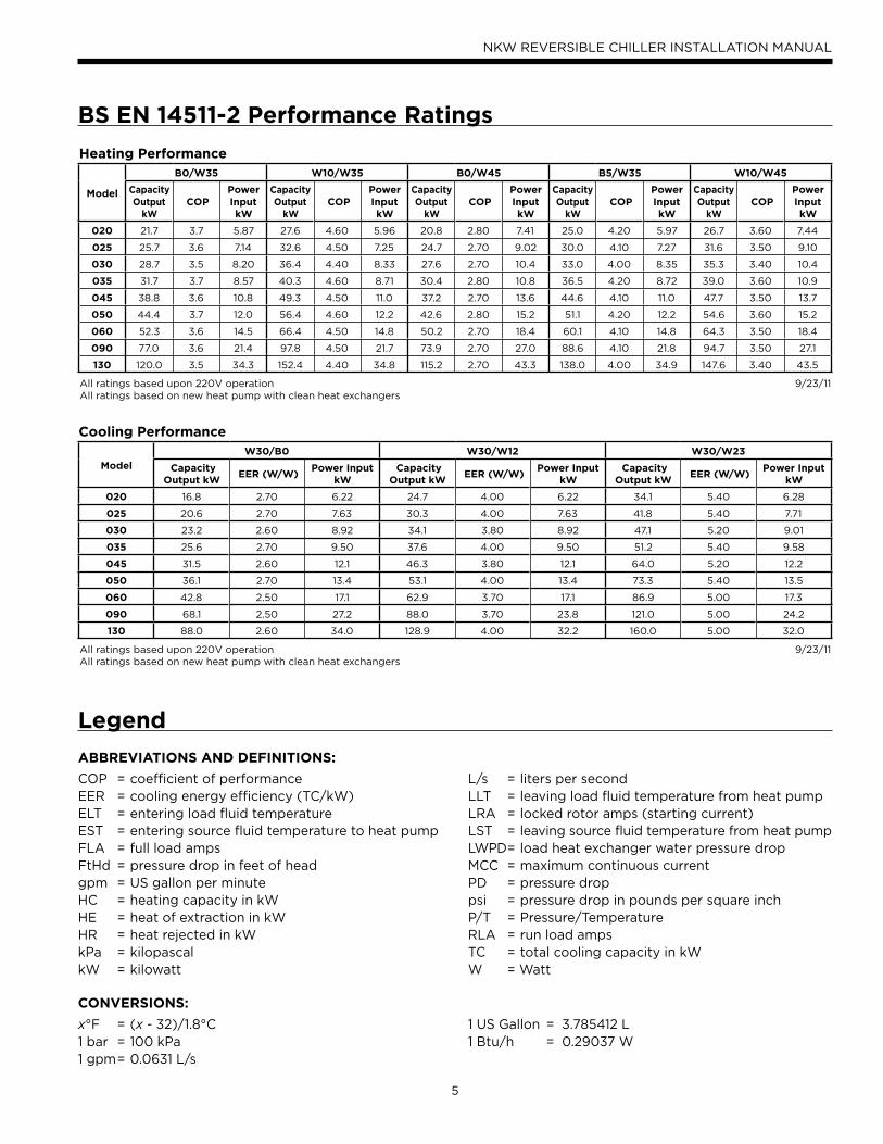
BS EN 14511-2 Performance Ratings
Legend
ABBREVIATIONS AND DEFINITIONS:
COP = coefficient of performanceEER = cooling energy efficiency (TC/kW)ELT = entering load fluid temperatureEST = entering source fluid temperature to heat pumpFLA = full load ampsFtHd = pressure drop in feet of headgpm = US gallon per minuteHC = heating capacity in kWHE = heat of extraction in kWHR = heat rejected in kWkPa = kilopascalkW = kilowatt
L/s = liters per secondLLT = leaving load fluid temperature from heat pumpLRA = locked rotor amps (starting current)LST = leaving source fluid temperature from heat pumpLWPD = load heat exchanger water pressure dropMCC = maximum continuous currentPD = pressure droppsi = pressure drop in pounds per square inchP/T = Pressure/TemperatureRLA = run load ampsTC = total cooling capacity in kWW = Watt
Heating Performance
Model
B0/W35 W10/W35 B0/W45 B5/W35 W10/W45
Capacity Output
kW COP
Power Input kW
Capacity Output
kW COP
Power Input kW
Capacity Output
kW COP
Power Input kW
Capacity Output
kW COP
Power Input kW
Capacity Output
kW COP
Power Input kW
020 21.7 3.7 5.87 27.6 4.60 5.96 20.8 2.80 7.41 25.0 4.20 5.97 26.7 3.60 7.44
025 25.7 3.6 7.14 32.6 4.50 7.25 24.7 2.70 9.02 30.0 4.10 7.27 31.6 3.50 9.10
030 28.7 3.5 8.20 36.4 4.40 8.33 27.6 2.70 10.4 33.0 4.00 8.35 35.3 3.40 10.4
035 31.7 3.7 8.57 40.3 4.60 8.71 30.4 2.80 10.8 36.5 4.20 8.72 39.0 3.60 10.9
045 38.8 3.6 10.8 49.3 4.50 11.0 37.2 2.70 13.6 44.6 4.10 11.0 47.7 3.50 13.7
050 44.4 3.7 12.0 56.4 4.60 12.2 42.6 2.80 15.2 51.1 4.20 12.2 54.6 3.60 15.2
060 52.3 3.6 14.5 66.4 4.50 14.8 50.2 2.70 18.4 60.1 4.10 14.8 64.3 3.50 18.4
090 77.0 3.6 21.4 97.8 4.50 21.7 73.9 2.70 27.0 88.6 4.10 21.8 94.7 3.50 27.1
130 120.0 3.5 34.3 152.4 4.40 34.8 115.2 2.70 43.3 138.0 4.00 34.9 147.6 3.40 43.5
All ratings based upon 220V operationAll ratings based on new heat pump with clean heat exchangers
9/23/11
Cooling Performance
Model
W30/B0 W30/W12 W30/W23
Capacity Output kW
EER (W/W) Power Input
kW Capacity
Output kW EER (W/W)
Power Input kW
Capacity Output kW
EER (W/W) Power Input
kW
020 16.8 2.70 6.22 24.7 4.00 6.22 34.1 5.40 6.28
025 20.6 2.70 7.63 30.3 4.00 7.63 41.8 5.40 7.71
030 23.2 2.60 8.92 34.1 3.80 8.92 47.1 5.20 9.01
035 25.6 2.70 9.50 37.6 4.00 9.50 51.2 5.40 9.58
045 31.5 2.60 12.1 46.3 3.80 12.1 64.0 5.20 12.2
050 36.1 2.70 13.4 53.1 4.00 13.4 73.3 5.40 13.5
060 42.8 2.50 17.1 62.9 3.70 17.1 86.9 5.00 17.3
090 68.1 2.50 27.2 88.0 3.70 23.8 121.0 5.00 24.2
130 88.0 2.60 34.0 128.9 4.00 32.2 160.0 5.00 32.0
All ratings based upon 220V operationAll ratings based on new heat pump with clean heat exchangers
9/23/11
CONVERSIONS:
x°F = (x - 32)/1.8°C 1 bar = 100 kPa1 gpm = 0.0631 L/s
1 US Gallon = 3.785412 L1 Btu/h = 0.29037 W
6
NKW REVERSIBLE CHILLER INSTALLATION MANUAL
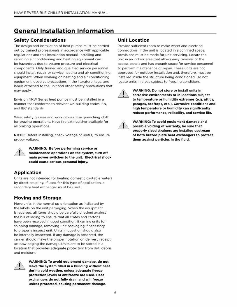
Safety ConsiderationsThe design and installation of heat pumps must be carried
out by trained professionals in accordance with applicable
regulations and this installation manual. Installing and
servicing air conditioning and heating equipment can
be hazardous due to system pressure and electrical
components. Only trained and qualified service personnel
should install, repair or service heating and air conditioning
equipment. When working on heating and air conditioning
equipment, observe precautions in the literature, tags, and
labels attached to the unit and other safety precautions that
may apply.
Envision NKW Series heat pumps must be installed in a
manner that conforms to relevant UK building codes, EN,
and IEC standards.
Wear safety glasses and work gloves. Use quenching cloth
for brazing operations. Have fire extinguisher available for
all brazing operations.
NOTE: Before installing, check voltage of unit(s) to ensure
proper voltage.
WARNING: Before performing service or maintenance operations on the system, turn off main power switches to the unit. Electrical shock could cause serious personal injury.
ApplicationUnits are not intended for heating domestic (potable water)
by direct coupling. If used for this type of application, a
secondary heat exchanger must be used.
Moving and StorageMove units in the normal up orientation as indicated by
the labels on the unit packaging. When the equipment
is received, all items should be carefully checked against
the bill of lading to ensure that all crates and cartons
have been received in good condition. Examine units for
shipping damage, removing unit packaging if necessary
to properly inspect unit. Units in question should also
be internally inspected. If any damage is observed, the
carrier should make the proper notation on delivery receipt
acknowledging the damage. Units are to be stored in a
location that provides adequate protection from dirt, debris
and moisture.
WARNING: To avoid equipment damage, do not leave the system filled in a building without heat during cold weather, unless adequate freeze protection levels of antifreeze are used. Heat exchangers do not fully drain and will freeze unless protected, causing permanent damage.
General Installation Information
Unit LocationProvide sufficient room to make water and electrical
connections. If the unit is located in a confined space,
provisions must be made for unit servicing. Locate the
unit in an indoor area that allows easy removal of the
access panels and has enough space for service personnel
to perform maintenance or repair. These units are not
approved for outdoor installation and, therefore, must be
installed inside the structure being conditioned. Do not
locate units in areas subject to freezing conditions.
WARNING: Do not store or install units in corrosive environments or in locations subject to temperature or humidity extremes (e.g. attics, garages, rooftops, etc.). Corrosive conditions and high temperature or humidity can significantly reduce performance, reliability, and service life. WARNING: To avoid equipment damage and possible voiding of warranty, be sure that properly sized strainers are installed upstream of both brazed plate heat exchangers to protect them against particles in the fluid.
7
NKW REVERSIBLE CHILLER INSTALLATION MANUAL
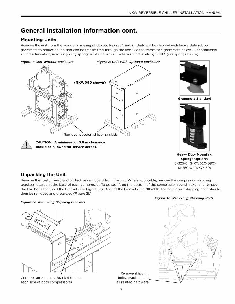
Mounting UnitsRemove the unit from the wooden shipping skids (see Figures 1 and 2). Units will be shipped with heavy duty rubber
grommets to reduce sound that can be transmitted through the floor via the frame (see grommets below). For additional
sound attenuation, use heavy duty spring isolation that can reduce sound levels by 3 dBA (see springs below).
Figure 1: Unit Without Enclosure Figure 2: Unit With Optional Enclosure
Unpacking the UnitRemove the stretch warp and protective cardboard from the unit. Where applicable, remove the compressor shipping
brackets located at the base of each compressor. To do so, lift up the bottom of the compressor sound jacket and remove
the two bolts that hold the bracket (see Figure 3a). Discard the brackets. On NKW130, the hold down shipping bolts should
then be removed and discarded (Figure 3b).
Figure 3a: Removing Shipping Brackets
Remove wooden shipping skids
CAUTION: A minimum of 0.6 m clearance should be allowed for service access.
General Installation Information cont.
Compressor Shipping Bracket (one on
each side of both compressors)
Figure 3b: Removing Shipping Bolts
Remove shipping
bolts, brackets and
all related hardware
(NKW090 shown)
Grommets Standard
Heavy Duty MountingSprings Optional
IS-325-01 (NKW020-090)
IS-750-01 (NKW130)
8
NKW REVERSIBLE CHILLER INSTALLATION MANUAL
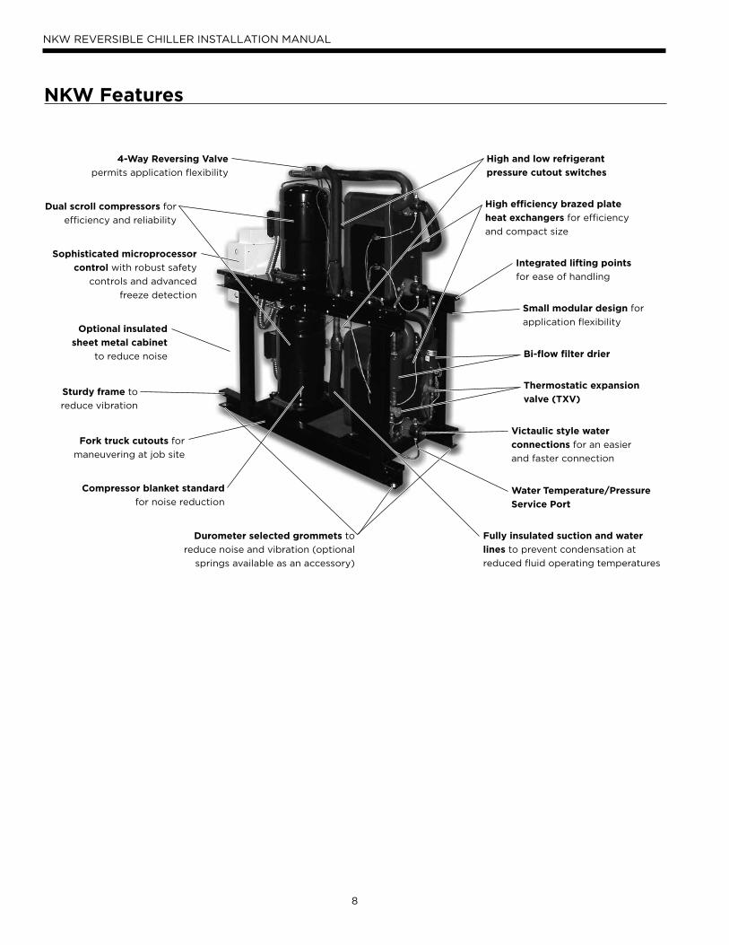
NKW Features
Dual scroll compressors for
efficiency and reliability
Optional insulated
sheet metal cabinet
to reduce noise
Sturdy frame to
reduce vibration
Fork truck cutouts for
maneuvering at job site
Compressor blanket standard
for noise reduction
Victaulic style water
connections for an easier
and faster connection
Small modular design for
application flexibility
Integrated lifting points
for ease of handling
High efficiency brazed plate
heat exchangers for efficiency
and compact size
4-Way Reversing Valve
permits application flexibility
Fully insulated suction and water
lines to prevent condensation at
reduced fluid operating temperatures
Sophisticated microprocessor
control with robust safety
controls and advanced
freeze detection
Durometer selected grommets to
reduce noise and vibration (optional
springs available as an accessory)
High and low refrigerant
pressure cutout switches
Bi-flow filter drier
Thermostatic expansion
valve (TXV)
Water Temperature/Pressure
Service Port
9
NKW REVERSIBLE CHILLER INSTALLATION MANUAL
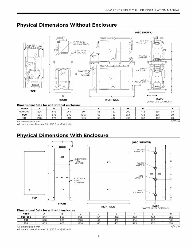
Physical Dimensions Without Enclosure
Dimensional Data for unit without enclosureModel A B C D E F G H J K
020-060 1295 572 965 891 155 432 202 432 285 38
090 1605 572 1270 1067 162 432 354 432 286 39
130 1778 572 1321 1215 166 432 495 432 362 20
All dimensions in mmAll water connections are 2 in. [50.8 mm] Victaulic
9/20/10
A
CB
E
F
G
H
J
D
FRONT RIGHT SIDE BACK
K
TOP
ELECTRICAL(LINE VOLTAGE)
ELECTRICAL(LOW VOLTAGE)
ELECTRICAL(LOW
VOLTAGE)
SOURCE WATER OUT
LOAD WATER IN
SOURCE WATER IN
LOAD WATER OUT
(WATER LINE LOCATIONS)
(090 SHOWN)
Physical Dimensions With Enclosure
Dimensional Data for unit with enclosureModel A B C D E F G H
020-060 1347 568 965 154 432 202 432 285
090 1620 608 1270 162 432 354 432 301
130 1803 607 1330 166 432 495 432 378
All dimensions in mmAll water connections are 2 in. [50.8 mm] Victaulic
9/20/10
RIGHT SIDE BACKC
A
B
D
E
F
G
HFRONT
TOP
LOAD WATER IN
SOURCE WATER IN
LOAD WATER OUT
SOURCE WATER OUT
ELECTRICAL(LOW VOLTAGE)
ELECTRICAL(LOW VOLTAGE)
(WATER LINE LOCATIONS)
(090 SHOWN)
10
NKW REVERSIBLE CHILLER INSTALLATION MANUAL
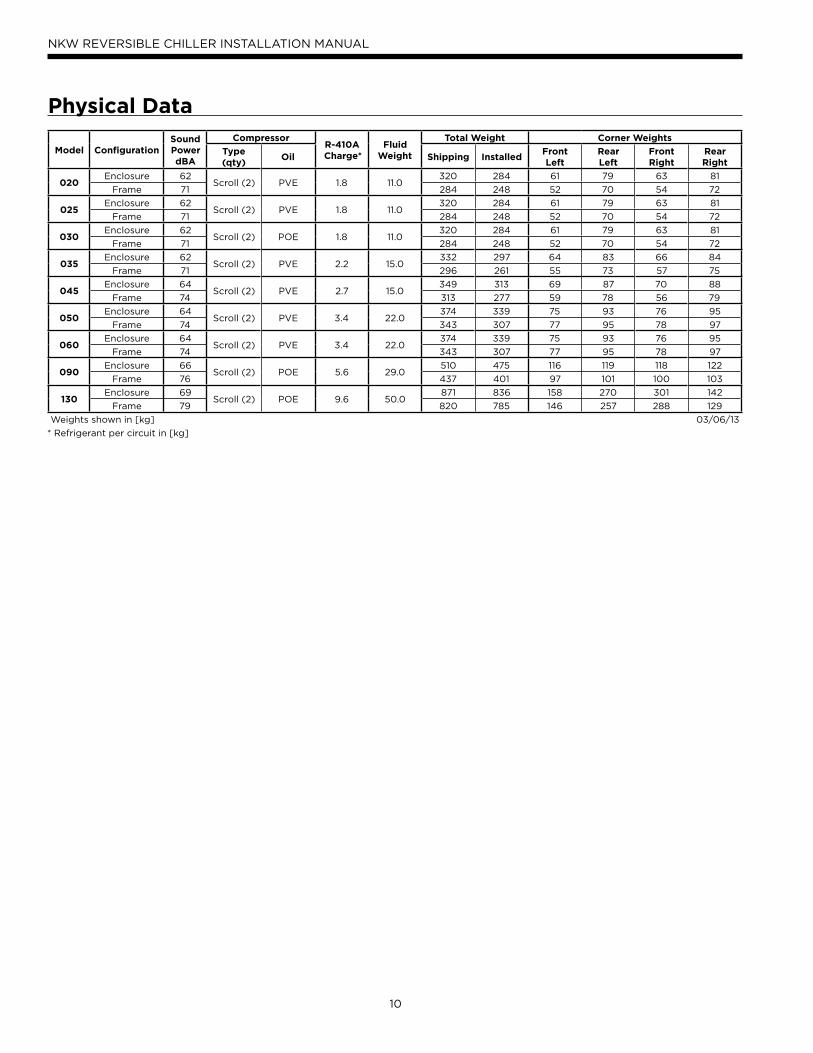
Physical Data
Model ConfigurationSound Power dBA
CompressorR-410A Charge*
Fluid Weight
Total Weight Corner Weights
Type(qty)
Oil Shipping InstalledFrontLeft
RearLeft
Front Right
Rear Right
020Enclosure 62
Scroll (2) PVE 1.8 11.0320 284 61 79 63 81
Frame 71 284 248 52 70 54 72
025Enclosure 62
Scroll (2) PVE 1.8 11.0320 284 61 79 63 81
Frame 71 284 248 52 70 54 72
030Enclosure 62
Scroll (2) POE 1.8 11.0320 284 61 79 63 81
Frame 71 284 248 52 70 54 72
035Enclosure 62
Scroll (2) PVE 2.2 15.0332 297 64 83 66 84
Frame 71 296 261 55 73 57 75
045Enclosure 64
Scroll (2) PVE 2.7 15.0349 313 69 87 70 88
Frame 74 313 277 59 78 56 79
050Enclosure 64
Scroll (2) PVE 3.4 22.0374 339 75 93 76 95
Frame 74 343 307 77 95 78 97
060Enclosure 64
Scroll (2) PVE 3.4 22.0374 339 75 93 76 95
Frame 74 343 307 77 95 78 97
090Enclosure 66
Scroll (2) POE 5.6 29.0510 475 116 119 118 122
Frame 76 437 401 97 101 100 103
130Enclosure 69
Scroll (2) POE 9.6 50.0871 836 158 270 301 142
Frame 79 820 785 146 257 288 129
Weights shown in [kg] 03/06/13
* Refrigerant per circuit in [kg]
11
NKW REVERSIBLE CHILLER INSTALLATION MANUAL
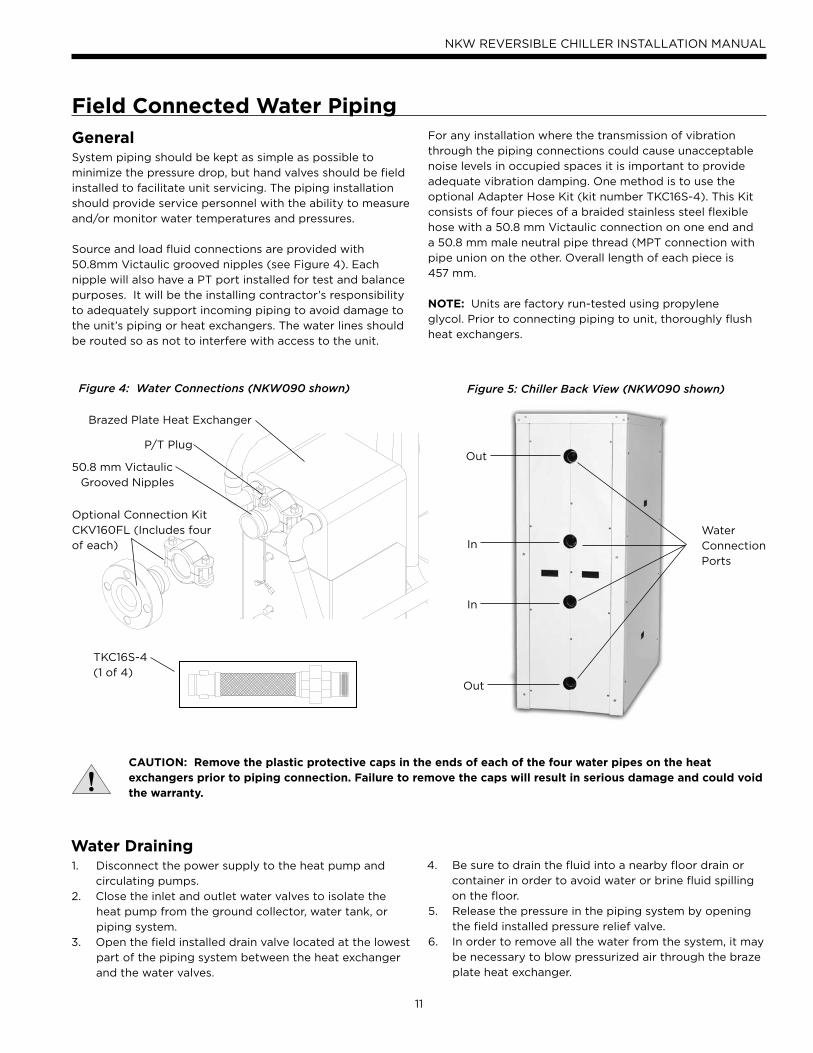
GeneralSystem piping should be kept as simple as possible to
minimize the pressure drop, but hand valves should be field
installed to facilitate unit servicing. The piping installation
should provide service personnel with the ability to measure
and/or monitor water temperatures and pressures.
Source and load fluid connections are provided with
50.8mm Victaulic grooved nipples (see Figure 4). Each
nipple will also have a PT port installed for test and balance
purposes. It will be the installing contractor’s responsibility
to adequately support incoming piping to avoid damage to
the unit’s piping or heat exchangers. The water lines should
be routed so as not to interfere with access to the unit.
Field Connected Water Piping
Figure 4: Water Connections (NKW090 shown)
P/T Plug
50.8 mm Victaulic
Grooved Nipples
Figure 5: Chiller Back View (NKW090 shown)
Water
Connection
Ports
Out
In
In
Out
Brazed Plate Heat Exchanger
Optional Connection Kit
CKV160FL (Includes four
of each)
TKC16S-4
(1 of 4)
CAUTION: Remove the plastic protective caps in the ends of each of the four water pipes on the heat exchangers prior to piping connection. Failure to remove the caps will result in serious damage and could void the warranty.
For any installation where the transmission of vibration
through the piping connections could cause unacceptable
noise levels in occupied spaces it is important to provide
adequate vibration damping. One method is to use the
optional Adapter Hose Kit (kit number TKC16S-4). This Kit
consists of four pieces of a braided stainless steel flexible
hose with a 50.8 mm Victaulic connection on one end and
a 50.8 mm male neutral pipe thread (MPT connection with
pipe union on the other. Overall length of each piece is
457 mm.
NOTE: Units are factory run-tested using propylene
glycol. Prior to connecting piping to unit, thoroughly flush
heat exchangers.
Water Draining1. Disconnect the power supply to the heat pump and
circulating pumps.
2. Close the inlet and outlet water valves to isolate the
heat pump from the ground collector, water tank, or
piping system.
3. Open the field installed drain valve located at the lowest
part of the piping system between the heat exchanger
and the water valves.
4. Be sure to drain the fluid into a nearby floor drain or
container in order to avoid water or brine fluid spilling
on the floor.
5. Release the pressure in the piping system by opening
the field installed pressure relief valve.
6. In order to remove all the water from the system, it may
be necessary to blow pressurized air through the braze
plate heat exchanger.
12
NKW REVERSIBLE CHILLER INSTALLATION MANUAL
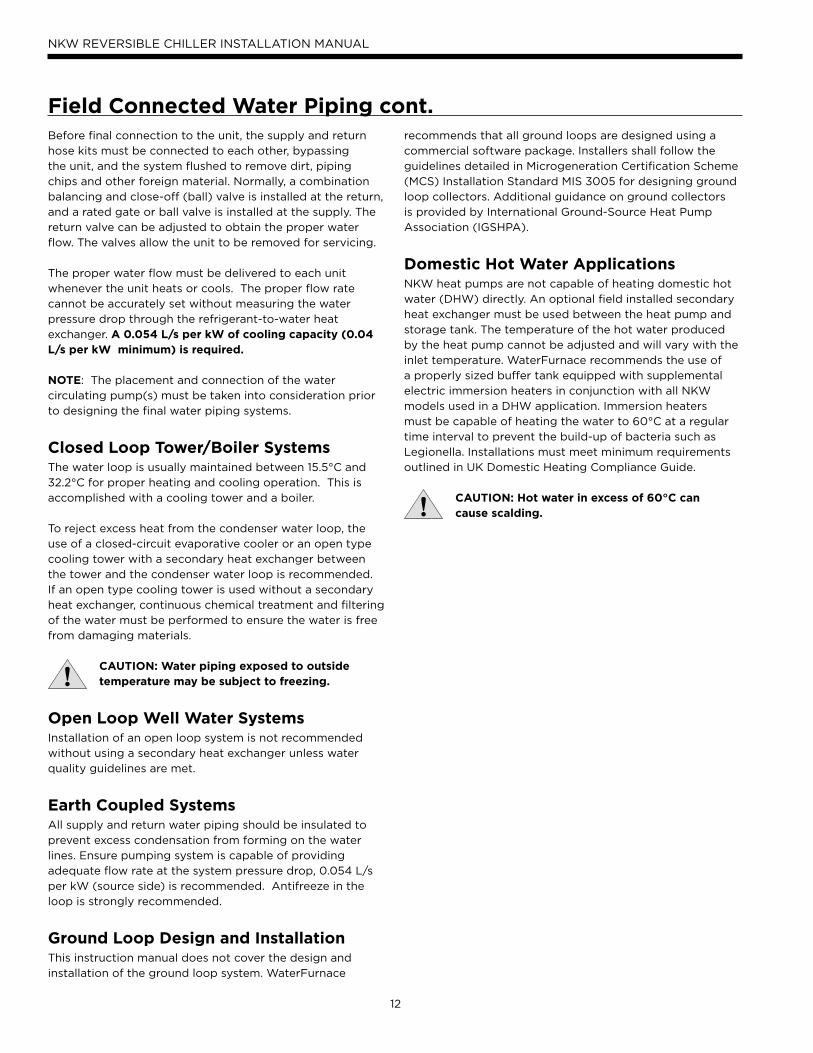
Field Connected Water Piping cont.Before final connection to the unit, the supply and return
hose kits must be connected to each other, bypassing
the unit, and the system flushed to remove dirt, piping
chips and other foreign material. Normally, a combination
balancing and close-off (ball) valve is installed at the return,
and a rated gate or ball valve is installed at the supply. The
return valve can be adjusted to obtain the proper water
flow. The valves allow the unit to be removed for servicing.
The proper water flow must be delivered to each unit
whenever the unit heats or cools. The proper flow rate
cannot be accurately set without measuring the water
pressure drop through the refrigerant-to-water heat
exchanger. A 0.054 L/s per kW of cooling capacity (0.04 L/s per kW minimum) is required.
NOTE: The placement and connection of the water
circulating pump(s) must be taken into consideration prior
to designing the final water piping systems.
Closed Loop Tower/Boiler SystemsThe water loop is usually maintained between 15.5°C and
32.2°C for proper heating and cooling operation. This is
accomplished with a cooling tower and a boiler.
To reject excess heat from the condenser water loop, the
use of a closed-circuit evaporative cooler or an open type
cooling tower with a secondary heat exchanger between
the tower and the condenser water loop is recommended.
If an open type cooling tower is used without a secondary
heat exchanger, continuous chemical treatment and filtering
of the water must be performed to ensure the water is free
from damaging materials.
CAUTION: Water piping exposed to outside temperature may be subject to freezing.
Open Loop Well Water SystemsInstallation of an open loop system is not recommended
without using a secondary heat exchanger unless water
quality guidelines are met.
Earth Coupled SystemsAll supply and return water piping should be insulated to
prevent excess condensation from forming on the water
lines. Ensure pumping system is capable of providing
adequate flow rate at the system pressure drop, 0.054 L/s
per kW (source side) is recommended. Antifreeze in the
loop is strongly recommended.
Ground Loop Design and InstallationThis instruction manual does not cover the design and
installation of the ground loop system. WaterFurnace
recommends that all ground loops are designed using a
commercial software package. Installers shall follow the
guidelines detailed in Microgeneration Certification Scheme
(MCS) Installation Standard MIS 3005 for designing ground
loop collectors. Additional guidance on ground collectors
is provided by International Ground-Source Heat Pump
Association (IGSHPA).
Domestic Hot Water ApplicationsNKW heat pumps are not capable of heating domestic hot
water (DHW) directly. An optional field installed secondary
heat exchanger must be used between the heat pump and
storage tank. The temperature of the hot water produced
by the heat pump cannot be adjusted and will vary with the
inlet temperature. WaterFurnace recommends the use of
a properly sized buffer tank equipped with supplemental
electric immersion heaters in conjunction with all NKW
models used in a DHW application. Immersion heaters
must be capable of heating the water to 60°C at a regular
time interval to prevent the build-up of bacteria such as
Legionella. Installations must meet minimum requirements
outlined in UK Domestic Heating Compliance Guide.
CAUTION: Hot water in excess of 60°C cancause scalding.
13
NKW REVERSIBLE CHILLER INSTALLATION MANUAL
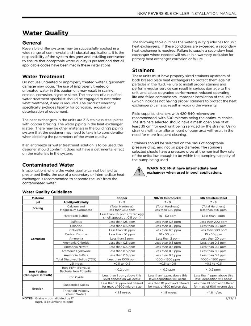
The following table outlines the water quality guidelines for unit heat exchangers. If these conditions are exceeded, a secondary heat exchanger is required. Failure to supply a secondary heat exchanger where needed will result in a warranty exclusion for primary heat exchanger corrosion or failure.
StrainersThese units must have properly sized strainers upstream of both brazed plate heat exchangers to protect them against particles in the fluid. Failure to install proper stainers and perform regular service can result in serious damage to the unit, and cause degraded performance, reduced operating life and failed compressors. Improper installation of the unit (which includes not having proper strainers to protect the heat exchangers) can also result in voiding the warranty.
Field supplied strainers with 420-840 microns are recommended, with 500 microns being the optimum choice. The strainers selected should have a mesh open area of at least 39 cm2 for each unit being serviced by the strainer. Using strainers with a smaller amount of open area will result in the need for more frequent cleaning.
Strainers should be selected on the basis of acceptable pressure drop, and not on pipe diameter. The strainers selected should have a pressure drop at the nominal flow rate of the units; low enough to be within the pumping capacity of the pump being used.
WARNING: Must have intermediate heat exchanger when used in pool applications.
GeneralReversible chiller systems may be successfully applied in a wide range of commercial and industrial applications. It is the responsibility of the system designer and installing contractor to ensure that acceptable water quality is present and that all applicable codes have been met in these installations.
Water TreatmentDo not use untreated or improperly treated water. Equipment damage may occur. The use of improperly treated or untreated water in this equipment may result in scaling, erosion, corrosion, algae or slime. The services of a qualified water treatment specialist should be engaged to determine what treatment, if any, is required. The product warranty specifically excludes liability for corrosion, erosion or deterioration of equipment.
The heat exchangers in the units are 316 stainless steel plates with copper brazing. The water piping in the heat exchanger is steel. There may be other materials in the building’s piping system that the designer may need to take into consideration when deciding the parameters of the water quality.
If an antifreeze or water treatment solution is to be used, the designer should confirm it does not have a detrimental effect on the materials in the system.
Contaminated WaterIn applications where the water quality cannot be held to prescribed limits, the use of a secondary or intermediate heat exchanger is recommended to separate the unit from the contaminated water.
Water Quality
Water Quality Guidelines
Material Copper 90/10 Cupronickel 316 Stainless Steel
pH Acidity/Alkalinity 7 - 9 7 - 9 7 - 9
ScalingCalcium and
Magnesium Carbonate(Total Hardness)
less than 350 ppm(Total Hardness)
less than 350 ppm(Total Hardness)
less than 350 ppm
Corrosion
Hydrogen SulfideLess than 0.5 ppm (rotten egg
smell appears at 0.5 ppm)10 - 50 ppm Less than 1 ppm
Sulfates Less than 125 ppm Less than 125 ppm Less than 200 ppm
Chlorine Less than 0.5 ppm Less than 0.5 ppm Less than 0.5 ppm
Chlorides Less than 20 ppm Less than 125 ppm Less than 300 ppm
Carbon Dioxide Less than 50 ppm 10 - 50 ppm 10 - 50 ppm
Ammonia Less than 2 ppm Less than 2 ppm Less than 20 ppm
Ammonia Chloride Less than 0.5 ppm Less than 0.5 ppm Less than 0.5 ppm
Ammonia Nitrate Less than 0.5 ppm Less than 0.5 ppm Less than 0.5 ppm
Ammonia Hydroxide Less than 0.5 ppm Less than 0.5 ppm Less than 0.5 ppm
Ammonia Sulfate Less than 0.5 ppm Less than 0.5 ppm Less than 0.5 ppm
Total Dissolved Solids (TDS) Less than 1000 ppm 1000 - 1500 ppm 1000 - 1500 ppm
LSI Index +0.5 to -0.5 +0.5 to -0.5 +0.5 to -0.5
Iron Fouling(Biological Growth)
Iron, FE2+ (Ferrous)Bacterial Iron Potential
< 0.2 ppm < 0.2 ppm < 0.2 ppm
Iron OxideLess than 1 ppm, above this level deposition will occur
Less than 1 ppm, above this level deposition will occur
Less than 1 ppm, above this level deposition will occur
ErosionSuspended Solids
Less than 10 ppm and filtered for max. of 600 micron size
Less than 10 ppm and filtered for max. of 600 micron size
Less than 10 ppm and filtered for max. of 600 micron size
Threshold Velocity(Fresh Water)
< 1.8 m/sec < 1.8 m/sec < 1.8 m/sec
NOTES: Grains = ppm divided by 17mg/L is equivalent to ppm
2/22/12
14
NKW REVERSIBLE CHILLER INSTALLATION MANUAL
System Cleaning and Flushing
Cleaning and FlushingPrior to start up of any heat pump, the water circulating
system must be cleaned and flushed of all dirt and debris.
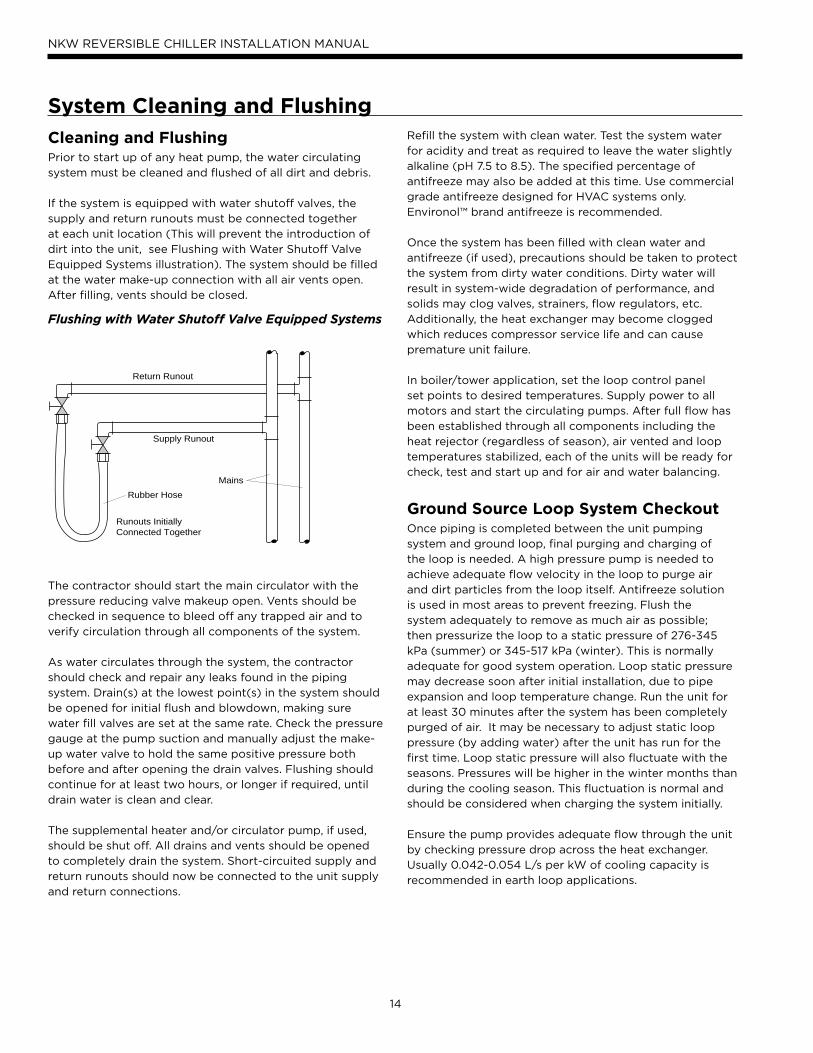
If the system is equipped with water shutoff valves, the
supply and return runouts must be connected together
at each unit location (This will prevent the introduction of
dirt into the unit, see Flushing with Water Shutoff Valve
Equipped Systems illustration). The system should be filled
at the water make-up connection with all air vents open.
After filling, vents should be closed.
The contractor should start the main circulator with the
pressure reducing valve makeup open. Vents should be
checked in sequence to bleed off any trapped air and to
verify circulation through all components of the system.
As water circulates through the system, the contractor
should check and repair any leaks found in the piping
system. Drain(s) at the lowest point(s) in the system should
be opened for initial flush and blowdown, making sure
water fill valves are set at the same rate. Check the pressure
gauge at the pump suction and manually adjust the make-
up water valve to hold the same positive pressure both
before and after opening the drain valves. Flushing should
continue for at least two hours, or longer if required, until
drain water is clean and clear.
The supplemental heater and/or circulator pump, if used,
should be shut off. All drains and vents should be opened
to completely drain the system. Short-circuited supply and
return runouts should now be connected to the unit supply
and return connections.
Refill the system with clean water. Test the system water
for acidity and treat as required to leave the water slightly
alkaline (pH 7.5 to 8.5). The specified percentage of
antifreeze may also be added at this time. Use commercial
grade antifreeze designed for HVAC systems only.
Environol™ brand antifreeze is recommended.
Once the system has been filled with clean water and
antifreeze (if used), precautions should be taken to protect
the system from dirty water conditions. Dirty water will
result in system-wide degradation of performance, and
solids may clog valves, strainers, flow regulators, etc.
Additionally, the heat exchanger may become clogged
which reduces compressor service life and can cause
premature unit failure.
In boiler/tower application, set the loop control panel
set points to desired temperatures. Supply power to all
motors and start the circulating pumps. After full flow has
been established through all components including the
heat rejector (regardless of season), air vented and loop
temperatures stabilized, each of the units will be ready for
check, test and start up and for air and water balancing.
Ground Source Loop System CheckoutOnce piping is completed between the unit pumping
system and ground loop, final purging and charging of
the loop is needed. A high pressure pump is needed to
achieve adequate flow velocity in the loop to purge air
and dirt particles from the loop itself. Antifreeze solution
is used in most areas to prevent freezing. Flush the
system adequately to remove as much air as possible;
then pressurize the loop to a static pressure of 276-345
kPa (summer) or 345-517 kPa (winter). This is normally
adequate for good system operation. Loop static pressure
may decrease soon after initial installation, due to pipe
expansion and loop temperature change. Run the unit for
at least 30 minutes after the system has been completely
purged of air. It may be necessary to adjust static loop
pressure (by adding water) after the unit has run for the
first time. Loop static pressure will also fluctuate with the
seasons. Pressures will be higher in the winter months than
during the cooling season. This fluctuation is normal and
should be considered when charging the system initially.
Ensure the pump provides adequate flow through the unit
by checking pressure drop across the heat exchanger.
Usually 0.042-0.054 L/s per kW of cooling capacity is
recommended in earth loop applications.
Return Runout
Supply Runout
Mains
Rubber Hose
Runouts InitiallyConnected Together
Flushing with Water Shutoff Valve Equipped Systems
15
NKW REVERSIBLE CHILLER INSTALLATION MANUAL
Electrical Data
ElectricalBe sure the available power is the same voltage and phase
as that shown on the unit serial plate. Line and low voltage
wiring must be done in accordance with local codes or the
17th Edition IEE Wiring Regulations, whichever is applicable.
Refer to the Electrical Data table for wire and fuse or circuit
breaker sizing information.
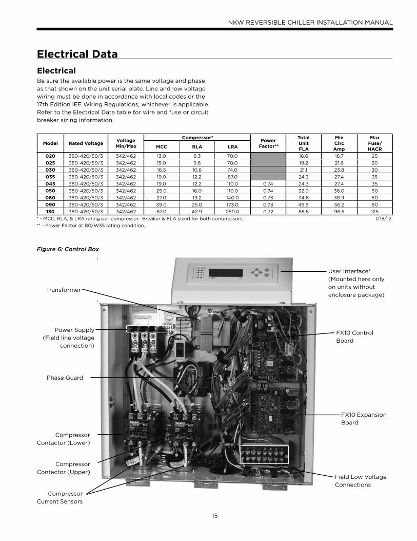
Figure 6: Control Box
Transformer
Power Supply
(Field line voltage
connection)
Phase Guard
Compressor
Contactor (Lower)
Compressor
Contactor (Upper)
Compressor
Current Sensors
Field Low Voltage
Connections
FX10 Control
Board
FX10 Expansion
Board
User Interface*
(Mounted here only
on units without
enclosure package)
Model Rated VoltageVoltageMin/Max
Compressor*Power
Factor**
TotalUnitFLA
MinCircAmp
MaxFuse/HACRMCC RLA LRA
020 380-420/50/3 342/462 13.0 8.3 70.0 16.6 18.7 25
025 380-420/50/3 342/462 15.0 9.6 70.0 19.2 21.6 30
030 380-420/50/3 342/462 16.5 10.6 74.0 21.1 23.8 30
035 380-420/50/3 342/462 19.0 12.2 87.0 24.3 27.4 35
045 380-420/50/3 342/462 19.0 12.2 110.0 0.74 24.3 27.4 35
050 380-420/50/3 342/462 25.0 16.0 110.0 0.74 32.0 36.0 50
060 380-420/50/3 342/462 27.0 19.2 140.0 0.73 34.6 38.9 60
090 380-420/50/3 342/462 39.0 25.0 173.0 0.73 49.9 56.2 80
130 380-420/50/3 342/462 67.0 42.9 250.0 0.72 85.8 96.5 125
* - MCC, RLA, & LRA rating per compressor. Breaker & FLA sized for both compressors. 1/18/12
** - Power Factor at B0/W35 rating condition.
16
NKW REVERSIBLE CHILLER INSTALLATION MANUAL
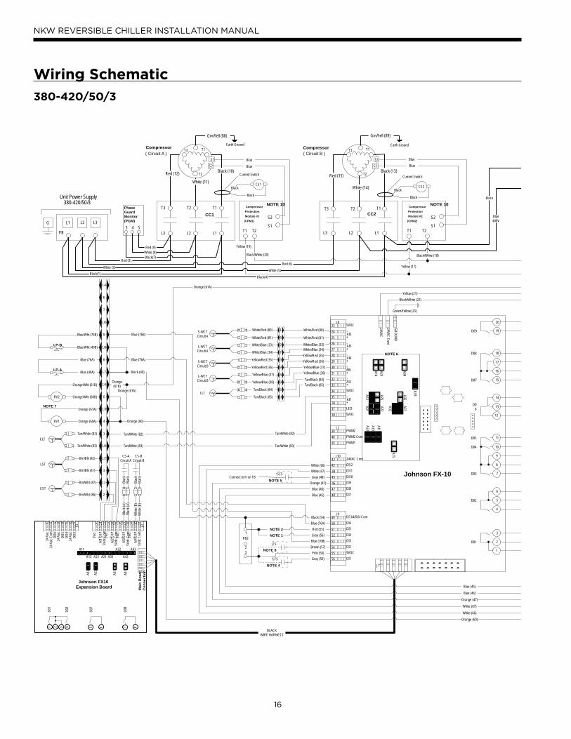
Wiring Schematic
380-420/50/3
SFS
LFS
ES
Johnson FX-10
5VDC
AI3
35
36
37
38
+
-
AI5-
+
AI4-
+
AI6
AI2
AI1
5VDC
5VDC
LED
-
-
-
+
+
+
24VAC
24VAC C
om
GR
OU
ND
39
40
41
PWM2
PWM2 Com
PWM1
42
43
44
45
46
47
48
24VAC Com
DI12
DI11
DI10
DI9
DI8
DI7
49
50
51
52
53
54
55
56
DI 3/4/5/6/ Com
DI6
DI5
DI4
DI3
DI2
DI1
9VDC
20
19
18
17
16
15
14
13
12
11
10
9
8
7
6
5
4
3
2
1
D09
D08
D07
D06
D05
D04
D03
D02
D01
J8
J2
J10
J9
J7
NOTE 6
A21A12
A25A22
A32
A31A35
A23
A13
A11
A15
A14
A24
A34
A3334
LP-A
LP-B
313029282726252423222120
AI4
EXP
5Vdc
Com
J2
5Vd
c
5Vdc
Com
AI3
EXP
5Vd
c
5Vdc
Com
AI2
EXP
5Vd
c
5Vdc
Com
AI1
EXP
5Vd
c
1716151413121110
DO
324
Vac
DO
4D
O5
DO
6
24 V
ac24
Vac
Com
J3
24 V
ac
J1M
ain
Boa
rd
Con
nect
ion
A41
A31
A23
A13
A43
A42
A32
A33A21A22A12
A11
4321
D02
D01
6
D07
5 8
D08
7
Johnson FX10Expansion Board
Unit Power Supply380-420/50/3
G
( Circuit A )Compressor
CC1
L1L2L3
T1T2T3
Black (10)Red (12)
White (11)
T1 T2
S2
S1
CompressorProtectionModule #1
(CPM1)
Blue
Blue
T1
T2
T3
S1
S2
Current Switch
CS1
Black
Black
Earth Ground
Grn/Yell (88)
CC2
L1L2L3
T1T2T3
Black (13)Red (15)
T1 T2
S2
S1
CompressorProtectionModule #2
(CPM2)
Blue
Blue
( Circuit B )T1
T2
T3
S1
S2
White (14)
Current Switch
CS2
Black
Black
Compressor Earth Ground
Grn/Yell (89)
PB
L1 L2 L3
33
32
31
30
29
28
27
26
25
24
231
6
2
7
3
4
9
5
10
8
White/Red (80)
White/Red (81)
White/Blue (33)White/Blue (34)
Yellow/Red (35)
Yellow/Red (36)
Yellow/Blue (37)
Yellow/Blue (38)
Tan/Black (84)
Tan/Black (85)
White/Red (80)
White/Red (81)T
T
T
T
White/Blue (33)
White/Blue (34)
Yellow/Red (35)
Yellow/Red (36)
TYellow/Blue (37)
Yellow/Blue (38)
Tan/Black (84)
Tan/Black (85)
S-WCTCircuit A
L-WCTCircuit A
S-WCTCircuit B
L-WCTCircuit B
LLT
Green/Yellow (23)
Yellow (21)
Black/White (22)
23
1
PB2
Black (54)
Red (55)
Gray (56)
Pink (58)
Brown (57)
Gray (59)
14
6
7
16
9
8
17
14
5
18
13
4
1
3
12
10
11
2TEST
Brn/Wht (86)
Brn/Wht (87)
TLST
Brn/Blk (41)
Brn/Blk (42)
Blac
kBl
ack
CS-ACircuit A
Blac
kBl
ack
CS-BCircuit B
Blue (45)
Blue (46)
Blue (45)
Blue (46)
Orange (47)
Orange (47)
Gray (48)Connect to R on TB
White (67)
White (67)
White (66)
White (66)
Orange (60)
Orange (60)
Tan/White (82)
Tan/White (83)
Blac
k (A
)Bl
ack
(A)
Whi
te (B
)W
hite
(B)
Orange (61A)
Orange (61A)
RV1
RV2
Orange (60A)
Orange (61A)
Orange/Wht (60B)
Orange/Wht (61B)
TELT
Tan/White (82)
Tan/White (83)
Tan/White (82)
Tan/White (83)
Black (49)
Blue (76A)
Blue (76A)
Blue (76B)
Blue (76B)
Blue (49A)
Blue (76A)
Blue/Wht (49B)
Blue/Wht (76B)
BLACKWIRE HARNESS
Black(1)
White (2)
Red (3)
Black(4)
White (5)
Red (6)
Black(7)White (8)Red (9)
Yellow (17)
Black/White (18)
Yellow (19)
Black/White (20)
NOTE 1NOTE 2
NOTE 4
NOTE 5
NOTE 7
NOTE 8
NOTE 10NOTE 10
543
PhaseGuardMonitor(PGM)
Orange (61B)
Blue400V
Black
17
NKW REVERSIBLE CHILLER INSTALLATION MANUAL
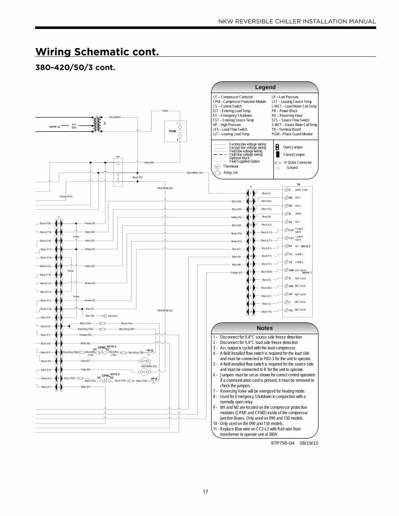
Wiring Schematic cont.
97P795-04 08/19/10
HP-B
HP-A
PB1
23
1
Black (F1)
Black (F2)
Black (F3)
Black (F4)
Black (F5)
Black (F6)
Black (F7)
Black (F8)
Black (F9)
Black (F10)
Black (F11)
Black (F12)
Black (F13)
Black (F14)
Black (F15)
Black (F16)
Black (F17)
Black (F18)
Black (F19)
Black (F20)
1
2
3
4
5
7
8
9
10
6
11
12
13
16
15
14
17
20
19
18
A
Yellow
Yellow
Yellow
Yellow (24)
Black (95)
Y1 COMP 1
LC1 Comp AAlarm
RS DO-9
X2 DO-7
R 24VAC
SS DO-8
LC2 Comp BAlarm
X1 Acc
C 24VAC COM
TO NOT USED
SC NOT USED
AIC NOT USED
L NOT USED
O/B REV VALVE
G NOT USED
Y2 COMP 2
16
12
8
2
9
4
10
7
5
3
11
14
6
13
15
1
TB
Black (SS)
Black (C)
Black (RS)
Black (R)
Black (X2)
Black (LC2)
Black (LC1)
Black (X1)
Black (Y1)
Black (Y2)
Black (O/B)
Black (G)
Black (AIC)
Black (SC)
Black (L)
Black (TO)
B
Black/White (26)
Black (30)
Black (30)
Black (29)
Black (29)
Yellow (25)
Yellow (25)
Black (28)
Black (28)
Brown (53)
Brown (53)
Brown (52)
Brown (52)
Blue (51)
Blue (51)
Black (75A)
Black/Org (75B)
Black/Org (73B)
Black/Org (74B)
CC-B
CC-A
Black (73A)
Black (74A)
Violet (67)
Violet (66)Black/White (63)
Black/White (62)
Black/White (62)
Blue (45)
Blue (46)
Orange (47)
White (67)
White (66)
Blue (50) Not Used
Orange (60)
Orange (61A)
CPM1M2M1Black (70A)
CPM2M2M1
Black/Org (70B)
Yellow (80)
Black (72A)
Black/Org (72B)
Notes1 - Disconnect for 9.4°C source side freeze detection2 - Disconnect for 9.4°C load side freeze detection3 - Acc output is cycled with the lead compressor.4 - A field installed flow switch is required for the load side and must be connected to PB2-3 for the unit to operate.5 - A field installed flow switch is required for the source side and must be connected to R for the unit to operate.6 - Jumpers must be set as shown for correct control operation. If a communication card is present, it must be removed to check the jumpers.7 - Reversing Valve will be energized for heating mode.8 - Used for Emergency Shutdown in conjunction with a normally open relay9 - M1 and M2 are located on the compressor protection modules (CPM1 and CPM2) inside of the compressor junction Boxes. Only used on 090 and 130 models.10 - Only used on the 090 and 130 models.11 - Replace Blue wire on CC2-L2 with Red wire from transformer to operate unit at 380V.
NOTE 3
NOTE 7
NOTE 9
NOTE 9
Ground
LegendCC – Compressor ContactorCPM – Compressor Protection ModuleCS – Current SwitchELT – Entering Load TempES – Emergency ShutdownEST – Entering Source TempHP – High PressureLFS – Load Flow SwitchLLT – Leaving Load Temp
LP – Low PressureLST – Leaving Source TempL-WCT – Load Water Coil TempPB – Power BlockRV – Reversing ValveSFS – Source Flow SwitchS-WCT – Source Water Coil TempTB – Terminal BoardPGM – Phase Guard Monitor
Factory low voltage wiringFactory line voltage wiringField low voltage wiringField line voltage wiringOptional blockField Supplied Option
Thermistor
Relay coilT
Open Jumper
Closed Jumper
¼” Quick Connector
PGM
8
1
Black/Org (71B)
Black (71A)
24V
Tran
sfor
mer
NOTE 11
Black/White
Yellow
Red380V
380-420/50/3 cont.
18
NKW REVERSIBLE CHILLER INSTALLATION MANUAL
TB Typical T-Stat
24VAC
24V COM
Comp 1
Comp 2
Rev Valve
Acc 2
Acc 1
Alarm
Circuit 1 Alarm
Circuit 2 Alarm
24VAC
24V COM
Comp 1
Comp 2
Rev Valve
Accessory Item 1
R
C
Y1
Y2
O/B
X2
X1
L
LC1
LC2
R
C
Y1
Y2
B
NOTES: 1) Acc Output 1 is cycled with the lead compressor 2) Acc Output 2 is cycled with the lag compressor
Unit Power Supply380-420/50/3
G L3 L1L2PB
Black
Red
White
Black
White
Red
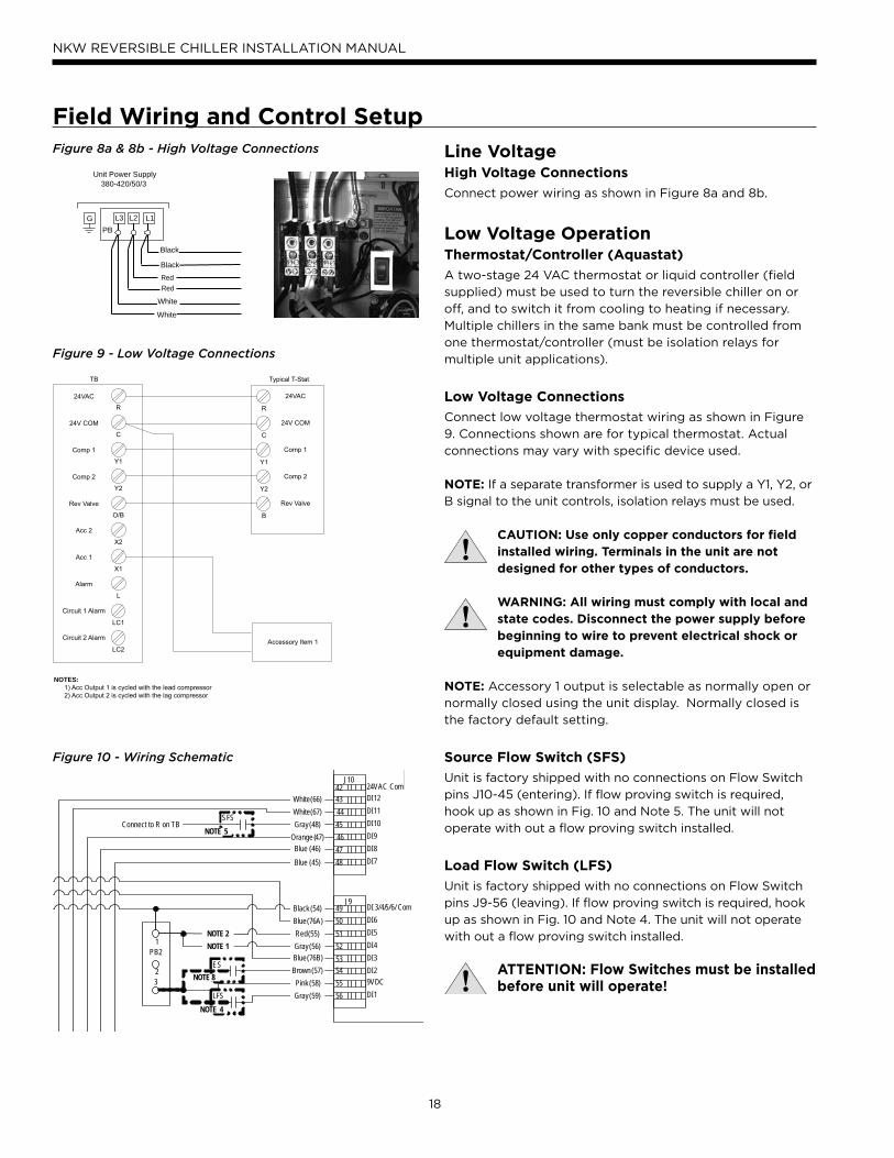
Field Wiring and Control SetupFigure 8a & 8b - High Voltage Connections
Figure 9 - Low Voltage Connections
Line VoltageHigh Voltage Connections
Connect power wiring as shown in Figure 8a and 8b.
Low Voltage OperationThermostat/Controller (Aquastat)
A two-stage 24 VAC thermostat or liquid controller (field
supplied) must be used to turn the reversible chiller on or
off, and to switch it from cooling to heating if necessary.
Multiple chillers in the same bank must be controlled from
one thermostat/controller (must be isolation relays for
multiple unit applications).
Low Voltage Connections
Connect low voltage thermostat wiring as shown in Figure
9. Connections shown are for typical thermostat. Actual
connections may vary with specific device used.
NOTE: If a separate transformer is used to supply a Y1, Y2, or
B signal to the unit controls, isolation relays must be used.
CAUTION: Use only copper conductors for field installed wiring. Terminals in the unit are not designed for other types of conductors.
WARNING: All wiring must comply with local and state codes. Disconnect the power supply before beginning to wire to prevent electrical shock or equipment damage.
NOTE: Accessory 1 output is selectable as normally open or
normally closed using the unit display. Normally closed is
the factory default setting.
Source Flow Switch (SFS)
Unit is factory shipped with no connections on Flow Switch
pins J10-45 (entering). If flow proving switch is required,
hook up as shown in Fig. 10 and Note 5. The unit will not
operate with out a flow proving switch installed.
Load Flow Switch (LFS)
Unit is factory shipped with no connections on Flow Switch
pins J9-56 (leaving). If flow proving switch is required, hook
up as shown in Fig. 10 and Note 4. The unit will not operate
with out a flow proving switch installed.
ATTENTION: Flow Switches must be installed before unit will operate!
Figure 10 - Wiring Schematic
SFS
LFS
ES
42
43
44
45
46
47
48
24VAC Com
DI12
DI11
DI10
DI9
DI8
DI7
49
50
51
52
53
54
55
56
DI 3/4/5/6/ Com
DI6
DI5
DI4
DI3
DI2
DI1
9VDC
J10
J9
23
1PB2
Black (54)
Red (55)
Gray (56)
Pink (58)
Brown (57)
Gray (59)
Blue (45)
Blue (46)
Orange (47)
Gray (48)Connect to R on TB
White (67)
White (66)
Blue (76A)
Blue (76B)
NOTE 1
NOTE 2
NOTE 4
NOTE 5
NOTE 8
19
NKW REVERSIBLE CHILLER INSTALLATION MANUAL
Field Wiring and Control Setup cont.Accessory Relay Setup
The accessory output set to “close” upon Y1 compressor call (compressor is delayed 90 sec. after Y1) but can be set to
“open” with Y1.
To change ACC1 or ACC2: (ACC1 shown)
• On FX10 control using the left and right arrow keys, scroll to “PASSWORD” menu (password “5667”)
• Once you have entered the password scroll to “MAINT” menu.
• Using up and down keys, scroll to “Acc 1 Sel” hit “ENTER” and “ON Comp” begins flashing
• Using up and down keys, select “ON Comp” for actuation with Y1 Call or “OFF Comp” for deactivation with Y1
Lead/Lag Selection
Compressor Lead/Lag Selection is factory set to “ON” but can be set to “OFF”.
To change Lead/Lag On/Off:
• On FX10 control using the left and right arrow keys, scroll to “MAINT” menu
• Using up and down keys, scroll to “LEAD/LAG SELECT” hit “ENTER” and “OFF” begins flashing
• Using up and down keys, select “ON” for activation or “ OFF” for deactivation
°F or °C - Unit of Measure
Degrees Fahrenheit is factory set, however degrees Celsius can be selected using the following procedure:
To Change Unit of Measure:
• On FX10 control using up and down keys, scroll to “SETTINGS”
• Using up and down keys, scroll to “UNIT OF MEASURE” hit “ENTER” and “UNIT OF MEASURE” begins flashing
• Using up and down keys, select “F” for degrees Fahrenheit or “C” for degrees Celsius
Other Field Options
Other field selectable options are available as shown in the maintenance menu on page 20 of the FX10 control using a
similar procedure as shown in the above examples. These would include thermostat enabling, and emergency shutdown.
See page 20 for details.
DDC Operation & Connection
Consult your factory representative for application details.
20
NKW REVERSIBLE CHILLER INSTALLATION MANUAL
Verify the following:• High voltage is correct and matches nameplate
• Fuses, breakers and wire size are correct
• Low voltage wiring is complete
• Piping is complete and the water system has been
cleaned and flushed
• Air is purged from closed loop system
• Isolation valves are open and water control valves or loop
pumps are wired
• Service/access panels are in place
• Unit controls are in “off” position
• Flow switches are installed and ready or wires
are jumpered
• Freeze detection setpoints have been set in
the microprocessor
WARNING: Verify ALL water controls are open and allow water flow PRIOR to engaging the compressor. Failure to do so can result in freezing the heat exchanger or water lines causing permanent damage to the unit.
Startup Steps• Set thermostat control above cooling setpoint.
• Set thermostat control in cooling mode.
Unit Startup
• Slowly reduce the control setting until both the
compressor and water control valve/loop pumps are
activated. Verify that the compressor is on and that
the water flow rate is correct by measuring pressure
drop through the heat exchanger and comparing to the
Pressure Drop table. Check for correct rotation of scroll
compressors. Switch any two power leads at the L1, L2,
and L3 line voltage termination block if incorrect.
• Perform a cooling capacity test by multiplying L/s x ΔT
x 4.1 (antifreeze/water). Use 4.2 for 100% water. Check
capacity against catalog data at same conditions.
• Set control to “OFF” position.
• Leave unit “OFF” for approximately five (5) minutes to
allow pressure to equalize.
• Adjust control below heating setpoint.
• Set control in “HEAT” position mode.
• Slowly increase the control setting until both compressor
and water control valve/loop pumps are activated. The
reversing valve should be heard changing over.
• Perform a heating capacity test by multiplying L/s x ΔT
x 4.1 (antifreeze/water). Use 4.2 for 100% water. Check
capacity against catalog data at same conditions.
• Check for vibrations, noise and water leaks.
• Set system to maintain desired setpoint.
• Instruct the owner/operator of correct control and
system operation.
21
NKW REVERSIBLE CHILLER INSTALLATION MANUAL
FX10 Advanced Control Overview
• The Johnson Controls FX10 board is specifically designed
for commercial heat pumps and provides control of the
entire unit as well as input ports for Open N2, LonTalk,
BACnet (MS/TP @ 19,200 Baud Rate) communication
protocols as well as an input port for a user interface.
The user interface can be used to aid in diagnostics and
unit setup and is standard on all NKW chillers. A 16-
pin low voltage terminal board provides terminals for
common field connections. The FX10 Control provides:
• Operational sequencing
• High and low-pressure switch monitoring
• General lockout
• Advanced Freeze Detection Temperature Sensing
• Lockout mode control
• Emergency shutdown mode
• Random start and short cycle protection
Short Cycle Protection
Allows a minimum compressor “off” time of five minutes
and a minimum “on” time of two minutes.
Random Start
A delay of 1 to 120 seconds is generated after each power-
up to prevent simultaneous startup of all units within a
building after the release from an unoccupied cycle or
power loss.
Emergency Shutdown
A field-applied dry contact can be used to place the
control into emergency shutdown mode. During this mode,
all outputs on the board are disabled.
Freeze Detection Temperature Limit
Field selectable for -9.4° or 0.6°C
Installation Options
• Standalone controlled by aquastat
• Integrated into BAS by adding communication module
Accessory Outputs
Quantity 1. Cycled with the lead compressor. Field selectable
for normally open (factory default) or normally closed
through the building automation system or user interface.
User Interface
10 cm x 51 cm backlit LCD
Optional Plug-in Communication Modules -(compatible with standard BAS protocols)
• Open N2
• LonTalk
• BACnet (MS/TP @ 19,200 Baud Rate)
Display
One local display is standard on all NKW units. Up to
2 displays, either 1 local and 1 remote, or 2 remote. (A
2-display configuration requires identical displays.) Local
display can be up to 3 meters from the controller, power
supply, and data communication. Remote display can be
up to 300 meters from the controller. Remote display must
be independently powered with data communication done
via 3 pole shielded cable.
Control Timing & Fault Recognition Delays
Lead compressor “ON” delay ..........................................90 seconds
(not applicable for single compressor models)
Minimum compressor “ON” time ...................................... 2 minutes
(except for fault condition)
Short cycle delay ..................................................................... 5 minutes
Random start delay .......................................................0-120 seconds
High pressure fault .................................................................<1 second
Low pressure fault ...............................................................30 seconds
Freeze detection fault ...................................................0-30 seconds
Low pressure fault bypass ................................................... 2 minutes
Envision Controls - FX10
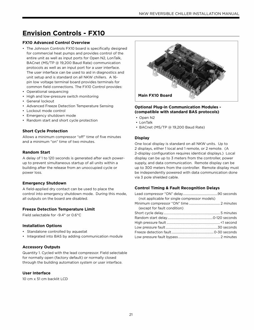
Main FX10 Board
22
NKW REVERSIBLE CHILLER INSTALLATION MANUAL
Envision Controls - FX10 cont.
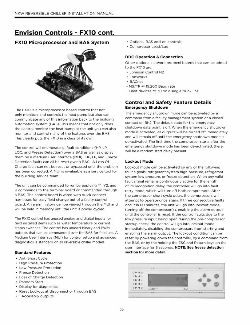
FX10 Microprocessor and BAS System
The FX10 is a microprocessor based control that not
only monitors and controls the heat pump but also can
communicate any of this information back to the building
automation system (BAS). This means that not only does
the control monitor the heat pump at the unit you can also
monitor and control many of the features over the BAS.
This clearly puts the FX10 in a class of its own.
The control will enumerate all fault conditions (HP, LP,
LOC, and Freeze Detection) over a BAS as well as display
them on a medium user interface (MUI). HP, LP, and Freeze
Detection faults can all be reset over a BAS. A Loss Of
Charge fault can not be reset or bypassed until the problem
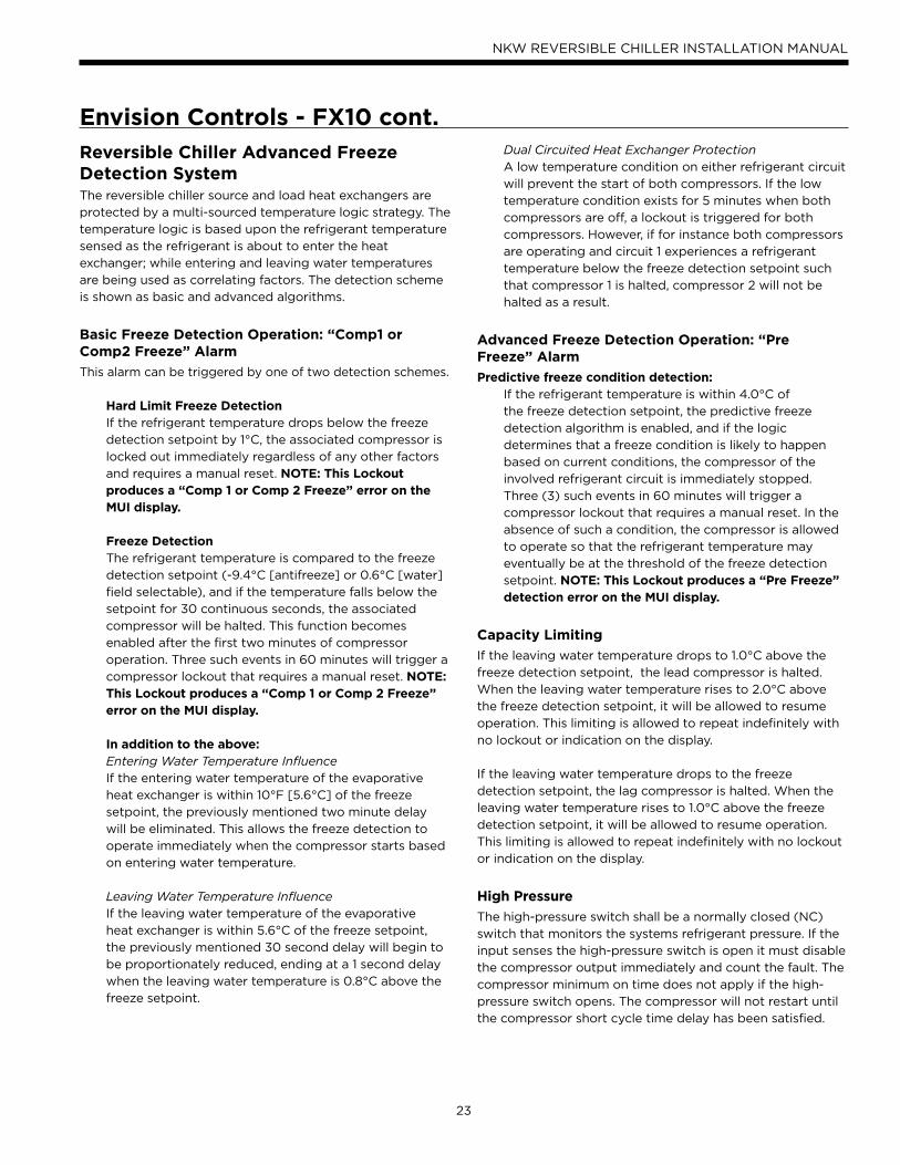
has been corrected. A MUI is invaluable as a service tool for
the building service team.
The unit can be commanded to run by applying Y1, Y2, and
B commands to the terminal board or commanded through
a BAS. The control board is wired with quick connect
harnesses for easy field change out of a faulty control
board. An alarm history can be viewed through the MUI and
will be held in memory until the unit is power cycled.
The FX10 control has unused analog and digital inputs for
field installed items such as water temperature or current
status switches. The control has unused binary and PWM
outputs that can be commanded over the BAS for field use. A
Medium User Interface (MUI) for control setup and advanced
diagnostics is standard on all reversible chiller models.
Standard Features
• Anti Short Cycle
• High Pressure Protection
• Low Pressure Protection
• Freeze Detection
• Loss of Charge Detection
• Random Start
• Display for diagnostics
• Reset Lockout at disconnect or through BAS
• 1 Accessory outputs
• Optional BAS add-on controls
• Compressor Lead/Lag
DDC Operation & Connection
Other optional network protocol boards that can be added
to the FX10 are:
• Johnson Control N2
• LonWorks
• BACnet
- MS/TP @ 19,200 Baud rate
- Limit devices to 30 on a single trunk line.
Control and Safety Feature DetailsEmergency Shutdown
The emergency shutdown mode can be activated by a
command from a facility management system or a closed
contact on BI-2. The default state for the emergency
shutdown data point is off. When the emergency shutdown
mode is activated, all outputs will be turned off immediately
and will remain off until the emergency shutdown mode is
de-activated. The first time the compressor starts after the
emergency shutdown mode has been de-activated, there
will be a random start delay present.
Lockout Mode
Lockout mode can be activated by any of the following
fault signals: refrigerant system high pressure, refrigerant
system low pressure, or freeze detection. When any valid
fault signal remains continuously active for the length
of its recognition delay, the controller will go into fault
retry mode, which will turn off both compressors. After
the compressor short cycle delay, the compressors will
attempt to operate once again. If three consecutive faults
occur in 60 minutes, the unit will go into lockout mode,
turning off the compressor(s), enabling the alarm output
until the controller is reset. If the control faults due to the
low pressure input being open during the pre-compressor
startup check, the control will go into lockout mode
immediately, disabling the compressors from starting and
enabling the alarm output. The lockout condition can be
reset by powering down the controller, by a command from
the BAS, or by the holding the ESC and Return keys on the
user interface for 5 seconds. NOTE: See freeze detection section for more detail.
23
NKW REVERSIBLE CHILLER INSTALLATION MANUAL
Envision Controls - FX10 cont.
Reversible Chiller Advanced Freeze Detection SystemThe reversible chiller source and load heat exchangers are
protected by a multi-sourced temperature logic strategy. The
temperature logic is based upon the refrigerant temperature
sensed as the refrigerant is about to enter the heat
exchanger; while entering and leaving water temperatures
are being used as correlating factors. The detection scheme
is shown as basic and advanced algorithms.
Basic Freeze Detection Operation: “Comp1 or Comp2 Freeze” Alarm
This alarm can be triggered by one of two detection schemes.
Hard Limit Freeze DetectionIf the refrigerant temperature drops below the freeze
detection setpoint by 1°C, the associated compressor is
locked out immediately regardless of any other factors
and requires a manual reset. NOTE: This Lockout produces a “Comp 1 or Comp 2 Freeze” error on the MUI display.
Freeze DetectionThe refrigerant temperature is compared to the freeze
detection setpoint (-9.4°C [antifreeze] or 0.6°C [water]
field selectable), and if the temperature falls below the
setpoint for 30 continuous seconds, the associated
compressor will be halted. This function becomes
enabled after the first two minutes of compressor
operation. Three such events in 60 minutes will trigger a
compressor lockout that requires a manual reset. NOTE: This Lockout produces a “Comp 1 or Comp 2 Freeze” error on the MUI display.
In addition to the above: Entering Water Temperature InfluenceIf the entering water temperature of the evaporative
heat exchanger is within 10°F [5.6°C] of the freeze
setpoint, the previously mentioned two minute delay
will be eliminated. This allows the freeze detection to
operate immediately when the compressor starts based
on entering water temperature.
Leaving Water Temperature InfluenceIf the leaving water temperature of the evaporative
heat exchanger is within 5.6°C of the freeze setpoint,
the previously mentioned 30 second delay will begin to
be proportionately reduced, ending at a 1 second delay
when the leaving water temperature is 0.8°C above the
freeze setpoint.
Dual Circuited Heat Exchanger ProtectionA low temperature condition on either refrigerant circuit
will prevent the start of both compressors. If the low
temperature condition exists for 5 minutes when both
compressors are off, a lockout is triggered for both
compressors. However, if for instance both compressors
are operating and circuit 1 experiences a refrigerant
temperature below the freeze detection setpoint such
that compressor 1 is halted, compressor 2 will not be
halted as a result.
Advanced Freeze Detection Operation: “Pre Freeze” Alarm
Predictive freeze condition detection:If the refrigerant temperature is within 4.0°C of
the freeze detection setpoint, the predictive freeze
detection algorithm is enabled, and if the logic
determines that a freeze condition is likely to happen
based on current conditions, the compressor of the
involved refrigerant circuit is immediately stopped.
Three (3) such events in 60 minutes will trigger a
compressor lockout that requires a manual reset. In the
absence of such a condition, the compressor is allowed
to operate so that the refrigerant temperature may
eventually be at the threshold of the freeze detection
setpoint. NOTE: This Lockout produces a “Pre Freeze” detection error on the MUI display.
Capacity Limiting
If the leaving water temperature drops to 1.0°C above the
freeze detection setpoint, the lead compressor is halted.
When the leaving water temperature rises to 2.0°C above
the freeze detection setpoint, it will be allowed to resume
operation. This limiting is allowed to repeat indefinitely with
no lockout or indication on the display.
If the leaving water temperature drops to the freeze
detection setpoint, the lag compressor is halted. When the
leaving water temperature rises to 1.0°C above the freeze
detection setpoint, it will be allowed to resume operation.
This limiting is allowed to repeat indefinitely with no lockout
or indication on the display.
High Pressure
The high-pressure switch shall be a normally closed (NC)
switch that monitors the systems refrigerant pressure. If the
input senses the high-pressure switch is open it must disable
the compressor output immediately and count the fault. The
compressor minimum on time does not apply if the high-
pressure switch opens. The compressor will not restart until
the compressor short cycle time delay has been satisfied.
24
NKW REVERSIBLE CHILLER INSTALLATION MANUAL
Envision Controls - FX10 cont.Low Pressure
The low-pressure switch shall be a normally closed (NC)
switch that monitors the systems refrigerant pressure. The
control checks the input 15 seconds before compressor
start up and then ignored for the first 2 minutes after the
compressor output (BO-2) is enabled. If the switch is open
continuously for 30 seconds during compressor operation
the compressor output (BO-2) will be disabled. The
compressor will not restart until the compressor short cycle
time delay has been satisfied.
Alarm Outputs
The control has two alarm outputs, one for each compressor
circuit. These 24VAC outputs are designated as LC1
(compressor 1) and LC2 (compressor2) on the low voltage
terminal board.
Test Mode
By holding the ESC and down arrow keys on the MUI for 5
seconds will put the control into test mode. In test mode
the random start delay and the compressor fixed on delay
time will both be shortened to 5 seconds and the reversing
valve will be allowed to cycle with out shutting down the
compressor. If an MUI is connected to the control LED 8 will
flash and the words “Test Mode Enabled” will be shown on
the LCD display when the control is in test mode. Test mode
will be disabled after a power cycle, 30 minute timeout, or
by holding the ESC and Up arrow keys on the MUI.
Sequence of OperationPower Fail Restart
When the controller is first powered up, the outputs will be
disabled for a random start delay. The delay is provided to
prevent simultaneous starting of multiple heat pumps. Once
the timer expires, the controller will operate normally.
Random Start Delay
This delay will be used after every power failure, as well as
the first time the compressor is started after the control exits
the unoccupied mode or the emergency shutdown mode.
The delay should not be less than 1 second and not longer
than 120 seconds. If the control is in test mode the random
start delay will be shortened to 5 seconds.
Lead Compressor Start Delay Time
The Lead Compressor Fixed On Delay Time will ensure that
the lead compressor output is not enabled for 90 seconds
after the control receives a call to start the compressor. This
delay is adjustable from 30 – 300 seconds over a BAS or a
MUI. If the control is in test mode the Lead Compressor Start
Delay Timer will be shortened to 5 seconds.
Lag Compressor Start Delay Time
The Lag Compressor Fixed On Delay Time will ensure that
the lag compressor output is not enabled for 120 seconds
after the control receives a call to start the compressor. If
the control is in test mode the Lag Compressor Start Delay
Timer will be shortened to 5 seconds.
Compressor Minimum On Delay
The compressor minimum on delay will ensure that the
compressor output is enabled for a minimum of two (2)
minutes each time the compressor output is enabled. This
will apply in every instance except in the event the high
pressure switch is tripped or emergency shutdown then the
compressor output will be disable immediately.
Compressor Minimum Off Delay Time
The compressor minimum time delay will ensure that the
compressor output will not be enabled for a minimum
of five (5) minutes after it is disabled. This allows for
the system refrigerant pressures to equalize after the
compressor is disabled.
Compressor Lead/Lag
Compressor lead/lag is a standard part of the FX10 control
system. The unit is shipped from the factory with lead/
lag enabled. Lead/lag can be activated through the unit
mounted user interface.
Heating Cycle
The control will position the reversing valve for heating
mode when there is a command on the O/B terminal on the
terminal board. The compressors will be commanded by Y1
and Y2.
Cooling Cycle
The control will position the reversing valve for cooling
mode when there is no command on the O/B terminal on
the terminal board. The compressors will be commanded by
Y1 and Y2.
MUI Alarm History Reporting
If a fault occurs the fault will be recorded in history for
display on the medium user interface in the History Menu.
Each fault type will be displayed in the history menu with a
number between 0 and 3. A reading of 3+ will mean that
fault has occurred more than three times in the past. The
history menu can be cleared with a power cycle only. Alarm
date and time are not included in the history.
25
NKW REVERSIBLE CHILLER INSTALLATION MANUAL
Inputs and Outputs ConfigurationField Selectable Options
Load and Source Freeze Detection SetpointThe freeze detection setpoint input allows you to adjust
the freeze detection setpoint for either the load or source
sides of the heat pump. When the jumper is installed on
BI-5 the load freeze detection setpoint is factory set for
0.6°C. When the jumper on BI-5 is removed the load
freeze detection setpoint will be -9.4°C. When the jumper
is installed on BI-4 the source freeze detection setpoint is
factory set for 0.6°C. When the jumper on BI-4 is removed
the source freeze detection setpoint will be -9.4°C. NOTE: Piping circuit must be antifreeze protected to the set levels or the warranty will be voided.
Envision Controls - FX10 cont.Accessory OutputThe Accessory Output will be energized 90 seconds prior
to the lead compressor output being energized. When
both compressor outputs are turned off the accessory
output will be deactivated immediately. This output is
selectable for normally open or normally closed operation
through the Medium User Interface or through the
Building Automation System.
Control Accessories• A99 Sensor
• MUI (LCD User interface) for diagnostics and
commissioning
• MUIK3 - Panel Mount, Portable
• MUIK4 - Wall Mount
26
NKW REVERSIBLE CHILLER INSTALLATION MANUAL
Power Fail Restart
When the controller is first powered up, the outputs will be
disabled for a random start delay time (See Section 4.2).
The delay is provided to prevent simultaneous starting of
multiple heat pumps. Once the timer expires, the controller
will operate in the occupied mode until it is commanded
to another mode by a facility management system or a
remote thermostat. A restart status variable is available for
indication of this occurrence.
Random Start Delay
This delay will be used after every power failure, as well as
the first time the compressor(s) is started after the control
exits the emergency shutdown mode. The default time
period for the start delay will be random between 1 and
120 seconds.
Compressor Fixed On Delay Time
The Compressor Fixed On Delay Time will ensure that the
compressor output is not enabled for (90) seconds after
the control receives a call to start the compressor.
Compressor Minimum On Delay
The compressor minimum on delay will ensure that the
compressor output(s) are enabled for a minimum of (2)
minute each time the compressor output is enabled. This
will apply in every instance except in the event the high-
pressure switch is tripped or emergency shutdown, then the
compressor output will be disabled immediately.
Compressor Short Cycle Delay Time
The compressor short cycle time delay will ensure that
the compressor output will not be enabled for a
minimum of (5) minutes after it is disabled. This allows
for the system refrigerant pressures to equalize after the
compressor is disabled.
Compressor Stage Lead Lag
The factory setup software, a facility management
system, Service/Commissioning Tool, or a user interface
can be used to select compressor lead lag option for
the compressors. The factory setup software, a facility
management system, Service/Commissioning Tool, or a
user interface must also be used to select the number of
run time hours the compressors will lead before being
switched, the factory default will be 24 hours. The two
compressors will still be staged depending on load when
the lead lag option is enabled.
Sequence of OperationHeating Cycle
During the heating cycle, the reversing valves will be
positioned for heating operation. The thermostat or
aquastat will command the reversing valves “On” for
heating. If the compressor short cycle time delay has
been satisfied, the lead compressor will turn on after the
accessory output has been enabled, the low pressure
switches has been verified, and the fixed compressor start
delay timer has been satisfied. When heating is no longer
required, the compressor will be turned off immediately
after the compressor minimum on delay has been satisfied.
After the compressor output is turned off, it will remain
off for the time specified in the compressor short cycle
time delay. If the dual compressor option is selected, the
compressors will be sequenced to maintain the heating
setpoint. As the temperature drops below the heating
setpoint and begins to operate in the heating proportional
band, the first stage compressor will be activated. If the
first stage compressor is not able to satisfy the heating
demand, the second stage compressor will be activated
by the thermostat or aquastat. The controller is allowed to
operate the heat pump in the heating mode regardless of
the outdoor air temperature.
Cooling Cycle
During the cooling cycle, the reversing valves will be
positioned for cooling operation. The thermostat or
aquastat will command the reversing valves “Off” for
cooling. If the compressor short cycle time delay has
been satisfied, the lead compressor will turn on after the
accessory output has been enabled, the low pressure
switches has been verified, and the fixed compressor start
delay timer has been satisfied. When cooling is no longer
required, the compressor will be turned off immediately
after the compressor minimum on delay has been satisfied.
After the compressor output is turned off, it will remain
off for the time specified in the compressor short cycle
time delay. If the dual compressor option is selected, the
compressors will be sequenced to maintain the cooling
setpoint. As the temperature drops below the cooling
setpoint and begins to operate in the cooling proportional
band, the first stage compressor will be activated. If the
first stage compressor is not able to satisfy the cooling
demand, the second stage compressor will be activated
by the thermostat or aquastat. The controller is allowed to
operate the heat pump in the cooling mode regardless of
the outdoor air temperature.
27
NKW REVERSIBLE CHILLER INSTALLATION MANUAL
DUAL STAGE WW
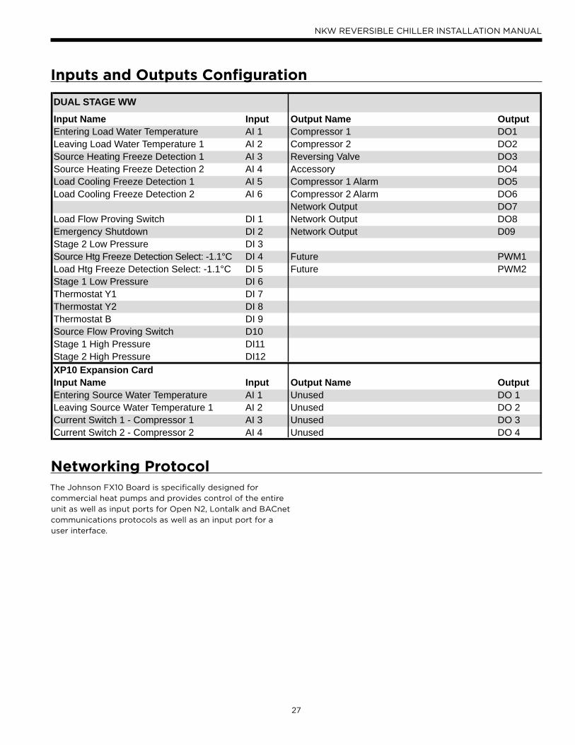
Input Name Input Output Name Output Entering Load Water Temperature AI 1 Compressor 1 DO1Leaving Load Water Temperature 1 AI 2 Compressor 2 DO2Source Heating Freeze Detection 1 AI 3 Reversing Valve DO3Source Heating Freeze Detection 2 AI 4 Accessory DO4Load Cooling Freeze Detection 1 AI 5 Compressor 1 Alarm DO5Load Cooling Freeze Detection 2 AI 6 Compressor 2 Alarm DO6
Network Output DO7Load Flow Proving Switch DI 1 Network Output DO8Emergency Shutdown DI 2 Network Output D09Stage 2 Low Pressure DI 3Source Htg Freeze Detection Select: -1.1°C DI 4 Future PWM1Load Htg Freeze Detection Select: -1.1°C DI 5 Future PWM2Stage 1 Low Pressure DI 6Thermostat Y1 DI 7Thermostat Y2 DI 8Thermostat B DI 9Source Flow Proving Switch D10Stage 1 High Pressure DI11Stage 2 High Pressure DI12XP10 Expansion CardInput Name Input Output Name Output Entering Source Water Temperature AI 1 Unused DO 1Leaving Source Water Temperature 1 AI 2 Unused DO 2Current Switch 1 - Compressor 1 AI 3 Unused DO 3Current Switch 2 - Compressor 2 AI 4 Unused DO 4
Inputs and Outputs Confi guration
The Johnson FX10 Board is specifically designed for
commercial heat pumps and provides control of the entire
unit as well as input ports for Open N2, Lontalk and BACnet
communications protocols as well as an input port for a
user interface.
Networking Protocol
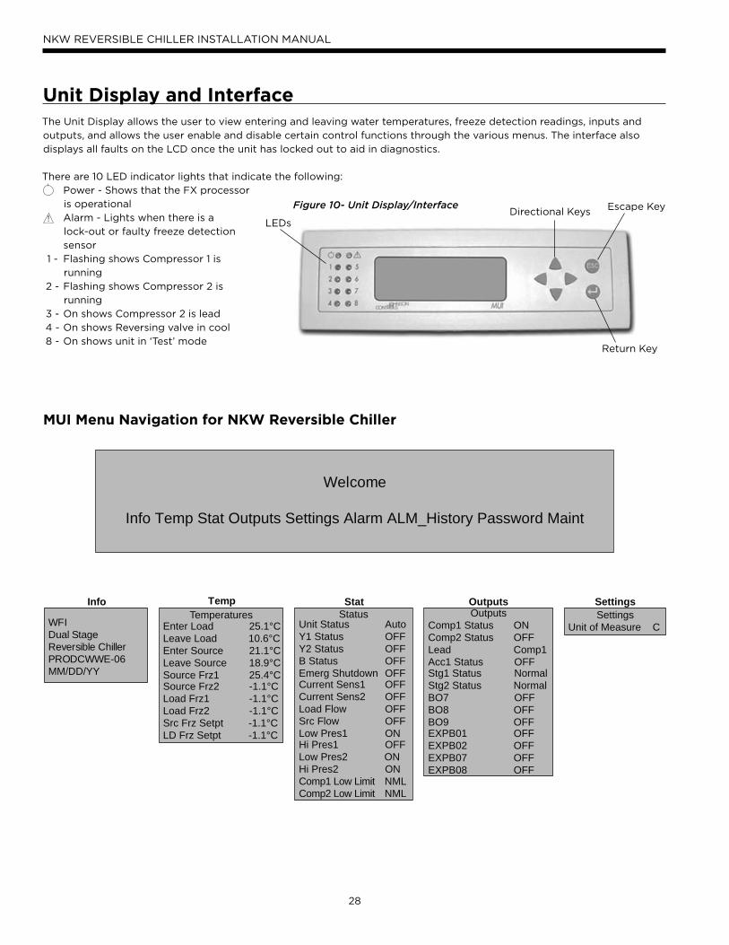
28
NKW REVERSIBLE CHILLER INSTALLATION MANUAL
Unit Display and InterfaceThe Unit Display allows the user to view entering and leaving water temperatures, freeze detection readings, inputs and
outputs, and allows the user enable and disable certain control functions through the various menus. The interface also
displays all faults on the LCD once the unit has locked out to aid in diagnostics.
There are 10 LED indicator lights that indicate the following:
Power - Shows that the FX processor
is operational
Alarm - Lights when there is a
lock-out or faulty freeze detection
sensor
1 - Flashing shows Compressor 1 is
running
2 - Flashing shows Compressor 2 is
running
3 - On shows Compressor 2 is lead
4 - On shows Reversing valve in cool
8 - On shows unit in ‘Test’ mode
Figure 10- Unit Display/Interface Escape Key
Return Key
Directional KeysLEDs!
MUI Menu Navigation for NKW Reversible Chiller
Welcome
Info Temp Stat Outputs Settings Alarm ALM_History Password Maint
WFIDual StageReversible ChillerPRODCWWE-06MM/DD/YY
InfoOutputs
Comp1 Status ONComp2 Status OFFLead Comp1Acc1 Status OFFStg1 Status NormalStg2 Status NormalBO7 OFFBO8 OFFBO9 OFFEXPB01 OFFEXPB02 OFFEXPB07 OFFEXPB08 OFF
OutputsStatus
Unit Status AutoY1 Status OFFY2 Status OFFB Status OFFEmerg Shutdown OFFCurrent Sens1 OFFCurrent Sens2 OFFLoad Flow OFFSrc Flow OFFLow Pres1 ONHi Pres1 OFFLow Pres2 ONHi Pres2 ONComp1 Low Limit NMLComp2 Low Limit NML
StatTemperatures
Enter Load 25.1°CLeave Load 10.6°CEnter Source 21.1°CLeave Source 18.9°CSource Frz1 25.4°CSource Frz2 -1.1°CLoad Frz1 -1.1°CLoad Frz2 -1.1°CSrc Frz Setpt -1.1°CLD Frz Setpt -1.1°C
TempSettings
Unit of Measure C
Settings
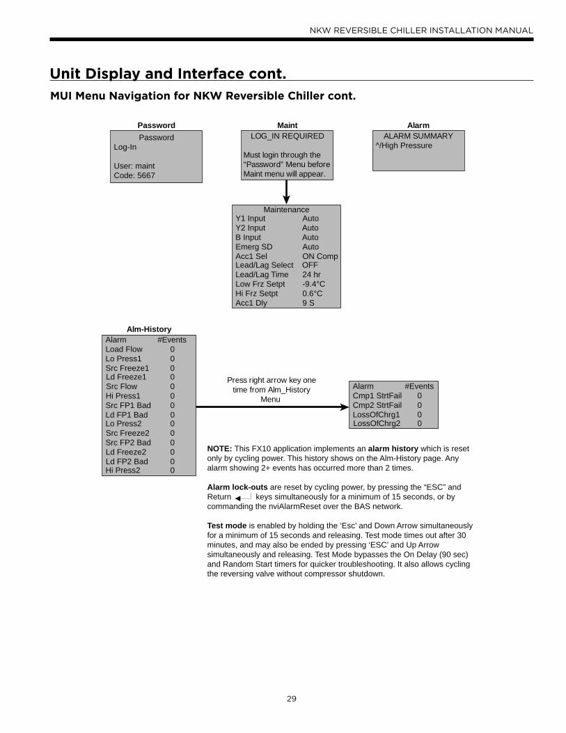
29
NKW REVERSIBLE CHILLER INSTALLATION MANUAL
Unit Display and Interface cont.
MUI Menu Navigation for NKW Reversible Chiller cont.
MaintenanceY1 Input AutoY2 Input AutoB Input AutoEmerg SD AutoAcc1 Sel ON CompLead/Lag Select OFFLead/Lag Time 24 hrLow Frz Setpt -9.4°CHi Frz Setpt 0.6°CAcc1 Dly 9 S
LOG_IN REQUIRED
Must login through the “Password” Menu before Maint menu will appear.
MaintPassword
Log-In
User: maint Code: 5667
PasswordALARM SUMMARY
^/High Pressure
Alarm
NOTE: This FX10 application implements an alarm history which is resetonly by cycling power. This history shows on the Alm-History page. Anyalarm showing 2+ events has occurred more than 2 times.
Alarm lock-outs are reset by cycling power, by pressing the “ESC” andReturn keys simultaneously for a minimum of 15 seconds, or bycommanding the nviAlarmReset over the BAS network.
Test mode is enabled by holding the ‘Esc’ and Down Arrow simultaneouslyfor a minimum of 15 seconds and releasing. Test mode times out after 30minutes, and may also be ended by pressing ‘ESC’ and Up Arrowsimultaneously and releasing. Test Mode bypasses the On Delay (90 sec)and Random Start timers for quicker troubleshooting. It also allows cyclingthe reversing valve without compressor shutdown.
Alarm #EventsLoad Flow 0Lo Press1 0Src Freeze1 0Ld Freeze1 0Src Flow 0Hi Press1 0Src FP1 Bad 0Ld FP1 Bad 0Lo Press2 0Src Freeze2 0Src FP2 Bad 0Ld Freeze2 0Ld FP2 Bad 0Hi Press2 0
Alm-History
Alarm #EventsCmp1 StrtFail 0Cmp2 StrtFail 0LossOfChrg1 0LossOfChrg2 0
Press right arrow key onetime from Alm_History
Menu
30
NKW REVERSIBLE CHILLER INSTALLATION MANUAL
Menu and Menu ContentsAlarm
• Displays unit alarms until the unit has been reset (Unit
alarms can be reset by holding both the Escape (ESC)
key and Return (←) key for five seconds or by power
cycling the unit.)
Alarm History
If a fault occurs the fault will be recorded in history
viewable on the unit mounted display. Each fault type will
be displayed in the history menu with a number between 0
and 3. A reading of 3+ means that the fault has occurred
more than 3 times in the past. The history menu can be
cleared with a power cycle only. Alarm date and time are
not included in the history.
Unit Alarms
Unit alarms are shown on the display once the unit has
locked out.
Load Flow – Load flow switch is not closed
• The load flow switch must be closed prior to either
compressor starting and must remain closed for the
entire run time of the compressor(s).
Low Pressure 1 – Compressor Circuit 1 Low Pressure switch
• The low pressure switch is checked before compressor
start up and is monitored during compressor operation.
Src FP 1 Temp Low – Source Freeze Detection Sensor 1
• The source freeze detection sensor on compressor circuit
1 has reached its setpoint.
Src FP 1 Sensor Bad
• The sensor for Source freeze detection on compressor
circuit 1 is unreliable or is not reading.
LD FP 1 Temp Low – Load Freeze Detection Sensor 1
• The load freeze detection sensor on compressor circuit 1
has reached its setpoint.
LD FP 1 Sensor Bad
• The sensor for Load freeze detection on compressor
circuit 1 is unreliable or is not reading.
Source Flow – Source Flow switch is not closed
• The source flow switch must be closed prior to either
compressor starting and must remain closed for the
entire run-time of the compressor(s).
Unit Display and Interface cont.High Pressure 1 – Compressor Circuit 1 High Pressure Switch
• If high pressure switch 1 opens at any time during
compressor 1 run time the compressor will be shut
down immediately.
Low Pressure 2 - Compressor Circuit 2 Low Pressure Switch
• The low pressure switch is checked before compressor
start up and is monitored during compressor operation.
Src FP 2 Temp Low - Source Freeze Detection Sensor 2
• The source freeze detection sensor on compressor circuit
2 has reached its setpoint.
Src FP 2 Sensor Bad
• The sensor for Source freeze detection on compressor
circuit 2 is unreliable or is not reading.
LD FP 2 Temp Low - Load Freeze Detection Sensor 2
• The load freeze detection sensor on compressor circuit 2
has reached its setpoint.
LD FP 2 Sensor Bad
• The sensor for Load freeze detection on compressor
circuit 2 is unreliable or is not reading.
High Pressure 2 - Compressor Circuit 2 High Pressure Switch
• If high pressure switch 2 opens at any time during
compressor 2 run time the compressor will be shut
down immediately.
Comp Start Failure – Compressor Start Failure
• If either compressor fails to start when the contactor
pulls in the compressor current switch will cause that
compressor to be locked out after 2 retries. The other
compressor will continue to operate normally in
this condition.
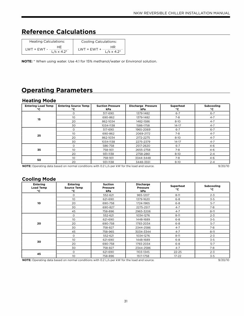
31
NKW REVERSIBLE CHILLER INSTALLATION MANUAL
HE
L/s x 4.2*
Reference CalculationsHeating Calculations: Cooling Calculations:
LWT = EWT + HR
L/s x 4.2*LWT = EWT -
NOTE: * When using water. Use 4.1 for 15% methanol/water or Environol solution.
Operating Parameters
Heating ModeEntering Load Temp
°CEntering Source Temp
°CSuction Pressure
kPaDischarge Pressure
kPaSuperheat
°CSubcooling
°C
15
0 517-690 1379-1482 6-7 6-7
10 690-862 1379-1482 7-8 4-7
20 862-1034 1482-1586 8-10 4-7
30 1034-1138 1586-1758 14-17 4-7
25
0 517-690 1965-2069 6-7 6-7
10 690-862 2069-2172 7-8 4-7
20 862-1034 2172-2275 8-10 4-7
30 1034-1138 2275-2379 14-17 4-7
35
0 586-758 2517-2620 6-7 4-6
10 758-931 2655-2758 7-8 4-6
20 931-1138 2758-2861 8-10 2-4
5010 758-931 3344-3448 7-8 4-6
20 931-1138 3448-3551 8-10 2-4
NOTE: Operating data based on normal conditions with 0.2 L/s per kW for the load and source. 9/20/10
Cooling ModeEntering
Load Temp°C
EnteringSource Temp
°C
SuctionPressure
kPa
Discharge Pressure
kPa
Superheat °C
Subcooling°C
10
0 552-621 965-1207 8-11 2-3
10 621-690 1379-1620 6-8 3-5
20 690-758 1724-1965 6-8 5-7
30 690-827 2275-2517 4-7 7-8
45 758-896 2965-3206 4-7 8-11
20
0 552-621 1034-1276 8-11 2-3
10 621-690 1448-1689 6-8 3-5
20 690-758 1793-2034 6-8 5-7
30 758-827 2344-2586 4-7 7-8
45 758-965 3034-3344 4-7 8-11
30
0 552-621 1034-1276 8-11 2-3
10 621-690 1448-1689 6-8 3-5
20 690-758 1793-2034 6-8 5-7
30 758-827 2344-2586 4-7 7-8
450 621-690 1103-1345 22-25 2-3
10 758-896 1517-1758 17-22 3-5
NOTE: Operating data based on normal conditions with 0.2 L/s per kW for the load and source. 9/20/10
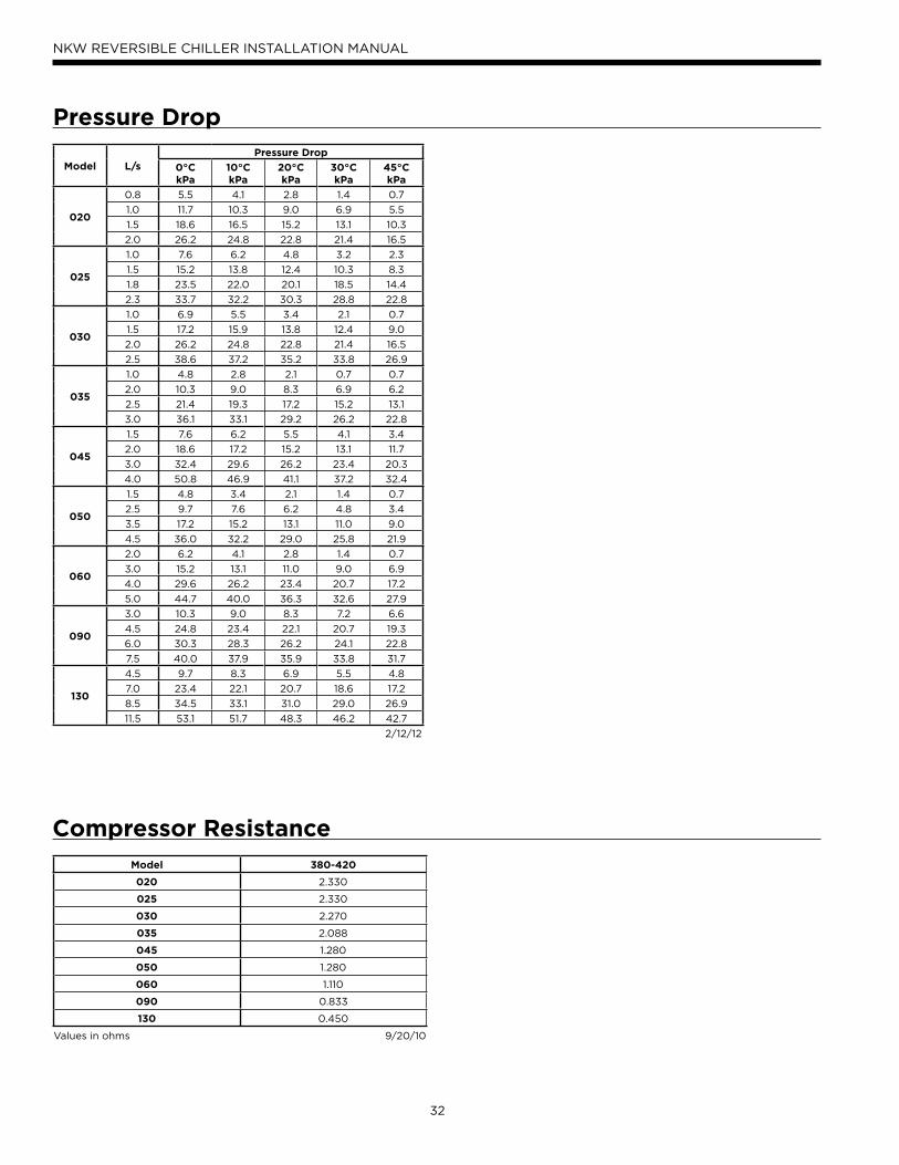
32
NKW REVERSIBLE CHILLER INSTALLATION MANUAL
Compressor ResistanceModel 380-420
020 2.330
025 2.330
030 2.270
035 2.088
045 1.280
050 1.280
060 1.110
090 0.833
130 0.450
Values in ohms 9/20/10
Pressure Drop
Model L/sPressure Drop
0°CkPa
10°CkPa
20°CkPa
30°CkPa
45°CkPa
020
0.8 5.5 4.1 2.8 1.4 0.7
1.0 11.7 10.3 9.0 6.9 5.5
1.5 18.6 16.5 15.2 13.1 10.3
2.0 26.2 24.8 22.8 21.4 16.5
025
1.0 7.6 6.2 4.8 3.2 2.3
1.5 15.2 13.8 12.4 10.3 8.3
1.8 23.5 22.0 20.1 18.5 14.4
2.3 33.7 32.2 30.3 28.8 22.8
030
1.0 6.9 5.5 3.4 2.1 0.7
1.5 17.2 15.9 13.8 12.4 9.0
2.0 26.2 24.8 22.8 21.4 16.5
2.5 38.6 37.2 35.2 33.8 26.9
035
1.0 4.8 2.8 2.1 0.7 0.7
2.0 10.3 9.0 8.3 6.9 6.2
2.5 21.4 19.3 17.2 15.2 13.1
3.0 36.1 33.1 29.2 26.2 22.8
045
1.5 7.6 6.2 5.5 4.1 3.4
2.0 18.6 17.2 15.2 13.1 11.7
3.0 32.4 29.6 26.2 23.4 20.3
4.0 50.8 46.9 41.1 37.2 32.4
050
1.5 4.8 3.4 2.1 1.4 0.7
2.5 9.7 7.6 6.2 4.8 3.4
3.5 17.2 15.2 13.1 11.0 9.0
4.5 36.0 32.2 29.0 25.8 21.9
060
2.0 6.2 4.1 2.8 1.4 0.7
3.0 15.2 13.1 11.0 9.0 6.9
4.0 29.6 26.2 23.4 20.7 17.2
5.0 44.7 40.0 36.3 32.6 27.9
090
3.0 10.3 9.0 8.3 7.2 6.6
4.5 24.8 23.4 22.1 20.7 19.3
6.0 30.3 28.3 26.2 24.1 22.8
7.5 40.0 37.9 35.9 33.8 31.7
130
4.5 9.7 8.3 6.9 5.5 4.8
7.0 23.4 22.1 20.7 18.6 17.2
8.5 34.5 33.1 31.0 29.0 26.9
11.5 53.1 51.7 48.3 46.2 42.7
2/12/12
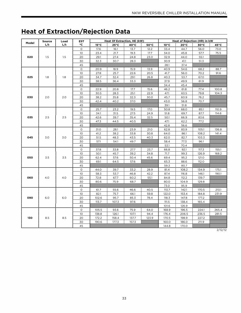
33
NKW REVERSIBLE CHILLER INSTALLATION MANUAL
Heat of Extraction/Rejection Data
ModelSource
L/sLoadL/s
EST ºC
Heat Of Extraction, HE (kW) Heat of Rejection (HR) in kW
15°C 25°C 40°C 50°C 10°C 20°C 30°C 45°C
020 1.5 1.5
0 17.6 16.1 13.7 12.2 33.4 44.7 56.0 73.0
10 23.4 21.7 19.3 17.7 34.0 45.8 57.7 75.5
20 29.1 27.4 24.8 23.0 32.9 44.0 55.1
30 32.3 30.7 28.3 30.9 41.1 51.3
45 28.1 37.4
025 1.8 1.8
0 20.9 18.9 15.9 13.9 40.9 54.6 68.2 88.7
10 27.8 25.7 22.6 20.5 41.7 56.0 70.2 91.6
20 34.7 32.4 29.1 26.8 40.3 53.7 67.0
30 38.5 36.4 33.3 37.9 49.9 61.9
45 34.4 45.4
030 2.0 2.0
0 22.9 20.8 17.7 15.6 46.2 61.8 77.4 100.8
10 30.5 28.3 25.1 22.9 47.1 63.5 79.8 104.3
20 38.2 35.8 32.3 30.0 45.7 60.9 76.2
30 42.4 40.2 37.0 43.0 56.8 70.7
45 39.1 51.8
035 2.5 2.5
0 25.7 23.2 19.5 17.0 50.8 68.0 85.1 110.9
10 34.1 31.5 27.5 24.9 51.8 69.7 87.7 114.6
20 42.6 39.7 35.4 32.5 50.1 66.9 83.6
30 47.3 44.5 40.5 47.1 62.2 77.2
45 42.8 56.6
045 3.0 3.0
0 31.0 28.1 23.9 21.0 62.8 83.9 105.1 136.8
10 41.2 38.2 33.8 30.8 64.0 86.1 108.2 141.4
20 51.5 48.3 43.5 40.3 62.0 82.7 103.3
30 57.1 54.1 49.7 58.4 77.3 96.1
45 53.1 70.4
050 3.5 3.5
0 37.8 33.8 27.7 23.7 66.8 92.1 117.3 155.1
10 50.1 45.7 39.2 34.8 71.7 99.3 126.9 168.2
20 62.4 57.6 50.4 45.6 69.4 95.2 121.0
30 69.1 64.5 57.6 65.3 88.6 112.0
45 59.3 80.7
060 4.0 4.0
0 44.0 39.7 33.2 28.9 81.4 108.2 134.9 175.1
10 58.3 53.7 46.8 42.2 87.4 116.8 146.1 190.1
20 72.8 67.7 60.2 55.1 84.8 112.2 139.7
30 80.6 75.9 68.7 80.0 104.9 129.8
45 73.0 95.9
090 6.0 6.0
0 61.7 55.6 46.6 40.5 113.7 142.1 170.5 213.1
10 82.1 75.7 66.1 59.8 122.0 153.4 184.8 231.9
20 102.6 95.7 85.3 78.4 118.3 147.8 177.2
30 113.7 107.3 97.6 111.5 138.4 165.4
45 101.6 126.9
130 8.5 8.5
0 105.5 93.6 75.9 64.0 168.9 196.5 224.1 265.4
10 138.8 126.1 107.1 94.4 176.4 206.5 236.5 281.5
20 172.2 158.4 137.7 123.9 170.5 198.9 227.2
30 190.6 177.3 157.3 160.0 186.0 211.9
45 144.8 170.0
2/12/12
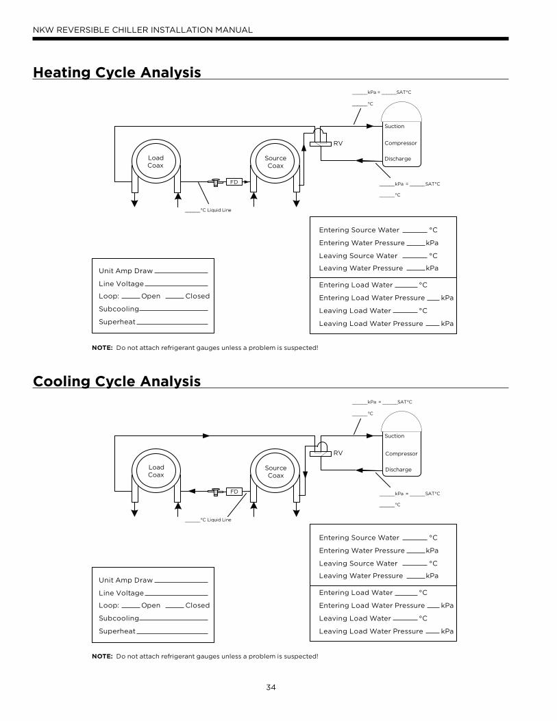
34
NKW REVERSIBLE CHILLER INSTALLATION MANUAL
Heating Cycle Analysis
Suction
Discharge
CompressorRV
SourceCoax
FD
______kPa = ______SAT°C
______°C
______kPa = ______SAT°C
______°C
______°C Liquid Line
Unit Amp Draw
Line Voltage
Loop: Open Closed
Subcooling
Superheat
NOTE: Do not attach refrigerant gauges unless a problem is suspected!
Entering Source Water °C
Entering Water Pressure kPa
Leaving Source Water °C
Leaving Water Pressure kPa
Entering Load Water °C
Entering Load Water Pressure kPa
Leaving Load Water °C
Leaving Load Water Pressure kPa
LoadCoax
Suction
Discharge
CompressorRV
SourceCoax
FD
______kPa = ______SAT°C
______°C
______kPa = ______SAT°C
______°C
______°C Liquid Line
LoadCoax
Unit Amp Draw
Line Voltage
Loop: Open Closed
Subcooling
Superheat
NOTE: Do not attach refrigerant gauges unless a problem is suspected!
Entering Source Water °C
Entering Water Pressure kPa
Leaving Source Water °C
Leaving Water Pressure kPa
Entering Load Water °C
Entering Load Water Pressure kPa
Leaving Load Water °C
Leaving Load Water Pressure kPa
Cooling Cycle Analysis
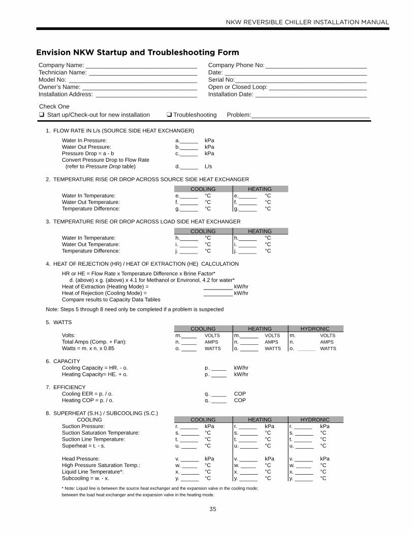
35
NKW REVERSIBLE CHILLER INSTALLATION MANUAL
Check One Start up/Check-out for new installation Troubleshooting Problem:___________________________________
1. FLOW RATE IN L/s (SOURCE SIDE HEAT EXCHANGER)
Water In Pressure: a.______ kPaWater Out Pressure: b.______ kPaPressure Drop = a - b c.______ kPaConvert Pressure Drop to Flow Rate (refer to Pressure Drop table) d.______ L/s
2. TEMPERATURE RISE OR DROP ACROSS SOURCE SIDE HEAT EXCHANGER
COOLING HEATINGWater In Temperature: e.______ °C e.______ °CWater Out Temperature: f. ______ °C f. ______ °CTemperature Difference: g.______ °C g.______ °C
3. TEMPERATURE RISE OR DROP ACROSS LOAD SIDE HEAT EXCHANGER
COOLING HEATINGWater In Temperature: h.______ °C h.______ °CWater Out Temperature: i. ______ °C i. ______ °CTemperature Difference: j. ______ °C j. ______ °C
4. HEAT OF REJECTION (HR) / HEAT OF EXTRACTION (HE) CALCULATION
HR or HE = Flow Rate x Temperature Difference x Brine Factor* d. (above) x g. (above) x 4.1 for Methanol or Environol, 4.2 for water*Heat of Extraction (Heating Mode) = kW/hrHeat of Rejection (Cooling Mode) = kW/hrCompare results to Capacity Data Tables
Note: Steps 5 through 8 need only be completed if a problem is suspected
5. WATTSCOOLING
COOLING
HEATING HYDRONICVolts: m._____ VOLTS m.______ VOLTS m. ______ VOLTSTotal Amps (Comp. + Fan): n. _____ AMPS n. ______ AMPS n. ______ AMPSWatts = m. x n. x 0.85 o. _____ WATTS o. ______ WATTS o. ______ WATTS
6. CAPACITYCooling Capacity = HR. - o. p. _____ kW/hrHeating Capacity= HE. + o. p. _____ kW/hr
7. EFFICIENCYCooling EER = p. / o. q. _____ COPHeating COP = p. / o. q. _____ COP
8. SUPERHEAT (S.H.) / SUBCOOLING (S.C.) COOLING HEATING HYDRONICSuction Pressure: r. ______ kPa r. ______ kPa r. ______ kPaSuction Saturation Temperature: s. ______ °C s. ______ °C s. ______ °CSuction Line Temperature: t. ______ °C t. ______ °C t. ______ °CSuperheat = t. - s. u. _____ °C u. ______ °C u. ______ °C
Head Pressure: v. ______ kPa v. ______ kPa v. ______ kPaHigh Pressure Saturation Temp.: w. _____ °C w. _____ °C w. _____ °CLiquid Line Temperature*: x. ______ °C x. ______ °C x. ______ °CSubcooling = w. - x. y. ______ °C y. ______ °C y. ______ °C
* Note: Liquid line is between the source heat exchanger and the expansion valve in the cooling mode; between the load heat exchanger and the expansion valve in the heating mode.
Company Name: _________________________________Technician Name: ________________________________Model No: ______________________________________Owner’s Name: __________________________________Installation Address: ______________________________
Company Phone No: ______________________________Date: __________________________________________Serial No:_______________________________________Open or Closed Loop: _____________________________Installation Date: _________________________________
Envision NKW Startup and Troubleshooting Form
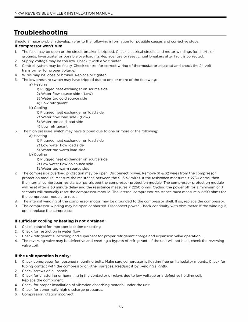
36
NKW REVERSIBLE CHILLER INSTALLATION MANUAL
Should a major problem develop, refer to the following information for possible causes and corrective steps.
If compressor won’t run:
1. The fuse may be open or the circuit breaker is tripped. Check electrical circuits and motor windings for shorts or
grounds. Investigate for possible overloading. Replace fuse or reset circuit breakers after fault is corrected.
2. Supply voltage may be too low. Check it with a volt meter.
3. Control system may be faulty. Check control for correct wiring of thermostat or aquastat and check the 24 volt
transformer for proper voltage.
4. Wires may be loose or broken. Replace or tighten.
5. The low pressure switch may have tripped due to one or more of the following:
a) Heating
1) Plugged heat exchanger on source side
2) Water flow source side -(Low)
3) Water too cold source side
4) Low refrigerant
b) Cooling
1) Plugged heat exchanger on load side
2) Water flow load side - (Low)
3) Water too cold load side
4) Low refrigerant
6. The high pressure switch may have tripped due to one or more of the following:
a) Heating
1) Plugged heat exchanger on load side
2) Low water flow load side
3) Water too warm load side
b) Cooling
1) Plugged heat exchanger on source side
2) Low water flow on source side
3) Water too warm source side
7. The compressor overload protection may be open. Disconnect power. Remove S1 & S2 wires from the compressor
protection module. Measure the resistance between the S1 & S2 wires. If the resistance measures > 2750 ohms, then
the internal compressor resistance has tripped the compressor protection module. The compressor protection module
will reset after a 30 minute delay and the resistance measures < 2250 ohms. Cycling the power off for a minimum of 3
seconds will manually reset the compressor module. The internal compressor resistance must measure < 2250 ohms for
the compressor module to reset.
8. The internal winding of the compressor motor may be grounded to the compressor shell. If so, replace the compressor.
9. The compressor winding may be open or shorted. Disconnect power. Check continuity with ohm meter. If the winding is
open, replace the compressor.
If sufficient cooling or heating is not obtained:
1. Check control for improper location or setting.
2. Check for restriction in water flow.
3. Check refrigerant subcooling and superheat for proper refrigerant charge and expansion valve operation.
4. The reversing valve may be defective and creating a bypass of refrigerant. If the unit will not heat, check the reversing
valve coil.
If the unit operation is noisy:
1. Check compressor for loosened mounting bolts. Make sure compressor is floating free on its isolator mounts. Check for
tubing contact with the compressor or other surfaces. Readjust it by bending slightly.
2. Check screws on all panels.
3. Check for chattering or humming in the contactor or relays due to low voltage or a defective holding coil.
Replace the component.
4. Check for proper installation of vibration absorbing material under the unit.
5. Check for abnormally high discharge pressures.
6. Compressor rotation incorrect
Troubleshooting
37
NKW REVERSIBLE CHILLER INSTALLATION MANUAL
Unit Heat Exchanger Maintenance1. Keep all air out of the water or antifreeze solution.
2. Keep the system under pressure at all times. Closed
loop systems must have positive static pressure or air
vents may draw air into the system.
NOTES: If the installation is in an area with a known high
mineral content in the water, it is best to establish with
the owner a periodic maintenance schedule for checking
the water-to-refrigerant heat exchanger on a regular
basis. Should periodic cleaning be necessary, use standard
cleaning procedures. Generally, the more water flowing
through the unit, the less chance there is for scaling. Low
L/s flow rates produce higher temperatures through the
heat exchanger. To avoid excessive pressure drop and the
possibility of metal erosion, do not exceed L/s flow rate as
shown on the specification sheets for each unit.
Preventive Maintenance
Replacement ProceduresWhen contacting the company for service or replacement
parts, refer to the model number and serial number of the
unit as stamped on the serial plate attached to the unit.
If replacement parts are required, mention the date of
installation of the unit and the date of failure, along with an
explanation of the malfunctions and a description of the
replacement parts required.
In-Warranty Material Return
Material may not be returned except by permission
of authorized warranty personnel. Contact your local
distributor for warranty return authorization and assistance.
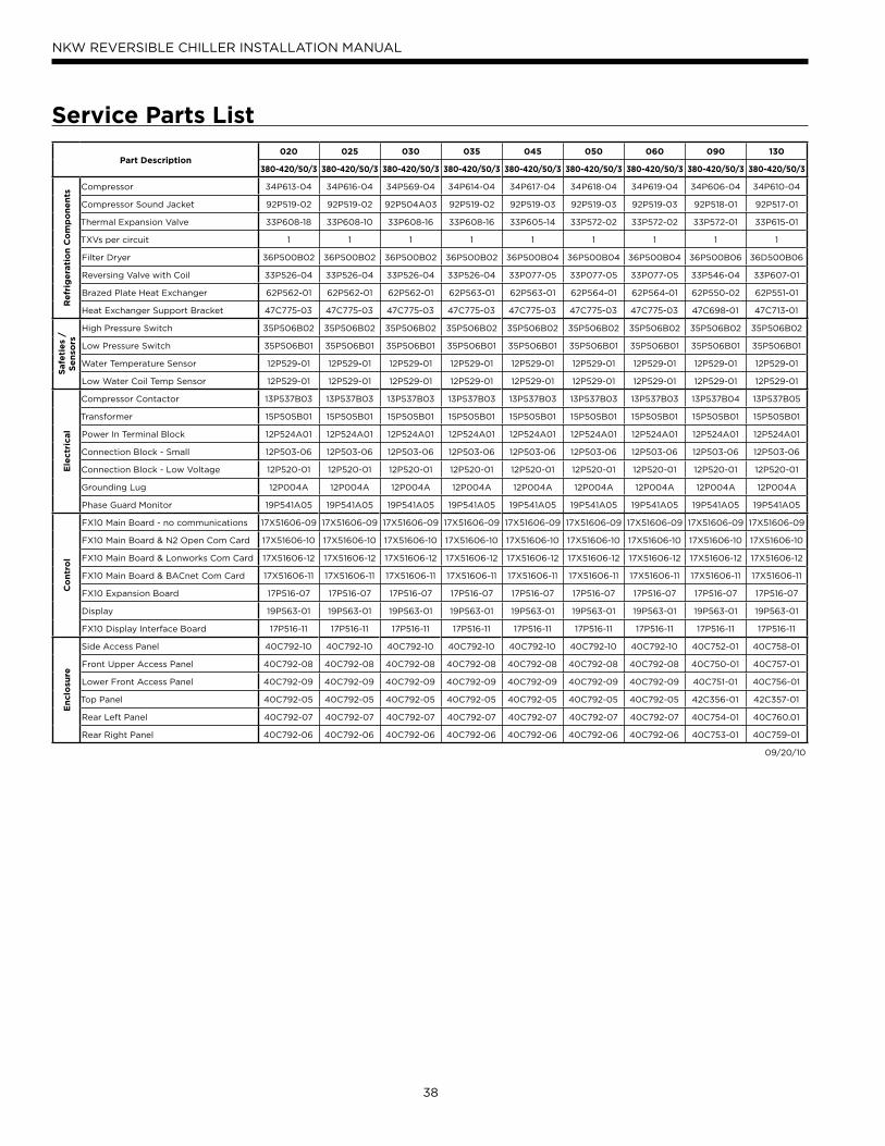
38
NKW REVERSIBLE CHILLER INSTALLATION MANUAL
Service Parts List
Part Description020 025 030 035 045 050 060 090 130
380-420/50/3 380-420/50/3 380-420/50/3 380-420/50/3 380-420/50/3 380-420/50/3 380-420/50/3 380-420/50/3 380-420/50/3
Re
frig
era
tio
n C
om
po
ne
nts
Compressor 34P613-04 34P616-04 34P569-04 34P614-04 34P617-04 34P618-04 34P619-04 34P606-04 34P610-04
Compressor Sound Jacket 92P519-02 92P519-02 92P504A03 92P519-02 92P519-03 92P519-03 92P519-03 92P518-01 92P517-01
Thermal Expansion Valve 33P608-18 33P608-10 33P608-16 33P608-16 33P605-14 33P572-02 33P572-02 33P572-01 33P615-01
TXVs per circuit 1 1 1 1 1 1 1 1 1
Filter Dryer 36P500B02 36P500B02 36P500B02 36P500B02 36P500B04 36P500B04 36P500B04 36P500B06 36D500B06
Reversing Valve with Coil 33P526-04 33P526-04 33P526-04 33P526-04 33P077-05 33P077-05 33P077-05 33P546-04 33P607-01
Brazed Plate Heat Exchanger 62P562-01 62P562-01 62P562-01 62P563-01 62P563-01 62P564-01 62P564-01 62P550-02 62P551-01
Heat Exchanger Support Bracket 47C775-03 47C775-03 47C775-03 47C775-03 47C775-03 47C775-03 47C775-03 47C698-01 47C713-01
Safe
tie
s /
Se
nso
rs
High Pressure Switch 35P506B02 35P506B02 35P506B02 35P506B02 35P506B02 35P506B02 35P506B02 35P506B02 35P506B02
Low Pressure Switch 35P506B01 35P506B01 35P506B01 35P506B01 35P506B01 35P506B01 35P506B01 35P506B01 35P506B01
Water Temperature Sensor 12P529-01 12P529-01 12P529-01 12P529-01 12P529-01 12P529-01 12P529-01 12P529-01 12P529-01
Low Water Coil Temp Sensor 12P529-01 12P529-01 12P529-01 12P529-01 12P529-01 12P529-01 12P529-01 12P529-01 12P529-01
Ele
ctr
ical
Compressor Contactor 13P537B03 13P537B03 13P537B03 13P537B03 13P537B03 13P537B03 13P537B03 13P537B04 13P537B05
Transformer 15P505B01 15P505B01 15P505B01 15P505B01 15P505B01 15P505B01 15P505B01 15P505B01 15P505B01
Power In Terminal Block 12P524A01 12P524A01 12P524A01 12P524A01 12P524A01 12P524A01 12P524A01 12P524A01 12P524A01
Connection Block - Small 12P503-06 12P503-06 12P503-06 12P503-06 12P503-06 12P503-06 12P503-06 12P503-06 12P503-06
Connection Block - Low Voltage 12P520-01 12P520-01 12P520-01 12P520-01 12P520-01 12P520-01 12P520-01 12P520-01 12P520-01
Grounding Lug 12P004A 12P004A 12P004A 12P004A 12P004A 12P004A 12P004A 12P004A 12P004A
Phase Guard Monitor 19P541A05 19P541A05 19P541A05 19P541A05 19P541A05 19P541A05 19P541A05 19P541A05 19P541A05
Co
ntr
ol
FX10 Main Board - no communications 17X51606-09 17X51606-09 17X51606-09 17X51606-09 17X51606-09 17X51606-09 17X51606-09 17X51606-09 17X51606-09
FX10 Main Board & N2 Open Com Card 17X51606-10 17X51606-10 17X51606-10 17X51606-10 17X51606-10 17X51606-10 17X51606-10 17X51606-10 17X51606-10
FX10 Main Board & Lonworks Com Card 17X51606-12 17X51606-12 17X51606-12 17X51606-12 17X51606-12 17X51606-12 17X51606-12 17X51606-12 17X51606-12
FX10 Main Board & BACnet Com Card 17X51606-11 17X51606-11 17X51606-11 17X51606-11 17X51606-11 17X51606-11 17X51606-11 17X51606-11 17X51606-11
FX10 Expansion Board 17P516-07 17P516-07 17P516-07 17P516-07 17P516-07 17P516-07 17P516-07 17P516-07 17P516-07
Display 19P563-01 19P563-01 19P563-01 19P563-01 19P563-01 19P563-01 19P563-01 19P563-01 19P563-01
FX10 Display Interface Board 17P516-11 17P516-11 17P516-11 17P516-11 17P516-11 17P516-11 17P516-11 17P516-11 17P516-11
En
clo
sure
Side Access Panel 40C792-10 40C792-10 40C792-10 40C792-10 40C792-10 40C792-10 40C792-10 40C752-01 40C758-01
Front Upper Access Panel 40C792-08 40C792-08 40C792-08 40C792-08 40C792-08 40C792-08 40C792-08 40C750-01 40C757-01
Lower Front Access Panel 40C792-09 40C792-09 40C792-09 40C792-09 40C792-09 40C792-09 40C792-09 40C751-01 40C756-01
Top Panel 40C792-05 40C792-05 40C792-05 40C792-05 40C792-05 40C792-05 40C792-05 42C356-01 42C357-01
Rear Left Panel 40C792-07 40C792-07 40C792-07 40C792-07 40C792-07 40C792-07 40C792-07 40C754-01 40C760.01
Rear Right Panel 40C792-06 40C792-06 40C792-06 40C792-06 40C792-06 40C792-06 40C792-06 40C753-01 40C759-01
09/20/10
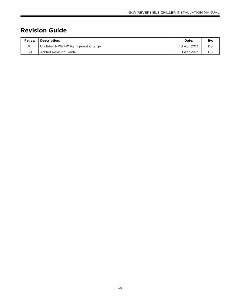
39
NKW REVERSIBLE CHILLER INSTALLATION MANUAL
Revision Guide
Pages: Description: Date: By:
10 Updated NXW140 Refrigerant Charge 10 Apr 2013 DS
39 Added Revision Guide 10 Apr 2013 DS
Manufactured by
WaterFurnace International, Inc.
9000 Conservation Way
Fort Wayne, IN 46809
www.waterfurnace.com
IM1052WN 04/13
Certi cate Number NQA ‘00000028’Factory Standard MCS010Product Standard MCS007
Product: Envision NKW
Type: Commercial Reversible Chiller - 50 Hz
Size: 020-130 kW
Document: Installation Manual
©2013 WaterFurnace International, Inc., 9000 Conservation Way, Fort Wayne, IN 46809-9794. WaterFurnace has a policy of continual product research and development and reserves the right to change design and specifi cations without notice.


![ASTON SERIES GXW CHILLER - Geostar SERIES GXW REVERSIBLE CHILLER SPECIFICATION CATALOG ... formula. This additional ... W_cWR 3\bS`W\U 7\R]]](https://img.pdfslide.us/doc/110x75/5b2c44a57f8b9a163e8bd827/aston-series-gxw-chiller-series-gxw-reversible-chiller-specification-catalog-.jpg)