Embed Size (px)
Citation preview
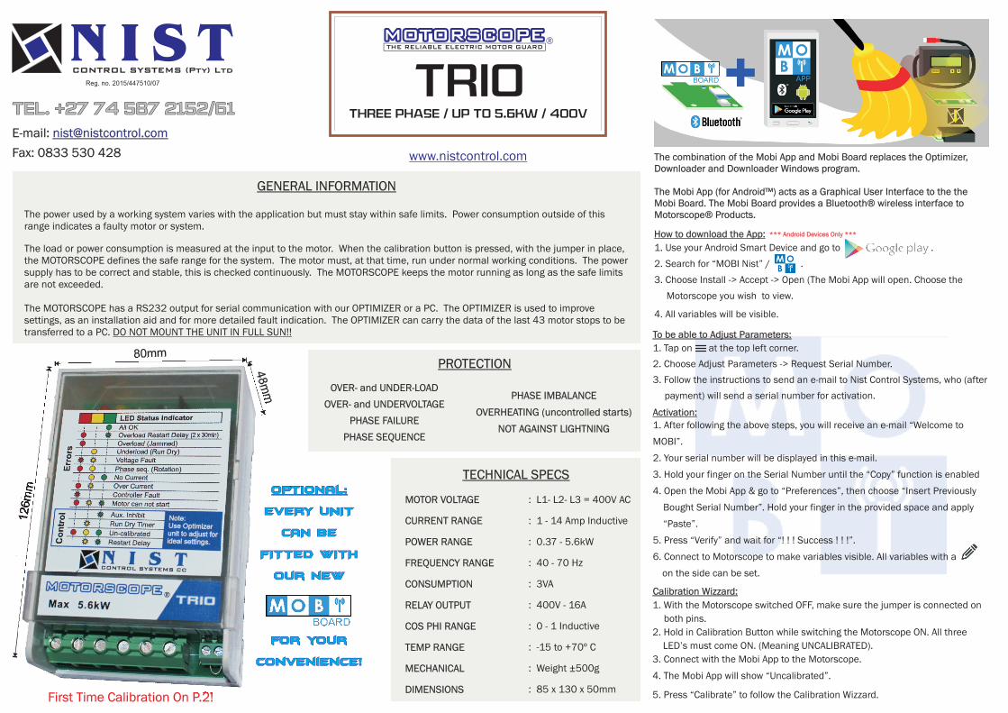
TECHNICAL SPECS
MOTOR VOLTAGE
CURRENT RANGE
POWER RANGE
FREQUENCY RANGE
CONSUMPTION
RELAY OUTPUT
COS PHI RANGE
TEMP RANGE
MECHANICAL
DIMENSIONS
: L1- L2- L3 = 400V AC
: 1 - 14 Amp Inductive
: 0.37 - 5.6kW
: 40 - 70 Hz
: 3VA
: 400V - 16A
: 0 - 1 Inductive
: -15 to +70º C
: Weight ±500g
: 85 x 130 x 50mm
GENERAL INFORMATION
The load or power consumption is measured at the input to the motor. When the calibration button is pressed, with the jumper in place, the MOTORSCOPE defines the safe range for the system. The motor must, at that time, run under normal working conditions. The power supply has to be correct and stable, this is checked continuously. The MOTORSCOPE keeps the motor running as long as the safe limits are not exceeded.
The MOTORSCOPE has a RS232 output for serial communication with our OPTIMIZER or a PC. The OPTIMIZER is used to improve settings, as an installation aid and for more detailed fault indication. The OPTIMIZER can carry the data of the last 43 motor stops to be transferred to a PC. DO NOT MOUNT THE UNIT IN FULL SUN!!
PROTECTION
The power used by a working system varies with the application but must stay within safe limits. Power consumption outside of this range indicates a faulty motor or system.
TrioTHREE PHASE / Up to 5.6kW / 400V
®
OVER- and UNDER-LOAD
OVER- and UNDERVOLTAGE
PHASE FAILURE
PHASE SEQUENCE
PHASE IMBALANCE
OVERHEATING (uncontrolled starts)
NOT AGAINST LIGHTNING
First Time Calibration On P.2!
48m
m
80mm
126m
m
The combination of the Mobi App and Mobi Board replaces the Optimizer, Downloader and Downloader Windows program.
The Mobi App (for Android™) acts as a Graphical User Interface to the the Mobi Board. The Mobi Board provides a Bluetooth® wireless interface to Motorscope® Products.
How to download the App: *** Android Devices Only ***
1. Use your Android Smart Device and go to .
2. Search for “MOBI Nist” / .
3. Choose Install -> Accept -> Open (The Mobi App will open. Choose the
Motorscope you wish to view.
4. All variables will be visible.
To be able to Adjust Parameters:
1. Tap on at the top left corner.
2. Choose Adjust Parameters -> Request Serial Number.
3. Follow the instructions to send an e-mail to Nist Control Systems, who (after
payment) will send a serial number for activation.
Activation:1. After following the above steps, you will receive an e-mail “Welcome to
MOBI”.
2. Your serial number will be displayed in this e-mail.
3. Hold your finger on the Serial Number until the “Copy” function is enabled
4. Open the Mobi App & go to “Preferences”, then choose “Insert Previously
Bought Serial Number”. Hold your finger in the provided space and apply
“Paste”.
5. Press “Verify” and wait for “! ! ! Success ! ! !”.
6. Connect to Motorscope to make variables visible. All variables with a
on the side can be set.
Calibration Wizzard:
1. With the Motorscope switched OFF, make sure the jumper is connected on
both pins.
2. Hold in Calibration Button while switching the Motorscope ON. All three
LED’s must come ON. (Meaning UNCALIBRATED).
3. Connect with the Mobi App to the Motorscope.
4. The Mobi App will show “Uncalibrated”.
5. Press “Calibrate” to follow the Calibration Wizzard.
OPTIONAL:
EVERY UNIT
CAN BE
FITTED WITH
our new
for your
convenience!
Tel. +27 74 587 2152/61
N I S TCONTROL SYSTEMS (Pty) Ltd
Reg. no. 2015/447510/07
E-mail:
Fax: 0833 530 428
www.nistcontrol.com
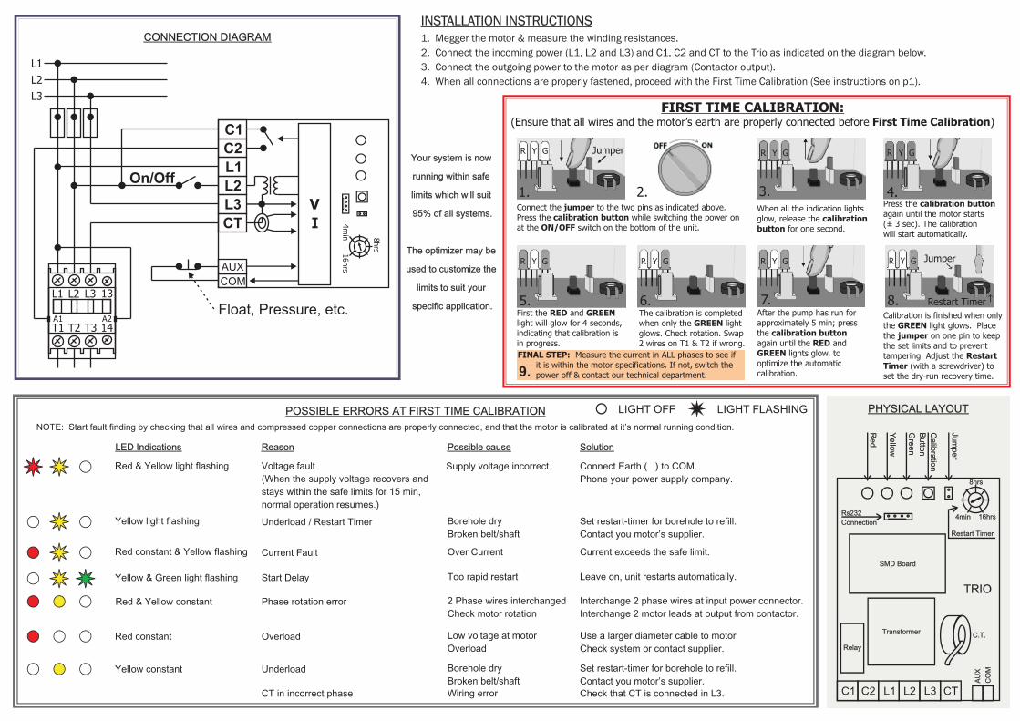
INSTALLATION INSTRUCTIONS1. Megger the motor & measure the winding resistances.
2. Connect the incoming power (L1, L2 and L3) and C1, C2 and CT to the Trio as indicated on the diagram below.
3. Connect the outgoing power to the motor as per diagram (Contactor output).
4. When all connections are properly fastened, proceed with the First Time Calibration (See instructions on p1).
CONNECTION DIAGRAM
T1 T2 T3 14
13L1 L2 L3
A1 A2
L1
L2
L3
C1
C2
L1
L2
L3
CT
AUX
COM
V
On/Off
Float, Pressure, etc.
I 4m
in16hrs
8hrs
LIGHT OFF LIGHT FLASHING
NOTE: Start fault finding by checking that all wires and compressed copper connections are properly connected, and that the motor is calibrated at it’s normal running condition.
Solution
POSSIBLE ERRORS AT FIRST TIME CALIBRATION
Voltage fault
(When the supply voltage recovers and
stays within the safe limits for 15 min,
normal operation resumes.)
Red & Yellow light flashing Supply voltage incorrect Connect Earth ( ) to COM.
Phone your power supply company.
Yellow light flashing Underload / Restart Timer Borehole dry
Broken belt/shaft
Set restart-timer for borehole to refill.
Contact you motor’s supplier.
Red constant & Yellow flashing Current Fault Over Current Current exceeds the safe limit.
Yellow & Green light flashing Start Delay Too rapid restart Leave on, unit restarts automatically.
Red & Yellow constant Phase rotation error 2 Phase wires interchanged
Check motor rotation
Interchange 2 phase wires at input power connector.
Interchange 2 motor leads at output from contactor.
Red constant Overload Low voltage at motor
Overload
Use a larger diameter cable to motor
Check system or contact supplier.
Yellow constant Underload Borehole dry
Broken belt/shaft
Set restart-timer for borehole to refill.
Contact you motor’s supplier.
CT in incorrect phase Wiring error Check that CT is connected in L3.
Reason Possible causeLED Indications
PHYSICAL LAYOUT
8hrs
4min 16hrs
Restart Timer
Rs232
Connection
AU
X
CO
M
C1 C2 L1 L2 L3 CT
TRIO
SMD Board
Transformer
Relay
C.T.
Re
d
Gre
en
Ye
llow
Ca
libra
tion
Bu
tton
Jum
pe
r
Your system is now
running within safe
limits which will suit
95% of all systems.
The optimizer may be
used to customize the
limits to suit your
specific application.
FIRST TIME CALIBRATION: (Ensure that all wires and the motor’s earth are properly connected before First Time Calibration)
When all the indication lightsglow, release the calibrationbutton for one second.
3.
R Y G
Press the calibration button again until the motor starts (± 3 sec). The calibration will start automatically.
4.
R Y G
First the RED and GREEN light will glow for 4 seconds, indicating that calibration is in progress.
5.
R Y G
The calibration is completed when only the GREEN lightglows. Check rotation. Swap2 wires on T1 & T2 if wrong.
6.
R Y G
7.
R Y G
After the pump has run forapproximately 5 min; pressthe calibration button again until the RED and GREEN lights glow, to optimize the automatic calibration.
Jumper
Restart Timer8.
R Y G
Calibration is finished when only the GREEN light glows. Place the jumper on one pin to keep the set limits and to prevent tampering. Adjust the Restart Timer (with a screwdriver) to set the dry-run recovery time.
1.
R Y G Jumper
Connect the jumper to the two pins as indicated above.Press the calibration button while switching the power on at the ON/OFF switch on the bottom of the unit.
2.
9.
FINAL STEP: Measure the current in ALL phases to see if it is within the motor specifications. If not, switch the power off & contact our technical department.