Embed Size (px)
Citation preview
1NION-Autocall AL1500/AC2 Installation/Operation Manual Document 52229 Rev. A 07/19/04
UniNet® 2000NION-AutoCall AL1500/AC2
Instruction Manual
NIO
N-A
uto
Call
A
L1500/A
C2
52020:A ECN 02-232
Document 5222907/19/04 Rev. A
52229:A ECN 03-745
www.PDF-Zoo.com
2 NION-Autocall AL1500/AC2 Installation/Operation Manual Document 52229 Rev. A 07/19/04
Fire Alarm System LimitationsWhile a fire alarm system may lower insurance rates, it is not a substitute for fire insurance!An automatic fire alarm system—typically made up of smoke detectors, heat detectors, manual pull stations, audible warning devices, and a fire alarm control panel with remote notification capability—can provide early warning of a develop-ing fire. Such a system, however, does not assure protection against property damage or loss of life resulting from a fire.
The Manufacturer recommends that smoke and/or heat detec-tors be located throughout a protected premise following the recommendations of the current edition of the National Fire Protection Association Standard 72-1999 (NFPA 72-1999), manufacturer's recommendations, State and local codes, and the recommendations contained in the Guide for Proper Use of System Smoke Detectors, which is made available at no charge to all installing dealers. A study by the Federal Emer-gency Management Agency (an agency of the United States government) indicated that smoke detectors may not go off in as many as 35% of all fires. While fire alarm systems are designed to provide early warning against fire, they do not guarantee warning or protection against fire. A fire alarm sys-tem may not provide timely or adequate warning, or simply may not function, for a variety of reasons:
Smoke detectors may not sense fire where smoke cannot reach the detectors such as in chimneys, in or behind walls, on roofs, or on the other side of closed doors. Smoke detectors also may not sense a fire on another level or floor of a building. A second-floor detector, for example, may not sense a first-floor or basement fire.
Particles of combustion or “smoke” from a developing fire may not reach the sensing chambers of smoke detectors because:
• Barriers such as closed or partially closed doors, walls, or chimneys may inhibit particle or smoke flow.
• Smoke particles may become “cold,” stratify, and not reach the ceiling or upper walls where detectors are located.
• Smoke particles may be blown away from detectors by air outlets.
• Smoke particles may be drawn into air returns before reaching the detector.
The amount of “smoke” present may be insufficient to alarm smoke detectors. Smoke detectors are designed to alarm at various levels of smoke density. If such density levels are not created by a developing fire at the location of detectors, the detectors will not go into alarm.
Smoke detectors, even when working properly, have sensing limitations. Detectors that have photoelectronic sensing chambers tend to detect smoldering fires better than flaming fires, which have little visible smoke. Detectors that have ion-izing-type sensing chambers tend to detect fast-flaming fires better than smoldering fires. Because fires develop in different ways and are often unpredictable in their growth, neither type of detector is necessarily best and a given type of detector may not provide adequate warning of a fire.
Smoke detectors cannot be expected to provide adequate warning of fires caused by arson, children playing with matches (especially in bedrooms), smoking in bed, and violent explosions (caused by escaping gas, improper storage of flammable materials, etc.).
Heat detectors do not sense particles of combustion and alarm only when heat on their sensors increases at a predeter-mined rate or reaches a predetermined level. Rate-of-rise heat detectors may be subject to reduced sensitivity over time. For this reason, the rate-of-rise feature of each detector should be tested at least once per year by a qualified fire pro-tection specialist. Heat detectors are designed to protect property, not life.
IMPORTANT! Smoke detectors must be installed in the same room as the control panel and in rooms used by the sys-tem for the connection of alarm transmission wiring, communi-cations, signaling, and/or power. If detectors are not so located, a developing fire may damage the alarm system, crip-pling its ability to report a fire.
Audible warning devices such as bells may not alert people if these devices are located on the other side of closed or partly open doors or are located on another floor of a building. Any warning device may fail to alert people with a disability or those who have recently consumed drugs, alcohol or medica-tion. Please note that:
• Strobes can, under certain circumstances, cause seizures in people with conditions such as epilepsy.
• Studies have shown that certain people, even when they hear a fire alarm signal, do not respond or comprehend the meaning of the signal. It is the property owner's responsi-bility to conduct fire drills and other training exercise to make people aware of fire alarm signals and instruct them on the proper reaction to alarm signals.
• In rare instances, the sounding of a warning device can cause temporary or permanent hearing loss.
A fire alarm system will not operate without any electrical power. If AC power fails, the system will operate from standby batteries only for a specified time and only if the batteries have been properly maintained and replaced regularly.
Equipment used in the system may not be technically com-patible with the control panel. It is essential to use only equip-ment listed for service with your control panel.
Telephone lines needed to transmit alarm signals from a premise to a central monitoring station may be out of service or temporarily disabled. For added protection against tele-phone line failure, backup radio transmission systems are rec-ommended.
The most common cause of fire alarm malfunction is inade-quate maintenance. To keep the entire fire alarm system in excellent working order, ongoing maintenance is required per the manufacturer's recommendations, and UL and NFPA stan-dards. At a minimum, the requirements of Chapter 7 of NFPA 72-1999 shall be followed. Environments with large amounts of dust, dirt or high air velocity require more frequent mainte-nance. A maintenance agreement should be arranged through the local manufacturer's representative. Maintenance should be scheduled monthly or as required by National and/or local fire codes and should be performed by authorized pro-fessional fire alarm installers only. Adequate written records of all inspections should be kept.
Precau-L-1-2004.fm
www.PDF-Zoo.com
3NION-Autocall AL1500/AC2 Installation/Operation Manual Document 52229 Rev. A 07/19/04
Installation PrecautionsAdherence to the following will aid in problem-free installation with long-term reliability:WARNING - Several different sources of power can be connected to the fire alarm control panel. Disconnect all sources of power before servicing. The control unit and asso-ciated equipment may be damaged by removing and/or insert-ing cards, modules, or interconnecting cables while the unit is energized. Do not attempt to install, service, or operate this unit until this manual is read and understood.
CAUTION - System Reacceptance Test after Software Changes. To ensure proper system operation, this product must be tested in accordance with NFPA 72-1999 Chapter 7 after any programming operation or change in site-specific software. Reacceptance testing is required after any change, addition or deletion of system components, or after any modifi-cation, repair or adjustment to system hardware or wiring.
All components, circuits, system operations, or software func-tions known to be affected by a change must be 100% tested. In addition, to ensure that other operations are not inadvert-ently affected, at least 10% of initiating devices that are not directly affected by the change, up to a maximum of 50 devices, must also be tested and proper system operation ver-ified.
This system meets NFPA requirements for operation at 0°C to 49°C (32°F to 120°F) and at a relative humidity (noncon-densing) of 85% at 30°C (86°F) per NFPA, and 93% ± 2% at 32°C ± 2°C (89.6°F ± 1.1°F) per ULC. However, the useful life of the system's standby batteries and the electronic compo-nents may be adversely affected by extreme temperature ranges and humidity. Therefore, it is recommended that this system and all peripherals be installed in an environment with a nominal room temperature of 15-27° C/60-80° F.
Verify that wire sizes are adequate for all initiating and indi-cating device loops. Most devices cannot tolerate more than a 10% I.R. drop from the specified device voltage.
Like all solid state electronic devices, this system may operate erratically or can be damaged when subjected to light-ning-induced transients. Although no system is completely immune from lightning transients and interferences, proper grounding will reduce susceptibility. Overhead or outside aerial wiring is not recommended, due to an increased sus-ceptibility to nearby lightning strikes. Consult with the Techni-cal Services Department if any problems are anticipated or encountered.
Disconnect AC power and batteries prior to removing or inserting circuit boards. Failure to do so can damage circuits.
Remove all electronic assemblies prior to any drilling, filing, reaming, or punching of the enclosure. When possible, make all cable entries from the sides or rear. Before making modifi-cations, verify that they will not interfere with battery, trans-former, and printed circuit board location.
Do not tighten screw terminals more than 9 in-lbs. Over-tightening may damage threads, resulting in reduced ter-minal contact pressure and difficulty with screw terminal removal.
Though designed to last many years, system components can fail at any time. This system contains static-sensitive components. Always ground yourself with a proper wrist strap before handling any circuits so that static charges are removed from the body. Use static-suppressive packaging to protect electronic assemblies removed from the unit.
Follow the instructions in the installation, operating, and pro-gramming manuals. These instructions must be followed to avoid damage to the control panel and associated equipment. FACP operation and reliability depend upon proper installation by authorized personnel.
Precau-L-10-2003.fm
FCC WarningWARNING: This equipment generates, uses, and can radiate radio frequency energy and if not installed and used in accordance with the instruction manual, may cause interference to radio communications. It has been tested and found to comply with the limits for class A computing device pursuant to Subpart B of Part 15 of FCC Rules, which is designed to provide reasonable protection against such interference when operated in a commercial environment. Operation of this equipment in a residential area is likely to cause interference, in which case the user will be required to correct the interference at his own expense.
Canadian RequirementsThis digital apparatus does not exceed the Class A limits for radiation noise emissions from digital apparatus set out in the Radio Interference Regulations of the Cana-dian Department of Communications.
Le present appareil numerique n'emet pas de bruits radi-oelectriques depassant les limites applicables aux appa-reils numeriques de la classe A prescrites dans le Reglement sur le brouillage radioelectrique edicte par le ministere des Communications du Canada.
Acclimate Plus™, AWACS™, HARSH™, NOTI•FIRE•NET™, and VeriFire™ are trademarks, and ONYX®, FlashScan®, UniNet®, and VIEW® are registeredtrademarks of NOTIFIER. NION™ is a trademark of NIS. NIS™ and Notifier Integrated Systems™ are trademarks and NOTIFIER® is a registered trademarkof Fire•Lite Alarms, Inc. Echelon® is a registered trademark and LonWorks™ is a trademark of Echelon Corporation. ARCNET® is a registered trademark ofDatapoint Corporation. Microsoft® and Windows® are registered trademarks of the Microsoft Corporation. LEXAN® is a registered trademark of GE Plastics,a subsidiary of General Electric Company.
www.PDF-Zoo.com

4 NION-Autocall AL1500/AC2 Installation/Operation Manual Document 52229 Rev. A 07/19/04
www.PDF-Zoo.com
www.PD
5NION-Autocall AL1500/AC2 Installation/Operation Manual Document 52229 Rev. A 07/19/04
Section 1: NION-AutoCall AL1500/AC2 Hardware ................................................91.1 General Description .................................................................................................................. 91.2 Hardware Description................................................................................................................ 91.3 NION-NPB Board Layout ........................................................................................................ 10
Figure 1-1: NION-NPB Board Layout ................................................................................................... 101.4 NISCAB-1 NION Enclosure Installation ................................................................................... 12
Figure 1-2: NISCAB-1 Enclosure Mounting Hole Layout.......................................................................... 12Figure 1-3: NION Mounting Stud Locations........................................................................................... 13
1.5 NION Hardware Connections................................................................................................. 131.6 NION Hardware Connections - SMX Network Connection........................................................ 14
Figure 1-4: FTXC Network Transceiver .................................................................................................. 15Figure 1-5: S7FTXC Style 7 Transceiver ................................................................................................. 15Figure 1-6: Sample Style 7 Networks..................................................................................................... 16Figure 1-7: FOXC and DFXC Fiber Optic Network Transceivers............................................................... 16
1.7 NION Hardware Connections - Serial Data Connection .......................................................... 17Figure 1-8: AutoCall Serial Connections................................................................................................ 17
1.8 NION Hardware Connections - Power Connection.................................................................. 17Figure 1-9: NION-NPB TB5 Power Connection...................................................................................... 17
1.9 Relay Output - Fault Annunciation .......................................................................................... 17Figure 1-10: NION Fault Annunciation ................................................................................................. 17
1.10 Software Replacement/Upgrade Installation.......................................................................... 18Figure 1-11: NION Software Replacement ............................................................................................ 18
1.11 Adding and Binding the NION-AutoCall AL1500/AC2............................................................ 19Figure 1-12: Adding And Binding A NION ............................................................................................ 19
Section 2: NION-AutoCall AL1500/AC2 Explorer.................................................212.1 AutoCall Explorer Overview ..................................................................................................... 212.2 Registering and Opening the AutoCall Explorer........................................................................ 21
Figure 2-1: NION-AutoCall AL1500/AC2 Right Click Menu ................................................................... 212.3 Initial Events From AutoCall Panel Devices ............................................................................... 212.4 The AutoCall Explorer Main Form ............................................................................................ 22
Figure 2-2: The AutoCall Explorer Main Screen...................................................................................... 222.5 NION Configuration through AutoCall Explorer ....................................................................... 23
Contents
F-Zoo.com

www
6 NION-Autocall AL1500/AC2 Installation/Operation Manual Document 52229 Rev. A 07/19/04
.PDF-Zoo.com
7NION-Autocall AL1500/AC2 Installation/Operation Manual Document 52229 Rev. A 07/19/04
ForewordThe contents of this manual are important and must be kept in close proximity of the hardware. If building ownership is changed, this manual and all other testing and maintenance information must also be passed to the current owner of the facility. A copy of this manual was shipped with the equipment and is also available from the manufacturer.
This equipment has been designed to comply with standards set forth by the following regulatory agencies:• National Fire Protection Association Standards 72.
• National Electric Code (NFPA 70).
• Life Safety Code (NFPA 101).
• Requirements of the Local Authority Having Jurisdiction (LAHJ).
IntroductionThe NION-AutoCall AL1500/AC2 is a plug-in component of the UniNet® 2000 Workstation. It allows a workstation to view events and other data originating from an AutoCall fire panel.
This system is suitable for proprietary systems listed under:• NFPA 72-1993 Proprietary Service.
UniNet® 2000 consists of graphical workstations monitoring and controlling local or remote twisted pair or fiber optic networks. Remote network monitoring is achieved through the use of a Building Communications Interface (BCI), which has a maximum capacity of 32 nodes. Each Local Area Server (LAS) has a maximum capacity of 200 nodes, using twisted pair or fiber-optic cabling. A twisted pair network topology (FT-10) may be a maximum length of 6000 feet per network segment with no T-taps, allowing communications between 64 nodes in each segment. In addition, FT-10 allows dedicated runs of 8000 feet point-to-point or multiple T-taps within 1500 feet of any other node on the segment. Fiber-optic cable runs can be configured in either a bus or ring topology. The network is supervised for shorts, opens and node failures as dictated in Style 4, 6 and 7 wiring.
The network power is 24 VDC nominal and receives operating power from a power limited, filtered source listed for use with fire protective signaling units.
WARNING: Improper installation, maintenance, and lack of routine testing could result in system malfunction.
www.PDF-Zoo.com
8 NION-Autocall AL1500/AC2 Installation/Operation Manual Document 52229 Rev. A 07/19/04
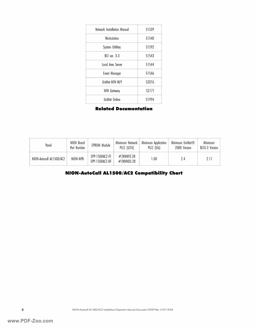
Related Documentation
NION-AutoCall AL1500/AC2 Compatibility Chart
Panel NION BoardPart Number EPROM Module Minimum Network
PLCC (U24)Minimum Application
PLCC (U6)Minimum UniNet®
2000 VersionMinimum
BCI3-3 Version
NION-Autocall AL1500/AC2 NION-NPB EPP-1500AC2-FTEPP-1500AC2-DF
#2KNNF3.28#2KNND3.28 1.00 2.4 2.11
Network Installation Manual 51539
Workstation 51540
System Utilities 51592
BCI ver. 3-3 51543
Local Area Server 51544
Event Manager 51546
UniNet-NFN-W/F 52076
NFN Gateway 52171
UniNet Online 51994
www.PDF-Zoo.com
www.PD
9NION-Autocall AL1500/AC2 Installation/Operation Manual Document 52229 Rev. A 07/19/04
Section 1: NION-AutoCall AL1500/AC2 Hardware1.1 General Description
Required Equipment• NION-NPB PC board• SMX Network Transceiver (FTXC, S7FTXC, FOXC or DFXC)• Software kit for the AutoCall NION (EPP-1500AC2-FT/DF)
• NISCAB-1 Cabinet• Serial Interface Cable (supplied by customer)
1.2 Hardware Description
NION-AutoCall AL1500/AC2 Motherboard
The NION-NPB (Network Input Output Node) is an EIA-232 protocol conversion platform. All of the system compo-nents are based on LonWorks™ (Local Operating Network) technologies. The NION-AutoCall AL1500/AC2 pro-vides transparent or interpreted communications between the workstation and control panel.
The NION connects a LonWorks™ wire or fiber optic network to a fire alarm control panel through the EIA-232 port of the control panel. It provides a single, two-way communication channel for EIA-232 serial data when connected to a control panel. NIONs are specific to the type of network to which they connect (wire or fiber). The LonWorks™ net-work interface accepts any standard SMX style transceiver (FTXC, S7FTXC, FOXC, or DFXC). The transceiver type must be specified and ordered separately when ordering the AutoCall NION.
The NION mounts in an enclosure (NISCAB-1) with conduit knockout.
Site Requirements
The NION-AutoCall AL1500/AC2 must be installed in the following environmental conditions:• Temperature range of 0°C to 49°C (32°F - 120°F).
• 93% humidity non-condensing at 30°C (86°F).
Mounting
The NION-AutoCall AL1500/AC2 is designed for wall installation with wiring in conduit within 20 feet of the control panel in the same room. The type of hardware used is at the discretion of the installer but must be in accordance with local code requirements.
1
F-Zoo.com
www
10 NION-Autocall AL1500/AC2 Installation/Operation Manual Document 52229 Rev. A 07/19/04
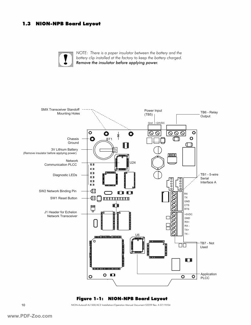
1.3 NION-NPB Board Layout
Figure 1-1: NION-NPB Board Layout
Power Input(TB5) TB6 - Relay
Output
Gnd +24VDC
SMX Transceiver StandoffMounting Holes
ChassisGround
3V Lithium Battery(Remove insulator before applying power)
NetworkCommunication PLCC U24
BT1
U6
Diagnostic LEDs
SW2 Network Binding Pin
SW1 Reset Button
J1 Header for EchelonNetwork Transceiver
TB1 - 5-wireSerialInterface A
RXTXGNDCTSRTS
+5VDCGNDRX+RX -TX+TX -
TB7 - NotUsed
ApplicationPLCC
NOTE: There is a paper insulator between the battery and the battery clip installed at the factory to keep the battery charged. Remove the insulator before applying power.
.PDF-Zoo.com
www.PD
11NION-Autocall AL1500/AC2 Installation/Operation Manual Document 52229 Rev. A 07/19/04
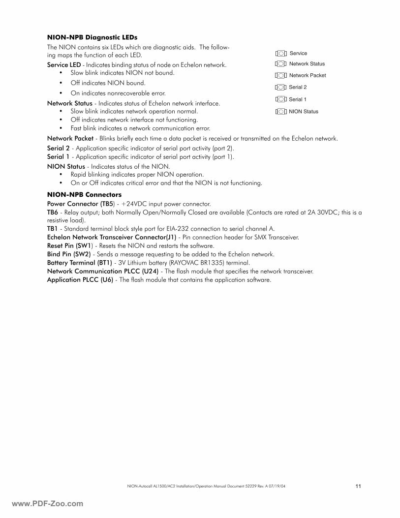
NION-NPB Diagnostic LEDs
The NION contains six LEDs which are diagnostic aids. The follow-ing maps the function of each LED.
Service LED - Indicates binding status of node on Echelon network. • Slow blink indicates NION not bound.
• Off indicates NION bound.
• On indicates nonrecoverable error.
Network Status - Indicates status of Echelon network interface. • Slow blink indicates network operation normal.• Off indicates network interface not functioning.• Fast blink indicates a network communication error.
Network Packet - Blinks briefly each time a data packet is received or transmitted on the Echelon network.
Serial 2 - Application specific indicator of serial port activity (port 2). Serial 1 - Application specific indicator of serial port activity (port 1).
NION Status - Indicates status of the NION.• Rapid blinking indicates proper NION operation.• On or Off indicates critical error and that the NION is not functioning.
NION-NPB ConnectorsPower Connector (TB5) - +24VDC input power connector.TB6 - Relay output; both Normally Open/Normally Closed are available (Contacts are rated at 2A 30VDC; this is a resistive load).TB1 - Standard terminal block style port for EIA-232 connection to serial channel A.Echelon Network Transceiver Connector(J1) - Pin connection header for SMX Transceiver.Reset Pin (SW1) - Resets the NION and restarts the software.Bind Pin (SW2) - Sends a message requesting to be added to the Echelon network.Battery Terminal (BT1) - 3V Lithium battery (RAYOVAC BR1335) terminal.Network Communication PLCC (U24) - The flash module that specifies the network transceiver.Application PLCC (U6) - The flash module that contains the application software.
Service
Network Status
Network Packet
Serial 2
Serial 1
NION Status
F-Zoo.com
www
12 NION-Autocall AL1500/AC2 Installation/Operation Manual Document 52229 Rev. A 07/19/04
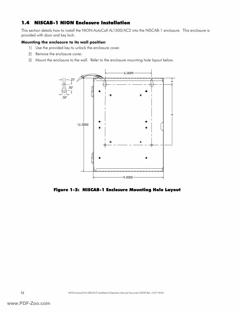
1.4 NISCAB-1 NION Enclosure Installation
This section details how to install the NION-AutoCall AL1500/AC2 into the NISCAB-1 enclosure. This enclosure is provided with door and key lock.
Mounting the enclosure to its wall position1) Use the provided key to unlock the enclosure cover.
2) Remove the enclosure cover.
3) Mount the enclosure to the wall. Refer to the enclosure mounting hole layout below.
Figure 1-2: NISCAB-1 Enclosure Mounting Hole Layout
.25"
.50"
.50"
12.0000
9.0000
6.0009
.PDF-Zoo.com
www.PD
13NION-Autocall AL1500/AC2 Installation/Operation Manual Document 52229 Rev. A 07/19/04
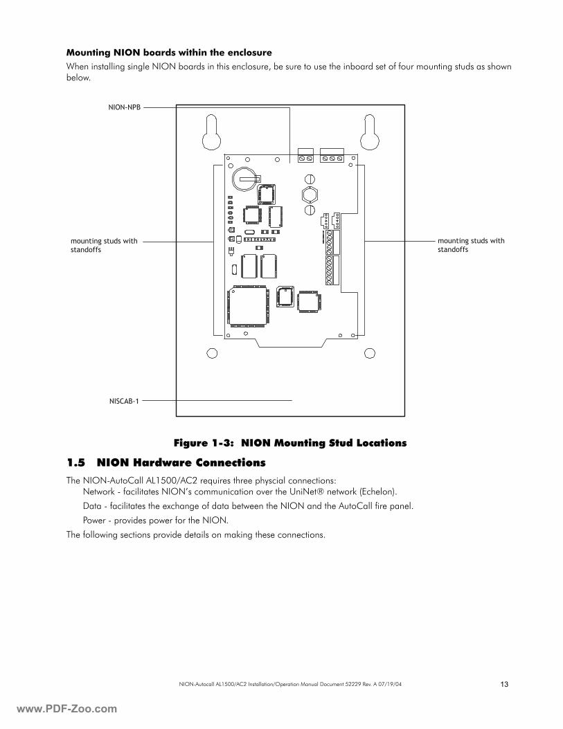
Mounting NION boards within the enclosure
When installing single NION boards in this enclosure, be sure to use the inboard set of four mounting studs as shown below.
Figure 1-3: NION Mounting Stud Locations
1.5 NION Hardware Connections
The NION-AutoCall AL1500/AC2 requires three physcial connections:Network - facilitates NION’s communication over the UniNet® network (Echelon).
Data - facilitates the exchange of data between the NION and the AutoCall fire panel.
Power - provides power for the NION.
The following sections provide details on making these connections.
NION-NPB
mounting studs withstandoffs
mounting studs withstandoffs
NISCAB-1
F-Zoo.com
www
14 NION-Autocall AL1500/AC2 Installation/Operation Manual Document 52229 Rev. A 07/19/04
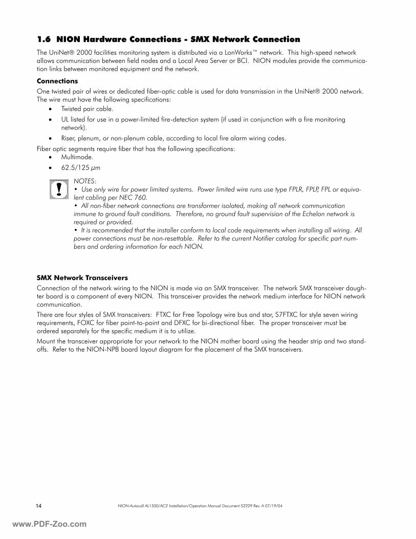
1.6 NION Hardware Connections - SMX Network Connection
The UniNet® 2000 facilities monitoring system is distributed via a LonWorks™ network. This high-speed network allows communication between field nodes and a Local Area Server or BCI. NION modules provide the communica-tion links between monitored equipment and the network.
Connections
One twisted pair of wires or dedicated fiber-optic cable is used for data transmission in the UniNet® 2000 network.The wire must have the following specifications:
• Twisted pair cable.
• UL listed for use in a power-limited fire-detection system (if used in conjunction with a fire monitoring network).
• Riser, plenum, or non-plenum cable, according to local fire alarm wiring codes.
Fiber optic segments require fiber that has the following specifications:• Multimode.
• 62.5/125 µm
SMX Network Transceivers
Connection of the network wiring to the NION is made via an SMX transceiver. The network SMX transceiver daugh-ter board is a component of every NION. This transceiver provides the network medium interface for NION network communication.
There are four styles of SMX transceivers: FTXC for Free Topology wire bus and star, S7FTXC for style seven wiring requirements, FOXC for fiber point-to-point and DFXC for bi-directional fiber. The proper transceiver must be ordered separately for the specific medium it is to utilize.
Mount the transceiver appropriate for your network to the NION mother board using the header strip and two stand-offs. Refer to the NION-NPB board layout diagram for the placement of the SMX transceivers.
NOTES:• Use only wire for power limited systems. Power limited wire runs use type FPLR, FPLP, FPL or equiva-lent cabling per NEC 760.• All non-fiber network connections are transformer isolated, making all network communication immune to ground fault conditions. Therefore, no ground fault supervision of the Echelon network is required or provided.• It is recommended that the installer conform to local code requirements when installing all wiring. All power connections must be non-resettable. Refer to the current Notifier catalog for specific part num-bers and ordering information for each NION.
.PDF-Zoo.com
www.PD
15NION-Autocall AL1500/AC2 Installation/Operation Manual Document 52229 Rev. A 07/19/04
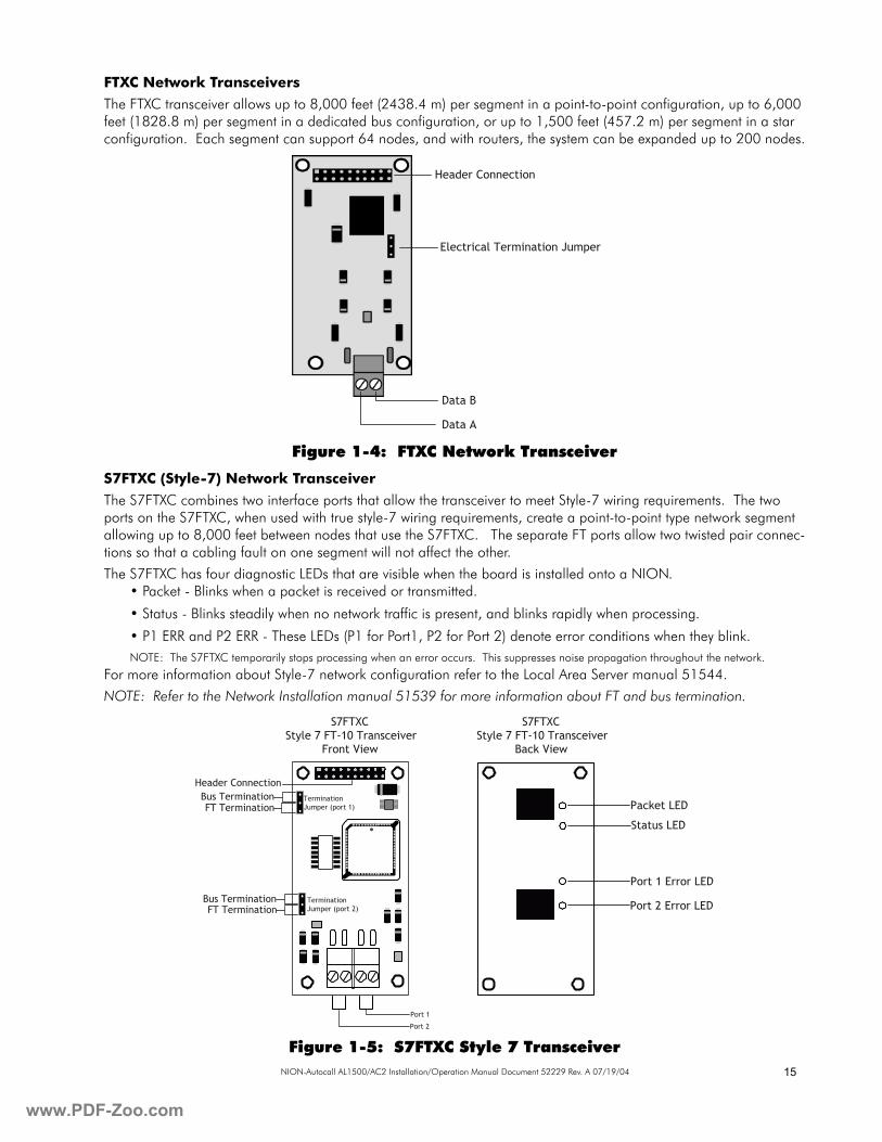
FTXC Network Transceivers
The FTXC transceiver allows up to 8,000 feet (2438.4 m) per segment in a point-to-point configuration, up to 6,000 feet (1828.8 m) per segment in a dedicated bus configuration, or up to 1,500 feet (457.2 m) per segment in a star configuration. Each segment can support 64 nodes, and with routers, the system can be expanded up to 200 nodes.
Figure 1-4: FTXC Network Transceiver
S7FTXC (Style-7) Network Transceiver
The S7FTXC combines two interface ports that allow the transceiver to meet Style-7 wiring requirements. The two ports on the S7FTXC, when used with true style-7 wiring requirements, create a point-to-point type network segment allowing up to 8,000 feet between nodes that use the S7FTXC. The separate FT ports allow two twisted pair connec-tions so that a cabling fault on one segment will not affect the other.
The S7FTXC has four diagnostic LEDs that are visible when the board is installed onto a NION.• Packet - Blinks when a packet is received or transmitted.
• Status - Blinks steadily when no network traffic is present, and blinks rapidly when processing.
• P1 ERR and P2 ERR - These LEDs (P1 for Port1, P2 for Port 2) denote error conditions when they blink.NOTE: The S7FTXC temporarily stops processing when an error occurs. This suppresses noise propagation throughout the network.
For more information about Style-7 network configuration refer to the Local Area Server manual 51544.
NOTE: Refer to the Network Installation manual 51539 for more information about FT and bus termination.
Figure 1-5: S7FTXC Style 7 Transceiver
Header Connection
Electrical Termination Jumper
Data B
Data A
S7FTXCStyle 7 FT-10 Transceiver
Front View
Header ConnectionBus TerminationFT Termination
TerminationJumper (port 1)
TerminationJumper (port 2)
Bus TerminationFT Termination
Port 1
Port 2
S7FTXCStyle 7 FT-10 Transceiver
Back View
Packet LED
Status LED
Port 1 Error LED
Port 2 Error LED
F-Zoo.com
www
16 NION-Autocall AL1500/AC2 Installation/Operation Manual Document 52229 Rev. A 07/19/04
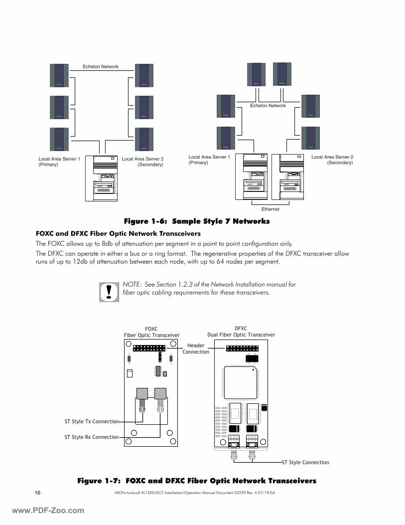
Figure 1-6: Sample Style 7 Networks
FOXC and DFXC Fiber Optic Network Transceivers
The FOXC allows up to 8db of attenuation per segment in a point to point configuration only.
The DFXC can operate in either a bus or a ring format. The regenerative properties of the DFXC transceiver allow runs of up to 12db of attenuation between each node, with up to 64 nodes per segment.
Figure 1-7: FOXC and DFXC Fiber Optic Network Transceivers
NOTIFIER
NOTIFIER
NOTIFIER
NOTIFIER
NOTIFIER
NOTIFIER
Echelon Network
Local Area Server 2(Secondary)
Local Area Server 1(Primary)
NOTIFIER
NOTIFIER
NOTIFIER
NOTIFIER
NOTIFIER
NOTIFIER
Echelon Network
Local Area Server 2(Secondary)
Local Area Server 1(Primary)
Ethernet
NOTE: See Section 1.2.3 of the Network Installation manual for fiber optic cabling requirements for these transceivers.
FOXCFiber Optic Transceiver
DFXCDual Fiber Optic Transceiver
HeaderConnection
ST Style Rx Connection
ST Style Tx Connection
ST Style Connection
.PDF-Zoo.com
www.PD
17NION-Autocall AL1500/AC2 Installation/Operation Manual Document 52229 Rev. A 07/19/04
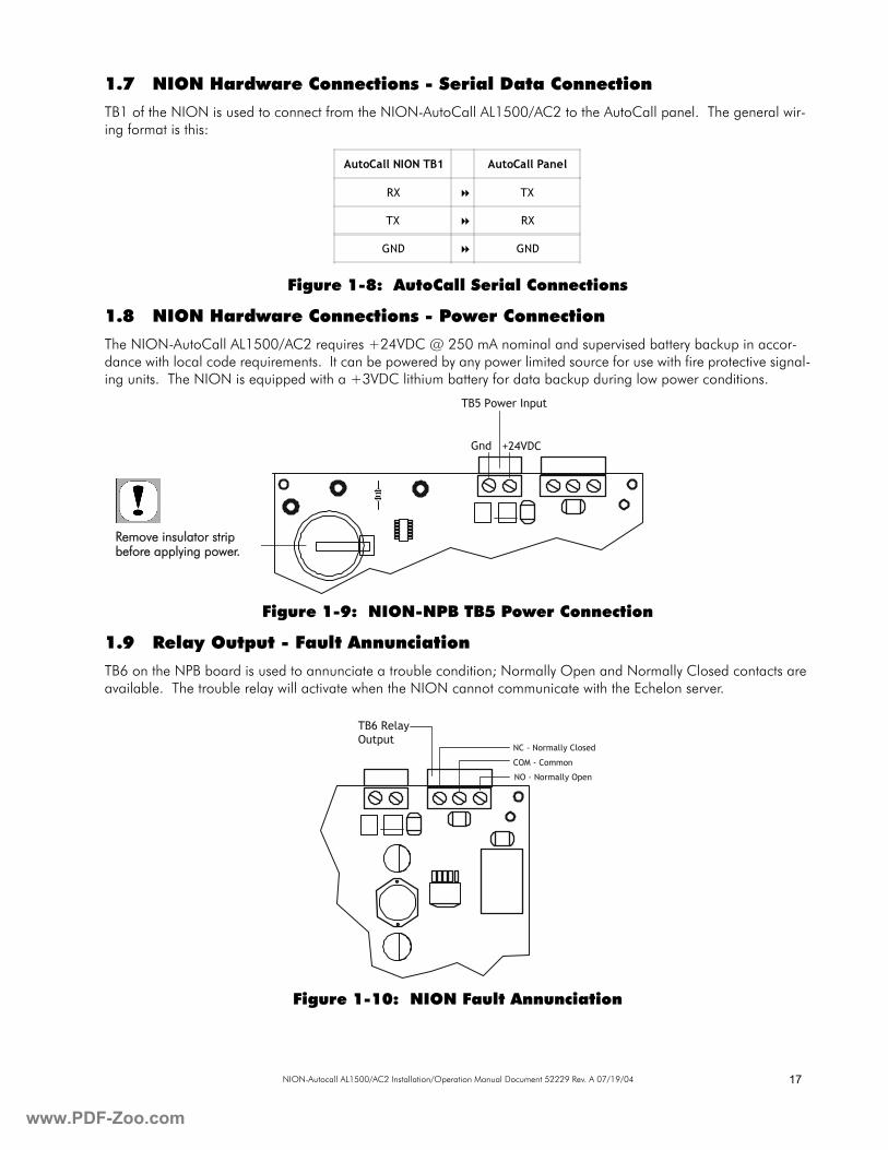
1.7 NION Hardware Connections - Serial Data Connection
TB1 of the NION is used to connect from the NION-AutoCall AL1500/AC2 to the AutoCall panel. The general wir-ing format is this:
Figure 1-8: AutoCall Serial Connections
1.8 NION Hardware Connections - Power Connection
The NION-AutoCall AL1500/AC2 requires +24VDC @ 250 mA nominal and supervised battery backup in accor-dance with local code requirements. It can be powered by any power limited source for use with fire protective signal-ing units. The NION is equipped with a +3VDC lithium battery for data backup during low power conditions.
Figure 1-9: NION-NPB TB5 Power Connection
1.9 Relay Output - Fault Annunciation
TB6 on the NPB board is used to annunciate a trouble condition; Normally Open and Normally Closed contacts are available. The trouble relay will activate when the NION cannot communicate with the Echelon server.
Figure 1-10: NION Fault Annunciation
AutoCall NION TB1 AutoCall Panel
RX TX
TX RX
GND GND
TB5 Power Input
Gnd +24VDC
Remove insulator strip before applying power.
NC - Normally Closed
TB6 RelayOutput
COM - Common
NO - Normally Open
F-Zoo.com
www
18 NION-Autocall AL1500/AC2 Installation/Operation Manual Document 52229 Rev. A 07/19/04
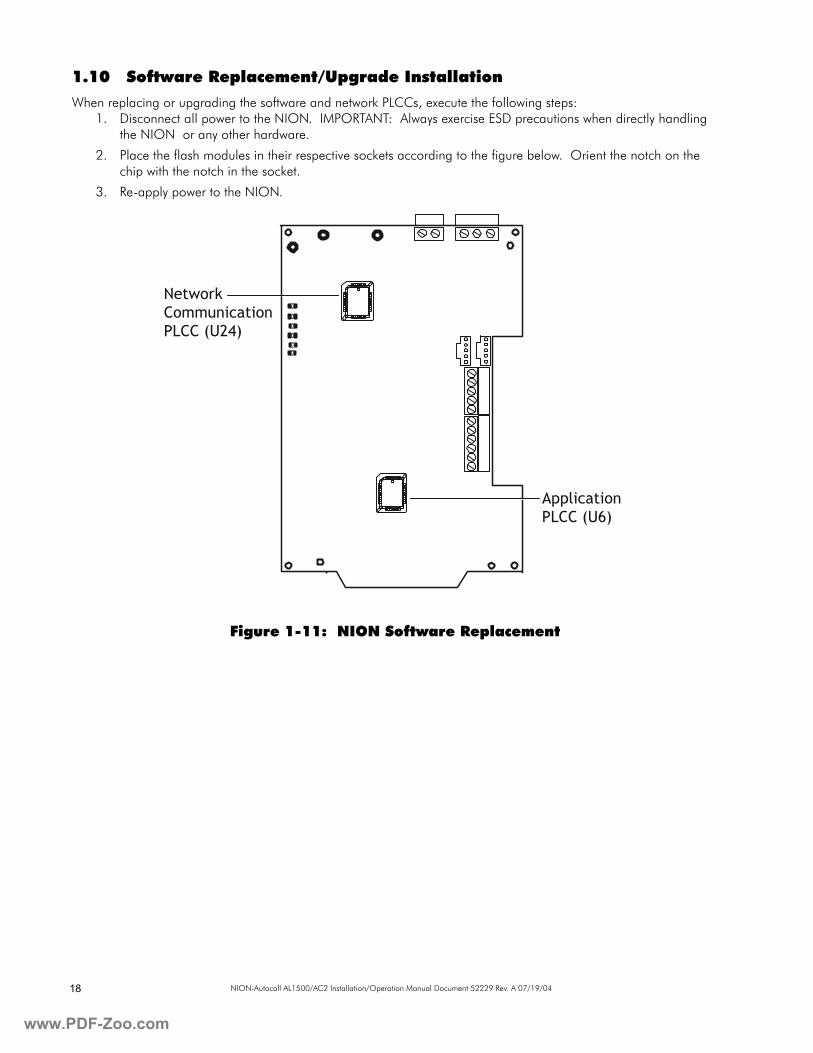
1.10 Software Replacement/Upgrade Installation
When replacing or upgrading the software and network PLCCs, execute the following steps:1. Disconnect all power to the NION. IMPORTANT: Always exercise ESD precautions when directly handling
the NION or any other hardware.
2. Place the flash modules in their respective sockets according to the figure below. Orient the notch on the chip with the notch in the socket.
3. Re-apply power to the NION.
Figure 1-11: NION Software Replacement
NetworkCommunicationPLCC (U24)
ApplicationPLCC (U6)
.PDF-Zoo.com
www.PD
19NION-Autocall AL1500/AC2 Installation/Operation Manual Document 52229 Rev. A 07/19/04
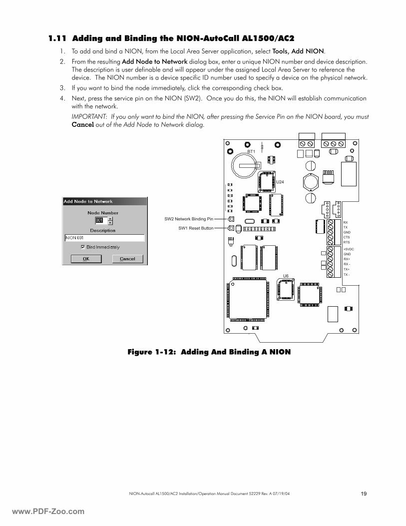
1.11 Adding and Binding the NION-AutoCall AL1500/AC2
1. To add and bind a NION, from the Local Area Server application, select Tools, Add NION.
2. From the resulting Add Node to Network dialog box, enter a unique NION number and device description. The description is user definable and will appear under the assigned Local Area Server to reference the device. The NION number is a device specific ID number used to specify a device on the physical network.
3. If you want to bind the node immediately, click the corresponding check box.
4. Next, press the service pin on the NION (SW2). Once you do this, the NION will establish communication with the network.
IMPORTANT: If you only want to bind the NION, after pressing the Service Pin on the NION board, you must Cancel out of the Add Node to Network dialog.
Figure 1-12: Adding And Binding A NION
U24
BT1
U6
SW2 Network Binding Pin
SW1 Reset ButtonRXTXGNDCTSRTS
+5VDCGNDRX+RX -TX+TX -
F-Zoo.com

www
20 NION-Autocall AL1500/AC2 Installation/Operation Manual Document 52229 Rev. A 07/19/04
.PDF-Zoo.com
www.PD
21NION-Autocall AL1500/AC2 Installation/Operation Manual Document 52229 Rev. A 07/19/04
Section 2: NION-AutoCall AL1500/AC2 Explorer2.1 AutoCall Explorer Overview
The NION-AutoCall AL1500/AC2 Explorer is a plug-in application that provides the ability to configure NION set-tings from the UniNet® 2000 workstation. The AutoCall Explorer operates much like Windows™ Explorer. It displays NION and Panel information in expandable menus the same way Windows™ Explorer displays the file system in expandable file folders.
2.2 Registering and Opening the AutoCall Explorer
To open the AutoCall Explorer application from the UniNet® 2000 workstation, it must first be properly registered with the appropriate NION type. The Workstation will automatically register the NION plug-in on the Workstation’s initial startup. If the NION needs to be manually registered, follow these steps:
• From the Workstation (UWS), go to the Workstation Configuration menu and select NION Applications. Locate the NION Type drop-down box. Scroll through the drop-down list and select the NION-AutoCall AL1500/AC2. Click the CHANGE button on the form. This will cause a dialogue box to be displayed with the names of all available configuration files. Select AutoCall.cfg and then click the OPEN button. Finally, click DONE to end the registration process.
• From the UWS, go to the Tools menu and click on Node Control Selection. Take control of the node by clicking on the node number for the NION-AutoCall AL1500/AC2, and then click on Activate Control For This Node. Click the DONE button to end the process.
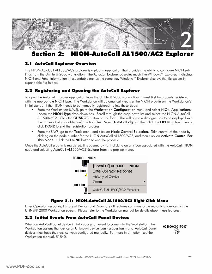
Once the AutoCall plug-in is registered, it is opened by right-clicking on any icon associated with the AutoCall NION node and selecting AutoCall AL1500/AC2 Explorer from the pop-up menu.
Figure 2-1: NION-AutoCall AL1500/AC2 Right Click MenuEnter Operator Response, History of Device, and Zoom are all features common to the majority of devices on the UniNet® 2000 Workstation screen. Please refer to the Workstation manual for details about these features.
2.3 Initial Events From AutoCall Panel Devices
When an AutoCall panel device initially causes an event to come into the Workstation, the Workstation assigns that device an Unknown device icon - a question mark. AutoCall panel devices must have their device types configured manually. For more information, see the Workstation manual, 51540.
2
F-Zoo.com
www
22 NION-Autocall AL1500/AC2 Installation/Operation Manual Document 52229 Rev. A 07/19/04
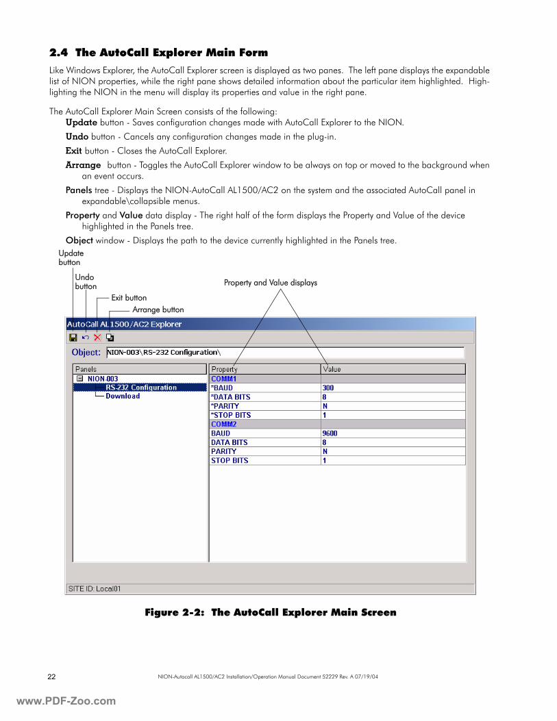
2.4 The AutoCall Explorer Main Form
Like Windows Explorer, the AutoCall Explorer screen is displayed as two panes. The left pane displays the expandable list of NION properties, while the right pane shows detailed information about the particular item highlighted. High-lighting the NION in the menu will display its properties and value in the right pane.
The AutoCall Explorer Main Screen consists of the following:Update button - Saves configuration changes made with AutoCall Explorer to the NION.
Undo button - Cancels any configuration changes made in the plug-in.
Exit button - Closes the AutoCall Explorer.
Arrange button - Toggles the AutoCall Explorer window to be always on top or moved to the background when an event occurs.
Panels tree - Displays the NION-AutoCall AL1500/AC2 on the system and the associated AutoCall panel in expandable\collapsible menus.
Property and Value data display - The right half of the form displays the Property and Value of the device highlighted in the Panels tree.
Object window - Displays the path to the device currently highlighted in the Panels tree.
Figure 2-2: The AutoCall Explorer Main Screen
Update button
Undo button
Exit buttonArrange button
Property and Value displays
.PDF-Zoo.com
www.PD
23NION-Autocall AL1500/AC2 Installation/Operation Manual Document 52229 Rev. A 07/19/04
2.5 NION Configuration through AutoCall Explorer
A user may view and configure NION settings through the AutoCall Explorer. To make changes to the NION config-uration through the explorer, the user must be logged into the UniNet® 2000 workstation with administration privi-leges.Communication SettingsThe COMM1 settings in the AutoCall Explorer must be set to match the AutoCall panel. These settings are displayed in AutoCall Explorer by selecting NION Configuration from the panels tree.
NOTE: Fields marked with an asterisk are editable.
IMPORTANT: The AutoCall NION provides only monitoring functions for devices connected to an AutoCall panel. Device icon creation is done through the Workstation application. See the Workstation manual for details concerning device icon creation.
F-Zoo.com

www
24 NION-Autocall AL1500/AC2 Installation/Operation Manual Document 52229 Rev. A 07/19/04
.PDF-Zoo.com
www.PD
25NION-Autocall AL1500/AC2 Installation/Operation Manual Document 52229 Rev. A 07/19/04
AAutoCall Explorer 21
Arrange 22Configuring NION Settings 23Exit 22Undo 22Update 22
AutoCall Explorer Main Form 22CConfiguring NION Settings 23DDFXC Transceivers 16EEnclosures 12FFault Annunciation 17FOXC Transceivers 16FTXC Transceivers 15LLEDs 11MMounting 9NNION Enclosure Installation 12NION Hardware Connections 13
SMX Network Connection 14NION PC Board Layout 10NION-AutoCall
Board Layout 10Connectors 11LEDs 11Required Equipment 9
NION-AutoCall AL1500/AC2Description 9
NION-AutoCall AL1500/AC2 Communication Set-tings 23NION-AutoCall AL1500/AC2 Explorer 21NION-AutoCall AL1500/AC2 Hardware 9NION-AutoCall AL1500/AC2 Power Connections 17NION-AutoCall AL1500/AC2 Right Click Menu 21NION-AutoCall AL1500/AC2 Serial Connections 17NION-AutoCall Hardware 9NION-NPB Board 9NION-NPB Board Layout 10NION-NPB Diagnostic LEDs 11NION-NPB LEDs 11NISCAB-1 12
NISCAB-1 Installation 12PPower Connections 17RRelated Documentation 8Relay Output 17Right Click Menu 21SSite Requirements 9Software Replacement 18Style 7 - S7FTXC Transceivers 15TTransceivers 14
Index
F-Zoo.com
www
26 NION-Autocall AL1500/AC2 Installation/Operation Manual Document 52229 Rev. A 07/19/04
Limited Warranty
NOTIFIER® warrants its products to be free from defects in materialsand workmanship for eighteen (18) months from the date ofmanufacture, under normal use and service. Products are datestamped at time of manufacture. The sole and exclusive obligation ofNOTIFIER® is to repair or replace, at its option, free of charge for partsand labor, any part which is defective in materials or workmanship undernormal use and service. For products not under NOTIFIER®manufacturing date-stamp control, the warranty is eighteen (18) monthsfrom date of original purchase by NOTIFIER®’s distributor unless theinstallation instructions or catalog sets forth a shorter period, in whichcase the shorter period shall apply. This warranty is void if the productis altered, repaired or serviced by anyone other than NOTIFIER® or itsauthorized distributors or if there is a failure to maintain the productsand systems in which they operate in a proper and workable manner. Incase of defect, secure a Return Material Authorization form from ourcustomer service department. Return product, transportation prepaid,to NOTIFIER®, 12 Clintonville Road, Northford, Connecticut 06472-1653.
This writing constitutes the only warranty made by NOTIFIER® withrespect to its products. NOTIFIER® does not represent that its productswill prevent any loss by fire or otherwise, or that its products will in allcases provide the protection for which they are installed or intended.Buyer acknowledges that NOTIFIER® is not an insurer and assumes norisk for loss or damages or the cost of any inconvenience,transportation, damage, misuse, abuse, accident or similar incident.
NOTIFIER® GIVES NO WARRANTY, EXPRESSED OR IMPLIED, OFMERCHANTABILITY, FITNESS FOR ANY PARTICULAR PURPOSE,OR OTHERWISE WHICH EXTEND BEYOND THE DESCRIPTION ONTHE FACE HEREOF. UNDER NO CIRCUMSTANCES SHALLNOTIFIER® BE LIABLE FOR ANY LOSS OF OR DAMAGE TOPROPERTY, DIRECT, INCIDENTAL OR CONSEQUENTIAL, ARISINGOUT OF THE USE OF, OR INABILITY TO USE NOTIFIER®PRODUCTS. FURTHERMORE, NOTIFIER® SHALL NOT BE LIABLEFOR ANY PERSONAL INJURY OR DEATH WHICH MAY ARISE INTHE COURSE OF, OR AS A RESULT OF, PERSONAL,COMMERCIAL OR INDUSTRIAL USE OF ITS PRODUCTS.
This warranty replaces all previous warranties and is the only warrantymade by NOTIFIER®. No increase or alteration, written or verbal, of theobligation of this warranty is authorized.
"NOTIFIER" is a registered trademark.
.PDF-Zoo.com

www.PD
27NION-Autocall AL1500/AC2 Installation/Operation Manual Document 52229 Rev. A 07/19/04
World Headquarters12 Clintonville Road
Northford, CT 06472-1653 USA203-484-7161
fax 203-484-7118
www.notifier.com
NOTIFIER is a Honeywell company.
F-Zoo.com


![Hb Ac2 Parallel en[1]](https://img.pdfslide.us/doc/110x75/55cf9ddb550346d033af8df2/hb-ac2-parallel-en1.jpg)