Embed Size (px)
Citation preview
1
archived as http://www.stealthskater.com/Documents/Tesla_02.pdf
more on Tesla is at http://www.stealthskater.com/Science.htm#Tesla
Frequently "here today but gone tomorrow", the following was archived from
http://www.rexresearch.com/teslamos/tmosc.htm on January 27, 2005 . This is NOT an
attempt to divert readers from the aforementioned website. Indeed, the reader should only
read this back-up copy if it cannot be found at the original author's site.
Nikola Tesla: Mechanical Oscillator
L. Anderson: Tesla's Teleforce & Tele-Geodynamics Proposals
D. Pond & W. Baumgartner: Nikola Tesla's Earthquake Machine
J. O'Neill: Prodigal Genius: The Life and Times of Nicola Tesla
M. Cheney: Tesla: Man Out of Time
Miscellanies
N. Tesla: US Patent # 514,169 ~ Reciprocating Engine
N. Tesla: US Patent # 517,900 ~ Steam Engine
2
Nikola Tesla's Teleforce & Telegeodynamics Proposals Leland Anderson
ISBN: 0-9636012-8-8
2 important papers -- hidden for more than 60 years -- are presented for the first time. The principles
behind teleforce (the particle-beam weapon) and telegeodynamics (the mechanical earth-resonance
concept for seismic exploration) are fully addressed. In addition to copies of the original documents
typed on Tesla's official stationery, this work also includes 2 "Reader's Aid" sections that guide the
reader through the more technical aspects of each paper. The papers are followed by "Commentary"
sections which provide historical background and functional explanations of the 2 devices. Significant
newspaper articles and headline accounts are provided to document the first mention of these proposals.
A large "Appendix" provides a wealth of related material and background information, followed by a
"Bibliography" section and "Index".
This book contains the original texts of 2 unique proposals that Nikola Tesla offered up during his
later years. In both cases, the technologies described trace their roots back to an earlier and
tremendously productive decade in Tesla's life beginning in the early 1890s. At the time of the
proposals unveiling, "teleforce" (the particle beam concept) and "telegeodynamics" (the mechanical
earth-resonance concept) received significant press coverage.
On the occasion of his annual birthday celebration interview by the press on July 10, 1935 in his
suite at the Hotel New Yorker, Tesla announced a method of transmitting mechanical energy
accurately with minimal loss over any terrestrial distance, including a related new means of
communication and a method --he claimed -- which would facilitate the unerring location of
underground mineral deposits. At that time, he recalled the earth-trembling "quake" that brought police
and ambulances rushing to the scene of his Houston Street laboratory while an experiment was in
progress with one of his mechanical oscillators. [StealthSkater note: makes one wonder if all the
recent earthquakes in the Middle East and India/Pakistan were really caused by Nature.]
Excerpt follows …
3
Reactive Forces Obtainable by Tesla's Isochronous Oscillators
These are generated by Tele-Geo-Dynamic transmitters which are reciprocating engines of extreme
simplicity adapted to impress isochronous vibrations upon the Earth, thereby causing the propagation of
corresponding rhythmical disturbances through the same which are, essentially, sound waves like those
conveyed through the air and ether. ... With a machine of this kind, it will be practicable -- in the
differentiation of densities and aggregate states of subterranean strata and tracing their outlines on the
Earth's surface -- to reach a precision approximating that which is secured in the investigation of the
internal structure of bodies by penetrative rays. For just as the vacuum tube projects Roentgen shadows
on a fluorescent screen, so the transmitter produces on the Earth's surface shadows which can be
detected by acoustic devices or rendered visible by optical instruments. The receiver can be made so
sensitive that prospecting may be accomplished while riding in a car and without limit of distance from
the transmitter.
Table of Contents Introduction
Nikola Tesla's Teleforce Proposal
Reader's Aid
New Art of Projecting Concentrated Non-Dispersive Energy Through Natural Media. By Nikola
Tesla
Commentary
New York Times, September 22, 1940, "'Death Ray' for Planes"
Nikola Tesla's Telegeodynamics Proposal
Reader's Aid
Relative Merits of the Lucas Method of Prospecting by Detonations of Explosive Compounds
and of The Tesla Method of Prospecting by Isochronous Oscillations Theoretically
Considered. By Nikola Tesla
Tesla correspondence from George Scherff, June 17, 1937
Commentary
New York Times, July 11, 1935, "Tesla, 79, Promises to Transmit Force"
Appendix
Teleforce Proposal
Possibilities of Electrostatic Generators. By Nikola Tesla
Tesla Correspondence to J. P. Morgan, Jr., November 29, 1934
Telegeodynamics Proposal
Tesla correspondence from George Scherff, April 19, 1918
Address Before The New York Electrical Society, "Mechanical and Electrical Oscillators" by
Nikola Tesla
Electric Generator ~ U.S. Patent No. 511,916
Reciprocating Engine ~ U.S. Patent No. 514,169
Steam Engine ~ U.S. Patent No. 517,900
Mechanical Therapy by Nikola Tesla
Detroit Free Press, Jan. 18, 1896, "Tesla's Health Giver"
Bibliography
Teleforce
Telegeodynamics
Afterword
Bibliography
4
Nikola Tesla's Earthquake Machine Dale Pond & Walter Baumgartner
(Available from: www.tfcbooks.com )
Much of the material presented in this book is related to the construction of a class of machine
invented by Tesla and known as the reciprocating Mechanical Oscillator. Serious students of Tesla's
work may recognize this machine as the basis of his system for producing electrical vibrations of a very
constant period.
In 1898, another variation was used to create a small earthquake in the neighborhood surrounding his
Houston Street lab. Tesla called this method of transmitting mechanical energy "telegeodynamics".
Included are mechanical drawings that will guide you through the construction of a working model of
the Tele-Geo-Dynamic Oscillator, plus a comprehensive description of the machine in Tesla's own
words."
5
Excerpt from:
Prodigal Genius: The Life and Times of Nicola Tesla John O'Neill
Tele-Geo-Dynamics
Tele-Geo-Dynamics is the transmission of sonic or acoustic vibrations, which can be produced
with comparatively simple apparatus. There is, of course, much sonic equipment available now for
different applications. But this has little or nothing to do with Nikola Tesla's oscillator-generator. What
Tesla proposed represents a new technology in sonic transmission even today. [StealthSkater note:
could this in any way be connected to John Keely's vibrational theories?]
In Tesla's oscillator-generator, a resonance effect can be observed. Since resonance seems to be an
ever-increasing effect with this oscillator-generator, it can be deduced that there must be a great source
of energy available through it.
Why can a resonance be created in the oscillator-generator when it cannot in an ordinary
reciprocating engine? With the oscillator-generator, all governing mechanisms are eliminated. On the
other hand, consider the car engine. Starting with the cylinder, a reciprocating motion is converted into
rotary motion by a means of shafts, cranks, gears, drivetrains, transmissions, etc.
These parts all consume work by friction. But the greatest loss occurs in the change from
reciprocating to rotary motion. At each point every varying inclination of the crank and pistons work at
a disadvantage and result in loss of efficiency.
In Tesla's oscillator-generator, the piston is entirely free to move as the medium impels it without
having to encounter and overcome the inertia of a moving system. In this respect, the 2 types of engines
differ radically and essentially.
This type of engine -- under the influence of an applied force such as the tension of compressed air,
steam, or other gases under pressure -- yields an oscillation of a constant period.
The objective of the Tesla oscillator-generator is to provide a mechanism capable of converting the
energy of compressed gas or steam into mechanical power. Since the oscillator-generator is denuded of
all governing devices, friction is almost non-existent. In other words, the piston floats freely in air and
is capable of converting all pressure into mechanical energy.
Our objective in building the engine is to provide an oscillator which -- under the influence of an
applied force (such as the elastic tension of a gas under pressure) -- will yield an oscillating movement
which (within very wide limits) will be of constant period irrespective of variation of load, frictional
losses, and other factors which in ordinary engines change in the rate of reciprocating.
It is a well-known principle that if a spring possessing a sensible inertia is brought under tension
(i.e., being stretched) and then freed, it will perform vibrations which are "isochronous". As far as the
period in general is concerned, it will depend on the rigidity of the spring and its own inertia or that of
the system of which it may form an immediate part. This is known as Simple Harmonic Motion.
This simple harmonic motion in the form of isochronous sound vibrations can be impressed upon the
Earth, causing the propagation of corresponding rhythmical disturbances through the same which pass

6
through its remotest boundaries without attenuation so that the transmission is affected with an
efficiency of 100 percent.
7
Excerpt from:
Tesla: Man Out of Time Margaret Cheney
He attached an oscillator no larger than an alarm clock to a steel link 2' long and 2" thick.
"For a long time nothing happened. But at last, the great steel link began to tremble, increased its
trembling until it dilated and contracted like a beating heart, and finally broke. Sledgehammers could
not have done it", he told a reporter. "Crowbars could not have done it. But a fusillade of taps -- not
one of which would have harmed a baby -- did it!"
Pleased with this beginning, he put the little oscillator in his coat pocket. Finding a half-built steel
building in the Wall Street district 10 stories high with nothing up but the steelwork, he clamped the
oscillator to one of the beams.
"In a few minutes, I could feel the beam trembling. Gradually, the trembling increased in intensity
and extended throughout the whole great mass of steel. Finally, the structure began to creak and weave,
and the steelworkers came to the ground panic-stricken believing that there had been an earthquake.
Before anything serious happened, I took off the oscillator, put it in my pocket and went away. But if I
had kept on 10 minutes more, I could have laid that building flat in the street. And with the same
oscillator, I could drop Brooklyn Bridge in less than an hour."
8
Miscellanies
Sparling, Earl: N. Y. World-Telegram (July 11, 1935), "Nikola Tesla at 79 Uses Earth to Transmit
Signals; Expects to have $100,000,000 Within 2 Years" :
Here Tesla tells the story of the earthquake generated by the mechanical oscillator in his NYC
laboratory in 1898, which brought the police there to stop him. They entered the lab just in time to see
Tesla swing a sledgehammer to smash the tiny device, which was mounted on a girder.
Nikola Tesla revealed that an earthquake (which drew police and ambulances to the region of his
laboratory at 48 E. Houston St., New York in 1898) was the result of a little machine he was
experimenting with at the time which "you could put in your overcoat pocket."
The bewildered newspapermen pounced upon this as at least one thing they could understand. And
the "Father of Modern Electricity" told what had happened as follows:
"I was experimenting with vibrations. I had one of my machines going and I wanted to see if I could
get it in tune with the vibration of the building. I put it up notch-after-notch. There was a peculiar
cracking sound.
"I asked my assistants where did the sound come from. They did not know. I put the machine up a
few more notches. There was a louder cracking sound. I knew that I was approaching the vibration of
the steel building. I pushed the machine a little higher.
"Suddenly all the heavy machinery in the place was flying around. I grabbed a hammer and broke
the machine. The building would have been about our ears in another few minutes. Outside in the
street, there was pandemonium.
"The police and ambulances arrived. I told my assistants to say nothing. We told the police it must
have been an earthquake. That's all they ever knew about it."
At this point, some shrewd reporter asked Dr. Tesla what he would need to destroy the Empire State
Building. The doctor replied: "Vibration will do anything. It would only be necessary to step up the
vibrations of the machine to fit the natural vibration of the building, and the building would come
crashing down. That's why soldiers break step crossing a bridge."
In another interview, he boasted that "With this principle, one could split the Earth in half like
an apple".
Century Magazine, p. 921, Figure 2 (April 1895). In 1893, Tesla constructed a preferred embodiment of
the mechanical oscillator which he described as a "double compound mechanical and electrical
oscillator for generating current of perfect, constant, dynamo frequency of 10 horsepower."
Allan L. Benson: World Today (Feb. 1912); "Nikola Tesla, Dreamer". An illustration for the article
shows an artist's conception of the Planet splitting in two. The caption reads: "Tesla claims that
in a few weeks he could set the Earth's crust into such a state of vibration that it would rise-and-
fall hundreds-of-feet and practically destroy Civilization. A continuation of this process would,
he says, "eventually split the Earth in two."
9
New York Sun (July 10, 1935); "New Apparatus Transmits Energy. Tesla Announces Method of
Remote Control".
N. Y. American (July 11, 1935), Section 2; "Tesla's Controlled Earth Quakes Power Through the Earth,
A Startling Discovery".
New York Herald Tribune (July 11, 1935), pp. 1, 8; "Tesla, at 79, Discovers New Message Wave - At
Birthday Luncheon He Announces Machine for 1-Way Communication"
New York Sun (July 11, 1935); "Nikola Tesla Describes New Invention - Art of Tele-Geodynamics"
New York Times (July 11, 1935), p. 23, col. 8; "Tesla, 79, Promises to Transmit Force - Transmission of
Energy Over World".
10
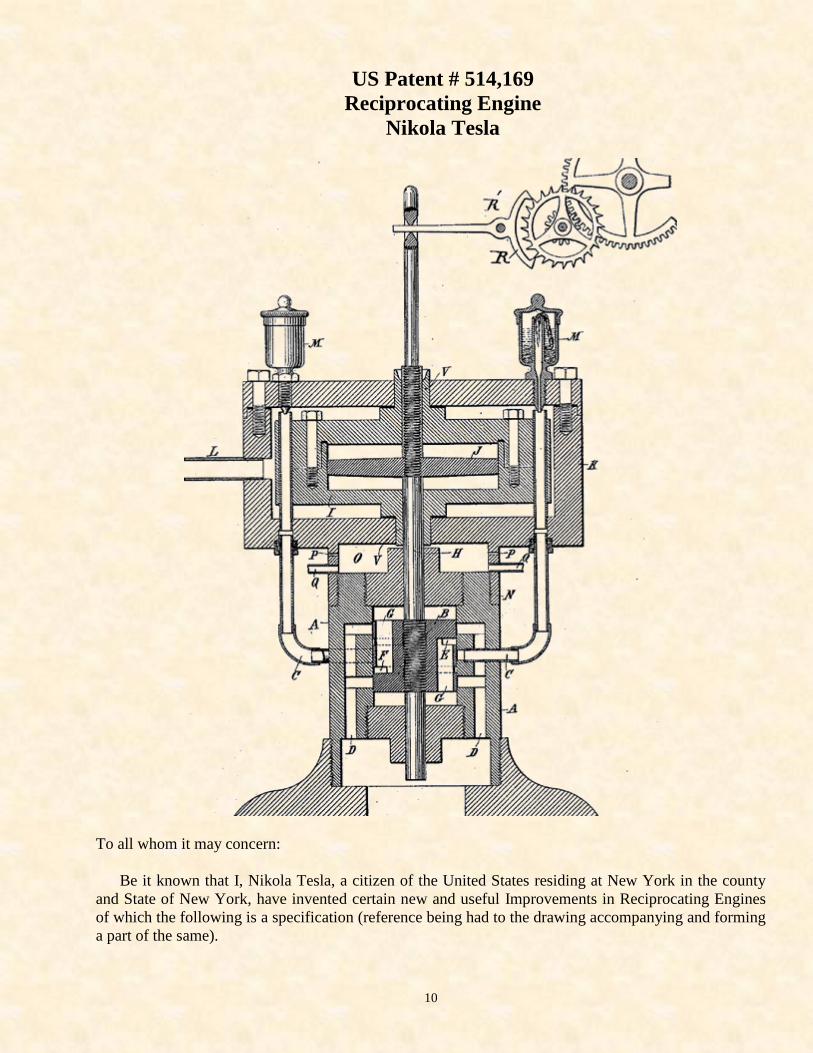
US Patent # 514,169
Reciprocating Engine
Nikola Tesla
To all whom it may concern:
Be it known that I, Nikola Tesla, a citizen of the United States residing at New York in the county
and State of New York, have invented certain new and useful Improvements in Reciprocating Engines
of which the following is a specification (reference being had to the drawing accompanying and forming
a part of the same).
11
In the invention which forms the subject of my present application, my object has been primarily to
provide an engine, which under the influence of an applied force (such as the elastic tension of steam or
gas under pressure) will yield an oscillatory movement which -- within very wide limits -- will be of
constant period irrespective of variations of load, frictional losses, and other factors which in all
ordinary engines produce change in the rate of reciprocation.
The further objects of the invention are to provide a mechanism capable of converting the energy of
steam or gas under pressure into mechanical power more economically than the forms of engine
heretofore used, chiefly by overcoming the losses which result in these by the combination with rotating
parts possessing great inertia of a reciprocating system which also is better adapted for use at higher
temperatures and pressures, and which is capable of useful and practical application to general industrial
purposes, particularly in small units.
The invention is based upon certain well-known mechanical principles, a statement of which will
assist in a better understanding of the nature and purposes of the objects sought and results obtained.
Heretofore where the pressure of steam or any gas has been utilized and applied for the production of
mechanical motion, it has been customary to connect with the reciprocating or moving parts of the
engine a fly-wheel or some rotary system equivalent in its effect and possessing relatively great
mechanical inertia, upon which dependence was mainly placed for the maintenance of constant speed.
While securing in a measure this object, this renders impossible the attainment of the result at which I
have arrived, and is attended by disadvantages which by my invention are entirely obviated. On the
other hand, in certain cases where reciprocating engines or tools have been used without a rotating
system of great inertia, no attempt -- so far as I know -- has been made to secure conditions which would
necessarily yield such results as I have reached.
It is a well-known principle that if a spring possessing a sensible inertia be brought under tension (as
by being stretched) and then freed, it will perform vibrations which are isochronous and (as to period) in
the main dependent upon the rigidity of the spring and its own inertia or that of the system of which it
may form an immediate part. This is known to be true in all cases where the force which tends to bring
the spring or movable system into a given position is proportionate to the displacement.
In carrying out my invention and for securing the objects in general terms stated above, I employ the
energy of steam or gas under pressure -- acting through proper mechanism -- to maintain in oscillation a
piston. And taking advantage of the law above stated, I connect with said piston (or cause to act upon it,
a spring) under such conditions as to automatically regulate the period of the vibration so that the
alternate impulses of the power impelled piston and the natural vibrations of the spring shall always
correspond in direction and coincide in time.
While in the practice of the invention I may employ any kind of spring or elastic body of which the
law or principle of operation above defined holds true, I prefer to use an air spring, or generally speaking
a confined body or cushion of elastic fluid as the mechanical difficulties in the use of metallic springs
are serious, owing mainly to the tendency to break. Moreover, instead of permitting the piston to
impinge directly upon such cushions within its own cylinder, I prefer -- in order to avoid the influence of
the varying pressure of the steam or gas that acts upon the piston and which might disturb the relations
necessary for the maintenance of isochronous vibration, and also to better utilize the heat generated by
the compression -- to employ an independent plunder connected with the main piston, and a chamber or
cylinder therefore (containing air which is normally at the same pressure as the external atmosphere), for
thus a spring of practically constant rigidity is obtained, but the air or gas within the cylinder may be
maintained at any pressure.
12
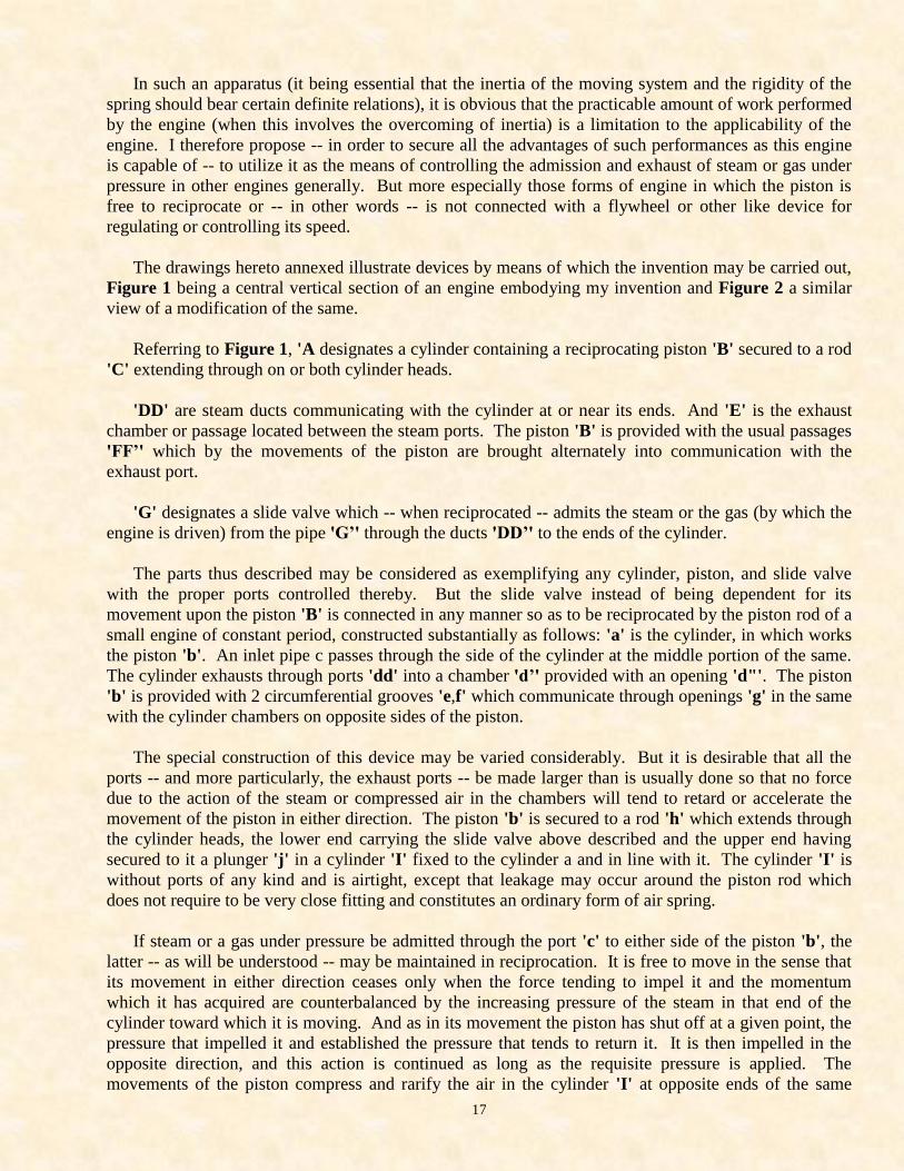
In order to describe the best manner of which I am aware in which the invention is or may be carried
into effect, I refer now to the accompanying drawing which represents in central cross-section an engine
embodying my improvements.
'A' is the main cylinder in which works a piston 'B'. Inlet ports 'CC' pass through the sides of the
cylinder, opening at the middle portion thereof and on opposite sides. Exhaust ports 'DD' extend
through the wall of the cylinder and are formed with branches that open into the interior of the cylinder
on each side of the inlet ports and on opposite sides of the cylinder.
The piston 'B' is formed with 2 circumferential grooves 'EF', which communicate through openings
'G' in the piston with the cylinder on opposite sides of said piston respectively.
I do not consider as of special importance the particular construction and arrangement of the
cylinder, the piston, and the ports for controlling it except that it is desirable that all the ports -- and
more especially the exhaust ports -- should be made very much larger than is usually the case so that no
force due to the action of the steam or compressed air will tend to retard of affect the return of the piston
in either direction.
The piston 'B' is secured to a piston rod 'H', which works in suitable stuffing boxes in the heads of
the cylinder 'A'. This rod is prolonged on one side and extends through bearings 'V' in a cylinder 'I'
suitably mounted or supported in line with the first, and within which is a disk or plunger 'J' carried by
the rod 'H'.
The cylinder 'I' is without ports of any kind and is air-tight except as a small leakage may occur
through the bearings 'V', which experience has shown need not be fitted with any very considerable
accuracy. The cylinder 'I' is surrounded by a jacket 'K' which leaves an open space or chamber around
it. The bearings 'V' in the cylinder 'I' extend through the jacket 'K' which leaves an open space or
chamber around it. The bearings 'V' in the cylinder 'I' extend through the jacket 'K' to the outside air,
and the chamber between the cylinder and jacket is made steam or airtight as by suitable packing. The
main supply line 'L' for steam or compressed air leads into this chamber. And the 2 pipes that lead to
the cylinder 'A' run from the said chamber, oil cups 'M' being conveniently arranged to deliver oil into
the said pipes for lubricating the piston.
In the particular form of engine shown, the jacket 'K' which contains the cylinder 'I' is provided
with a flange 'N' by which it is screwed to the end of cylinder 'A'. A small channel 'O' is thus formed
which has air vents 'P' in its sides and drip pipes 'Q' leading out from it through which the oil which
collects in it is carried off.
To explain now the operation of the device above described. In the position of the parts shown or
when the piston is at the middle point of its stroke, the plunger 'J' is at the center of the cylinder 'I' and
the air on both sides of the same is at the normal pressure of the outside atmosphere. If a source of
steam or compressed air is then connected to the inlet ports 'CC' of the cylinder 'A' and a movement be
imparted to the piston as by a sudden blow, the latter is caused to reciprocate in a manner well
understood. The movement of the piston in either direction ceases when the force tending to impel it
and the momentum which it has acquired are counterbalanced by the increasing pressure of the steam or
compressed air in that end of the cylinder toward which it is moving and as in its movement the piston
has shut off at a given point, the pressure that impelled it and established the pressure that tends to return
it. It is then impelled in the opposite direction, and this action is continued as long as the requisite
pressure is applied. The movements of the piston compress and rarify the air in the cylinder 'I' at
opposite ends of the same alternately. A forward stroke compresses the air ahead of the plunger 'J' and
tends to drive it forward. This action of the plunger upon the air contained in the opposite ends of the
13
cylinder is exactly the same in principle as though a piston rod were connected to the middle point of a
coiled spring, the ends of which are connected to fixed supports.
Consequently the 2 chambers may be considered as a single spring. The compressions of the air in
the cylinder 'I' and the consequent loss of energy (due mainly to the imperfect elasticity of the air) give
rise to a very considerable amount of heat. I utilize this heat by conducting the steam or compressed air
to the engine cylinder through the chamber formed by the jacket surrounding the air-spring cylinder. The
heat thus taken up and used to raise the temperature of the steam-or-air acting upon the piston is availed
of to increase the efficiency of the engine. In any given engine of this kind, the normal pressure will
produce a stroke of determined length. And this will be increased-or-diminished according to the
increase of pressure above or the reduction of pressure below the normal.
In constructing the apparatus, I allow for a variation in the length of stroke by giving to the confining
cylinder I of the air spring properly determined dimensions. The greater the pressure upon the piston,
the higher will be the degree of compression of the air-spring and the consequent counteracting force
upon the plunger. The rate or period of reciprocation of the piston, however, is no more dependent upon
the pressure applied to drive it than would be the period of oscillation of a pendulum permanently
maintained in vibration upon the force which periodically impels it -- the effect of variations in such
force being merely to produce corresponding variations in the length of stroke or amplitude of vibration
respectively.
The period is mainly determined by the rigidity of the air spring and the inertia of the moving
system. And I may therefore secure any period of oscillation within very wide limits by properly
portioning these factors as by varying the dimensions of the air chamber which is equivalent to varying
the rigidity of the spring or by adjusting the weight of the moving parts. These conditions are all readily
determinable. And an engine constructed as herein described my be made to follow the principle of
operation above-stated and maintain a perfectly uniform period through very much wider limits of
pressure than in ordinary use it is ever likely to be subjected to. And it may be successfully used as a
prime-mover wherever a constant rate of oscillation or speed is required, provided the limits -- within
which the forces tending to bring the moving system to a given position are proportionate to the
displacements -- are not materially exceeded.
The pressure of the air confined in the cylinder when the plunger 'J' is in its central position will
always be practically that of the surrounding atmosphere. For while the cylinder is so constructed as not
to permit such sudden escape of air as to sensibly impair or modify the action of the air spring, there will
be a slow leakage of air into or out of it around the piston rod according to the pressure therein so that
the pressure of the air on opposite sides of the plunger will always tend to remain at that of the outside
atmosphere.
As an instance of the uses to which this engine may be applied, I have shown its piston rod
connected with a pawl 'R', the oscillation of which drives a train of wheels. These may constitute the
train of a clock or of any other mechanism. The pawl 'R' is pivoted at 'R’' and its bifurcated end
engages with the teeth of the ratchet wheel alternately on opposite sides of the same -- one end of the
pawl at each half oscillation acting to propel the wheel forward through the space of one tooth when it is
engaged and locked by the other end on the last half of the oscillation, which brings the first end of the
oscillation into position to engage with another tooth.
Another application of the invention is to move a conductor in a magnetic field for generating
electric currents. In these and similar uses, it is obvious that the characteristics of the engine render it
especially adapted for use in small sizes or units.

14
Having now described my invention, what I claim is … [Claims not included here ]
15
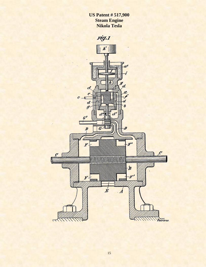
US Patent # 517,900
Steam Engine
Nikola Tesla
16
To all whom it may concern:
Be it known that I, Nikola Tesla, a citizen of the United States residing at New York in the county
and State of New York, have invented certain new and useful Improvements in Steam Engines, of which
the following is a specification (reference being had to the drawing accompanying and forming a part of
the same).
Heretofore, engines -- operated by the application of a force such as the elastic tension of steam or a
gas under pressure -- have been provided with a flywheel or some rotary system equivalent in its effect
and possessing relatively great mechanical inertia, which was relied upon for maintaining a uniform
speed. I have produced, however, an engine which -- without such appurtenances -- produces under
very wide variations of pressure, load, and other disturbing causes, an oscillating movement of constant
period and have shown and described the same in [US Patent # 514,169 ]. A description of the principle
of the construction and mode of operation of this device is necessary to an understanding of my present
invention.
When a spring which possess a sensible inertia is brought under tension (as by being stretched and
then freed), it will perform vibrations which are isochronous and -- as to period -- in the main dependent
upon the rigidity of the spring, and its own inertia or that of the system of which it may form an
immediate part. This is known to be true in all cases where the force which tends to bring the spring or
movable system into a given position is proportionate to the displacement. In utilizing this principle for
the purpose of producing reciprocating movement of a constant period, I employ the energy of steam or
gas under pressure (acting through proper mechanism) to maintain in oscillation a piston. And connect
with it or cause to act upon such piston a spring (preferably an air spring) under such conditions as to
automatically regulate the period of the vibration, so that the alternate impulses of the power impelled
piston and the natural vibrations of the spring shall always correspond in direction and coincide in time.
17
In such an apparatus (it being essential that the inertia of the moving system and the rigidity of the
spring should bear certain definite relations), it is obvious that the practicable amount of work performed
by the engine (when this involves the overcoming of inertia) is a limitation to the applicability of the
engine. I therefore propose -- in order to secure all the advantages of such performances as this engine
is capable of -- to utilize it as the means of controlling the admission and exhaust of steam or gas under
pressure in other engines generally. But more especially those forms of engine in which the piston is
free to reciprocate or -- in other words -- is not connected with a flywheel or other like device for
regulating or controlling its speed.
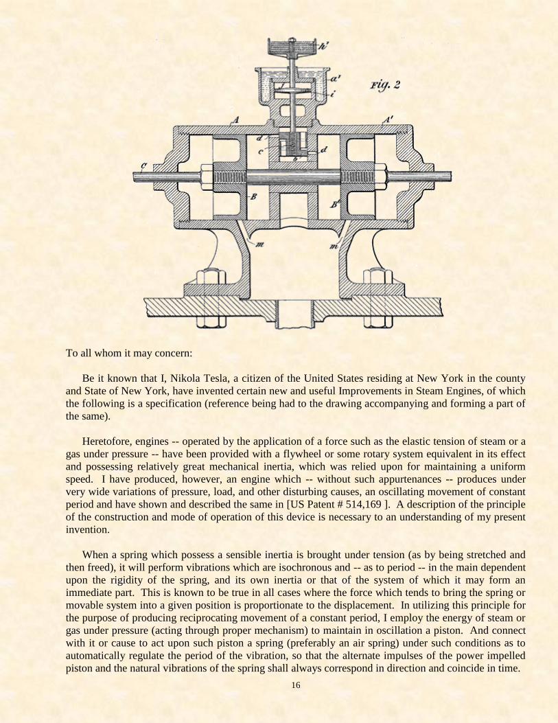
The drawings hereto annexed illustrate devices by means of which the invention may be carried out,
Figure 1 being a central vertical section of an engine embodying my invention and Figure 2 a similar
view of a modification of the same.
Referring to Figure 1, 'A designates a cylinder containing a reciprocating piston 'B' secured to a rod
'C' extending through on or both cylinder heads.
'DD' are steam ducts communicating with the cylinder at or near its ends. And 'E' is the exhaust
chamber or passage located between the steam ports. The piston 'B' is provided with the usual passages
'FF’' which by the movements of the piston are brought alternately into communication with the
exhaust port.
'G' designates a slide valve which -- when reciprocated -- admits the steam or the gas (by which the
engine is driven) from the pipe 'G’' through the ducts 'DD’' to the ends of the cylinder.
The parts thus described may be considered as exemplifying any cylinder, piston, and slide valve
with the proper ports controlled thereby. But the slide valve instead of being dependent for its
movement upon the piston 'B' is connected in any manner so as to be reciprocated by the piston rod of a
small engine of constant period, constructed substantially as follows: 'a' is the cylinder, in which works
the piston 'b'. An inlet pipe c passes through the side of the cylinder at the middle portion of the same.
The cylinder exhausts through ports 'dd' into a chamber 'd’' provided with an opening 'd"'. The piston
'b' is provided with 2 circumferential grooves 'e,f' which communicate through openings 'g' in the same
with the cylinder chambers on opposite sides of the piston.
The special construction of this device may be varied considerably. But it is desirable that all the
ports -- and more particularly, the exhaust ports -- be made larger than is usually done so that no force
due to the action of the steam or compressed air in the chambers will tend to retard or accelerate the
movement of the piston in either direction. The piston 'b' is secured to a rod 'h' which extends through
the cylinder heads, the lower end carrying the slide valve above described and the upper end having
secured to it a plunger 'j' in a cylinder 'I' fixed to the cylinder a and in line with it. The cylinder 'I' is
without ports of any kind and is airtight, except that leakage may occur around the piston rod which
does not require to be very close fitting and constitutes an ordinary form of air spring.
If steam or a gas under pressure be admitted through the port 'c' to either side of the piston 'b', the
latter -- as will be understood -- may be maintained in reciprocation. It is free to move in the sense that
its movement in either direction ceases only when the force tending to impel it and the momentum
which it has acquired are counterbalanced by the increasing pressure of the steam in that end of the
cylinder toward which it is moving. And as in its movement the piston has shut off at a given point, the
pressure that impelled it and established the pressure that tends to return it. It is then impelled in the
opposite direction, and this action is continued as long as the requisite pressure is applied. The
movements of the piston compress and rarify the air in the cylinder 'I' at opposite ends of the same
18
alternately, and this results in the heating of the cylinder. But since a variation of the temperature of the
air in the chamber would affect the rigidity of the air spring, I maintain the temperature uniform as by
surrounding the cylinder I with a jacket 'a’' which is open to the air and filled with water.
In such an engine as that just described, the normal pressure will produce a stroke of determined
length which may be increased-or-diminished according to the increase of pressure above or the
reduction of pressure below the normal. And due allowance is made in constructing the engine for a
variation in the length of stroke or amplitude of vibration respectively. The period is mainly determined
by the rigidity of the air spring and the inertia of the moving system. I may therefore secure any period
of oscillation within very wide limits by properly adjusting these factors, as by varying the dimensions
of the air chamber which may be equivalent to varying the rigidity of the spring or by adjusting the
weight of the moving parts. This latter is readily accomplished by making provision for the attachment
to the piston rod of one-or-more weights 'h’'. Since the only work which the small engine has to
perform is the reciprocation of the valve attached to the piston rod, its load is substantially uniform and
its period by reason of its construction will be constant. Whatever may be the load on the main engine,
therefore the steam is admitted to the cylinder at defined intervals. And thus any tendency to a change
of the period of vibration in the main engine is overcome.
The control of the main engine by the engine of constant period may be affected in other ways of
which Figure 2 will serve as an illustration. In this case, the piston of the controlling engine constitutes
the slide valve of the main engine so that the latter may be considered as operated by the exhaust of the
former. In the figure, I have shown 2 cylinders 'AA’' placed end-to-end with a piston 'B' and 'B’' in
each. The cylinder of the controlling engine is formed by or in the casing intermediate to the 2 main
cylinders. But in all other essential respects, the construction and mode of operation of the controlling
engine remains as described in connection with Figure 1. The exhaust ports 'dd', however, constitute
the inlet ports of the cylinders 'AA’'. And the exhaust of the latter is effected through the ports 'm,m'
which are controlled by the pistons 'B' and 'B’' respectively. The inlet port for the admission of the
steam to the controlling engine is similar to that in Figure 1 and is indicated by the dotted circle at the
center of the piston 'b'.
An engine of the kind described possess many and important advantages. A much more perfect
regulation and uniformity of action is secured, while the engine is simple and its weights for a given
capacity is very greatly reduced. The reciprocating movement of the piston may be converted into
rotary motion. Or it may be utilized and applied in any other manner desired either directly or
indirectly.
In [US Patent # 514,169], I have shown and described 2 reciprocating engines combined in such
manner that the movement or operation of one is dependent upon and controlled by the other. In the
present case, however, the controlling engine is not designed nor adapted to perform other work than the
regulation of the period of the other. And it is moreover an engine of defined character which has the
capability of an oscillating movement of constant period.
What I claim is … [Claims not included here ]

19
if on the Internet, Press <BACK> on your browser to return
to the previous page (or go to www.stealthskater.com)
else if accessing these files from the CD in a MS-Word session, simply <CLOSE>
this file's window-session; the previous window-session should still remain 'active'