Embed Size (px)
Citation preview

DCS Page 1
Innovative Production Technology
DATRON Case Study
DATRON Dynamics, Inc.
115 Emerson RoadMilford, NH 03055
Phone: 888.262.2833www.datron.com
DATRON Dynamics West 6255 Southfront RoadLivermore, CA 94551
888.262.2833DATRON_Aero_Tec_Case_Study_2017_v1
Aero-Tec Industries, based in Seminole, OK, manufactures a wide variety of internally illuminated
control panels for usage in fixed wing, rotary wing and simulator applications. A large percentage
of these are manufactured to be compatible with night vision goggles. Special lamp filtration and
paints are required for this.
In 2005, Aero-Tec President, Charles Harbert set out to find a CNC machine capable of batch
machining illuminated displays for aircraft communications gear from cast acrylic. But these were
to be no ordinary displays and to produce them to exacting specifications Aero-Tec needed to find
an extraordinary piece of equipment.
According to Harbert, “Encapsulated within the part are two sealed 5 volt lamp modules — one
provides backlighting for UHF and the other [at the top] illuminates the display that sits behind a
clear window. The lamp modules are filtered in order to be compatible with night-vision goggles
worn by military pilots ... and the lettering at the bottom is non-illuminated.” The parts shown here
include a completed part (minus the two wires that come out of the recessed terminals on the
back) and the two other parts show the innards and illustrate the complicated steps required for
manufacturing this part.
When Aero-Tec came across Datron Dynamics, Inc., (Milford, NH) on the Internet, Harbert’s hope
for superior technology was bolstered by a website that showed vanguard high-speed machining
centers ... and perhaps more importantly, a smorgasbord of integrated features that smacked of a
real turn-key solution. “In particular” said Harbert, “I was interested in how Datron’s high speed
technology and integrated vacuum table could impact our efficiency and the overall quality of our
entire product line.”
Night Flight via High Speed.
CUSTOMER: Aero-Tec Industries 11990 NS 356 (Hwy 99 North) Seminole, OK 74868 405.382.8501
Photo 3:
Black and white layers of paint are
milled away on the top wall of the
window opening.
Step 1:
Blanks milled from sheet of military-
grade cast acrylic.
Step 2:
Parts are secured with the vacuum
fixture so that all of the detailed
features that appear on the back can
be machined.
DCS Page 2
Innovative Production Technology
DATRON Case Study
DATRON Dynamics, Inc.
115 Emerson RoadMilford, NH 03055
Phone: 888.262.2833www.datron.com
DATRON Dynamics West 6255 Southfront RoadLivermore, CA 94551
888.262.2833DATRON_Aero_Tec_Case_Study_2017_v1
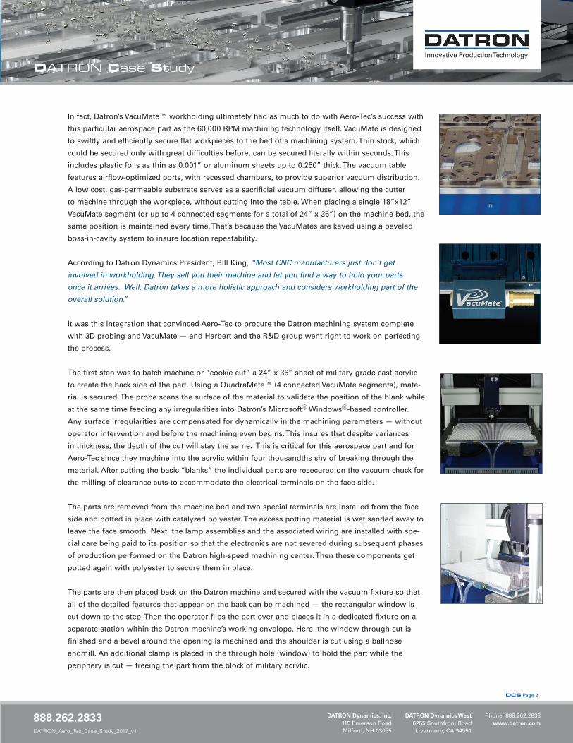
In fact, Datron’s VacuMate™ workholding ultimately had as much to do with Aero-Tec’s success with
this particular aerospace part as the 60,000 RPM machining technology itself. VacuMate is designed
to swiftly and efficiently secure flat workpieces to the bed of a machining system. Thin stock, which
could be secured only with great difficulties before, can be secured literally within seconds. This
includes plastic foils as thin as 0.001” or aluminum sheets up to 0.250” thick. The vacuum table
features airflow-optimized ports, with recessed chambers, to provide superior vacuum distribution.
A low cost, gas-permeable substrate serves as a sacrificial vacuum diffuser, allowing the cutter
to machine through the workpiece, without cutting into the table. When placing a single 18”x12”
VacuMate segment (or up to 4 connected segments for a total of 24” x 36”) on the machine bed, the
same position is maintained every time. That’s because the VacuMates are keyed using a beveled
boss-in-cavity system to insure location repeatability.
According to Datron Dynamics President, Bill King, “Most CNC manufacturers just don’t get
involved in workholding. They sell you their machine and let you find a way to hold your parts
once it arrives. Well, Datron takes a more holistic approach and considers workholding part of the
overall solution.”
It was this integration that convinced Aero-Tec to procure the Datron machining system complete
with 3D probing and VacuMate — and Harbert and the R&D group went right to work on perfecting
the process.
The first step was to batch machine or “cookie cut” a 24” x 36” sheet of military grade cast acrylic
to create the back side of the part. Using a QuadraMate™ (4 connected VacuMate segments), mate-
rial is secured. The probe scans the surface of the material to validate the position of the blank while
at the same time feeding any irregularities into Datron’s Microsoft® Windows®-based controller.
Any surface irregularities are compensated for dynamically in the machining parameters — without
operator intervention and before the machining even begins. This insures that despite variances
in thickness, the depth of the cut will stay the same. This is critical for this aerospace part and for
Aero-Tec since they machine into the acrylic within four thousandths shy of breaking through the
material. After cutting the basic “blanks” the individual parts are resecured on the vacuum chuck for
the milling of clearance cuts to accommodate the electrical terminals on the face side.
The parts are removed from the machine bed and two special terminals are installed from the face
side and potted in place with catalyzed polyester. The excess potting material is wet sanded away to
leave the face smooth. Next, the lamp assemblies and the associated wiring are installed with spe-
cial care being paid to its position so that the electronics are not severed during subsequent phases
of production performed on the Datron high-speed machining center. Then these components get
potted again with polyester to secure them in place.
The parts are then placed back on the Datron machine and secured with the vacuum fixture so that
all of the detailed features that appear on the back can be machined — the rectangular window is
cut down to the step. Then the operator flips the part over and places it in a dedicated fixture on a
separate station within the Datron machine’s working envelope. Here, the window through cut is
finished and a bevel around the opening is machined and the shoulder is cut using a ballnose
endmill. An additional clamp is placed in the through hole (window) to hold the part while the
periphery is cut — freeing the part from the block of military acrylic.
DCS Page 3
Innovative Production Technology
DATRON Case Study
DATRON Dynamics, Inc.
115 Emerson RoadMilford, NH 03055
Phone: 888.262.2833www.datron.com
DATRON Dynamics West 6255 Southfront RoadLivermore, CA 94551
888.262.2833DATRON_Aero_Tec_Case_Study_2017_v1
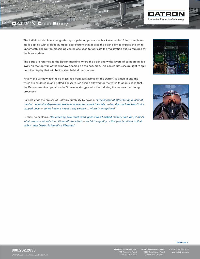
The individual displays then go through a painting process — black over white. After paint, letter-
ing is applied with a diode-pumped laser system that ablates the black paint to expose the white
underneath. The Datron machining center was used to fabricate the registration fixture required for
the laser system.
The parts are returned to the Datron machine where the black and white layers of paint are milled
away on the top wall of the window opening on the back side. This allows NVG secure light to spill
onto the display that will be installed behind the window.
Finally, the window itself (also machined from cast acrylic on the Datron) is glued in and the
wires are soldered in and potted. The Aero-Tec design allowed for the wires to go in last so that
the Datron machine operators don’t have to struggle with them during the various machining
processes.
Harbert sings the praises of Datron’s durability by saying, “I really cannot attest to the quality of
the Datron service department because a year and a half into this project the machine hasn’t hic-
cupped once — so we haven’t needed any service ... which is exceptional.”
Further, he explains, “It’s amazing how much work goes into a finished military part. But, if that’s
what keeps us all safe then it’s worth the effort — and if the quality of this part is critical to that
safety, then Datron is literally a lifesaver.”