Embed Size (px)
Citation preview
Engineering chiral light–matter interaction in photonic crystal waveguides with slowlight
Sahand Mahmoodian,1 Kasper Prindal-Nielsen,1 Immo Sollner,1 Søren Stobbe,1 and Peter Lodahl1
1Niels Bohr Institute, University of Copenhagen,Blegdamsvej 17, DK-2100 Copenhagen, Denmark
(Dated: October 5, 2016)
We design photonic crystal waveguides with efficient chiral light–matter interfaces that can beintegrated with solid-state quantum emitters. By using glide-plane-symmetric waveguides, we showthat chiral light-matter interaction can exist even in the presence of slow light with slow-down factorsof up to 100 and therefore the light–matter interaction exhibits both strong Purcell enhancementand chirality. This allows for near-unity directional β-factors for a range of emitter positions andfrequencies. Additionally, we design an efficient mode adapter to couple light from a standardnanobeam waveguide to the glide-plane symmetric photonic crystal waveguide. Our work sets thestage for performing future experiments on a solid-state platform.
INTRODUCTION
Waveguide quantum electrodynamics (WQED) is an attractive platform for performing experiments where a one-dimensional continuum of radiation modes interacts strongly with quantum emitters [1]. This platform has been usedto demonstrate efficient single-photon generation [2, 3], few-photon nonlinearities [4], and atom–atom interactions neara photonic band edge [5]. The dynamics of a WQED system is ideally governed by the decay rate of the quantumemitter into the right ΓR and left ΓL propagating modes of the waveguide, however the quantum emitter generallyalso couples to a continuum of radiation modes outside the waveguide with a rate γ. This acts as a loss which spoilsthe ideal interaction of the emitter with the guided one-dimensional reservoir. Accordingly, much research has beendevoted to designing light–matter interfaces that maximize the fraction of light emitted from the quantum emitter tothe waveguide mode [6–9]. This is known as the beta factor β = (ΓR + ΓL)/(ΓR + ΓL + γ). Nanophotonic waveguidescomposed of high refractive index materials have strongly confined optical modes and when patterned with photonicnanostructures can both suppress coupling to radiation modes using a photonic bandgap and further enhance couplingto the waveguide mode by reducing its group velocity vg. Such systems can be efficiently combined with solid-statequantum emitters such as quantum dots [9] with near-unity values of β being demonstrated recently [2].
An exciting development in WQED systems is the demonstration of chiral light–matter interaction, i.e., whenthe symmetry between emission into the right- and left-propagating modes is broken ΓR 6= ΓL [10–13]. Since theHamiltonian in these systems is not symmetric under time-reversal [14], they can be used to construct optical isolatorsand circulators [11, 15–17] as well as to dissipatively prepare entangled states in a cascaded spin network [14, 18]. Inthe extreme case this interaction can also become unidirectional, i.e., the emitter couples only to a single direction.Unidirectional emission occurs when the transition dipole moment of the emitter couples to the waveguide mode inone direction while being orthogonal to the mode in the other direction. This has been achieved by engineering themodes of the nanophotonic waveguide to have an in-plane circular polarization. The modes of a dielectric waveguideare time-reversal symmetric and therefore ω−k = ωk and E−k(r) = E∗
k(r) implying that counter-propagating modesare counter circulating. An ideal WQED system with a chiral light-matter interface exhibits unidirectional emissionand also minimizes the coupling fraction to radiation modes. The fraction of light coupled to a single directional modeis characterized by the directional beta factor βR/L = ΓR/L/(ΓR + ΓL + γ) [13], where the subscripts R and L referto right or left respectively. In this manuscript we show that an ideal chiral light-matter interface can be achievedin a glide-plane waveguide. Unlike in previous work [11, 19, 20], we show that in-plane circular polarization can bepreserved in photonic crystal waveguides with glide-plane symmetry (GPWs) for group velocities as low as vg ∼ c/100and that the waveguide has only a single mode. This requires carefully engineering the glide-plane waveguide toensure that it only has a single mode while preserving its symmetry. By computing the emission properties of a dipoleembedded in the waveguide, we show that the decay rate of emission to a single directional mode can be enhanced bya factor of 5 while maintaining directional beta factors of βR/L > 0.99. Finally, we design an efficient mode adapterto couple between a regular suspended nanobeam waveguide and our GPW.
arX
iv:1
610.
0104
6v1
[ph
ysic
s.op
tics]
4 O
ct 2
016
2
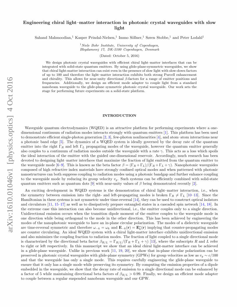
FIG. 1. Schematics of travelling and standing waves in a two-dimensional nanophotonic waveguide. (a) A TE mode (electricfield in x-y plane) of a high-index waveguide (n1 > n2) propagating to the right with propagation constant k. This mode hasa longitudinal electric field component that is π/2 out of phase with the transverse component and its magnitude is relatedto the confinement of the mode. With appropriate design the field can be circularly polarized. (b) An interference patterncomposed of counter-propagating modes of the waveguide in (a) with wavevectors ±k. The resultant mode has electric fieldsthat are real and the cannot have in-plane circular polarization.
ENGINEERING LIGHT-MATTER INTERACTION IN GLIDE-PLANE WAVEGUIDES
Before presenting our design we briefly discuss the requirements for realizing a waveguide whose modes have an in-plane circular polarization. The first requirement is that the waveguide modes have a longitudinal field component thusrequiring non-paraxial wave propagation. The longitudinal field component must also be π/2 out of phase with thetransverse field component. Fortunately, it has been shown that the magnitude of the longitudinal component of theelectric field of a confined mode is proportional to the strength of its transverse confinement [13, 21] and that Gauss’sLaw ensures that the longitudinal component is π/2 out of phase with the transverse component. This is illustratedin a simple example in Fig. 1(a) which shows a schematic of the field in a two-dimensional nanophotonic waveguide.
Since the geometry is piecewise homogeneous, within the waveguide Gauss’s Law requires that ∂Ex
∂x +∂Ey
∂y = 0.
The field of the waveguide is given by Ek(r) = [Ex(y)x + Ey(y)y] eikx and therefore the waveguide mode must
possess a longitudinal field component given by Ex = ik∂Ey
∂y . We note that this argument only holds if eigenstatesof the waveguide are forward and backward propagating modes. If the forward and backward propagating states arecoupled, for example by creating a cavity, the mode becomes a linear combination of these states. The limit of wherethe eigenmodes are complete standing-waves is shown in Fig. 1(b). Here, since the mode is a linear combination ofthe forward Ek and backward E−k = E∗
k propagating modes, it becomes a real-valued field and cannot possess anin-plane circular polarization.
Although photonic-crystal waveguide (PCW) modes are more complex than the simple schematic shown in Fig. 1,the same arguments can be used to determine whether its modes have an in-plane circular polarization. Importantly,the presence of a band-edge occurring at the Brillouin zone (BZ) boundary k = π/a, where k is the Bloch wavevectorand a is the lattice period, sets the same restrictions on the mode profile [22]. In particular, if the dispersion isquadratic the field becomes a real-valued standing wave and does not have circularly polarized modes [20]. Thisfollows due to time-reversal symmetry and crystal periodicity giving the relation
E∗π/a(r) = E−π/a(r) = Eπ/a(r), (1)
as the two zone edges are separated by a reciprocal lattice vector 2π/a. This means that regular PCWs have modesthat are standing waves near the band-edge and cannot have an in-plane circular polarization. We emphasize thatthe behaviour near the band edge is of importance as this is the regime of slow light.
This constraint can be overcome by introducing glide-plane symmetry to the waveguide. A glide-plane operationis a reflection about a plane followed by a translation. Figure 2(a) shows a GPW that is invariant under a reflectionabout the x-z plane followed by a translation of a/2 along the x-direction. We denote the glide-plane operatorG = Tx=a/2Ry, where Tx=a/2 is the half-period translation operator and Ry is the reflection operator. Since the
GPW is invariant under the operation G, its electric field eigenstates Ek(r) are also eigenstates of G. To find theeigenvalues of G, we note that two glide-plane operations correspond to a translation along a unit cell. ThereforeG2Ek(r) = eikaEk(r) and thus GEk(r) = ±eika/2Ek(r). Importantly, at the Brillouin zone edge k = π/a and thus the
3
−2 −1 0 1 2
−3
−2
−1
0
1
2
3
−2 −1 0 1 2
−3
−2
−1
0
1
2
3
0.25 0.3 0.35 0.4 0.45 0.50.24
0.26
0.28
0.3
0.32
0.34
0.25 0.3 0.35 0.4 0.45 0.50.24
0.26
0.28
0.3
0.32
0.34
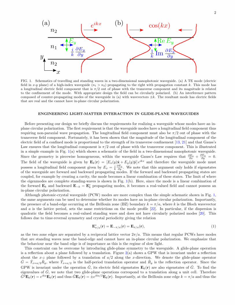
FIG. 2. Glide-plane waveguide geometries and their dispersion curves. (a) A GPW in a triangular lattice with hole-to-hole-centre width of 0.75
√3a and (b) its dispersion curve. The blue lines are the waveguide modes and the grey shading indicates
modes not guided by the waveguide. (c) A GPW dispersion engineered to have only a single mode propagating in each directionand (d) its dispersion curve. The dashed blue lines show other modes that are not of interest. See main text for waveguideparameters.
eigenvalues of the glide-plane operator are ±i. This means that two positions in the GPW separated by a glide-planesymmetry operation differ by a factor of ±i and therefore the field cannot be entirely real at the zone edge. To satisfytime-reversal symmetry there must be a second mode at the zone edge with the same frequency which is related tothe first through
E1,π/a(r) = E∗2,π/a(r). (2)
In contrast to Eq. 1 this generally implies that E1,π/a(r) and E2,π/a(r) are complex fields and does not constrain theirpolarization properties. Under these conditions the modes generally have a linear dispersion relation with equal andopposite group velocities at the Brillouin zone boundary.
A schematic of a GPW with a hole-to-hole-centre width of 0.75√
3a between the centre of holes on the two sidesof the waveguide is shown in Fig. 2(a) with its dispersion curve shown in Fig. 2(b). For all calculations the radii ofthe cylinders are r = 0.3a unless otherwise stated, the membrane thickness is t = 0.6154a with a refractive index ofn = 3.464 corresponding to GaAs at cryogenic temperatures. All dispersion curves are for three-dimensional structuresand are computed using freely available software [23]. As predicted, the combination of time-reversal symmetry andglide-plane symmetry causes a degeneracy at the BZ boundary. Unfortunately, the dispersion curve has multiplemodes as the two curves cross in Fig. 2(b). We note the difference to topologically-protected edge states, which canbe designed to guarantee a single Dirac point [24]. This is problematic because, due to Eq. 2, the two modes willtend to have opposite handed circular polarizations at a given position and therefore at such a position an emitterwill couple to two counter-propagating modes destroying the directionality of the system.
To make this waveguide optimum for chiral light-matter interaction we must engineer the dispersion of the waveguide[25] to ensure that the waveguide bands are single moded. This involves changing the radius and position of the holesaround the waveguide. Since the electric field Ek(r) has different field profiles along the dispersion curve, perturbationsto the holes affect the frequency of the modes at different wavevectors differently, i.e., the perturbation matrix element〈Ek|δε|Ek〉 varies with k, where δε is some perturbation to the permittivity distribution of the GPW. We vary the holepositions and radii until the bands have the desired single mode dispersion. The GPW schematic shown in Fig. 2(c)has been engineered to have the single mode dispersion curve shown in Fig. 2(d). We end up with a design whererows two to four are shifted outwards by l2 = 0.25a
√3/2, l3 = 0.2a
√3/2, and l4 = 0.1a
√3/2, and the radii of the
first three rows of holes are modified to r1 = 0.35a, r2 = 0.35a, and r3 = 0.24a.
RESULTS
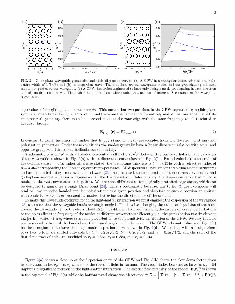
Figure 3(a) shows a close-up of the dispersion curve of the GPW and Fig. 3(b) shows the slow-down factor givenby the group index ng = c/vg where c is the speed of light in vacuum. The group index becomes as large as ng = 94implying a significant increase in the light-matter interaction. The electric field intensity of the modes |E(r)|2 is shown
in the top panel of Fig. 3(c) while the bottom panel shows the directionality D =[|E∗(r) · l|2 − |E∗(r) · r|2
]/|E(r)|2,
4
0.3 0.4 0.50.27
0.28
0.29
0.3
0.31
0.27 0.28 0.29 0.3 0.310
20
40
60
80
100
-0.5 0 0.5 -0.5 0 0.5 -0.5 0 0.5 -0.5 0 0.5 -0.5 0 0.5
-1
0
1
-0.5 0 0.5 -0.5 0 0.5 -0.5 0 0.5 -0.5 0 0.5 -0.5 0 0.5
-1
0
1
-1
0
1
-1
0
1
-1
0
1
-1
0
1
-1
0
1
-1
0
1
-1
0
1
-1
0
1
0
1
-1
1
0
FIG. 3. (a) The dispersion curve of the GPW and (b) the magnitude of the group index of its modes versus frequency for thestructure in Fig. 2(c). (c) The electric field intensity |E|2 (top row) and the directionality factor D (bottom row) for modesalong the dispersion curve with normalized frequencies and group indices (i) a/λ = 0.282 and ng = 23 (ii) a/λ = 0.284 andng = 94 (iii) a/λ = 0.285 and ng = 43 (iv) a/λ = 0.287 and ng = 16 (v) a/λ = 0.298 and ng = 6.
with r = (x + iy)/√
2 and l = (x − iy)/√
2 where x and y are unit vectors. Since there is only one GPW mode,D determines the fraction of light emitted to the right or left within the waveguide, i.e., D = 1 implies the fieldis entirely left-hand circularly polarized, D = −1 implies the field is entirely right-hand circularly polarized whileD = 0 corresponds to linear polarization. Therefore an emitter with a circularly polarized transition dipole momentpositioned at a point with |D| = 1 will emit unidirectionally within the waveguide mode. We highlight that thereare many positions with |D| ∼ 1 for all frequencies and even for group indices up to ng = 94. Importantly the shapeof the Bloch modes is also such that the field has a significant fraction of its maximum intensity near the positionswhere the field is circularly polarized. A quantum dot that is well-coupled to the mode is therefore also likely to beat a position of high directionality.
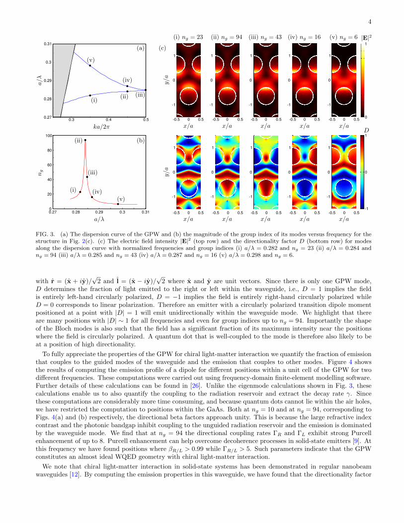
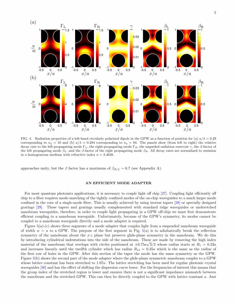
To fully appreciate the properties of the GPW for chiral light-matter interaction we quantify the fraction of emissionthat couples to the guided modes of the waveguide and the emission that couples to other modes. Figure 4 showsthe results of computing the emission profile of a dipole for different positions within a unit cell of the GPW for twodifferent frequencies. These computations were carried out using frequency-domain finite-element modelling software.Further details of these calculations can be found in [26]. Unlike the eigenmode calculations shown in Fig. 3, thesecalculations enable us to also quantify the coupling to the radiation reservoir and extract the decay rate γ. Sincethese computations are considerably more time consuming, and because quantum dots cannot lie within the air holes,we have restricted the computation to positions within the GaAs. Both at ng = 10 and at ng = 94, corresponding toFigs. 4(a) and (b) respectively, the directional beta factors approach unity. This is because the large refractive indexcontrast and the photonic bandgap inhibit coupling to the unguided radiation reservoir and the emission is dominatedby the waveguide mode. We find that at ng = 94 the directional coupling rates ΓR and ΓL exhibit strong Purcellenhancement of up to 8. Purcell enhancement can help overcome decoherence processes in solid-state emitters [9]. Atthis frequency we have found positions where βR/L > 0.99 while ΓR/L > 5. Such parameters indicate that the GPWconstitutes an almost ideal WQED geometry with chiral light-matter interaction.
We note that chiral light-matter interaction in solid-state systems has been demonstrated in regular nanobeamwaveguides [12]. By computing the emission properties in this waveguide, we have found that the directionality factor
5
-0.5 0 0.5
1
0
-1
1
0
-1
1
0
-1
1
0
-1
1
0
-1-0.5 0 0.5 -0.5 0 0.5 -0.5 0 0.5 -0.5 0 0.5
0
0.5
1
1.5
0
0.5
1
1.5
0
0.01
0.02
0.03
0
0.5
1
0
0.5
1
-0.5 0 0.5
1
0
-1
1
0
-1
1
0
-1
1
0
-1
1
0
-1-0.5 0 0.5 -0.5 0 0.5 -0.5 0 0.5 -0.5 0 0.5
0
4
8
0
4
8
0
0.01
0.02
0.03
0
0.5
1
0
0.5
1
FIG. 4. Radiation properties of a left-hand circularly polarized dipole in the GPW as a function of position for (a) a/λ = 0.29corresponding to ng = 10 and (b) a/λ = 0.284 corresponding to ng = 94. The panels show (from left to right) the relativedecay rate to the left-propagating mode ΓL, the right-propagating mode ΓR, the unguided radiation reservoir γ, the β-factor ofthe left propagating mode βL, and the β-factor of the right propagating mode βR. All decay rates are normalized to emissionin a homogeneous medium with refractive index n = 3.4638.
approaches unity, but the β factor has a maximum of βR/L ∼ 0.7 (see Appendix A).
AN EFFICIENT MODE ADAPTER
For most quantum photonics applications, it is necessary to couple light off chip [27]. Coupling light efficiently offchip to a fiber requires mode-matching of the tightly confined modes of the on-chip waveguides to a much larger modeconfined in the core of a single-mode fiber. This is usually achieved by using inverse tapers [28] or specially designedgratings [29]. These tapers and gratings usually complemented with standard ridge waveguides or underetchednanobeam waveguides, therefore, in order to couple light propagating in a GPW off-chip we must first demonstrateefficient coupling to a nanobeam waveguide. Unfortunately, because of the GPW’s symmetry, its modes cannot becoupled to a nanobeam waveguide directly and a mode adapter is required.
Figure 5(a)-(c) shows three segments of a mode adapter that couples light from a suspended nanobeam waveguideof width w = a to a GPW. The purpose of the first segment in Fig. 5(a) is to adiabatically break the reflectionsymmetry of the nanobeam about the x-z plane but preserve glide-plane symmetry in the nanobeam. We do thisby introducing cylindrical indentations into the side of the nanobeam. These are made by removing the high indexmaterial of the nanobeam that overlaps with circles positioned at ±0.75a
√3/2 whose radius starts at R1 = 0.23a
and increases linearly until the twelfth cylinder which has radius R12 = 0.35a which is the same as the radius ofthe first row of holes in the GPW. After this section of the taper the mode has the same symmetry as the GPW.Figure 5(b) shows the second part of the mode adapter where the glide-plane symmetric nanobeam couples to a GPWwhose lattice constant has been stretched to 1.07a. The lattice stretching has been used for regular photonic crystalwaveguides [30] and has the effect of shifting the dispersion curve lower. For the frequencies of interest this means thatthe group index of the stretched region is lower and ensures there is not a significant impedance mismatch betweenthe nanobeam and the stretched GPW. This can then be directly coupled to the GPW with lattice constant a. Just
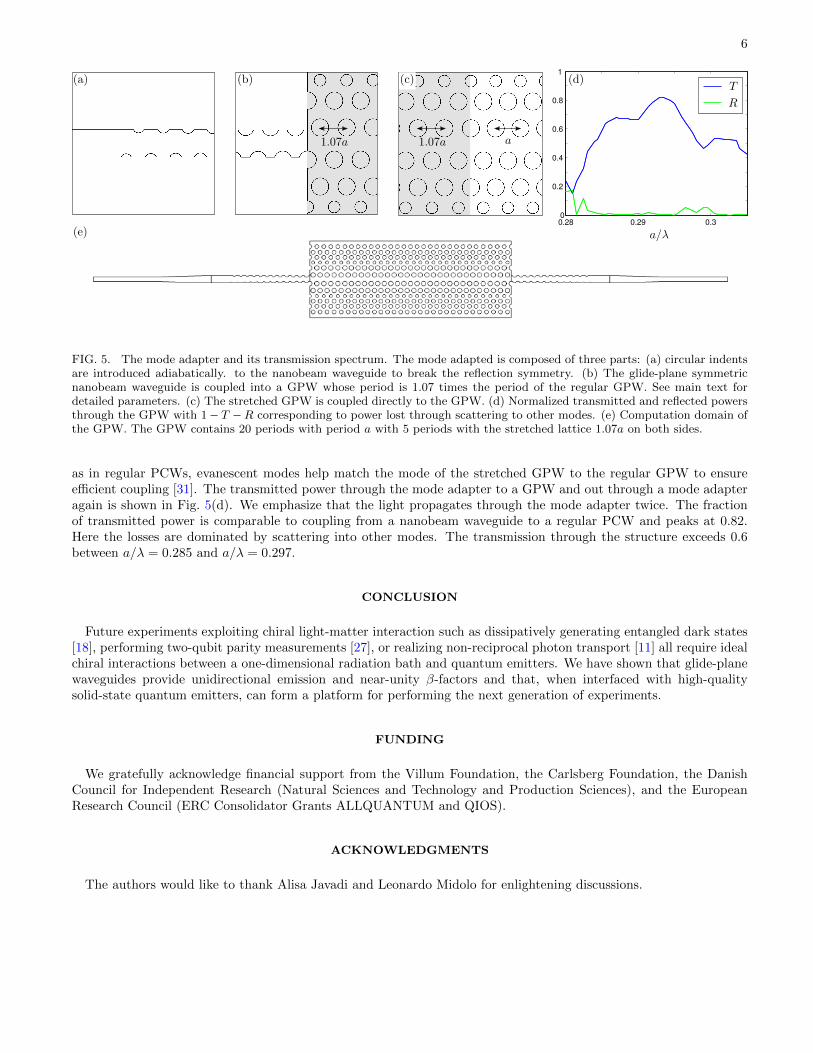
6
0.28 0.29 0.30
0.2
0.4
0.6
0.8
1
FIG. 5. The mode adapter and its transmission spectrum. The mode adapted is composed of three parts: (a) circular indentsare introduced adiabatically. to the nanobeam waveguide to break the reflection symmetry. (b) The glide-plane symmetricnanobeam waveguide is coupled into a GPW whose period is 1.07 times the period of the regular GPW. See main text fordetailed parameters. (c) The stretched GPW is coupled directly to the GPW. (d) Normalized transmitted and reflected powersthrough the GPW with 1− T −R corresponding to power lost through scattering to other modes. (e) Computation domain ofthe GPW. The GPW contains 20 periods with period a with 5 periods with the stretched lattice 1.07a on both sides.
as in regular PCWs, evanescent modes help match the mode of the stretched GPW to the regular GPW to ensureefficient coupling [31]. The transmitted power through the mode adapter to a GPW and out through a mode adapteragain is shown in Fig. 5(d). We emphasize that the light propagates through the mode adapter twice. The fractionof transmitted power is comparable to coupling from a nanobeam waveguide to a regular PCW and peaks at 0.82.Here the losses are dominated by scattering into other modes. The transmission through the structure exceeds 0.6between a/λ = 0.285 and a/λ = 0.297.
CONCLUSION
Future experiments exploiting chiral light-matter interaction such as dissipatively generating entangled dark states[18], performing two-qubit parity measurements [27], or realizing non-reciprocal photon transport [11] all require idealchiral interactions between a one-dimensional radiation bath and quantum emitters. We have shown that glide-planewaveguides provide unidirectional emission and near-unity β-factors and that, when interfaced with high-qualitysolid-state quantum emitters, can form a platform for performing the next generation of experiments.
FUNDING
We gratefully acknowledge financial support from the Villum Foundation, the Carlsberg Foundation, the DanishCouncil for Independent Research (Natural Sciences and Technology and Production Sciences), and the EuropeanResearch Council (ERC Consolidator Grants ALLQUANTUM and QIOS).
ACKNOWLEDGMENTS
The authors would like to thank Alisa Javadi and Leonardo Midolo for enlightening discussions.
7
−0.5 0 0.5−1
0
1
−0.5 0 0.50
0.2
0.4
0.6
0.8
1
−2 0 2−2
0
2
-1 1
−1
1
0
1
FIG. 6. Chiral light-matter interaction in a nanobeam waveguide. (a) Electric field intensity along the cross section of ananobeam waveguide with width w and thickness t = 0.9w. (b) Directionality function of a left-hand circularly polarized dipolepositioned along the green line shown in figure (a). (c) Directional beta factors for a left hand circularly polarized dipole alongthe waveguide. All computations are at a normalized frequency of w/λ = 0.215.
Appendix
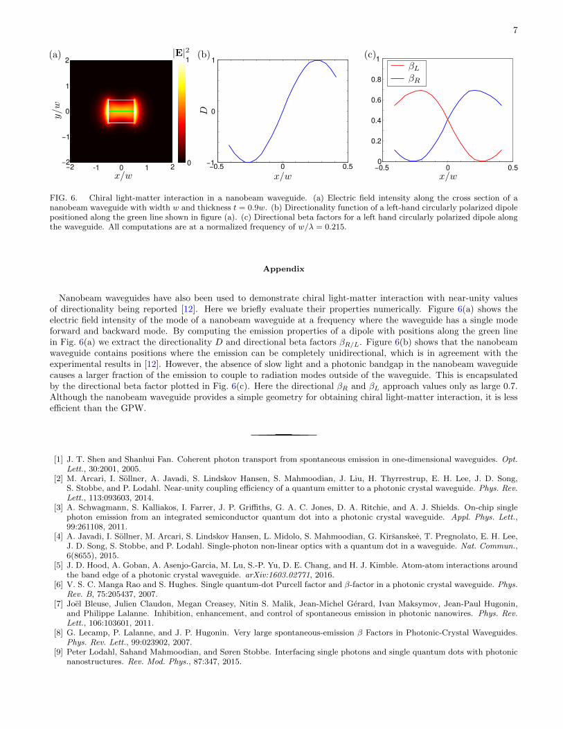
Nanobeam waveguides have also been used to demonstrate chiral light-matter interaction with near-unity valuesof directionality being reported [12]. Here we briefly evaluate their properties numerically. Figure 6(a) shows theelectric field intensity of the mode of a nanobeam waveguide at a frequency where the waveguide has a single modeforward and backward mode. By computing the emission properties of a dipole with positions along the green linein Fig. 6(a) we extract the directionality D and directional beta factors βR/L. Figure 6(b) shows that the nanobeamwaveguide contains positions where the emission can be completely unidirectional, which is in agreement with theexperimental results in [12]. However, the absence of slow light and a photonic bandgap in the nanobeam waveguidecauses a larger fraction of the emission to couple to radiation modes outside of the waveguide. This is encapsulatedby the directional beta factor plotted in Fig. 6(c). Here the directional βR and βL approach values only as large 0.7.Although the nanobeam waveguide provides a simple geometry for obtaining chiral light-matter interaction, it is lessefficient than the GPW.
[1] J. T. Shen and Shanhui Fan. Coherent photon transport from spontaneous emission in one-dimensional waveguides. Opt.Lett., 30:2001, 2005.
[2] M. Arcari, I. Sollner, A. Javadi, S. Lindskov Hansen, S. Mahmoodian, J. Liu, H. Thyrrestrup, E. H. Lee, J. D. Song,S. Stobbe, and P. Lodahl. Near-unity coupling efficiency of a quantum emitter to a photonic crystal waveguide. Phys. Rev.Lett., 113:093603, 2014.
[3] A. Schwagmann, S. Kalliakos, I. Farrer, J. P. Griffiths, G. A. C. Jones, D. A. Ritchie, and A. J. Shields. On-chip singlephoton emission from an integrated semiconductor quantum dot into a photonic crystal waveguide. Appl. Phys. Lett.,99:261108, 2011.
[4] A. Javadi, I. Sollner, M. Arcari, S. Lindskov Hansen, L. Midolo, S. Mahmoodian, G. Kirsanskee, T. Pregnolato, E. H. Lee,J. D. Song, S. Stobbe, and P. Lodahl. Single-photon non-linear optics with a quantum dot in a waveguide. Nat. Commun.,6(8655), 2015.
[5] J. D. Hood, A. Goban, A. Asenjo-Garcia, M. Lu, S.-P. Yu, D. E. Chang, and H. J. Kimble. Atom-atom interactions aroundthe band edge of a photonic crystal waveguide. arXiv:1603.02771, 2016.
[6] V. S. C. Manga Rao and S. Hughes. Single quantum-dot Purcell factor and β-factor in a photonic crystal waveguide. Phys.Rev. B, 75:205437, 2007.
[7] Joel Bleuse, Julien Claudon, Megan Creasey, Nitin S. Malik, Jean-Michel Gerard, Ivan Maksymov, Jean-Paul Hugonin,and Philippe Lalanne. Inhibition, enhancement, and control of spontaneous emission in photonic nanowires. Phys. Rev.Lett., 106:103601, 2011.
[8] G. Lecamp, P. Lalanne, and J. P. Hugonin. Very large spontaneous-emission β Factors in Photonic-Crystal Waveguides.Phys. Rev. Lett., 99:023902, 2007.
[9] Peter Lodahl, Sahand Mahmoodian, and Søren Stobbe. Interfacing single photons and single quantum dots with photonicnanostructures. Rev. Mod. Phys., 87:347, 2015.
8
[10] Jan Petersen, Jurgen Volz, and Arno Rauschenbeutel. Chiral nanophotonic waveguide interface based on spin-orbitinteraction of light. Science, 346:67, 2014.
[11] Immo Sollner, Sahand Mahmoodian, Sofie Lindskov Hansen, Leonardo Midolo, Gabija Kirsanske, Tomamaso Pregnolato,Haitham El-Ella, Eun Hye Lee, Jin Dong Song, Søren Stobbe, and Peter Lodahl. Deterministic photon–emitter couplingin chiral photonic circuits. Nat. Nanotechnol., 10:775, 2015.
[12] R. J. Coles, D. M. Price, J. E. Dixon, B. Royall, E. Clarke, P. Kok, M. S. Skolnick, A. M. Fox, and M. N. Makhonin.Chirality of nanophotonic waveguide with embedded quantum emitter for unidirectional spin transfer. Nat. Commun., 7,2016.
[13] Peter Lodahl, Sahand Mahmoodian, Søren Stobbe, Philipp Schneeweiss, Jurgen Volz, Arno Rauschenbeutel, HannesPichler, and Peter Zoller. Chiral quantum optics. arXiv:1608.00446, 2016.
[14] K. Stannigel, P. Rabl, and P. Zoller. Driven-dissipative preparation of entangled states in cascaded quantum-opticalnetworks. New J. Phys., 14(6):063014, 2012.
[15] Keyu Xia, Guowei Lu, Gongwei Lin, Yuqing Cheng, Yueping Niu, Shangqing Gong, and Jason Twamley. Reversiblenonmagnetic single-photon isolation using unbalanced quantum coupling. Phys. Rev. A, 90:043802, 2014.
[16] Clement Sayrin, Christian Junge, Rudolf Mitsch, Bernhard Albrecht, Danny O’Shea, Philipp Schneeweiss, Jurgen Volz,and Arno Rauschenbeutel. Nanophotonic optical isolator controlled by the internal state of cold atoms. Phys. Rev. X,5:041036, Dec 2015.
[17] Michael Scheucher, Adele Hilico, Elisa Will, Jurgen Volz, and Arno Rauschenbeutel. Quantum optical circulator controlledby a single chirally coupled atom. arXiv:1609.02492, 2016.
[18] Hannes Pichler, Tomas Ramos, Andrew J. Daley, and Peter Zoller. Quantum optics of chiral spin networks. Phys. Rev.A, 91:042116, Apr 2015.
[19] A. B. Young, A. C. T. Thijssen, D. M. Beggs, P. Androvitsaneas, L. Kuipers, J. G. Rarity, S. Hughes, and R. Oulton.Polarization engineering in photonic crystal waveguides for spin-photon entanglers. Phys. Rev. Lett., 115:153901, 2015.
[20] Ben Lang, Daryl M. Beggs, and Ruth Oulton. Time reversal constraint limits unidirectional photon emission in slow-lightphotonic crystals. arXiv:1601.04591, 2016.
[21] Konstantin Y. Bliokh and Franco Nori. Transverse spin of a surface polariton. Phys. Rev. A, 85(6):061801, 2012.[22] A. A. Sukhorukov, S. Ha, A. S. Desyatnikov, A. V. Lavrinenko, and Y. S. Kivshar. Slow-light vortices in periodic
waveguides. J. Opt. A, 11(9):094016, 2009.[23] S. G. Johnson and J. D. Joannopoulos. Bloch-iterative frequency-domain methods for maxwell’s equations in a planewave
basis. Opt. Express, 8:173, 2001.[24] M. Z. Hasan and C. L. Kane. Colloquium: Topological insulators. Rev. Mod. Phys., 82:3045, 2010.[25] L. H. Frandsen, A. V. Lavrinenko, J. Fage-Pedersen, and P. I. Borel. Photonic crystal waveguides with semi-slow light and
tailored dispersion properties. Opt. Express, 14:9444, 2005.[26] Alisa Javadi et al. In preparation. 2014.[27] Sahand Mahmoodian, Peter Lodahl, and Anders Søresensen. Quantum networks with chiral light–matter interaction in
waveguides. arXiv:1602.07054, 2016.[28] Justin D Cohen, Sean M Meenehan, and Oskar Painter. Optical coupling to nanoscale optomechanical cavities for near
quantum-limited motion transduction. Optics express, 21(9):11227–11236, 2013.[29] Dirk Taillaert, Frederik Van Laere, Melanie Ayre, Wim Bogaerts, Dries Van Thourhout, Peter Bienstman, and Roel Baets.
Grating couplers for coupling between optical fibers and nanophotonic waveguides. Japanese Journal of Applied Physics,45(8R):6071, 2006.
[30] J. P. Hugonin, P. Lalanne, T. P. White, and T. F. Krauss. Coupling into slow-mode photonic crystal waveguides. Opt.Lett., 32:2638, 2007.
[31] C. Martijn de Sterke, K. B. Dossou, T. P. White, L. C. Botten, and R. C. McPhedran. Efficient coupling into slow lightphotonic crystal waveguide without transition region: role of evanescent modes. Opt. Express, 17:17338, 2009.