Embed Size (px)
Citation preview
Nfias
CCa
b
c
a
ARRAA
KNEIEU
1
beetwentlte
h0
Electrochimica Acta 178 (2015) 80–91
Contents lists available at ScienceDirect
Electrochimica Acta
j our na l ho me pa g e: www.elsev ier .com/ locate /e lec tac ta
ickel-N,N’–bis(salicylidene)-1,3-propanediamine (Ni-Salpn)lm-modified electrodes. Influence of electrodeposition conditionsnd of electrode material on electrochemical behaviour in aqueousolution
ibely S. Martina,b, Carla Gouveia-Caridadeb, Frank N. Crespilhoc, Carlos J.L. Constantinoa,hristopher M.A. Brettb,∗
Departamento de Física, Química e Biologia, Faculdade de Ciências e Tecnologia, UNESP Univ Estadual Paulista, Presidente Prudente-SP, BrazilDepartment of Chemistry, Faculty of Sciences and Technology, University of Coimbra, 3004-535 Coimbra, PortugalInstituto de Química de São Carlos, Universidade de São Paulo, São Carlos-SP, Brazil
r t i c l e i n f o
rticle history:eceived 11 June 2015eceived in revised form 20 July 2015ccepted 21 July 2015vailable online 26 July 2015
eywords:i-Salpn filmslectrodepositionnfluence of electrode material
a b s t r a c t
Modified electrodes based on films of Schiff base complexes are excellent candidates for sensing appli-cations. The influence of the electrode material, glassy carbon, platinum, gold or indium tin oxide,on the electrodeposition of nickel-N,N’–bis(salicylidene)-1,3-propanediamine (Ni-Salpn) films in 1,2-dichloroethane (DCE) was investigated, and their electrochemical behaviour was evaluated by cyclicvoltammetry and electrochemical impedance spectroscopy. The effect of the electrodeposition poten-tial and electrodeposition time on the electrochemical behaviour of Ni-Salpn was examined using glassycarbon as substrate. The film growth process was investigated using the electrochemical quartz crys-tal microbalance and UV-vis absorption spectroscopy and structural differences between the Ni-Salpncomplex and the Ni-Salpn film were examined by micro-Raman spectroscopy. The results demonstrate
QCMV-vis and Raman spectroscopy
that the electrodeposition mechanism is independent of the electrode material, but that the nature ofthe substrate material influences the rate of film growth, the electrochemical behaviour and the stabilityof the film-modified electrodes in aqueous solution. Counteranion insertion during oxidation can breakthe bonds between the complexes in the stacked Ni-Salpn film structure and cause both mass loss andblockage of the redox metal centre activity, but these effects are small in thin films.
. Introduction
Metal-Schiff complexes with tetradentate N2O2 ligands areeing widely studied as modifiers of electrodes by oxidativelectrodeposition on a variety of conducting surfaces [1–4]. Thelectrodeposition mechanism has been extensively discussed inhe literature by Goldsby et al. [5,6] and Audebert et al. [7–9], inhich radical-radical coupling was proposed. However, Vilas-Boas
t al. [10,11] and Dahm et al. [12] concluded that the mecha-ism is based on the interactions between the phenol ring andhe metallic centre with formation of Ni-phenyl stacks. Neverthe-
ess, in both hypotheses, the films are classified as conducting dueo the donor sites (metallic centre) and delocalized redox moi-ties (�-conjugated system), where electron transfer occurs at the∗ Corresponding author. Tel.: +351 239854470; fax: +351 239827703.E-mail address: [email protected] (C.M.A. Brett).
ttp://dx.doi.org/10.1016/j.electacta.2015.07.123013-4686/© 2015 Elsevier Ltd. All rights reserved.
© 2015 Elsevier Ltd. All rights reserved.
metallic centres, leading to important applications in electrochem-ical sensors [4,13–15]. The properties of Schiff films depend on theelectrodeposition conditions, such as structure of the monomer[16,17], electrodeposition mode [18,19], potential range, fixedapplied potential or current [19], the nature of the electrode mate-rial [12], and solvent [5]. Thus, characterization in situ is veryimportant for understanding the electrochemical behaviour of thefilm formed and its interactions with the electrode surface as wellas with species present in solution.
Among the metal-Schiff complexes, the nickel N,N’–bis(salicylidene)-1,3-propanediamine complex (Ni-Salpn) hasbeen used as an antimicrobial agent [20] and as a chelatingagent in complexometric potentiometric titrations [21]. Ni-Salpnwas first electrodeposited by Ardasheva et al. [19] on platinum
electrodes. Since then, no reports on electrodeposited Ni-Salpn arefound in the literature; only a few studies concerning the ligandSalpn in other soluble metal complexes have been reported [22,23].To our knowledge, the influence of the electrode substrate material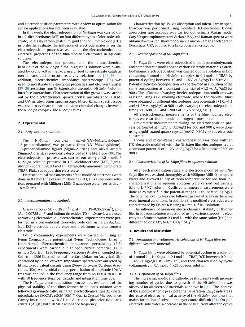
himic
as
isiees
bamau[ioawt
2
2
11(eNA(
dt1
2
(af(e
INeuScficrw
pfmGc
C.S. Martin et al. / Electroc
nd electrodeposition parameters with a view to optimisation forensor applications has not been evaluated.
In this work, the electrodeposition of Ni-Salpn was carried outn 1,2-dichlorethane (DCE) on four different types of electrode sub-trate, i.e. glassy carbon, platinum, gold and indium tin oxide (ITO),n order to evaluate the influence of electrode material on thelectrodeposition process as well as on the electrochemical andlectrical properties of the film-modified electrodes in aqueousolution.
The electrodeposition process and the electrochemicalehaviour of the Ni-Salpn films in aqueous solution were evalu-ted by cyclic voltammetry, a useful tool to investigate catalyticechanisms and structure-reactivity relationships [24–26]. In
ddition, electrochemical impedance spectroscopy (EIS) wassed to investigate the electrical properties and electron transfer27–29] resulting from Ni-Salpn/substrate and/or Ni-Salpn/solutionnterface interactions. Characterization of film growth was carriedut by the electrochemical quartz crystal microbalance (EQCM)nd UV-vis absorption spectroscopy. Micro-Raman spectroscopyas used to evaluate the structural or chemical changes between
he Ni-Salpn complex and Ni-Salpn films.
. Experimental
.1. Reagents and solutions
The Ni-Salpn complex (nickel-N,N’–bis(salicylidene)-,3-propanediamine) was prepared from N,N’–bis(salicylidene)-,3-propanediamine ligand (Sigma-Aldrich) and nickel acetateSigma-Aldrich), as previously described in the literature [30]. Thelectrodeposition process was carried out using a 1.0 mmol L−1
i-Salpn solution prepared in 1,2 -dichloroethane (DCE, Sigma-ldrich) containing 0.1 mol L−1 tetrabutylammonium perchlorate
TBAP, Fluka) as supporting electrolyte.Electrochemical measurements of the modified electrodes were
one in 0.1 mol L−1 potassium chloride (KCl, Fluka) aqueous solu-ion, prepared with Millipore Milli-Q nanopure water (resistivity ≥8 M� cm).
.2. Instrumentation and methods
Glassy carbon, (GC - 0.28 cm2), platinum (Pt–0.0628 cm2), goldAu–0.00785 cm2) and indium tin oxide (ITO ∼ 1.0 cm2), were useds working electrodes. All electrochemical experiments were per-ormed in a conventional three-electrode cell, using an Ag/AgClsat. KCl) electrode as reference and a platinum wire as counterlectrode.
Cyclic voltammetry experiments were carried out using anvium CompactStat.e potentiostat (Ivium Technologies, Utrecht,etherlands). Electrochemical impedance spectroscopy (EIS)xperiments were carried out at open circuit potential (OCP)sing a Solartron 1250 Frequency Response Analyser, coupled to aolartron 1286 Electrochemical Interface (Solartron Analytical, UK)ontrolled by Zplot Software. Impedance spectra were analysed bytting to equivalent circuits using ZView Software (Scribner Asso-iates, USA). A sinusoidal voltage perturbation of amplitude 10 mVms was applied in the frequency range from 65000 Hz to 0.1 Hzith 10 frequency steps per decade, and integration time 60s.
The Ni-Salpn electrodeposition process and evaluation of thehysical stability of the films formed in aqueous solution were
ollowed gravimetrically, using an electrochemical quartz crystalicrobalance (EQCM), eQCM 10MTM Quartz Crystal Microbalance,amry Instruments, with AT-cut Au-coated piezoelectric quartzrystals (AuQC) with 10 MHz resonance frequency.
a Acta 178 (2015) 80–91 81
Characterization by UV-vis absorption and micro-Raman spec-troscopy was performed using modified ITO electrodes. UV-visabsorption spectroscopy was carried out using a Varian modelCary 50 spectrophotometer (Varian, USA), and Raman spectra wereobtained with a Renishaw model in-Via micro-Raman spectrograph(Renishaw, UK), coupled to a Leica optical microscope.
2.3. Electrodeposition of Ni-Salpn films
Ni-Salpn films were electrodeposited in both potentiodynamicand potentiostatic modes on the various electrode materials. Poten-tiodynamic electrodeposition was carried out in a solution in DCEcontaining 1 mmol L−1 Ni-Salpn complex in 0.1 mol L−1 TBAP bypotential cycling between 0.0 and +1.4 V vs. Ag/AgCl at 50 mV s−1.Potentiostatic electrodeposition was performed in a solution of thesame composition at a constant potential of +1.2 vs. Ag/AgCl for900 s. The influence of varying the electrodeposition conditions wasassessed using a GC working electrode, where the Ni-Salpn filmswere obtained at different electrodeposition potentials (+1.0, +1.1and +1.2 V vs. Ag/AgCl at 900 s), also varying the electrodepositiontime (300, 600, 900 and 1200 s at +1.2 V vs. Ag/AgCl).
All electrochemical measurements of the film-modified elec-trodes were carried out under a nitrogen atmosphere.
Gravimetric measurements during the electrodeposition pro-cess performed at +1.2 V vs. Ag/AgCl for 300 and 900 s, were doneusing a gold-coated quartz crystal (AuQC–0.205 cm2) as electrodesubstrate.
UV-vis and micro-Raman characterization was done with anITO electrode modified with the Ni-Salpn film electrodeposited ata constant potential of +1.2 V vs. Ag/AgCl for a fixed time of 300 or900 s.
2.4. Characterization of Ni-Salpn films in aqueous solution
After each modification stage, the electrode modified with Ni-Salpn film was washed thoroughly with Millipore Milli-Q nanopurewater and allowed to dry at room temperature for one hour. Allcharacterizations in aqueous solution were carried out using a0.1 mol L−1 KCl solution. Cyclic voltammetry measurements weredone at 25 mV s−1 in the potential range 0.1 to 0.8 V vs. Ag/AgCl.The potential cycling was also followed gravimetrically in the sameexperimental conditions. In addition, the modified electrodes werecharacterized by EIS at OCP using 0.1 mol L−1 KCl solution.
The influence of anion on electrochemical stability of thinnerfilm in aqueous solution was studied using various supporting elec-trolytes of concentration 0.1 mol L−1with the same cation (Na+) anddifferent anions: Cl−, NO3
−, ClO4−, SO4
2−.
3. Results and Discussion
3.1. Formation and voltammetric behaviour of Ni-Salpn films ondifferent electrode materials
Ni-Salpn films were obtained by potential cycling in a solutionof 1 mmol L−1 Ni-Salpn in 0.1 mol L−1 TBAP/DCE between 0.0 and+1.4 V vs. Ag/AgCl at 50 mV s−1, and then characterised by cyclicvoltammetry in 0.1 mol L−1 KCl aqueous solution.
3.1.1. Deposition of Ni-salpn filmsThe increasing anodic and cathodic peak currents with increas-
ing number of cycles due to growth of the Ni-Salpn film wasobserved for all electrode materials, as shown in Fig. 1. The increase
of the anodic-cathodic peak potential separation (�Ep) indicates adecrease of electrochemical activity of the Ni-Salpn complex thatmakes formation of subsequent layers more difficult [31]. On goldelectrode substrates, a decrease in the peak current after ten cycles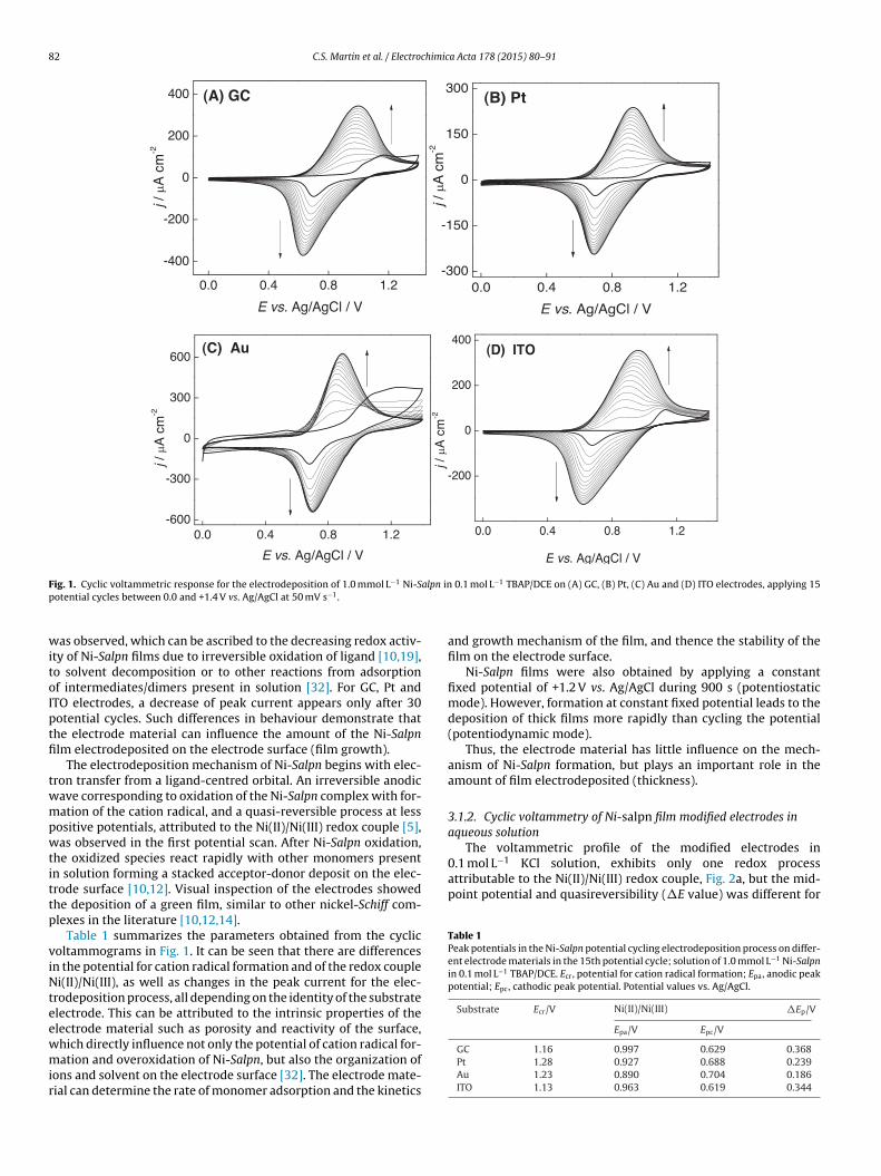
82 C.S. Martin et al. / Electrochimica Acta 178 (2015) 80–91
F alpn inp
witoIptfi
twmpwtittp
viNteewmir
The voltammetric profile of the modified electrodes in0.1 mol L−1 KCl solution, exhibits only one redox processattributable to the Ni(II)/Ni(III) redox couple, Fig. 2a, but the mid-point potential and quasireversibility (�E value) was different for
Table 1Peak potentials in the Ni-Salpn potential cycling electrodeposition process on differ-ent electrode materials in the 15th potential cycle; solution of 1.0 mmol L−1 Ni-Salpnin 0.1 mol L−1 TBAP/DCE. Ecr, potential for cation radical formation; Epa, anodic peakpotential; Epc, cathodic peak potential. Potential values vs. Ag/AgCl.
Substrate Ecr/V Ni(II)/Ni(III) �Ep/V
Epa/V Epc/V
ig. 1. Cyclic voltammetric response for the electrodeposition of 1.0 mmol L−1 Ni-Sotential cycles between 0.0 and +1.4 V vs. Ag/AgCl at 50 mV s−1.
as observed, which can be ascribed to the decreasing redox activ-ty of Ni-Salpn films due to irreversible oxidation of ligand [10,19],o solvent decomposition or to other reactions from adsorptionf intermediates/dimers present in solution [32]. For GC, Pt andTO electrodes, a decrease of peak current appears only after 30otential cycles. Such differences in behaviour demonstrate thathe electrode material can influence the amount of the Ni-Salpnlm electrodeposited on the electrode surface (film growth).
The electrodeposition mechanism of Ni-Salpn begins with elec-ron transfer from a ligand-centred orbital. An irreversible anodicave corresponding to oxidation of the Ni-Salpn complex with for-ation of the cation radical, and a quasi-reversible process at less
ositive potentials, attributed to the Ni(II)/Ni(III) redox couple [5],as observed in the first potential scan. After Ni-Salpn oxidation,
he oxidized species react rapidly with other monomers presentn solution forming a stacked acceptor-donor deposit on the elec-rode surface [10,12]. Visual inspection of the electrodes showedhe deposition of a green film, similar to other nickel-Schiff com-lexes in the literature [10,12,14].
Table 1 summarizes the parameters obtained from the cyclicoltammograms in Fig. 1. It can be seen that there are differencesn the potential for cation radical formation and of the redox couplei(II)/Ni(III), as well as changes in the peak current for the elec-
rodeposition process, all depending on the identity of the substratelectrode. This can be attributed to the intrinsic properties of thelectrode material such as porosity and reactivity of the surface,
hich directly influence not only the potential of cation radical for-ation and overoxidation of Ni-Salpn, but also the organization ofons and solvent on the electrode surface [32]. The electrode mate-ial can determine the rate of monomer adsorption and the kinetics
0.1 mol L−1 TBAP/DCE on (A) GC, (B) Pt, (C) Au and (D) ITO electrodes, applying 15
and growth mechanism of the film, and thence the stability of thefilm on the electrode surface.
Ni-Salpn films were also obtained by applying a constantfixed potential of +1.2 V vs. Ag/AgCl during 900 s (potentiostaticmode). However, formation at constant fixed potential leads to thedeposition of thick films more rapidly than cycling the potential(potentiodynamic mode).
Thus, the electrode material has little influence on the mech-anism of Ni-Salpn formation, but plays an important role in theamount of film electrodeposited (thickness).
3.1.2. Cyclic voltammetry of Ni-salpn film modified electrodes inaqueous solution
GC 1.16 0.997 0.629 0.368Pt 1.28 0.927 0.688 0.239Au 1.23 0.890 0.704 0.186ITO 1.13 0.963 0.619 0.344
C.S. Martin et al. / Electrochimica Acta 178 (2015) 80–91 83
F −1 −1 cycle
( (D) Va
etwefw
sweNe
l
wQ
TA0f
ig. 2. Cyclic voltammetry in 0.1 mol L KCl aqueous solution; v = 25 mV s ; thirdC) Voltammetric response during cycle 5, 10, 15 and 20 for GC electrode substratend ITO electrode substrates.
ach electrode material. The peak potential values obtained fromhe third cycle are presented in Table 2. The GC electrode modifiedith Ni-Salpn film showed the smallest �E value, suggesting that
lectron transfer between the Ni-Salpn film and electrode surface isaster than for the Pt, Au and ITO electrode substrates, and is relatedith the amount of film electrodeposited.
Furthermore, for the same deposition parameters on differentubstrates, Ni-Salpn films with different thicknesses were obtained,hich supports the hypothesis that the electrode material influ-
nces the rate of film growth. The theoretical thickness, l, of thei-Salpn film was estimated for each modified electrode using thequation derived from the Faraday’s law:
= MQ
nFA�
here M is the molecular mass of the monomer (339.02 g mol−1), is the charge, calculated by the integration of the anodic peak
able 2nodic and cathodic peak potentials from cyclic voltammograms obtained in.1 mol L−1 KCl solution for the Ni-Salpn film on different electrode substrates; valuesor 3rd cycle. Potential values vs. Ag/AgCl.
Substrate Ni(II)/Ni(III) Ni(II)/Ni(III)
Epa/V Epc/V �Ep/V *Em/V
GC 0.542 0.433 0.109 0.488Pt 0.534 0.397 0.137 0.466Au 0.630 0.456 0.174 0.543ITO 0.593 0.439 0.154 0.516
* Em = (Epa + Epc)/2
, for GC, Pt, Au and ITO electrodes (A) modified with Ni-Salpn and (B) unmodified.ariation of current density with number of potential cycles for modified GC, Pt, Au
obtained from the cyclic voltammogram in KCl (v = 25 mV s−1), n isthe number of electrons transferred (assumed to be 1), F the Faradayconstant (96485 C mol−1), A the electrode area (in cm2) and � thefilm density (∼1 g cm−3) [4]. The Ni-Salpn film thicknesses were:41 nm on the GC electrode, 18 nm, 12 nm and 2.8 nm for the Au,ITO and Pt electrodes, respectively.
The modified GC electrode showed the greatest film thickness,and highest electron transfer rate (smallest �E). These variationsin behaviour occur due to the specific interaction between the Ni-Salpn film and the electrode material.
The Ni-Salpn films are unstable in aqueous solution, since thepeak currents decrease with increasing number of cycles as shownin Fig. 2b. After 15 potential cycles, the peak currents were approxi-mately equal to those of the bare electrode, where no redox activitywas observed. However, visual inspection showed that the Ni-Salpn film remained on the electrode surface, which suggests thatchanges in the film structure cause blocking of the electrode sur-face.
A possibility is the formation of nickel oxides and/or hydroxides,that lead to loss of redox activity [32]. In addition, ion diffusionfrom bulk electrolyte to inside the Ni-Salpn film may block theredox process, through complexation of nickel centres with speciesfrom solution (chloride ion and/or water ligand). However, thisbehaviour has not been discussed in the literature, and so EIS andgravimetric measurements were performed to better understandthe behaviour of the modified electrode (see below).
A smaller peak current due to oxidation of the Ni-Salpn filmwas observed on Pt and Au, since metallic materials can formoxides in aqueous solutions at potentials less positive than car-bon and conductive oxides [32–34], decreasing the rate of charge
84 C.S. Martin et al. / Electrochimica Acta 178 (2015) 80–91
F difiedM circu
tcfiomtaeazGNop
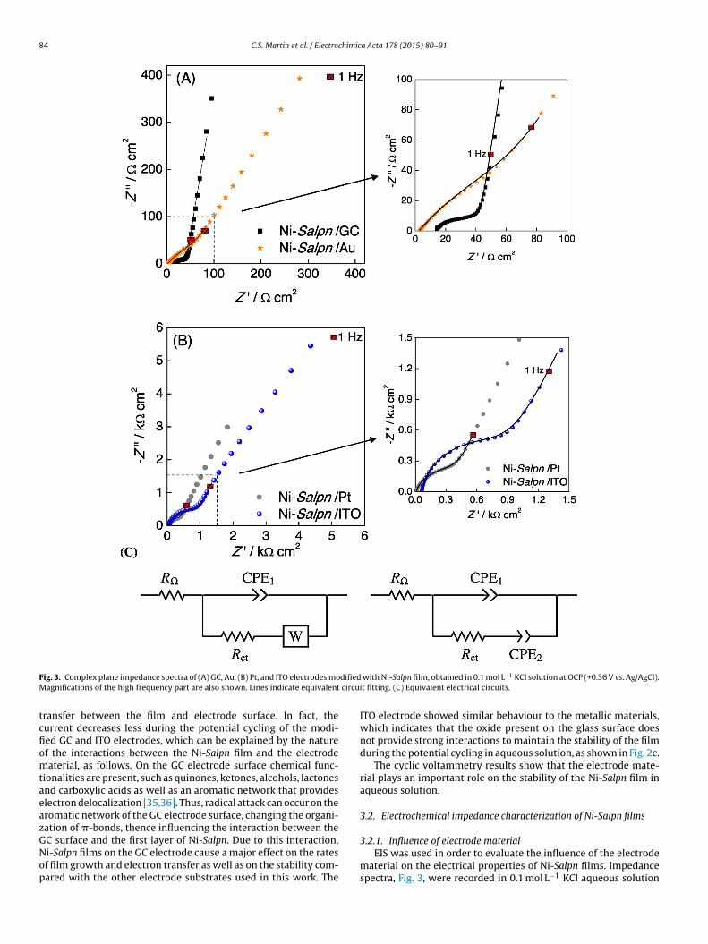
ig. 3. Complex plane impedance spectra of (A) GC, Au, (B) Pt, and ITO electrodes moagnifications of the high frequency part are also shown. Lines indicate equivalent
ransfer between the film and electrode surface. In fact, theurrent decreases less during the potential cycling of the modi-ed GC and ITO electrodes, which can be explained by the naturef the interactions between the Ni-Salpn film and the electrodeaterial, as follows. On the GC electrode surface chemical func-
ionalities are present, such as quinones, ketones, alcohols, lactonesnd carboxylic acids as well as an aromatic network that provideslectron delocalization [35,36]. Thus, radical attack can occur on theromatic network of the GC electrode surface, changing the organi-ation of �-bonds, thence influencing the interaction between the
C surface and the first layer of Ni-Salpn. Due to this interaction,i-Salpn films on the GC electrode cause a major effect on the ratesf film growth and electron transfer as well as on the stability com-ared with the other electrode substrates used in this work. Thewith Ni-Salpn film, obtained in 0.1 mol L−1 KCl solution at OCP (+0.36 V vs. Ag/AgCl).it fitting. (C) Equivalent electrical circuits.
ITO electrode showed similar behaviour to the metallic materials,which indicates that the oxide present on the glass surface doesnot provide strong interactions to maintain the stability of the filmduring the potential cycling in aqueous solution, as shown in Fig. 2c.
The cyclic voltammetry results show that the electrode mate-rial plays an important role on the stability of the Ni-Salpn film inaqueous solution.
3.2. Electrochemical impedance characterization of Ni-Salpn films
3.2.1. Influence of electrode materialEIS was used in order to evaluate the influence of the electrode
material on the electrical properties of Ni-Salpn films. Impedancespectra, Fig. 3, were recorded in 0.1 mol L−1 KCl aqueous solution
C.S. Martin et al. / Electrochimica Acta 178 (2015) 80–91 85
Table 3Parameters obtained from impedance spectra of the electrodes modified with Ni-Salpn film by fitting to the equivalent circuits of Fig. 4; frequency range 65 kHz to 1.0 Hz.
Substrate R�/� cm2 CPE1/�F cm−2 s�−1 �1 Rct/� cm2 CPE2/�F cm−2 s�−1 �2 Rdiff (Wo)/� cm2 �Wo
GC* 13.6 447 0.66 20.6 – – 36.3 0.46GC 13.6 504 0.64 21.2 – – 30.6 0.44Pt 11.5 42.6 0.85 278 – – 601 0.38
aeA
ttawba
cmdwcZcwfhwffwfPfwsacic
piwHnfi
tccafitfs
3
fioE
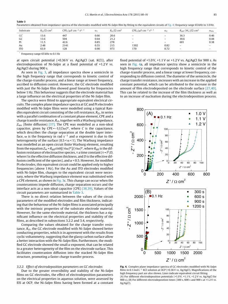
amount of film electrodeposited on the electrode surface [27,40].This can be related to the increase of the film thickness as well asto an increase of nucleation during the electrodeposition process.
Fig. 4. Complex plane impedance spectra of GC electrodes modified with Ni-Salpn
Au 2.48 2141 0.55 215ITO 63.9 128 0.90 973
* Frequency range 65 kHz to 0.1 Hz
t open circuit potential (+0.36 V vs. Ag/AgCl (sat. KCl)), afterlectrodeposition of Ni-Salpn at a fixed potential of +1.2 V vs.g/AgCl during 900 s.
As seen in Fig. 3, all impedance spectra show a semicircle inhe high frequency range that corresponds to kinetic control ofhe charge-transfer process, and a linear range at lower frequency,scribed to diffusion control. However, the GC electrode modifiedith just the Ni-Salpn film showed good linearity for frequencies
elow 1 Hz. This behaviour suggests that the electrode material has large influence on the electrical properties of the Ni-Salpn film.
The spectra were fitted to appropriate equivalent electrical cir-uits. The complex plane impedance spectra at GC and Pt electrodesodified with Ni-Salpn films were modelled using a typical Ran-
les equivalent circuit consisting of the cell resistance, R�, in seriesith a parallel combination of a constant phase element, CPE and a
harge transfer resistance, Rct, together with a Warburg impedance,wo (finite diffusion) [37]. The CPE was modelled as a non-idealapacitor, given by CPE = -1/(Ci�)˛, where C is the capacitance,hich describes the charge separation at the double layer inter-
ace, � is the frequency in rad s−1 and exponent is due to theeterogeneity of the surface (0.5 < � < 1). The Warburg impedanceas modelled as an open circuit finite Warburg element, resulting
rom the equation Zw = Rdifctnh[(�i�)˛]/(�i�)˛, where Rdif is the dif-usion resistance of electroactive species, � a time constant (� = l2/D,here l is the effective diffusion thickness, and D is the effective dif-
usion coefficient of the species), and < 0.5. However, for modifiedt electrodes, this equivalent circuit could be applied only to higherrequencies (above 1 Hz). For the Au and ITO electrodes modifiedith Ni-Salpn film, changes to the equivalent circuit were neces-
ary, where the Warburg impedance element was substituted with CPE element, as shown in Fig. 3c. This change can occur when theounteranions impede diffusion, charge separation occurs and thenterface acts as a non-ideal capacitor (CPE) [38,39]. Values of theircuit parameters are summarized in Table 3.
There is no direct relation between the values of the circuitarameters of the modified electrodes and film thickness, indicat-
ng that the behaviour of the Ni-Salpn films is associated principallyith the intrinsic properties of the substrate electrode material.owever, for the same electrode material, the thickness has a sig-ificant influence on the electrical properties and stability of thelms, as described in subsections 3.2.2 and 3.4, respectively.
Comparing the values obtained for the charge transfer resis-ance, Rct, the GC electrode modified with Ni-Salpn showed betteronducting properties, which is in agreement with the results fromyclic voltammetry, suggesting that the glassy carbon surface allow
better interaction with the Ni-Salpn film. Furthermore, the modi-ed GC electrode showed the small exponent, that can be relatedo a greater heterogeneity of the film on the electrode surface. Thisacilitates counteranion diffusion into the stacked Ni-Salpn filmtructure, promoting a faster charge transfer process.
.2.2. Effect of electrodeposition parameters on GC electrodes
Due to the greater reversibility and stability of the Ni-Salpnlms on GC electrodes, the effect of electrodeposition parametersn the electrical properties in aqueous solution, were assessed byIS at OCP, the Ni-Salpn films having been formed at a constant
1302 0.82 – –170 0.72 – –
fixed potential of +1.0 V, +1.1 V or +1.2 V vs. Ag/AgCl for 900 s. Asseen in Fig. 4a, all impedance spectra show a semicircle in thehigh frequency range that corresponds to kinetic control of thecharge-transfer process, and a linear range at lower frequency, cor-responding to diffusion control. The diameter of the semicircle, thecharge transfer resistance, increases with an increase in the appliedconstant potential, which can be attributed to the increase in the
films in 0.1 mol L−1 KCl solution at OCP (+0.36 V vs. Ag/AgCl). Magnifications of thehigh frequency part are also shown. Lines indicate equivalent circuit fitting.(A) For different electrodeposition potentials (+1.0 V, +1.1 V, +1.2 V vs. Ag/AgCl for900 s), (B) For different electrodeposition times (300 s, 600 s and 900 s at +1.2 V vs.Ag/AgCl).
86 C.S. Martin et al. / Electrochimica Acta 178 (2015) 80–91
Table 4Parameters obtained from impedance spectra at the GC electrode modified with Ni-Salpn film at different electrodeposition potentials, Edep, and electrodeposition times,tdep, by fitting to the equivalent circuits of Fig. 4.
Electrodeposition R�/� cm2 CPE1/�F cm−2 s�−1 � Rct/� cm2 Rdif (Wo)/� cm2 �Wo
During 900 s Edep/V+1.0 15.8 – – – 48.5 0.47+1.1 16.0 516 0.75 16.2 123 0.49+1.2 16.9 535 0.69 48.0 111 0.47
At + 1.2 V tdep/s300 17.4 – – – 14.8 0.48600 17.1 450 0.75 7.80 28.6 0.49
TT
pHimwmstde
iwssTNobp
wtcbsr
wttps
twwc
iFisbtTtti
Shagisultanova and Ardasheva [41] affirmed that films obtainedfrom Ni-Salen (Salen: N,N’-bis(salicylidene)ethylenediamine) andNi-Salphen (Salphen:N,N’-bis(salicylidene)-o-phenylenediamine)complexes can grow on ITO by both continuous and stepwise
NN
OO
Ni
NN
OO
Ni
NN
OO
Ni
NN
OO
Ni
Ni-Salpn
900 16.7 536
1200 16.4 872
he parameters from equivalent circuit fitting are summarized inable 4.
An increase in Rct was also observed with increasing electrode-osition time at +1.2 V vs. Ag/AgCl, as shown in Fig. 4b and Table 4.owever, for 1200 s electrodeposition time, hardly any variation
n the diffusion impedance was seen in relation to 900 s, in agree-ent with cyclic voltammetry results. The same equivalent circuitas able to be applied to all the spectra, which suggests that theolecular organization of the Ni-Salpn film on the GC electrode
urface is the same throughout the electrodeposition. As expected,he apparent charge transfer resistance and constant phase elementepended on the amount of Ni-Salpn film electrodeposited on thelectrode surface.
A decrease in the value of the CPE exponent was observed withncreasing electrodeposition potential and electrodeposition time,
hich indicates an increase in film roughness [25]. This is expectedince the films from Schiff base complex form stack structures,o that a non-uniform film is obtained on the electrode surfaces.herefore, the best electrical properties were observed with thei-Salpn films obtained by electrodeposition applying a potentialf +1.2 V vs. Ag/AgCl for 900 s. In all cases, the Ni-Salpn film is unsta-le in aqueous solution, confirmed by a decrease in current withotential cycling.
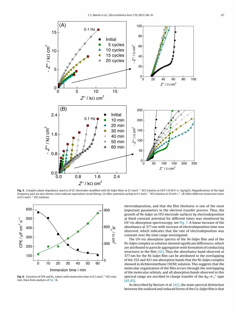
Due to the instability in aqueous solution, impedance spectraere recorded at OCP after each potential cycle and for different
imes of immersion in aqueous solution, Fig. 5. Before potentialycling, the spectra of Ni-Salpn films showed behaviour that coulde modelled by a Randles circuit, but after the fifth cycle in aqueousolution a significant change in both the low and high frequencyange was observed, as shown in Fig. 5a.
The increase in semicircle diameter with potential cycling, asell as the decrease of peak current, observed by cyclic voltamme-
ry (Fig. 2), suggests that ion diffusion from bulk electrolyte throughhe film as well as other effects, such as mass loss, blocks the redoxrocess, since the profiles obtained until the last potential cycle areimilar to those of unmodified GC.
To elucidate the effect of the insertion of the ion from bulk elec-rolyte into the Ni-Salpn film structure, the GC modified electrodeas kept in 0.1 mol L−1 KCl solution and impedance spectra at OCPere recorded for different immersion times (Fig. 6b) together with
yclic voltammograms.The increase in charge transfer resistance, Rct, and the decrease
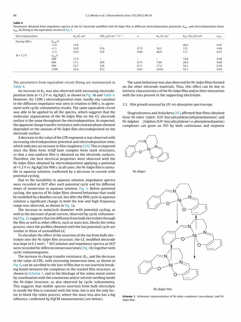
n the value of CPE1 with increasing immersion time, as shown inig. 6, can be ascribed to the loss of film due to ion insertion break-ng bonds between the complexes in the stacked film structure, ashown in Scheme 1, and to the blockage of the redox metal centrey coordination with the counterion and/or solvent swelling insidehe Ni-Salpn structure, as also observed by cyclic voltammetry.
his suggests that mobile species insertion from bulk electrolyteo inside the film is constant with the time, but is not the only fac-or to block the redox process, where the mass loss also has a bignfluence, confirmed by EQCM measurements (see below).0.71 17.4 56.1 0.490.67 24.02 55.1 0.50
The same behaviour was also observed for Ni-Salpn films formedon the other electrode materials. Thus, this effect can be due tointrinsic characteristics of the Ni-Salpn film and/or their interactionwith the ions present in the supporting electrolyte.
3.3. Film growth assessed by UV-vis absorption spectroscopy
Ni-Salpn film
Scheme 1. Schematic representation of Ni-Salpn complexes (non-planar) and Ni-Salpn film.
C.S. Martin et al. / Electrochimica Acta 178 (2015) 80–91 87
Fig. 5. Complex plane impedance spectra of GC electrodes modified with Ni-Salpn films
frequency part are also shown. Lines indicate equivalent circuit fitting. (A) After potential
in 0.1 mol L−1 KCl solution.
Fig. 6. Variation of CPE and Rct values with immersion time in 0.1 mol L−1 KCl solu-t
ion. Data from analysis of Fig. 5b.in 0.1 mol L−1 KCl solution at OCP (+0.36 V vs. Ag/AgCl). Magnifications of the highcycling in 0.1 mol L−1 KCl solution at 25 mV s−1. (B) After different immersion times
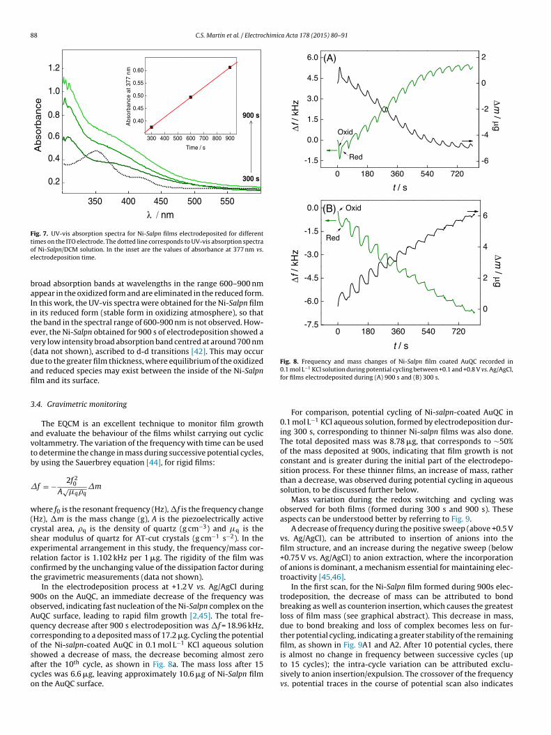
electrodeposition, and that the film thickness is one of the mostimportant parameters in the electron transfer process. Thus, thegrowth of Ni-Salpn on ITO electrode surfaces by electrodepositionat fixed constant potential for different times was monitored byUV-vis absorption spectroscopy, see Fig. 7. A linear increase of theabsorbance at 377 nm with increase of electrodeposition time wasobserved, which indicates that the rate of electrodeposition wasconstant over the time range investigated.
The UV-vis absorption spectra of the Ni-Salpn film and of theNi-Salpn complex in solution showed significant differences, whichare attributed to particle aggregation with formation of conductingstructures in the film [42]. Thus the absorbance band observed at377 nm for the Ni-Salpn film can be attributed to the overlappingof the 352 and 421 nm absorption bands that the Ni-Salpn complexshowed in dichloromethane (DCM) solution. This suggests that themolecular organization of the film occurs through the overlappingof the molecular orbitals, and all absorption bands observed in thisspectral range are ascribed to charge transfer of the d -� * type
M L[42,43].As described by Borisov et al. [42], the main spectral distinctionbetween the oxidized and reduced forms of the Cu-Salpn film is that
88 C.S. Martin et al. / Electrochimica Acta 178 (2015) 80–91
0.4
0.6
0.8
1.0
1.2
350 400 450 500 550
0.2
λ / nm
Ab
sorb
an
ce
300 s
900 s
300 40 0 50 0 60 0 70 0 80 0 900
0.40
0.45
0.50
0.55
0.60
Time / s
Abs
orba
nce
at 3
77 n
m
Fig. 7. UV-vis absorption spectra for Ni-Salpn films electrodeposited for differenttimes on the ITO electrode. The dotted line corresponds to UV-vis absorption spectraoe
baIitev(dafi
3
avtb
�
w(cserct
9oAqcosaco
Fig. 8. Frequency and mass changes of Ni-Salpn film coated AuQC recorded in0.1 mol L−1 KCl solution during potential cycling between +0.1 and +0.8 V vs. Ag/AgCl,
f Ni-Salpn/DCM solution. In the inset are the values of absorbance at 377 nm vs.lectrodeposition time.
road absorption bands at wavelengths in the range 600–900 nmppear in the oxidized form and are eliminated in the reduced form.n this work, the UV-vis spectra were obtained for the Ni-Salpn filmn its reduced form (stable form in oxidizing atmosphere), so thathe band in the spectral range of 600-900 nm is not observed. How-ver, the Ni-Salpn obtained for 900 s of electrodeposition showed aery low intensity broad absorption band centred at around 700 nmdata not shown), ascribed to d-d transitions [42]. This may occurue to the greater film thickness, where equilibrium of the oxidizednd reduced species may exist between the inside of the Ni-Salpnlm and its surface.
.4. Gravimetric monitoring
The EQCM is an excellent technique to monitor film growthnd evaluate the behaviour of the films whilst carrying out cyclicoltammetry. The variation of the frequency with time can be usedo determine the change in mass during successive potential cycles,y using the Sauerbrey equation [44], for rigid films:
f = − 2f 20
A√
�q�q�m
here f0 is the resonant frequency (Hz), �f is the frequency changeHz), �m is the mass change (g), A is the piezoelectrically activerystal area, �q is the density of quartz (g cm−3) and �q is thehear modulus of quartz for AT-cut crystals (g cm−1 s−2). In thexperimental arrangement in this study, the frequency/mass cor-elation factor is 1.102 kHz per 1 �g. The rigidity of the film wasonfirmed by the unchanging value of the dissipation factor duringhe gravimetric measurements (data not shown).
In the electrodeposition process at +1.2 V vs. Ag/AgCl during00s on the AuQC, an immediate decrease of the frequency wasbserved, indicating fast nucleation of the Ni-Salpn complex on theuQC surface, leading to rapid film growth [2,45]. The total fre-uency decrease after 900 s electrodeposition was �f = 18.96 kHz,orresponding to a deposited mass of 17.2 �g. Cycling the potentialf the Ni-salpn-coated AuQC in 0.1 mol L−1 KCl aqueous solution
howed a decrease of mass, the decrease becoming almost zerofter the 10th cycle, as shown in Fig. 8a. The mass loss after 15ycles was 6.6 �g, leaving approximately 10.6 �g of Ni-Salpn filmn the AuQC surface.for films electrodeposited during (A) 900 s and (B) 300 s.
For comparison, potential cycling of Ni-salpn-coated AuQC in0.1 mol L−1 KCl aqueous solution, formed by electrodeposition dur-ing 300 s, corresponding to thinner Ni-salpn films was also done.The total deposited mass was 8.78 �g, that corresponds to ∼50%of the mass deposited at 900s, indicating that film growth is notconstant and is greater during the initial part of the electrodepo-sition process. For these thinner films, an increase of mass, ratherthan a decrease, was observed during potential cycling in aqueoussolution, to be discussed further below.
Mass variation during the redox switching and cycling wasobserved for both films (formed during 300 s and 900 s). Theseaspects can be understood better by referring to Fig. 9.
A decrease of frequency during the positive sweep (above +0.5 Vvs. Ag/AgCl), can be attributed to insertion of anions into thefilm structure, and an increase during the negative sweep (below+0.75 V vs. Ag/AgCl) to anion extraction, where the incorporationof anions is dominant, a mechanism essential for maintaining elec-troactivity [45,46].
In the first scan, for the Ni-Salpn film formed during 900s elec-trodeposition, the decrease of mass can be attributed to bondbreaking as well as counterion insertion, which causes the greatestloss of film mass (see graphical abstract). This decrease in mass,due to bond breaking and loss of complex becomes less on fur-ther potential cycling, indicating a greater stability of the remainingfilm, as shown in Fig. 9A1 and A2. After 10 potential cycles, thereis almost no change in frequency between successive cycles (up
to 15 cycles); the intra-cycle variation can be attributed exclu-sively to anion insertion/expulsion. The crossover of the frequencyvs. potential traces in the course of potential scan also indicates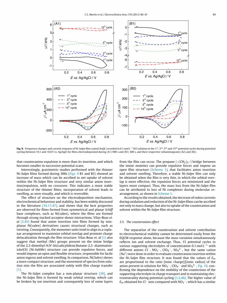
C.S. Martin et al. / Electrochimica Acta 178 (2015) 80–91 89
F ed inc 00 s a
tb
Niwtss
eiabtaptndsoiwaat[
tb
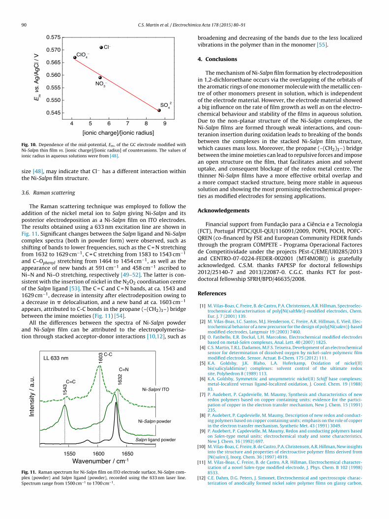
ig. 9. Frequency changes and current response of Ni-Salpn film coated AuQC recordycling between +0.1 and +0.8 V vs. Ag/AgCl for films electrodeposited during (A1) 9
hat counteranion expulsion is more than its insertion, and whichecomes smaller in successive potential scans.
Interestingly, gravimetric studies performed with the thinneri-Salpn films formed during 300s (Figs. 9 B1 and B2) showed an
ncrease of mass which can be ascribed to net uptake of solventithin the Ni-Salpn film structure and very similar anion inser-
ion/expulsion, with no crossover. This indicates a more stabletructure of the thinner films; incorporation of solvent leads towelling, as seen visually, and which is reversible.
The effect of structure on the electrodeposition mechanism,lectrochemical behaviour and stability, has been widely discussedn the literature [16,17,47], and shows that the best propertiesre observed for films formed from symmetrical and planar Schiffase complexes, such as Ni(salen), where the films are formedhrough strong stacked acceptor-donor interactions. Vilas-Boas et.l [2,45] found that anion insertion into films formed by non-lanar Ni(salen) derivatives causes structural changes, such aswisting. Consequently, the monomer units tend to align in a copla-ar arrangement to maximize orbital overlap and promote chargeelocalization through the film structure. Vilas-Boas et. al [1] alsouggest that methyl (Me) groups present on the imine bridgef the 2,3-dimethyl-N,N’-bis(salicylidene)butane-2,3- diaminaton-ckel(II) (Ni-SaltMe) structure can provide repulsive forces, and
ould impose an open and flexible structure, responsible for facilenion ingress and solvent swelling. In comparison, Ni(Salen) shows
more compact structure, and the movement of species from solu-ion into the film are associated solely with film charge transfer
1].The Ni-Salpn complex has a non-planar structure [30], andhe Ni-Salpn film is formed by weak orbital overlap, which cane broken by ion insertion and consequently loss of some layers
0.1 mol L−1 KCl solution in the 1st, 3rd, 5th and 15th potential cycles during potentialnd (B1) 300 s, and their respective voltammograms (A2) and (B2).
from the film can occur. The propane (–(CH2)3–) bridge betweenthe imine moieties can provide repulsive forces and impose anopen film structure (Scheme 1), that facilitates anion insertionand solvent swelling. Therefore, a stable Ni-Salpn film can onlybe obtained when the film is very thin, in which the orbital over-lap is more effective, the repulsion forces are minimized and thelayers more compact. Thus, the mass loss from the Ni-Salpn filmcan be attributed to loss of Ni complexes during molecular re-arrangement, as shown in Scheme 1.
According to the results obtained, the decrease of redox currentsduring oxidation and reduction of the Ni-Salpn films can be ascribednot only to mass change, but also to uptake of the counteranion andsolvent within the Ni-Salpn film structure.
3.5. The counteranion effect
The separation of the counteranion and solvent contributionto electrochemical stability cannot be determined easily from theEQCM response alone, because the mass variation simultaneouslyreflects ion and solvent exchange. Thus, 15 potential cycles invarious supporting electrolytes of concentration 0.1 mol L−1 withdifferent anions Cl−, NO3
−, ClO4−, SO4
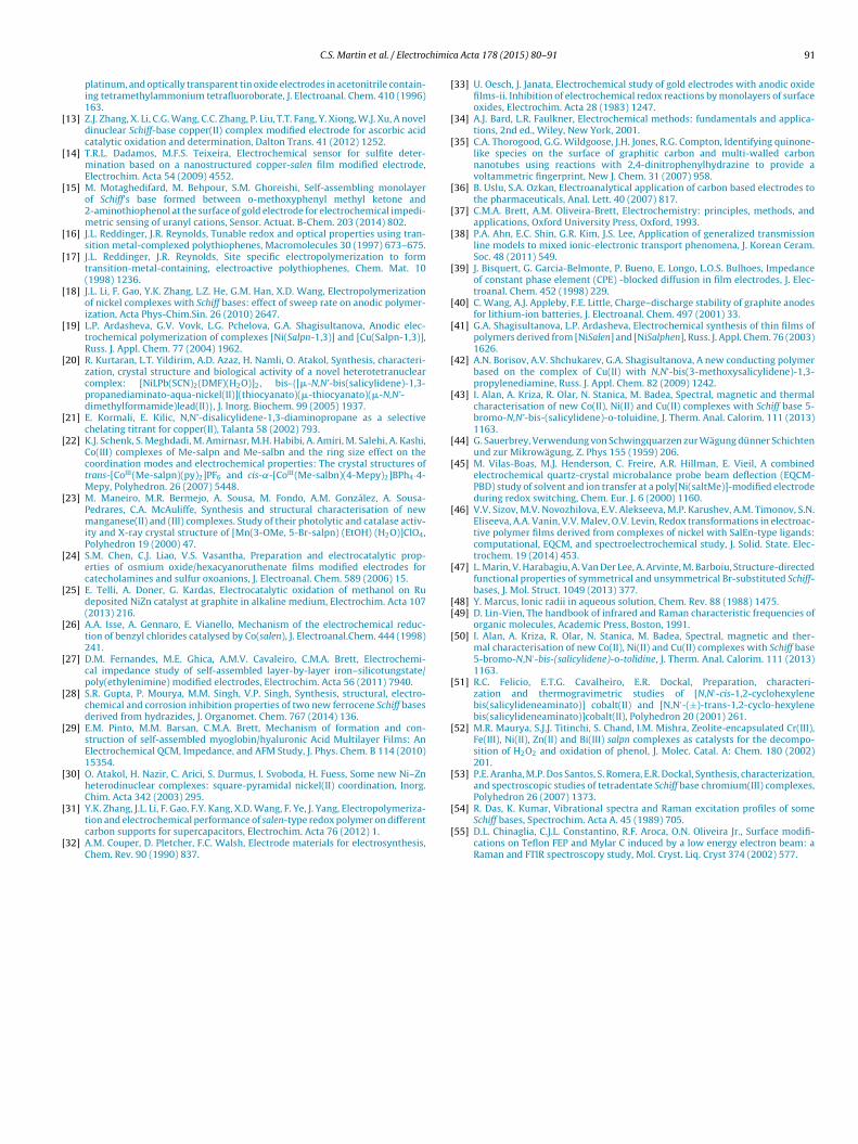
2−, but the same cation(Na+) were done in order to evaluate counteranion insertion withinthe Ni-Salpn film structure. It was found that the values of Em
are proportional to the ratio [ionic charge]/[ionic radius] of theanion present in solution for NO3
−, ClO4− and SO4
2−, Fig. 10, con-
firming the dependence on the mobility of the counterions of thesupporting electrolyte in charge transport and in maintaining elec-troneutrality during potential cycling [1,2,46]. The higher value ofEm obtained for Cl− ions compared with NO3−, which has a similar
90 C.S. Martin et al. / Electrochimic
FNi
st
3
apTFcsfaaNso1aab
at
FpS
ig. 10. Dependence of the mid-potential, Em, of the GC electrode modified withi-Salpn thin film vs. [ionic charge]/[ionic radius] of counteranions. The values of
onic radius in aqueous solutions were from [48].
ize [48], may indicate that Cl− has a different interaction withinhe Ni-Salpn film structure.
.6. Raman scattering
The Raman scattering technique was employed to follow theddition of the nickel metal ion to Salpn giving Ni-Salpn and itsosterior electrodeposition as a Ni-Salpn film on ITO electrodes.he results obtained using a 633 nm excitation line are shown inig. 11. Significant changes between the Salpn ligand and Ni-Salpnomplex spectra (both in powder form) were observed, such ashifting of bands to lower frequencies, such as the C = N stretchingrom 1632 to 1629 cm−1, C = C stretching from 1583 to 1543 cm−1
nd C–Ophenyl stretching from 1464 to 1454 cm−1, as well as theppearance of new bands at 591 cm−1 and 458 cm−1 ascribed toi–N and Ni–O stretching, respectively [49–52]. The latter is con-
istent with the insertion of nickel in the N2O2 coordination centref the Salpn ligand [53]. The C = C and C = N bands, at ca. 1543 and629 cm−1, decrease in intensity after electrodeposition owing to
decrease in � delocalisation, and a new band at ca. 1603 cm−1
ppears, attributed to C-C bonds in the propane (–(CH2)3–) bridge
etween the imine moieties (Fig. 11) [54].All the differences between the spectra of Ni-Salpn powdernd Ni-Salpn film can be attributed to the electropolymerisa-ion through stacked acceptor-donor interactions [10,12], such as
ig. 11. Raman spectrum for Ni-Salpn film on ITO electrode surface, Ni-Salpn com-lex (powder) and Salpn ligand (powder), recorded using the 633 nm laser line.pectrum range from 1500 cm−1 to 1700 cm−1.
[
[
[
a Acta 178 (2015) 80–91
broadening and decreasing of the bands due to the less localizedvibrations in the polymer than in the monomer [55].
4. Conclusions
The mechanism of Ni-Salpn film formation by electrodepositionin 1,2-dichloroethane occurs via the overlapping of the orbitals ofthe aromatic rings of one monomer molecule with the metallic cen-tre of other monomers present in solution, which is independentof the electrode material. However, the electrode material showeda big influence on the rate of film growth as well as on the electro-chemical behaviour and stability of the films in aqueous solution.Due to the non-planar structure of the Ni-Salpn complexes, theNi-Salpn films are formed through weak interactions, and coun-teranion insertion during oxidation leads to breaking of the bondsbetween the complexes in the stacked Ni-Salpn film structure,which causes mass loss. Moreover, the propane (–(CH2)3–) bridgebetween the imine moieties can lead to repulsive forces and imposean open structure on the film, that facilitates anion and solventuptake, and consequent blockage of the redox metal centre. Thethinner Ni-Salpn films have a more effective orbital overlap anda more compact stacked structure, being more stable in aqueoussolution and showing the most promising electrochemical proper-ties as modified electrodes for sensing applications.
Acknowledgements
Financial support from Fundac ão para a Ciência e a Tecnologia(FCT), Portugal PTDC/QUI-QUI/116091/2009, POPH, POCH, POFC-QREN (co-financed by FSE and European Community FEDER fundsthrough the program COMPETE - Programa Operacional Factoresde Competitividade under the projects PEst-C/EME/UI0285/2013and CENTRO-07-0224-FEDER-002001 (MT4MOBI)) is gratefullyacknowledged. C.S.M. thanks FAPESP for doctoral fellowships2012/25140-7 and 2013/22087-0. C.G.C. thanks FCT for post-doctoral fellowship SFRH/BPD/46635/2008.
References
[1] M. Vilas-Boas, C. Freire, B. de Castro, P.A. Christensen, A.R. Hillman, Spectroelec-trochemical characterisation of poly[Ni(saltMe)]-modified electrodes, Chem.Eur. J. 7 (2001) 139.
[2] M. Vilas-Boas, I.C. Santos, M.J. Henderson, C. Freire, A.R. Hillman, E. Vieil, Elec-trochemical behavior of a new precursor for the design of poly[Ni(salen)]-basedmodified electrodes, Langmuir 19 (2003) 7460.
[3] O. Fatibello, E.R. Dockal, L.H. Marcolino, Electrochemical modified electrodesbased on metal-Salen complexes, Anal. Lett. 40 (2007) 1825.
[4] C.S. Martin, T.R.L. Dadamos, M.F.S. Teixeira, Development of an electrochemicalsensor for determination of dissolved oxygen by nickel–salen polymeric filmmodified electrode, Sensor. Actuat. B-Chem. 175 (2012) 111.
[5] K.A. Goldsby, J.K. Blaho, L.A. Hoferkamp, Oxidation of nickel(II)bis(salicylaldimine) complexes: solvent control of the ultimate redoxsite, Polyhedron 8 (1989) 113.
[6] K.A. Goldsby, Symmetric and unsymmetric nickel(II) Schiff base complexes;metal-localized versus ligand-localized oxidation, J. Coord. Chem. 19 (1988)83.
[7] P. Audebert, P. Capdevielle, M. Maumy, Synthesis and characteristics of newredox polymers based on copper containing units; evidence for the partici-pation of copper in the electron transfer mechanism, New J. Chem. 15 (1991)235.
[8] P. Audebert, P. Capdevielle, M. Maumy, Description of new redox and conduct-ing polymers based on copper containing units; emphasis on the role of copperin the electron transfer mechanism, Synthetic Met. 43 (1991) 3049.
[9] P. Audebert, P. Capdevielle, M. Maumy, Redox and conducting polymers basedon Salen-type metal units; electrochemical study and some characteristics,New J. Chem. 16 (1992) 697.
10] M. Vilas-Boas, C. Freire, B. de Castro, P.A. Christensen, A.R. Hillman, New insightsinto the structure and properties of electroactive polymer films derived from[Ni(salen)], Inorg. Chem. 36 (1997) 4919.
11] M. Vilas-Boas, C. Freire, B. de Castro, A.R. Hillman, Electrochemical character-ization of a novel Salen-type modified electrode, J. Phys. Chem. B 102 (1998)8533.
12] C.E. Dahm, D.G. Peters, J. Simonet, Electrochemical and spectroscopic charac-terization of anodically formed nickel salen polymer films on glassy carbon,
himic
[
[
[
[
[
[
[
[
[
[
[
[
[
[
[
[
[
[
[
[
[
[
[
[
[
[
[
[
[
[
[
[
[
[
[
[[
[
[
[
[
C.S. Martin et al. / Electroc
platinum, and optically transparent tin oxide electrodes in acetonitrile contain-ing tetramethylammonium tetrafluoroborate, J. Electroanal. Chem. 410 (1996)163.
13] Z.J. Zhang, X. Li, C.G. Wang, C.C. Zhang, P. Liu, T.T. Fang, Y. Xiong, W.J. Xu, A noveldinuclear Schiff-base copper(II) complex modified electrode for ascorbic acidcatalytic oxidation and determination, Dalton Trans. 41 (2012) 1252.
14] T.R.L. Dadamos, M.F.S. Teixeira, Electrochemical sensor for sulfite deter-mination based on a nanostructured copper-salen film modified electrode,Electrochim. Acta 54 (2009) 4552.
15] M. Motaghedifard, M. Behpour, S.M. Ghoreishi, Self-assembling monolayerof Schiff’s base formed between o-methoxyphenyl methyl ketone and2-aminothiophenol at the surface of gold electrode for electrochemical impedi-metric sensing of uranyl cations, Sensor. Actuat. B-Chem. 203 (2014) 802.
16] J.L. Reddinger, J.R. Reynolds, Tunable redox and optical properties using tran-sition metal-complexed polythiophenes, Macromolecules 30 (1997) 673–675.
17] J.L. Reddinger, J.R. Reynolds, Site specific electropolymerization to formtransition-metal-containing, electroactive polythiophenes, Chem. Mat. 10(1998) 1236.
18] J.L. Li, F. Gao, Y.K. Zhang, L.Z. He, G.M. Han, X.D. Wang, Electropolymerizationof nickel complexes with Schiff bases: effect of sweep rate on anodic polymer-ization, Acta Phys-Chim.Sin. 26 (2010) 2647.
19] L.P. Ardasheva, G.V. Vovk, L.G. Pchelova, G.A. Shagisultanova, Anodic elec-trochemical polymerization of complexes [Ni(Salpn-1,3)] and [Cu(Salpn-1,3)],Russ. J. Appl. Chem. 77 (2004) 1962.
20] R. Kurtaran, L.T. Yildirim, A.D. Azaz, H. Namli, O. Atakol, Synthesis, characteri-zation, crystal structure and biological activity of a novel heterotetranuclearcomplex: [NiLPb(SCN)2(DMF)(H2O)]2, bis-{[�-N,N’-bis(salicylidene)-1,3-propanediaminato-aqua-nickel(II)](thiocyanato)(�-thiocyanato)(�-N,N’-dimethylformamide)lead(II)}, J. Inorg. Biochem. 99 (2005) 1937.
21] E. Kormali, E. Kilic, N,N’-disalicylidene-1,3-diaminopropane as a selectivechelating titrant for copper(II), Talanta 58 (2002) 793.
22] K.J. Schenk, S. Meghdadi, M. Amirnasr, M.H. Habibi, A. Amiri, M. Salehi, A. Kashi,Co(III) complexes of Me-salpn and Me-salbn and the ring size effect on thecoordination modes and electrochemical properties: The crystal structures oftrans-[CoIII(Me-salpn)(py)2]PF6 and cis-˛-[CoIII(Me-salbn)(4-Mepy)2]BPh4·4-Mepy, Polyhedron. 26 (2007) 5448.
23] M. Maneiro, M.R. Bermejo, A. Sousa, M. Fondo, A.M. González, A. Sousa-Pedrares, C.A. McAuliffe, Synthesis and structural characterisation of newmanganese(II) and (III) complexes. Study of their photolytic and catalase activ-ity and X-ray crystal structure of [Mn(3-OMe, 5-Br-salpn) (EtOH) (H2O)]ClO4,Polyhedron 19 (2000) 47.
24] S.M. Chen, C.J. Liao, V.S. Vasantha, Preparation and electrocatalytic prop-erties of osmium oxide/hexacyanoruthenate films modified electrodes forcatecholamines and sulfur oxoanions, J. Electroanal. Chem. 589 (2006) 15.
25] E. Telli, A. Doner, G. Kardas, Electrocatalytic oxidation of methanol on Rudeposited NiZn catalyst at graphite in alkaline medium, Electrochim. Acta 107(2013) 216.
26] A.A. Isse, A. Gennaro, E. Vianello, Mechanism of the electrochemical reduc-tion of benzyl chlorides catalysed by Co(salen), J. Electroanal.Chem. 444 (1998)241.
27] D.M. Fernandes, M.E. Ghica, A.M.V. Cavaleiro, C.M.A. Brett, Electrochemi-cal impedance study of self-assembled layer-by-layer iron–silicotungstate/poly(ethylenimine) modified electrodes, Electrochim. Acta 56 (2011) 7940.
28] S.R. Gupta, P. Mourya, M.M. Singh, V.P. Singh, Synthesis, structural, electro-chemical and corrosion inhibition properties of two new ferrocene Schiff basesderived from hydrazides, J. Organomet. Chem. 767 (2014) 136.
29] E.M. Pinto, M.M. Barsan, C.M.A. Brett, Mechanism of formation and con-struction of self-assembled myoglobin/hyaluronic Acid Multilayer Films: AnElectrochemical QCM, Impedance, and AFM Study, J. Phys. Chem. B 114 (2010)15354.
30] O. Atakol, H. Nazir, C. Arici, S. Durmus, I. Svoboda, H. Fuess, Some new Ni–Znheterodinuclear complexes: square-pyramidal nickel(II) coordination, Inorg.Chim. Acta 342 (2003) 295.
31] Y.K. Zhang, J.L. Li, F. Gao, F.Y. Kang, X.D. Wang, F. Ye, J. Yang, Electropolymeriza-tion and electrochemical performance of salen-type redox polymer on differentcarbon supports for supercapacitors, Electrochim. Acta 76 (2012) 1.
32] A.M. Couper, D. Pletcher, F.C. Walsh, Electrode materials for electrosynthesis,Chem. Rev. 90 (1990) 837.
[
[
a Acta 178 (2015) 80–91 91
33] U. Oesch, J. Janata, Electrochemical study of gold electrodes with anodic oxidefilms-ii. Inhibition of electrochemical redox reactions by monolayers of surfaceoxides, Electrochim. Acta 28 (1983) 1247.
34] A.J. Bard, L.R. Faulkner, Electrochemical methods: fundamentals and applica-tions, 2nd ed., Wiley, New York, 2001.
35] C.A. Thorogood, G.G. Wildgoose, J.H. Jones, R.G. Compton, Identifying quinone-like species on the surface of graphitic carbon and multi-walled carbonnanotubes using reactions with 2,4-dinitrophenylhydrazine to provide avoltammetric fingerprint, New J. Chem. 31 (2007) 958.
36] B. Uslu, S.A. Ozkan, Electroanalytical application of carbon based electrodes tothe pharmaceuticals, Anal. Lett. 40 (2007) 817.
37] C.M.A. Brett, A.M. Oliveira-Brett, Electrochemistry: principles, methods, andapplications, Oxford University Press, Oxford, 1993.
38] P.A. Ahn, E.C. Shin, G.R. Kim, J.S. Lee, Application of generalized transmissionline models to mixed ionic-electronic transport phenomena, J. Korean Ceram.Soc. 48 (2011) 549.
39] J. Bisquert, G. Garcia-Belmonte, P. Bueno, E. Longo, L.O.S. Bulhoes, Impedanceof constant phase element (CPE) -blocked diffusion in film electrodes, J. Elec-troanal. Chem. 452 (1998) 229.
40] C. Wang, A.J. Appleby, F.E. Little, Charge–discharge stability of graphite anodesfor lithium-ion batteries, J. Electroanal. Chem. 497 (2001) 33.
41] G.A. Shagisultanova, L.P. Ardasheva, Electrochemical synthesis of thin films ofpolymers derived from [NiSalen] and [NiSalphen], Russ. J. Appl. Chem. 76 (2003)1626.
42] A.N. Borisov, A.V. Shchukarev, G.A. Shagisultanova, A new conducting polymerbased on the complex of Cu(II) with N,N’-bis(3-methoxysalicylidene)-1,3-propylenediamine, Russ. J. Appl. Chem. 82 (2009) 1242.
43] I. Alan, A. Kriza, R. Olar, N. Stanica, M. Badea, Spectral, magnetic and thermalcharacterisation of new Co(II), Ni(II) and Cu(II) complexes with Schiff base 5-bromo-N,N’-bis-(salicylidene)-o-toluidine, J. Therm. Anal. Calorim. 111 (2013)1163.
44] G. Sauerbrey, Verwendung von Schwingquarzen zur Wägung dünner Schichtenund zur Mikrowägung, Z. Phys 155 (1959) 206.
45] M. Vilas-Boas, M.J. Henderson, C. Freire, A.R. Hillman, E. Vieil, A combinedelectrochemical quartz-crystal microbalance probe beam deflection (EQCM-PBD) study of solvent and ion transfer at a poly[Ni(saltMe)]-modified electrodeduring redox switching, Chem. Eur. J. 6 (2000) 1160.
46] V.V. Sizov, M.V. Novozhilova, E.V. Alekseeva, M.P. Karushev, A.M. Timonov, S.N.Eliseeva, A.A. Vanin, V.V. Malev, O.V. Levin, Redox transformations in electroac-tive polymer films derived from complexes of nickel with SalEn-type ligands:computational, EQCM, and spectroelectrochemical study, J. Solid. State. Elec-trochem. 19 (2014) 453.
47] L. Marin, V. Harabagiu, A. Van Der Lee, A. Arvinte, M. Barboiu, Structure-directedfunctional properties of symmetrical and unsymmetrical Br-substituted Schiff-bases, J. Mol. Struct. 1049 (2013) 377.
48] Y. Marcus, Ionic radii in aqueous solution, Chem. Rev. 88 (1988) 1475.49] D. Lin-Vien, The handbook of infrared and Raman characteristic frequencies of
organic molecules, Academic Press, Boston, 1991.50] I. Alan, A. Kriza, R. Olar, N. Stanica, M. Badea, Spectral, magnetic and ther-
mal characterisation of new Co(II), Ni(II) and Cu(II) complexes with Schiff base5-bromo-N,N′-bis-(salicylidene)-o-tolidine, J. Therm. Anal. Calorim. 111 (2013)1163.
51] R.C. Felicio, E.T.G. Cavalheiro, E.R. Dockal, Preparation, characteri-zation and thermogravimetric studies of [N,N′-cis-1,2-cyclohexylenebis(salicylideneaminato)] cobalt(II) and [N,N′-(±)-trans-1,2-cyclo-hexylenebis(salicylideneaminato)]cobalt(II), Polyhedron 20 (2001) 261.
52] M.R. Maurya, S.J.J. Titinchi, S. Chand, I.M. Mishra, Zeolite-encapsulated Cr(III),Fe(III), Ni(II), Zn(II) and Bi(III) salpn complexes as catalysts for the decompo-sition of H2O2 and oxidation of phenol, J. Molec. Catal. A: Chem. 180 (2002)201.
53] P.E. Aranha, M.P. Dos Santos, S. Romera, E.R. Dockal, Synthesis, characterization,and spectroscopic studies of tetradentate Schiff base chromium(III) complexes,Polyhedron 26 (2007) 1373.
54] R. Das, K. Kumar, Vibrational spectra and Raman excitation profiles of someSchiff bases, Spectrochim. Acta A. 45 (1989) 705.
55] D.L. Chinaglia, C.J.L. Constantino, R.F. Aroca, O.N. Oliveira Jr., Surface modifi-cations on Teflon FEP and Mylar C induced by a low energy electron beam: aRaman and FTIR spectroscopy study, Mol. Cryst. Liq. Cryst 374 (2002) 577.


![Electrodeposition of Zn-Mn alloys from recycling battery leach … · 2014. 5. 20. · recovery by electrodeposition [1–4] is currently being studied in our laboratory [5]. Electrodeposition](https://img.pdfslide.us/doc/110x75/6112e3e4b1654c15ca54266d/electrodeposition-of-zn-mn-alloys-from-recycling-battery-leach-2014-5-20-recovery.jpg)