Embed Size (px)
Citation preview
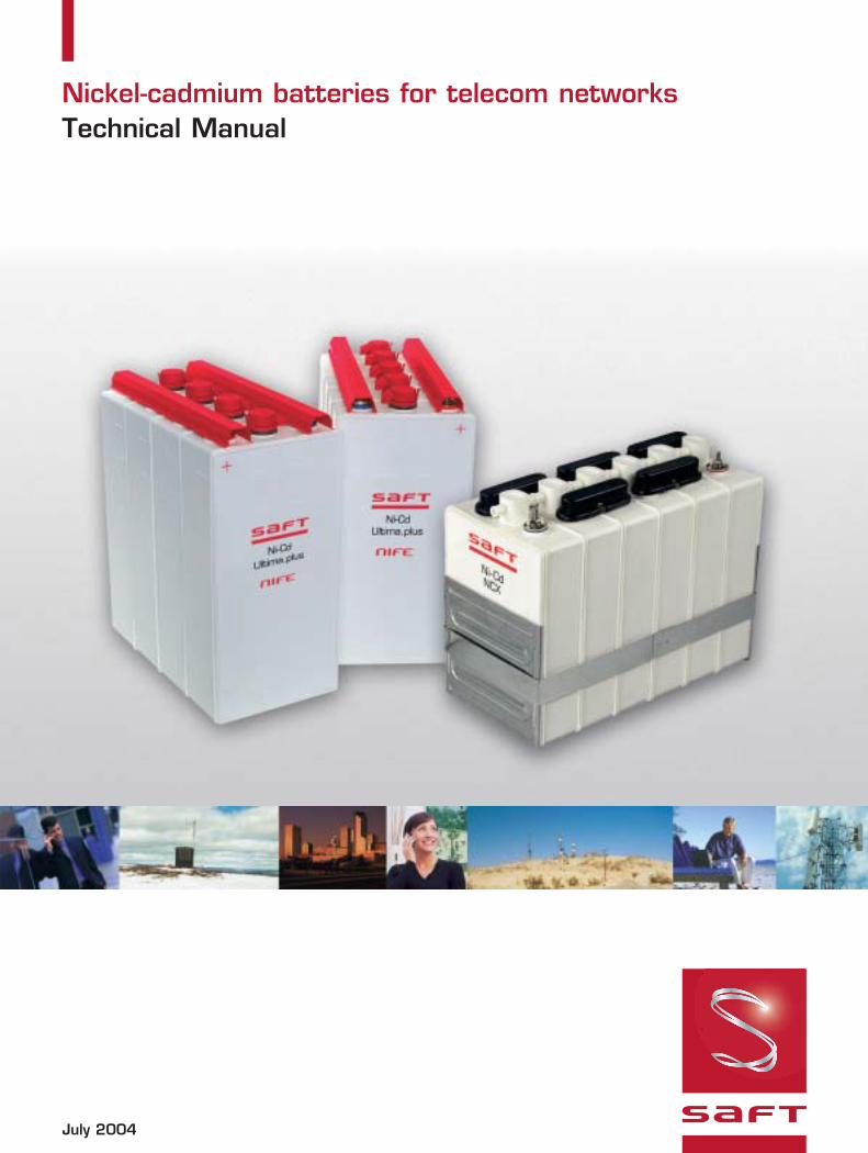
Nickel-cadmium batteries for telecom networksTechnical Manual
July 2004
1. Safety and warranty statement . . . . . . . . . . . . . . . . . . . . . . . . . 3
2. Introduction . . . . . . . . . . . . . . . . . . . . . . . . . . . . . . . . . . . . . 4
3. History . . . . . . . . . . . . . . . . . . . . . . . . . . . . . . . . . . . . . 5
4. Electrochemistry of nickel-cadmium batteries . . . . . . . . . . . . . . . . 6
5. Types and construction . . . . . . . . . . . . . . . . . . . . . . . . . . . . . . 75.1 Overview . . . . . . . . . . . . . . . . . . . . . . . . . . . . . . 75.2 Pocket plate batteries . . . . . . . . . . . . . . . . . . . . . . 75.3 Sintered plate batteries . . . . . . . . . . . . . . . . . . . . . 95.4 Plastic bonded electrodes . . . . . . . . . . . . . . . . . . . 95.5 S/PBE batteries . . . . . . . . . . . . . . . . . . . . . . . . . 105.6 Fiber plate batteries . . . . . . . . . . . . . . . . . . . . . . . 10
6. Nickel-cadmium telecom batteries . . . . . . . . . . . . . . . . . . . . . . . 11
7. Features and benefits . . . . . . . . . . . . . . . . . . . . . . . . . . . . . . . 137.1 Long life . . . . . . . . . . . . . . . . . . . . . . . . . . . . . . . 137.2 Reliability . . . . . . . . . . . . . . . . . . . . . . . . . . . . . . 137.3 Very low maintenance . . . . . . . . . . . . . . . . . . . . . . 137.4 Permanent mechanical integrity . . . . . . . . . . . . . . . 137.5 Resistant to electrical abuse . . . . . . . . . . . . . . . . . 137.6 Wide temperature range . . . . . . . . . . . . . . . . . . . . 147.7 Safe recycling . . . . . . . . . . . . . . . . . . . . . . . . . . . 147.8 Low life cycle cost . . . . . . . . . . . . . . . . . . . . . . . . 147.9 Special features . . . . . . . . . . . . . . . . . . . . . . . . . 15
8. Telecom network applications . . . . . . . . . . . . . . . . . . . . . . . . . . 188.1 Remote cabinets in access networks . . . . . . . . . . . . 188.2 CEVs, huts and shelters . . . . . . . . . . . . . . . . . . . . 208.3 Customer premises . . . . . . . . . . . . . . . . . . . . . . . 208.4 Central offices . . . . . . . . . . . . . . . . . . . . . . . . . . . 208.5 Cellular systems . . . . . . . . . . . . . . . . . . . . . . . . . 218.6 Broadband transmission circuits . . . . . . . . . . . . . . . 218.7 Cable TV . . . . . . . . . . . . . . . . . . . . . . . . . . . . . . 22
9. Operating features . . . . . . . . . . . . . . . . . . . . . . . . . . . . . . . . . 239.1 Capacity . . . . . . . . . . . . . . . . . . . . . . . . . . . . . . 239.2 Current rates . . . . . . . . . . . . . . . . . . . . . . . . . . . 239.3 Cell voltage . . . . . . . . . . . . . . . . . . . . . . . . . . . . 249.4 Internal resistance . . . . . . . . . . . . . . . . . . . . . . . 259.5 Effect of temperature on performance . . . . . . . . . . 259.6 Effect of temperature on lifetime . . . . . . . . . . . . . . 269.7 Short circuit values . . . . . . . . . . . . . . . . . . . . . . . 279.8 Self discharge . . . . . . . . . . . . . . . . . . . . . . . . . . 279.9 Cycling . . . . . . . . . . . . . . . . . . . . . . . . . . . . . . . 289.10 Water consumption . . . . . . . . . . . . . . . . . . . . . . 299.11 Gas evolution . . . . . . . . . . . . . . . . . . . . . . . . . . . 29
2
Contents
10. Battery charging . . . . . . . . . . . . . . . . . . . . . . . . . . . . . . . . . 3010.1 Constant voltage charging . . . . . . . . . . . . . . . . . . . 3010.2 Constant current charging . . . . . . . . . . . . . . . . . . . 3110.3 Charge acceptance and efficiency . . . . . . . . . . . . . . 3210.4 Temperature effects . . . . . . . . . . . . . . . . . . . . . . . 3310.5 Commissioning charge . . . . . . . . . . . . . . . . . . . . . . 33
11. Special operating features . . . . . . . . . . . . . . . . . . . . . . . . . . . 3411.1 Electrical abuse . . . . . . . . . . . . . . . . . . . . . . . . . . 3411.2 Mechanical abuse . . . . . . . . . . . . . . . . . . . . . . . . . 3511.3 Corrosion . . . . . . . . . . . . . . . . . . . . . . . . . . . . . . 35
12. Battery sizing principles . . . . . . . . . . . . . . . . . . . . . . . . . . . . . 3612.1 NCX and Ultima.plus sizing . . . . . . . . . . . . . . . . . . . 3612.2 Sunica.plus sizing . . . . . . . . . . . . . . . . . . . . . . . . . 3612.3 Battery sizing for engine
starting and cranking applications . . . . . . . . . . . . . . 36
13. Installation and operation . . . . . . . . . . . . . . . . . . . . . . . . . . . . 3713.1 Safety . . . . . . . . . . . . . . . . . . . . . . . . . . . . . . . . 3713.2 Transportation and storage . . . . . . . . . . . . . . . . . . . 3713.3 Installation . . . . . . . . . . . . . . . . . . . . . . . . . . . . . . 3713.4 Maintenance . . . . . . . . . . . . . . . . . . . . . . . . . . . . 37
14. Disposal and recycling . . . . . . . . . . . . . . . . . . . . . . . . . . . . . . 38
15. Abbreviations and acronyms . . . . . . . . . . . . . . . . . . . . . . . . . . 39
Contents
3
4
In addition, studying this Technicalmanual will give you a betterunderstanding of Ni-Cd batteriesused in the telecom industry andwill help you to choose the rightNi-Cd battery for your applicationand make you more familiar withthe behavior of Ni-Cd batteries andtheir operating characteristics. If you have questions about any ofthese documents or their content,contact your nearest Saftrepresentative. Several contactpoints are detailed on the backcover of this document.
Non-compliance withinformation and instructions
contained in the above mentioneddocuments, may lead to poorbattery performance, reducedbattery life, higher operatingcosts, risk of damage to thebattery and in extreme cases, riskof damage to the battery’senvironment and risk of personalinjury. Saft will in such casesreserve the right to void anywarranty or liability.
Spent batteries must be disposedof in accordance with national andlocal government regulations.
In most countries, it is theresponsibility of the batteryoperator or owner to make suresuch regulations are adhered to.
Saft has established approvedfacilities for battery collection andrecycling. Consult the Installationand Operating Instruction orcontact your nearest Saftrepresentative for advice.
In conclusion: to get the mostout of your Ni-Cd batteries atthe lowest cost and withoutproblems, follow the instructionsclosely.
Spending a little time learningmore about Ni-Cd batteries andtheir behavior will help you tomake the right battery selectionand be a better operator and willalso make the task moreinteresting. Do not be afraid toask questions. Saft has a teamof dedicated career batteryprofessionals at your disposal.
1. Safety and warranty statement
Saft nickel-cadmium batteries areinherently safe to handle andoperate. As long as Saft’sinformation and instructions arefollowed, they will last longer andfunction more reliably than otherstorage batteries. Furthermore, allchemicals and active materials willremain safely contained inside thebatteries during their entire life,from production to reclamation.The physical integrity of Saft nickel-cadmium batteries will notdeteriorate during the life of thebatteries. All spent nickel-cadmiumbatteries will be recycled.
To obtain optimum performanceand operating life, to ensure safehandling and operation and toensure that Saft’s warranty willremain in force, Saft’s informationand instructions must be followed.Any person responsible forhandling, installing and operatingSaft batteries must study andunderstand the following twodocuments:
• MSDS (Material Safety DataSheet)
• Installation and OperatingInstructions for the relevanttype of Ni-Cd battery.
This document is meant as aguide to the selection and use ofstationary Ni-Cd batteries intelecommunication applications.The batteries discussed here areall of a flooded construction butmay employ different types ofplates and maintenance reductiontechniques. Small sealed Ni-Cdbatteries as used in cellulartelephones and other portableapplications will not be covered inthis document. Informationprovided here on battery features,charging requirements andperformance must not be appliedto portable sealed Ni-Cd batteriesas their characteristics are quitedifferent from the batteriesdiscussed in this manual. In thismanual “Ni-Cd batteries” will meanflooded, stationary nickel-cadmiumbatteries, also often referred toas industrial nickel-cadmiumbatteries.
Most operators of telecomfacilities are familiar with lead-acidbatteries. Specifications, designsand operating parameters ofother telecom power equipmentare, to a large extent, based onthe operating requirements oflead-acid batteries. As Ni-Cdbatteries represent a completelydifferent electro-chemistry, thismanual will therefore frequentlydraw attention to and discuss thedifference between these twobattery systems.
Stationary Ni-Cd batteries haveover the years been used invarious telecom applications. With higher purchase prices thanfor lead-acid batteries, there hadto be good reasons for payingmore up front for the Ni-Cdbatteries. In general, the mainreasons were a lower overalloperating cost and significantlyhigher reliability.
Ni-Cd batteries have over theyears proven themselves to beexceptionally durable and reliableeven with a minimum ofmaintenance and under severeoperating conditions where otherbatteries fail prematurely.Hence, in such applications Ni-Cd batteries can clearly offerthe lowest possible life cyclecost among comparableindustrial batteries.
This explains why most Ni-Cdtelecom applications can be foundin remote locations, wheremaintenance is irregular or rarelyperformed, where thetemperature is often very high orvery low and where reliability iscritical. This is why Ni-Cd batteriesare found safeguarding power tothe oil and gas productionprocess, navigational aids, solarpowered repeater stations and on
board jet aircraft where electricpower failures cannot be tolerated.
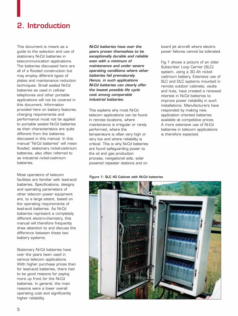
Fig.1 shows a picture of an olderSubscriber Loop Carrier (SLC)system, using a 30 Ah nickel-cadmium battery. Extensive use ofSLC and DLC systems mounted inremote outdoor cabinets, vaultsand huts, have created a renewedinterest in Ni-Cd batteries toimprove power reliability in suchinstallations. Manufacturers haveresponded by making new,application oriented batteriesavailable at competitive prices. A more extensive use of Ni-Cdbatteries in telecom applicationsis therefore expected.
2. Introduction
Figure 1: SLC 40 Cabinet with Ni-Cd batteries
5
6
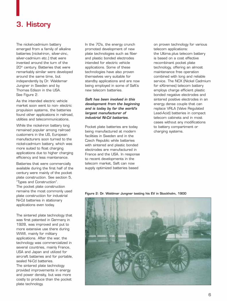
The nickel-cadmium batteryemerged from a family of alkalinebatteries (nickel-iron, silver-zinc,silver-cadmium etc.) that wereinvented around the turn of the20th century. Batteries that wereremarkably similar were developedaround the same time, butindependently by Dr. WaldemarJungner in Sweden and byThomas Edison in the USA. See Figure 2.
As the intended electric vehiclemarket soon went to non- electricpropulsion systems, the batteriesfound other applications in railroad,utilities and telecommunications.
While the nickel-iron battery longremained popular among railroadcustomers in the US, Europeanmanufacturers soon turned to thenickel-cadmium battery, which wasmore suited to float chargingapplications due to higher chargingefficiency and less maintenance.
Batteries that were commerciallyavailable during the first half of thecentury were mainly of the pocketplate construction. See section 5,“Types and Construction”. The pocket plate constructionremains the most commonly usedplate construction for industrial Ni-Cd batteries in stationaryapplications even today.
The sintered plate technology thatwas first patented in Germany in1928, was improved and put tomore extensive use there duringWWII, mainly for militaryapplications. After the war, thetechnology was commercialized inseveral countries, mainly France,USA and Japan and utilized foraircraft batteries and for portable,sealed Ni-Cd batteries. The sintered plate technologyprovided improvements in energyand power density, but was morecostly to produce than the pocketplate technology.
In the 70’s, the energy crunchpromoted development of newplate technologies such as fiberand plastic bonded electrodesintended for electric vehicleapplications. Some of thesetechnologies have also proventhemselves very suitable forstandby applications and are nowbeing employed in some of Saft’snew telecom batteries.
Saft has been involved in thisdevelopment from the beginningand is today by far the world’slargest manufacturer ofindustrial Ni-Cd batteries.
Pocket plate batteries are todaybeing manufactured at modernfacilities in Sweden and in theCzech Republic while batterieswith sintered and plastic bondedelectrodes are manufactured inFrance and the USA. In responseto recent developments in thetelecom market, Saft can nowsupply optimized batteries based
on proven technology for varioustelecom applications: the Ultima.plus telecom battery is based on a cost effectiverecombinant pocket platetechnology, offering an almostmaintenance free operationcombined with long and reliableservice. The NCX (Nickel Cadmiumfor eXtremes) telecom batteryemploys charge efficient plasticbonded negative electrodes andsintered positive electrodes in anenergy dense couple that canreplace VRLA (Valve RegulatedLead-Acid) batteries in compacttelecom cabinets and in mostcases without any modifications to battery compartment orcharging systems.
3. History
Figure 2: Dr. Waldmar Jungner testing his EV in Stockholm, 1900
Thus, through itselectrochemistry, the nickel-cadmium battery has a muchmore stable behavior than thelead-acid battery, giving it alonger life, superiorcharacteristics and much greaterresistance to abusive conditions.
battery support. This can nothappen to a Ni-Cd battery.
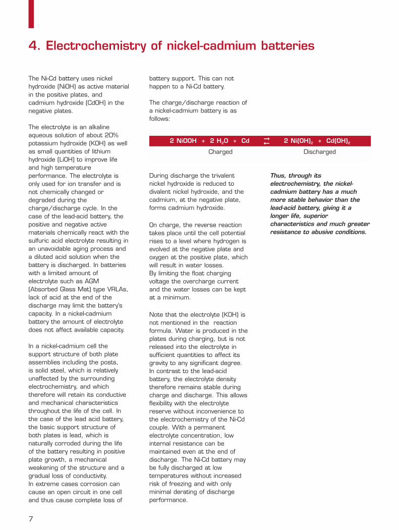
The charge/discharge reaction ofa nickel-cadmium battery is asfollows:
During discharge the trivalentnickel hydroxide is reduced todivalent nickel hydroxide, and thecadmium, at the negative plate,forms cadmium hydroxide.
On charge, the reverse reactiontakes place until the cell potentialrises to a level where hydrogen isevolved at the negative plate andoxygen at the positive plate, whichwill result in water losses. By limiting the float chargingvoltage the overcharge currentand the water losses can be keptat a minimum.
Note that the electrolyte (KOH) isnot mentioned in the reactionformula. Water is produced in theplates during charging, but is notreleased into the electrolyte insufficient quantities to affect itsgravity to any significant degree. In contrast to the lead-acidbattery, the electrolyte densitytherefore remains stable duringcharge and discharge. This allowsflexibility with the electrolytereserve without inconvenience tothe electrochemistry of the Ni-Cdcouple. With a permanentelectrolyte concentration, lowinternal resistance can bemaintained even at the end ofdischarge. The Ni-Cd battery maybe fully discharged at lowtemperatures without increasedrisk of freezing and with onlyminimal derating of dischargeperformance.
The Ni-Cd battery uses nickelhydroxide (NiOH) as active materialin the positive plates, andcadmium hydroxide (CdOH) in thenegative plates.
The electrolyte is an alkalineaqueous solution of about 20%potassium hydroxide (KOH) as wellas small quantities of lithiumhydroxide (LiOH) to improve lifeand high temperatureperformance. The electrolyte isonly used for ion transfer and isnot chemically changed ordegraded during thecharge/discharge cycle. In thecase of the lead-acid battery, thepositive and negative activematerials chemically react with thesulfuric acid electrolyte resulting inan unavoidable aging process anda diluted acid solution when thebattery is discharged. In batterieswith a limited amount ofelectrolyte such as AGM(Absorbed Glass Mat) type VRLAs,lack of acid at the end of thedischarge may limit the battery’scapacity. In a nickel-cadmiumbattery the amount of electrolytedoes not affect available capacity.
In a nickel-cadmium cell thesupport structure of both plateassemblies including the posts, is solid steel, which is relativelyunaffected by the surroundingelectrochemistry, and whichtherefore will retain its conductiveand mechanical characteristicsthroughout the life of the cell. Inthe case of the lead acid battery,the basic support structure ofboth plates is lead, which isnaturally corroded during the lifeof the battery resulting in positiveplate growth, a mechanicalweakening of the structure and agradual loss of conductivity. In extreme cases corrosion cancause an open circuit in one celland thus cause complete loss of
7
4. Electrochemistry of nickel-cadmium batteries
2 NiOOH + 2 H20 + Cd 2 Ni(OH)2 + Cd(OH)2
➞
Charged Discharged
➞
8
5.1. Overview
Nickel-cadmium batteries aregenerally classified with regards totheir plate (electrode) construction.A battery’s plate construction willinfluence its features,characteristics and cost and willtherefore determine its selectionfor certain applications. Furtherenhancements and applicationoptimizations can be achieved byvariations in plate thickness,separator selection, cellconstruction, venting system,control of oxygen recombinationetc. The important point here isthat all Ni-Cd batteries are notcreated equal: what you learnabout one type can notautomatically be applied to another.
The most common types thatcould be considered for telecomapplications are:• Pocket plate (PP)• Sintered plate (SP)• Fiber plate (FP)• Plastic bonded electrode (PBE)
Most batteries use positive andnegative electrodes of the sameconstruction. Take for instance thepocket plate (PP) battery, whichsometimes is also referred to as aP/P (pocket/pocket) type battery.However, it is not uncommon tofind plate combinations of differentconstructions. In particular,batteries with SP positive platesand PBE negatives, referred to asS/PBE batteries, have becomevery popular for certainapplications. Further details aregiven below.
5.2. Pocket plate batteries
PP batteries were developed atthe beginning of the century andhave since then been the mostsuccessful and most commonlyused industrial Ni-Cd batteries forstationary applications. This time-
tested technology has given Ni-Cd batteries their reputation fordurability and reliability. It is notuncommon to find PP batteriesover 30 years old still providingessential power protection. Overthe years, PP batteries have oftenbeen used in extreme conditionsfor telecom applications.
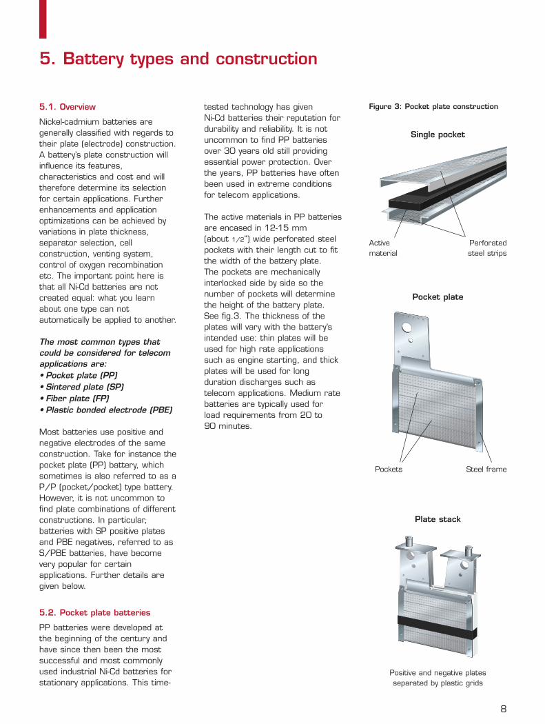
The active materials in PP batteriesare encased in 12-15 mm (about 1/2”) wide perforated steelpockets with their length cut to fitthe width of the battery plate. The pockets are mechanicallyinterlocked side by side so thenumber of pockets will determinethe height of the battery plate.See fig.3. The thickness of theplates will vary with the battery’sintended use: thin plates will beused for high rate applicationssuch as engine starting, and thickplates will be used for longduration discharges such astelecom applications. Medium ratebatteries are typically used forload requirements from 20 to 90 minutes.
5. Battery types and construction
Single pocket
Pocket plate
Plate stack
Active material
Perforated steel strips
Pockets Steel frame
Positive and negative plates separated by plastic grids
Figure 3: Pocket plate construction
9
The steel pockets give the plateshigh and permanent conductivityand also serve as mechanicalbarriers between positive andnegative active materials. No additional separators arerequired apart from plastic pins orsimple plastic grids that are usedfor optimum spacing betweenplates and to provide electricalinsulation. The electrolyte willtherefore circulate freely betweenthe plates and maintain an eventemperature in each cell. Activematerial shedding and separatorproblems are therefore not of anyconcern with PP batteries.
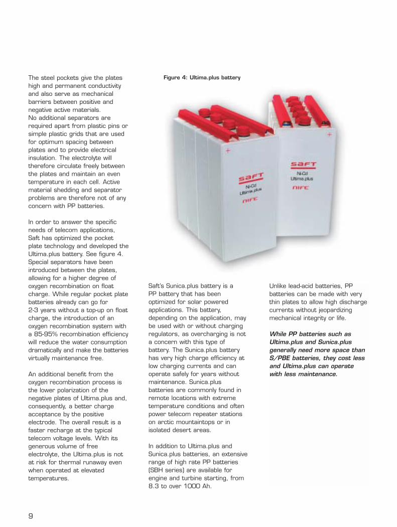
In order to answer the specificneeds of telecom applications,Saft has optimized the pocketplate technology and developed theUltima.plus battery. See figure 4.Special separators have beenintroduced between the plates,allowing for a higher degree ofoxygen recombination on floatcharge. While regular pocket platebatteries already can go for 2-3 years without a top-up on floatcharge, the introduction of anoxygen recombination system witha 85-95% recombination efficiencywill reduce the water consumptiondramatically and make the batteriesvirtually maintenance free.
An additional benefit from theoxygen recombination process isthe lower polarization of thenegative plates of Ultima.plus and,consequently, a better chargeacceptance by the positiveelectrode. The overall result is afaster recharge at the typicaltelecom voltage levels. With itsgenerous volume of freeelectrolyte, the Ultima.plus is notat risk for thermal runaway evenwhen operated at elevatedtemperatures.
Saft’s Sunica.plus battery is aPP battery that has beenoptimized for solar poweredapplications. This battery,depending on the application, maybe used with or without chargingregulators, as overcharging is nota concern with this type ofbattery. The Sunica.plus batteryhas very high charge efficiency atlow charging currents and canoperate safely for years withoutmaintenance. Sunica.plusbatteries are commonly found inremote locations with extremetemperature conditions and oftenpower telecom repeater stationson arctic mountaintops or inisolated desert areas.
In addition to Ultima.plus andSunica.plus batteries, an extensiverange of high rate PP batteries(SBH series) are available forengine and turbine starting, from8.3 to over 1000 Ah.
Figure 4: Ultima.plus battery
Unlike lead-acid batteries, PPbatteries can be made with verythin plates to allow high dischargecurrents without jeopardizingmechanical integrity or life.
While PP batteries such asUltima.plus and Sunica.plusgenerally need more space thanS/PBE batteries, they cost lessand Ultima.plus can operatewith less maintenance.
10
5.3. Sintered plate batteries
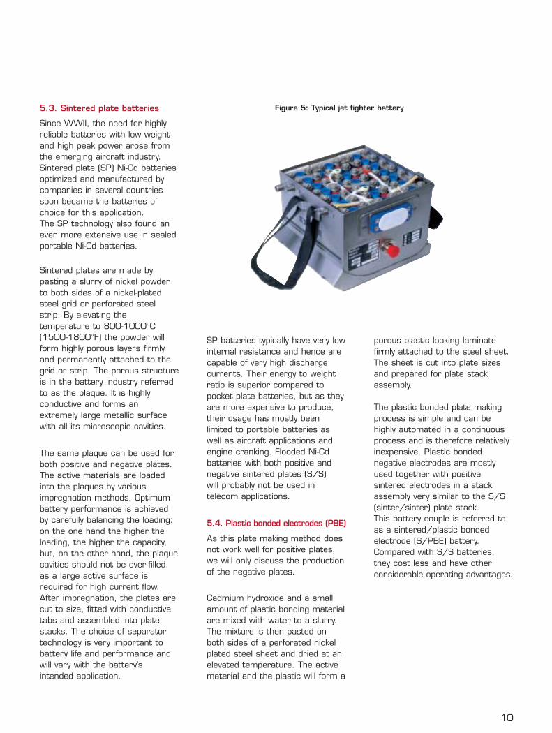
Since WWII, the need for highlyreliable batteries with low weightand high peak power arose fromthe emerging aircraft industry.Sintered plate (SP) Ni-Cd batteriesoptimized and manufactured bycompanies in several countriessoon became the batteries ofchoice for this application. The SP technology also found aneven more extensive use in sealedportable Ni-Cd batteries.
Sintered plates are made bypasting a slurry of nickel powderto both sides of a nickel-platedsteel grid or perforated steelstrip. By elevating thetemperature to 800-1000°C(1500-1800°F) the powder willform highly porous layers firmlyand permanently attached to thegrid or strip. The porous structureis in the battery industry referredto as the plaque. It is highlyconductive and forms anextremely large metallic surfacewith all its microscopic cavities.
The same plaque can be used forboth positive and negative plates.The active materials are loadedinto the plaques by variousimpregnation methods. Optimumbattery performance is achievedby carefully balancing the loading:on the one hand the higher theloading, the higher the capacity,but, on the other hand, the plaquecavities should not be over-filled,as a large active surface isrequired for high current flow.After impregnation, the plates arecut to size, fitted with conductivetabs and assembled into platestacks. The choice of separatortechnology is very important tobattery life and performance andwill vary with the battery’sintended application.
SP batteries typically have very lowinternal resistance and hence arecapable of very high dischargecurrents. Their energy to weightratio is superior compared topocket plate batteries, but as theyare more expensive to produce,their usage has mostly beenlimited to portable batteries aswell as aircraft applications andengine cranking. Flooded Ni-Cdbatteries with both positive andnegative sintered plates (S/S) will probably not be used intelecom applications.
5.4. Plastic bonded electrodes (PBE)
As this plate making method doesnot work well for positive plates,we will only discuss the productionof the negative plates.
Cadmium hydroxide and a smallamount of plastic bonding materialare mixed with water to a slurry.The mixture is then pasted onboth sides of a perforated nickelplated steel sheet and dried at anelevated temperature. The activematerial and the plastic will form a
porous plastic looking laminatefirmly attached to the steel sheet.The sheet is cut into plate sizesand prepared for plate stackassembly.
The plastic bonded plate makingprocess is simple and can behighly automated in a continuousprocess and is therefore relativelyinexpensive. Plastic bondednegative electrodes are mostlyused together with positivesintered electrodes in a stackassembly very similar to the S/S(sinter/sinter) plate stack. This battery couple is referred toas a sintered/plastic bondedelectrode (S/PBE) battery.Compared with S/S batteries, they cost less and have otherconsiderable operating advantages.
Figure 5: Typical jet fighter battery
11
5.5. Sintered/PBE batteries
Similar to the S/S batteries, theS/PBE batteries have high energyand power densities. Furthermore,on float charge their chargingcurrent is much lower andtherefore the water consumptionand the maintenancerequirements have been greatlyreduced. On float charge, theS/PBE battery can operate formore than 10 years without waterreplacement.
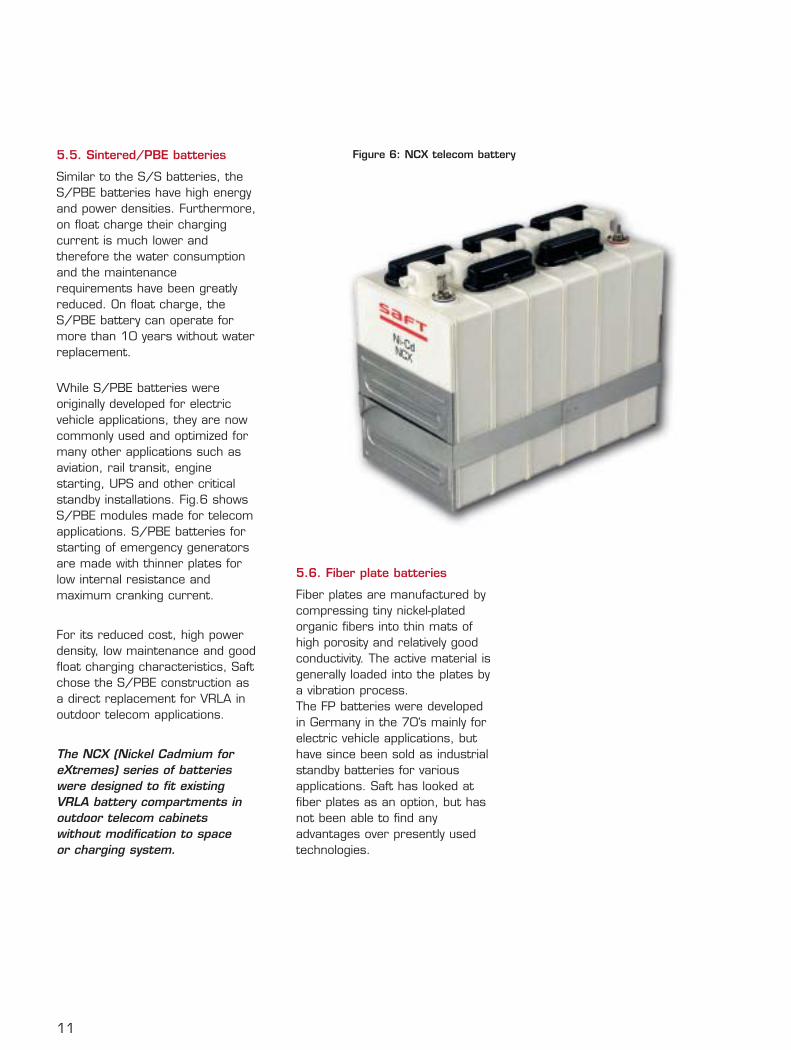
While S/PBE batteries wereoriginally developed for electricvehicle applications, they are nowcommonly used and optimized formany other applications such asaviation, rail transit, enginestarting, UPS and other criticalstandby installations. Fig.6 showsS/PBE modules made for telecomapplications. S/PBE batteries forstarting of emergency generatorsare made with thinner plates forlow internal resistance andmaximum cranking current.
For its reduced cost, high powerdensity, low maintenance and goodfloat charging characteristics, Saftchose the S/PBE construction asa direct replacement for VRLA inoutdoor telecom applications.
The NCX (Nickel Cadmium foreXtremes) series of batterieswere designed to fit existingVRLA battery compartments inoutdoor telecom cabinetswithout modification to space or charging system.
5.6. Fiber plate batteries
Fiber plates are manufactured bycompressing tiny nickel-platedorganic fibers into thin mats ofhigh porosity and relatively goodconductivity. The active material isgenerally loaded into the plates bya vibration process. The FP batteries were developedin Germany in the 70’s mainly forelectric vehicle applications, buthave since been sold as industrialstandby batteries for variousapplications. Saft has looked atfiber plates as an option, but hasnot been able to find anyadvantages over presently usedtechnologies.
Figure 6: NCX telecom battery
12
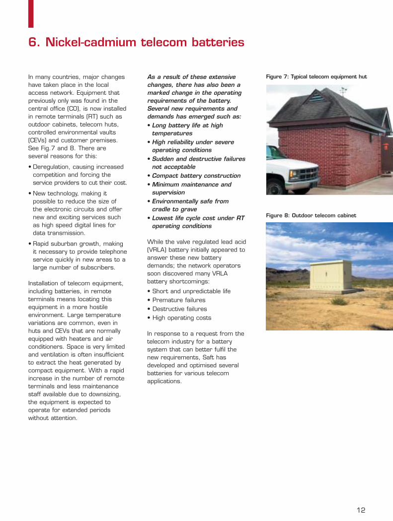
In many countries, major changeshave taken place in the localaccess network. Equipment thatpreviously only was found in thecentral office (CO), is now installedin remote terminals (RT) such asoutdoor cabinets, telecom huts,controlled environmental vaults(CEVs) and customer premises.See Fig.7 and 8. There areseveral reasons for this:
• Deregulation, causing increasedcompetition and forcing theservice providers to cut their cost.
• New technology, making itpossible to reduce the size ofthe electronic circuits and offernew and exciting services suchas high speed digital lines fordata transmission.
• Rapid suburban growth, makingit necessary to provide telephoneservice quickly in new areas to alarge number of subscribers.
Installation of telecom equipment,including batteries, in remoteterminals means locating thisequipment in a more hostileenvironment. Large temperaturevariations are common, even inhuts and CEVs that are normallyequipped with heaters and airconditioners. Space is very limitedand ventilation is often insufficientto extract the heat generated bycompact equipment. With a rapidincrease in the number of remoteterminals and less maintenancestaff available due to downsizing,the equipment is expected tooperate for extended periodswithout attention.
As a result of these extensivechanges, there has also been amarked change in the operatingrequirements of the battery.Several new requirements anddemands has emerged such as:• Long battery life at high
temperatures• High reliability under severe
operating conditions• Sudden and destructive failures
not acceptable• Compact battery construction• Minimum maintenance and
supervision• Environmentally safe from
cradle to grave• Lowest life cycle cost under RT
operating conditions
While the valve regulated lead acid(VRLA) battery initially appeared toanswer these new batterydemands; the network operatorssoon discovered many VRLAbattery shortcomings:
• Short and unpredictable life• Premature failures• Destructive failures• High operating costs
In response to a request from thetelecom industry for a batterysystem that can better fulfil thenew requirements, Saft hasdeveloped and optimised severalbatteries for various telecomapplications.
6. Nickel-cadmium telecom batteries
Figure 7: Typical telecom equipment hut
Figure 8: Outdoor telecom cabinet
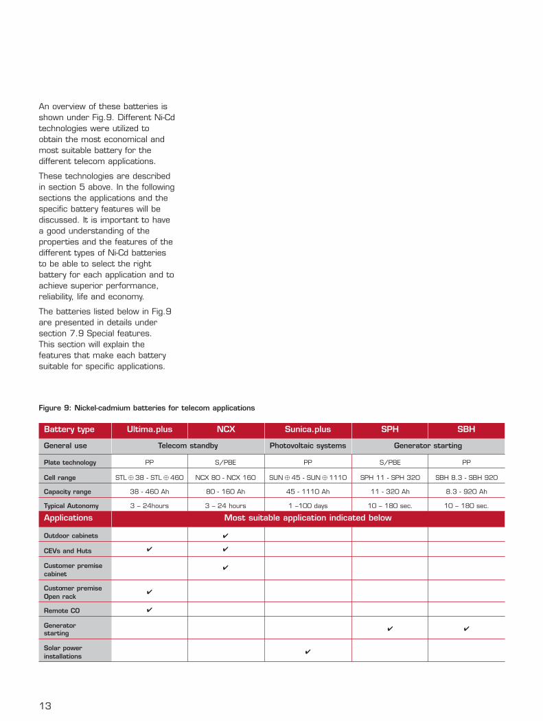
An overview of these batteries isshown under Fig.9. Different Ni-Cdtechnologies were utilized toobtain the most economical andmost suitable battery for thedifferent telecom applications.
These technologies are describedin section 5 above. In the followingsections the applications and thespecific battery features will bediscussed. It is important to havea good understanding of theproperties and the features of thedifferent types of Ni-Cd batteriesto be able to select the rightbattery for each application and toachieve superior performance,reliability, life and economy.
The batteries listed below in Fig.9are presented in details undersection 7.9 Special features. This section will explain thefeatures that make each batterysuitable for specific applications.
13
Figure 9: Nickel-cadmium batteries for telecom applications
Battery type Ultima.plus NCX Sunica.plus SPH SBH
General use Telecom standby Photovoltaic systems Generator starting
Plate technology PP S/PBE PP S/PBE PP
Cell range STL � 38 - STL � 460 NCX 80 - NCX 160 SUN � 45 - SUN � 1110 SPH 11 - SPH 320 SBH 8.3 - SBH 920
Capacity range 38 - 460 Ah 80 - 160 Ah 45 - 1110 Ah 11 - 320 Ah 8.3 - 920 Ah
Typical Autonomy 3 – 24hours 3 – 24 hours 1 –100 days 10 – 180 sec. 10 – 180 sec.
Applications Most suitable application indicated below
Outdoor cabinets ✔
CEVs and Huts ✔ ✔
Customer premise ✔cabinet
Customer premise ✔
Open rack
Remote CO ✔
Generator starting
✔ ✔
Solar power ✔
installations
14
Understanding and appreciatingthe features and benefits of thedifferent types of Ni-Cd batteries isimportant for the battery selectionprocess. Some features arecommon to all Ni-Cd batteries, butas different batteries have beenoptimized for differentapplications, there are significantdifferences. The following featuresare common to all industrial Ni-Cdbatteries:
1. Long life 2. Extremely reliable3. Very low maintenance4. Permanent mechanical integrity5. Resistant to electrical abuse 6. Wide temperature operating
range7. Safe recycling8. Low life cycle cost in suitable
applications
7.1. Long life
Industrial nickel-cadmium batteriescontinue to demonstrate operatinglife in excess of 30 years oncontinuous float charge and inuncontrolled environments. They have for instance been usedfor nearly a century in outdoor railsignal applications where theyhave an excellent track recordprotecting life and valuableproperty.
There are many examples of20 – 30 year old batteriestesting close to 100% capacity.
7.2. Reliability
Nickel-cadmium batteries are thebatteries of choice for theworld’s airlines and rail transitsystems, and are generally usedwhen reliable power is requiredto protect people's lives, valuableproperty or to avoid costlydowntime.
Ni-Cd batteries are reliablebecause of their stable chemistryas described under section 4.They do not suddenly fail and themost common lead acid ailmentssuch as corrosion, plate growthand sulfating are not present inthis battery system.
7.3. Very low maintenance
On float charge, watering isrecommended once a year forregular PP batteries, butUltima.plus and NCX are ultra lowmaintenance batteries that cansafely be left for over 5 years.
Several test batteries have nowbeen in field operation forseveral years at an averagetemperature of +40°C (+104°F).Water consumption has beenclosely monitored and indicationsare that the battery could beleft for over 15 years without atop up.However, watering every 5 yearsis recommended for safetyreasons.
Apart from watering, checkingcharging voltage and visualinspection, no other regularmaintenance is required. See also section 13.
7.4. Permanent mechanicalintegrity
The electrolyte will not react withthe structural parts of a nickel-cadmium cell. On the contrary, it will create a protectiveenvironment inside the cell.Without destructive corrosion andplate growth, the structural partsof the cells will remain unchangedduring the entire life of thebattery and will provide anabsolute guarantee against opencircuits inside the cell and suddendeath failures.
7.5. Resistant to electrical abuse
Abusive conditions that willpermanently damage lead-acidbatteries, will have little to noeffect on Ni-Cd batteries.Occasional overcharging mayresult in more water usage but willhave no effect on life.Undercharging or lack of chargingduring extended storage may leadto a temporary loss of capacitydue to self discharge. This loss isreversible and full battery capacitywill be restored after propercharging. Reverse charging mayeven take place without anydamage. This is why Ni-Cdbatteries can be stored withouthaving to be rechargedperiodically.
7. Features and benefits
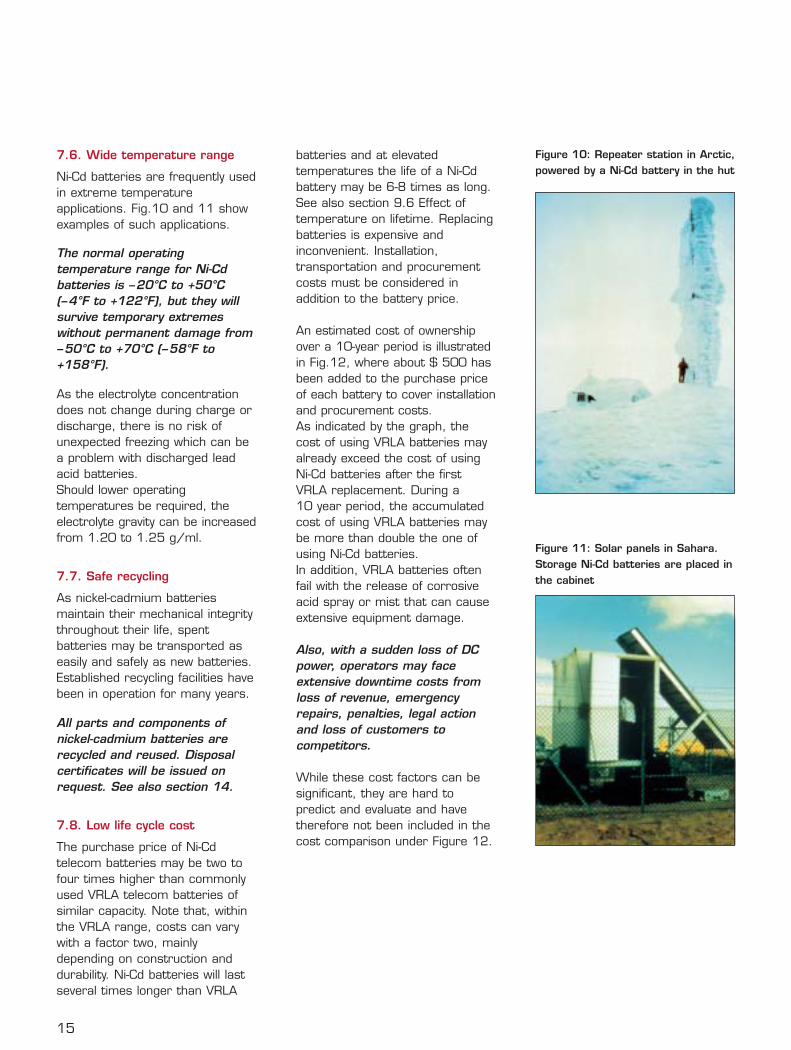
7.6. Wide temperature range
Ni-Cd batteries are frequently usedin extreme temperatureapplications. Fig.10 and 11 showexamples of such applications.
The normal operatingtemperature range for Ni-Cdbatteries is –20°C to +50°C(–4°F to +122°F), but they willsurvive temporary extremeswithout permanent damage from–50°C to +70°C (–58°F to+158°F).
As the electrolyte concentrationdoes not change during charge ordischarge, there is no risk ofunexpected freezing which can bea problem with discharged leadacid batteries.Should lower operatingtemperatures be required, theelectrolyte gravity can be increasedfrom 1.20 to 1.25 g/ml.
7.7. Safe recycling
As nickel-cadmium batteriesmaintain their mechanical integritythroughout their life, spentbatteries may be transported aseasily and safely as new batteries.Established recycling facilities havebeen in operation for many years.
All parts and components ofnickel-cadmium batteries arerecycled and reused. Disposalcertificates will be issued onrequest. See also section 14.
7.8. Low life cycle cost
The purchase price of Ni-Cdtelecom batteries may be two tofour times higher than commonlyused VRLA telecom batteries ofsimilar capacity. Note that, withinthe VRLA range, costs can varywith a factor two, mainlydepending on construction anddurability. Ni-Cd batteries will lastseveral times longer than VRLA
batteries and at elevatedtemperatures the life of a Ni-Cdbattery may be 6-8 times as long.See also section 9.6 Effect oftemperature on lifetime. Replacingbatteries is expensive andinconvenient. Installation,transportation and procurementcosts must be considered inaddition to the battery price.
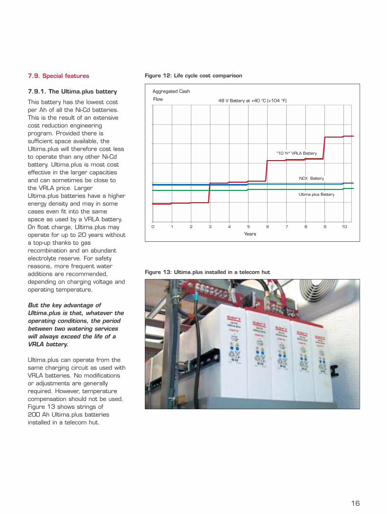
An estimated cost of ownershipover a 10-year period is illustratedin Fig.12, where about $ 500 hasbeen added to the purchase priceof each battery to cover installationand procurement costs.As indicated by the graph, thecost of using VRLA batteries mayalready exceed the cost of usingNi-Cd batteries after the firstVRLA replacement. During a10 year period, the accumulatedcost of using VRLA batteries maybe more than double the one ofusing Ni-Cd batteries.In addition, VRLA batteries oftenfail with the release of corrosiveacid spray or mist that can causeextensive equipment damage.
Also, with a sudden loss of DCpower, operators may faceextensive downtime costs fromloss of revenue, emergencyrepairs, penalties, legal actionand loss of customers tocompetitors.
While these cost factors can besignificant, they are hard topredict and evaluate and havetherefore not been included in thecost comparison under Figure 12.
15
Figure 10: Repeater station in Arctic,powered by a Ni-Cd battery in the hut
Figure 11: Solar panels in Sahara.Storage Ni-Cd batteries are placed inthe cabinet
16
7.9. Special features
7.9.1. The Ultima.plus battery
This battery has the lowest costper Ah of all the Ni-Cd batteries.This is the result of an extensivecost reduction engineeringprogram. Provided there issufficient space available, theUltima.plus will therefore cost lessto operate than any other Ni-Cdbattery. Ultima.plus is most costeffective in the larger capacitiesand can sometimes be close tothe VRLA price. LargerUltima.plus batteries have a higherenergy density and may in somecases even fit into the samespace as used by a VRLA battery.On float charge, Ultima.plus mayoperate for up to 20 years withouta top-up thanks to gasrecombination and an abundantelectrolyte reserve. For safetyreasons, more frequent wateradditions are recommended,depending on charging voltage andoperating temperature.
But the key advantage ofUltima.plus is that, whatever theoperating conditions, the periodbetween two watering serviceswill always exceed the life of aVRLA battery.
Ultima.plus can operate from thesame charging circuit as used withVRLA batteries. No modificationsor adjustments are generallyrequired. However, temperaturecompensation should not be used.Figure 13 shows strings of200 Ah Ultima.plus batteriesinstalled in a telecom hut.
Figure 13: Ultima.plus installed in a telecom hut
Figure 12: Life cycle cost comparison
48 V Battery at +40 °C (+104 °F)
0 1 2 3 4 5 6 7 8 9 10
Years
Aggregated Cash
Flow
Ultima.plus Battery
"10 Yr" VRLA Battery
NCX Battery
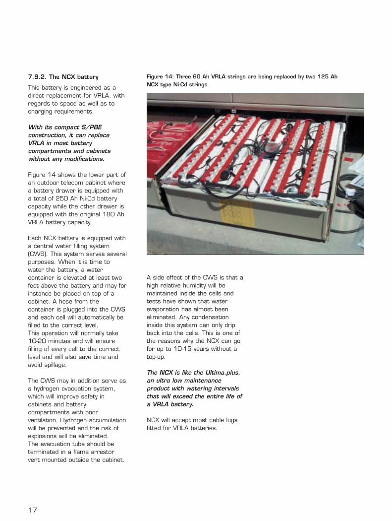
7.9.2. The NCX battery
This battery is engineered as adirect replacement for VRLA, withregards to space as well as tocharging requirements.
With its compact S/PBEconstruction, it can replaceVRLA in most batterycompartments and cabinetswithout any modifications.
Figure 14 shows the lower part ofan outdoor telecom cabinet wherea battery drawer is equipped witha total of 250 Ah Ni-Cd batterycapacity while the other drawer isequipped with the original 180 AhVRLA battery capacity.
Each NCX battery is equipped witha central water filling system(CWS). This system serves severalpurposes. When it is time towater the battery, a watercontainer is elevated at least twofeet above the battery and may forinstance be placed on top of acabinet. A hose from thecontainer is plugged into the CWSand each cell will automatically befilled to the correct level. This operation will normally take10-20 minutes and will ensurefilling of every cell to the correctlevel and will also save time andavoid spillage.
The CWS may in addition serve asa hydrogen evacuation system,which will improve safety incabinets and batterycompartments with poorventilation. Hydrogen accumulationwill be prevented and the risk ofexplosions will be eliminated. The evacuation tube should beterminated in a flame arrestorvent mounted outside the cabinet.
A side effect of the CWS is that ahigh relative humidity will bemaintained inside the cells andtests have shown that waterevaporation has almost beeneliminated. Any condensationinside this system can only dripback into the cells. This is one ofthe reasons why the NCX can gofor up to 10-15 years without atop-up.
The NCX is like the Ultima.plus,an ultra low maintenanceproduct with watering intervalsthat will exceed the entire life ofa VRLA battery.
NCX will accept most cable lugsfitted for VRLA batteries.
17
Figure 14: Three 60 Ah VRLA strings are being replaced by two 125 AhNCX type Ni-Cd strings
18
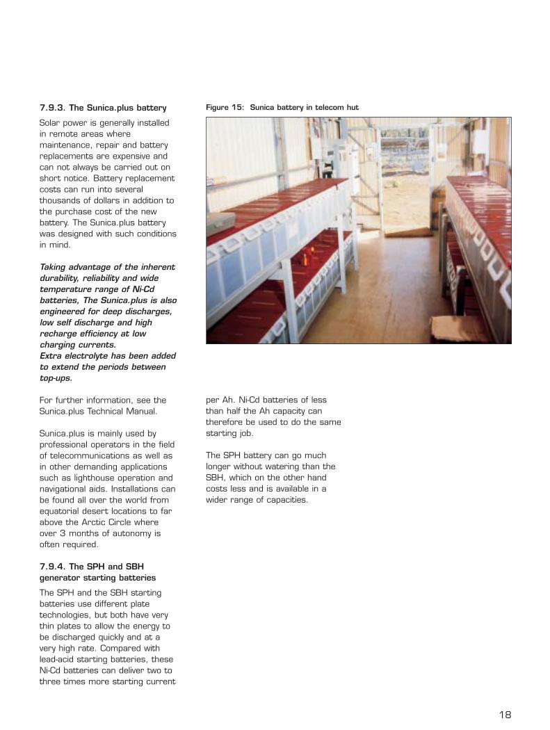
7.9.3. The Sunica.plus battery
Solar power is generally installedin remote areas wheremaintenance, repair and batteryreplacements are expensive andcan not always be carried out onshort notice. Battery replacementcosts can run into severalthousands of dollars in addition tothe purchase cost of the newbattery. The Sunica.plus batterywas designed with such conditionsin mind.
Taking advantage of the inherentdurability, reliability and widetemperature range of Ni-Cdbatteries, The Sunica.plus is alsoengineered for deep discharges,low self discharge and highrecharge efficiency at lowcharging currents. Extra electrolyte has been addedto extend the periods betweentop-ups.
For further information, see theSunica.plus Technical Manual.
Sunica.plus is mainly used byprofessional operators in the fieldof telecommunications as well asin other demanding applicationssuch as lighthouse operation andnavigational aids. Installations canbe found all over the world fromequatorial desert locations to farabove the Arctic Circle whereover 3 months of autonomy isoften required.
7.9.4. The SPH and SBHgenerator starting batteries
The SPH and the SBH startingbatteries use different platetechnologies, but both have verythin plates to allow the energy tobe discharged quickly and at avery high rate. Compared withlead-acid starting batteries, theseNi-Cd batteries can deliver two tothree times more starting current
per Ah. Ni-Cd batteries of lessthan half the Ah capacity cantherefore be used to do the samestarting job.
The SPH battery can go muchlonger without watering than theSBH, which on the other handcosts less and is available in awider range of capacities.
Figure 15: Sunica battery in telecom hut
Saft currently offers two ranges ofstandby batteries for regulartelecom applications, theUltima.plus and the NCX battery.In addition, Saft offers Sunica.plusbatteries for PV (photovoltaic)applications and the SPH andSBH series of batteries forgenerator starting.
Various numbers of cells areconnected in series, depending ofthe voltage of the telecom system:
• The voltage window may varyaccording to national standards.In the US, Telcordia hasrecommended that 38 Ni-Cdcells should be used in a 48 Vstring, but other markets maysee 36-40 cells depending onspecified voltage levels.
• Similarly, 24 V systemscommonly used in cellular andmicrowave systems may consistof 18 to 20 cells.
• For starting applications,10 cells are normally used for12 V systems and 20 cells for24 V systems
• In PV applications, eight to tencells may be used, depending onthe specified voltage window andoperating conditions
• Cable TV networks generally usea 36 V battery that feeds thecable amplifiers through an on-line inverter.
The following is a brief discussionof various applications where Safttelecom batteries may offersubstantial benefits over thetraditional VRLA battery.
8.1. Remote cabinets in accessnetworks
The use of outdoor cabinets in theaccess network started in the USAin the 70’s. The early cabinetstypically contained a few localsubscriber circuits and a systemthat connected the subscribers to
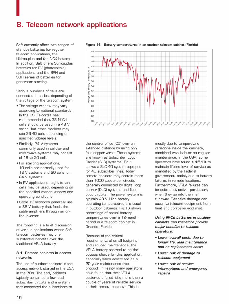
the central office (CO) over anextended distance by using onlyfour copper wires. These systemsare known as Subscriber LoopCarrier (SLC) systems. Fig.1shows a SLC 40 system equippedfor 40 subscriber lines. Todayremote cabinets may contain morethan 1000 subscriber circuitsgenerally connected by digital loopcarrier (DLC) systems and fiberoptic circuits. The power system istypically 48 V. High batteryoperating temperatures are usualin outdoor cabinets. Fig.16 showsrecordings of actual batterytemperatures over a 12-monthperiod in a telecom cabinet inOrlando, Florida.
Because of the criticalrequirements of small footprintand reduced maintenance, theVRLA battery seemed to be theobvious choice for this application,especially when advertised as a20 year maintenance freeproduct. In reality many operatorshave found that their VRLAbatteries offered little more than acouple of years of reliable servicein their remote cabinets. This is
mostly due to temperaturevariations inside the cabinets,combined with little or no regularmaintenance. In the USA, someoperators have found it difficult tomaintain lifeline level of service asmandated by the Federalgovernment, mainly due to batteryfailures in remote locations.Furthermore, VRLA failures canbe quite destructive, particularlywhen they go into thermalrunaway. Extensive damage canoccur to telecom equipment fromheat and corrosive acid mist.
Using Ni-Cd batteries in outdoorcabinets can therefore providemajor benefits to telecomoperators:
• Lower overall costs due tolonger life, less maintenanceand no replacement costs
• Lower risk of damage totelecom equipment
• Lower risk of serviceinterruptions and emergencyrepairs
19
8. Telecom network applications
20
22
24
26
28
30
32
34
36
38
40
42
44
46
48
Ave
rage
dai
ly B
atte
ry T
empe
ratu
re (°C
)
mai-
97
juin-9
7
juin-9
7
juil-9
7
juil-9
7
aoû-9
7
aoû-9
7
sep-9
7
sep-9
7
oct-9
7
oct-9
7
nov-9
7
nov-9
7
déc-9
7
déc-9
7
jan-98
jan-98
fév-9
8
fév-9
8
mar
-98
mar
-98
avr-9
8
avr-9
8
mai-
98
mai-
98
juin-9
8
juin-9
8
juil-9
8
Figure 16: Battery temperatures in an outdoor telecom cabinet (Florida)
20
Most power systems in outdoorcabinets are of the “bulk power”type, while some of the earlierSLC systems such as SLC96,used “distributed power”.
Bulk power is simply a systemwhere several rectifiers connectedin parallel feed the load circuitsand at the same time float chargeone or several parallel strings ofbatteries. Typically, several parallelstrings of 60 to 160 Ah batteriesare utilized for bulk powerinstallations in outdoor cabinets.
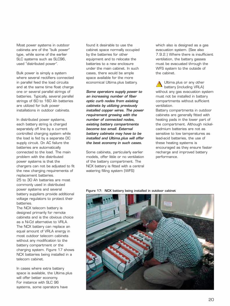
In distributed power systems,each battery string is chargedseparately off line by a currentcontrolled charging system whilethe load is fed by a separate DCsupply circuit. On AC failure thebatteries are automaticallyconnected to the load. The mainproblem with the distributedpower systems is that thechargers can not be adjusted to fitthe new charging requirements ofreplacement batteries. 25 to 30 Ah batteries are mostcommonly used in distributedpower systems and severalbattery suppliers provide additionalvoltage regulators to protect theirbatteries.The NCX telecom battery isdesigned primarily for remotecabinets and is the obvious choiceas a Ni-Cd alternative to VRLA.The NCX battery can replace anequal amount of VRLA energy inmost outdoor telecom cabinetswithout any modification to thebattery compartment or thecharging system. Figure 17 showsNCX batteries being installed in atelecom cabinet.
In cases where extra batteryspace is available, the Ultima.pluswill offer better economy. For instance with SLC 96systems, some operators have
found it desirable to use thecabinet space normally occupiedby the batteries for otherequipment and to relocate thebatteries to a new enclosureunder the main cabinet. In suchcases, there would be amplespace available for the moreeconomical Ultima.plus battery.
Some operators supply power toan increasing number of fiberoptic curb nodes from existingcabinets by utilizing previouslyinstalled copper wires. The powerrequirement growing with thenumber of connected nodes,existing battery compartmentsbecome too small. Externalbattery cabinets may have to beinstalled and Ultima.plus will offerthe best economy in such cases.
Some cabinets, particularly earliermodels, offer little or no ventilationof the battery compartment. TheNCX battery is fitted with a centralwatering filling system (WFS)
which also is designed as a gasevacuation system. (See also7.9.2.) Where there is insufficientventilation, the battery gassesmust be evacuated through theWFS system to the outside of the cabinet.
Ultima.plus or any otherbattery (including VRLA)
without any gas evacuation systemmust not be installed in batterycompartments without sufficientventilation. Battery compartments in outdoorcabinets are generally fitted withheating pads in the lower part ofthe compartment. Although nickel-cadmium batteries are not assensitive to low temperatures aslead-acid batteries, the use ofthese heating systems isencouraged as they ensure fasterrecharge and improved batteryperformance.
Figure 17: NCX battery being installed in outdoor cabinet
8.2. CEVs, huts and shelters
CEVs (Controlled EnvironmentalVaults), huts and shelters used inthe local area network generallyaccommodate larger remoteinstallations than those housed incabinets. A typical hut isillustrated in Fig.7. The equipmentis mounted in open telecom racksas used in CO (Central Office)installations and may consist ofswitching systems, DLC,multiplexers, fiber optics, etc…
The batteries have traditionallybeen of the VRLA type and havebeen installed in battery racks oron trays mounted on telecomracks, adjacent to other telecomequipment. Any venting of VRLAbattery gasses or any destructivefailures could therefore damagethe electronic equipment close by.Venting of Ni-Cd batteries does notcarry any destructive amounts ofcorrosive fumes, and flooded Ni-Cdbatteries can therefore be safelymounted next to electronicequipment.
Generally, it is 48 V bulk powersystems that are installed in CEVsand huts, but some of the olderinstallations may contain SLCsystems with distributed power.The bulk power batteries generallyconsist of parallel strings, mostlyof 100 Ah batteries butsometimes even a single string ofa much larger capacity may beinstalled. Total installed batterycapacity may vary from 400 toabout 1600 Ah.
CEVs and huts are equipped withheating and cooling. Temperaturesare not as tightly controlled as inCO locations, but the batteries willnot face the very hightemperatures they are exposed toin outdoor cabinets. Even so,many operators complain aboutshort battery life and destructive
failures of VRLA batteries andsome have started to install Ni-Cdbatteries to avoid such problems.Large capacity Ultima.plus is veryprice competitive in thisapplication and sufficient space isoften available.
Many CEVs and huts have limitedventilation to the outside in spiteof the fact that industry safetystandards and regulations clearlyrequire a substantial rate of airchange. Continuous ventilation is arequirement for all rooms andenclosures where batteries arebeing charged. This also applies toVRLA batteries.
8.3. Customer premises
Several types of equipment may beinstalled at the end-user,depending on the requirement.Smaller installations may fit in asingle indoor cabinet, with a30 Ah battery installed on thebottom shelf. Larger installationsmay require open telecom racks ina dedicated equipment room.Most of the operators offerstandard equipment solutions. The battery requirements will varyaccordingly and generally bulkpower systems are used.
In cabinets with restricted batteryspace, the NCX is the only batterythat will fit. For open rackinstallations, the Ultima.plus canoften be accommodated.
8.4. Central offices (CO)
Traditionally, central officeequipment is supported by parallelstrings of flooded lead-acidbatteries of the best industrialquality in capacities up to severalthousands Ah. These batteries areinstalled in separate battery roomsto avoid equipment damage fromcorrosive acid fumes. Batteries inCOs are generally well maintained
21
22
and operated under idealconditions and will thereforeprovide many years of reliable andeconomical service. There arerelatively few complaints aboutthese types of battery installation.
Many operators have equippedsmall, unmanned COs with VRLAbatteries.They are often lesssatisfied with these batteries due toshorter life and higher operatingcosts than anticipated. Someoperators have therefore installedNi-Cd batteries to avoid problemsand to reduce operating costs.Most CO locations are equippedwith diesel generators as protectionagainst long utility power outages.These generators are of little use ifthey do not start when they areneeded. Therefore, the startingbattery is a critical component thatmust absolutely work.
The cost of the battery isrelatively minor compared to thetotal cost of the diesel generatorand its associated equipment,and many operators have learntthat trying to save money bybuying a cheap starting batteryis false economy.
Starting problems, frequentbattery replacements and highmaintenance costs will quicklybridge the difference in batteryprice between a lead acid and aproperly selected Ni-Cd battery.Saft’s SPH and SBH range ofbatteries are designed forstationary diesel startingapplications. Some of the majortelecom operators havestandardized on such batteries forall diesel starting applications.
8.5. Cellular systems
Modern cellular networks are verydiverse and complex. Their powerbackup needs range from remote,
low powered base stations toswitching centers requiring largebanks of batteries of severalthousands of Ah. Batterymaintenance is always a problemin a geographically dispersedsystem and the cost of frequentbattery replacements and poorreliability is a serious problem formany operators.
Installations that are the bestcandidates for Ni-Cd batteriesare in remote locations and incritical parts of cellularnetworks, such as switchingcenters and other locations thatchannel multiple circuits.
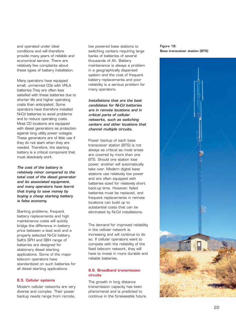
Power backup of each basetransceiver station (BTS) is notalways as critical as most areasare covered by more than oneBTS. Should one station losepower, another will automaticallytake over. Modern digital basestations use relatively low powerand are often equipped withbatteries sized for relatively shortback-up time. However, failedbatteries must be replaced, andfrequent replacements in remotelocations can build up tosubstantial costs that can beeliminated by Ni-Cd installations.
The demand for improved reliabilityin the cellular network isincreasing and will continue to doso. If cellular operators want tocompete with the reliability of thefixed telecom network, they willhave to invest in more durable andreliable batteries.
8.6. Broadband transmissioncircuits
The growth in long distancetransmission capacity has beenphenomenal and is predicted tocontinue in the foreseeable future.
Figure 18: Base transceiver station (BTS)
23
This is mainly due to increasedInternet and data transmissiontraffic. There are severaltechnologies involved in thisgrowth, such as fiber optics inboth land-based cables as well asin submarine cables, microwavesystems and satellite links. Allthese technologies require reliablepower, at their terminals and inamplifier and repeater stations. To a large extent, terminals arelocated in CO environments withlarge battery installations asdescribed above.
However, many of the amplifierand repeater stations arelocated in remote areas whereservice visits are expensive. Asthese circuits carry largevolumes of traffic, reliability is ofoutmost importance and powerfailures cannot be tolerated.Such remote locations couldbenefit from the reliability andthe durability of Ni-Cd batteries.
Other utility companies such asrailroads, electric utilities andpipeline companies have enteredthe telecom industry. They areusing their right-of-way where theyinstall telecom transmission lines,mainly fiber optic cables. Theirtransmission capacity is frequentlysold to telecom service providers,with guaranteed quality of service.Reliable power is therefore animportant requirement and asmany of these installations are inremote areas, Ni-Cd batteriesoffer many advantages.Furthermore, as many utilitycompanies have already utilized Ni-Cd batteries in non-telecomapplications for several decades,they are often familiar with theadvantages and appreciate theircost saving features.Both NCX and Ultima.plus arebeing used by utilities for theprotection of their telecom
diversifications. Batteries aregenerally installed in remote hutsin a bulk power configuration.
8.7. Cable TV
Most of us that live in rural orsuburban areas and enjoy cabletelevision, have experienced that insevere weather it is notuncommon to lose service. For those who are familiar withthe distribution of cable serviceand the power backup system,this is not a surprise. With severalamplifier stations along the cableroute and with each stationreceiving power through aninverter backed up by a low costVRLA battery, it is obvious thatthere are many weak links thatcan fail. And it will only take onefailure to eliminate service to allthose that are connected furtherdown the line.
As cable companies areimplementing telephone and datacommunications services incompetition with the telephonecompanies, they have found itnecessary to improve their powerbackup system significantly. Ni-Cd batteries offer outstandingbenefits to operators in thisenvironment, particularly in termsof reliability and durability as wellas lower operating costs.
24
9. Operating features
9.1. Capacity
The Ni-Cd battery is rated inampere-hours (Ah) whichcorresponds to the quantity ofelectricity that can be suppliedunder specified conditions.According to standards(International ElectrotechnicalCommission, IEC), Ni-Cd batteriesare rated at room temperature ata 5 hour discharge rate to an endvoltage of 1.0 V per cell and afterconstant current charging.
This also applies to Saft’s batteriesexcept the NCX and theUltima.plus, which primarily aredesigned for telecom floatcharging conditions, and optimizedfor 8 hours standby. The ratedcapacity of NCX and Ultima.plus istherefore based on an 8 hourdischarge at +25°C (+77°F) to anend voltage of 1.1 V per cell andafter 24 hours on float charge.The actual available capacity orperformance during operation will,for all batteries, vary with rate ofdischarge, temperature, charginghistory and end voltage.
9.2. Current rates
Charging and discharging maytake place at different rates ofcurrent relative to the battery’srated capacity. It is common inbattery literature that the batterycurrent is expressed as a fractionof the nominal battery capacity“C”. For instance, a current rateof 0.2 C means that the currentis 0.2 or 20% of the batterycapacity (expressed in Ampere).For a 100 Ah battery the 0.2 Crate is 20 A and the 0.1 C rate is10 A. The 0.2 C rate may also bewritten as C/5. As this is close tothe 5 hour rate of a battery, it issometimes considered the same.
For most batteries the C/2 (or 0.5 C) current is considerablyhigher than a sustainable 2 hourcurrent. Therefore, do not expectthe C/2 rate to last for two hoursor the C rate to last for one hour.
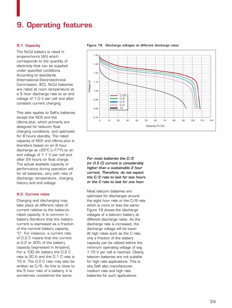
Most telecom batteries areoptimized for discharges aroundthe eight hour rate or the C/8 ratewhich is more or less the same.Figure 19 shows the dischargevoltages of a telecom battery atdifferent discharge rates. As thedischarge rate is increased, thedischarge voltage will be lower. At high rates such as the C rate,only a fraction of the batterycapacity can be utilized before theminimum operating voltage of say,1.10 V per cell is reached. Clearly,telecom batteries are not suitablefor high rate applications. This iswhy Saft also manufacturesmedium rate and high ratebatteries for such applications.
0.70
0.80
0.90
1.00
1.10
1.20
1.30
1.40
0 10 20 30 40 50 60 70 80 90 100 110 120
Capacity (% Cn)
Volta
ge (v)
1CC/3C/5C/8C/24
Figure 19: Discharge voltages at different discharge rates
25
9.3. Cell voltage
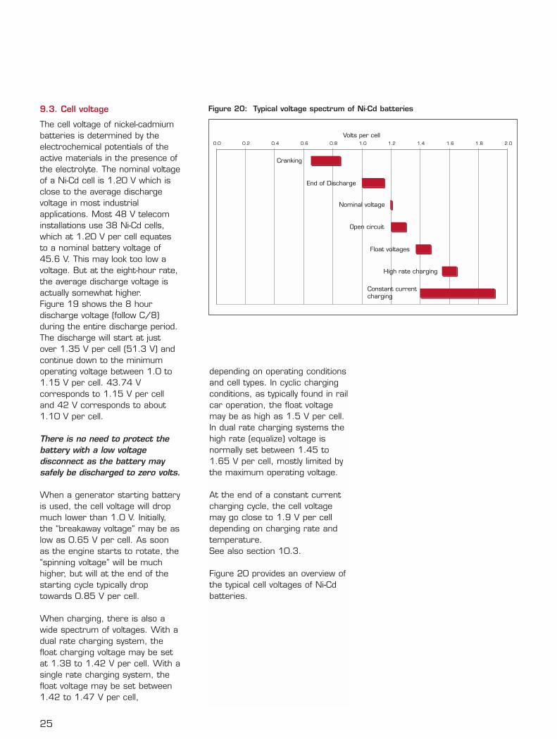
The cell voltage of nickel-cadmiumbatteries is determined by theelectrochemical potentials of theactive materials in the presence ofthe electrolyte. The nominal voltageof a Ni-Cd cell is 1.20 V which isclose to the average dischargevoltage in most industrialapplications. Most 48 V telecominstallations use 38 Ni-Cd cells,which at 1.20 V per cell equatesto a nominal battery voltage of45.6 V. This may look too low avoltage. But at the eight-hour rate,the average discharge voltage isactually somewhat higher.Figure 19 shows the 8 hourdischarge voltage (follow C/8)during the entire discharge period.The discharge will start at justover 1.35 V per cell (51.3 V) andcontinue down to the minimumoperating voltage between 1.0 to1.15 V per cell. 43.74 Vcorresponds to 1.15 V per celland 42 V corresponds to about1.10 V per cell.
There is no need to protect thebattery with a low voltagedisconnect as the battery maysafely be discharged to zero volts.
When a generator starting batteryis used, the cell voltage will dropmuch lower than 1.0 V. Initially,the “breakaway voltage” may be aslow as 0.65 V per cell. As soonas the engine starts to rotate, the“spinning voltage” will be muchhigher, but will at the end of thestarting cycle typically droptowards 0.85 V per cell.
When charging, there is also awide spectrum of voltages. With adual rate charging system, thefloat charging voltage may be setat 1.38 to 1.42 V per cell. With asingle rate charging system, thefloat voltage may be set between1.42 to 1.47 V per cell,
Constant currentcharging
High rate charging
Float voltages
Open circuit
Nominal voltage
End of Discharge
Cranking
0.0 0.2 0.4 0.6 0.8 1.0 1.2 1.4 1.6 1.8 2.0
Volts per cell
Figure 20: Typical voltage spectrum of Ni-Cd batteries
depending on operating conditionsand cell types. In cyclic chargingconditions, as typically found in railcar operation, the float voltagemay be as high as 1.5 V per cell.In dual rate charging systems thehigh rate (equalize) voltage isnormally set between 1.45 to1.65 V per cell, mostly limited bythe maximum operating voltage.
At the end of a constant currentcharging cycle, the cell voltagemay go close to 1.9 V per celldepending on charging rate andtemperature. See also section 10.3.
Figure 20 provides an overview ofthe typical cell voltages of Ni-Cdbatteries.
26
9.4. Internal resistance
The internal resistance orimpedance of a Ni-Cd cell willchange only slightly with state ofcharge or battery age, thanks tothe permanent concentration ofthe electrolyte. Therefore,repeated impedance testing doesnot provide a good indication ofthe condition of a cell or battery.
Thanks to the relatively limitedvariation of cell impedance withstate of charge, a 50% chargedstarting battery will, for instance,deliver more than 80% of its fullycharged starting current.
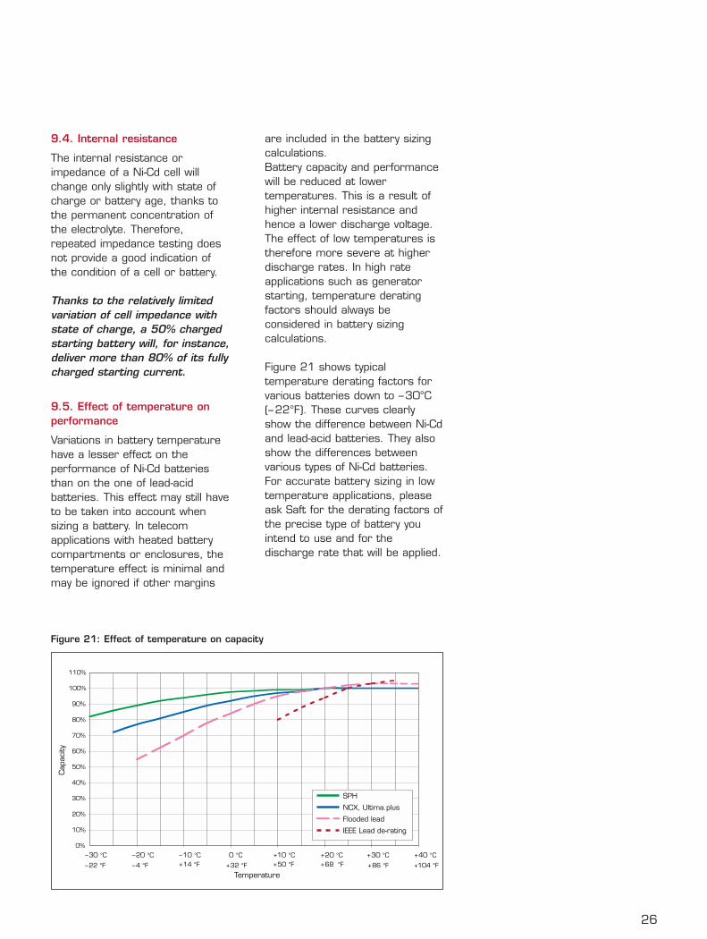
9.5. Effect of temperature onperformance
Variations in battery temperaturehave a lesser effect on theperformance of Ni-Cd batteriesthan on the one of lead-acidbatteries. This effect may still haveto be taken into account whensizing a battery. In telecomapplications with heated batterycompartments or enclosures, thetemperature effect is minimal andmay be ignored if other margins
are included in the battery sizingcalculations.Battery capacity and performancewill be reduced at lowertemperatures. This is a result ofhigher internal resistance andhence a lower discharge voltage.The effect of low temperatures istherefore more severe at higherdischarge rates. In high rateapplications such as generatorstarting, temperature deratingfactors should always beconsidered in battery sizingcalculations.
Figure 21 shows typicaltemperature derating factors forvarious batteries down to –30°C(–22°F). These curves clearlyshow the difference between Ni-Cdand lead-acid batteries. They alsoshow the differences betweenvarious types of Ni-Cd batteries.For accurate battery sizing in lowtemperature applications, pleaseask Saft for the derating factors ofthe precise type of battery youintend to use and for thedischarge rate that will be applied.
0%
10%
20%
30%
40%
50%
60%
70%
80%
90%
100%
110%
– 30 °C – 20 °C – 10 °C 0 °C +10 °C + 20 °C + 30 °C + 40 °C
Temperature
Cap
acity
– 22 °F – 4 °F + 14 °F + 32 °F + 50 °F + 68 °F + 86 °F +104 °F
SPH
NCX, Ultima.plus
Flooded lead
IEEE Lead de-rating
Figure 21: Effect of temperature on capacity
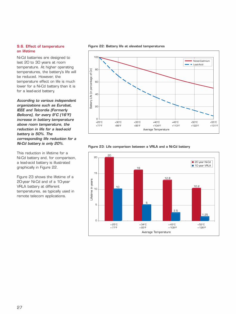
9.6. Effect of temperature on lifetime
Ni-Cd batteries are designed tolast 20 to 30 years at roomtemperature. At higher operatingtemperatures, the battery’s life willbe reduced. However, thetemperature effect on life is muchlower for a Ni-Cd battery than it isfor a lead-acid battery.
According to various independentorganizations such as Eurobat,IEEE and Telcordia (FormerlyBellcore), for every 9°C (16°F)increase in battery temperatureabove room temperature, thereduction in life for a lead-acidbattery is 50%. Thecorresponding life reduction for aNi-Cd battery is only 20%.
This reduction in lifetime for a Ni-Cd battery and, for comparison,a lead-acid battery is illustratedgraphically in Figure 22.
Figure 23 shows the lifetime of a20-year Ni-Cd and of a 10-yearVRLA battery at differenttemperatures, as typically used inremote telecom applications.
27
0
20
40
60
80
100
+25°C +30°C +35°C +40°C +45°C +50°C +55°C
+77°F +86°F +95°F +104°F +113°F +122°F +131°F
Average Temperature
Bat
tery
Life
(in
per
cent
age
of C
n)
Nickel-Cadmium
Lead-Acid
Figure 22: Battery life at elevated temperatures
20
16
12.8
10.210
5
2.5
1.25
0
5
10
15
20
+ 25°C+ 77°F
+ 34°C+ 93°F
+ 43°C+ 109°F
+ 52°C+ 126°F
Average Temperature
Life
time
in y
ears
20 year Ni-Cd10 year VRLA
Figure 23: Life comparison between a VRLA and a Ni-Cd battery
28
9.7. Short circuit values
The short circuit current dependson several factors such as batterycapacity, state of charge,temperature and the internalimpedance of the battery. A fullycharged NCX or Ultima.plusbattery can deliver a peak currentof about 10 C (Ten times the Ahrating expressed in amperes), andan SPH or SBH cell can deliveraround 30 C. This means that a100 Ah string of Ultima.plus orNCX telecom battery can deliverup to 1000 A in a short circuitsituation.
This is more than enough tomelt any metallic watchstraps
or jewelry, and such objects musttherefore be removed beforehandling batteries to avoid seriousburns. All charged batteries mustbe handled with respect and care.Even a half-charged battery candeliver more than 80% of its fullycharged short circuit current. At –20°C (+4°F) the short circuitcurrent may be reduced to abouthalf the room temperature current.
9.8. Self discharge
The state of charge of Ni-Cdbatteries on open circuit will slowlydecrease with time due to self-discharge. In practice, thisdecrease is relatively rapid duringthe first few days, but will laterstabilize at about 2% per month at+25°C (+77°F) depending on thetype of battery. Batterytemperature affects the rate ofself-discharge significantly. At lowtemperatures, the chargeretention is much better than atroom temperature and at highertemperatures the rate of selfdischarge will increase rapidly.
However, the effect of selfdischarge is much less significantfor a Ni-Cd battery than it is for a
lead-acid battery. At a reducedstate of charge, lead acidbatteries will soon begin to sufferfrom irreversible sulfating of theactive material that will result in apermanent loss of capacity. Ni-Cd batteries do not suffer fromany similar effects.
S/PBE batteries can be storedcompletely discharged for yearswithout any signs of damage.
A Ni-Cd battery that has beenallowed to self discharge for morethan 6 months may need areconditioning charge to recoverfull capacity.
Before storing Ni-Cd batteries fora longer period than 6 months,please follow the recommendedoperating procedures.
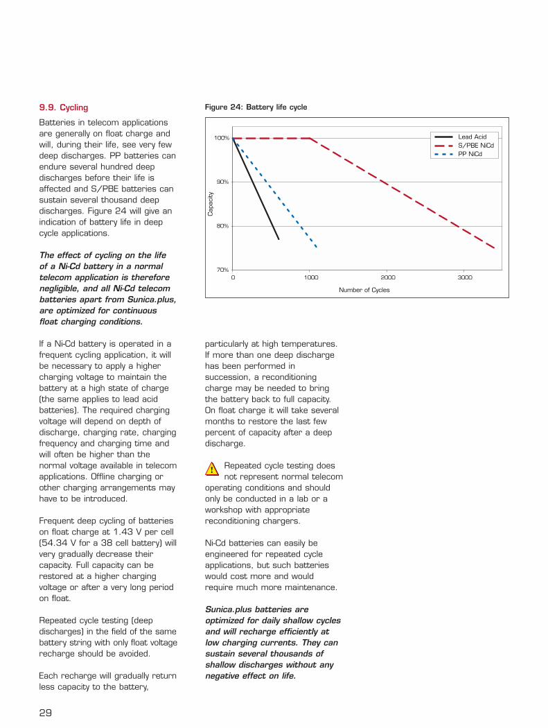
9.9. Cycling
Batteries in telecom applicationsare generally on float charge andwill, during their life, see very fewdeep discharges. PP batteries canendure several hundred deepdischarges before their life isaffected and S/PBE batteries cansustain several thousand deepdischarges. Figure 24 will give anindication of battery life in deepcycle applications.
The effect of cycling on the lifeof a Ni-Cd battery in a normaltelecom application is thereforenegligible, and all Ni-Cd telecombatteries apart from Sunica.plus,are optimized for continuousfloat charging conditions.
If a Ni-Cd battery is operated in afrequent cycling application, it willbe necessary to apply a highercharging voltage to maintain thebattery at a high state of charge(the same applies to lead acidbatteries). The required chargingvoltage will depend on depth ofdischarge, charging rate, chargingfrequency and charging time andwill often be higher than thenormal voltage available in telecomapplications. Offline charging orother charging arrangements mayhave to be introduced.
Frequent deep cycling of batterieson float charge at 1.43 V per cell(54.34 V for a 38 cell battery) willvery gradually decrease theircapacity. Full capacity can berestored at a higher chargingvoltage or after a very long periodon float.
Repeated cycle testing (deepdischarges) in the field of the samebattery string with only float voltagerecharge should be avoided.
Each recharge will gradually returnless capacity to the battery,
particularly at high temperatures.If more than one deep dischargehas been performed insuccession, a reconditioningcharge may be needed to bringthe battery back to full capacity.On float charge it will take severalmonths to restore the last fewpercent of capacity after a deepdischarge.
Repeated cycle testing doesnot represent normal telecom
operating conditions and shouldonly be conducted in a lab or aworkshop with appropriatereconditioning chargers.
Ni-Cd batteries can easily beengineered for repeated cycleapplications, but such batterieswould cost more and wouldrequire much more maintenance.
Sunica.plus batteries areoptimized for daily shallow cyclesand will recharge efficiently atlow charging currents. They cansustain several thousands ofshallow discharges without anynegative effect on life.
29
70%
80%
90%
100%
0 1000 2000 3000
Number of Cycles
Cap
acity
Lead AcidS/PBE NiCdPP NiCd
Figure 24: Battery life cycle
30
9.10. Water consumption
Battery water consumption isbasically a result of overcharging(water electrolysis) andevaporation. Theoretically, after abattery is fully charged, it will useup to 1/3 ml of water per cell,per A and per hour. In addition,water losses from evaporation canbe considerable and may in manysituations exceed water lossesfrom electrolysis. Waterconsumption will increase rapidlywith the temperature, due tohigher evaporation as well as tothe effect of higher float currents.
Water replenishment has alwaysbeen part of battery life. But withthe increase of maintenance costs,efforts have been made to reducethe battery water consumption.Some battery systems, such asthe VRLA batteries, areengineered to allow maximum gasrecombination to reduce oreliminate water losses. To ensureproper battery operation andreduction of water evaporation, theVRLA cells are sealed from theatmosphere by a pressure releasevalve. A drawback is that the VRLAbatteries will generate a certainamount of heat on chargedepending on how much gas theyhave to recombine.
Different types of Ni-Cd batteriesemploy different techniques toreduce their water consumptionand to increase time betweentop-ups.
The Ultima.plus battery has agenerous electrolyte reservecombined with a 85-95% efficientgas recombination system whichwill allow the battery to stay onfloat charge for up to 20 yearswithout water replenishment.
With its S/PBE plateconstruction, the NCX battery has
a very low float current, about0.4 mA per Ah. Furthermore, theNCX water filling system (WFS)more or less eliminates theproblem of evaporation. Testshave confirmed that this batterycan operate for well over 10 yearswithout a top-up.
The SPH battery does not haveany WFS, but a combination ofvery low float currents and alarger electrolyte reserve makes itpossible to operate well over10 years without watering.
Sunica.plus and the SBH batterieshave large electrolyte reservesand can operate up to 3 yearswithout maintenance.
9.11. Gas evolution
All Ni-Cd as well as lead acidbatteries produce hydrogen andoxygen gas on charge. Duringcontinued floating of a fully chargedcell, each Ah of overcharge willproduces 0.23 liters (0.008 cubicfeet) of oxygen and 0.46 liters(0.016 cubic feet) of hydrogen.
As mentioned above, somebatteries employ recombinationtechniques to recombinehydrogen and oxygen to water,and as long as the recombinationsystem works efficiently, theamount of gasses escaping fromthe batteries will be minimal.
However, recombination systemscan only handle a limited amountof charging current and may fail tooperate properly for variousreasons.
Be aware that national safetyregulations and standards do notonly consider hydrogen evolutionunder normal operatingconditions, but will requirecalculations for worst case andabnormal conditions such as loss
of voltage control and full chargingcurrent being applied to thebattery. Ventilation requirementsdepend therefore more on ratedcharger output than rated batterycapacity. Most safety standardsrequire the same ventilation forVRLA as for flooded batteries.
Do not presume that anybattery is sealed and never
install batteries in a sealedenclosure. All batteries on chargerequire generous and continuousventilation.
Contrary to open lead-acidbatteries, Ni-Cd batteries do notemit any destructive amounts ofcorrosive fumes.

Ni-Cd batteries can be chargedby any of the common chargingmethods such as constantvoltage or constant current.
In telecom applications, constantvoltage is most common andseveral strings of batteries may becharged in parallel, whileconnected to the load.
Constant current is not commonlyused with standby systems, as itwill lead to elevated voltages andoff-line charging may be required.
Ni-Cd batteries may beoptimized for different
charging conditions. For optimumperformance, operatinginstructions should be strictlyfollowed. Remember that they arespecific to each Ni-Cd battery type.
10.1. Constant voltage charging
Most telecom installations employa single rate, constant voltagecharging system. Several rectifiersconnected in parallel may be wiredor plugged in to the main DC bus.Similarly, several battery stringsmay be connected to the same DCbus. In some cases a breaker isinstalled for each battery string. In the USA, this system of parallelrectifiers and batteries is referredas to a “Bulk Power System”.
Single rate constant voltagecharging of Ni-Cd batteries alwaysrepresents a compromise: bymaintaining the voltage as low aspossible, minimum overcharge andminimum water consumption willoccur. But after a discharge it willtake longer to bring the batteriesback to full capacity and thebatteries may, for some period,operate below 100% state ofcharge. This will not reducebattery life, but full battery capacitymay not always be available.
In other words, the lowestpossible charging voltage isdesirable from a maintenancepoint of view while a highercharging voltage is needed forfaster recharge.The charging voltage shouldtherefore be chosen carefully toobtain an acceptable level ofrecharge without increasedmaintenance costs.
Ni-Cd batteries may be chargedcontinuously from 1.42 to1.47 V per cell, and most Ni-Cdbatteries will recharge to a highstate of charge within 24 hoursat those levels. Most 48 Vtelecom installations will chargeat around 1.43 V per cell, whichcorrespond to 54.35 V for38 cells.
Temperature compensation isnot recommended.
Charging at a higher voltage levelwill not be detrimental to thebattery, but will cause increasedmaintenance as the batteries willuse more water. Figure 25 showsvoltage and current for an 48V
NCX battery being recharged at amaximum current of 0.1 C and1.43 V per cell.
A dual level constant voltagecharging system is generally usedfor charging of generator startingbatteries. This has certainadvantages, as it will allow thebatteries to be fully charged muchfaster at the “high rate” charginglevel, normally set at 1.45 to1.65 V per cell. The float charginglevel can be set as low as 1.38 Vper cell because the batteries arefully charged when they areswitched to float. At 1.38 V percell, the water consumption is verylow and maintenance costs can bereduced. When dual levelchargers are used, an automaticdevice can be utilized to switchbetween the charging levels.
It is particularly important that atimer or some kind of automaticdevice is employed to switch tofloat charge after dual levelrecharge because continuous highrate charging could deplete thebattery of water within a few days.
31
10. Battery charging
Typical Recharge Characteristics of NCX batteryConstant voltage charging at 54.35 V and 0.1 C current limit at +25°C (+77°F)
45
46
47
48
49
50
51
52
53
54
55
0 2 4 6 8 10 12 14 16 18 20 22 24
Charge Time (hrs)
Str
ing
Volta
ge
0.000
0.025
0.050
0.075
0.100
0.125
0.150
0.175
0.200
0.225
0.250
C-R
ate
Rate factorAmps=(C-Rate)*(Rated Capacity)
String Voltage
Figure 25: Recharging at constant voltage
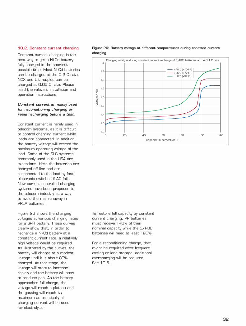
Charging volatges during constant current recharge of S/PBE batteries at the 0.1 C rate
1.2
1.3
1.4
1.5
1.6
1.7
1.8
1.9
2
0 20 40 60 80 100 120
Capacity (in percent of C°)
Volts
per
cel
l
+ 40°C (+ 104°F)+ 25°C (+ 77°F)
0°C (+ 32°F)
Figure 26: Battery voltage at different temperatures during constant currentcharging
32
10.2. Constant current charging
Constant current charging is thebest way to get a Ni-Cd batteryfully charged in the shortestpossible time. Most Ni-Cd batteriescan be charged at the 0.2 C rate.NCX and Ultima.plus can becharged at 0.05 C rate. Pleaseread the relevant installation andoperation instructions.
Constant current is mainly usedfor reconditioning charging orrapid recharging before a test.
Constant current is rarely used intelecom systems, as it is difficultto control charging current whileloads are connected. In addition,the battery voltage will exceed themaximum operating voltage of theload. Some of the SLC systemscommonly used in the USA areexceptions. Here the batteries arecharged off line and arereconnected to the load by fastelectronic switches if AC fails.New current controlled chargingsystems have been proposed tothe telecom industry as a way to avoid thermal runaway in VRLA batteries.
Figure 26 shows the chargingvoltages at various charging ratesfor a SPH battery. These curvesclearly show that, in order torecharge a Ni-Cd battery at aconstant current rate, a relativelyhigh voltage would be required. As illustrated by the curves, thebattery will charge at a modestvoltage until it is about 80%charged. At that stage, thevoltage will start to increaserapidly and the battery will start to produce gas. As the batteryapproaches full charge, thevoltage will reach a plateau andthe gassing will reach itsmaximum as practically allcharging current will be used for electrolysis.
To restore full capacity by constantcurrent charging, PP batteriesmust receive 140% of theirnominal capacity while the S/PBEbatteries will need at least 120%.
For a reconditioning charge, thatmight be required after frequentcycling or long storage, additionalovercharging will be required. See 10.6.
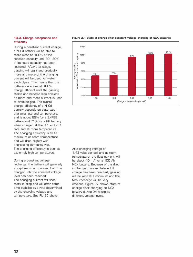
33
10.3. Charge acceptance andefficiency
During a constant current charge,a Ni-Cd battery will be able tostore close to 100% of thereceived capacity until 70 - 80%of its rated capacity has beenrestored. After that stage,gassing will start and graduallymore and more of the chargingcurrent will be used for waterelectrolysis. This means that thebatteries are almost 100%charge efficient until the gassingstarts and become less efficientas more and more current is usedto produce gas. The overallcharge efficiency of a Ni-Cdbattery depends on plate type,charging rate and temperature,and is about 82% for a S/PBEbattery and 71% for a PP batterywhen charged at the 0.1 – 0.2 Crate and at room temperature.The charging efficiency is at itsmaximum at room temperatureand will drop slightly withdecreasing temperatures. The charging efficiency is poor atextremely high temperatures.
During a constant voltagerecharge, the battery will generallyaccept maximum current from thecharger until the constant voltagelevel has been reached. The charging current will thenstart to drop and will after sometime stabilize at a rate determinedby the charging voltage andtemperature. See Fig.25 above.
At a charging voltage of1.43 volts per cell and at roomtemperature, the float current willbe about 40 mA for a 100 AhNCX battery. Because of the dropin charging current before fullcharge has been reached, gassingwill be kept at a minimum and thetotal recharge will be veryefficient. Figure 27 shows state ofcharge after charging an NCXbattery during 24 hours atdifferent voltage levels.
74% 75%
100% 101%
50%
60%
70%
80%
90%
100%
110%
1.36 1.38 1.41 1.43 1.45
Charge voltage (volts per cell)
Bat
tery
cap
acity
,ex
pres
sed
in %
of th
e ra
ted
capa
city
97%
Figure 27: State of charge after constant voltage charging of NCX batteries
34
10.4. Temperature effects
With increased temperatures,most electrochemical reactionsbecome more active. Duringconstant voltage charging, anincrease in temperature will causean increase in charging currentand an increase in waterconsumption.
Utilizing a temperaturecompensation circuit in thecharging system could counteractthese effects.
While temperature compensationcircuits are widely recommendedfor VRLA batteries, they are notrecommended for nickelcadmium batteries in telecomapplications where a single levelconstant voltage chargingsystem is employed.
The reason for this is as follows:
With an increase in temperature,charge efficiency will decrease andtherefore an increase in chargingcurrent is needed to compensatefor that effect. Further, thebattery’s rate of self-discharge willincrease and again more chargingcurrent is needed ascompensation. It is therefore clearthat the battery needs an increasein float current with elevatedtemperatures to maintain thebatteries at a healthy state ofcharge. A temperaturecompensation circuit that isdesigned to keep the currentconstant is therefore not desirable.
With a decrease in temperature,the charging current will drop. Asthe battery’s self-discharge is alsoreduced, this would seemacceptable. However, at very lowtemperatures, a higher chargingvoltage is needed to bring thebattery back to full capacity. This voltage in most cases would
exceed the maximum equipmentvoltage. In general, batterycompartments in areas with subzero temperatures are equippedwith heaters. This is a goodsolution as it eliminates the needfor high charging voltages and italso ensures better batteryperformance on discharge.
10.5. Commissioning charge
A commissioning charge orreconditioning charge may benecessary for batteries that havebeen subjected to various forms ofelectrical abuse or irregularoperating conditions such as:
• long storage periods (more than6 months)
• frequent deep discharges withlimited constant voltage recharge
• cycling at high temperatures withinsufficient recharge.
Steps of a commissioning chargeare as follows:
Before charging, the batteryshould be discharged to 1.0 V percell. Then, charge at least 200%of the battery’s nominal capacityat the 0.05 – 0.2 C rate,depending on battery type. To check the result, a capacitytest must be performed followedby a 150% capacity constantcurrent recharge.
Top up with water before thebattery goes back into service.
As Ni-Cd batteries represent arelatively high initial investment,batteries that appear to havelow capacity should not bediscarded. A commissioningcharge may completely restorethe battery to full capacity.
If facilities for such work are notavailable within your company,there are battery service
companies nearby that will be ableto assist you. Call your Saftrepresentative for advice orconsult Saft's operation andmaintenance instructions, whichwill provide details aboutcommissioning charge.
11.1. Electrical abuse
Nickel-cadmium batteries are ableto sustain electrical abuse muchbetter than VRLA. Occasionalcomplete discharges, charging inreverse, overcharging, short-circuits, lack of charging, etc.,have little effect on the life of a Ni-Cd battery.
However, continuous excessiveabuse may cause somemaintenance problems and shouldbe avoided.
11.1.1. Ripple effects
Ripple current is generally not aconcern in telecom installations asthe rectifiers' outputs are wellfiltered. However, nickel-cadmiumbatteries are also used for otherapplications such as UPS back up or engine cranking where relativelysimple unfiltered chargers may beused. Large inverter loads mayalso cause high ripple currents.
While even a modest level ofripple current may be of concernfor VRLA batteries, high ripplecurrents have very little detrimentaleffect on nickel-cadmium batteriesunless the current is so high thatthe thermal effect will elevate thebattery temperature tounacceptable levels.
Nickel-cadmium batteries caneasily tolerate ripple currents up to 0.2 C without any significantincrease in temperature.
However, if the batteries alreadyoperate in extremely high ambienttemperatures, additionaltemperature increases shouldnaturally be avoided.
11.1.2. Over-discharge
Ni-Cd batteries can toleratecomplete discharges and evenlimited reverse charging withoutany damages.
If a string of cells is allowed todischarge to zero volts, cells withthe least capacities will alwaysreceive some reverse charging.Continuous charging in reverse athigh current should be avoided asit will cause heavy gassing (andpossibly electrolyte spillage) and ahigh water consumption. This situation can occur if abattery block is installed withreversed polarity. Generally nopermanent damage will occur witha Ni-Cd battery as long as thesituation is rectified before theelectrolyte reaches its minimumlevel. Such treatment would ruin alead-acid battery.
11.1.3. Overcharge
Occasional overcharging will notharm a Ni-Cd battery, as long asthe electrolyte levels aremaintained. Continuousovercharging will cause high waterconsumption and additionalmaintenance (see 9.9 above).Overcharging at very high currentswill cause heavy gassing thatcould force some electrolyte outof the cells. Continuousovercharging at elevatedtemperatures will lead to shorterbattery life and must be avoided.
In telecom applications,overcharging rarely occurs unlesssomething goes wrong ormistakes are made. It could occuras a result of high chargingvoltage from a faulty rectifier or byinstallation mistakes, for instance,if cells or battery blocks areinstalled in reverse. If correct cellvoltage is maintained,overcharging will not occur.
35
11. Special operating factors
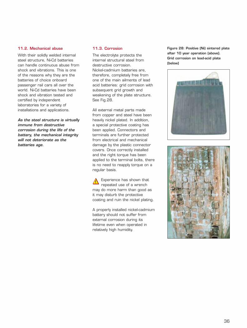
36
11.2. Mechanical abuse
With their solidly welded internalsteel structure, Ni-Cd batteriescan handle continuous abuse fromshock and vibrations. This is oneof the reasons why they are thebatteries of choice onboardpassenger rail cars all over theworld. Ni-Cd batteries have beenshock and vibration tested andcertified by independentlaboratories for a variety ofinstallations and applications.
As the steel structure is virtuallyimmune from destructivecorrosion during the life of thebattery, the mechanical integritywill not deteriorate as thebatteries age.
11.3. Corrosion
The electrolyte protects theinternal structural steel fromdestructive corrosion. Nickel-cadmium batteries are,therefore, completely free fromone of the main ailments of leadacid batteries: grid corrosion withsubsequent grid growth andweakening of the plate structure. See Fig.28.
All external metal parts madefrom copper and steel have beenheavily nickel plated. In addition, a special protective coating hasbeen applied. Connectors andterminals are further protectedfrom electrical and mechanicaldamage by the plastic connectorcovers. Once correctly installedand the right torque has beenapplied to the terminal bolts, thereis no need to reapply torque on aregular basis.
Experience has shown thatrepeated use of a wrench
may do more harm than good asit may disturb the protectivecoating and ruin the nickel plating.
A properly installed nickel-cadmiumbattery should not suffer fromexternal corrosion during itslifetime even when operated inrelatively high humidity.
Figure 28: Positive (Ni) sintered plateafter 10 year operation (above).Grid corrosion on lead-acid plate(below)
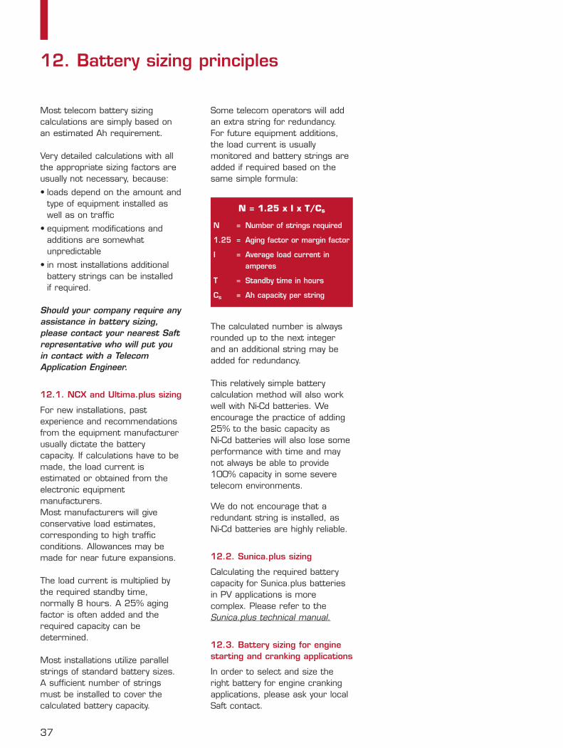
Most telecom battery sizingcalculations are simply based onan estimated Ah requirement.
Very detailed calculations with allthe appropriate sizing factors areusually not necessary, because:
• loads depend on the amount andtype of equipment installed aswell as on traffic
• equipment modifications andadditions are somewhatunpredictable
• in most installations additionalbattery strings can be installed if required.
Should your company require anyassistance in battery sizing, please contact your nearest Saftrepresentative who will put youin contact with a TelecomApplication Engineer.
12.1. NCX and Ultima.plus sizing
For new installations, pastexperience and recommendationsfrom the equipment manufacturerusually dictate the batterycapacity. If calculations have to bemade, the load current isestimated or obtained from theelectronic equipmentmanufacturers. Most manufacturers will giveconservative load estimates,corresponding to high trafficconditions. Allowances may bemade for near future expansions.
The load current is multiplied bythe required standby time,normally 8 hours. A 25% agingfactor is often added and therequired capacity can bedetermined.
Most installations utilize parallelstrings of standard battery sizes.A sufficient number of stringsmust be installed to cover thecalculated battery capacity.
Some telecom operators will addan extra string for redundancy.For future equipment additions,the load current is usuallymonitored and battery strings areadded if required based on thesame simple formula:
The calculated number is alwaysrounded up to the next integerand an additional string may beadded for redundancy.
This relatively simple batterycalculation method will also workwell with Ni-Cd batteries. Weencourage the practice of adding25% to the basic capacity as Ni-Cd batteries will also lose someperformance with time and maynot always be able to provide100% capacity in some severetelecom environments.
We do not encourage that aredundant string is installed, asNi-Cd batteries are highly reliable.
12.2. Sunica.plus sizing
Calculating the required batterycapacity for Sunica.plus batteriesin PV applications is morecomplex. Please refer to theSunica.plus technical manual.
12.3. Battery sizing for enginestarting and cranking applications
In order to select and size theright battery for engine crankingapplications, please ask your localSaft contact.
37
12. Battery sizing principles
N = 1.25 x I x T/Cs
N = Number of strings required
1.25 = Aging factor or margin factor
I = Average load current in amperes
T = Standby time in hours
Cs = Ah capacity per string
38
Ni-Cd batteries are designed foreasy installation, minimummaintenance and safe operation.
All batteries containhazardous materials and
energy that can cause damageand bodily harm if not handledproperly and correctly.
Therefore, before handling anytype of battery, make sure youhave a copy of an Installation andOperating Instruction Sheet foryour particular battery. Thereshould be an instruction sheetpacked with each battery. If it ismissing, contact your nearest Saftrepresentative and request a newinstruction sheet.
Familiarize yourself with thecontent of the I&O InstructionSheet before you handle thebattery and follow theinstructions step by step. Theinstructions will help you toinstall the battery efficiently andsafely and will allow you to obtainmaximum battery life andperformance at the lowestpossible cost.
13.1. Safety
The most important part of theinstructions is the section thatdeals with safety. Be aware of thepotential sources of hazards andlearn how to deal with them andunderstand what precautions arerequired. Here are a few basicpoints:
Corrosive electrolyteEye protection is a must as asmall splash of electrolyte
may cause permanent eyedamage. Electrolyte may alsocause skin irritation and ruinclothing unless washed offimmediately. Wear protection.
Explosive gassesHydrogen and oxygen aredeveloped during charging. The gas mixture inside the cellsshould always be considered highlyexplosive. Explosive mixtures ofhydrogen and air or oxygen mayalso accumulate inside batteryenclosures and rooms unlessgenerously ventilated.
Never smoke, use open flameor generate sparks near a
battery. Do not wear clothing thatgenerate static electricity anddischarge your body and your toolsto a grounded (earthed) metalobject before you work on abattery that has been charged.
Electrical shocks and burnsCare must be exercised to avoidelectric shocks, particularly fromhigh voltage batteries. Care andprecautions must be taken to avoidshort circuits from tools and othermetal objects such as jewelry.
Metal watchstraps and jewelrymust not be worn when
working on batteries. Read moreabout safety in the Installation andOperating Instructions.
13.2. Transportation and storage
The different types of Ni-Cdbatteries are transported andstored differently.
All S/PBE batteries such as NCXand SPH are shipped and storedfilled with electrolyte anddischarged. These batteries aremost stable and durable in thiscondition. They can be left instorage in this condition for severalyears. No commissioning charge isnecessary before installation.
PP batteries such as Ultima.plus,Sunica.plus and SBH types aregenerally shipped filled andcharged. They can be stored in
this condition for up to one year. If stored for more than 6 monthsbefore installation, it isrecommended that acommissioning charge should be made first.
Batteries are shipped andclassified as hazardous material.Some communities haveregulations regarding reportablequantities of hazardous materialsstored and installed. If you plana large battery installation, youshould check with your localenvironmental authorities or fireprotection department.
The storage area must bedry, clean and located
indoors. The plastic casing of thebatteries must be protected fromdirect sunlight.
13.3. Installation
Ni-Cd batteries should be installedin a dry and clean location, freefrom direct sunlight and heat. The battery compartment or roommust be well ventilated. Followapplicable safety standards forventilation. Batteries work best intemperatures between +10°C to+30°C (+50°F to +86°F). FollowSaft’s installation instructions.
13.4. Maintenance
Saft batteries are designed forminimum maintenance.
Simply follow the Installation andOperation Instructions that arewritten for your type of battery, asdifferent batteries and differentapplications have differentrequirements.If you find the maintenanceprocedures impractical or difficultto follow, consult a Saft TelecomApplication Engineer.
13. Installation and operation
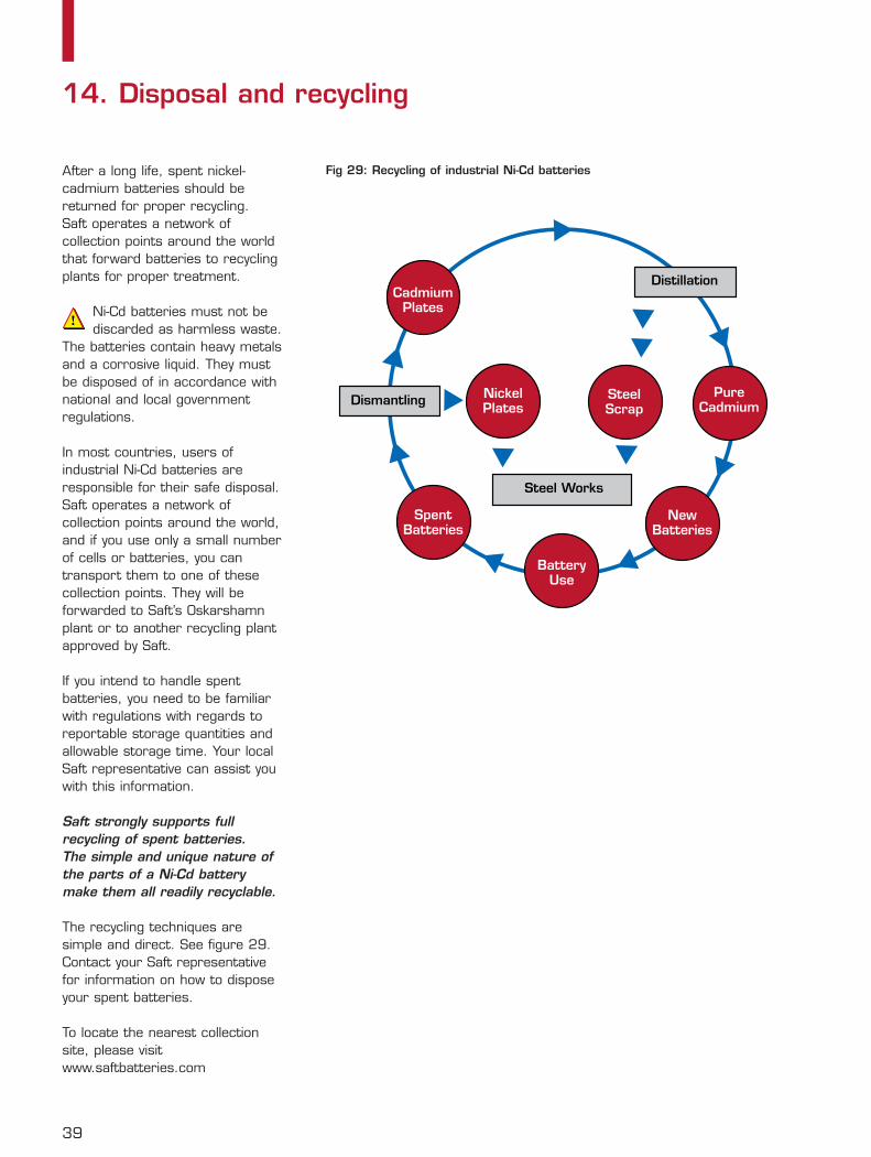
After a long life, spent nickel-cadmium batteries should bereturned for proper recycling. Saft operates a network ofcollection points around the worldthat forward batteries to recyclingplants for proper treatment.
Ni-Cd batteries must not bediscarded as harmless waste.
The batteries contain heavy metalsand a corrosive liquid. They mustbe disposed of in accordance withnational and local governmentregulations.
In most countries, users ofindustrial Ni-Cd batteries areresponsible for their safe disposal.Saft operates a network ofcollection points around the world,and if you use only a small numberof cells or batteries, you cantransport them to one of thesecollection points. They will beforwarded to Saft’s Oskarshamnplant or to another recycling plantapproved by Saft.
If you intend to handle spentbatteries, you need to be familiarwith regulations with regards toreportable storage quantities andallowable storage time. Your localSaft representative can assist youwith this information.
Saft strongly supports fullrecycling of spent batteries. The simple and unique nature ofthe parts of a Ni-Cd batterymake them all readily recyclable.
The recycling techniques aresimple and direct. See figure 29.Contact your Saft representativefor information on how to disposeyour spent batteries.
To locate the nearest collectionsite, please visitwww.saftbatteries.com
39
14. Disposal and recycling
BatteryUse
NewBatteries
PureCadmium
SpentBatteries
CadmiumPlates
Dismantling
Distillation
Steel Works
NickelPlates
SteelScrap
Fig 29: Recycling of industrial Ni-Cd batteries
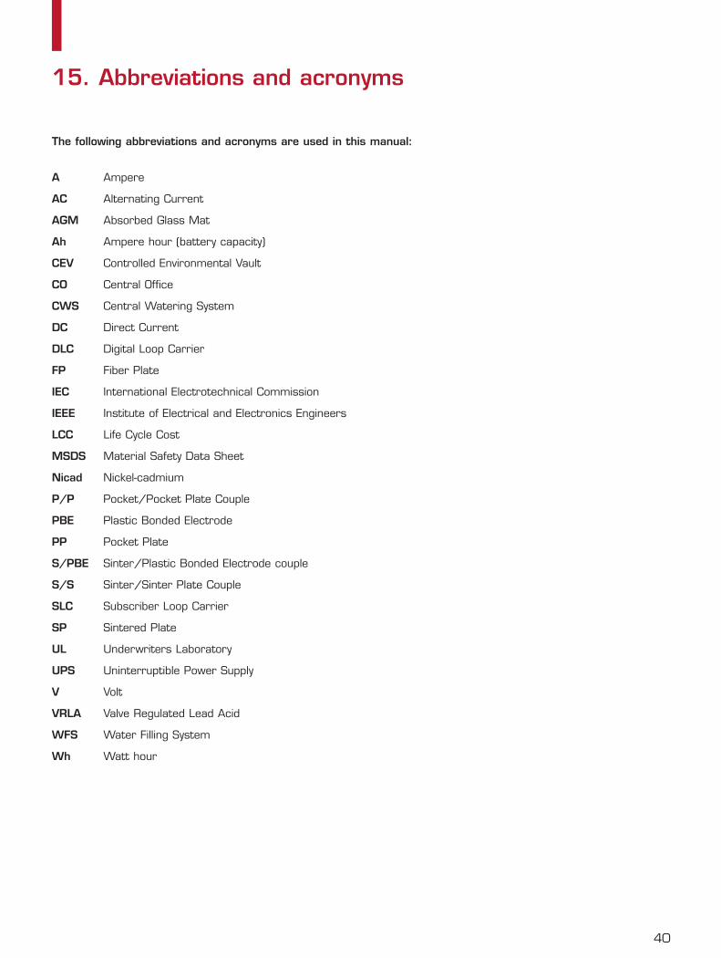
40
The following abbreviations and acronyms are used in this manual:
A Ampere
AC Alternating Current
AGM Absorbed Glass Mat
Ah Ampere hour (battery capacity)
CEV Controlled Environmental Vault
CO Central Office
CWS Central Watering System
DC Direct Current
DLC Digital Loop Carrier
FP Fiber Plate
IEC International Electrotechnical Commission
IEEE Institute of Electrical and Electronics Engineers
LCC Life Cycle Cost
MSDS Material Safety Data Sheet
Nicad Nickel-cadmium
P/P Pocket/Pocket Plate Couple
PBE Plastic Bonded Electrode
PP Pocket Plate
S/PBE Sinter/Plastic Bonded Electrode couple
S/S Sinter/Sinter Plate Couple
SLC Subscriber Loop Carrier
SP Sintered Plate
UL Underwriters Laboratory
UPS Uninterruptible Power Supply
V Volt
VRLA Valve Regulated Lead Acid
WFS Water Filling System
Wh Watt hour
15. Abbreviations and acronyms

41
Notes
SaftIndustrial Battery Group 12, rue Sadi Carnot 93170 Bagnolet - FranceTel: +33 1 49 93 19 18Fax: +33 1 49 93 19 64
www.saftbatteries.com
Doc N° 21092-2-0704Data in this document is subject to change withoutnotice and becomes contractual only after writtenconfirmation.
Société anonyme au capital de 31 944 000 €RCS Bobigny B 383 703 873
Pragma - Printed in France - 2k
GENERAL INQUIRIES
North AmericaValdosta (GA)tel +1 229 245 2854tel +1 800 308 9041fax +1 229 247 [email protected]
Rest of the worldBagnolet – Francetel +33 1 49 93 17 14fax +33 1 49 93 19 62
LOCAL CONTACTS
AfricaExport sales dpt, Francetel +33 1 49 93 19 18fax +33 1 49 93 19 56
Argentina Energia Alcalina, Buenos Airestel +54 11 4334 9034/35fax +54 11 4342 5024
AustraliaSaft Australia Pty Ltd, Seven Hillstel +61 2 9674 0700fax +61 2 9620 9990
AustriaStatron GmbH, Wientel +43 1 617 40 60fax +43 1 617 40 60/40
BelgiumAEG Belgium SA, Brusselstel +32 2 529 6543fax +32 2 529 6449
BrazilFSE (Fábrica de Sistemas de Energia Ltda.),tel +55 11 6100 6304fax +55 11 6100 6338
Canada Please contact USA office
ChileTechno Parts Ltda, Santiagotel +56 2 249 6060fax +56 2 249 6060
ChinaSaft Tradingtel +86 21 5866 7935fax +86 21 5866 6403
Czech RepublicSaft Ferak a.s., Praguetel +420 281 080 120fax +420 281 080 119
DenmarkScansupply A/S, Birkeroedtel +45 45 82 50 90fax +45 45 82 54 40
FinlandHansaBattery Oy, Espootel +358 9 260 65 292fax +358 9 260 65 299
FranceDivision France, Bagnolettel +33 1 49 93 19 18fax +33 1 49 93 19 56
GermanySaft Batterien GmbH, Nürnbergtel +49 911 94 174-0fax +49 911 426 144
Hong KongSaft Ltd, Kowloontel +852 2796 99 32fax +852 2798 06 19
India sub continentExport sales dpt, Swedentel +46 491 680 00fax +46 491 681 80
ItalySaft Batterie Italia S.r.l.tel +39 02 89 28 07 47fax +39 02 89 28 07 62
JapanSumitomo Corp., Tokyotel +81 3 5144 9082fax +81 3 5144 9267
KoreaEnergys Korea Co. Ltd, Kyunggi-Dotel +82 2501 0033fax +82 2501 0034
MexicoTroop y Compania, SA de CV, Mexicotel +52 55 50 82 10 30fax +52 55 50 82 10 39
Middle EastSaft Nife ME Ltd, Limassol, Cyprustel +357 25 820040fax +357 25 748492
NetherlandsSaft Batteries B.V., Haarlemtel +31 23 750 5720fax +31 23 750 5725
NorwaySaft AS, Osteraastel +47 6716 4160fax +47 6716 4170
RussiaZAO Alcatel, Moscowtel +7 095 937 0967fax +7 095 937 0906
SingaporeSaft Batteries Pte Ltd, Singaporetel +65 6512 1500fax +65 6749 7282
SpainSaft Baterias S.L.San Sebatian de los Reyestel +34 916 593 480fax +34 916 593 490
SwedenSaft AB, Oskarshamntel +46 491 680 00fax +46 491 681 80
SwitzerlandStatron GmbH, Mägenwilltel +41 62 887 4 887fax +41 62 887 4 888
United KingdomSaft Ltd, Harlowtel +44 1279 772 550fax +44 1279 420 909
USASaft America Inc.,Valdosta (GA)tel +1 229 245 2854tel +1 800 308 9041fax +1 229 247 8486
VenezuelaINTELEC S.A.,Caracastel +58 212 242 7473fax +58 212 241 6514
Committed to a clean environmentSaft takes seriously its responsibility to safeguard the environment. At several sites worldwide, more than 99% of metals contained in thebattery are recycled. This process safeguards valuable natural resources
and is a service to customers that Saft will continue to offer for future generations.To locate the nearest collection site, visit www.saftbatteries.com.