Embed Size (px)
Citation preview
Nickel Cadmium and Nickel-Metal Hydride Rechargeable Batteries and Chargers
Battery Features and Construction ............................................................ 1Batteries – Standard Range ....................................................................... 2NiCd Charging and Discharging Characteristics ...................................3-4NiMH Charging and Discharging Characteristics ..................................4-5NiCd and NiMH Charging Method .............................................................. 6Cell Assemblies ............................................................................................ 7Important Do’s and Don’ts .................................................................... 8-10Recycling ..................................................................................................... 10Differences Between NiCd and NiMH Batteries .................................... 10NiCd and NiMH Cell Profiles ............................................................... 11-12PSN-Series Charger Specifications ..........................................................13
Table of Contents
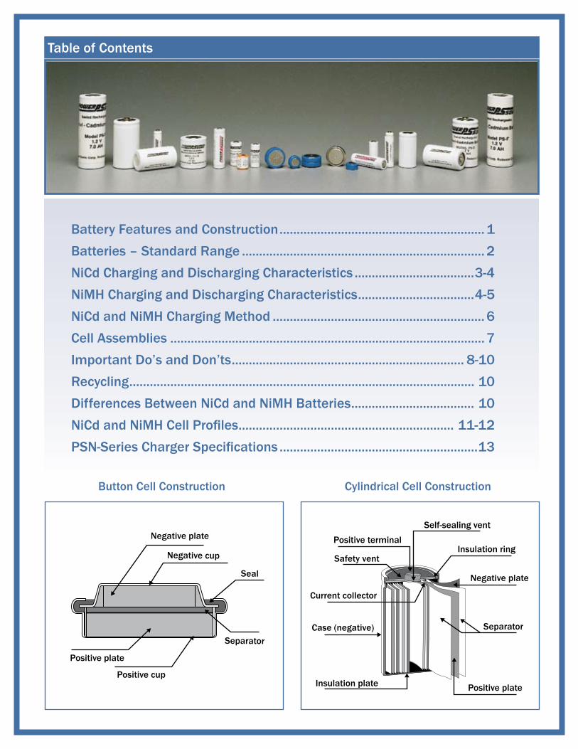
Button Cell Construction
Negative plate
Positive plate
Positive cup
Negative cup
Seal
Separator
Cylindrical Cell Construction
Positive terminal
Self-sealing vent
Insulation ring
Negative plate
Separator
Positive plateInsulation plate
Case (negative)
Current collector
Safety vent
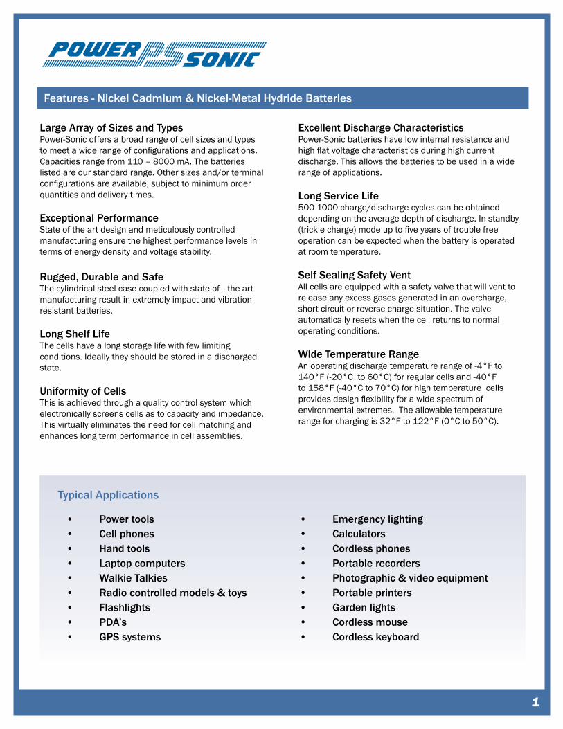
Large Array of Sizes and TypesPower-Sonic offers a broad range of cell sizes and types to meet a wide range of configurations and applications. Capacities range from 110 – 8000 mA. The batteries listed are our standard range. Other sizes and/or terminal configurations are available, subject to minimum order quantities and delivery times.
Exceptional PerformanceState of the art design and meticulously controlled manufacturing ensure the highest performance levels in terms of energy density and voltage stability.
Rugged, Durable and SafeThe cylindrical steel case coupled with state-of –the art manufacturing result in extremely impact and vibration resistant batteries.
Long Shelf LifeThe cells have a long storage life with few limiting conditions. Ideally they should be stored in a discharged state.
Uniformity of CellsThis is achieved through a quality control system which electronically screens cells as to capacity and impedance. This virtually eliminates the need for cell matching and enhances long term performance in cell assemblies.
Excellent Discharge CharacteristicsPower-Sonic batteries have low internal resistance and high flat voltage characteristics during high current discharge. This allows the batteries to be used in a wide range of applications.
Long Service Life500-1000 charge/discharge cycles can be obtained depending on the average depth of discharge. In standby (trickle charge) mode up to five years of trouble free operation can be expected when the battery is operated at room temperature.
Self Sealing Safety VentAll cells are equipped with a safety valve that will vent to release any excess gases generated in an overcharge, short circuit or reverse charge situation. The valve automatically resets when the cell returns to normal operating conditions.
Wide Temperature RangeAn operating discharge temperature range of -4°F to 140°F (-20°C to 60°C) for regular cells and -40°F to 158°F (-40°C to 70°C) for high temperature cells provides design flexibility for a wide spectrum of environmental extremes. The allowable temperature range for charging is 32°F to 122°F (0°C to 50°C).
�
Features - Nickel Cadmium & Nickel-Metal Hydride Batteries
• Power tools• Cell phones• Hand tools• Laptop computers• Walkie Talkies• Radio controlled models & toys• Flashlights• PDA’s• GPS systems
• Emergency lighting• Calculators• Cordless phones• Portable recorders• Photographic & video equipment• Portable printers• Garden lights• Cordless mouse• Cordless keyboard
Typical Applications
Nickel Cadmium & Nickel-Metal Hydride Batteries
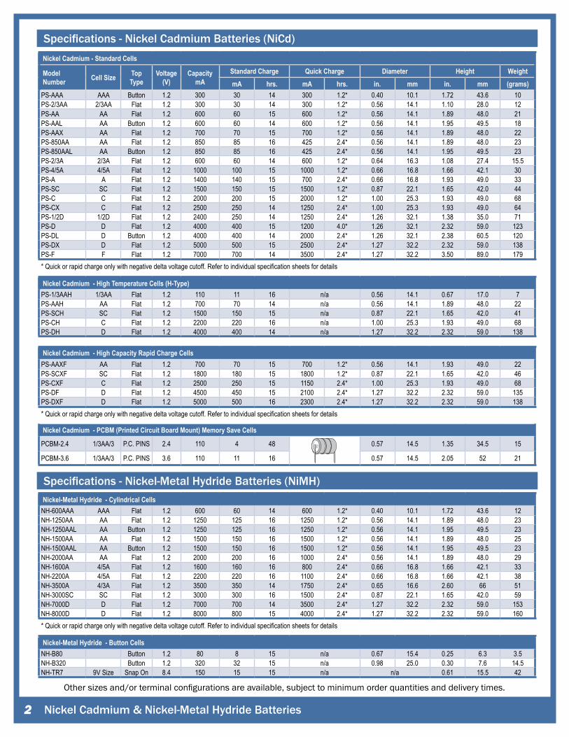
Specifications - Nickel Cadmium Batteries (NiCd)
�
Other sizes and/or terminal configurations are available, subject to minimum order quantities and delivery times.
Nickel Cadmium - Standard Cells
Model Number Cell Size Top
TypeVoltage
(V)Capacity
mAStandard Charge Quick Charge Diameter Height WeightmA hrs. mA hrs. in. mm in. mm (grams)
PS-AAA AAA Button 1.2 300 30 14 300 1.2* 0.40 10.1 1.72 43.6 10PS-2/3AA 2/3AA Flat 1.2 300 30 14 300 1.2* 0.56 14.1 1.10 28.0 12PS-AA AA Flat 1.2 600 60 15 600 1.2* 0.56 14.1 1.89 48.0 21PS-AAL AA Button 1.2 600 60 14 600 1.2* 0.56 14.1 1.95 49.5 18PS-AAX AA Flat 1.2 700 70 15 700 1.2* 0.56 14.1 1.89 48.0 22PS-850AA AA Flat 1.2 850 85 16 425 2.4* 0.56 14.1 1.89 48.0 23PS-850AAL AA Button 1.2 850 85 16 425 2.4* 0.56 14.1 1.95 49.5 23PS-2/3A 2/3A Flat 1.2 600 60 14 600 1.2* 0.64 16.3 1.08 27.4 15.5PS-4/5A 4/5A Flat 1.2 1000 100 15 1000 1.2* 0.66 16.8 1.66 42.1 30PS-A A Flat 1.2 1400 140 15 700 2.4* 0.66 16.8 1.93 49.0 33PS-SC SC Flat 1.2 1500 150 15 1500 1.2* 0.87 22.1 1.65 42.0 44PS-C C Flat 1.2 2000 200 15 2000 1.2* 1.00 25.3 1.93 49.0 68PS-CX C Flat 1.2 2500 250 14 1250 2.4* 1.00 25.3 1.93 49.0 64PS-1/2D 1/2D Flat 1.2 2400 250 14 1250 2.4* 1.26 32.1 1.38 35.0 71PS-D D Flat 1.2 4000 400 15 1200 4.0* 1.26 32.1 2.32 59.0 123PS-DL D Button 1.2 4000 400 14 2000 2.4* 1.26 32.1 2.38 60.5 120PS-DX D Flat 1.2 5000 500 15 2500 2.4* 1.27 32.2 2.32 59.0 138PS-F F Flat 1.2 7000 700 14 3500 2.4* 1.27 32.2 3.50 89.0 179* Quick or rapid charge only with negative delta voltage cutoff. Refer to individual specification sheets for details
Nickel Cadmium - PCBM (Printed Circuit Board Mount) Memory Save Cells
PCBM-2.4 1/3AA/3 P.C. PINS 2.4 110 4 48 0.57 14.5 1.35 34.5 15
PCBM-3.6 1/3AA/3 P.C. PINS 3.6 110 11 16 0.57 14.5 2.05 52 21
Nickel Cadmium - High Temperature Cells (H-Type)PS-1/3AAH 1/3AA Flat 1.2 110 11 16 n/a 0.56 14.1 0.67 17.0 7PS-AAH AA Flat 1.2 700 70 14 n/a 0.56 14.1 1.89 48.0 22PS-SCH SC Flat 1.2 1500 150 15 n/a 0.87 22.1 1.65 42.0 41PS-CH C Flat 1.2 2200 220 16 n/a 1.00 25.3 1.93 49.0 68PS-DH D Flat 1.2 4000 400 14 n/a 1.27 32.2 2.32 59.0 138
Nickel Cadmium - High Capacity Rapid Charge CellsPS-AAXF AA Flat 1.2 700 70 15 700 1.2* 0.56 14.1 1.93 49.0 22PS-SCXF SC Flat 1.2 1800 180 15 1800 1.2* 0.87 22.1 1.65 42.0 46PS-CXF C Flat 1.2 2500 250 15 1150 2.4* 1.00 25.3 1.93 49.0 68PS-DF D Flat 1.2 4500 450 15 2100 2.4* 1.27 32.2 2.32 59.0 135PS-DXF D Flat 1.2 5000 500 16 2300 2.4* 1.27 32.2 2.32 59.0 138* Quick or rapid charge only with negative delta voltage cutoff. Refer to individual specification sheets for details
Nickel-Metal Hydride - Cylindrical CellsNH-600AAA AAA Flat 1.2 600 60 14 600 1.2* 0.40 10.1 1.72 43.6 12NH-1250AA AA Flat 1.2 1250 125 16 1250 1.2* 0.56 14.1 1.89 48.0 23NH-1250AAL AA Button 1.2 1250 125 16 1250 1.2* 0.56 14.1 1.95 49.5 23NH-1500AA AA Flat 1.2 1500 150 16 1500 1.2* 0.56 14.1 1.89 48.0 25NH-1500AAL AA Button 1.2 1500 150 16 1500 1.2* 0.56 14.1 1.95 49.5 23NH-2000AA AA Flat 1.2 2000 200 16 1000 2.4* 0.56 14.1 1.89 48.0 29NH-1600A 4/5A Flat 1.2 1600 160 16 800 2.4* 0.66 16.8 1.66 42.1 33NH-2200A 4/5A Flat 1.2 2200 220 16 1100 2.4* 0.66 16.8 1.66 42.1 38NH-3500A 4/3A Flat 1.2 3500 350 14 1750 2.4* 0.65 16.6 2.60 66 51NH-3000SC SC Flat 1.2 3000 300 16 1500 2.4* 0.87 22.1 1.65 42.0 59NH-7000D D Flat 1.2 7000 700 14 3500 2.4* 1.27 32.2 2.32 59.0 153NH-8000D D Flat 1.2 8000 800 15 4000 2.4* 1.27 32.2 2.32 59.0 160* Quick or rapid charge only with negative delta voltage cutoff. Refer to individual specification sheets for details
Nickel-Metal Hydride - Button CellsNH-B80 Button 1.2 80 8 15 n/a 0.67 15.4 0.25 6.3 3.5NH-B320 Button 1.2 320 32 15 n/a 0.98 25.0 0.30 7.6 14.5NH-TR7 9V Size Snap On 8.4 150 15 15 n/a n/a 0.61 15.5 42
Specifications - Nickel-Metal Hydride Batteries (NiMH)
Time (min.)
Volta
ge (V
)
1.7
1.6
1.5
1.4
1.3
1.2
1.1100 20 30 40 50 60 70 80 90
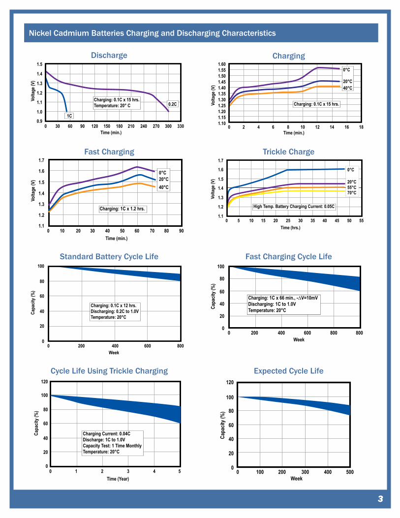
Charging: 1C x 1.2 hrs.
0°C20°C40°C
Time (hrs.)
Volta
ge (V
)
1.7
1.6
1.5
1.4
1.3
1.2
1.150 10 15 20 25 30 35 40 45 50 55
High Temp. Battery Charging Current: 0.05C
0°C
20°C55°C70°C
Week
Capa
city (
%)
100
80
60
40
20
00 200 400 600 800
Charging: 0.1C x 12 hrs.Discharging: 0.2C to 1.0VTemperature: 20°C
Week
Capa
city (
%)
100
80
60
40
20
00 200 400 600 800 800
Charging: 1C x 66 min., -∆V=10mVDischarging: 1C to 1.0VTemperature: 20°C
1.5
0 30 60 90 120 150 180 210 240 270 300 330Time (min.)
Volta
ge (V
)
1.4
1.3
1.2
1.1
1.0
0.9
Charging: 0.1C x 15 hrs.Temperature: 20° C 0.2C
1C
Time (min.)
Volta
ge (V
)
1.601.551.501.451.401.351.301.251.201.151.10
0 2 4 6 8 10 12 14 16 18
Charging: 0.1C x 15 hrs.
0°C
20°C40°C
Nickel Cadmium Batteries Charging and Discharging Characteristics
Discharge Charging
Fast Charging Trickle Charge
Standard Battery Cycle Life Fast Charging Cycle Life
�
Cycle Life Using Trickle Charging Expected Cycle Life
Time (Year)
Capa
city (
%)
120
100
80
60
40
20
00 1 2 3 4 5
Charging Current: 0.04CDischarge: 1C to 1.0VCapacity Test: 1 Time MonthlyTemperature: 20°C
Week
Capa
city (
%)
120
100
80
60
40
20
00 100 200 300 400 500

Number of Cycles
Disc
harg
e Cap
acity
120100
80
60
40
20
01000 200 300 400 500
Charge: 0.5C to 2.2 hrs. or -∆ Cut-offDischarge: 0.2C to 1.0VAmbient Temperature: 20°C
Capacity Input (%)
Volta
ge (V
)
1.6
1.5
1.4
1.3
1.2
1.1200 40 60 80 100 120 140 160
0.1C0.05C
1C
Storage Time (Days)
Reta
ined
Cap
acity
(%)
110100
908070605040302010
0 200 40 60 80 100
0°C
20°C
40°C
Time (Month)
Tem
pera
ture
(°C)
605040302010
00 5 10 15 20 25 30 35 40 45 50 55 60 65
Temperature (°C)
Capa
city R
atio
(%)
120
100
80
60
40
20
-10 0 10 20 30 40 50 60 700
Charging: 0.05C x 48 hrs.Discharge: 0.2C, Cut-off voltage: 1.0V
Standard Cell
High Temperature Cell
Nickel Cadmium Batteries Charging and Discharging Characteristics
Stand-by Battery Life Capacity vs Temperature
Retained Capacity in Storage
Nickel Cadmium & Nickel-Metal Hydride Batteries�
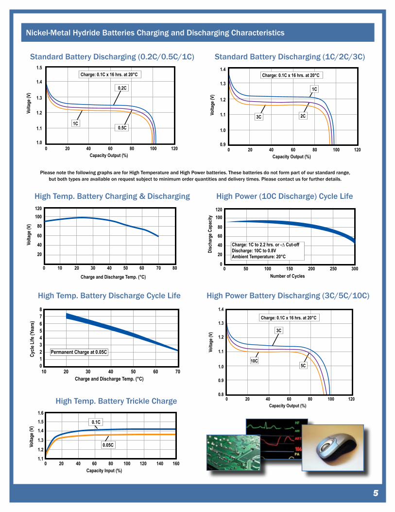
Nickel-Metal Hydride Batteries Charging and Discharging Characteristics
Standard Battery Discharge Cycle Life Standard Battery Charging
Charge and Discharge Temp. (°C)
Cycle
Life
(Yea
rs)
87654321010 20 30 40 50 60 70
Permanent Charge at 0.05C
Charge and Discharge Temp. (°C)
Volta
ge (V
)
120100
80
60
40
20
100 20 30 40 50 60 70 80
Capacity Input (%)
Volta
ge (V
)
1.61.5
1.4
1.3
1.2
1.1200 40 60 80 100 120 140 160
0.1C
0.05C
Nickel-Metal Hydride Batteries Charging and Discharging Characteristics
High Temp. Battery Discharge Cycle Life
High Temp. Battery Charging & Discharging
�
Standard Battery Discharging (0.2C/0.5C/1C) Standard Battery Discharging (1C/2C/3C)
Capacity Output (%)
Volta
ge (V
)
1.5
1.4
1.3
1.2
1.1
1.0200 40 60 80 100 120
0.2C
0.5C
Charge: 0.1C x 16 hrs. at 20°C
1C
Capacity Output (%)
Volta
ge (V
)
1.4
1.3
1.2
1.1
1.0
0.9200 40 60 80 100 120
Charge: 0.1C x 16 hrs. at 20°C
1C
2C3C
Please note the following graphs are for High Temperature and High Power batteries. These batteries do not form part of our standard range, but both types are available on request subject to minimum order quantities and delivery times. Please contact us for further details.
High Temp. Battery Trickle Charge
Number of Cycles
Disc
harg
e Cap
acity
120100
80
60
40
20
0500 100 150 200 250 300
Charge: 1C to 2.2 hrs. or -∆ Cut-offDischarge: 10C to 0.8VAmbient Temperature: 20°C
High Power (10C Discharge) Cycle Life
High Power Battery Discharging (3C/5C/10C)
Capacity Output (%)
Volta
ge (V
)
1.4
1.3
1.2
1.1
1.0
0.9
0.8200 40 60 80 100 120
Charge: 0.1C x 16 hrs. at 20°C
10C5C
3C
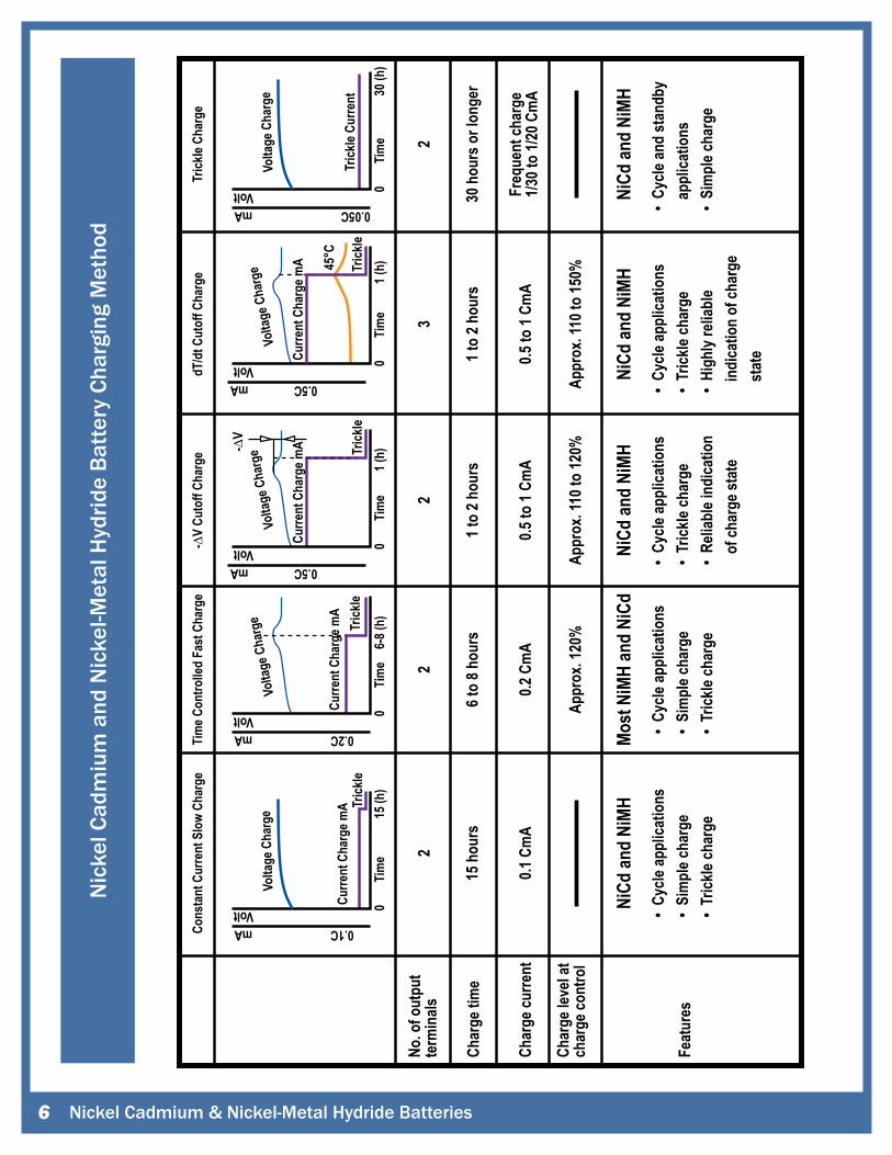
Nic
kel C
adm
ium
and
Nic
kel-M
etal
Hyd
ride
Batte
ry C
harg
ing
Met
hod
No. o
f out
put
term
inals
2
15 h
ours
Cons
tant
Cur
rent
Slo
w Ch
arge
Tim
e Con
trolle
d Fa
st C
harg
eTr
ickle
Char
gedT
/dt C
utof
f Cha
rge
-∆V
Cuto
ff Ch
arge
0.1 C
mA
NiCd
and
NiMH
NiCd
and
NiMH
Most
NiM
H an
d Ni
CdNi
Cd an
d Ni
MHNi
Cd an
d Ni
MH
6 to
8 hou
rs
0.2 C
mA
Appr
ox. 1
20%
Appr
ox. 1
10 to
120%
Appr
ox. 1
10 to
150%
1 to
2 hou
rs
0.5 to
1 Cm
A
1 to
2 hou
rs
0.5 to
1 Cm
A
30 h
ours
or l
onge
r
Freq
uent
char
ge1/3
0 to
1/20 C
mA
22
32
Char
ge ti
me
Char
ge cu
rrent
Feat
ures
• Cy
cle ap
plica
tions
• Si
mpl
e cha
rge
• Tr
ickle
char
ge
• Cy
cle ap
plica
tions
• Si
mpl
e cha
rge
• Tr
ickle
char
ge
• Cy
cle ap
plica
tions
• Tr
ickle
char
ge•
Relia
ble i
ndica
tion
of c
harg
e sta
te
• Cy
cle ap
plica
tions
• Tr
ickle
char
ge•
High
ly re
liabl
e i
ndica
tion
of ch
arge
sta
te
• Cy
cle an
d st
andb
y a
pplic
atio
ns•
Sim
ple c
harg
e
Char
ge le
vel a
tch
arge
cont
rol
Trick
le
Tim
e
VoltmA 0.2C
06-
8 (h)
Curre
nt C
harg
e mA
Volta
ge C
harg
e
Trick
le
-∆V
Tim
e
VoltmA 0.5C
01 (
h)
Curre
nt C
harg
e mA
Volta
ge C
harg
e
Trick
le
45°C
Tim
e
VoltmA 0.5C
01 (
h)
Curre
nt C
harg
e mA
Volta
ge C
harg
e
Trick
leTi
me
VoltmA 0.1C
015
(h)
Curre
nt C
harg
e mA
Volta
ge C
harg
e
Tim
e
VoltmA 0.05C
030
(h)
Trick
le Cu
rrent
Volta
ge C
harg
e
Nickel Cadmium & Nickel-Metal Hydride Batteries�
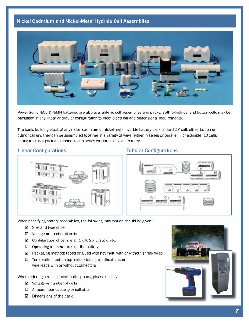
Nickel Cadmium and Nickel-Metal Hydride Cell Assemblies
Power-Sonic NiCd & NiMH batteries are also available as cell assemblies and packs. Both cylindrical and button cells may be packaged in any linear or tubular configuration to meet electrical and dimensional requirements.
The basic building block of any nickel cadmium or nickel-metal hydride battery pack is the 1.2V cell, either button or cylindrical and they can be assembled together in a variety of ways, either in series or parallel. For example, 10 cells configured as a pack and connected in series will form a 12 volt battery.
When specifying battery assemblies, the following information should be given:Size and type of cellVoltage or number of cellsConfiguration of cells: e.g., 1 x 4, 2 x 5, stick, etc.Operating temperatures for the batteryPackaging method: taped or glued with hot melt; with or without shrink wrap Termination: button top, solder tabs (incl. direction), or wire leads with or without connectors
When ordering a replacement battery pack, please specify:Voltage or number of cells Ampere-hour capacity or cell sizeDimensions of the pack
Linear Configurations Tubular Configurations
�
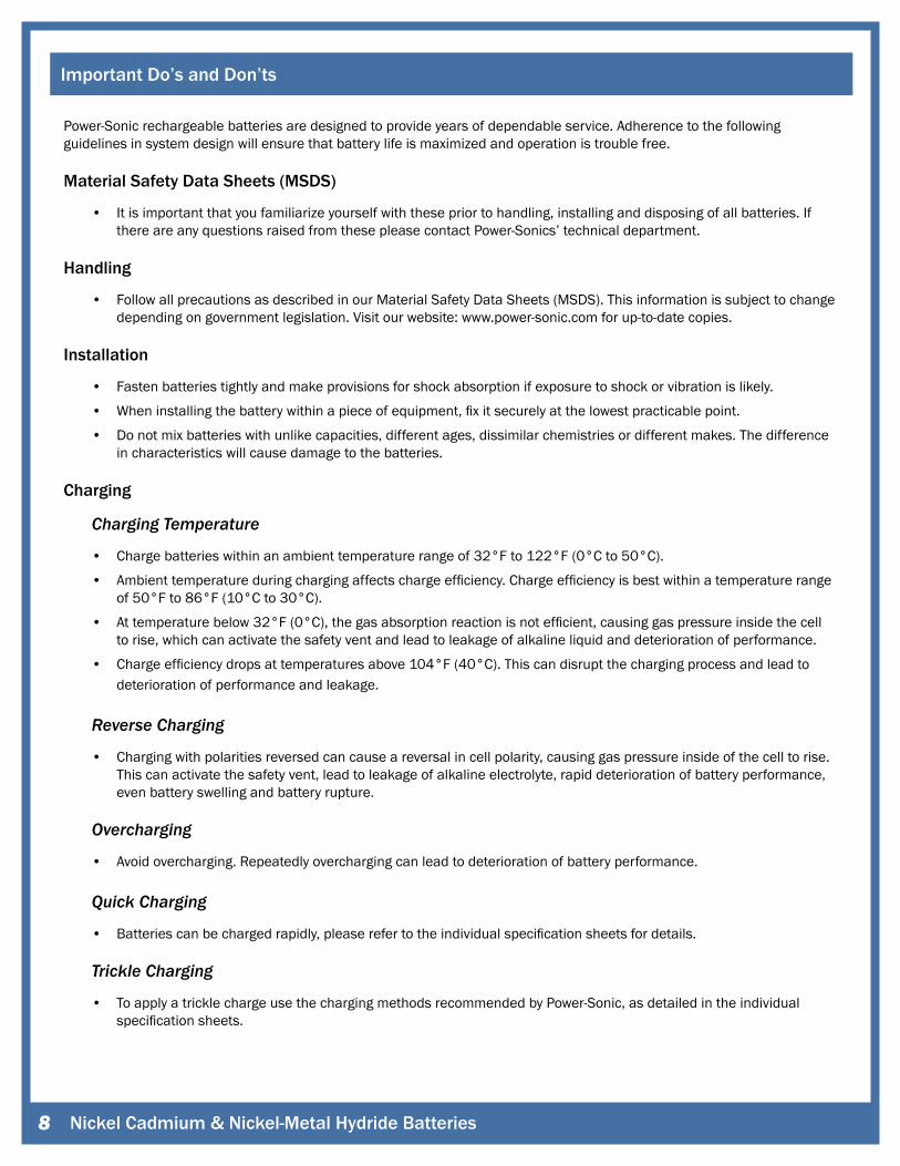
Power-Sonic rechargeable batteries are designed to provide years of dependable service. Adherence to the following guidelines in system design will ensure that battery life is maximized and operation is trouble free.
Material Safety Data Sheets (MSDS)
• It is important that you familiarize yourself with these prior to handling, installing and disposing of all batteries. If there are any questions raised from these please contact Power-Sonics’ technical department.
Handling
• Follow all precautions as described in our Material Safety Data Sheets (MSDS). This information is subject to change depending on government legislation. Visit our website: www.power-sonic.com for up-to-date copies.
Installation
• Fasten batteries tightly and make provisions for shock absorption if exposure to shock or vibration is likely.
• When installing the battery within a piece of equipment, fix it securely at the lowest practicable point.
• Do not mix batteries with unlike capacities, different ages, dissimilar chemistries or different makes. The difference in characteristics will cause damage to the batteries.
Charging
ChargingTemperature
• Charge batteries within an ambient temperature range of 32°F to 122°F (0°C to 50°C).
• Ambient temperature during charging affects charge efficiency. Charge efficiency is best within a temperature range of 50°F to 86°F (10°C to 30°C).
• At temperature below 32°F (0°C), the gas absorption reaction is not efficient, causing gas pressure inside the cell to rise, which can activate the safety vent and lead to leakage of alkaline liquid and deterioration of performance.
• Charge efficiency drops at temperatures above 104°F (40°C). This can disrupt the charging process and lead to deterioration of performance and leakage.
ReverseCharging
• Charging with polarities reversed can cause a reversal in cell polarity, causing gas pressure inside of the cell to rise. This can activate the safety vent, lead to leakage of alkaline electrolyte, rapid deterioration of battery performance, even battery swelling and battery rupture.
Overcharging
• Avoid overcharging. Repeatedly overcharging can lead to deterioration of battery performance.
QuickCharging
• Batteries can be charged rapidly, please refer to the individual specification sheets for details.
TrickleCharging
• To apply a trickle charge use the charging methods recommended by Power-Sonic, as detailed in the individual specification sheets.
Important Do’s and Don’ts
Nickel Cadmium & Nickel-Metal Hydride Batteries�

Important Do’s and Don’ts
Discharging
DischargeTemperatures • Discharge batteries within an ambient temperature range of: Nickel Cadmium -4°F to 149°F (-20°C to 65°C ),
Nickel-Metal Hydride 14°F to 122°F (-10°C to 50°C)
• Discharge capacity will drop when the battery is discharged outside the ambient temperature range
Over-Discharging • Over-discharging damages the batteries performance. Full discharge has been reached when the the voltage drops
to 0.9V to 1.0V, see the individual specification sheets for the applicable details. When the battery has been fully discharged It should be disconnected from the equipment circuit.
StorageTemperatureandHumidity(short-term) • Store in a dry location with low humidity (Max.85%), within a temperature range of -4°F to 113°F (-20°C to 45°C)
Long-termStorage
• Store within temperature ranges between 50°F to 86°F (10°C to 30°C).
• When charging for the first time after long-term storage, deactivation of the batteries’ chemicals may have led to decreased battery capacity. Restore such batteries to original performance through repeating several cycles of charging and discharging.
CycleLife
• Significantly reduced discharge time, in spite of proper charging, means that the life of the battery has been exceeded. Also, at the end of service life, an unusual increase in internal resistance, or an internal short-circuit failure may occur.
ServiceLifeinStandbyOperation
• Normally, a battery will last 3 to 5 years if used under proper conditions. However, failure to satisfy conditions concerning charging, discharging, temperature and other factors during actual use can lead to shortened battery life.
Assembly And Design Considerations
ConnectingBatteriestoProducts • Never solder a lead wire or other connecting materials directly to the battery. Doing so will damage the battery’s
internal safety vent, separator, and other materials.
• To connect a battery spot-weld a tab made of nickel or nickel-plated steel to the battery’s terminal strip, then solder a lead wire to the tab.
• Use caution when disconnecting batteries from the equipment. MaterialforTerminalsinProductsUsingtheBatteries
• Small amounts of alkaline electrolyte can leak out from the battery seal during a period of extended use or when the safety vent is activated during improper use, use a highly alkaline-resistant material for a product’s contact terminals to avoid problems due to corrosion.
�
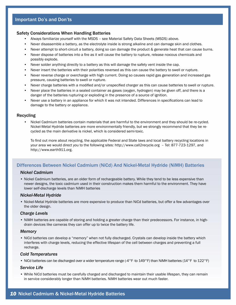
Safety Considerations When Handling Batteries • Always familiarize yourself with the MSDS – see Material Safety Data Sheets (MSDS) above. • Never disassemble a battery, as the electrolyte inside is strong alkaline and can damage skin and clothes. • Never attempt to short-circuit a battery, doing so can damage the product & generate heat that can cause burns. • Never dispose of batteries into a fire as it will cause the battery to rupture, release noxious chemicals and
possibly explode. • Never solder anything directly to a battery as this will damage the safety vent inside the cap. • Never insert the batteries with their polarities reversed as this can cause the battery to swell or rupture. • Never reverse charge or overcharge with high current. Doing so causes rapid gas generation and increased gas
pressure, causing batteries to swell or rupture. • Never charge batteries with a modified and/or unspecified charger as this can cause batteries to swell or rupture. • Never place the batteries in a sealed container as gases (oxygen, hydrogen) may be given off, and there is a
danger of the batteries rupturing or exploding in the presence of a source of ignition. • Never use a battery in an appliance for which it was not intended. Differences in specifications can lead to
damage to the battery or appliance.
Recycling • Nickel Cadmium batteries contain materials that are harmful to the environment and they should be re-cycled.
Nickel-Metal Hydride batteries are more environmentally friendly, but we strongly recommend that they be re-cycled as the main derivative is nickel, which is considered semi-toxic. To find out more about recycling, the applicable Federal and State laws and local battery recycling locations in your area we would direct you to the following sites: http://www.call2recycle.org – Tel: 877-723-1297, and http://www.earth911.org.
Differences Between Nickel Cadmium (NiCd) And Nickel-Metal Hydride (NiMH) Batteries NickelCadmium • Nickel Cadmium batteries, are an older form of rechargeable battery. While they tend to be less expensive than
newer designs, the toxic cadmium used in their construction makes them harmful to the environment. They have lower self-discharge levels than NiMH batteries
Nickel-MetalHydride • Nickel-Metal Hydride batteries are more expensive to produce than NiCd batteries, but offer a few advantages over
the older design.
ChargeLevels • NiMH batteries are capable of storing and holding a greater charge than their predecessors. For instance, in high-
drain devices like cameras they can offer up to twice the battery life.
Memory • NiCd batteries can develop a “memory” when not fully discharged. Crystals can develop inside the battery which
interferes with charge levels, reducing the effective lifespan of the cell between charges and preventing a full recharge.
ColdTemperatures • NiCd batteries can be discharged over a wider temperature range (-4°F -to 149°F) than NiMH batteries (14°F to 122°F)
ServiceLife • While NiCd batteries must be carefully charged and discharged to maintain their usable lifespan, they can remain
in service considerably longer than NiMH batteries. NiMH batteries wear out much faster.
Important Do’s and Don’ts
Nickel Cadmium & Nickel-Metal Hydride Batteries�0
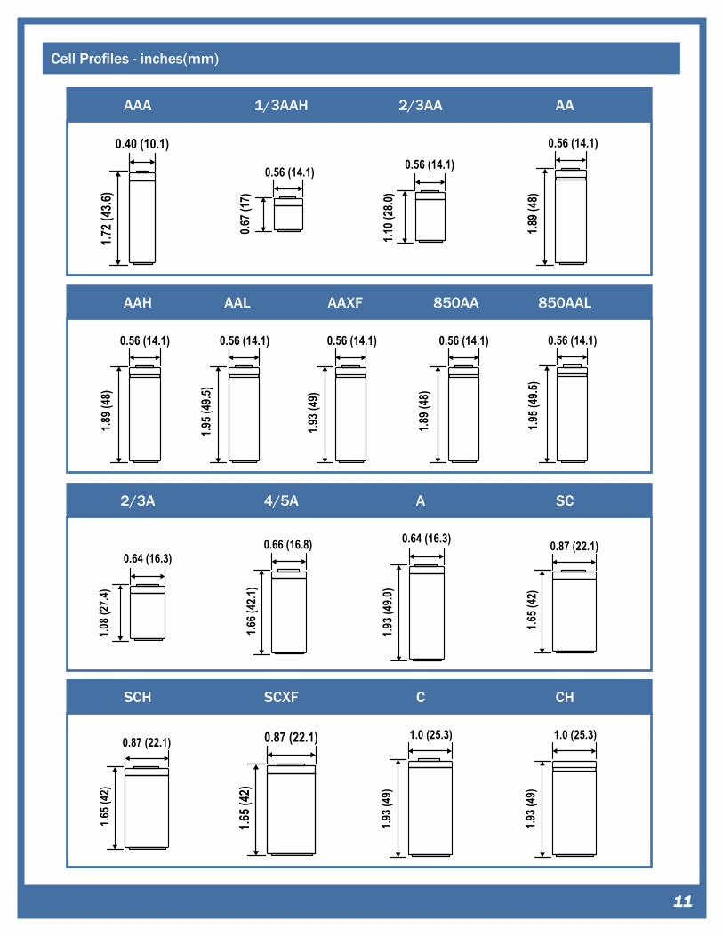
Cell Profiles - inches(mm)
��
0.40 (10.1)
1.72 (
43.6)
AAA 1/3AAH 2/3AA AA
0.56 (14.1)
0.67 (
17)
0.56 (14.1)
1.10 (
28.0)
0.56 (14.1)
1.89 (
48)
0.56 (14.1)
1.89 (
48)
AAH AAL AAXF 850AA
0.56 (14.1)
1.95 (
49.5)
0.56 (14.1)
1.93 (
49)
0.56 (14.1)
1.89 (
48)
0.56 (14.1)
1.95 (
49.5)
850AAL
2/3A 4/5A
0.64 (16.3)
1.08 (
27.4)
0.66 (16.8)
1.66 (
42.1)
SC
SCH
0.87 (22.1)1.6
5 (42
)
1.65 (
42)
0.87 (22.1)
0.64 (16.3)
1.93 (
49.0)
A
0.87 (22.1)
1.65 (
42)
SCXF C
1.0 (25.3)
1.93 (
49)
1.0 (25.3)
1.93 (
49)
CH
Nickel Cadmium & Nickel-Metal Hydride Batteries��
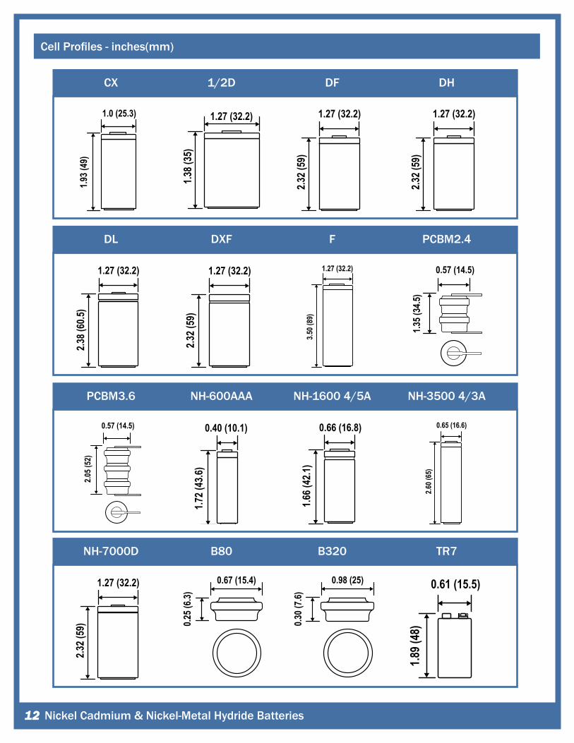
Cell Profiles - inches(mm)
1/2D DF
1.27 (32.2)
1.38 (
35)
1.27 (32.2)
2.32 (
59)
1.27 (32.2)
2.32 (
59)
1.27 (32.2)
2.38 (
60.5)
DXF F
1.27 (32.2)
2.32 (
59)
1.27 (32.2)
3.50 (
89)
0.40 (10.1)
1.72 (
43.6)
NH-600AAA NH-1600 4/5A
0.66 (16.8)
1.66 (
42.1)
0.67 (15.4)
0.25 (
6.3)
B80 B320 TR7
0.98 (25)
0.30 (
7.6) 0.61 (15.5)
1.89 (
48)
CX
1.0 (25.3)
1.93 (
49)
DH
DL PCBM2.4
0.57 (14.5)
1.35 (
34.5)
0.57 (14.5)
2.05 (
52)
PCBM3.6 NH-3500 4/3A
NH-7000D
0.65 (16.6)2.6
0 (65
)
1.27 (32.2)
2.32 (
59)
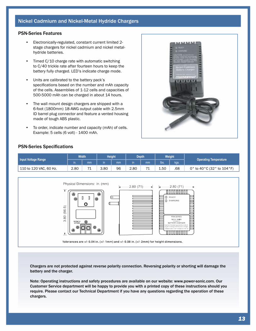
Nickel Cadmium and Nickel-Metal Hydride Chargers
PSN-Series Features
Electronically-regulated, constant current limited 2-stage chargers for nickel cadmium and nickel metal-hydride batteries.
Timed C/10 charge rate with automatic switching to C/40 trickle rate after fourteen hours to keep the battery fully charged. LED’s indicate charge mode.
Units are calibrated to the battery pack’s specifications based on the number and mAh capacity of the cells. Assemblies of 1-12 cells and capacities of 500-5000 mAh can be charged in about 14 hours.
The wall mount design chargers are shipped with a 6-foot (1800mm) 18-AWG output cable with 2.5mm ID barrel plug connector and feature a vented housing made of tough ABS plastic.
To order, indicate number and capacity (mAh) of cells. Example: 5 cells (6 volt) - 1400 mAh.
•
•
•
•
•
PSN-Series Specifications
Input Voltage RangeWidth Height Depth Weight
Operating Temperaturein. mm in mm in mm lbs. kgs.
110 to 120 VAC, 60 Hz. 2.80 71 3.80 96 2.80 71 1.50 .68 0° to 40°C (32° to 104°F)
Chargers are not protected against reverse polarity connection. Reversing polarity or shorting will damage the battery and the charger.
Note: Operating instructions and safety procedures are available on our website: www.power-sonic.com. Our Customer Service department will be happy to provide you with a printed copy of these instructions should you require. Please contact our Technical Department if you have any questions regarding the operation of these chargers.
��
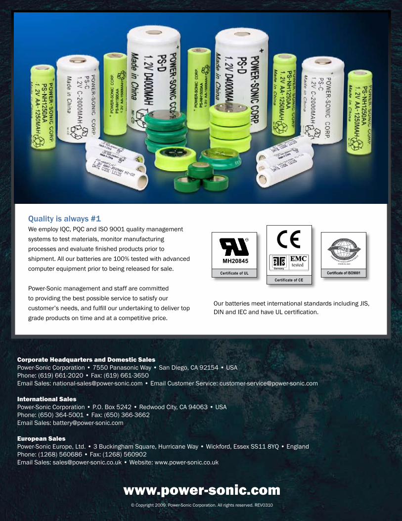
Quality is always #1 We employ IQC, PQC and ISO 9001 quality management systems to test materials, monitor manufacturing processes and evaluate finished products prior to shipment. All our batteries are 100% tested with advanced computer equipment prior to being released for sale.
Power-Sonic management and staff are committed to providing the best possible service to satisfy our customer’s needs, and fulfill our undertaking to deliver top grade products on time and at a competitive price.
Our batteries meet international standards including JIS, DIN and IEC and have UL certification.
Corporate Headquarters and Domestic Sales Power-Sonic Corporation • 7550 Panasonic Way • San Diego, CA 92154 • USAPhone: (619) 661-2020 • Fax: (619) 661-3650Email Sales: [email protected] • Email Customer Service: [email protected]
International Sales Power-Sonic Corporation • P.O. Box 5242 • Redwood City, CA 94063 • USAPhone: (650) 364-5001 • Fax: (650) 366-3662Email Sales: [email protected]
European Sales Power-Sonic Europe, Ltd. • 3 Buckingham Square, Hurricane Way • Wickford, Essex SS11 8YQ • EnglandPhone: (1268) 560686 • Fax: (1268) 560902Email Sales: [email protected] • Website: www.power-sonic.co.uk
www.power-sonic.com© Copyright 2009. Power-Sonic Corporation. All rights reserved. REV0310