Embed Size (px)
Citation preview
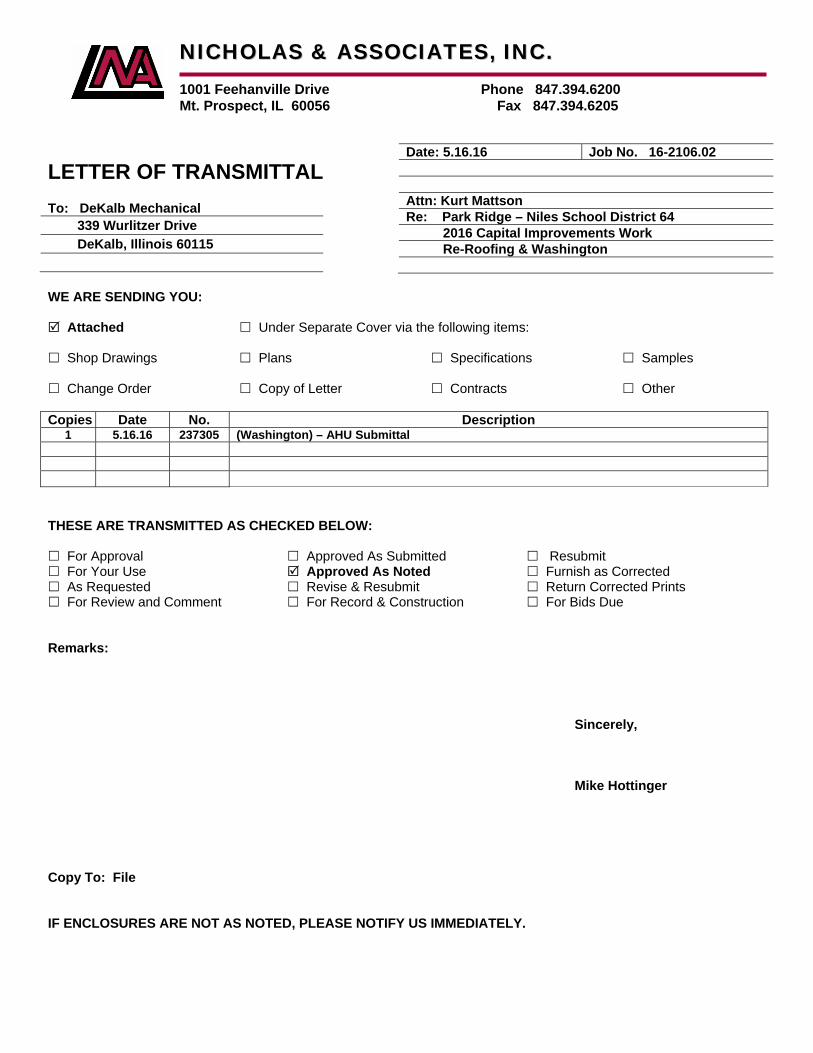
LETTER OF TRANSMITTAL To: DeKalb Mechanical
339 Wurlitzer Drive
DeKalb, Illinois 60115
WE ARE SENDING YOU: Attached Under Separate Cover via the following items: Shop Drawings Plans Specifications Samples Change Order Copy of Letter Contracts Other
Copies Date No. Description 1 5.16.16 237305 (Washington) – AHU Submittal
THESE ARE TRANSMITTED AS CHECKED BELOW: For Approval Approved As Submitted Resubmit For Your Use Approved As Noted Furnish as Corrected As Requested Revise & Resubmit Return Corrected Prints For Review and Comment For Record & Construction For Bids Due
Remarks: Sincerely, Mike Hottinger Copy To: File IF ENCLOSURES ARE NOT AS NOTED, PLEASE NOTIFY US IMMEDIATELY.
NNIICCHHOOLLAASS && AASSSSOOCCIIAATTEESS,, IINNCC..
1001 Feehanville Drive Phone 847.394.6200
Mt. Prospect, IL 60056 Fax 847.394.6205
Date: 5.16.16 Job No. 16-2106.02
Attn: Kurt Mattson
Re: Park Ridge – Niles School District 64
2016 Capital Improvements Work
Re-Roofing & Washington

Mechanica
TO: T
F
1
O
Enclose No. S1 2 Notes: 1. Unit
throuunits
2. Contbrea
3. ContM1.1
4. Prov5. Prov6. Prov7. Furn8. Man
start9. Man
serv
Status AA = ApprAAN = AR&R = RR = Reje _______Signed:
al • Electrical
Teri Wright
FGM Archite
211 West 2
Oak Brook,
d please fin
Section Ite3 73 05 Ai
submitted isugh all neces properly fit tractor respo
akers, devicetractor to ve1.2W. vide 8-row covide 4” base vide drip-pronish one extrufacturer sht-up or 18 mufacturer shice and main
Abbreviationroved
Approved As Revise & Resected
___________Joe W. Nels
Engineers • 83
ects
22nd Street,
IL 60523
nd the follow
em r Handling U
s larger thanssary doorsinside mech
onsible to coes, etc. as rerify coil conn
ooling coil inrails per schof premium ra set of filtehall provide aonths from s
hall provide sntenance of
ns
noted submit
__________son, P.E.eb
37 Oakton Strwww.c
, Suite 705
wing produ
Units (W.AH
n basis of de, passagewahanical roomoordinate anequired to acnection sides
n lieu of 6-rowhedule. efficient mo
ers per unit.a standard pshipment, whstart-up servthe equipme
________
reet, Elk Grovecs2designgrou
L
D
PRO
PROJE
SUBJ
ct submitta
MU-1, 2) T
esign. Contraays, etc. alo
m while maind provide an
ccommodates on units ar
w.
tors.
parts warranthichever occvices and shent. Refer to
e, IL 60007 • Pup.com
LETTER O
DATE: W
JECT: D6
ECT #: 11
JECT: HV
als and/or s
ManufacturTrane
actor to verifng path of in
ntaining requny electrical e submitted re selected p
ty that covercurs first. Reall instruct tho spec sectio
Ph 847.981.188
OF TRAN
ednesday,
64 - 2016 Su
2-P-1 (Was
VAC Subm
hop drawin
rer StatuAAN
fy unit is ablenstallation. Cuired clearanchanges, inunit. per enlarged
rs a period oefer to spec he owner onon 237305, 3
80 • Fax 847.98
NSMITTAL
May 04, 20
ummer Work
shington)
ittals
ngs:
us No1 -
e to be transContractor tonces. ncluding wire
d plan on dra
of one year fsection 2373
n the require3.1.D.
81.1885
L
016
k
otes - 9
sported o verify
e sizes,
awing
from unit 305, 1.8.
ed
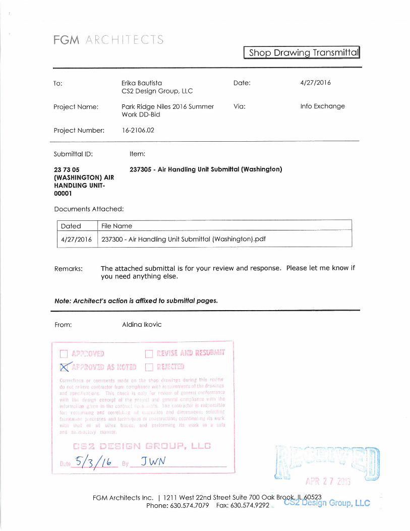

LETTER OF TRANSMITTAL To: FGM Architects
1211 West 22nd Street, Suite 705
Oak Brook, IL 60523
WE ARE SENDING YOU: Attached Under Separate Cover via the following items: Shop Drawings Plans Specifications Samples Change Order Copy of Letter Contracts Other
Copies Date No. Description
1 04.27.16 237300 Air Handling Unit Submittal - Washington
THESE ARE TRANSMITTED AS CHECKED BELOW: For Approval Approved As Submitted Resubmit Copies for Approval For Your Use Approved As Noted Furnish as Corrected As Requested Returned for Corrections Return Corrected Prints For Review and Comment For Record & Construction For Bids Due
Remarks: Sincerely, Lisa Michna Copy To: File IF ENCLOSURES ARE NOT AS NOTED, PLEASE NOTIFY US IMMEDIATELY.
NNIICCHHOOLLAASS && AASSSSOOCCIIAATTEESS,, IINNCC..
1001 Feehanville Drive Phone 847.394.6200
Mt. Prospect, IL 60056 Fax 847.394.6205
Date: April 27, 2016 Job No.
Attn: Teri Wright
RE: Park Ridge Niles CCSD 64
2016 Capital Improvement Work at
Multiple Schools
confirm size of unit

Project Title: Washington School Park Ridge Contractor: DeKalb Mechanical Subcontractor / Supplier: Trane Submittal Date: 04/22/2016 Specification Number: 237300 - AHU Submittal Notes: N/A
DeKalb Mechanical
Sheet Metal ~ HVAC ~ Refrigeration
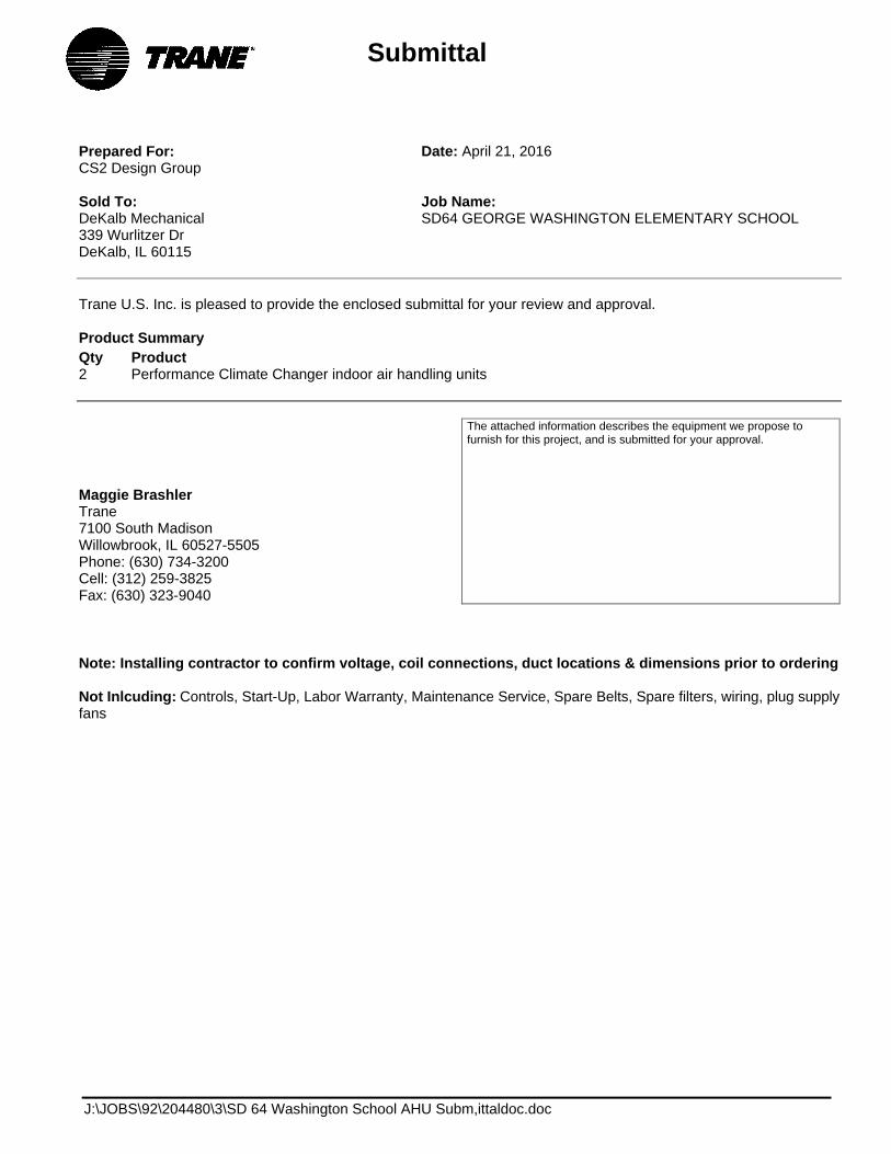
Prepared For: CS2 Design Group
Date: April 21, 2016
Sold To: DeKalb Mechanical 339 Wurlitzer Dr DeKalb, IL 60115
Job Name: SD64 GEORGE WASHINGTON ELEMENTARY SCHOOL
Trane U.S. Inc. is pleased to provide the enclosed submittal for your review and approval.
Product Summary Qty Product 2 Performance Climate Changer indoor air handling units
Maggie Brashler Trane 7100 South Madison Willowbrook, IL 60527-5505 Phone: (630) 734-3200 Cell: (312) 259-3825 Fax: (630) 323-9040
The attached information describes the equipment we propose to furnish for this project, and is submitted for your approval.
Note: Installing contractor to confirm voltage, coil connections, duct locations & dimensions prior to ordering
Not Inlcuding: Controls, Start-Up, Labor Warranty, Maintenance Service, Spare Belts, Spare filters, wiring, plug supply fans
Submittal
J:\JOBS\92\204480\3\SD 64 Washington School AHU Subm,ittaldoc.doc
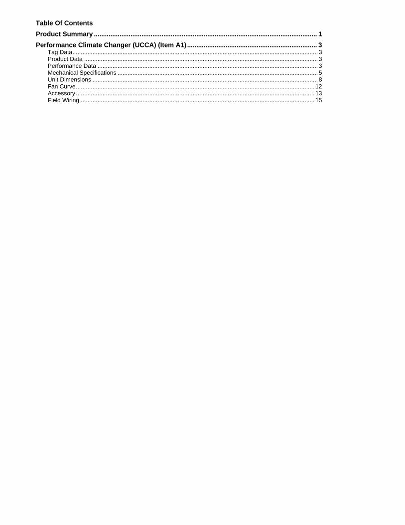
Table Of Contents
Product Summary .......................................................................................................................... 1
Performance Climate Changer (UCCA) (Item A1) ....................................................................... 3 Tag Data ................................................................................................................................................... 3 Product Data ............................................................................................................................................ 3 Performance Data .................................................................................................................................... 3 Mechanical Specifications ........................................................................................................................ 5 Unit Dimensions ....................................................................................................................................... 8 Fan Curve ............................................................................................................................................... 12 Accessory ............................................................................................................................................... 13 Field Wiring ............................................................................................................................................ 15

SD64 GEORGE WASHINGTON ELEMENTARY SCHOOL April 22, 2016
FLD = Furnished by Trane U.S. Inc. / Installed by Others
Equipment Submittal Page 3 of 18
Tag Data - Performance Climate Changer (UCCA) (Qty: 2) Item Tag(s) Qty
Description Model Number
A1 W.AHU-1, W-AHU-2
2 Performance Climate Changer UCCA
Product Data - Performance Climate Changer (UCCA) Item: A1 Qty: 2 Tag(s): W.AHU-1, W-AHU-2
Performance Climate Changer (UCCA) Vertical housed fan with top back discharge Unit Size 12 Square Feet of Coil 208/60/3 Indoor unit Polymer Drain pan, RH Coil & Drain Conn. / RH Motor & Drive Location 2 row preheat hydronic coil with 9 fins per inch 6 row hydronic cooling coil with 9 fins per inch Aluminum fins, galvanized coil casing, 1/2" coils Terminal block plus starter or disconnect 7- 1/2 horsepower motor Housed fan w/VFD and Shaft Grounding Ring 2" flat filter rack 2" MERV 8 Standard - door on motor side
Performance Data - Performance Climate Changer (UCCA)
Tags W.AHU-1, W-AHU-2
Design airflow (cfm) 5750 Total cooling capacity (MBh) 229.29 Sensible capacity (MBh) 175.16 Main coil system type Hydronic Fluid type Water Fluid volume (gal) 8.00 Preheat fluid volume (gal) 3.33 Cooling EDB (F) 82.00 Cooling EWB (F) 66.90 Cooling LDB (F) 54.34 Cooling LWB (F) 53.89 Cooling ent fluid temp (F) 44.00 Cooling lvg fluid temp (F) 55.42 Cooling fluid temp rise (F) 11.42 Cooling flow rate (gpm) 40.00 Cooling fluid PD (ft H2O) 5.48 Cooling face velocity (ft/min) 468 Fluid freeze pt (F) 32.00 Preheat coil system type Hydronic Preheat fluid type Water Total preheat capacity (MBh) 352.63 Preheat EAT (F) 45.20 Preheat LAT (F) 101.75 Preheat ent fluid temp (F) 180.00 Preheat lvg fluid temp (F) 144.76 Preheat fluid temp drop (F) 35.24 Preheat flow rate (gpm) 20.00 Preheat fluid PD (ft H2O) 0.74 Preheat coil face velocity (ft/min) 468 Preheat fluid freeze pt (F) 32.00 Reheat coil type None Basis of selection Cooling Two pipe changeover No

SD64 GEORGE WASHINGTON ELEMENTARY SCHOOL April 22, 2016
FLD = Furnished by Trane U.S. Inc. / Installed by Others
Equipment Submittal Page 4 of 18
Tags W.AHU-1,
W-AHU-2 Elevation (ft) 0.00 Supply fan ESP (in H2O) 2.000 Supply fan TSP (in H2O) 3.378 Supply fan quantity (Each) 1.00 Supply total brake hp per fan (hp) 5.274 Supply fan speed (rpm) 1076 Cooling APD (in H2O) 0.627 Preheat APD (in H2O) 0.158 Filter/Mixing section APD (in H2O)
0.593
Discharge velocity (ft/min) 2261 Unit full load amps (A) 28.50 Unit max fuse size (A) 60.00 Unit min circuit ampacity (A) 35.50 Supply VFD panel amps (A) 28.00 Run acoustics? No Unit length (in) 50.068 Unit width (in) 71.000 Unit height (in) 80.060 Installed weight (lb) 1033.1 Rigging weight (lb) 938.9 Cooling fluid velocity (ft/s) 2.98 Preheat fluid velocity (ft/s) 1.49

SD64 GEORGE WASHINGTON ELEMENTARY SCHOOL April 22, 2016
FLD = Furnished by Trane U.S. Inc. / Installed by Others
Equipment Submittal Page 5 of 18
Mechanical Specifications - Performance Climate Changer (UCCA) Item: A1 Qty: 2 Tag(s): W.AHU-1, W-AHU-2
GENERAL
Lifting Instructions Performance Climate Changer air handlers must be rigged, lifted, and installed in strict accordance with the Installation, Operation, and Maintenance manual (CLCH-SVX009A-EN) for UCCA air handlers. The units are also to be installed in strict accordance with the specifications.
Per ASHRAE 62.1 recommendation, indoor air handling units will be shipped stretch-wrapped to protect unit from in-transit rain and debris.
Installing contractor is responsible for long term storage in accordance with the Installation, Operation, and Maintenance manual (CLCH-SVX009A-EN).
Unit shall be UL and C-UL Listed.
Where applicable air-handling performance data shall be certified in accordance with AHRI Standard 430. For units with housed fans or single direct drive plenum fans, fans shall be certified as complying with AHRI Standard 430. Air handling units with multiple direct drive plenum fans, or direct drive plenum fans incorporated with ECM style motors are outside the scope of AHRI 430. These fans however are rated in accordance with AHRI 430.
Coil performance shall be certified in accordance with AHRI Standard 410.
Unit Construction
Casing Construction All unit panels shall be 2-inch solid, double-wall construction to facilitate cleaning of unit interior. All exterior and interior AHU panels will be made of galvanized steel. Motor and drive locations can be on the same side as the unit coil connections or on the opposite side. The casing shall be able to withstand up to 4" w.g. positive or negative static pressure. The unit panels shall not exceed .005 inch deflection per inch of panel span at 4" w.g. positive or negative static pressure.
Floor Construction The unit floor shall be of sufficient strength to support a 300.0 lb load during maintenance activities and shall deflect no more than .005 inch per inch of panel span when sitting on a support structure.
Insulation Panel insulation shall provide a minimum thermal resistance (R) value of 13 ft²*h*ºF/Btu throughout the entire unit. Insulation shall completely fill the panel cavities in all directions so that no voids exist and settling of insulation is prevented. Panel insulation shall comply with NFPA 90A.
Drain Pan All units shall be provided with an insulated assembly of polymer material or stainless steel. To address indoor air quality (IAQ), the drain pan shall be designed in accordance with ASHRAE 62.1 being of sufficient size to collect all condensation produced from the coil and sloped in two planes promoting positive drainage to eliminate stagnant water conditions. The outlet shall be located at the lowest point of the pan and shall be sufficient diameter to preclude drain pan overflow under any normally expected operating condition. All drain pan connections shall be visible external to the unit.
Access Door Construction Access doors shall be 2-inch double-wall construction. Interior and exterior door panels shall be of the same construction as the interior and exterior wall panels, respectively. Surface-mounted handles shall be provided to allow quick access to the interior of the unit. Handle hardware shall be designed to prevent unintended closure. Access doors shall be hinged and removable for quick, easy access. Door handle hardware shall be adjustable and visually indicate locking position of door latch external to the section.
Filters
2-inch pleated media filters made with 100% synthetic fibers that are continuously laminated to a supported steel-wire grid with water repellent adhesive shall be provided. Filters shall be capable of operating up to 625 fpm face velocity without loss of filter efficiency and holding capacity. The filters shall have a MERV 8 rating when tested in accordance

SD64 GEORGE WASHINGTON ELEMENTARY SCHOOL April 22, 2016
FLD = Furnished by Trane U.S. Inc. / Installed by Others
Equipment Submittal Page 6 of 18
with the ANSI/ASHRAE Standard 52.2.
COIL SECTION The coil section shall be provided complete with coil and coil holding frame. The coils shall be installed such that headers and return bends are enclosed by unit casings. The drainpan outlet shall be located at the lowest point of the pan and shall be sufficient diameter to preclude drain pan overflow under any normally expected operating condition.
No casing penetrations supplied for hydronic drain and vents. If required, piping contractor will need to drill drain and vent penetrations using factory located features provided in coil panel.
Water Coils Hydronic coils have ½"OD x 0.016" W round seamless copper tubes mechanically bonded to coil fins. Coil fins are aluminum with full fin collars that provide maximum fin-tube contact and accurate spacing. Coils are available with 9, 12, and 14 fins per inch. Manufacturer shall not allow selections where moisture carryover could occur at design conditions. For hydronic coils used in a two-pipe system, the unit manufacturer shall provide performance data in both the cooling and heating mode.
Hydronic coils used as heating only will be available in one or two-row configurations. Hydronic coils used as cooling only will be available in four, six, or eight-row configurations. Multi-row hydronic coils have continuous tube circuits arranged for counterflow (water flow counter to the direction of unit airflow). The coil casing may be galvanized or stainless steel. Coils have round seamless copper pipe headers with NPT external thread steel pipe connections. Coils have one vent and one drain connection consisting of 3/8" NPT internal thread copper adapter with steel square head pipe plug. Supply and return connections are located outside the unit casing (on the same side of the unit) and are clearly labeled to facilitate field piping. Coils are proof-tested to 450 psig and leak-tested under water to 300 psig. Maximum standard operating conditions are 300 psig and 200F. Coil performance data and coils containing water or ethylene glycol shall be certified in accordance with AHRI Standard 410. Propylene glycol and calcium chloride, or mixtures thereof, are outside the scope of AHRI Standard 410 and, therefore, do not require AHRI 410 rating or certification.
Tubes are 1/2" [13mm] OD 0.016" [0.406mm] thick copper.
FC FAN SECTION The fan shall be a double-width, double-inlet, multi-blade-type, forward-curved (FC) fan. The fan shall be equipped with permanently lubricated, anti-friction bearings with an L-50 life of 200,000 hours as calculated per ANSI/AFBMA Standard 9. All fan wheels are dynamically balanced by the fan vendor or unit manufacturer.
Fans selected with a shaft grounding ring shall have a maintenance free, circumferential conductive micro fiber ring installed on the fan motor to discharge shaft currents to ground.
The drives shall be constant speed with fixed-pitch sheaves. The drives shall be selected at a minimum 50 percent larger than the motor brake horsepower (1.5 service factor).

SD64 GEORGE WASHINGTON ELEMENTARY SCHOOL April 22, 2016
FLD = Furnished by Trane U.S. Inc. / Installed by Others
Equipment Submittal Page 7 of 18
Motor Frame The motor shall be mounted integral to the isolated fan assembly and furnished by the unit manufacturer. The motor is mounted inside the unit casing on an adjustable base to permit adjustment of drive belt tension (not applicable for direct drive plenum fans). The motor shall meet or exceed all NEMA Standards Publication MG 1 requirements and comply with NEMA Premium efficiency levels when applicable except for fractional horsepower motors which are not covered by the NEMA classification. The motor shall be T-frame, squirrel cage with size, type, and electrical characteristics as shown on the equipment schedule. Refer to the Product Data section for selected fan motors within each unit.
Fan Isolation All fans, including direct drive plenum fans, shall be internally isolated to inhibit noise and vibration through the ductwork and building structure. A flexible connection shall be installed between fan and unit casing to ensure complete isolation. If fans and motors are not internally isolated, then the entire unit shall be externally isolated from the building, including supply and return duct work, piping, and electrical connections. External isolation shall be furnished by the installing contractor in order to avoid transmission of noise and vibration through the ductwork and building structure.
VFD A Variable Frequency Drive (VFD) shall be provided when variable air volume control is required for fan operation. Whether for single fan, or dual fan applications, a single VFD shall be provide to ensure proper operation and to optimize operating life. Each VFD shall be properly sized, factory mounted, wired to the fan motor, and commissioned to facilitate temporary heating, cooling, ventilation, and/or timely completion of the project. The VFD package shall also include:
a) Electronic manual speed control b)Inlet fuses to provide maximum protection against inlet short circuit c) Current limited stall prevention d) Auto restart after momentary power loss e) Speed search for starting into rotating motor f) Anti-windmill w/DC injection before start g) Phase-to-phase short circuit protection h) Ground fault protection
Units with factory-mounted controls shall include power wiring from the VFD panel to the control system, binary output on/off wiring, analog output-speed-signal wiring, binary fault signal wiring and all interfacing wiring between the VFD and the direct control interface.
The VFD shall be covered by UL1995 Standards.
Control Interface A control interface is available that includes: · Fan motor disconnect switch · Fused transformer(s) · Customer terminal strip for field-provided controls · For a control interface without a VFD, it will also include a starter with a motor overload and a motor contactor. · For a control interface with a VFD, it will not include a starter..
Also, various end device options are available with the control interface wired to a terminal strip. Binary end device options include: · Low limit protection · Condensate overflow switch · Fan status switch · Filter status switch
Analog end device options are: · Discharge air sensor · Mixed air sensor · Return air sensor · Damper actuator

SD64 GEORGE WASHINGTON ELEMENTARY SCHOOL April 22, 2016
FLD = Furnished by Trane U.S. Inc. / Installed by Others
Equipment Submittal Page 8 of 18
Unit Dimensions - Performance Climate Changer (UCCA) Item: A1 Qty: 2 Tag(s): W.AHU-1, W-AHU-2
CO
IL 2C
OIL 1
38 5
/8"
36 5
/8"67
"
65"
4"
80 1
/8"
71"
36 1
/16" 40
1/8
"
16 1
3/16
"
23"
10"
11 5
/8"
23 5
/8"
6 13
/16"
12 3
/4"
7 1/
8"
2 15
/16"
14 1
/16"
19 3
/16"
25
7/8
"
19 3
/16"
1" N
.P.T
.E.
12
1 3/
16"
32"
Doo
rs32
" W
idth
x 3
8" H
eigh
t
E
xter
nal V
FD
Ext
erna
l uni
t con
trol
ler
Hou
sed
fan
- 18
" di
amet
erS
uppl
y fa
n 7.
500
hp 2
08.0
V
1 2 3
4
5 6 7
1
2
3
4
7
56
TP
BK
dis
char
ge o
peni
ng19
3/1
6" x
19
3/16
"
C
oolin
g co
il -
6 ro
wH
eatin
g co
il -
2 ro
wF
lat f
ilter
- 2
" M
ER
V 8
16 in
. x 2
0 in
. ( 2
)16
in. x
25
in. (
1 )
20 in
. x 2
0 in
. ( 2
)20
in. x
25
in. (
1 )
OP
EN
ING
AN
D D
IME
NS
ION
S M
AY
VA
RY
FR
OM
CO
NT
RA
CT
DO
CU
ME
NT
S /
RE
TU
RN
OF
AP
PR
OV
ED
DR
AW
ING
S C
ON
ST
ITU
TE
S A
CC
EP
TA
NC
E O
F T
HE
SE
VA
RIA
NC
ES
/ N
OT
TO
SC
ALE
Act
ual a
irflo
w:
Uni
t siz
e:
Pro
duct
gro
up: I
ndoo
r U
nit
Uni
t Cas
ing:
2in
Dou
ble
Wal
l
Rig
ging
Wei
ght:
Inst
alle
d W
eigh
t:P
erfo
rman
ce C
limat
e C
hang
er
Air
Han
dler
s
5750
cfm
1033
.1 lb
938.
9 lb
EQ
UIP
ME
NT
LIS
T

SD64 GEORGE WASHINGTON ELEMENTARY SCHOOL April 22, 2016
FLD = Furnished by Trane U.S. Inc. / Installed by Others
Equipment Submittal Page 9 of 18
Unit Dimensions - Performance Climate Changer (UCCA) Item: A1 Qty: 2 Tag(s): W.AHU-1, W-AHU-2
1COIL
2COIL
12
19.0 lb
120.0 lb
22.0 lb
518.0 lb
50 1/16"
OPENING AND DIMENSIONS MAY VARY FROM CONTRACT DOCUMENTS / RETURN OF APPROVED DRAWINGS CONSTITUTES ACCEPTANCE OF THESE VARIANCES / NOT TO SCALE
Actual airflow:
Unit size:
Product group: Indoor Unit
Unit Casing: 2in Double Wall
Rigging Weight:
Installed Weight: Performance Climate Changer
Air Handlers
1033.1 lb
938.9 lb5750 cfm
Main Unit
Coil 1 installed weight
Coil 2 installed weight
VFD
Electric Heater
Motor
Component
Filter / Mixbox weight
Overall Elevation View: Right - Shipping splits indicated by bold outline.
Access section with coil
108.5 lb
245.7 lb

SD64 GEORGE WASHINGTON ELEMENTARY SCHOOL April 22, 2016
FLD = Furnished by Trane U.S. Inc. / Installed by Others
Equipment Submittal Page 10 of 18
Unit Dimensions - Performance Climate Changer (UCCA) Item: A1 Qty: 2 Tag(s): W.AHU-1, W-AHU-2
6 3/
8" (
162
mm
)
(10
mm
)3/
8" (
NP
TI)
Dra
in
(51
mm
)2"
(N
PT
E)
Ret
urn
(51
mm
)2"
(N
PT
E)
Sup
ply
(10
mm
)3/
8" (
NP
TI)
Ven
t
4 3/
4" (
121
mm
)2
1/2"
(64
mm
)
(568
mm
)22
3/8
"
(489
mm
)19
1/4
"
(10
mm
)3/
8" (
NP
TI)
Dra
in
(51
mm
)2"
(N
PT
E)
Ret
urn
(51
mm
)2"
(N
PT
E)
Sup
ply
(10
mm
)3/
8" (
NP
TI)
Ven
t
(568
mm
)22
3/8
"
(489
mm
)19
1/4
"
1 3/
4" (
44 m
m)
7 1/
4" (
184
mm
)
12
Coi
l con
nect
ion
view
: Rig
ht
NP
TE
: Nat
iona
l Pip
e T
hrea
d E
xter
nal C
onne
ctio
nO
PE
NIN
G A
ND
DIM
EN
SIO
NS
MA
Y V
AR
Y F
RO
M C
ON
TR
AC
T D
OC
UM
EN
TS
/ R
ET
UR
N O
F A
PP
RO
VE
D D
RA
WIN
GS
CO
NS
TIT
UT
ES
AC
CE
PT
AN
CE
OF
TH
ES
E V
AR
IAN
CE
S /
NO
T T
O S
CA
LE
Act
ual a
irflo
w:
Uni
t siz
e:
Pro
duct
gro
up: I
ndoo
r U
nit
Rig
ging
Wei
ght:
Inst
alle
d W
eigh
t:P
erfo
rman
ce C
limat
e C
hang
er
Air
Han
dler
s
NP
TI:
Nat
iona
l Pip
e T
hrea
d In
tern
al C
onne
ctio
n
Not
e: N
ot a
ll co
mpo
nent
s or
acc
esso
ries
show
n. M
ain
unit
show
n fo
r re
fere
nce.
5750
cfm
1033
.1 lb
938.
9 lb
Uni
t Cas
ing:
2in
Dou
ble
Wal
l Foa
m

SD64 GEORGE WASHINGTON ELEMENTARY SCHOOL April 22, 2016
FLD = Furnished by Trane U.S. Inc. / Installed by Others
Equipment Submittal Page 11 of 18
Unit Dimensions - Performance Climate Changer (UCCA) Item: A1 Qty: 2 Tag(s): W.AHU-1, W-AHU-2
Note(s): At a minimum, the above clearance dimensions are recommended on one side of the unit for regular service and maintenance. Refer to as-built submittal for locations of items such as filter access doors, coil, piping connections, motor locations, etc. Sufficient clearance must be provided on all sides of unit for removal of access panels, plug panels, or section-to-section attachment brackets Clearance for starters, VFD's, or other high-voltage devices must be provided per NEC requirements.
UCCA Service Clearances
UNIT SIZE
Component
3 6 8 10 12 14 17 21 25 30
Filter A 40.0
44.0
42.0
42.0
40.0
45.0
45.0
45.0
51.0
51.0
Coil Pull B 49.0
62.0
66.0
78.0
86.0
86.0
94.0
94.0
96.0
109.0
Fan Access, horizontal unit (motor side) C 48.0
48.0
48.0
51.0
54.0
58.0
61.0
61.0
66.0
66.0
Fan access, horizontal unit (opposite motor side) C 15.0
18.0
15.0
15.0
17.0
18.0
22.0
23.0
24.0
24.0 Fan Access, vertical unit (motor side) C 48.0
48.0
48.0
51.0
54.0
58.0
61.0
61.0
Fan access, vertical unit (opposite motor side) C 25.0
28.0
21.0
23.0
27.0
27.0
31.0
31.0
Control Box D 56.0
56.0
56.0
56.0
56.0
56.0
56.0
56.0
56.0
56.0 VFD E 48.0
48.0
48.0
48.0
48.0
48.0
48.0
48.0
48.0
48.0 EH F 48.0
48.0
48.0
48.0
48.0
48.0
48.0
48.0
48.0
48.0 Access Door - Access Section G 15.0
15.0
15.0
15.0
15.0
15.0
15.0
15.0
15.0
15.0
SD64 GEORGE WASHINGTON ELEMENTARY SCHOOL April 22, 2016
FLD = Furnished by Trane U.S. Inc. / Installed by Others
Equipment Submittal Page 12 of 18
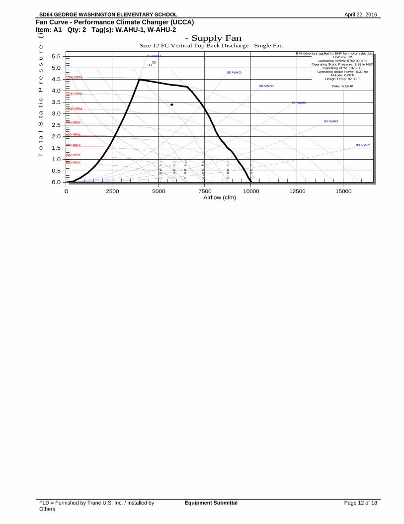
Fan Curve - Performance Climate Changer (UCCA) Item: A1 Qty: 2 Tag(s): W.AHU-1, W-AHU-2
1.
00
h
p
1.
50
h
p
2.0
0
hp
3.
00
h
p
5.
00
h
p
7.5
0
hp500 RPM
600 RPM
700 RPM
800 RPM
900 RPM
1000 RPM
1100 RPM
1200 RPM
25 %WO
50 %WO
60 %WO
70 %WO
80 %WO
90 %WO
5 % drive loss applied to BHP for motor selection.
UnitSize: 12Operating Airflow: 5750.00 cfm
Operating Static Pressure: 3.38 in H2OOperating RPM: 1076.00
Operating Brake Power: 5.27 hpAltitude: 0.00 ft
Design Temp: 82.00 F
Date: 4/22/16
32
33
0.0
0.5
1.0
1.5
2.0
2.5
3.0
3.5
4.0
4.5
5.0
5.5
0 2500 5000 7500 10000 12500 15000
- Supply FanSize 12 FC Vertical Top Back Discharge - Single Fan
To
tal
Sta
tic
Pr
es
su
re
(
in
H2
O)
Airflow (cfm)
SD64 GEORGE WASHINGTON ELEMENTARY SCHOOL April 22, 2016
FLD = Furnished by Trane U.S. Inc. / Installed by Others
Equipment Submittal Page 13 of 18
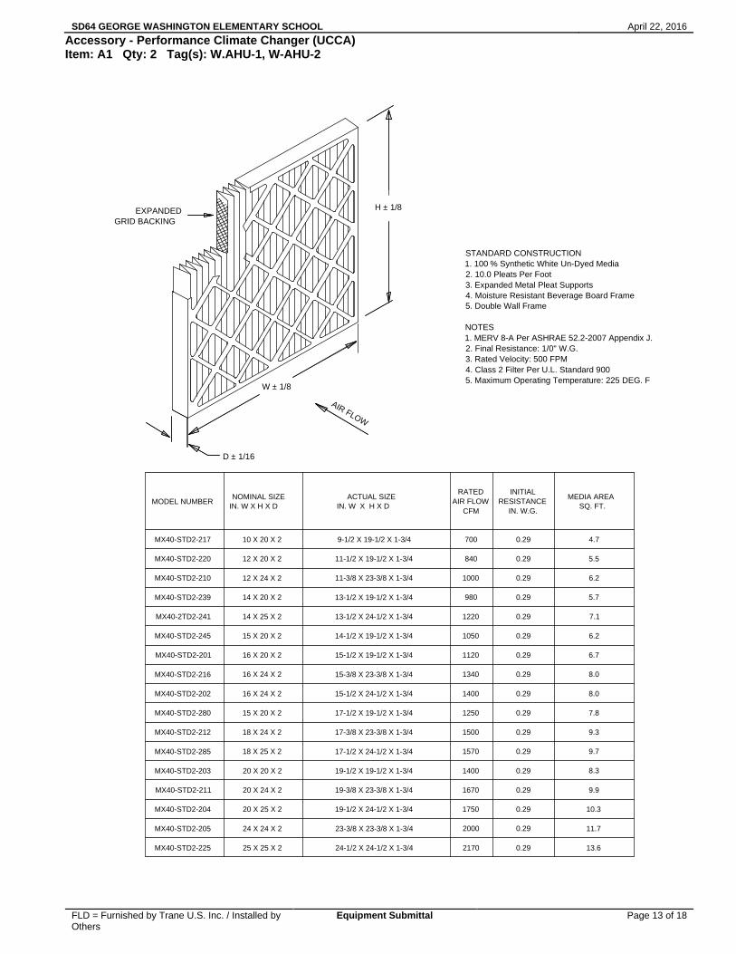
Accessory - Performance Climate Changer (UCCA) Item: A1 Qty: 2 Tag(s): W.AHU-1, W-AHU-2
MODEL NUMBERNOMINAL SIZE
IN. W X H X DACTUAL SIZE
IN. W X H X D
RATEDAIR FLOW
CFM
INITIALRESISTANCE
IN. W.G.
MEDIA AREASQ. FT.
MX40-STD2-217 10 X 20 X 2 9-1/2 X 19-1/2 X 1-3/4 700 0.29 4.7
MX40-STD2-220 12 X 20 X 2 11-1/2 X 19-1/2 X 1-3/4 840 0.29 5.5
MX40-STD2-210 12 X 24 X 2 11-3/8 X 23-3/8 X 1-3/4 1000 0.29 6.2
MX40-STD2-239 14 X 20 X 2 13-1/2 X 19-1/2 X 1-3/4 980 0.29 5.7
MX40-2TD2-241 14 X 25 X 2 13-1/2 X 24-1/2 X 1-3/4 1220 0.29 7.1
MX40-STD2-245 15 X 20 X 2 14-1/2 X 19-1/2 X 1-3/4 1050 0.29 6.2
MX40-STD2-201 16 X 20 X 2 15-1/2 X 19-1/2 X 1-3/4 1120 0.29 6.7
MX40-STD2-216 16 X 24 X 2 15-3/8 X 23-3/8 X 1-3/4 1340 0.29 8.0
MX40-STD2-202 16 X 24 X 2 15-1/2 X 24-1/2 X 1-3/4 1400 0.29 8.0
MX40-STD2-280 15 X 20 X 2 17-1/2 X 19-1/2 X 1-3/4 1250 0.29 7.8
MX40-STD2-212 18 X 24 X 2 17-3/8 X 23-3/8 X 1-3/4 1500 0.29 9.3
MX40-STD2-285 18 X 25 X 2 17-1/2 X 24-1/2 X 1-3/4 1570 0.29 9.7
MX40-STD2-203 20 X 20 X 2 19-1/2 X 19-1/2 X 1-3/4 1400 0.29 8.3
MX40-STD2-211 20 X 24 X 2 19-3/8 X 23-3/8 X 1-3/4 1670 0.29 9.9
MX40-STD2-204 20 X 25 X 2 19-1/2 X 24-1/2 X 1-3/4 1750 0.29 10.3
MX40-STD2-205 24 X 24 X 2 23-3/8 X 23-3/8 X 1-3/4 2000 0.29 11.7
MX40-STD2-225 25 X 25 X 2 24-1/2 X 24-1/2 X 1-3/4 2170 0.29 13.6
EXPANDEDGRID BACKING
D ± 1/16
W ± 1/8
AIR FLOW
H ± 1/8
STANDARD CONSTRUCTION1. 100 % Synthetic White Un-Dyed Media2. 10.0 Pleats Per Foot3. Expanded Metal Pleat Supports4. Moisture Resistant Beverage Board Frame5. Double Wall Frame
NOTES1. MERV 8-A Per ASHRAE 52.2-2007 Appendix J.2. Final Resistance: 1/0" W.G.3. Rated Velocity: 500 FPM4. Class 2 Filter Per U.L. Standard 9005. Maximum Operating Temperature: 225 DEG. F

SD64 GEORGE WASHINGTON ELEMENTARY SCHOOL April 22, 2016
FLD = Furnished by Trane U.S. Inc. / Installed by Others
Equipment Submittal Page 14 of 18
Accessory - Performance Climate Changer (UCCA) Filter Schedule Item: A1 Qty: 2 Tag(s): W.AHU-1, W-AHU-2
Unit Tag(s)
Unit Size
Filter Arrangement
Filter Type \ MERV Rating
Filter Quantity
Filter Size
W.AHU-1, W-AHU-2
Unit Size 12 Square Feet of Coil
2" flat filter rack 2" MERV 8
2 1 2 1
16 in. x 20 in. 16 in. x 25 in. 20 in. x 20 in. 20 in. x 25 in.

SD64 GEORGE WASHINGTON ELEMENTARY SCHOOL April 22, 2016
FLD = Furnished by Trane U.S. Inc. / Installed by Others
Equipment Submittal Page 15 of 18
Field Wiring - Performance Climate Changer (UCCA) Item: A1 Qty: 2 Tag(s): W.AHU-1, W-AHU-2
1Q1
L3
L2
L1
6A5A
4A
GO
TO
CO
NT
RO
L S
CH
EM
AT
IC
GO
TO
CO
NT
RO
L S
CH
EM
AT
IC
GO
TO
CO
NT
RO
L S
CH
EM
AT
IC
GO
TO
CO
NT
RO
L S
CH
EM
AT
IC
GO
TO
CO
NT
RO
L S
CH
EM
AT
IC
GO
TO
CO
NT
RO
L S
CH
EM
AT
IC
GO
TO
CO
NT
RO
L S
CH
EM
AT
IC
GO
TO
CO
NT
RO
L S
CH
EM
AT
IC
GO
TO
CO
NT
RO
L S
CH
EM
AT
ICG
O T
O C
ON
TR
OL
SC
HE
MA
TIC
20V
FD
9T1
24V
FD
FU
SE
9F3
22V
FD
FU
SE
9F2
20V
FD
FU
SE
9F1
43M
OT
OR
12M
120
PO
WE
R D
IST
RIB
UT
ION
BLO
CK
1X1
31C
ON
TR
OL
TR
AN
SF
OR
ME
R1T
115
UN
IT D
ISC
ON
NE
CT
SW
ITC
H1Q
1Z
ON
ED
ES
CR
IPT
ION
DE
VIC
E
BLU
YE
L
OR
G23
0VB
LK
460V
BLK
RE
D57
5V
1T1
24V
INS
ET
B
BLK
/RE
D
400A
9T1
GN
D
CO
MM
5+ 6
8
CO
MM
5- 6
9
FA
ULT
+ 0
4
FA
ULT
- 0
5
L3 L2 L1 18 R
UN
12 +
24V
DC
53 R
EF
IN
55 C
OM
W/9
8V
/97
U/9
6
5
401B
402B
407B
408B
404B
403B
409B
410B
9F1
9F2
9F3
8A 9A7A
1X1
6A 5A 4A4C5C6C
BLK
BLK
R
ED
RE
D
208V
6B 5B 4B
5
BLU
YE
L
1T1
24V
BLU
YE
L
1T1
24V
BLU
YE
L
1T1
24V
BLK
401B
402B
2M1
M 318
B
12B
15B
SP
LIC
E
12A
12A
15A
15A
18A
18A
SP
LIC
E
SP
LIC
E
6
PO
WE
R S
CH
EM
AT
IC P
AG
E 1
OF
2
FA
ILU
RE
TO
DO
SO
MA
Y C
AU
SE
DA
MA
GE
TO
TH
E
UN
IT T
ER
MIN
ALS
AR
E N
OT
DE
SIG
NE
D T
O A
CC
EP
T
N'U
TIL
ISE
R Q
UE
DE
S C
ON
DU
CT
EU
RS
EN
CU
IVR
E!
LES
BO
RN
ES
DE
L'U
NIT
E N
E S
ON
T P
AS
CO
NC
UE
SP
OU
R R
EC
EV
OIR
D'A
UT
RE
S T
YP
ES
DE
CO
ND
UC
TE
UR
S.
L'U
TIL
ISA
TIO
N D
E T
OU
T A
UT
RE
CO
ND
UC
TE
UR
PE
UT
SI N
O L
O H
AC
E, P
UE
DE
OC
AS
ION
AR
DA
NO
AL
EQ
UIP
O.
PA
RA
AC
EP
TA
R O
TR
OS
TIP
OS
DE
CO
ND
UC
TO
RE
S.
LAS
TE
RM
INA
LES
DE
LA
UN
IDA
D N
O E
ST
AN
DIS
EN
AD
AS
iUT
ILIC
E U
NIC
AM
EN
TE
CO
ND
UC
TO
RE
S D
E C
OB
RE
!
EN
DO
MM
AG
ER
L'E
QU
IPE
ME
NT
.
PR
EC
AU
CIO
N
OT
HE
R T
YP
ES
OF
CO
ND
UC
TO
RS
.
EQ
UIP
ME
NT
.
AT
TE
NT
ION
US
E C
OP
PE
R C
ON
DU
CT
OR
S O
NLY
!
CA
UT
ION
INC
LUD
ING
RE
MO
TE
DIS
CO
NN
EC
TS
AN
D
AV
ER
TIS
SE
ME
NT
AD
VE
RT
EN
CIA
NE
PA
S R
ES
PE
CT
ER
CE
S M
ES
UR
ES
DE
FO
LLO
W L
OC
K O
UT
AN
D T
AG
PR
OC
ED
UR
ES
BE
FO
RE
SE
RV
ICIN
G. I
NS
UR
E T
HA
T A
LLM
OT
OR
CA
PA
CIT
OR
S H
AV
E D
ISC
HA
RG
ED
ST
OR
ED
VO
LTA
GE
. U
NIT
S W
ITH
VA
RIA
BLE
INS
TR
UC
TIO
NS
FO
R C
AP
AC
ITO
R D
ISC
HA
RG
E.
SE
RV
ICIN
G C
OU
LD R
ES
ULT
IN
DE
AT
H O
R
INS
TR
UC
TIO
NS
DE
L'E
NT
RA
INE
ME
NT
PO
UR
VIT
ES
SE
VA
RIA
BLE
, SE
RE
PO
RT
ER
AU
X
DE
CH
AR
GE
S.
DA
NS
LE
CA
S D
'UN
ITE
SLE
S C
ON
DE
NS
AT
EU
RS
DE
S M
OT
EU
RS
SO
NT
TO
UT
E IN
TE
RV
EN
TIO
N.
VE
RIF
IER
QU
E T
OU
SV
ER
RO
UIL
LAG
E E
T D
ES
ET
IQU
ET
TE
S A
VA
NT
OU
VR
IR L
ES
SE
CT
ION
NE
UR
S A
DIS
TA
NC
E,
PR
EC
AU
TIO
N P
EU
T E
NT
RA
INE
R D
ES
BLE
SS
UR
ES
GR
AV
ES
PO
UV
AN
T E
TR
E
DE
CH
AR
GE
R L
ES
CO
ND
EN
SA
TE
UR
S.
MO
RT
ELL
ES
.
TE
NS
ION
DA
NG
ER
EU
SE
!
SP
EE
D D
RIV
E, R
EF
ER
TO
DR
IVE
FA
ILU
RE
TO
DO
TH
E A
BO
VE
BE
FO
RE
CO
MP
OR
TA
NT
DE
S E
NT
RA
INE
ME
NT
S A
PU
IS S
UIV
RE
LE
S P
RO
CE
DU
RE
S D
E
CO
UP
ER
TO
UT
ES
LE
S T
EN
SIO
NS
ET
SE
RIO
US
INJU
RY
.WA
RN
ING
DIS
CO
NN
EC
T A
LL E
LEC
TR
IC P
OW
ER
HA
ZA
RD
OU
S V
OLT
AG
E!
CO
NS
ULT
E L
AS
INS
TR
UC
CIO
NE
S P
AR
A L
AD
IRE
CC
ION
DE
VE
LOC
IDA
D V
AR
IAB
LE,
PA
RA
LA
S U
NID
AD
ES
CO
N E
JE D
E
SE
RV
ICIO
. A
SE
GU
RE
SE
DE
QU
E T
OD
OS
ET
IQU
ET
AD
O A
NT
ES
DE
PR
OC
ED
ER
AL
SIG
A L
OS
PR
OC
ED
IMIE
NT
OS
DE
CIE
RR
E Y
INC
LUS
O L
AS
DE
SC
ON
EX
ION
ES
RE
MO
TA
S Y
O S
ER
IAS
LE
SIO
NE
S P
ER
SO
NA
LES
.IN
DIC
AD
O, P
OD
RIA
OC
AS
ION
AR
LA
MU
ER
TE
EL
NO
RE
ALI
ZA
R L
O A
NT
ER
IOR
ME
NT
E
DE
SC
AR
GA
DE
L C
ON
DE
NS
AD
OR
.
LOS
CA
PA
CIT
OR
ES
DE
L M
OT
OR
HA
YA
N
iVO
LTA
JE P
ELI
GR
OS
O!
DE
SC
AR
GA
DO
EL
VO
LTA
JE A
LMA
CE
NA
DO
.
DE
SC
ON
EC
TE
TO
DA
LA
EN
ER
GIA
ELE
CT
RIC
A,
SD64 GEORGE WASHINGTON ELEMENTARY SCHOOL April 22, 2016
FLD = Furnished by Trane U.S. Inc. / Installed by Others
Equipment Submittal Page 16 of 18
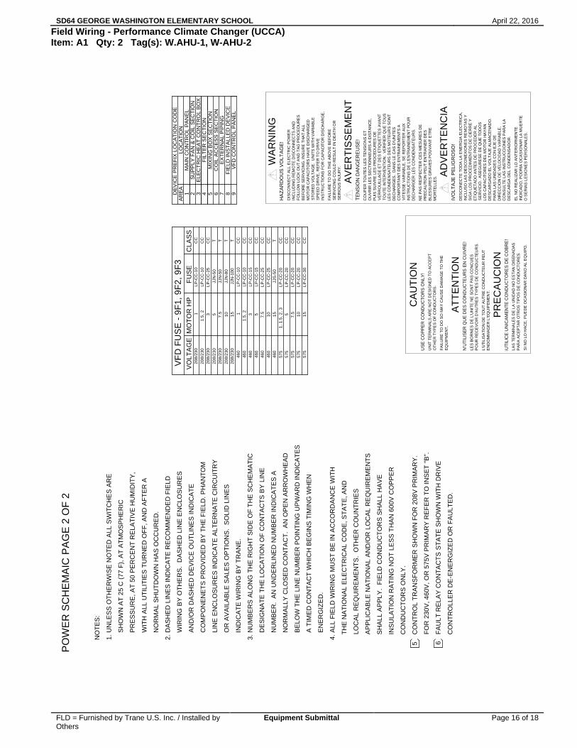
Field Wiring - Performance Climate Changer (UCCA) Item: A1 Qty: 2 Tag(s): W.AHU-1, W-AHU-2
NO
TE
S:
1. U
NLE
SS
OT
HE
RW
ISE
NO
TE
D A
LL S
WIT
CH
ES
AR
E
S
HO
WN
AT
25
C (
77 F
), A
T A
TM
OS
PH
ER
IC
P
RE
SS
UR
E, A
T 5
0 P
ER
CE
NT
RE
LAT
IVE
HU
MID
ITY
,
W
ITH
ALL
UT
ILIT
IES
TU
RN
ED
OF
F, A
ND
AF
TE
R A
N
OR
MA
L S
HU
TD
OW
N H
AS
OC
CU
RE
D.
2. D
AS
HE
D L
INE
S IN
DIC
AT
E R
EC
OM
ME
ND
ED
FIE
LD
WIR
ING
BY
OT
HE
RS
. D
AS
HE
D L
INE
EN
CLO
SU
RE
S
AN
D/O
R D
AS
HE
D D
EV
ICE
OU
TLI
NE
S IN
DIC
AT
E
CO
MP
ON
EN
ET
S P
RO
VID
ED
BY
TH
E F
IELD
. PH
AN
TO
M
LIN
E E
NC
LOS
UR
ES
IND
ICA
TE
ALT
ER
NA
TE
CIR
CU
ITR
Y
OR
AV
AIL
AB
LE S
ALE
S O
PT
ION
S.
SO
LID
LIN
ES
IND
ICA
TE
WIR
ING
BY
TR
AN
E.
3. N
UM
BE
RS
ALO
NG
TH
E R
IGH
T S
IDE
OF
TH
E S
CH
EM
AT
IC
DE
SIG
NA
TE
TH
E L
OC
AT
ION
OF
CO
NT
AC
TS
BY
LIN
E
NU
MB
ER
. A
N U
ND
ER
LIN
ED
NU
MB
ER
IND
ICA
TE
S A
NO
RM
ALL
Y C
LOS
ED
CO
NT
AC
T.
AN
OP
EN
AR
RO
WH
EA
D
BE
LOW
TH
E L
INE
NU
MB
ER
PO
INT
ING
UP
WA
RD
IND
ICA
TE
S
A T
IME
D C
ON
TA
CT
WH
ICH
BE
GIN
S T
IMIN
G W
HE
N
EN
ER
GIZ
ED
.
4. A
LL F
IELD
WIR
ING
MU
ST
BE
IN A
CC
OR
DA
NC
E W
ITH
TH
E N
AT
ION
AL
ELE
CT
RIC
AL
CO
DE
, ST
AT
E, A
ND
LOC
AL
RE
QU
IRE
ME
NT
S.
OT
HE
R C
OU
NT
RIE
S
AP
PLI
CA
BLE
NA
TIO
NA
L A
ND
/OR
LO
CA
L R
EQ
UIR
EM
EN
TS
SH
ALL
AP
PLY
. F
IELD
CO
ND
UC
TO
RS
SH
ALL
HA
VE
INS
ULA
TIO
N R
AT
ING
NO
T L
ES
S T
HA
N 6
00V
CO
PP
ER
CO
ND
UC
TO
RS
ON
LY.
CO
NT
RO
L T
RA
NS
FO
RM
ER
SH
OW
N F
OR
208
V P
RIM
AR
Y.
FO
R 2
30V
, 460
V, O
R 5
75V
PR
IMA
RY
RE
FE
R T
O IN
SE
T "
B".
5
DE
VIC
E P
RE
FIX
LO
CA
TIO
N C
OD
EA
RE
A1
MA
IN C
ON
TR
OL
PA
NE
L2
SU
PP
LY F
AN
& C
OIL
SE
CT
ION
3F
ILT
ER
SE
CT
ION
4M
IXIN
G B
OX
SE
CT
ION
5C
OIL
AC
CE
SS
SE
CT
ION
6E
XT
ER
NA
L P
IPIN
G7
FIE
LD IN
ST
ALL
ED
DE
VIC
E8
VF
D C
ON
TR
OL
PA
NE
L9
LOC
AT
ION
ELE
CT
RIC
HE
AT
CO
NT
RO
L B
OX
MO
TO
R H
PV
OLT
AG
EF
US
EC
LAS
S2
08/2
30
1L
P-C
C-1
0C
C20
8/2
301.
5, 2
LP-C
C-1
0C
C2
08/2
30
3L
P-C
C-2
5C
C20
8/2
30
5JJ
N-5
0T
208
/23
07
.5JJ
N-5
0T
208/
230
10JJ
N-8
0T
208
/23
01
5JJ
N-1
00
T4
60
1L
P-C
C-1
0C
C46
01.
5, 2
LP-C
C-1
0C
C4
603
LP
-CC
-15
CC
460
5L
P-C
C-1
5C
C4
60
7.5
LP
-CC
-25
CC
460
10LP
-CC
-25
CC
460
15
JJS
-50
T57
51,
1.5
, 2, 3
LP-C
C-2
0C
C5
755
LP
-CC
-20
CC
575
7.5
LP-C
C-2
0C
C5
751
0L
P-C
C-2
0C
C5
75
15
LP
-CC
-30
CC
VF
D F
US
E -
9F
1, 9
F2,
9F
3
6
CO
NT
RO
LLE
R D
E-E
NE
RG
IZE
D O
R F
AU
LTE
D.
FA
ULT
RE
LAY
CO
NT
AC
TS
ST
AT
E S
HO
WN
WIT
H D
RIV
E
PO
WE
R S
CH
EM
AIC
PA
GE
2 O
F 2
FA
ILU
RE
TO
DO
SO
MA
Y C
AU
SE
DA
MA
GE
TO
TH
E
UN
IT T
ER
MIN
ALS
AR
E N
OT
DE
SIG
NE
D T
O A
CC
EP
T
N'U
TIL
ISE
R Q
UE
DE
S C
ON
DU
CT
EU
RS
EN
CU
IVR
E!
LES
BO
RN
ES
DE
L'U
NIT
E N
E S
ON
T P
AS
CO
NC
UE
SP
OU
R R
EC
EV
OIR
D'A
UT
RE
S T
YP
ES
DE
CO
ND
UC
TE
UR
S.
L'U
TIL
ISA
TIO
N D
E T
OU
T A
UT
RE
CO
ND
UC
TE
UR
PE
UT
SI N
O L
O H
AC
E, P
UE
DE
OC
AS
ION
AR
DA
NO
AL
EQ
UIP
O.
PA
RA
AC
EP
TA
R O
TR
OS
TIP
OS
DE
CO
ND
UC
TO
RE
S.
LAS
TE
RM
INA
LES
DE
LA
UN
IDA
D N
O E
ST
AN
DIS
EN
AD
AS
iUT
ILIC
E U
NIC
AM
EN
TE
CO
ND
UC
TO
RE
S D
E C
OB
RE
!
EN
DO
MM
AG
ER
L'E
QU
IPE
ME
NT
.
PR
EC
AU
CIO
N
OT
HE
R T
YP
ES
OF
CO
ND
UC
TO
RS
.
EQ
UIP
ME
NT
.
AT
TE
NT
ION
US
E C
OP
PE
R C
ON
DU
CT
OR
S O
NLY
!
CA
UT
ION
INC
LUD
ING
RE
MO
TE
DIS
CO
NN
EC
TS
AN
D
AV
ER
TIS
SE
ME
NT
AD
VE
RT
EN
CIA
NE
PA
S R
ES
PE
CT
ER
CE
S M
ES
UR
ES
DE
FO
LLO
W L
OC
K O
UT
AN
D T
AG
PR
OC
ED
UR
ES
BE
FO
RE
SE
RV
ICIN
G. I
NS
UR
E T
HA
T A
LLM
OT
OR
CA
PA
CIT
OR
S H
AV
E D
ISC
HA
RG
ED
ST
OR
ED
VO
LTA
GE
. U
NIT
S W
ITH
VA
RIA
BLE
INS
TR
UC
TIO
NS
FO
R C
AP
AC
ITO
R D
ISC
HA
RG
E.
SE
RV
ICIN
G C
OU
LD R
ES
ULT
IN D
EA
TH
OR
INS
TR
UC
TIO
NS
DE
L'E
NT
RA
INE
ME
NT
PO
UR
VIT
ES
SE
VA
RIA
BLE
, SE
RE
PO
RT
ER
AU
X
DE
CH
AR
GE
S.
DA
NS
LE
CA
S D
'UN
ITE
SLE
S C
ON
DE
NS
AT
EU
RS
DE
S M
OT
EU
RS
SO
NT
TO
UT
E IN
TE
RV
EN
TIO
N.
VE
RIF
IER
QU
E T
OU
SV
ER
RO
UIL
LAG
E E
T D
ES
ET
IQU
ET
TE
S A
VA
NT
OU
VR
IR L
ES
SE
CT
ION
NE
UR
S A
DIS
TA
NC
E,
PR
EC
AU
TIO
N P
EU
T E
NT
RA
INE
R D
ES
BLE
SS
UR
ES
GR
AV
ES
PO
UV
AN
T E
TR
E
DE
CH
AR
GE
R L
ES
CO
ND
EN
SA
TE
UR
S.
MO
RT
ELL
ES
.
TE
NS
ION
DA
NG
ER
EU
SE
!
SP
EE
D D
RIV
E, R
EF
ER
TO
DR
IVE
FA
ILU
RE
TO
DO
TH
E A
BO
VE
BE
FO
RE
CO
MP
OR
TA
NT
DE
S E
NT
RA
INE
ME
NT
S A
PU
IS S
UIV
RE
LE
S P
RO
CE
DU
RE
S D
E
CO
UP
ER
TO
UT
ES
LE
S T
EN
SIO
NS
ET
SE
RIO
US
INJU
RY
.WA
RN
ING
DIS
CO
NN
EC
T A
LL E
LEC
TR
IC P
OW
ER
HA
ZA
RD
OU
S V
OLT
AG
E!
CO
NS
ULT
E L
AS
INS
TR
UC
CIO
NE
S P
AR
A L
AD
IRE
CC
ION
DE
VE
LOC
IDA
D V
AR
IAB
LE,
PA
RA
LA
S U
NID
AD
ES
CO
N E
JE D
E
SE
RV
ICIO
. A
SE
GU
RE
SE
DE
QU
E T
OD
OS
ET
IQU
ET
AD
O A
NT
ES
DE
PR
OC
ED
ER
AL
SIG
A L
OS
PR
OC
ED
IMIE
NT
OS
DE
CIE
RR
E Y
INC
LUS
O L
AS
DE
SC
ON
EX
ION
ES
RE
MO
TA
S Y
O S
ER
IAS
LE
SIO
NE
S P
ER
SO
NA
LES
.IN
DIC
AD
O, P
OD
RIA
OC
AS
ION
AR
LA
MU
ER
TE
EL
NO
RE
ALI
ZA
R L
O A
NT
ER
IOR
ME
NT
E
DE
SC
AR
GA
DE
L C
ON
DE
NS
AD
OR
.
LOS
CA
PA
CIT
OR
ES
DE
L M
OT
OR
HA
YA
N
iVO
LTA
JE P
ELI
GR
OS
O!
DE
SC
AR
GA
DO
EL
VO
LTA
JE A
LMA
CE
NA
DO
.
DE
SC
ON
EC
TE
TO
DA
LA
EN
ER
GIA
ELE
CT
RIC
A,
SD64 GEORGE WASHINGTON ELEMENTARY SCHOOL April 22, 2016
FLD = Furnished by Trane U.S. Inc. / Installed by Others
Equipment Submittal Page 17 of 18
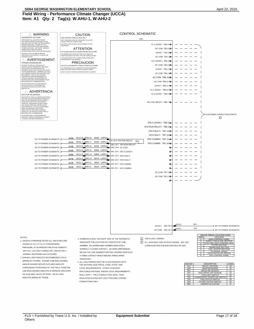
Field Wiring - Performance Climate Changer (UCCA) Item: A1 Qty: 2 Tag(s): W.AHU-1, W-AHU-2
DEVICE PREFIX LOCATION CODEAREA
1 MAIN CONTROL PANEL2 SUPPLY FAN & COIL SECTION3
FILTER SECTION4MIXING BOX SECTION5
COIL ACCESS SECTION6EXTERNAL PIPING7
FIELD INSTALLED DEVICE8VFD CONTROL PANEL9
LOCATION
ELECTRIC HEAT CONTROL BOX
NOTES:
1. UNLESS OTHERWISE NOTED ALL SWITCHES ARE
SHOWN AT 25 C (77 F), AT ATMOSPHERIC
PRESSURE, AT 50 PERCENT RELATIVE HUMIDITY,
WITH ALL UTILITIES TURNED OFF, AND AFTER A
NORMAL SHUTDOWN HAS OCCURED.
2. DASHED LINES INDICATE RECOMMENDED FIELD
WIRING BY OTHERS. DASHED LINE ENCLOSURES
AND/OR DASHED DEVICE OUTLINES INDICATE
COMPONENETS PROVIDED BY THE FIELD. PHANTOM
LINE ENCLOSURES INDICATE ALTERNATE CIRCUITRY
OR AVAILABLE SALES OPTIONS. SOLID LINES
INDICATE WIRING BY TRANE.
USE CLASS 2 WIRING.
ALL AVAILABLE END DEVICES SHOWN. SEE UNIT
CONFIGURATION FOR END DEVICES ON UNIT.
GO TO POWER SCHEMATIC
GO TO POWER SCHEMATIC
GO TO POWER SCHEMATIC
GO TO POWER SCHEMATIC
GO TO POWER SCHEMATIC
GO TO POWER SCHEMATIC
GO TO POWER SCHEMATIC
GO TO POWER SCHEMATIC
GO TO POWER SCHEMATIC
GO TO POWER SCHEMATIC
ZONEDESCRIPTIONDEVICE
47DAMPER ACTUATOR5M161FILTER STATUS SWITCH2S459FAN STATUS SWITCH2S357CONDENSATE OVERFLOW SWITCH2S255LOW LIMIT SWITCH2S153DISCHARGE AIR SENSOR2R251MIXED AIR SENSOR2R134ADAPTER BOARD1W140RELAY; VFD RUN1K1
VFD COMM5- TB7-10
VFD COMM5+ TB7-11
VFD FAULT- TB7-12
VFD FAULT+ TB7-13
VFD RUN RELAY+ TB6-1
VFD 0-10VDC+ TB6-2
AC COM TB6-13
401A
402A
407A
408A
409A
410A
404A
403A9XP1-8
9XP1-7
9XP1-6
9XP1-5
9XP1-4
9XP1-3
9XP1-2
9XP1-1
9XJ1-8
9XJ1-7
9XJ1-6
9XJ1-5
9XJ1-4
9XJ1-3
9XJ1-2
9XJ1-1
1XP5-8
1XP5-7
1XP5-6
1XP5-5
1XP5-4
1XP5-3
1XP5-2
1XP5-1
1W1 J3-8
1W1 J3-7
1W1 J3-6
1W1 J3-5
1W1 J3-4
1W1 J3-3
1W1 J3-2
1W1 J3-1
1K1
401B
402B
407B
408B
409B
410B
404B
403B
VFD COMM5+
VFD COMM5-
VFD FAULT+
VFD FAULT-
VFD 0-10VDC+
DC COM
VFD RUN RELAY+
VFD RUN RELAY-
AC COM
24VAC+YEL
1W1 J5-1
1W1 J5-2
1XP3-1
1W1
V1 2-10VDC+ TB4-4
DC COM TB4-3
24VAC+ TB4-2
AC COM TB4-1
V2 2-10VDC+ TB5-4
DC COM TB5-3
MC COIL RELAY+ TB6-7
CUSTOMER CONNECTION POINTS
5
4. ALL FIELD WIRING MUST BE IN ACCORDANCE WITH
3. NUMBERS ALONG THE RIGHT SIDE OF THE SCHEMATIC
DESIGNATE THE LOCATION OF CONTACTS BY LINE
NUMBER. AN UNDERLINED NUMBER INDICATES A
NORMALLY CLOSED CONTACT. AN OPEN ARROWHEAD
BELOW THE LINE NUMBER POINTING UPWARD INDICATES
A TIMED CONTACT WHICH BEGINS TIMING WHEN
ENERGIZED.
5
6
BLU 1XP3-2
DC COM TB7-2
DC COM TB7-3
24VAC+ TB5-2
AC COM TB5-1
AC COM TB6-12
24VAC+ TB6-11
V1 2-10VDC+ TB6-10
V2 2-10VDC+ TB6-9
THE NATIONAL ELECTRICAL CODE, STATE, AND
LOCAL REQUIREMENTS. OTHER COUNTRIES
APPLICABLE NATIONAL AND/OR LOCAL REQUIREMENTS
SHALL APPLY. FIELD CONDUCTORS SHALL HAVE
INSULATION RATING NOT LESS THAN 600V COPPER
CONDUCTORS ONLY.
DEVICE PREFIX LOCATION CODEDEVICE PREFIX LOCATION CODEDEVICE PREFIX LOCATION CODE
FAILURE TO DO SO MAY CAUSE DAMAGE TO THE
UNIT TERMINALS ARE NOT DESIGNED TO ACCEPT
N'UTILISER QUE DES CONDUCTEURS EN CUIVRE!
LES BORNES DE L'UNITE NE SONT PAS CONCUESPOUR RECEVOIR D'AUTRES TYPES DE CONDUCTEURS.
L'UTILISATION DE TOUT AUTRE CONDUCTEUR PEUT
SI NO LO HACE, PUEDE OCASIONAR DANO AL EQUIPO.
PARA ACEPTAR OTROS TIPOS DE CONDUCTORES.LAS TERMINALES DE LA UNIDAD NO ESTAN DISENADAS
iUTILICE UNICAMENTE CONDUCTORES DE COBRE!
ENDOMMAGER L'EQUIPEMENT.
PRECAUCION
OTHER TYPES OF CONDUCTORS.
EQUIPMENT.
ATTENTION
USE COPPER CONDUCTORS ONLY!
CAUTION
INCLUDING REMOTE DISCONNECTS AND
AVERTISSEMENT
ADVERTENCIA
NE PAS RESPECTER CES MESURES DE
FOLLOW LOCK OUT AND TAG PROCEDURESBEFORE SERVICING. INSURE THAT ALLMOTOR CAPACITORS HAVE DISCHARGEDSTORED VOLTAGE. UNITS WITH VARIABLE
INSTRUCTIONS FOR CAPACITOR DISCHARGE.
SERVICING COULD RESULT IN DEATH OR
INSTRUCTIONS DE L'ENTRAINEMENT POURVITESSE VARIABLE, SE REPORTER AUX
DECHARGES. DANS LE CAS D'UNITESLES CONDENSATEURS DES MOTEURS SONTTOUTE INTERVENTION. VERIFIER QUE TOUSVERROUILLAGE ET DES ETIQUETTES AVANT
OUVRIR LES SECTIONNEURS A DISTANCE,
PRECAUTION PEUT ENTRAINER DESBLESSURES GRAVES POUVANT ETRE
DECHARGER LES CONDENSATEURS.
MORTELLES.
TENSION DANGEREUSE!
SPEED DRIVE, REFER TO DRIVE
FAILURE TO DO THE ABOVE BEFORE
COMPORTANT DES ENTRAINEMENTS A
PUIS SUIVRE LES PROCEDURES DE
COUPER TOUTES LES TENSIONS ET
SERIOUS INJURY.
WARNING
DISCONNECT ALL ELECTRIC POWER
HAZARDOUS VOLTAGE!
CONSULTE LAS INSTRUCCIONES PARA LADIRECCION DE VELOCIDAD VARIABLE,PARA LAS UNIDADES CON EJE DE
SERVICIO. ASEGURESE DE QUE TODOSETIQUETADO ANTES DE PROCEDER ALSIGA LOS PROCEDIMIENTOS DE CIERRE YINCLUSO LAS DESCONEXIONES REMOTAS Y
O SERIAS LESIONES PERSONALES.INDICADO, PODRIA OCASIONAR LA MUERTEEL NO REALIZAR LO ANTERIORMENTE
DESCARGA DEL CONDENSADOR.
LOS CAPACITORES DEL MOTOR HAYAN
iVOLTAJE PELIGROSO!
DESCARGADO EL VOLTAJE ALMACENADO.
DESCONECTE TODA LA ENERGIA ELECTRICA,
CONTROL SCHEMATIC
SD64 GEORGE WASHINGTON ELEMENTARY SCHOOL April 22, 2016
FLD = Furnished by Trane U.S. Inc. / Installed by Others
Equipment Submittal Page 18 of 18
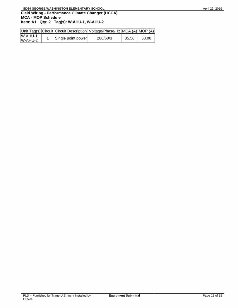
Field Wiring - Performance Climate Changer (UCCA) MCA - MOP Schedule Item: A1 Qty: 2 Tag(s): W.AHU-1, W-AHU-2
Unit Tag(s)
Circuit
Circuit Description
Voltage/Phase/Hz
MCA (A)
MOP (A)
W.AHU-1, W-AHU-2 1 Single point power
208/60/3 35.50 60.00