Embed Size (px)
Citation preview

NIBE™ F750 Exhaust aIr hEat pump
NIBE F750NIBE F750 is a complete exhaust air heat pump for both new instal-lations and replacement in houses or similar.
It has an integrated DC fan and water heater that has stainless steel corrosion protection. there is an integrated immersion heater used as an additional heater when it becomes really cold outside.
Energy is recovered from the ventilation air and supplied to the heat pump, which reduces energy costs considerably. the device venti-lates the house, supplies heat and produces domestic hot water. NIBE F750 is intended for low temperature dimensioned radiator circuits and/or under floor heating.
the heat pump works based on the floating condensing principle, and is why the boiler section has a 25 litre temperature buffer ves-sel. NIBE F750 should not be docked to other heat sources.
Colourful exhaust
• Energyandpowerefficientexhaustairheatpumpwithinvertercontrolledcompressor
• Displayunitwitheasy-to-readcolourscreen
• Specifiedcompressoroutput1.5-6.0kW
• Extractairtemperaturedownto-15°C
• Lowenergyfan
• Lowenergycirculationpump,classA
• Outdoortemperaturesensor/indoortemperaturesensor
• Measuresandlogsaverageindoortemperatureduringtheheatingseason
• Schedulingheating,ventilationandhotwateraswellasholidaymode
• Cancontroluptofourheatingsystems,withdifferenttemperaturelevels
• Phaseindividualloadmonitor
• CancommunicatewithGSM(accessory)
• Integratedvolumevesselof25l

2 NIBE F750
how do exhaust air heat pumps work?
Ventilation, which means totally hygienic inside air, is a basic requirement for living in a healthy house. Controlled domestic ventilation with heat recovery reuses the energy from the exhaust air.
1. Warm exhaust air is blown across the heat
exchange and the heat is transferred into
the refrigerant circuit. the cold exhaust air
passes to the outside of the house.
2. the compressor raises the pressure of the
refrigerant, resulting in an increase in
temperature in the heat pump.
3. Energy extracted from the exhaust air is
transferred into a water-based heating system to
heat your home and hot water.
4. In the condenser, the refrigerant reverts to liquid
form, ready to turn into gas once more and to
collect new heat energy.80 °C
22 °C0 °C
10 °C 0 °C
55 °C45 °C
Heat carrier
Cooling medium
Refrigerant
Evaporator
Condenser
Expansion Valve Compressor
Heat source
1
2
34
80 °C
22 °C0 °C
10 °C 0 °C
55 °C45 °C
Förångare
Kondensor
Expansionsventil Kompressor
Värmekälla
1
2
34
Värmebärare
Köldbärare
Köldmedium
80 °C
22 °C0 °C
10 °C 0 °C
55 °C45 °C
Heat carrier
Cooling medium
Refrigerant
Evaporator
Condenser
Expansion Valve Compressor
Heat source
1
2
34
80 °C
22 °C0 °C
10 °C 0 °C
55 °C45 °C
Förångare
Kondensor
Expansionsventil Kompressor
Värmekälla
1
2
34
Värmebärare
Köldbärare
Köldmedium
Condensor
CompressorExpansion valve
heat source
Evaporator
heat source
refrigerant
Cooling medium
-15°C -5°C
-15°C
100°C

good to know about nibe™ f750
Transport and storageF750 should be transported and stored vertically and stored in a dry place.
Designa microprocessor controls F750. this makes for easy operation at the same time as always enabling the heat pump to run as ef-ficiently as possible, as the microprocessor continuously decides the best method of operation. the microprocessor also manages the heating automatic device and circulation pump. It is possible to control an automatic bypass when there is a need of two dif-ferent flow temperatures. the numerical display shows the cur-rent temperatures and set values in plain text.
the design of the ventilation section gives a high ventilation ca-pacity. the steplessly reconnectable fan steps can easily be in-creased or reduced via the internal clock, control panel or exter-nal signal.
F750 gives great savings thanks to a powerful, variable compres-sor, which, with intelligent control, works with the most favour-able temperature conditions.
the insulation consists of moulded Neopor (environmentally friendly cellular plastic) for minimal heat loss.
the outer casing is of white powder coated steel plate. the front door is easy to remove for easy access when installing and for servicing.
F750 has a maximum immersion heater output of 6.5 kW. the output is easy to adjust via the display and can be blocked if needed.
EquipmentNIBE F750 is equipped with a complete set of valves, consisting of a drain valve, filling valve, non-return valve, and safety valve for the water heater section. the boiler section is equipped with a drain valve, filling valve and safety valve. In addition, the unit is equipped with climate controlled heating automatic devices with outdoor temperature, indoor temperature and flow sensors, circulation pump, load monitor and expansion vessel.
R
0
+ 20-2
1
R
0
H M flo w4 9 (5 0 ) °CH o t w a te r 5 1 °C
+20
-2
1 R0
HM
flow4
9 (5
0) °C
Hot
wate
r51 °C
R0

4 NIBE F750
good to know about nibe™ f750
New buildsF750 has been developed to meet energy and output require-ments for new buildings.
Exhaust air
NIBE F750 has a large, powerful compressor that can fulfil the output and energy requirement in accommodations up to and around 200 square metres (depending on the design and ge-ograpic location of the house). as the compressor is inverter con-trolled, operation is very economical and the output two to three times higher than for conventional exhaust air models.
Over and above this, you get all the normal advantages of ex-haust air heating systems – no boreholes required and the system is supplied as one complete unit that supplies the accommoda-tion with heat, hot water and ventilation.
Ground-source heating
If you build a house that is larger than average and/or if you have an outdoor pool and/or heated garage, we recommend a ground-source heat pump, e.g. NIBE F1245.
kW
Hours0
2
4
6
8
0
Heat pump
Energy needs covered by heat pump
Energy needs covered by immersion heater
1000 2000 3000 4000 5000 6000 7000 8000
kW
Hours0
2
4
6
8
0
Heat pump
Energy needs covered by heat pump
Energy needs covered by immersion heater
1000 2000 3000 4000 5000 6000 7000 8000
Conventional exhaust air heat pumpthe proportion of the accommodation’s energy demand that can be provided by a traditional exhaust air heat pump is shown below.
Exhaust air heat pump NIBE F750Note how the outgoing output from NIBE F750 follows the curve for the building’s energy demand. this is possible thanks to the heat pump’s powerful inverter controlled compressor.
Ground source heat pumpthis diagram shows how much energy a ground-source heat pump can generate. savings are large, but this type of heat pump would generate too much energy for a small house, which in-creases the risk of malfunctions and would make the compressor start and stop frequently, which, in turn, shortens the service life of the compressor.
kW
Hours0
2
4
6
8
0 1000 2000 3000 4000 5000 6000 7000 8000
Heat pump
Energy needs covered by heat pump
Energy needs covered by immersion heater

Dimensions
pipework from below, is not allowed within
hatched area.
NIBE F750 5
120
57
600
614
313
58
35
442
25-
50
370
350
440180
120
207
5
Ø125 Ø125
good to know about nibe™ f750

6 NIBE F750
good to know about nibe™ f750
Equipment
LEK
LEK
/ APH
LEK
LEK
PBD SV
XL32
XL31
QA40
X101
RF2
RA1
LEK
Bp1
xL8
hZ2
xL2
Cm1
Qm10
FL6
Fa1
aa1
FD1
EB1
Bt30
pF3
pF1
Bt63
Bt7
QN10
aa101
Qm24
Bt14
Bt62
Bt15
Gp1
xL10
Bp2
xL5
Bt12
xL3
FQ1
GQ10
rm1
Bt3
Qm11
xL4 FL1 Qm23 Qm20 Qm22
Wm1
Wm2
FL2
Wp3
aa2
Bp5
Bt6
aa3
aa4-xJ3
aa4-xJ3
sF1
aa4
uB2
uB1
Bt16
Ep1
QN1
Bt20
Bt17
Bs1
ur1GQ2
Wp1 Wp2 Bt61 Gp6
Ep2
xL1
Bt21
Qm31

NIBE F750 7
List of componentsPipe connections
xL1 Connection, heating medium flow line
xL2 Connection, heating medium return line
xL3 Connection, cold water
xL4 Connection, hot water
xL5 Connection, hot water circulation
xL8 Connection, docking in
xL10 Connection, draining heating medium
xL31 Ventilation connection, exhaust air
xL32 Ventilation connection, extract air
HVAC components
Cm1 Expansion vessel
FL1 safety valve, water heater
FL2 safety valve, climate system
FL 6 Vacuum valve
FQ 1 mixer valve, hot water
Gp1 heating medium pump
Gp6 heating medium pump 2
Qm10 Filling valve, water heater
Qm 11 Filler valve, climate system
Qm20 Venting, climate system
Qm22 Venting, coil
Qm23 Venting, buffer tank
Qm24 Venting, exchanger
Qm31 shut-off valve, heating medium flow
QN10 reversing valve, climate system/water heater
rm1 Non-return valve
Wm1 Drip tray
Wm2 Overflow water discharge
Wp 1 Overflow pipe, safety valve hot water heater
Wp 2 Overflow pipe, safety valve climate system
Wp 3 Condensation lead off, fan box
Sensors etc.
Bp 1 high pressure pressostat
Bp 2 Low pressure pressostat
Bp5 pressure gauge, heating system
Bs1 air speed sensor
Bt 3 temperature sensors, heating medium return
Bt 6 temperature sensor, hot water, control
Bt 7 temperature sensor, hot water, display
Bt 12 temperature sensor, heating medium flow after
condenser
Bt 14 temperature sensor, hot gas
Bt 15 temperature sensor, fluid pipe
Bt 16 temperature sensor, evaporator
Bt 17 temperature sensor, suction gas
Bt 20 temperature sensor, exhaust air
Bt 21 temperature sensor, extract air
Bt 30 thermostat, backup heating
Bt 61 temperature sensor, heating medium flow after buffer vessel
Bt 62 temperature sensor, heating medium return after buffer vessel
Bt 63 temperature sensor, heating medium supply after immersion heater
Electrical components
aa1 Immersion heater card
aa2 Base card
aa3 Input circuit board
aa 4 Display unit
aa4-xJ3 usB socket
aa4-xJ4 service socket
aa101 Connection card sensor
EB1 Immersion heater
Fa1 miniature circuit-breaker
FD1 temperature limiter
Qa40 Inverter
ra1 Choke
rF2 EmC-filter
sF1 switch
x101 terminal fuse, inverter
Cooling components
Ep1 Evaporator
Ep2 Condenser
GQ10 Compressor
hZ2 Drying filter with tank *
QN1 Expansion valve *
Ventilation
GQ2 Exhaust air fan
ur1 Filter cover
Miscellaneous
pF1 type plate
pF3 serial number plate
uB1 Cable grommet
uB2 Cable grommet
* Not visable in the image.
Designations in component locations according to standard IEC 81346-1 and 81346-2.
good to know about nibe™ f750

8 NIBE F750
installation
Installation and positioningto facilitate pipe installation, a space should be left for the distri-bution manifold etc on the right or left-hand side. For other in-stallation dimensions, see “Dimensions”.
the heat pump should preferably be erected with its back about 10 mm from an outside wall in a utility room or similar, to mini-mise noise nuisance. If this is not possible, avoid using a wall that backs on to a bedroom or some other room where noise would be a problem. Wherever the unit is placed, any wall that backs on to a bedroom should be fitted with sound insulation. Note! the distance between the heat pump and the wall should be at least 10 mm.
route pipes so they are not fixed to an internal wall that backs on to a bedroom or living room.
the heat pump’s installation area should always have a tempera-ture of at least 10 °C and max 30 °C.
Pipe installationpipe installation must be carried out in accordance with current norms and directives.
Four flexible connection pipes with quick-release connectors are supplied with the product for quick and easy installation.
Radiator connection
When the circulation pump is operating the flow in the heat-ing system must not be stopped completely, i.e. at least one of the heating system’s radiators/under floor heating loops must be fully open.
Tap water connection
the heat pump should be supplemented with an external water heater if a bubble pool or other significant consumer of hot wa-ter is installed.
Water heater without immersion heater
For new builds water heater type NIBE VpB 200 or VpBs 300 (prepared for solar docking) are used. the docking kit accessory is not required. place VpB 200 to the left of F750. VpBs 300 re-quires pipe routing behind the units, which requires 60 mm of free space to the wall.
Water heater with immersion heater
For existing houses NIBE Compact or Eminent type water heat-ers can be used.
For more information see www.nibe.eu.
(50) (50)
Installation areaLeave a space of 500 mm in front of the heat pump. approxi-mately 50 mm free space is required on each side in order to open the side hatches. the hatches do not need to be opened during service, all service on F750 can be carried out from the front.
Leave space between the heat pump and wall behind (and any routing of supply cables and pipes) to reduce the risk reproduc-tion of any vibration.
500
NOtE!Ensure that there is sufficient space (300 mm) above the heat pump for installing ventilation hoses.

NIBE F750 9
the requisite circuit fuse is based on the table below.
Other electrical equipment is connected at the factory, except the outdoor and indoor temperature sensors. Operation (230V), fan and circulation pumps are internally fused by a miniature circuit breaker (10a).
Electrical addi-tion (kW)
max (a) L1 max (a) L2 max (a) L3
2 2 0 8,7
5 9,5 7,5 8,7
6,5 11,7 11,8 8,7
the table shows max phase current (operating 230 V, electrical addition, fan and circulation pumps) at the different power steps for the heat pump.
In addition to this there is the current for the compressor, which may amount to 4.3 a on all phases, depending on operation.
Output locking
maximum power output (maximum installed electrical output) can be locked. to then change the maximum power output, the display card must be replaced.
InspectionF750 is equipped with a closed expansion vessel as standard. Cur-rent norms require the heating installation to be inspected before it is commissioned. this inspection should only be made by per-sons with the necessary expertise.
Function checks of the ventilation system must be carried out by authorised persons according to the applicable regulation.
Tryckfall värmebärarpump 2 (GP6)Hastighet I
120130140
110100
8090
706050403020100
0,050 0,10 0,15 0,20
Flöde (l/s)
0,25 0,30 0,35 0,40 0,45 0,50
Tillgängligt tryck(kPa)
Tryckfall värmebärarpump 2 (GP6)Hastighet II
120130140
110100
8090
706050403020100
0,050 0,10 0,15 0,20
Flöde (l/s)
0,25 0,30 0,35 0,40 0,45 0,50
Tillgängligt tryck(kPa)
120130140
110100
8090
706050403020100
0,050 0,10 0,15 0,20
Flöde (l/s)
0,25 0,30 0,35 0,40 0,45 0,50
Tillgängligt tryck(kPa)
Tryckfall värmebärarpump 2 (GP6)Hastighet III
installation
Electrical connectionsConnection must not be carried out without the permission of the electricity supplier and must be under the supervision of a qualified electrician.
F750 must be connected with corresponding connection cable (length 2 m) via an isolator switch with a minimum breaking gap of 3 mm. the connection cable can be found on the reverse of F750 (see image below).
Maximum boiler and radiator volumesthe volume of the expansion vessel is 10 litres and it is pressur-ised as standard to 0.5 bar (5 mvp). as a result, the maximum height between the vessel and the highest radiator is 5 metres. there is a valve on the vessel for any pre-pressure adjustment.
the initial pressure of the expansion vessel must be stated in the inspection document.
the maximum system volume at the above pre-pressure, exclud-ing the boiler, is 260 litres.
Available external pressure, climate system
50
300
30
x
pressure drop (kpa)
pressure drop (kpa)
Speed 1
Flow (l/s)
Speed 2
Speed 3
pressure drop (kpa)

10 NIBE F750
installation
Setting the fan capacityselect the ventilation capacity in the display.
Fan diagramthe diagram below show the available ventilation capacity. min exhaust air flow is 31 l/s (110 m3/h).
500
450
400
350
300
250
200
150
100
50
00 14 28 42 56
Flöde l/s)70 84 98 112
Till-gängligt
tryck(Pa)
30%
60%
90%
100%
40%50%
70%80%
pressure drop (kpa)
Flow (l/s)
Outdoor and room temperature sensors Connect the sensors with two-core cable to terminal block. the minimum cable cross section should be 0.4 mm2 up to lengths of 50 metres, for example, EKKx or LiYY.
Install the outdoor temperature sensor in the shade on a wall fac-ing north or north-west, so it is unaffected by the morning sun. If a conduit is used it must be sealed to prevent condensation in the sensor capsule.
Install the room temperature sensor in a neutral position where the shown temperature is required.
VentilationF750 is connected so that all ventilation air except the kitchen fan passes the evaporator in the heat pump. For optimum heat pump operation the ventilation flow must not fall below 110 m3/h (31 l/s). Even if the norm requirements give lower flow requirements, the increase to 110 m3/h does not mean an increase in energy consumption as the heat pump level of recovery also increases.
Connections must be made via flexible hoses, which must be in-stalled so that they are easy to replace. Because the extract air can reach -15 °C, the extract air duct must be insulated with diffusion proof material (pE30) over its entire length. Exhaust air ducts that are laid in cold areas must be insulated. provision must be made for inspection of the duct. make sure that there are no reductions of cross-sectional area in the form of creases, tight bends etc, since this will reduce the ventilation capacity. all joins in the duct-ing must be sealed and pop-riveted to prevent leakage. the duct system must be carried out in accordance with current norms. a minimum of air tightness class B is recommended.
the extract air duct should, if possible, be routed up through the roof. If the duct is to be routed out through the roof, avoid having a 90 degree bend backward, as this can cause noise and poorer capacity.
to prevent fan noise being transferred to the exhaust air valves, it may be a good idea to install a silencer in the duct. this is also recommended for shorter extract air ducts.
to obtain the necessary air exchange in every room of the house, the exhaust air devices must be correctly positioned and adjust-ed. a defective ventilation installation may lead to reduced heat pump efficiency and thus poorer operating economy, and may re-sult in damage to the house.
the extract air duct must not be routed to the flue.
If a stove or similar is installed, it must have sealing doors and be able to take combustion air from outside.
to achieve a good level of comfort it is also important to use a sufficient number of outdoor air devices with good air distribu-tion.

NIBE F750 11
installation
Control, generalthe indoor temperature depends on several factors. sunlight and heat emissions from people and household machines are normally sufficient to keep the house warm during the warmer parts of the year. When it gets colder outside, the climate sys-tem must be started. the colder it is outside, the warmer radia-tors and floor heating system must be.
Control of the heat production is performed based on the “floating condensing” principle, i.e. the temperature level needed for heating at a specific outdoor temperature is pro-duced guided by collected values from the outdoor and flow sensors. the room sensor can also be used to compensate the deviation in room temperature.
Heat productionthe heat supply to the building is controlled in accordance with the selected control curve (curve slope and offset) in menu 1.9.1. after adjustment, the correct amount of heat for the current outdoor temperature is supplied. the flow line tem-perature of the heat pump will hunt around the theoretically required value.
Hot water productionhot water charging starts when the hot water sensor has fallen to the set start temperature. hot water charging stops when the hot water temperature on the hot water sensor (Bt6) has been reached.
For occasional higher demand for hot water, the “temporary lux” can be used to raise the temperature for 3 – 12 hours (se-lected in the menu system).
Additional heat onlyF750 can be used with only additional heat (electric boiler) to produce heating and hot water, for example, before the venti-lation system is complete.
Alarm indicationsthe status lamp lights red in the event of an alarm and the dis-play shows detailed information depending on the fault. an alarm log is created with each alarm containing a number of temperatures, times and the status of outputs.
Own curveF750 has pre-programmed non linear heating curves. It is also possible to create an own defined curve. this is an individual linear curve with one break point. You select a break point and the associated temperatures.
USB service outletF750 is equipped with a usB socket in the display unit. this usB socket can be used to connect a usB memory to update the soft-ware, save logged information and handle the settings in F750.
SMS 40F750 can be controlled and monitored externally with accessory sms 40.
sms 40 consists of a communications module, a Gsm modem with an antenna and a separate power supply unit with jack for plugging into a wall socket. the antenna can be placed outside the enclosure.
sms 40 enables operation to be controlled and monitored, via a Gsm module, using a mobile phone via sms messages. For the Gsm function to work, the communications module must be equipped with a valid Gsm subscription. this may for example be a cash card or a special telematics subscription.
For further presentation, visit www.nibe.eu
LE
K
12 NIBE F750
F750
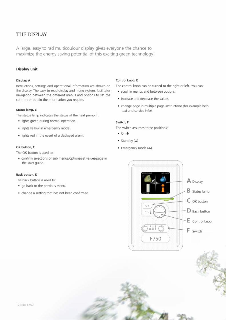
the display
Display unit
Display, A
Instructions, settings and operational information are shown on the display. the easy-to-read display and menu system, facilitates navigation between the different menus and options to set the comfort or obtain the information you require.
Status lamp, B
the status lamp indicates the status of the heat pump. It:
• lightsgreenduringnormaloperation.
• lightsyellowinemergencymode.
• lightsredintheeventofadeployedalarm.
OK button, C
the OK button is used to:
• confirmselectionsofsubmenus/options/setvalues/pageinthestartguide.
Back button, D
the back button is used to:
• gobacktothepreviousmenu.
• changeasettingthathasnotbeenconfirmed. B status lamp
A Display
C OK button
D Back button
E Control knob
F switch
Control knob, E
the control knob can be turned to the right or left. You can:
• scrollinmenusandbetweenoptions.
• increaseanddecreasethevalues.
• changepageinmultiplepageinstructions(forexamplehelptextandserviceinfo).
Switch, F
the switch assumes three positions:
• On( )
• Standby( )
• Emergencymode( )
a large, easy to rad multicoulour display gives everyone the chance to maximize the energy saving potential of this exciting green technology!
NIBE F750 13
the display
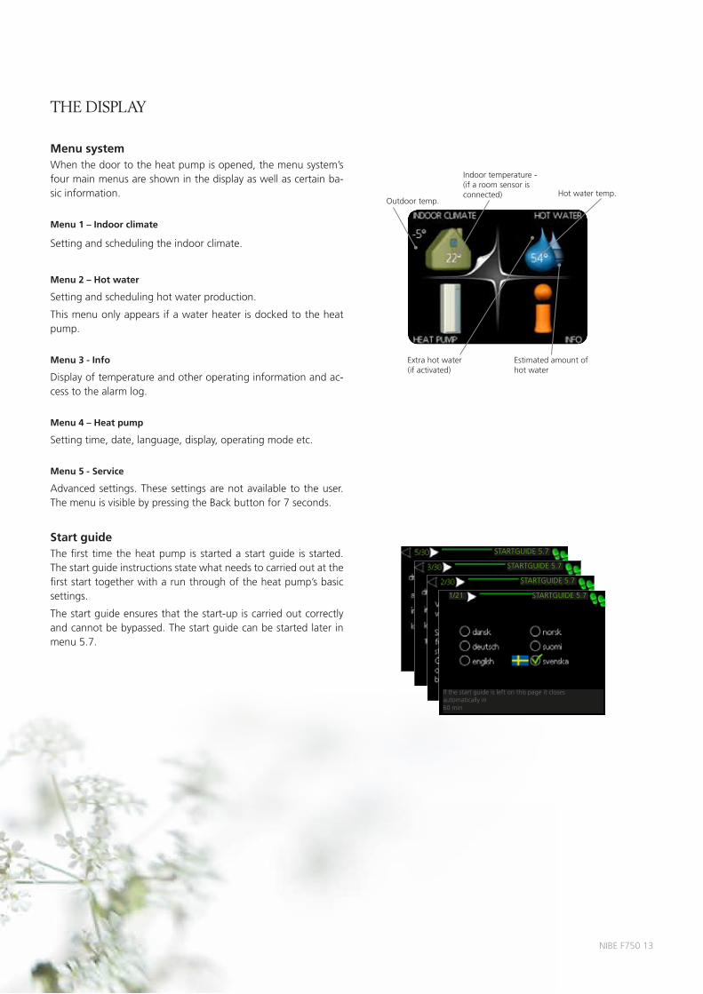
Menu system When the door to the heat pump is opened, the menu system’s four main menus are shown in the display as well as certain ba-sic information.
Menu 1 – Indoor climate
setting and scheduling the indoor climate.
Menu 2 – Hot water
setting and scheduling hot water production.
this menu only appears if a water heater is docked to the heat pump.
Menu 3 - Info
Display of temperature and other operating information and ac-cess to the alarm log.
Menu 4 – Heat pump
setting time, date, language, display, operating mode etc.
Menu 5 - Service
advanced settings. these settings are not available to the user. the menu is visible by pressing the Back button for 7 seconds.
Start guidethe first time the heat pump is started a start guide is started. the start guide instructions state what needs to carried out at the first start together with a run through of the heat pump’s basic settings.
the start guide ensures that the start-up is carried out correctly and cannot be bypassed. the start guide can be started later in menu 5.7.
Indoor temperature - (if a room sensor is connected)
Outdoor temp.hot water temp.
Extra hot water (if activated)
Estimated amount of hot water
startGuIDE 5.7
startGuIDE 5.7
startGuIDE 5.7
startGuIDE 5.7
If the start guide is left on this page it closes automatically in 60 min
1/21

14 NIBE F750
teChniCal speCifiCations
height excl. inverter box, incl. feet mm 2100-2125
required ceiling height mm 2270
Width mm 600
Depth mm 610
Weight kg 235
Volume total litres 215
Volume boiler section (of which buffer vessel) litres 35 (25)
Volume, hot water heater litres 180
Volume buffer vessel litres 25
Capacity hot water 40 °C litres 250
Output data according to EN 14,511 stainless steel
airflow l/s 30 40 50 60 70
pheat 20/45 kW 1.153 1.241 1.304 1.354 1.371
CO pheat 20/45 3.18 3.31 3.46 3.53 3.47
rated voltage V 400 V 3N ~ pE 50 hz
max operating current a 16.1
Fuse a 16
specified output, compressor kW 1.5-6.0
specified output, compressor kW 0.4-2.8
Output immersion heater kW 0.5-6.5
Drive output heating medium pump 2 (Gp6) W 5-45
Driving power exhaust air fan W 25-140
max supply temperature °C 70 (factory setting 60)
Enclosure class Ip 21
max pressure in hot water heater mpa (bar) 1.0/10
max pressure in boiler section mpa (bar) 0.25/2.5
Cut-out value pressostat hp mpa (bar) 2.9/29
Cut-out value pressostat Lp mpa (bar) 0.05/0.5
refrigerant (r407C) kg 0.74
Connection heating medium male Ø mm 22
Connection cold water ext Ø mm 22
Connection hot water ext Ø mm 22
Connection ventilation Ø mm 125
sound power level* dB(a) 40-55
sound level in the boiler house** dB(a) 36-51
part No. 066 061
Outdoor sensor Indoor sensor Vent hose (lenght 1 m)
the kit of supplied items is placed on top of the product.
* a-weighted sound power level (Lwa). the value varies with the speed of the compressor and selected fan curve.** a-weighted sound pressure level (Lpa). the value can vary with the room’s damping capacity. these values apply with a damping of 4 dB.
IP 21
LEK
supplied Components

NIBE F750 15
aCCessories
NIBE Top cabinettop cabinet for room height 2400, 2500, 2550-2800 mm.height: 2400 mmpart no. 089 756height: 2500 mmpart no. 089 757height: 2550-2800 mmpart no. 089 758
LEK
LEK
NIBE VPB 200 Accumulator tankExtra water heater without immersion heater. placed to the left of NIBE F750 for easy installation.VpB 200 Cu part no. 088 515 VpB 200 E part no. 088 517VpB 200 r part no. 088 518
LEK
NIBE SMS 40Communication moduleNIBE sms 40 enables operation to be controlled and monitored, via the Gsm module, using a mobile phone via sms messages. part no. 067 073
LEK
NIBE ECS 40/ ECS 41Extra shunt groupthis accessory is used when NIBE F750 is installed in houses with two or more different climate systems that require different supply temperatures, for exam-ple, in cases where the house has both a radiator system and an underfloor heating system.ECs 40 part no. 067 061 ECs 41 part no. 067 099
LE
K
GR
UN
DFO
STyp
eU
PS
25
- 6
01
30
P/N
:59
52
64
47
23
0V
-
HE
JSA
N
PC
;00
17
NIB
DK
50
Hz
IP
44
TF
1
10
Cla
ss
HM
ax. 1
0b
ar
2.5
uF
45
0.2
06
50
.30
90
0.4
0
1m(A
)P,
(W)
LEK
LEK
NIBE DEW 40Docking kit water heaterFor extra water heater NIBE VpB 200.part no. 067 102
NIBE SAM 40Supply air moduleNIBE sam 40 is a supply air module specially developed for houses with supply and exhaust air systems.part no. 067 147
LEK
NIBE RMU 40Room unitNIBE rmu 40 means that control and monitoring of the operation can be carried out in a different part of the accommodation to where NIBE F750 is located.part no. 067 064
LEK

this brochure is a publication from NIBE. all product illustrations, facts and specifications are based on current information at the time of the publication’s approval. NIBE makes reservations for any factual or printing errors in this brochure. printed by: am-tryck & reklam. photos: www.benfoto.se. ©NIBE 2011.
NIBE is IsO-certified: ss-EN IsO 9001:2000ss-EN IsO 14001:2004
6393
98 t
echn
ical
pBD
GB
NIB
E F7
50 1
149-
2
MILJÖMÄRKT
307–005
NIBE Energy systems aBBox 14285 21 markarydsWEDENtel. +46 433 - 73 000www.nibe.eu