Embed Size (px)
Citation preview
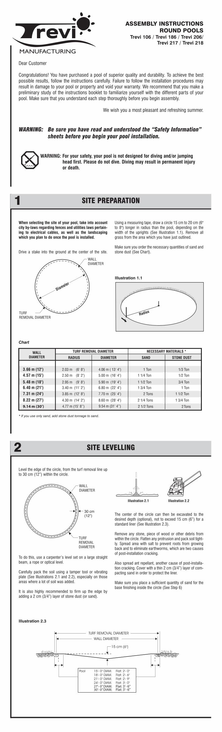
When selecting the site of your pool, take into accountcity by-laws regarding fences and utilities laws pertain-ing to electrical cables, as well as the landscapingwhich you plan to do once the pool is installed.
Drive a stake into the ground at the center of the site.
Using a measuring tape, draw a circle 15 cm to 20 cm (6"to 8") longer in radius than the pool, depending on thewidth of the uprights (See Illustration 1.1). Remove allgrass from the area which you have just outlined.
Make sure you order the necessary quantities of sand andstone dust (See Chart).
Dear Customer
Congratulations! You have purchased a pool of superior quality and durability. To achieve the bestpossible results, follow the instructions carefully. Failure to follow the installation procedures mayresult in damage to your pool or property and void your warranty. We recommend that you make apreliminary study of the instructions booklet to familiarize yourself with the different parts of yourpool. Make sure that you understand each step thoroughly before you begin assembly.
We wish you a most pleasant and refreshing summer.
WARNING: Be sure you have read and understood the “Safety Information” sheets before you begin your pool installation.
WARNING: For your safety, your pool is not designed for diving and/or jumping head first. Please do not dive. Diving may result in permanent injury or death.
SITE PREPARATION1
SITE LEVELLING2
ASSEMBLY INSTRUCTIONSROUND POOLS
Trevi 106 / Trevi 186 / Trevi 206/Trevi 217 / Trevi 218
9.14 m (30’) 4.77 m (15’ 8’’) 9.54 m (31’ 4’’)
* If you use only sand, add stone dust tonnage to sand.
Chart
Illustration 1.1
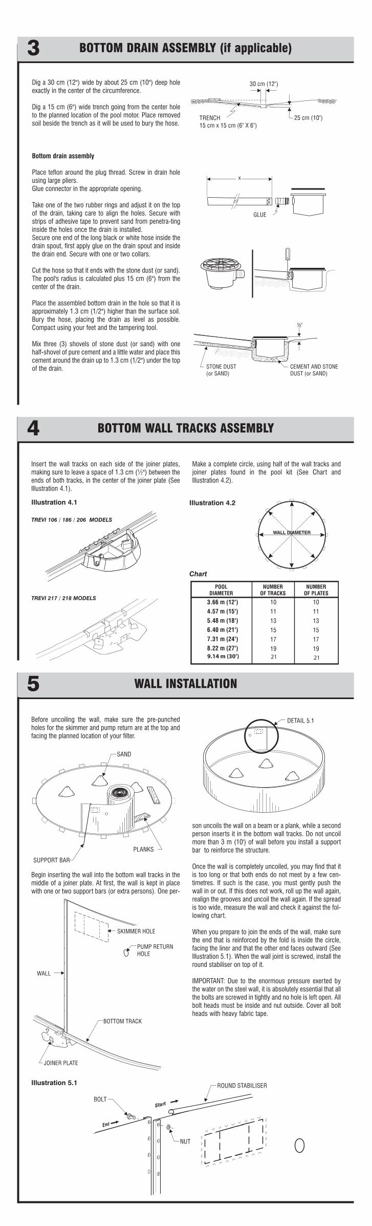
Level the edge of the circle, from the turf removal line upto 30 cm (12”) within the circle.
To do this, use a carpenter’s level set on a large straightbeam, a rope or optical level.
Carefully pack the soil using a tamper tool or vibratingplate (See Illustrations 2.1 and 2.2), especially on thoseareas where a lot of soil was added.
It is also highly recommended to firm up the edge byadding a 2 cm (3/4”) layer of stone dust (or sand).
The center of the circle can then be excavated to thedesired depth (optional), not to exceed 15 cm (6”) for astandard liner (See Illustration 2.3).
Remove any stone, piece of wood or other debris fromwithin the circle. Flatten any protrusion and pack soil tight-ly. Spread area with salt to prevent roots from growingback and to eliminate earthworms, which are two causesof post-installation cracking.
Also spread ant repellant, another cause of post-installa-tion cracking. Cover with a thin 2 cm (3/4”) layer of com-pacting sand in order to protect the liner.
Make sure you place a sufficient quantity of sand for thebase finishing inside the circle (See Step 6)
27’- 0’’ DIAM. Flat: 3’- 6’’30’- 0’’ DIAM. Flat: 3’- 6’’
Illustration 2.3
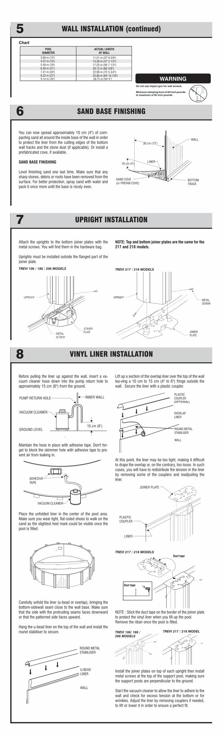
Insert the wall tracks on each side of the joiner plates,making sure to leave a space of 1.3 cm (½") between theends of both tracks, in the center of the joiner plate (SeeIllustration 4.1).
Make a complete circle, using half of the wall tracks andjoiner plates found in the pool kit (See Chart andIllustration 4.2).
BOTTOM WALL TRACKS ASSEMBLY4
Before uncoiling the wall, make sure the pre-punchedholes for the skimmer and pump return are at the top andfacing the planned location of your filter.
Begin inserting the wall into the bottom wall tracks in themiddle of a joiner plate. At first, the wall is kept in placewith one or two support bars (or extra persons). One per-
son uncoils the wall on a beam or a plank, while a secondperson inserts it in the bottom wall tracks. Do not uncoilmore than 3 m (10') of wall before you install a supportbar to reinforce the structure.
Once the wall is completely uncoiled, you may find that itis too long or that both ends do not meet by a few cen-timetres. If such is the case, you must gently push thewall in or out. If this does not work, roll up the wall again,realign the grooves and uncoil the wall again. If the spreadis too wide, measure the wall and check it against the fol-lowing chart.
When you prepare to join the ends of the wall, make surethe end that is reinforced by the fold is inside the circle,facing the liner and that the other end faces outward (SeeIllustration 5.1). When the wall joint is screwed, install theround stabiliser on top of it.
IMPORTANT: Due to the enormous pressure exerted bythe water on the steel wall, it is absolutely essential that allthe bolts are screwed in tightly and no hole is left open. Allbolt heads must be inside and nut outside. Cover all boltheads with heavy fabric tape.
WALL INSTALLATION5
Illustration 4.1 Illustration 4.2
9.14 m (30’) 21 21
Chart
Illustration 5.1
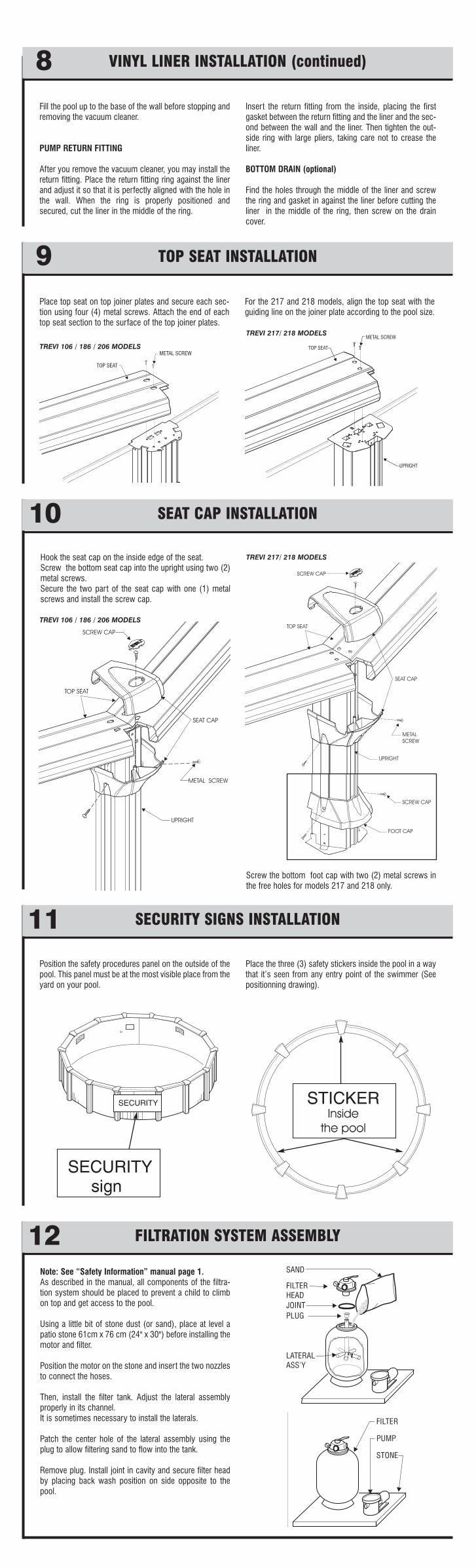
Dig a 30 cm (12") wide by about 25 cm (10") deep holeexactly in the center of the circumference.
Dig a 15 cm (6") wide trench going from the center holeto the planned location of the pool motor. Place removedsoil beside the trench as it will be used to bury the hose.
Bottom drain assembly
Place teflon around the plug thread. Screw in drain holeusing large pliers.Glue connector in the appropriate opening.
Take one of the two rubber rings and adjust it on the topof the drain, taking care to align the holes. Secure withstrips of adhesive tape to prevent sand from penetra-tinginside the holes once the drain is installed.Secure one end of the long black or white hose inside thedrain spout, first apply glue on the drain spout and insidethe drain end. Secure with one or two collars.
Cut the hose so that it ends with the stone dust (or sand).The pool's radius is calculated plus 15 cm (6") from thecenter of the drain.
Place the assembled bottom drain in the hole so that it isapproximately 1.3 cm (1/2") higher than the surface soil.Bury the hose, placing the drain as level as possible.Compact using your feet and the tampering tool.
Mix three (3) shovels of stone dust (or sand) with onehalf-shovel of pure cement and a little water and place thiscement around the drain up to 1.3 cm (1/2") under the topof the drain.
BOTTOM DRAIN ASSEMBLY (if applicable)3
TREVI 106 / 186 / 206 MODELS
TREVI 217 / 218 MODELS
Before pulling the liner up against the wall, insert a va-cuum cleaner hose down into the pump return hole toapproximately 15 cm (6") from the ground.
Maintain the hose in place with adhesive tape. Don't for-get to block the skimmer hole with adhesive tape to pre-vent air from leaking in.
Place the unfolded liner in the center of the pool area.Make sure you wear light, flat-soled shoes to walk on thesand as the slightest heel mark could be visible once thepool is filled.
Carefully unfold the liner (u-bead or overlap), bringing thebottom-sidewall seam close to the wall base. Make surethat the side with the protruding seams faces downwardor that the patterned side faces upward.
Hang the u-bead liner on the top of the wall and install theround stabiliser to secure.
Lift up a section of the overlap liner over the top of the walllea-ving a 10 cm to 15 cm (4" to 6") fringe outside thewall. Secure the liner with a plastic coupler.
At this point, the liner may be too tight, making it difficultto drape the overlap or, on the contrary, too loose. In suchcases, you will have to redistribute the tension in the linerby removing some of the couplers and readjusting theliner.
NOTE : Stick the duct tape on the border of the joiner plateto protect the vinyl liner when you fill up the pool.Remove the riban once the pool is filled.
Install the joiner plates on top of each upright then installmetal screws at the top of the support post, making surethe support posts are perpendicular to the ground.
Start the vacuum cleaner to allow the liner to adhere to thewall and check for excess tension at the bottom or forwrinkles. Adjust the liner by removing couplers if needed,to lift or lower it in order to ensure a perfect fit.
VINYL LINER INSTALLATION8
TREVI 106/ 186 / 206 MODELS
TREVI 217 / 218 MODEL
You can now spread approximately 10 cm (4") of com-pacting sand all around the inside base of the wall in orderto protect the liner from the cutting edges of the bottomwall tracks and the stone dust (if applicable). Or install aprefabricated cove, if available.
SAND BASE FINISHING
Level finishing sand one last time. Make sure that anysharp stones, debris or roots have been removed from thesurface. For better protection, spray sand with water andpack it once more until the base is nicely even.
SAND BASE FINISHING6
WALL INSTALLATION (continued)5
Attach the uprights to the bottom joiner plates with themetal screws. You will find them in the hardware bag.
Uprights must be installed outside the flanged part of thejoiner plate.
NOTE: Top and bottom joiner plates are the same for the217 and 218 models.
UPRIGHT INSTALLATION7
TREVI 106 / 186 / 206 MODELS TREVI 217 / 218 MODELS
9.14 m (30’) 28,75 m (94’ 4’’)
Chart
TREVI 217 / 218 MODELS
(OPTIONAL)
Do not use impact gun for wall screws.
Minimum clamping force of 60 inch pounds to maximum of 85 inch pounds
WARNINGWARNING
Note: See “Safety Information” manual page 1.As described in the manual, all components of the filtra-tion system should be placed to prevent a child to climbon top and get access to the pool.
Using a little bit of stone dust (or sand), place at level apatio stone 61cm x 76 cm (24" x 30") before installing themotor and filter.
Position the motor on the stone and insert the two nozzlesto connect the hoses.
Then, install the filter tank. Adjust the lateral assemblyproperly in its channel.It is sometimes necessary to install the laterals.
Patch the center hole of the lateral assembly using theplug to allow filtering sand to flow into the tank.
Remove plug. Install joint in cavity and secure filter headby placing back wash position on side opposite to thepool.
FILTRATION SYSTEM ASSEMBLY12
Hook the seat cap on the inside edge of the seat. Screw the bottom seat cap into the upright using two (2)metal screws. Secure the two part of the seat cap with one (1) metalscrews and install the screw cap.
SEAT CAP INSTALLATION10
Position the safety procedures panel on the outside of thepool. This panel must be at the most visible place from theyard on your pool.
Place the three (3) safety stickers inside the pool in a waythat it’s seen from any entry point of the swimmer (Seepositionning drawing).
SECURITY SIGNS INSTALLATION11
Place top seat on top joiner plates and secure each sec-tion using four (4) metal screws. Attach the end of eachtop seat section to the surface of the top joiner plates.
For the 217 and 218 models, align the top seat with theguiding line on the joiner plate according to the pool size.
Fill the pool up to the base of the wall before stopping andremoving the vacuum cleaner.
PUMP RETURN FITTING
After you remove the vacuum cleaner, you may install thereturn fitting. Place the return fitting ring against the linerand adjust it so that it is perfectly aligned with the hole inthe wall. When the ring is properly positioned andsecured, cut the liner in the middle of the ring.
Insert the return fitting from the inside, placing the firstgasket between the return fitting and the liner and the sec-ond between the wall and the liner. Then tighten the out-side ring with large pliers, taking care not to crease theliner.
BOTTOM DRAIN (optional)
Find the holes through the middle of the liner and screwthe ring and gasket in against the liner before cutting theliner in the middle of the ring, then screw on the draincover.
TOP SEAT INSTALLATION9
VINYL LINER INSTALLATION (continued)8
TREVI 106 / 186 / 206 MODELS
TREVI 217/ 218 MODELS
TREVI 217/ 218 MODELS
TREVI 106 / 186 / 206 MODELS
Screw the bottom foot cap with two (2) metal screws inthe free holes for models 217 and 218 only.
PARTS LIST14
TREVI 106 / 186 / 206 MODELS
TREVI 217 / 218 MODELS
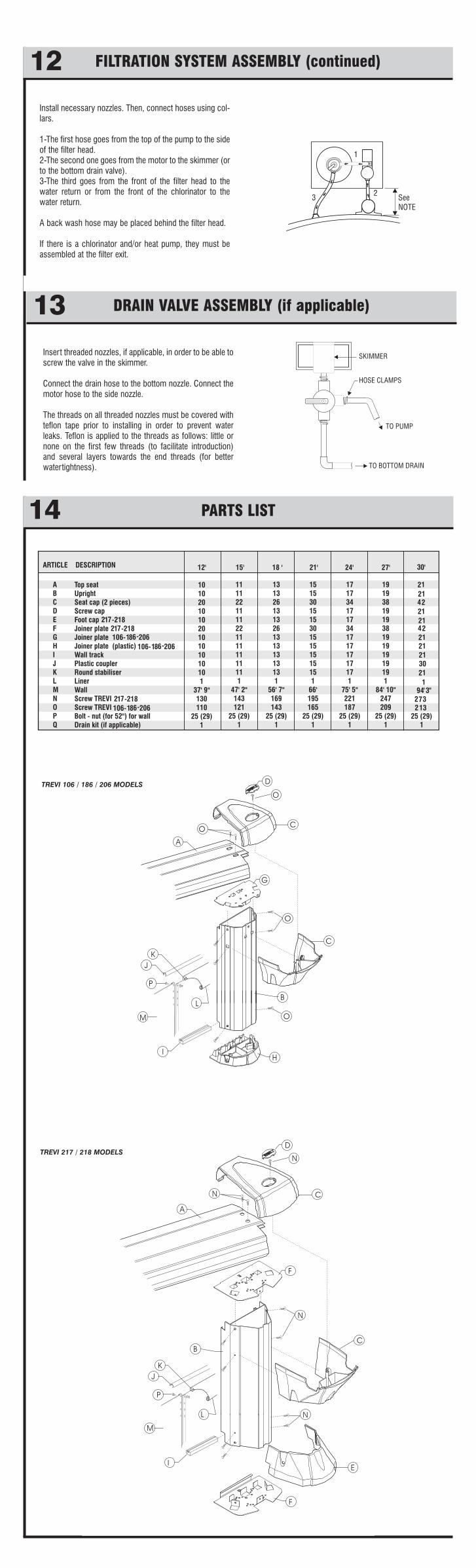
Install necessary nozzles. Then, connect hoses using col-lars.
1-The first hose goes from the top of the pump to the sideof the filter head. 2-The second one goes from the motor to the skimmer (orto the bottom drain valve).3-The third goes from the front of the filter head to thewater return or from the front of the chlorinator to thewater return.
A back wash hose may be placed behind the filter head.
If there is a chlorinator and/or heat pump, they must beassembled at the filter exit.
FILTRATION SYSTEM ASSEMBLY (continued)12
Insert threaded nozzles, if applicable, in order to be able toscrew the valve in the skimmer.
Connect the drain hose to the bottom nozzle. Connect themotor hose to the side nozzle.
The threads on all threaded nozzles must be covered withteflon tape prior to installing in order to prevent waterleaks. Teflon is applied to the threads as follows: little ornone on the first few threads (to facilitate introduction)and several layers towards the end threads (for betterwatertightness).
DRAIN VALVE ASSEMBLY (if applicable)13


![PHOTOGRAPHS OF NIAGARA, MARINETTE … of Niagara... · PHOTOGRAPHS OF NIAGARA, MARINETTE COUNTY, WISCONSIN [Compiled and Captioned by William John Cummings] 3 View of Niagara, Wisconsin,](https://img.pdfslide.us/doc/110x75/5b993acd09d3f207308b54bc/photographs-of-niagara-marinette-of-niagara-photographs-of-niagara-marinette.jpg)