Embed Size (px)
Citation preview

TEC
HN
ICA
L IN
FOR
MAT
ION
1TECHNICAL INFORMATION
TECHNICAL INFORMATION
2 Cutting-Off & Grinding Wheels• Technical Information• Troubleshooting• Safety Advice
10 Coated Abrasives• Technical Information• Safety Advice
21 Beartex• Product Selection -
by Machine• Product Selection -
by Application
31 Bonded Abrasives• Technical Information• Troubleshooting• Safety Advice
44 Super Abrasives• Technical Information• Troubleshooting
49 Diamond Blades• Technical Information• Troubleshooting• Safety Advice
2 TECHNICAL INFORMATIONTEC
HN
ICA
L IN
FOR
MAT
ION
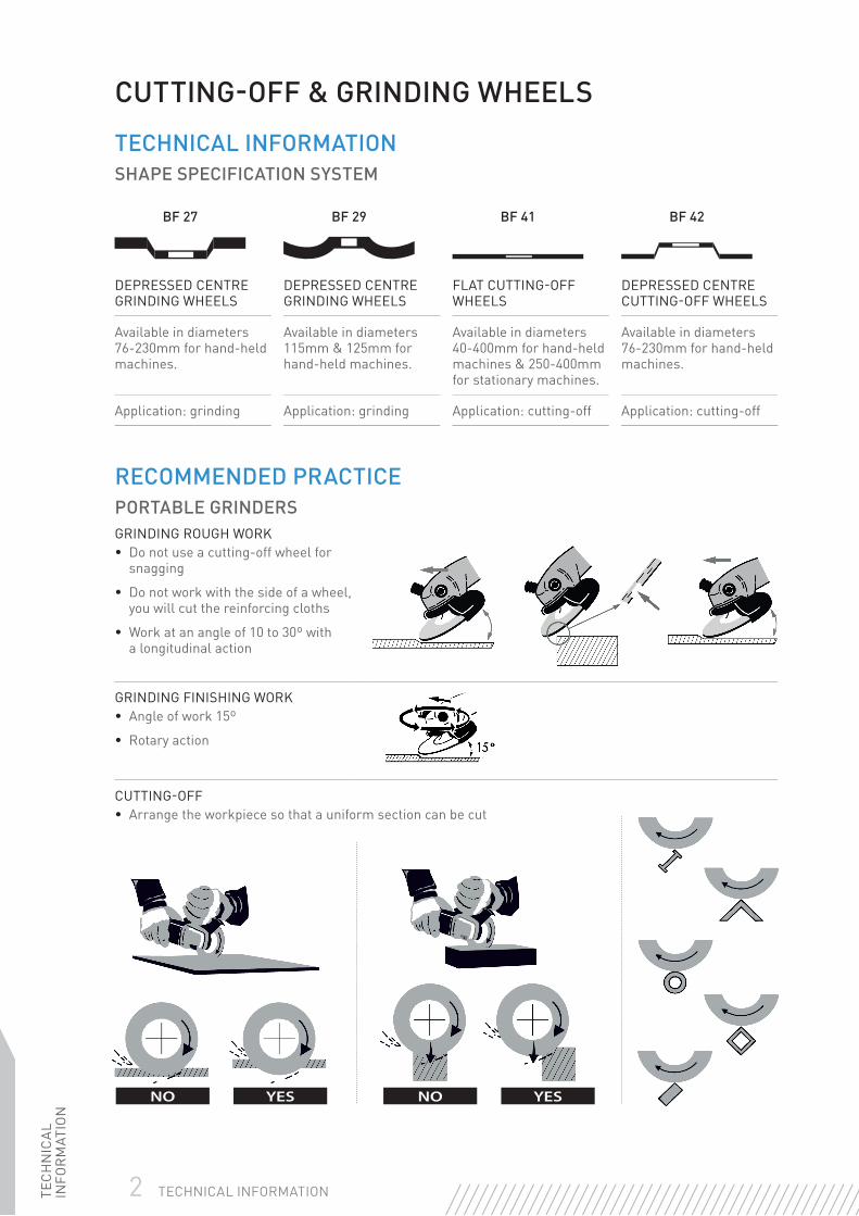
RECOMMENDED PRACTICEPORTABLE GRINDERSGRINDING ROUGH WORK• Do not use a cutting-off wheel for
snagging
• Do not work with the side of a wheel, you will cut the reinforcing cloths
• Work at an angle of 10 to 30º with a longitudinal action
GRINDING FINISHING WORK• Angle of work 15º
• Rotary action
CUTTING-OFF• Arrange the workpiece so that a uniform section can be cut
YESNOYESNO
CUTTING-OFF & GRINDING WHEELS
TECHNICAL INFORMATIONSHAPE SPECIFICATION SYSTEM
BF 27 BF 29 BF 41 BF 42
DEPRESSED CENTRE GRINDING WHEELS
DEPRESSED CENTRE GRINDING WHEELS
FLAT CUTTING-OFF WHEELS
DEPRESSED CENTRE CUTTING-OFF WHEELS
Available in diameters 76-230mm for hand-held machines.
Available in diameters 115mm & 125mm for hand-held machines.
Available in diameters 40-400mm for hand-held machines & 250-400mm for stationary machines.
Available in diameters 76-230mm for hand-held machines.
Application: grinding Application: grinding Application: cutting-off Application: cutting-off
TEC
HN
ICA
L IN
FOR
MAT
ION
3TECHNICAL INFORMATION
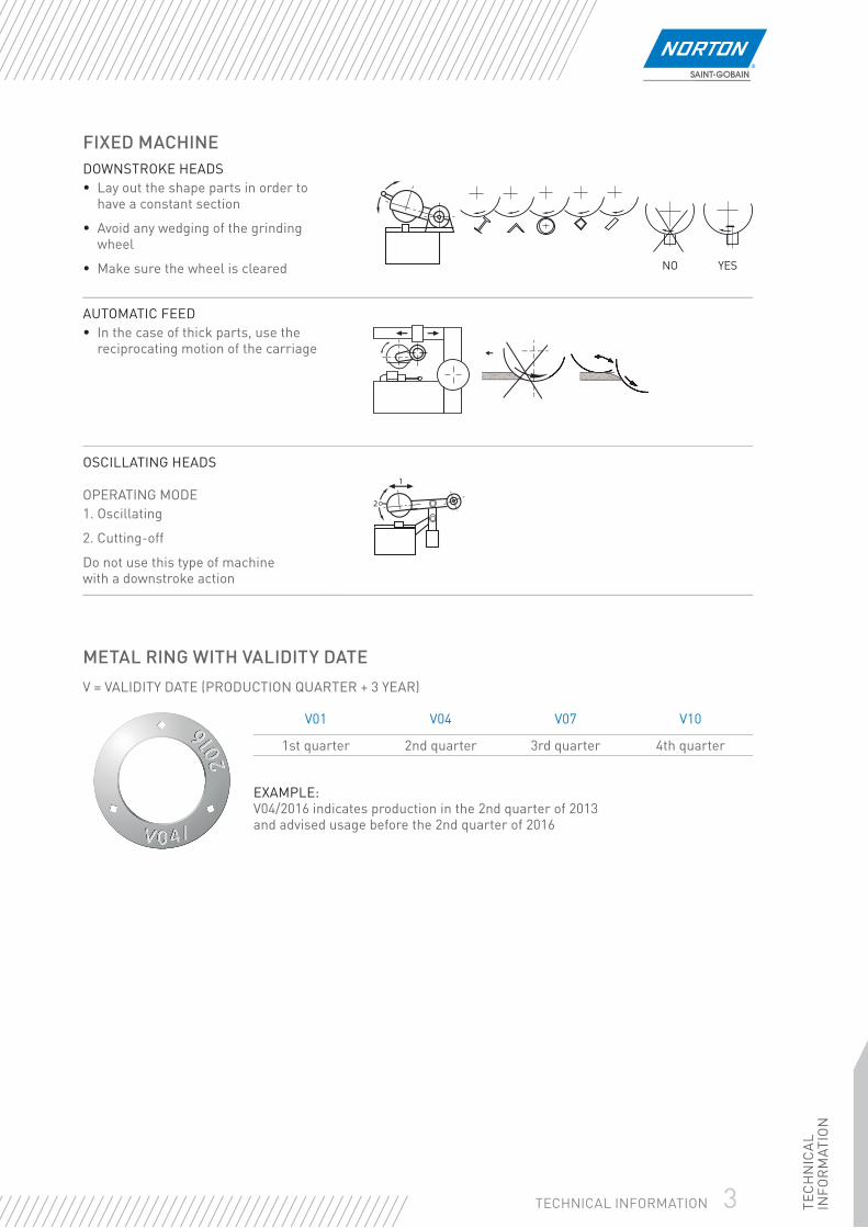
FIXED MACHINEDOWNSTROKE HEADS• Lay out the shape parts in order to
have a constant section
• Avoid any wedging of the grinding wheel
• Make sure the wheel is cleared
AUTOMATIC FEED• In the case of thick parts, use the
reciprocating motion of the carriage
OSCILLATING HEADS
OPERATING MODE1. Oscillating
2. Cutting-off
Do not use this type of machine with a downstroke action
NO YES
METAL RING WITH VALIDITY DATEV = VALIDITY DATE (PRODUCTION QUARTER + 3 YEAR)
V01 V04 V07 V10
1st quarter 2nd quarter 3rd quarter 4th quarter
EXAMPLE:V04/2016 indicates production in the 2nd quarter of 2013 and advised usage before the 2nd quarter of 2016

4 TECHNICAL INFORMATIONTEC
HN
ICA
L IN
FOR
MAT
ION
PERSONAL PROTECTIONSafety goggles, ear defenders, safety gloves, dust masks and, if conditions are severe, additional face protection. Leather aprons and safety shoes must be worn.
MouthProtection
WearGloves
EyeProtection
EarProtection
ReadInstructions
Damaged Wheel –
Do not use
GENERAL PRECAUTIONS
Safety instructions provided by the machine manufacturers must be followed. Where fi tted, all guards, covers and hoods must be in place on the machine during grinding, and should not be modifi ed in any way. Abrasives should not be used near infl ammable material or in an environment where there is a risk of explosion.
Sparks should be directed away from the face and body, if possible towards the fl oor. Dust extraction equipment must be used whenever it is available. The instructions for use given by the abrasive manufacturer must be followed e.g. ‘Not to be used without a support’, or ‘Not to be used for wet grinding’. The workpiece must be fi rmly fi xed before grinding starts. Check all abrasives visually before use and make certain that the product is suitable for the application. No modifi cations should be made to abrasive products after delivery.
When using a portable grinder always switch it off and allow the spindle to stop completely before putting the tool down. Wet grinding should only be carried out on machines designed for this purpose and with abrasives designated as suitable for this type of operation.
Dry Wet
TEC
HN
ICA
L IN
FOR
MAT
ION
5TECHNICAL INFORMATION
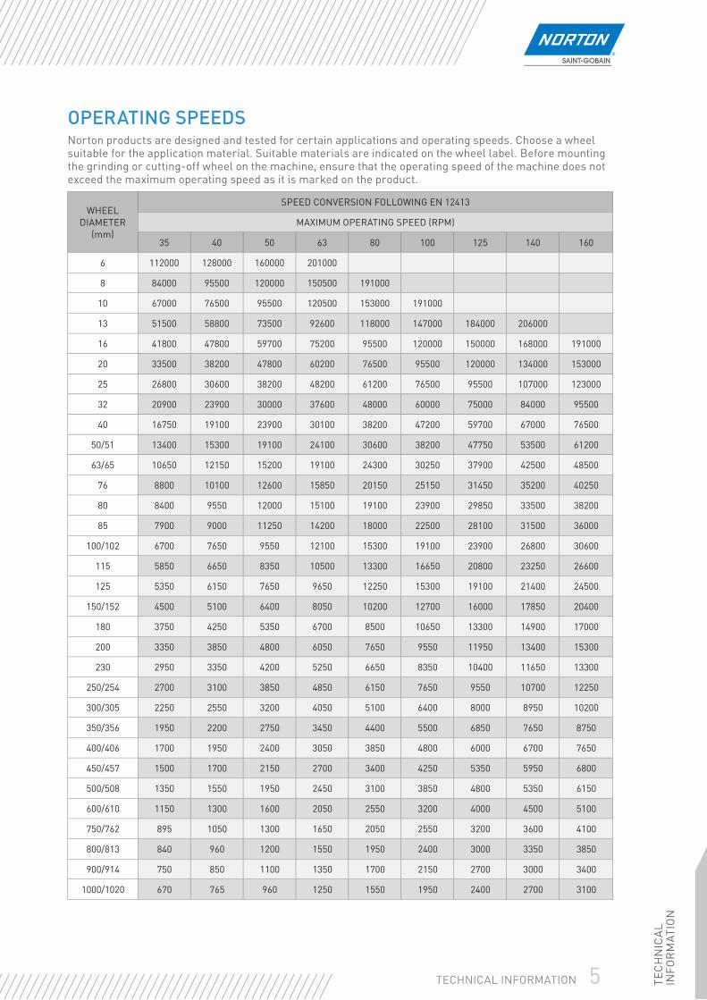
OPERATING SPEEDSNorton products are designed and tested for certain applications and operating speeds. Choose a wheel suitable for the application material. Suitable materials are indicated on the wheel label. Before mounting the grinding or cutting-off wheel on the machine, ensure that the operating speed of the machine does not exceed the maximum operating speed as it is marked on the product.
WHEEL DIAMETER
(mm)
SPEED CONVERSION FOLLOWING EN 12413
MAXIMUM OPERATING SPEED (RPM)
35 40 50 63 80 100 125 140 160
6 112000 128000 160000 201000
8 84000 95500 120000 150500 191000
10 67000 76500 95500 120500 153000 191000
13 51500 58800 73500 92600 118000 147000 184000 206000
16 41800 47800 59700 75200 95500 120000 150000 168000 191000
20 33500 38200 47800 60200 76500 95500 120000 134000 153000
25 26800 30600 38200 48200 61200 76500 95500 107000 123000
32 20900 23900 30000 37600 48000 60000 75000 84000 95500
40 16750 19100 23900 30100 38200 47200 59700 67000 76500
50/51 13400 15300 19100 24100 30600 38200 47750 53500 61200
63/65 10650 12150 15200 19100 24300 30250 37900 42500 48500
76 8800 10100 12600 15850 20150 25150 31450 35200 40250
80 8400 9550 12000 15100 19100 23900 29850 33500 38200
85 7900 9000 11250 14200 18000 22500 28100 31500 36000
100/102 6700 7650 9550 12100 15300 19100 23900 26800 30600
115 5850 6650 8350 10500 13300 16650 20800 23250 26600
125 5350 6150 7650 9650 12250 15300 19100 21400 24500
150/152 4500 5100 6400 8050 10200 12700 16000 17850 20400
180 3750 4250 5350 6700 8500 10650 13300 14900 17000
200 3350 3850 4800 6050 7650 9550 11950 13400 15300
230 2950 3350 4200 5250 6650 8350 10400 11650 13300
250/254 2700 3100 3850 4850 6150 7650 9550 10700 12250
300/305 2250 2550 3200 4050 5100 6400 8000 8950 10200
350/356 1950 2200 2750 3450 4400 5500 6850 7650 8750
400/406 1700 1950 2400 3050 3850 4800 6000 6700 7650
450/457 1500 1700 2150 2700 3400 4250 5350 5950 6800
500/508 1350 1550 1950 2450 3100 3850 4800 5350 6150
600/610 1150 1300 1600 2050 2550 3200 4000 4500 5100
750/762 895 1050 1300 1650 2050 2550 3200 3600 4100
800/813 840 960 1200 1550 1950 2400 3000 3350 3850
900/914 750 850 1100 1350 1700 2150 2700 3000 3400
1000/1020 670 765 960 1250 1550 1950 2400 2700 3100

6 TECHNICAL INFORMATIONTEC
HN
ICA
L IN
FOR
MAT
ION
TROUBLESHOOTINGCUTTING-OFF WHEELS
WHEEL DOES NOT CUT
Cause In case of blue cutting: wheel too hard or too thick
Solution Use softer or Norton Thin Cut wheels, check peripheral speed
Cause Peripheral speed too low
Solution Increase rpm up to max. (80m/sec)
EXCESSIVE WEAR
Cause In case of white cutting edge: wheel too soft
Solution Use harder wheel
Cause Operating speed too low
Solution Increase rpm up to max (80m/sec)
Cause Decrease of rpm during cutting
Solution Use machine with more power, reduce pressure on the machine
CRUMBLED WHEEL EDGE
Cause Cutting-off wheel used for grinding operations
Solution Use a grinding wheel for grinding operations
Cause Workpiece is moving
Solution Clamp the workpiece properly
Cause Too much side-pressure
Solution Add only the radial pressure to the wheel
ARBOR HOLE OR CENTRE BREAK OUT
Cause Wheel sticks in the workpiece/material
Solution Use more radial pressure & swing the wheel forwards and backwards
Cause Cutting-off wheel used for grinding operations
Solution Use a grinding wheel for grinding operations
Cause Too much side pressure
Solution Add only the radial pressure to the wheel
Cause Different diameter top/bottom fl ange
Solution Use fl anges with the same diameter

TEC
HN
ICA
L IN
FOR
MAT
ION
7TECHNICAL INFORMATION
GRINDING WHEELS
WHEEL DOES NOT CUT
Cause Wheel too hard, wheelglazing
Solution Use softer wheel
Cause Not enough pressure
Solution Increase pressure
Cause Machine power too low
Solution Use machine with more power
Cause Loading & wheelglazing (non-ferrous)
Solution Use Norton Alu wheels which counteract loading & wheelglazing
EXCESSIVE WHEELWEAR
Cause Wheel too soft
Solution Use harder wheel
Cause Too much pressure
Solution Reduce pressure, let the wheel do the grinding
Cause Decrease of peripheral speed
Solution Use machine with more power, reduce pressure on the machine
Cause Too low peripheral speed
Solution Max. 80m/sec is optimum speed
CRUMBLED WHEEL EDGE
Cause Grinding angle too fl at
Solution Change angle to 30 - 40°
Cause Workpiece is moving
Solution Clamp the workpiece properly
Cause Too much pressure
Solution Reduce pressure, let the wheel do the grinding
CRACKS ON THE BOTTOM OF THE WHEEL
Cause Contact area too large
Solution Reduce contact area
Cause Too much pressure
Solution Reduce pressure, let the wheel do the grinding
UNBALANCE
Cause Dirty fl anges
Solution Clean fl anges
Cause Wheel mounting insecure
Solution Tighten fl anges
Cause Flanges with different diameter
Solution Replace fl anges
8 TECHNICAL INFORMATIONTEC
HN
ICA
L IN
FOR
MAT
ION
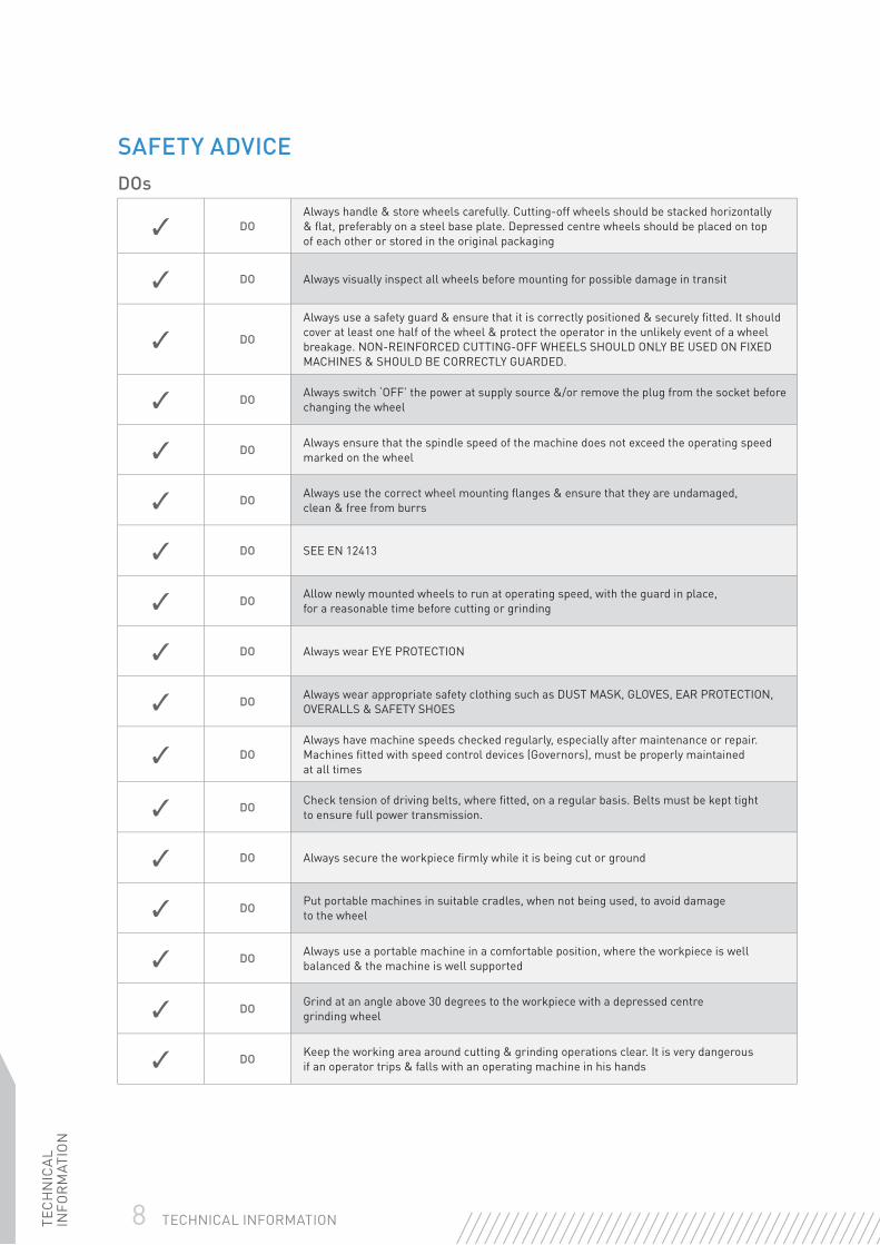
SAFETY ADVICEDOs
✓ DOAlways handle & store wheels carefully. Cutting-off wheels should be stacked horizontally & fl at, preferably on a steel base plate. Depressed centre wheels should be placed on top of each other or stored in the original packaging
✓ DO Always visually inspect all wheels before mounting for possible damage in transit
✓ DO
Always use a safety guard & ensure that it is correctly positioned & securely fi tted. It should cover at least one half of the wheel & protect the operator in the unlikely event of a wheel breakage. NON-REINFORCED CUTTING-OFF WHEELS SHOULD ONLY BE USED ON FIXED MACHINES & SHOULD BE CORRECTLY GUARDED.
✓ DO Always switch ‘OFF’ the power at supply source &/or remove the plug from the socket before changing the wheel
✓ DO Always ensure that the spindle speed of the machine does not exceed the operating speed marked on the wheel
✓ DO Always use the correct wheel mounting fl anges & ensure that they are undamaged, clean & free from burrs
✓ DO SEE EN 12413
✓ DO Allow newly mounted wheels to run at operating speed, with the guard in place, for a reasonable time before cutting or grinding
✓ DO Always wear EYE PROTECTION
✓ DO Always wear appropriate safety clothing such as DUST MASK, GLOVES, EAR PROTECTION, OVERALLS & SAFETY SHOES
✓ DOAlways have machine speeds checked regularly, especially after maintenance or repair. Machines fi tted with speed control devices (Governors), must be properly maintained at all times
✓ DO Check tension of driving belts, where fi tted, on a regular basis. Belts must be kept tight to ensure full power transmission.
✓ DO Always secure the workpiece fi rmly while it is being cut or ground
✓ DO Put portable machines in suitable cradles, when not being used, to avoid damage to the wheel
✓ DO Always use a portable machine in a comfortable position, where the workpiece is well balanced & the machine is well supported
✓ DO Grind at an angle above 30 degrees to the workpiece with a depressed centre grinding wheel
✓ DO Keep the working area around cutting & grinding operations clear. It is very dangerous if an operator trips & falls with an operating machine in his hands
TEC
HN
ICA
L IN
FOR
MAT
ION
9TECHNICAL INFORMATION
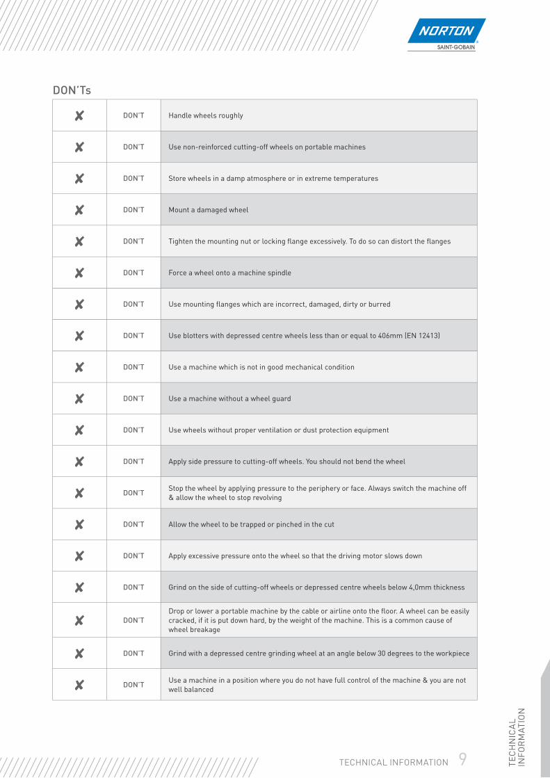
DON’Ts
✘ DON’T Handle wheels roughly
✘ DON’T Use non-reinforced cutting-off wheels on portable machines
✘ DON’T Store wheels in a damp atmosphere or in extreme temperatures
✘ DON’T Mount a damaged wheel
✘ DON’T Tighten the mounting nut or locking fl ange excessively. To do so can distort the fl anges
✘ DON’T Force a wheel onto a machine spindle
✘ DON’T Use mounting fl anges which are incorrect, damaged, dirty or burred
✘ DON’T Use blotters with depressed centre wheels less than or equal to 406mm (EN 12413)
✘ DON’T Use a machine which is not in good mechanical condition
✘ DON’T Use a machine without a wheel guard
✘ DON’T Use wheels without proper ventilation or dust protection equipment
✘ DON’T Apply side pressure to cutting-off wheels. You should not bend the wheel
✘ DON’T Stop the wheel by applying pressure to the periphery or face. Always switch the machine off & allow the wheel to stop revolving
✘ DON’T Allow the wheel to be trapped or pinched in the cut
✘ DON’T Apply excessive pressure onto the wheel so that the driving motor slows down
✘ DON’T Grind on the side of cutting-off wheels or depressed centre wheels below 4,0mm thickness
✘ DON’TDrop or lower a portable machine by the cable or airline onto the fl oor. A wheel can be easily cracked, if it is put down hard, by the weight of the machine. This is a common cause of wheel breakage
✘ DON’T Grind with a depressed centre grinding wheel at an angle below 30 degrees to the workpiece
✘ DON’T Use a machine in a position where you do not have full control of the machine & you are not well balanced
10 TECHNICAL INFORMATIONTEC
HN
ICA
L IN
FOR
MAT
ION
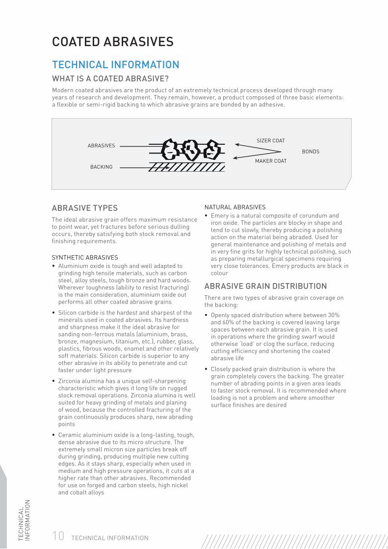
ABRASIVES
BACKING
BONDS
SIZER COAT
MAKER COAT
COATED ABRASIVES
ABRASIVE TYPESThe ideal abrasive grain offers maximum resistance to point wear, yet fractures before serious dulling occurs, thereby satisfying both stock removal and fi nishing requirements.
SYNTHETIC ABRASIVES• Aluminium oxide is tough and well adapted to
grinding high tensile materials, such as carbon steel, alloy steels, tough bronze and hard woods. Wherever toughness (ability to resist fracturing) is the main consideration, aluminium oxide out performs all other coated abrasive grains
• Silicon carbide is the hardest and sharpest of the minerals used in coated abrasives. Its hardness and sharpness make it the ideal abrasive for sanding non-ferrous metals (aluminium, brass, bronze, magnesium, titanium, etc.), rubber, glass, plastics, fi brous woods, enamel and other relatively soft materials. Silicon carbide is superior to any other abrasive in its ability to penetrate and cut faster under light pressure
• Zirconia alumina has a unique self-sharpening characteristic which gives it long life on rugged stock removal operations. Zirconia alumina is well suited for heavy grinding of metals and planing of wood, because the controlled fracturing of the grain continuously produces sharp, new abrading points
• Ceramic aluminium oxide is a long-lasting, tough, dense abrasive due to its micro structure. The extremely small micron size particles break off during grinding, producing multiple new cutting edges. As it stays sharp, especially when used in medium and high pressure operations, it cuts at a higher rate than other abrasives. Recommended for use on forged and carbon steels, high nickel and cobalt alloys
NATURAL ABRASIVES• Emery is a natural composite of corundum and
iron oxide. The particles are blocky in shape and tend to cut slowly, thereby producing a polishing action on the material being abraded. Used for general maintenance and polishing of metals and in very fi ne grits for highly technical polishing, such as preparing metallurgical specimens requiring very close tolerances. Emery products are black in colour
ABRASIVE GRAIN DISTRIBUTION There are two types of abrasive grain coverage on the backing:
• Openly spaced distribution where between 30% and 60% of the backing is covered leaving large spaces between each abrasive grain. It is used in operations where the grinding swarf would otherwise ‘load’ or clog the surface, reducing cutting effi ciency and shortening the coated abrasive life
• Closely packed grain distribution is where the grain completely covers the backing. The greater number of abrading points in a given area leads to faster stock removal. It is recommended where loading is not a problem and where smoother surface fi nishes are desired
TECHNICAL INFORMATIONWHAT IS A COATED ABRASIVE?Modern coated abrasives are the product of an extremely technical process developed through many years of research and development. They remain, however, a product composed of three basic elements: a fl exible or semi-rigid backing to which abrasive grains are bonded by an adhesive.

TEC
HN
ICA
L IN
FOR
MAT
ION
11TECHNICAL INFORMATION
PARTICLE SIZE IN INCHES
PARTICLE SIZE IN MICRON
ALUMINIUM OXIDE, GARNET, SILICON CARBIDE, ZIRCONIA ALUMINA EMERY
GLASS PAPERGRADING SYSTEMS COMP. GRIT
SYMBOLPOLISHING
PAPER CLOTHCAMI FEPA
,0000118 0,3 – – – – – –
,0000197 0,5 – – – – – –
,0000394 1,0 – – – – – –
,0000787 2,0 – – – – – –
,000118 3,0 – – – – – –
,000158 4,0 – – – – – –
,000197 5,0 – – – – – –
,000236 6,0 – – – – – –
,00026 6,5 1200 – – – – –
,00035 9,0 – – – – – –
,00036 9,2 1000 – – – – –
,00047 12,0 – – – – – –
,00048 12,2 800 – – 4/0 – –
,00059 15,0 – – – – – –
,00060 15,3 – P1200 – – – –
,00062 16,0 600 – – 3/0 – –
,00071 18,3 – P1000 – – – –
,00077 19,7 500 – – 2/0 – –
,00079 20,0 – – – – – –
,00085 21,8 – P800 – – – –
,00092 23,6 400 – 10/0 0 – –
,00098 25,0 – – – – – –
,00100 27,75 – P600 – – – –
,00112 28,8 360 – – – – –
,00118 30,0 – – – – – –
,00118 30,2 – P500 – – – –
,00137 35,0 – P400 – – – –
,00140 36,0 320 – 9/0 – – –
,001575 40,0 – – – – – –
,00158 40,5 – P360 – – – –
,00172 44,0 280 – 8/0 1 – –
,00177 45,0 – – – – – –
,00180 46,2 – P320 – – – –
,00197 50,0 – – – – – –
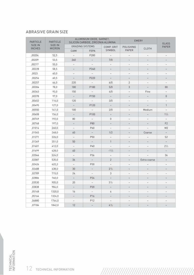
ABRASIVE GRAIN SIZEAfter the crude abrasives have been crushed, the grains are separated (graded) into standard particle sizes using screens carefully made from silk threads of exact size and number per square inch to ensure extreme accuracy. The grit number (mesh number) appearing on the coated abrasive backing represents the number of openings per linear inch in the fi nal screen. Grits 240 and fi ner, called fl ours, are graded by hydraulic separators, air classifi ers and levigating tanks.
The European standard of grit sizes is the FEPA grading system. All FEPA grit sizes are preceded with the letter ‘P’, i.e. P180 etc.
In the USA a different grading system called CAMI is used. This chart provides a comparison between FEPA and CAMI grades and also shows average particle sizes in microns and inches.
Additionally, some products produced for the woodworking and fl oor sanding markets are identifi ed with a ‘grit symbol’. Although use of this symbol is infrequent, the backing of these products contain both the mesh number and the grit symbol.
12 TECHNICAL INFORMATIONTEC
HN
ICA
L IN
FOR
MAT
ION
PARTICLE SIZE IN INCHES
PARTICLE SIZE IN MICRON
ALUMINIUM OXIDE, GARNET, SILICON CARBIDE, ZIRCONIA ALUMINA EMERY
GLASS PAPERGRADING SYSTEMS COMP. GRIT
SYMBOLPOLISHING
PAPER CLOTHCAMI FEPA
,00204 52,5 – P280 – – – –
,00209 53,5 240 – 7/0 – – –
,00217 55,0 – – – – – –
,00228 58,5 – P240 – – – –
,0023 60,0 – – – – – –
,00254 60,5 – P220 – – – –
,00257 66,0 220 – 6/0 2 – –
,00304 78,0 180 P180 5/0 3 – 00
,00363 93,0 150 – 4/0 – Fine –
,00378 97,0 – P150 – – – 0
,00452 116,0 120 – 3/0 – – –
,00495 127,0 – P120 – – – 1
,00550 141,0 100 – 2/0 – Medium –
,00608 156,0 – P100 – – – 11/2
,00749 192,0 80 – 0 – – –
,00768 197,0 – P80 – – – F2
,01014 260,0 – P60 – – – M2
,01045 268,0 60 – 1/2 – Coarse –
,01271 326,0 – P50 – – – S2
,01369 351,0 50 – 1 – – –
,01601 412,0 – P40 – – – 21/2
,01699 428,0 40 – -11/2 – – –
,02044 524,0 – P36 – – – 36
,02087 535,0 36 – 2 – Extra coarse –
,02426 622,2 – P30 – – – –
,02488 638,0 30 – 21/2 – – –
,02789 715,0 24 – 3 – – –
,02886 740,0 – P24 – – – –
,03530 905,0 20 – 31/2 – – –
,03838 984,0 – P20 – – – –
,05148 1320,0 16 – 4 – – –
,05164 1324,0 – P16 – – – –
,06880 1764,0 – P12 – – – –
,07184 1842,0 12 – 41/2 – – –
ABRASIVE GRAIN SIZE

TEC
HN
ICA
L IN
FOR
MAT
ION
13TECHNICAL INFORMATION
NARROW BELTS & WIDE BELTSThe results achieved when sanding with belts depends on several factors including:
• The machine condition & available horsepower
• The belt speed
• The grinding pressure
• The contact wheel
• The choice of the belt in relation to the shape of the part & material type
• The use of coolant (when machine & belt allows)
BELT SPEEDThe speed of the belt has a direct relationship with its cut rate, as well as the amount of heat generated, the surface fi nish achieved, and the stress on abrasive grain. Some abrasives like zirconia alumina and ceramic support much higher stresses because they have a better resistance to uncontrolled fracture. Some materials are more sensitive to heat generation. The chart below gives the recommended speed range according to material.
RECOMMENDED GRINDING BELT SPEED
Heat sensitive materials, plastics, etc.
5-15m/s Stainless steel, high-speed steel & tool steel
20-30m/s
Sintered metals & carbides 8-15m/s Grey cast iron & cast steel 30-40m/s
Titanium & similar alloys 8-15m/s Carbon steel 30-40m/s
Glass, porcelain & special steel 8-15m/s Brass, copper, zinc, bronze & tin 25-35m/s
Heat-resistant plastics 20-30m/s Aluminium & light metal 20-35m/s
Wood 15-30m/s Varnish 10-15m/s
GRINDING PRESSUREThe amount of grinding pressure depends on:
• The force used
• The size of the contact area between the belt & the workpiece
• The backing on which the belt runs (generally a contact wheel)
Higher pressure increases the cut rate and the amount of heat generated increases the stress on the individual abrasive grain (a minimum stress is necessary to achieve a controlled fracture of the abrasive grain), and generally generates a rougher fi nish.

14 TECHNICAL INFORMATIONTEC
HN
ICA
L IN
FOR
MAT
ION
Aggressiveness increases as angle increases
HARD SOFT
Contact surface decreases as lands decrease giving a more aggressive, harder wheel
CONTACT WHEELSMany machines use contact wheels as a backing for belts. Contact wheels are generally covered with rubber, polyurethane, steel, rubber foam, felt, or compressed canvas, and are classifi ed from soft to hard, with or without serrations. Using a different type of contact wheel has a direct effect on the end results.
• Harder contact wheels provide a higher cut rate, a rougher surface fi nish & generate a much more uniform surface than softer contact wheels. They are used with stiff belts for a faster cut
• Softer contact wheels provide lower cut rates, a better surface fi nish & follow the contours of the part. They are generally used for fi nishing contoured parts or for generating slightly rounded surfaces. They are much less hard wearing on the belt & its joint
The design of the contact wheel will also have an effect on the contact area, which in turn affects grinding pressure.
• Contact wheels with a larger diameter act softer & should generally be used on larger surfaces
• Serrated contact wheels act harder but should generally be used on smaller surfaces
JOINT TYPESBelts are made with a standard joint design best adapted to the product and its main application:
CONTACT WHEEL TYPES
Butt joint with tape Overlap joint with no topskive Overlap joint with extra topskive

TEC
HN
ICA
L IN
FOR
MAT
ION
15TECHNICAL INFORMATION
NORaX AN INNOVATIVE TECHNOLOGY
NORaX is the innovative coated abrasive technology from Norton. The innovation lies in the abrasive layer: a multi-layer coating of abrasive is engineered into a 3D pattern. These patterns give a controlled contact surface between the abrasive and part that optimises belt performance.
NORaX works like a grinding wheel on a cloth backing. As the belt wears, dull abrasive particles are removed from the belt surface to expose a
new layer of sharp abrasives. This continuous replacement of dulled abrasives results in longer life, higher cut rates, and a more consistent surface fi nish throughout the belt life. Also, contributing to this higher performance, NORaX is also covered with a surface powder grinding aid that increases cut and life while decreasing grinding temperature.
BACKING TYPES
Whether paper, cloth, vulcanised fi bre, a combination or polyester fi lm, the backing must be smooth enough for uniform adhesive coating, strong enough to withstand grinding pressures and fl exible enough to conform to contours (if necessary). For reasons of economy, the least expensive backing compatible with the job requirements should be selected.
PAPERThe standard paper weights used in coated abrasives are indicated by a letter code which appears immediately after the grit size on the fi nished product backing. Briefl y stated, the lighter the backing, the greater the degree of fl exibility; the heavier the backing, the greater the resistance to tearing.
A-weight (70gms)Light and fl exible, A-weight is used primarily for hand fi nishing operations both wet and dry. Grits 80 and fi ner.
C-weight (120gms)Stronger and less fl exible than A-weight. This backing is chosen for hand sanding, dry or wet, and for use on small portable power sanders. Intermediate through fi ne sanding. Grits 60 through 180.
D-weight (150gms)Stronger and less fl exible than C-weight. This backing is also chosen for hand sanding and for use on small portable power sanders. Coarse through intermediate sanding. Grits 36 through 80.
E-weight (220gms)Stronger and less fl exible than D-weight, this backing is used primarily on roll, belt and disc applications where high resistance to tearing is needed.
F-weight (300gms)The strongest, least fl exible paper backing utilised. Used for crankshaft lapping rolls, tannery industry belts and rolls, and NorZon belts only.
For more information on NORaX please contact your local Sales or Customer Service Representative.
Conventional (Mono layer)
Aggregate(Multi-layer, non-uniform contact area)
Engineered abrasives(Multi-layer, controlled contact area)

16 TECHNICAL INFORMATIONTEC
HN
ICA
L IN
FOR
MAT
ION
BACKING TYPESCLOTHCloth backings are more durable than paper, offer greater resistance to tearing, and tolerate continual bending and fl exing during use. Norton use traditional woven cloth in the manufacture of their coated abrasives. The backing has construction and fi nishing characteristics designed to make it ideally suited to a specifi c application. The standard cloth weights used in coated abrasives are indicated by a letter code which appears immediately after the grit size on the fi nished product backing.
J-weightThe lightest and most fl exible cloth backing, this backing is used where fi nish and uniformity of the surface are more important than stock removal. Ideal for fi nishing, blending and where fl exibility and conformity are required, such as contour work or curved surfaces.
X-weightStronger and relatively stiff when compared to J-weight, this backing is used on products designed for coarse grit stock removal applications through fi ne grit fi nishing and polishing. Consistent productivity, relatively good fi nishes and long product life are characteristics of products made on X-weight backings.
Y-weightStronger and more resistant to longitudinal splitting than regular drills cloth, Y-weight backing is used on products designed for severe applications, such as narrow belt grinding of hand tools and wide belts sanding of lumber and particleboard dimensioning.
FIBRE
Fibre backings, made of multiple layers of impregnated paper, are very hard and strong, yet provide suffi cient fl exibility for the intended applications. 0,8mm thick fi bre has the greatest strength of any backing used for coated abrasives. This backing is used on resin bonded fi bre discs designed for heavy duty portable grinding applications.
COMBINATIONCombination backing, constructed by laminating light cloth and stiff E-weight paper, is used where resistance to tearing and breaking is a requirement. Primarily utilised on products designed for chipboard/MDF sanding.
FILMPolyester is used as the backing media for Norton’s range of precision graded microfi nishing products. Film backings can be used wet or dry and have excellent resistance to chemical attack, while being tear resistant and durable.
SPECIAL COATED SURFACE TREATMENTNO-FIL TREATMENTIn order to provide even further resistance to loading, some Openkote paper products are given a special surface treatment of zinc stearate after the sizing operation. Such products are ideal for sanding between sealer coats on furniture, sanding after primer coats on automobiles, removing varnish from wood, and numerous other operations where conventional abrasive products fail prematurely due to loading. Norton’s trademark for products utilising this treatment is No-Fil.

TEC
HN
ICA
L IN
FOR
MAT
ION
17TECHNICAL INFORMATION
SURFACE FINISH & GRINDING EFFICIENCY VARIABLESSURFACE FINISH VARIABLESChanges in any one of many factors can affect the surface fi nish generated by a product. The purpose of this chart is to show the effect on surface fi nish by changes in single factors of product specifi cations. Arrows have been used to signify the trend direction. The length of the arrows have no signifi cance as the effect of each variable factor will not be the same. The chart is meant to be general in nature and to show direction or trend.
VARIABLE FACTOR
ROUGH HIGHER RA READING
SMOOTH SURFACELOWER RA READING
1. Grit Size Coarse Fine
2. C/A Product Condition
New Used
3. Adhesive Bond Resin Resin/Glue Glue
4. Coating Method Open-Coated Close-Coated
5. Product Flex Single Linear Double Triple
6. Contact Wheel Confi guration
Serrated Smooth
7. Composition Wider Groove Width Steel
Rubber Wider Width Canvas
8. Diameter Smaller Larger
9. Belt Speed Slower Faster
10. Grinding Aid Dry Water Oil Solubles Straight Oils Grease
11. Abrasive Mineral Type
ZirconiaAlumina
Ceramic AluminiumOxide
Silicon Carbide Emery
12. Workpiece Hardness
Softer Harder
18 TECHNICAL INFORMATIONTEC
HN
ICA
L IN
FOR
MAT
ION
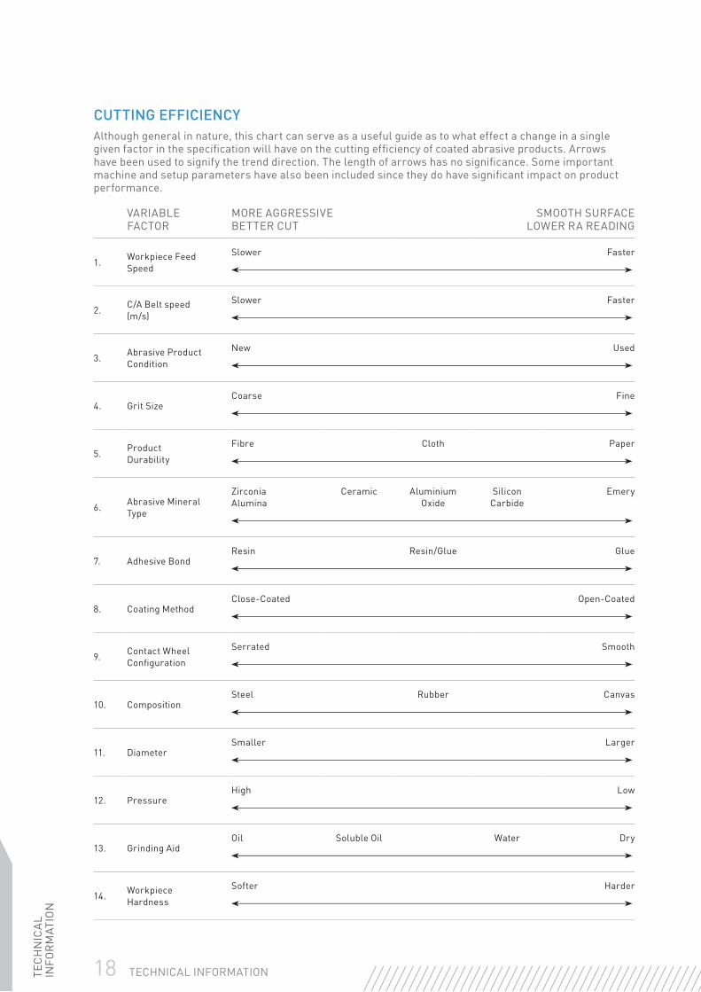
CUTTING EFFICIENCYAlthough general in nature, this chart can serve as a useful guide as to what effect a change in a single given factor in the specifi cation will have on the cutting effi ciency of coated abrasive products. Arrows have been used to signify the trend direction. The length of arrows has no signifi cance. Some important machine and setup parameters have also been included since they do have signifi cant impact on product performance.
VARIABLE FACTOR
MORE AGGRESSIVE BETTER CUT
SMOOTH SURFACELOWER RA READING
1. Workpiece Feed Speed
Slower Faster
2. C/A Belt speed (m/s)
Slower Faster
3. Abrasive ProductCondition
New Used
4. Grit SizeCoarse Fine
5. Product Durability
Fibre Cloth Paper
6. Abrasive Mineral Type
Zirconia Alumina
Ceramic Aluminium Oxide
Silicon Carbide
Emery
7. Adhesive BondResin Resin/Glue Glue
8. Coating MethodClose-Coated Open-Coated
9. Contact Wheel Confi guration
Serrated Smooth
10. CompositionSteel Rubber Canvas
11. DiameterSmaller Larger
12. PressureHigh Low
13. Grinding AidOil Soluble Oil Water Dry
14. Workpiece Hardness
Softer Harder

TEC
HN
ICA
L IN
FOR
MAT
ION
19TECHNICAL INFORMATION
Dry Wet
SAFETY ADVICESAFETY IN THE STORAGE & USE OF COATED ABRASIVESTRANSPORT & STORAGEAll coated abrasives should be handled carefully. Damage can be caused by mishandling, which should be avoided.
Coated abrasives should be stored in dry, frost free conditions. They should be kept away from heat sources, cold, damp walls, doors or windows and should not be in direct contact with the fl oor. Temperatures and humidity should be between 18°C and 22°C and 45%-65% relative humidity. Coated abrasives should not exposed to direct sunlight. Products should be kept in their original packaging until immediately before use. Once unpacked, they should be stored in a way which avoids distortion.
PERSONAL PROTECTIONSafety goggles, ear defenders, safety gloves, dust masks and, if conditions are severe, additional face protection. Leather aprons and safety shoes must be worn.
GENERAL PRECAUTIONSSafety instructions provided by the machine manufacturers must be followed. Where fi tted, all guards, covers and hoods must be in place on the machine during grinding, and should not be modifi ed in any way. Abrasives should not be used near infl ammable material or in an environment where there is a risk of explosion.
Sparks should be directed away from the face and body, if possible towards the fl oor. Dust extraction equipment must be used whenever it is available. The instructions for use given by the abrasive manufacturer must be followed e.g. ‘Not to be used without a support’, or ‘Not to be used for wet grinding’. The workpiece must be fi rmly fi xed before grinding starts. Check all abrasives visually before use and make certain that the product is suitable for the application. No modifi cations should be made to abrasive products after delivery.
When using a portable grinder always switch it off and allow the spindle to stop completely before putting the tool down. Wet grinding should only be carried out on machines designed for this purpose and with abrasives designated as suitable for this type of operation.
MouthProtection
WearGloves
EyeProtection
EarProtection
ReadInstructions

20 TECHNICAL INFORMATIONTEC
HN
ICA
L IN
FOR
MAT
ION
TUNGSTEN CARBIDE BURRS
DOs
✓ DO Always operate the burr within the recommended speed range
✓ DO Select the appropriate shape, diameter & cut style for the application
✓ DO Ensure the appropriate grinder is used & that it is regularly maintained
✓ DO Fix the maximum length of the burr in the collet (recommended max 10mm overhang)
✓ DO Check that the burr is running true in the grinder before use
✓ DO Securely fi x workpiece & hold the grinder fi rmly
✓ DO Use a smooth cutting action with constant movement in both directions.Use light pressure, letting the burr do the work
✓ DO For best fi nish, always end on a reverse stroke
DON’Ts
✘ DON’T Run burr above the Maximum Operating Speed
✘ DON’T Run burr too slowly (refer to recommended speed guide)
✘ DON’T Allow burr to be exposed to excessive mechanical or thermal shock
✘ DON’T Sink the burr to more than one-third of its periphery
✘ DON’T Jam the burr into grooves, crevices & cavities
✘ DON’T Allow burr to become too hot, causing braze to weaken (applies to burrs where head diameter is greater than shank diameter)
✘ DON’T Apply shock or excessive force to the product or let it overheat

TEC
HN
ICA
L IN
FOR
MAT
ION
21TECHNICAL INFORMATION
BEARTEXPRODUCT SELECTION - BY MACHINESTATIONARY MACHINESProduct selection guide & Starting Points recommendation
MACHINES PRODUCT DEBURRING CLEANING BLENDING & FINISHING
REQUIRED ACCESSORY
STRAIGHT SHAFT EQUIPMENT
Bench Grinder
Plain Discs n/a F2303 HS Med A F2520 VF A n/a
Convolute Wheels D19 SF DCS DMA 5AM Reduction
Bushings
Polybond Wheels C150-H10BTM n/a C240-D4BTM Reduction
Bushings
Flap Wheels n/a F2301 Med A F2501 VF A Reduction Bushings
Unitised Wheels U2301 8AM U2401 6AF U4401 2SF Reduction
Bushings
Lap Mops n/a F2520 VF A F2520 VF A n/a
Pedestal Grinder
Plain Discs n/a F2303 HS Med A F2520 VF A n/a
Convolute Wheels D19 SF DCS DMA 5AM Reduction
Bushings
Polybond Wheels C150-H10BTM n/a C240-D4BTM Reduction
Bushings
Flap Wheels n/a F2301 Med A F2501 VF A Reduction Bushings
Unitised Wheels U2301 8AM U2401 6AF U4401 2SF Reduction Bushings
BELT EQUIPMENT
Back Stand
Surface Blend Belts
DSB Coa or DSJ Ex Coa DSJ Med Superfl ex
Med n/a
Stroke Grinder
Surface Blend Belts DSB Coa DSJ Med Superfl ex
Med n/a
Centerless Polisher
Surface Blend Belts DSB Coa DSJ Med Superfl ex
Med n/a

22 TECHNICAL INFORMATIONTEC
HN
ICA
L IN
FOR
MAT
ION
MACHINES PRODUCT DEBURRING CLEANING BLENDING & FINISHING
REQUIRED ACCESSORY
FEED-THROUGH EQUIPMENT
Sheet/Coil Processing Machine
Surface Blend Belts DSB Coa DSJ Med Superfl ex Med n/a
Flap Wheels n/a F2301 Med A F2501 VF A Reduction Bushings
Convolute Wheels D18 SF DCS DMA 5AM Reduction
Bushings
Rotary Disc/ Planetary Disc Machine
Surface Blend Discs DSB Coa DSJ Med DSJ Med n/a
AUTOMATED EQUIPMENT
Rotary Machine
Plain Discs n/a F2303 HS Med A F2520 VF A n/a
Convolute Wheels D18 SF DCS DMA 5AM Reduction
Bushings
Polybond Wheels C150-H10BTM n/a C240-D4BTM Reduction
Bushings
Surface Blend Belts DSB Coa DSJ Med Superfl ex Med n/a
Unitised Wheels U2301 8AM U2401 6AF U4401 2SF Reduction
Bushings
Flap Wheels n/a F2301 Med A F2501 VF A Reduction
Bushings
Straight-Line Machine
Plain Discs n/a F2303 HS Med A F2520 VF A n/a
Convolute Wheels D18 SF DCS DMA 5AM Reduction
Bushings
Polybond Wheels C150-H10BTM n/a C240-D4BTM Reduction
Bushings
Surface Blend Belts DSB Coa DSJ Med Superfl ex Med n/a
Unitised Wheels U2301 8AM U2401 6AF U4401 2SF Reduction
Bushings
Flap Wheels n/a F2301 Med A F2501 VF A Reduction Bushings
Centerless Polisher
Surface Blend Belts DSB Coa DSJ Med Superfl ex Med n/a
Convolute Wheels D18 SF DCS DMA 5AM Reduction
Bushings
Polybond Wheels C150-H10BTM n/a C240-D4BTM Reduction
Bushings
SPECCHECK
MAXRPM
SPEC CHECKDid you pick the most effi cient solution?The most cost effective method usually involves getting the job done fast and effi ciently. The most dramatic savings come from labour expenses, rather than material costs.

TEC
HN
ICA
L IN
FOR
MAT
ION
23TECHNICAL INFORMATION
MACHINES PRODUCT DEBURRING CLEANING BLENDING & FINISHING
REQUIRED ACCESSORY
AUTOMATED EQUIPMENT
Robotic Equipment
Surface Blend Discs DSB Coa DSJ Med DSJ Med n/a
Convolute Wheels D18 SF DCS DMA 5AM Reduction
Bushings
Polybond Wheels C150-H10BTM n/a C240-D4BTM Reduction
Bushings
Surface Blend Belts DSB Coa DSJ Med Superfl ex Med n/a
Flap Wheels n/a F2301 Med A F2501 VF A Reduction Bushings
Plain Discs n/a F2303 HS Med A F2520 VF A n/a
Unitised Wheels U2301 8AM U2401 6AF U4401 2SF Reduction
Bushings
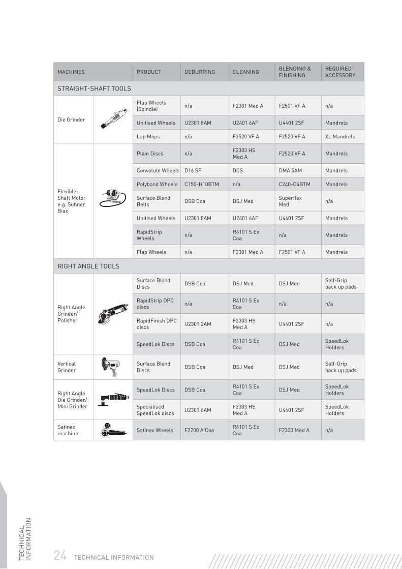
PORTABLE MACHINES
MACHINES PRODUCT DEBURRING CLEANING BLENDING & FINISHING
REQUIRED ACCESSORY
STRAIGHT-SHAFT TOOLS
Drill
Plain Discs n/a F2303 HS Med A F2520 VF A Mandrels
Convolute Wheels D16 SF DCS DMA 5AM Mandrels
Polybond Wheels C150-H10BTM n/a C240-D4BTM Mandrels
Flap Wheels (Spindle) n/a F2301 Med A F2501 VF A n/a
Unitised Wheels U2301 8AM U2401 6AF U4401 2SF Mandrels
RapidStrip Wheels/Discs n/a R4101 S Ex
Coa n/a Mandrels
Lap Mops n/a F2520 VF A F2520 VF A XL Mandrels
Straight-Shaft Grinder
Plain Discs n/a F2303 HS Med A F2520 VF A Mandrels
Convolute Wheels D19 SF DCS DMA 5AM Mandrels
Unitised Wheels U2301 8AM U2401 6AF U4401 2SF Mandrels
RapidStrip Wheels n/a R4101 S Ex
Coa n/a Mandrels
Flap Wheels (Spindle) n/a F2301 Med A F2501 VF A n/a
24 TECHNICAL INFORMATIONTEC
HN
ICA
L IN
FOR
MAT
ION
MACHINES PRODUCT DEBURRING CLEANING BLENDING & FINISHING
REQUIRED ACCESSORY
STRAIGHT-SHAFT TOOLS
Die Grinder
Flap Wheels (Spindle) n/a F2301 Med A F2501 VF A n/a
Unitised Wheels U2301 8AM U2401 6AF U4401 2SF Mandrels
Lap Mops n/a F2520 VF A F2520 VF A XL Mandrels
Flexible-Shaft Motor e.g. Suhner, Biax
Plain Discs n/a F2303 HS Med A F2520 VF A Mandrels
Convolute Wheels D16 SF DCS DMA 5AM Mandrels
Polybond Wheels C150-H10BTM n/a C240-D4BTM Mandrels
Surface Blend Belts DSB Coa DSJ Med Superfl ex
Med n/a
Unitised Wheels U2301 8AM U2401 6AF U4401 2SF Mandrels
RapidStrip Wheels n/a R4101 S Ex
Coa n/a Mandrels
Flap Wheels n/a F2301 Med A F2501 VF A Mandrels
RIGHT ANGLE TOOLS
Right Angle Grinder/ Polisher
Surface Blend Discs DSB Coa DSJ Med DSJ Med Self-Grip
back up pads
RapidStrip DPC discs n/a R4101 S Ex
Coa n/a n/a
RapidFinish DPC discs U2301 2AM F2303 HS
Med A U4401 2SF n/a
SpeedLok Discs DSB Coa R4101 S Ex Coa DSJ Med SpeedLok
Holders
Vertical Grinder
Surface Blend Discs DSB Coa DSJ Med DSJ Med Self-Grip
back up pads
Right Angle Die Grinder/Mini Grinder
SpeedLok Discs DSB Coa R4101 S Ex Coa DSJ Med SpeedLok
Holders
Specialised SpeedLok discs U2301 6AM F2303 HS
Med A U4401 2SF SpeedLok Holders
Satinex machine Satinex Wheels F2200 A Coa R4101 S Ex
Coa F2300 Med A n/a
TEC
HN
ICA
L IN
FOR
MAT
ION
25TECHNICAL INFORMATION
MACHINES PRODUCT DEBURRING CLEANING BLENDING & FINISHING
REQUIRED ACCESSORY
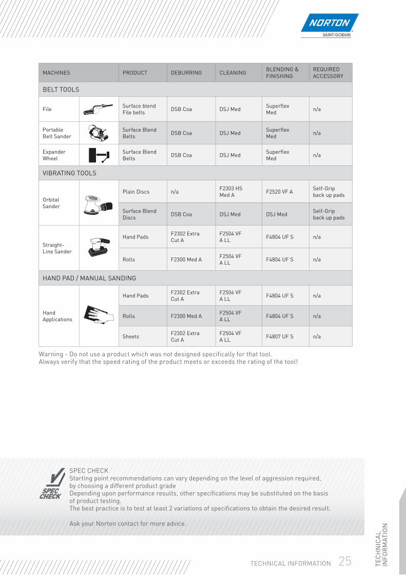
BELT TOOLS
File Surface blend File belts DSB Coa DSJ Med Superfl ex
Med n/a
Portable Belt Sander
Surface Blend Belts DSB Coa DSJ Med Superfl ex
Med n/a
Expander Wheel
Surface Blend Belts DSB Coa DSJ Med Superfl ex
Med n/a
VIBRATING TOOLS
Orbital Sander
Plain Discs n/a F2303 HS Med A F2520 VF A Self-Grip
back up pads
Surface Blend Discs DSB Coa DSJ Med DSJ Med Self-Grip
back up pads
Straight-Line Sander
Hand Pads F2302 Extra Cut A
F2504 VF A LL F4804 UF S n/a
Rolls F2300 Med A F2504 VF A LL F4804 UF S n/a
HAND PAD / MANUAL SANDING
Hand Applications
Hand Pads F2302 Extra Cut A
F2504 VF A LL F4804 UF S n/a
Rolls F2300 Med A F2504 VF A LL F4804 UF S n/a
Sheets F2302 Extra Cut A
F2504 VF A LL F4807 UF S n/a
Warning - Do not use a product which was not designed specifi cally for that tool. Always verify that the speed rating of the product meets or exceeds the rating of the tool!
SPECCHECK
MAXRPM
SPEC CHECKStarting point recommendations can vary depending on the level of aggression required, by choosing a different product gradeDepending upon performance results, other specifi cations may be substituted on the basis of product testing. The best practice is to test at least 2 variations of specifi cations to obtain the desired result.
Ask your Norton contact for more advice.
26 TECHNICAL INFORMATIONTEC
HN
ICA
L IN
FOR
MAT
ION
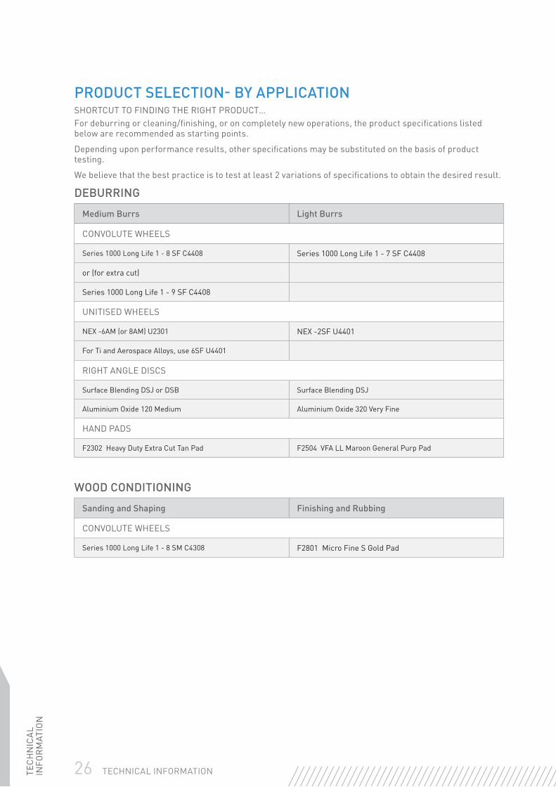
PRODUCT SELECTION- BY APPLICATIONSHORTCUT TO FINDING THE RIGHT PRODUCT…For deburring or cleaning/fi nishing, or on completely new operations, the product specifi cations listed below are recommended as starting points.
Depending upon performance results, other specifi cations may be substituted on the basis of product testing.
We believe that the best practice is to test at least 2 variations of specifi cations to obtain the desired result.
DEBURRING
Medium Burrs Light Burrs
CONVOLUTE WHEELS
Series 1000 Long Life 1 - 8 SF C4408 Series 1000 Long Life 1 - 7 SF C4408
or (for extra cut)
Series 1000 Long Life 1 - 9 SF C4408
UNITISED WHEELS
NEX -6AM (or 8AM) U2301 NEX -2SF U4401
For Ti and Aerospace Alloys, use 6SF U4401
RIGHT ANGLE DISCS
Surface Blending DSJ or DSB Surface Blending DSJ
Aluminium Oxide 120 Medium Aluminium Oxide 320 Very Fine
HAND PADS
F2302 Heavy Duty Extra Cut Tan Pad F2504 VFA LL Maroon General Purp Pad
WOOD CONDITIONING
Sanding and Shaping Finishing and Rubbing
CONVOLUTE WHEELS
Series 1000 Long Life 1 - 8 SM C4308 F2801 Micro Fine S Gold Pad

TEC
HN
ICA
L IN
FOR
MAT
ION
27TECHNICAL INFORMATION
CLEANING AND FINISHING
Clean / Medium Grain Finishing Fine Grain Finishing
CONVOLUTE WHEELS
DSS Surf Fin S/C Med Wheel C4302 DCS Clean/Finish S/C Fine Wheel C4401
or or
Series 1000 Long Life 1 - 6 SM, C4308 Series 1000 Long Life 1 - 6 SF C4408
UNITISED WHEELS
NEX -4AF U2401 NEX -2SF U4401
FLAP WHEELS
Med Grit Aluminium Oxide F2301 Fine Grit Aluminium Oxide F2401
Medium Density Flap Wheel Medium Density Flap Wheel
HAND PADS
F2504 VFA LL Maroon General Purp F2801 Micro Fine S Gold Pad
or
F4300 Medium S Pad for stainless steel
HAND PAD APPLICATIONS
Heavy Duty Cleaning & rust removal
Medium Cleaning Light Cleaning & Finishing
HAND PADS
F2302 Heavy Duty Extra Cut Pad
Tan
F2504 VFA LL General Purpose Pad
Maroon
F2801 Mfi ne S Pad
Gold
28 TECHNICAL INFORMATIONTEC
HN
ICA
L IN
FOR
MAT
ION
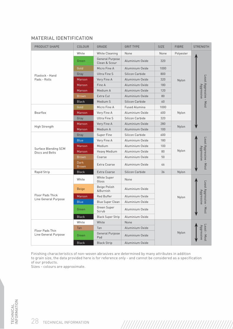
MATERIAL IDENTIFICATION
PRODUCT SHAPE COLOUR GRADE GRIT TYPE SIZE FIBRE STRENGTH
Flastock - HandPads - Rolls
White White Cleaning None None Polyester
Least Aggressive - Most
Aggressive
Green General Purpose Clean & Scour Aluminium Oxide 320
Nylon
Gold Micro Fine A Aluminium Oxide 1000
Gray Ultra Fine S Silicon Carbide 800
Maroon Very Fine A Aluminium Oxide 320
Maroon Fine A Aluminium Oxide 180
Maroon Medium A Aluminium Oxide 120
Brown Extra Cut Aluminium Oxide 80
Black Medium S Silicon Carbide 60
Bearfl ex
Gold Micro Fine A Fused Alumina 1000
NylonMaroon Very Fine A Aluminium Oxide 600
Gray Ultra Fine S Silicon Carbide 320
High StrengthMaroon Very Fine A Aluminium Oxide 280
NylonMaroon Medium A Aluminium Oxide 100
Surface Blending SCMDiscs and Belts
Gray Super Fine Silicon Carbide 600
Nylon
Least Aggressive - Most
Aggressive
Blue Very Fine A Aluminium Oxide 180
Maroon Medium Aluminium Oxide 100
Maroon Heavy Medium Aluminium Oxide 80
Brown Coarse Aluminium Oxide 50
Dark Brown Extra Coarse Aluminium Oxide 46
Rapid Strip Black Extra Coarse Silicon Carbide 36 Nylon
Floor Pads ThickLine General Purpose
White White Super Gloss None
Nylon
Least Aggressive - Most
Aggressive
Beige Beige Polish &Burnish Aluminium Oxide
Maroon Red Buffer Aluminium Oxide
Blue Blue Super Clean Aluminium Oxide
Green Green Super Scrub Aluminium Oxide
Black Black Super Strip Aluminium Oxide
Floor Pads ThinLine General Purpose
White White None
Nylon
Least - Most
Aggressive
Tan Tan Aluminium Oxide
Green General Purpose Pad Aluminium Oxide
Black Black Strip Aluminium Oxide
Finishing characteristics of non-woven abrasives are determined by many attributes in addition to grain size, the data provided here is for reference only - and cannot be considered as a specifi cation of our products.Sizes - colours are approximate.

TEC
HN
ICA
L IN
FOR
MAT
ION
29TECHNICAL INFORMATION
SAFETY ADVICE - DO’S & DON’TSFor your safety you should ensure that you are fully aware of how to safely use abrasives
✓ DO Read the safety instructions provided by the abrasives and equipment supplier
✓ DO Store abrasives in dry, frost-free conditions avoiding wide variations in temperature
✓ DO Ensure that the product is suitable for its purpose
✓ DO Handle, store and transport products with care
✓ DO Disconnect the power to the machine before fi tting the product
✓ DO Examine all products before mounting and periodically during use for possible defects or damage (core fl atness, fatigue cracks, undercutting, arbor hole damage...)
✓ DO Check that correct mounting devices are used and that they are clean, undistorted and free from burrs
✓ DO Ensure that work rests are properly adjusted and secure
✓ DO Always use a correctly designed and adjusted guard (on belts)
✓ DO Ensure that the workpiece is secure
✓ DO Wear appropriate personal protective equipment at all times
✓ DO Avoid clogging and uneven wear to ensure that the product is working effi ciently
✓ DO Ensure accordance between product direction arrow / machine rotation
✓ DO Ensure that all machines using abrasives meet the requirements of the current european machinery directives-CE
✓ DO
Be aware of the hazards likely during the use of abrasives and observe the recommended precautions to be taken:
• Bodily contact with the abrasive product at operating speed
• Injury resulting from product breakage during use
• Grinding debris, sparks, fumes and dust generated by the grinding process
• Noise
• Vibration

30 TECHNICAL INFORMATIONTEC
HN
ICA
L IN
FOR
MAT
ION
SAFETY ADVICE - DO’S & DON’TSFor your safety you should ensure that you are fully aware of how to safely use abrasives.
✘ DON’T Allow untrained people to use abrasives
✘ DON’T Use a product that is damaged
✘ DON’T Use a product if it cannot be properly identifi ed
✘ DON’T Use a machine that is not in good working order or one with defective parts
✘ DON’T Force the abrasive onto the mounting device or modify the size of the mounting hole
✘ DON’T Exceed the maximum operating speed marked on the product
✘ DON’T Apply shock or excessive force to the product or let it overheat
✘ DON’T Use mounting fl anges which are not clean and fl at
✘ DON’T Tighten the mounting device excessively
✘ DON’T Start the machine until the guard is in place and fastened securely
✘ DON’T Continue to use a product if vibration occurs. True or replace it
✘ DON’T Grind on the part of the product which is not designed for the operation
✘ DON’T Start the machine with the workpiece in contact with the abrasive product
✘ DON’T Grind material for which the product is not designed
✘ DON’T Stop the abrasive by applying pressure to its surface, let it stop naturally
✘ DON’T Wear loose clothing, ties and jewellery
✘ DON’T Use abrasive products near fl ammable materials

TEC
HN
ICA
L IN
FOR
MAT
ION
31TECHNICAL INFORMATION
UNDERSTANDING THE SPECIFICATIONABRASIVE GRIT SIZE GRADE STRUCTURE BOND
ALUMINIUMOXIDE
SILICON CARBIDE
CERAMICALUMINIUM
OXIDECOARSE MEDIUM FINE SOFT MEDIUM HARD CLOSED OPEN
A 37C SGB 12 30 80 E I Q 5 10 VS
19A 39C 3SG 16 36 90 F J R 11 VXP
25A 5SG 20 46 100 G K S 12 VXPM
38A 1TGP 24 54 120 H L T VTECH
40A 60 M
57A 70 N
86A O
IPA 60 EH 17 VTX
XH 20
ES5 60 80 J L VX
K
BONDED ABRASIVESTECHNICAL INFORMATIONWHAT IS A GRINDING WHEEL?A grinding wheel is a precision tool with thousands of cutting points. It consists of abrasive grains held in a matrix of bond and separated by pores. The abrasive grains are the cutting points while the purpose of the bond is to hold the individual grains together. The pores (hollow spaces between adjacent abrasive grains and the bond) serve to provide clearance for coolant penetration and metal chips removed in the grinding process.
When the wheel is rotated at grinding speed and applied to the workpiece, the abrasive grains cut the material that is being ground, removing the material in small chips.
Under the action of the forces imposed during grinding the abrasive cutting points are worn fl at, resulting in the points becoming blunt. This causes an increase in friction, and a build up of heat.
The increase in grinding forces causes either the abrasive to fracture, exposing new cutting edges, or fractures the bond bridges holding the abrasive grains. In the latter case fresh abrasive grains are exposed to cut the workpiece.
In normal vitrifi ed grinding applications the wheel has to be dressed.
By varying the properties of the abrasive, the type of bond, the make-up of the wheel, it is possible to produce grinding wheels with a vast range of different grinding characteristics.
ABRASIVESModern synthetic abrasives allow accurate control over the physical properties and form of the abrasive grain. This helps to ensure that grinding wheels can be manufactured with consistent cutting properties.
Norton offers a comprehensive selection of abrasive types to provide a wide range of specifi c grinding characteristics. This is necessary for maximum effi ciency in the large variety of operations demanded by the industry today.
Abrasive Grain SizeThe grain or grit size is most important in determining a wheel’s ability to achieve the required surface fi nish and remove stock. The size is designated by a number which increases as grain size decreases. For example 10 grit has a median size of about 2,0mm and 60 grit 0,25mm.
Standard sizes are used in all Norton wheels as specifi ed in the European Standards laid down by FEPA.
An ideal grinding abrasive has the ability to stay sharp with minimum point dulling, and when dulling begins it fractures revealing new sharp cutting edges. Abrasive grains used in the manufacture of bonded abrasives come in three main categories.
32 TECHNICAL INFORMATIONTEC
HN
ICA
L IN
FOR
MAT
ION
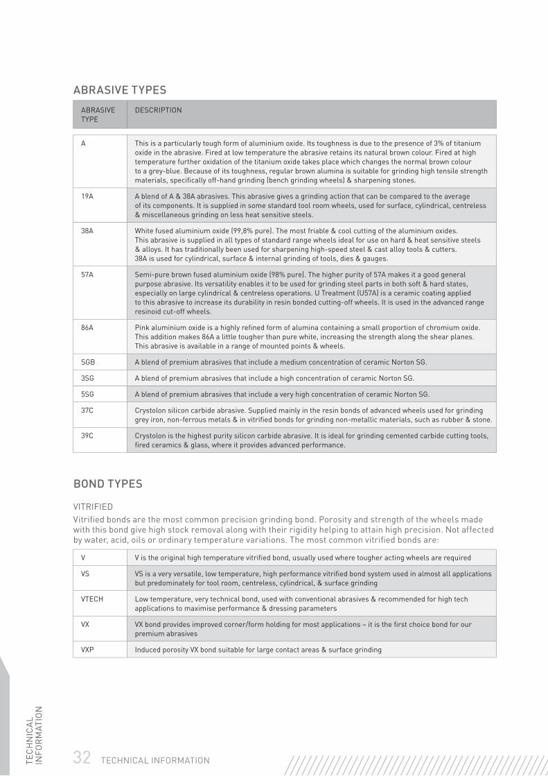
ABRASIVE TYPES
ABRASIVE TYPE
DESCRIPTION
A This is a particularly tough form of aluminium oxide. Its toughness is due to the presence of 3% of titanium oxide in the abrasive. Fired at low temperature the abrasive retains its natural brown colour. Fired at high temperature further oxidation of the titanium oxide takes place which changes the normal brown colour to a grey-blue. Because of its toughness, regular brown alumina is suitable for grinding high tensile strength materials, specifi cally off-hand grinding (bench grinding wheels) & sharpening stones.
19A A blend of A & 38A abrasives. This abrasive gives a grinding action that can be compared to the average of its components. It is supplied in some standard tool room wheels, used for surface, cylindrical, centreless & miscellaneous grinding on less heat sensitive steels.
38A White fused aluminium oxide (99,8% pure). The most friable & cool cutting of the aluminium oxides. This abrasive is supplied in all types of standard range wheels ideal for use on hard & heat sensitive steels & alloys. It has traditionally been used for sharpening high-speed steel & cast alloy tools & cutters. 38A is used for cylindrical, surface & internal grinding of tools, dies & gauges.
57A Semi-pure brown fused aluminium oxide (98% pure). The higher purity of 57A makes it a good general purpose abrasive. Its versatility enables it to be used for grinding steel parts in both soft & hard states, especially on large cylindrical & centreless operations. U Treatment (U57A) is a ceramic coating applied to this abrasive to increase its durability in resin bonded cutting-off wheels. It is used in the advanced range resinoid cut-off wheels.
86A Pink aluminium oxide is a highly refi ned form of alumina containing a small proportion of chromium oxide. This addition makes 86A a little tougher than pure white, increasing the strength along the shear planes. This abrasive is available in a range of mounted points & wheels.
SGB A blend of premium abrasives that include a medium concentration of ceramic Norton SG.
3SG A blend of premium abrasives that include a high concentration of ceramic Norton SG.
5SG A blend of premium abrasives that include a very high concentration of ceramic Norton SG.
37C Crystolon silicon carbide abrasive. Supplied mainly in the resin bonds of advanced wheels used for grinding grey iron, non-ferrous metals & in vitrifi ed bonds for grinding non-metallic materials, such as rubber & stone.
39C Crystolon is the highest purity silicon carbide abrasive. It is ideal for grinding cemented carbide cutting tools, fi red ceramics & glass, where it provides advanced performance.
BOND TYPES
VITRIFIEDVitrifi ed bonds are the most common precision grinding bond. Porosity and strength of the wheels made with this bond give high stock removal along with their rigidity helping to attain high precision. Not affected by water, acid, oils or ordinary temperature variations. The most common vitrifi ed bonds are:
V V is the original high temperature vitrifi ed bond, usually used where tougher acting wheels are required
VS VS is a very versatile, low temperature, high performance vitrifi ed bond system used in almost all applications but predominately for tool room, centreless, cylindrical, & surface grinding
VTECH Low temperature, very technical bond, used with conventional abrasives & recommended for high tech applications to maximise performance & dressing parameters
VX VX bond provides improved corner/form holding for most applications – it is the fi rst choice bond for our premium abrasives
VXP Induced porosity VX bond suitable for large contact areas & surface grinding

TEC
HN
ICA
L IN
FOR
MAT
ION
33TECHNICAL INFORMATION
BOND TYPES
ORGANICThese bonds are used in two types of wheels. Firstly, wheels used on portable or fi xed machines for the rapid removal of metal. Secondly, cutting-off wheels either un-reinforced or reinforced, for use on portable or fi xed machines. The most common organic bonds are:
SNAGGING WHEELS & CUPS
B & B3 Foundry wheels: multi-purpose bond that gives satisfactory results on most applications
B28 Foundry wheels: high level bond suitable for most technical applications requiring high powered machines
CUTTING-OFF WHEELS
BF1 Specifi c bond ensuring the best quality of cut in dry or wet conditions
BF3 New generation bond assuring the best wheel life in dry cutting operations; versatile & long wheel life. Ideal for heavy duty operations
B24 New generation bond used on silicon carbide cut-off wheels that gives the best performance & the ultimate cut quality on non-ferrous metals in wet conditions
B25 Standard multi-purpose bond that offers durability & freeness of cut in a wide variety of materials & applications. Can also be used in wet cutting on softer grades
B26 New generation bond used on aluminium oxide cut-off wheels that gives the best performance & the ultimate cut quality on ferrous metals in wet conditions
B65 Traditional bond gives good performance & long wheel life in dry cutting conditions
WHEEL GRADESThe grade indicates the relative holding power of the bond, which holds abrasive grains in a wheel. This is represented in the specifi cation by letters running through the alphabet from hardest to softest. The following rules should be followed with regard to grade:
USE SOFT GRADE• For hard materials such as hard tool steels
& carbides
• For large areas of contact
• For rapid stock removal
USE HARD GRADE• For soft materials
• For small or narrow areas on contact
• For longer wheel life
COMMON RANGE OF GRADES
E F G H I J K L M N O P Q R S T U
CYLINDRICAL/CENTRELESS
SURFACE GRINDING
ID GRINDING
TOOL GRINDING
THREAD GRINDING
NON-REINFORCED ORGANIC
REINFORCED ORGANIC
34 TECHNICAL INFORMATIONTEC
HN
ICA
L IN
FOR
MAT
ION
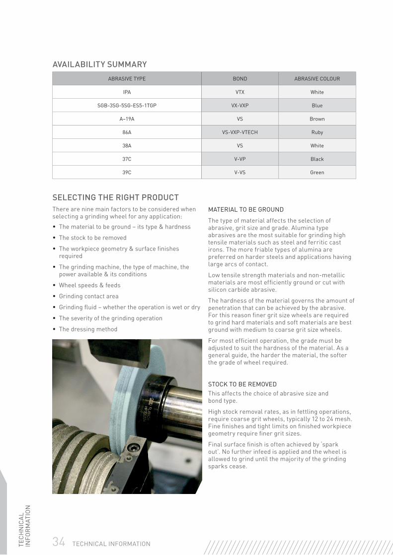
AVAILABILITY SUMMARY
ABRASIVE TYPE BOND ABRASIVE COLOUR
IPA VTX White
SGB-3SG-5SG-ES5-1TGP VX-VXP Blue
A–19A VS Brown
86A VS-VXP-VTECH Ruby
38A VS White
37C V-VP Black
39C V-VS Green
SELECTING THE RIGHT PRODUCTThere are nine main factors to be considered when selecting a grinding wheel for any application:
• The material to be ground – its type & hardness
• The stock to be removed
• The workpiece geometry & surface fi nishes required
• The grinding machine, the type of machine, the power available & its conditions
• Wheel speeds & feeds
• Grinding contact area
• Grinding fl uid – whether the operation is wet or dry
• The severity of the grinding operation
• The dressing method
MATERIAL TO BE GROUND
The type of material affects the selection of abrasive, grit size and grade. Alumina type abrasives are the most suitable for grinding high tensile materials such as steel and ferritic cast irons. The more friable types of alumina are preferred on harder steels and applications having large arcs of contact.
Low tensile strength materials and non-metallic materials are most effi ciently ground or cut with silicon carbide abrasive.
The hardness of the material governs the amount of penetration that can be achieved by the abrasive. For this reason fi ner grit size wheels are required to grind hard materials and soft materials are best ground with medium to coarse grit size wheels.
For most effi cient operation, the grade must be adjusted to suit the hardness of the material. As a general guide, the harder the material, the softer the grade of wheel required.
STOCK TO BE REMOVEDThis affects the choice of abrasive size and bond type.
High stock removal rates, as in fettling operations, require coarse grit wheels, typically 12 to 24 mesh. Fine fi nishes and tight limits on fi nished workpiece geometry require fi ner grit sizes.
Final surface fi nish is often achieved by ‘spark out’. No further infeed is applied and the wheel is allowed to grind until the majority of the grinding sparks cease.

TEC
HN
ICA
L IN
FOR
MAT
ION
35TECHNICAL INFORMATION
Usage Key Highly recommended
SURFACE FINISH & GRIT SIZE
SURFACE FINISH GRAIN SIZE
µ in CLA µ m Ra 46 60 80 100 120 150 180 220
42 1,10
32 0,80
26 0,70
21 0,50
16 0,40
14 0,35
11 0,25
8 0,20
7 0,17
6 0,14
5 0,12
4 0,10
3 0,08
2 0,05
MIN FORM RADIUS
METRIC (mm) 0,75 0,50 0,40 0,25 0,20 0,18 0,13 0,10
IMP INS ,030 ,020 ,015 ,010 ,008 ,007 ,005 ,004
SURFACE FINISH
The achievable surface fi nish in any grinding operation is highly dependent upon the grit size of the grinding wheel. The following chart shows the range of surface fi nishes achievable when using grinding wheels of different grit sizes on conventional precision grinding applications, together with the minimum form radius that can be ground using each grit size.
Other factors can affect the surface fi nish achieved. In particular:
• Production grinding applications, with higher stock removal ranges, will give surface fi nishes at the coarser end of the range
• Plunge grinding applications will often require the selection of a grit size one size fi ner than shown
• Dressing techniques & the type of material can also affect the surface fi nish achieved
ACHIEVING IMPROVED SURFACE FINISHES
By changing the wheel dressing technique, it is possible to achieve fi ner surface fi nishes than those shown. As well as reducing the dresser infeed per revolution of the grinding wheel, it is also possible to reduce the infeed and traverse rate when grinding, thus reducing the stock removal rate. Obviously this approach will have limited application in production grinding but it can be very useful in tool room work.

36 TECHNICAL INFORMATIONTEC
HN
ICA
L IN
FOR
MAT
ION
THE GRINDING MACHINEThe type of machine can effectively defi ne the grinding contact area and the ease with which grinding fl uid can be applied to the grinding zone.
The power available on the machine governs the stock removal rate. The greater the power available, the harder the grade of wheel that is required for effi cient operation.
Any deterioration in the condition of machine bearings and slideways will lead to vibration and, consequently, premature wheel breakdown. This can, in part, be overcome by using a harder grade wheel and/or a tougher abrasive but the only effective solution is to maintain the machine as recommended by the machine manufacturer.
SPEEDS & FEEDSThe effect of speeds and feeds on grinding action and, hence, the selection of wheel, can best be summarised in the following table:
GRINDING CONTACT AREA
The contact area affects the selection of wheel grade and structure. Large contact areas, as on segmental grinders, generally produce low grinding pressures and require soft grade, open structure wheels. Induced porosity wheels are most effi cient for grinding very large contact areas. Conversely, small contact areas, as on cylindrical grinding machines, require harder grade and/or closer structure wheels.
The size of workpiece can also affect the grinding contact area. In general, the larger the workpiece, relative to the grinding wheel diameter, the larger the contact area, requiring softer grade wheels.
GRINDING FLUIDDry grinding with vitrifi ed wheels require wheels one or two grades softer than when wet grinding.
SEVERITY OF THE GRINDING OPERATIONThis can affect the choice of abrasive type, grade and even bond type. Where the wheel is subjected to shock loads, as in fettling operations, a resinoid bond should be used. In general, the more severe the grinding operation, the harder the grade of wheel required and the tougher the abrasive that can be used. Severity of grinding operation can be due to heavy infeeds, high work speeds and traverse rates or intermittent grinding contact. The latter is usually due to workpiece geometry, resulting in a dressing action on the wheel.
GRINDING WHEEL DRESSING & TRUINGTruing and dressing of grinding wheels are often considered to be the same thing, since they are frequently performed as one operation. Truing is performed to ensure concentricity and introduce any profi le that may be required on the wheel face. Dressing conditions the wheel surface to give the desired cutting action.
EFFECT ON GRINDING ACTION
SPEED INCREASED DECREASED
Wheel speed* Harder Softer
Work speed Softer Harder
Traverse speed Softer Harder
Infeed rate Softer Harder
*The maximum peripheral speed (m/s) specifi ed for the wheel must never be exceeded

TEC
HN
ICA
L IN
FOR
MAT
ION
37TECHNICAL INFORMATION
SINGLE & MULTI-POINT DIAMONDSDiamonds are the fi rst choice where close tolerances, fi ne fi nishes, speed and fl exibility are required. Since diamond dressing is primarily a machining operation rather than a crushing operation, the surface formed on the wheel is closer than that obtained from mechanical dressers. This results in a slower cutting wheel with better form holding characteristics and superior fi nish control.
By varying the depth of cut per pass made by the diamond and changing the traverse rate, different wheel surfaces, and hence different cutting actions, can be achieved.
The following are general recommendations for dressing with single-point diamonds.
DIAMOND SIZE
The size of diamond is important when selecting a dressing tool and several factors are relevant in this selection, e.g. large, coarse grit wheels require a larger diamond than smaller, fi ne grit wheels. If a fi ne fi nish is required, the use of a diamond which is too large can adversely affect the fi nish and cancel the effect of fi ne grit selection. The trend today is away from single-point dressers and towards multi-point dressers employing a matrix shape to suit the form required.
A useful formula for determining single-point & multi-point diamond size is:
Wheel diameter (mm) x Wheel thickness (mm)
ROUGHING FINISHING
Diamond infeed mm per pass 0,025mm 0,012-0,020mm
Diamond traverse rate mm/wheel rev. 0,18mm 0,10mm
The diamond should always be applied at the centreline of the wheel with a 5°-15° drag angle.
SINGLE-POINT MULTIPLY THE DIAMETER OF THE WHEEL BY ITS THICKNESS
Dia
met
er Thickness
Diameter x Thickness (mm) Carat
<6000 0,33 Carat
6000-18000 0,50 Carat
>18000 1,0 Carat
For best results, always use a coolant when dressing
MULTI-POINT MULTIPLY THE DIAMETER OF THE WHEEL BY ITS THICKNESS
Dia
met
er Thickness
Diameter x Thickness (mm) Carat
<30000 1,3 Carat
30000-60000 2,5 Carat
>60000 5,0 Carat
For best results, always use a coolant when dressing
COOLANT
Dressing with diamonds should always be carried out using a copious supply of coolant. The coolant should always be turned on fully before the diamond touches the wheel. The diamond life will deteriorate rapidly if it is allowed to become hot and then cooled rapidly as can be experienced with an intermittent coolant fl ow.
ROTATION OF THE DRESSING TOOLTo ensure maximum diamond life, single-point and conical cluster diamond dressing tools should be systematically rotated after every four or fi ve dressings to ensure that the keen edge generated from the drag angle is constantly presented to the wheel.

38 TECHNICAL INFORMATIONTEC
HN
ICA
L IN
FOR
MAT
ION
WHEEL BORE (mm) REDUCED TO (mm) REDUCTION RING
50,8 35 07660704766
32 25 07660717540
32 20 07660717538
31,75 15,88 07660704757
31,75 12,7 07660704755
20 16 07660717530
20 15 07660717529
20 13 07660717527
20 12 07660717525
20 10 07660717524
16 6 00510008919
REDUCTION RINGSPlastic reduction rings may be used to adapt grinding wheels to fi t on various spindle sizes. These rings reduce the bore hole size, allowing the wheel to be safely mounted on a spindle with a smaller diameter.
• Reduction rings should never come in contact with the fl ange
• Reduction rings should not be used on wheels of thicknesses less than 6mm, nor greater than 50mm
• Always use one reduction ring on each side of the wheel when the wheel is thick enough to allow correct seating
• Never use reduction rings to reduce the hole below the minimum specifi ed in the FEPA safety code
Reduced bore (mm)15
20Wheel bore (mm)
TEC
HN
ICA
L IN
FOR
MAT
ION
39TECHNICAL INFORMATION
MOUNTINGA wheel should only be mounted onto the machine for which it was intended. The speed of the spindle on which the wheel is mounted should not under any circumstances exceed the maximum RPM speed specifi ed for the wheel when it is full size. The wheel should fi t freely, but not loosely, onto the spindle or spigot diameter of the fl ange plates. Wheels, blotting paper washers and fl anges should be free from foreign matter. Certain wheels have a positioning mark (Mount Down or Mount Up) marked on them. Care must be taken to ensure that this mark occupies the position stated by the manufacturer.
REDUCING BUSHESWhere a removable bush is used as a means of reducing the bore of an abrasive wheel, care must be taken to ensure the bushes should not project beyond the side of the wheel and the wheel blotter. The clamping faces of the fl ange plates MUST clamp on the mounting washers attached to the wheel and not on any part of the reducing bush. Reducing bushes should never be used on wheels less than 6mm thick or on products with a back or web of less than 6mm. Never use plastic bushes on wheels used with portable grinding equipment.
MOUNTING WASHERSBlotters should be used with all grinding wheels unless there is a specifi c exemption. Blotters should be slightly larger in diameter than the mounting fl anges and free from any scuffs, wrinkles or other damage.
MOUNTING FLANGESMounting fl anges are designed to clamp the wheel to the machine and transfer the driving forces from the machine spindle to the grinding wheel. They should be designed to take the driving forces away from the area around the grinding wheel bore and generally should be not less than one third of the grinding wheel diameter.
Flange surfaces should be fl at, free from burrs, bumps, bruises and other damage. Flanges should be of equal diameter, have equal bearing surfaces and be properly recessed or undercut.
The rear fl ange must be positively driven by the machine spindle, being either keyed or shrunk onto the spindle.
Flanges must run true to the machine spindle.
Clamping nuts (centre nut locking) should only be tightened suffi ciently to hold the wheel securely without slippage and must not be over-tightened. When fl anges are clamped by a series of screws, they should be tightened in stages uniformly in a diametric sequence.
In most instances it is appropriate to tighten the nut or screws by hand with the correct tool (spanner or hexagonal socket key) until they stop turning. By adopting this technique it is very rare that the wheel would be under-tightened and impossible to over-tighten the wheel. Bolts for mounting wheels with inserted nuts should be long enough to engage an adequate length of thread, i.e. equal to the thread diameter, but must not protrude through the nut insert.
For recommended designs of fl anges, refer to the FEPA Safety Guidelines.
CAUTIONAfter mounting or re-mounting a grinding wheel on a machine, stand well clear, ensuring that there are no persons in line with the wheel and allow the wheel to run free for two minutes. A re-mounted wheel should always be treated as if it were a new wheel.
TYPE 06 CUP WHEELS – FIXED MACHINESThe diameter of the fl ange and paper washer inside the cup must be smaller than the diameter of the cup recess to avoid any risk of radial pressure on the wheel. When used for work heavier than light tool and cutter grinding, the back fl ange may be larger than that inside the cup but the recess diameter of both fl anges must be equal.
MOUNTED POINTS & WHEELSThe spindle dimensions of the mounted point must be suitable for the collet being used, and the spindle overhang corresponding to the machine speed should be observed.
TYPE 31 GRINDING SEGMENTSSegments are held by special chucks with suitable provision for adjustment to compensate for segment wear. To prevent breakages segments should not protrude more than 1,5 times their thickness from the clamping chuck face, and should be mounted with markings uppermost.
40 TECHNICAL INFORMATIONTEC
HN
ICA
L IN
FOR
MAT
ION
WHEEL BALANCEMost Norton grinding wheels are balance corrected to a minimum of ISO Standards. Precision grinding machines usually provide methods of accurately balancing the complete wheel and fl ange assembly. Modern production machines are now supplied with automatic balancing systems, whereas, tool room and older production machines still have to be manually balanced, ensuring the best possible grinding performance from the wheel.
The balancing procedure can be carried out either on a special balancing stand or in-situ on the machine. The machine manufacturer’s instructions should be closely followed. There are many methods of manually balancing the wheel assembly, depending upon the number of balance weights in the wheel arbour. A typical ‘two weight’ balancing system technique is described below:
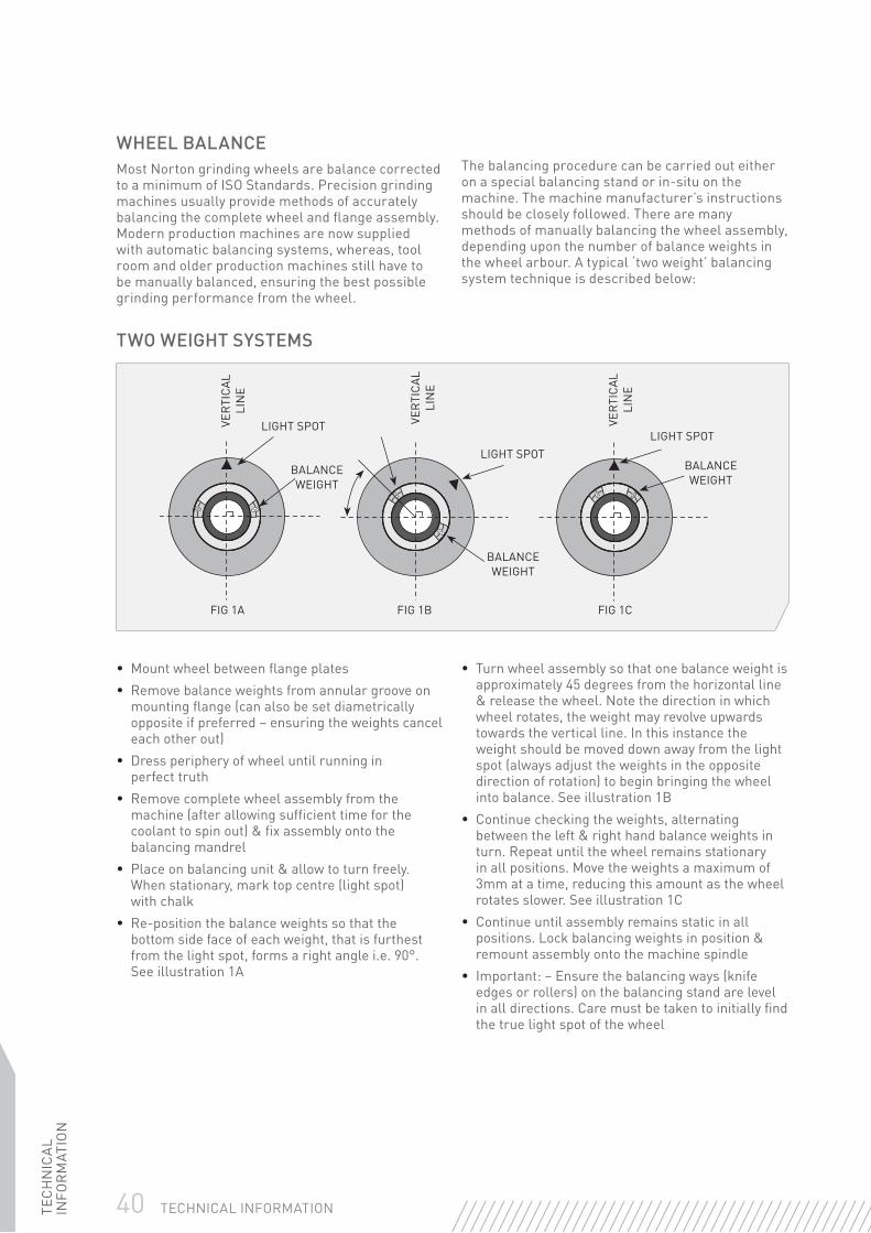
TWO WEIGHT SYSTEMS
• Mount wheel between fl ange plates• Remove balance weights from annular groove on
mounting fl ange (can also be set diametrically opposite if preferred – ensuring the weights cancel each other out)
• Dress periphery of wheel until running in perfect truth
• Remove complete wheel assembly from the machine (after allowing suffi cient time for the coolant to spin out) & fi x assembly onto the balancing mandrel
• Place on balancing unit & allow to turn freely. When stationary, mark top centre (light spot) with chalk
• Re-position the balance weights so that the bottom side face of each weight, that is furthest from the light spot, forms a right angle i.e. 90°. See illustration 1A
• Turn wheel assembly so that one balance weight is approximately 45 degrees from the horizontal line & release the wheel. Note the direction in which wheel rotates, the weight may revolve upwards towards the vertical line. In this instance the weight should be moved down away from the light spot (always adjust the weights in the opposite direction of rotation) to begin bringing the wheel into balance. See illustration 1B
• Continue checking the weights, alternating between the left & right hand balance weights in turn. Repeat until the wheel remains stationary in all positions. Move the weights a maximum of 3mm at a time, reducing this amount as the wheel rotates slower. See illustration 1C
• Continue until assembly remains static in all positions. Lock balancing weights in position & remount assembly onto the machine spindle
• Important: – Ensure the balancing ways (knife edges or rollers) on the balancing stand are level in all directions. Care must be taken to initially fi nd the true light spot of the wheel
FIG 1A FIG 1B FIG 1C
VER
TICA
L LI
NE
VER
TICA
L LI
NE
VER
TICA
L LI
NE
LIGHT SPOT
LIGHT SPOTLIGHT SPOT
BALANCE WEIGHT
BALANCE WEIGHT
BALANCE WEIGHT

TEC
HN
ICA
L IN
FOR
MAT
ION
41TECHNICAL INFORMATION
TROUBLESHOOTINGSOLVING SURFACE FINISH PROBLEMSMany problems associated with grinding relate to surface fi nish defects. The following chart describes some common surface fi nish problems, shows the probable causes and suggests remedies to cure the problem.
REGULAR SPACED CHATTER MARKSImmediately after dressing
Cause Machine vibration
Solution Check for wear in machine bearings
REGULAR SPACED CHATTER MARKSAfter a period of time
Cause Wheel too hard
Solution Use softer grade of wheel
CHEQUERED PATTERN
Cause Wheel out of balance
Solution Balance wheel
CHATTER MARKS
Cause Wheel out of truth
Solution Re-dress wheel
IRREGULAR CHATTER MARKS
Cause Wheel mounting insecure
Solution Tighten wheel mounting
Cause Workpiece centres loose
Solution Adjust centres
SPIRAL MARKS
Cause Dressing techniques
Solution Check diamond is sharp & secure
Cause Dressing techniques
Solution Check dress is parallel
FINISH TOO COARSE
Cause Grit size too coarse
Solution Use fi ne, slow traverse dress
Cause Wheel too soft
Solution Decrease workspeed. Use harder grade wheel
Cause Metal pick-up on wheel
Solution Dress more frequently. Use more open, softer grade wheel

42 TECHNICAL INFORMATIONTEC
HN
ICA
L IN
FOR
MAT
ION
SAFETY ADVICESAFETY IN THE STORAGE & USE OF GRINDING WHEELSStringent safety standards are maintained throughout the manufacture of Norton Grinding Wheels. To reduce the risk of accidents further, the law requires that certain basic precautions are taken in the storage and use of abrasive wheels.
RECEIPTOn receipt, grinding wheels should be thoroughly examined to see if they show any signs of damage, such as chips, cracks or discolouration. Damaged wheels must not be used.
HANDLINGAny mishandling that results in the wheel being subjected to any shock loading can damage all grinding wheels. This can occur if the wheel is inadvertently dropped, knocked over or banged against any other object. This is equally true if the wheel is secured on a pallet, which has been dropped heavily from a forklift truck.
Any grinding wheel subjected to such mishandling should be carefully examined for signs of damage. If in any doubt – do not use.
STORAGESmall wheels up to 80mm diameter, together with cones, plugs, mounted points and wheels may be stored in suitable bins, drawers or boxes. Type 02 cylinder wheels, type 06 straight cup wheels, type 12 dish wheels and type 13 saucer wheels should normally be stacked on fl at sides with cushioning material between them. Thick rim and hard grade cylinder and straight cup wheels may be stored on their periphery as for plain wheels. Soft grade, straight cup wheels, and all type 11 taper cup wheels, should be stored base to base and rim to rim, to prevent chipping of edges and cracking of walls. Thin plain wheels, such as cutting-off wheels or saw sharpening wheels should be stacked on a fl at surface of steel, or similar rigid material. Other plain or shaped wheels of appreciable thickness, are best supported on their periphery in racks. The racks should provide cushioned, two point, cradle support to prevent the wheels from rolling.
STORAGE CONDITIONSDuring storage, grinding wheels must not be subjected to:
• Exposure to humidity, water or other liquids
• Freezing temperatures
• Any temperature low enough to cause the formation of condensation on the wheels when moving from storage to an area of high temperature
SHELF LIFE OF RESINOID & VITRIFIED BONDED WHEELSThe outer surfaces of certain organically bonded wheels may be affected by oxidation if they are stored for long periods. These types of wheel should not be stored for more than three years and proper stock control should ensure that older wheels are used fi rst. In use, a three year old Resinoid product will act considerably softer than a brand new wheel (wheel will wear away more quickly).
The glass bonding system used in vitrifi ed wheels is very inert and generally only attacked by certain acids. Cold temperatures can result in a vitrifi ed wheel cracking if wheels are put away wet and are subjected to freezing temperatures. It must be remembered that the longer a product is in storage the chances of it becoming damaged increases. Provided vitrifi ed wheels are stored correctly, thoroughly examined and mounted correctly they will last for many years.
RING TESTThe ring test depends upon the damping characteristics of a cracked wheel to alter the sound emitted when it is lightly tapped. The test is applicable only to vitrifi ed bonded wheels.
To perform the ring test; support the wheel gently with a fi nger through the bore section. Using a light non-metallic implement (a fi le handle is ideal), gently tap the wheel about 45° each side of the vertical centre line. Rotate the wheel 45° and repeat the test.
The sound and undamaged wheel will omit a clear tone. If cracked, there will be a dead dull sound – not a clear ring – and the wheel should NOT be used. The ring test should be carried out in a place where the ring can easily be heard.

TEC
HN
ICA
L IN
FOR
MAT
ION
43TECHNICAL INFORMATION
TRAINING OF OPERATORSGrinding operators should be trained in the safe use of each machine they operate.
SPEEDSNo abrasive wheel should be operated at a speed in excess of the maximum permissible speed marked on the wheel in RPM when the wheel is new and full size. It is permissible, however, to increase the spindle speed of the machine beyond the RPM stated on the wheel provided the increase is in proportion to the reduction in diameter and that the original peripheral speed is not exceeded (quoted on the wheel in metres/sec). In high production areas it is now normal for machines to have constant peripheral speed spindles. This is an electronic device that automatically increases the spindle speed of the machine as the wheel diameter wears down and prevents most of the reduction in wheel performance that is experienced when the wheel becomes smaller.
COOLANTSThe strength of resin bonded grinding wheels can be reduced by coolants. The concentration and alkalinity of coolants should be regularly checked and a pH value of 8 should not be exceeded. Prolonged immersion of a stationary wheel in coolant can produce an out of balance condition. Coolant should be shut off before stopping a wet grinding wheel, and the wheel allowed to run free until all the coolant has been spun out.
WORK RESTSWork rests should be kept adjusted as close as possible (gap between wheel and work rest should not exceed 3mm) to the wheel and maintained in good condition.
TRUING & DRESSINGRe-dressing of wheels that have become malformed and out of truth in off-hand operations must only be performed by a competent person.
If an out of balance condition, due to the wheel wearing excessively out-of-round, cannot be
corrected by truing, the wheel should be removed from the machine. Wheels should be dressed regularly to avoid loading
SIDE GRINDINGSide grinding should only be performed with wheels designed for this purpose (straight cups etc.).
Grinding on the fl at sides of wheels designed for peripheral grinding may be dangerous and cause a wheel breakage. This does not preclude their use for certain precision applications such as shoulder and form grinding, where it is recognised that a limited amount of side grinding is performed; however, in these operations the operator has control of the pressure through the hand wheels of the machine whereas with bench grinding and off-hand machines the pressure is uncontrolled. Extreme caution should be exercised not to use excessive pressure.
As a general guide, do not use a straight wheel which has a thickness of less than 10% of the wheel diameter for side grinding.
ORGANIC CUTTING-OFF WHEELS‘Non-reinforced’ cutting-off wheels should never be used:
• On a portable grinding machine
• On any machine where the workpiece is fed into the wheel by hand
Cutting-off wheels should only be mounted on machines designed for their use.
Cutting-off wheels should be inspected for warping before use. Warped wheels should not be used.
When grinding, twisting or the exertion of any pressure on the side of the wheel should be avoided.
Workpieces should be rigidly supported and fi rmly clamped wherever possible.
STOPPING WHEELSWheels should not be brought to rest by applying pressure to the periphery or face of the wheel.
SAFE WORKING PRACTICESPERSONAL PROTECTIONSafety goggles, ear defenders, safety gloves, dust masks and, if conditions are severe, additional face protection. Leather aprons and safety shoes must be worn.
Dry WetMouthProtection
WearGloves
EyeProtection
EarProtection
ReadInstructions
DamagedWheel

44 TECHNICAL INFORMATIONTEC
HN
ICA
L IN
FOR
MAT
ION
SUPER ABRASIVESTECHNICAL INFORMATIONDESIGNATION OF GRIT SIZES
FEPAMICRONS
USMESH JIS DWMI DIAMOND CBN
Ra (µm) SURFACE FINISH
CARBIDE
RA (µm) SURFACE FINISH STEEL PLUNGE
RA (µm) SURFACE FINISH
STEEL OSCILLATING
1181 16/18
1182 16/20 16
1001 18/20
851 20/25
852 20/30 20 24 24
711 25/30
601 30/35
602 30/40 30 36 36
501 35/40
426 40/45
427 40/50 40 46 46
356 45/50
301 50/60 50 50 50
50/80
251 60/70 60 60
252 60/80 60 60 80c 80c 0,6-0,9
213 70/80 80 80
181 80/100 80 80 100 100 0,4-0,7 1,0-1,1 0,9-1,1
80/120 110c
151 100/120 100 100 110 120 0,9-1,0 0,8-0,9
126 120/140 120 120 120 150 0,4-0,5 0,8-0,9 0,6-0,8
107 140/170 140 150 150 180 0,6-0,8 0,5-0,6
91 170/200 170 180 180 220 0,3-0,4 0,5-0,6 0,4-0,5
76 200/230 200 220 220 230
64 230/270 230 240 240 240 0,2-0,3 0,4-0,5
54 270/325 270 320 320 320
46 325/400 325 400 400 400 0,1-0,2
400/500 400 500 500
M63 40/60
M40 30/40 500 500
M25 20/30 700
15/25 800
M16 *10/20* 1000 600
*8/16* 1500
M10 *6/12* 2000 800
M6,3 *4/8* 2500
*3/6* 4000
M4 *2/4* 5000
M1 *0/2* 15000

TEC
HN
ICA
L IN
FOR
MAT
ION
45TECHNICAL INFORMATION
CONCENTRATIONThe concentration is defi ned by a standard and indicates the weight of abrasive (in carats) contained in 1cm3 of abrasive strip – 1 carat = 0,2 grams.
CONCENTRATION*NUMBER OF CARATS/cm3 ABRASIVE WEIGHT PER cm3
DIAMOND ABRASIVE CBN ABRASIVE*
100 = W 4,4 = 0,88g/cm3
75 = T 3,3 = 0,66g/cm3
50 = Q 2,2 = 0,44g/cm3
* Other concentrations available upon request
SELECTION OF CONCENTRATIONThe choice of concentration depends on the machining parameters:
HIGH CONCENTRATION MEDIUM OR LOW CONCENTRATION
Roughing operations Finishing operation
Powerful machine Low power machine
Small contact area Large contact area
Retention of profi le or sharp edges of wheel Cutting without temperature rise
OPERATION INTERNAL GRINDING EXTERNAL GRINDING SURFACE GRINDING SHARPENING
Diamond 100 75 50 50/75
CBN W T Q Q/T
COOLANTGenerally speaking, working with coolant is preferable to working without coolant because the coolant reduces friction and dissipates heat generated by machining.
However, many sharpening operations are performed without coolant under good conditions and with appropriate bonds.
Choice of coolant:
• DIAMOND wheel = pure water + 1,5% rust inhibitor or soluble oil
• CBN wheels = pure oil or water, always with 5 to 10% soluble oil
• For CBN wheels, changing from soluble oil to pure oil increases the service life of the wheel
MOUNTING, TRUING & DRESSINGTo achieve the best results using Norton Diamond and CBN products, the following steps for mounting, truing and dressing should be practised:
MOUNTING – PUTTING WHEEL ON MACHINE SPINDLE • Examine wheel fl anges & spindle carefully
• Be sure fl anges’ surfaces are clean & free of damage
• Ensure that the mounting fl anges are fl at & of equal diameter, especially on wheels with rigid centres, such as vitrifi ed bond wheels
• Inspect machine spindle for excessive runout – TIR (Total Indicated Runout) should be no greater than 5 microns

46 TECHNICAL INFORMATIONTEC
HN
ICA
L IN
FOR
MAT
ION
• Mount wheel between hand-tightened fl anges
• Using a dial indicator, tap the wheel lightly with a rubber or wooden block to minimize runout to less than 25 microns
• Tighten fl ange securely & recheck with indicator
• Allow a newly mounted wheel to operate for one full minute before grinding
• The use of one permanent mounting for the life of the wheel is recommended whenever possible:
– If the grinding machine has a tapered spindle, mount each straight, fl aring cup or dish wheel on a separate collet or adapter
– When changing wheels the entire unit is removed, keeping the wheel in running truth
– When needed again, the entire unit can be placed directly on the spindle or arbor, thereby eliminating the time & abrasive lost in retruing
TRUING – MAKING WHEEL ROUND & CONCENTRIC WITH THE SPINDLE AXIS• Prior to truing the wheel, run a wax crayon over the wheel face. Important: do not use any liquid based ink
on super abrasive wheels
• Any crayon left on the wheel face after truing will reveal untrued areas
• Norton Brake Controlled Truing Devices are most commonly used to true Diamond & CBN straight, cup & cylinder wheels– Always use Brake Controlled Truing Device dry– Bring the Diamond/CBN wheel & the truing wheel together until they almost touch– Start the Diamond/CBN wheel to normal speed; start the truing wheel in the same direction– Bring the two wheels together until they touch– Make sure the truing wheel is spinning at time of contact– Traverse the wheel back & forth at 10-20mm/s– Downfeed 0,01-0,02mm at the end of each traverse– At the end of truing, the Diamond/CBN wheel should be smooth & in truth
DRESSING - OPENING THE FACE OF A TRUED WHEELThe core material (the part of the wheel that holds and supports the abrasive-bearing section) should never contact the workpiece during grinding; rubbing will generate excessive heat. As the abrasive section of a cup wheel wears, the core material may become exposed - necessitating dressing.
• Use a single-point carbide or steel tool to dress an exposed resaloy core
• Clamp the tool in a vice
• Direct the cutting edge accurately to leave a 1,5mm of abrasive section exposed
DRESSING THE ABRASIVE TO EXPOSE THE GRITSPurpose: to expose the grinding stone face to give a better cut
After each truing operation, dressing is necessary to give a more precise cut to the wheel. This operation consists of highlighting the grits by eliminating part of the bond and is generally carried out using vitrifi ed bonded abrasive sticks.
Selection of the stick specifi cation depends mainly on the nature of the bond of the super abrasive grinding stone and its grit size.
STICKS RECOMMENDED
BOND GRIT SIZE TRUING STICKS
Resin 126 & bigger 38A 150 HVBE
107 - grit - 64 38A 220 HVBE
54 & fi ner 38A 320 HVBE
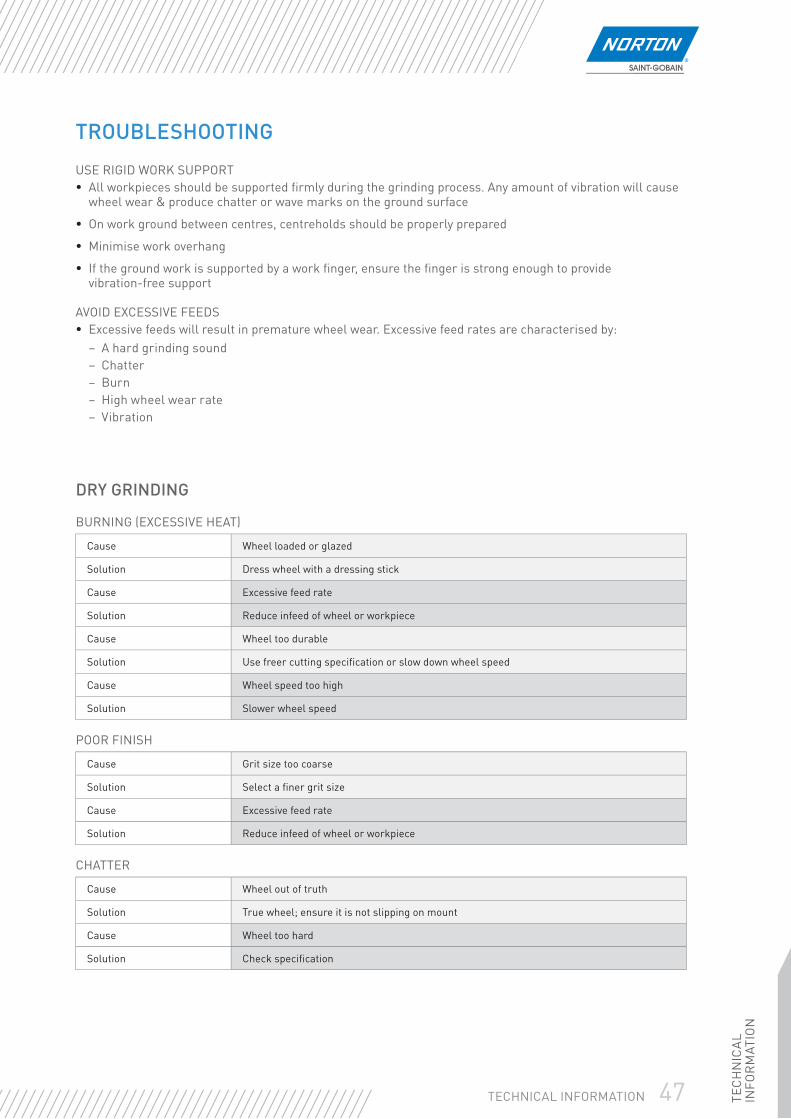
TEC
HN
ICA
L IN
FOR
MAT
ION
47TECHNICAL INFORMATION
TROUBLESHOOTING
USE RIGID WORK SUPPORT• All workpieces should be supported fi rmly during the grinding process. Any amount of vibration will cause
wheel wear & produce chatter or wave marks on the ground surface
• On work ground between centres, centreholds should be properly prepared
• Minimise work overhang
• If the ground work is supported by a work fi nger, ensure the fi nger is strong enough to provide vibration-free support
AVOID EXCESSIVE FEEDS• Excessive feeds will result in premature wheel wear. Excessive feed rates are characterised by:
– A hard grinding sound– Chatter– Burn– High wheel wear rate– Vibration
DRY GRINDING
BURNING (EXCESSIVE HEAT)
Cause Wheel loaded or glazed
Solution Dress wheel with a dressing stick
Cause Excessive feed rate
Solution Reduce infeed of wheel or workpiece
Cause Wheel too durable
Solution Use freer cutting specifi cation or slow down wheel speed
Cause Wheel speed too high
Solution Slower wheel speed
POOR FINISH
Cause Grit size too coarse
Solution Select a fi ner grit size
Cause Excessive feed rate
Solution Reduce infeed of wheel or workpiece
CHATTER
Cause Wheel out of truth
Solution True wheel; ensure it is not slipping on mount
Cause Wheel too hard
Solution Check specifi cation
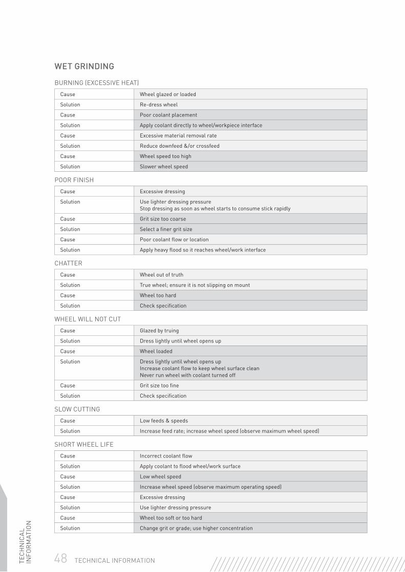
48 TECHNICAL INFORMATIONTEC
HN
ICA
L IN
FOR
MAT
ION
WET GRINDING
BURNING (EXCESSIVE HEAT)
Cause Wheel glazed or loaded
Solution Re-dress wheel
Cause Poor coolant placement
Solution Apply coolant directly to wheel/workpiece interface
Cause Excessive material removal rate
Solution Reduce downfeed &/or crossfeed
Cause Wheel speed too high
Solution Slower wheel speed
POOR FINISH
Cause Excessive dressing
Solution Use lighter dressing pressureStop dressing as soon as wheel starts to consume stick rapidly
Cause Grit size too coarse
Solution Select a fi ner grit size
Cause Poor coolant fl ow or location
Solution Apply heavy fl ood so it reaches wheel/work interface
CHATTER
Cause Wheel out of truth
Solution True wheel; ensure it is not slipping on mount
Cause Wheel too hard
Solution Check specifi cation
WHEEL WILL NOT CUT
Cause Glazed by truing
Solution Dress lightly until wheel opens up
Cause Wheel loaded
Solution Dress lightly until wheel opens upIncrease coolant fl ow to keep wheel surface cleanNever run wheel with coolant turned off
Cause Grit size too fi ne
Solution Check specifi cation
SLOW CUTTING
Cause Low feeds & speeds
Solution Increase feed rate; increase wheel speed (observe maximum wheel speed)
SHORT WHEEL LIFE
Cause Incorrect coolant fl ow
Solution Apply coolant to fl ood wheel/work surface
Cause Low wheel speed
Solution Increase wheel speed (observe maximum operating speed)
Cause Excessive dressing
Solution Use lighter dressing pressure
Cause Wheel too soft or too hard
Solution Change grit or grade; use higher concentration

TEC
HN
ICA
L IN
FOR
MAT
ION
49TECHNICAL INFORMATION
DIAMOND BLADES
PERSONAL PROTECTIONSafety goggles, ear defenders, safety gloves, dust masks and, if conditions are severe, additional face protection. Leather aprons and safety shoes must be worn.
TECHNICAL INFORMATIONOPERATING SPEEDS
MAXIMUM OPERATING SPEED
DIAMETER(mm) MAX M/S MAX RPM
100 80 15300
115 80 13300
125 80 12250
150 80 10200
180 80 8500
200 80 7650
230 80 6650
250 80 6100
300 100 6400
350 100 5500
400 100 4800
450 63 2700
Never exceed the Maximum Operating Speeds:
• Hand held blades ø 230mm: 80m/s• Hand held blades ø > 230mm: 100m/s• Others: 63m/s
MouthProtection
WearGloves
EyeProtection
EarProtection
ReadInstructions
Not forSide
Grinding
DryCutting
WetCutting
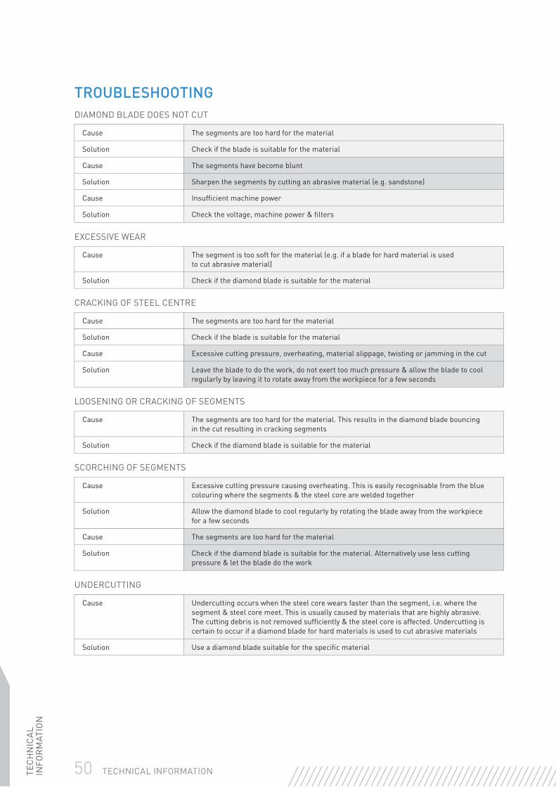
50 TECHNICAL INFORMATIONTEC
HN
ICA
L IN
FOR
MAT
ION
TROUBLESHOOTINGDIAMOND BLADE DOES NOT CUT
Cause The segments are too hard for the material
Solution Check if the blade is suitable for the material
Cause The segments have become blunt
Solution Sharpen the segments by cutting an abrasive material (e.g. sandstone)
Cause Insuffi cient machine power
Solution Check the voltage, machine power & fi lters
EXCESSIVE WEAR
Cause The segment is too soft for the material (e.g. if a blade for hard material is used to cut abrasive material)
Solution Check if the diamond blade is suitable for the material
CRACKING OF STEEL CENTRE
Cause The segments are too hard for the material
Solution Check if the blade is suitable for the material
Cause Excessive cutting pressure, overheating, material slippage, twisting or jamming in the cut
Solution Leave the blade to do the work, do not exert too much pressure & allow the blade to cool regularly by leaving it to rotate away from the workpiece for a few seconds
LOOSENING OR CRACKING OF SEGMENTS
Cause The segments are too hard for the material. This results in the diamond blade bouncing in the cut resulting in cracking segments
Solution Check if the diamond blade is suitable for the material
SCORCHING OF SEGMENTS
Cause Excessive cutting pressure causing overheating. This is easily recognisable from the blue colouring where the segments & the steel core are welded together
Solution Allow the diamond blade to cool regularly by rotating the blade away from the workpiece for a few seconds
Cause The segments are too hard for the material
Solution Check if the diamond blade is suitable for the material. Alternatively use less cutting pressure & let the blade do the work
UNDERCUTTING
Cause Undercutting occurs when the steel core wears faster than the segment, i.e. where the segment & steel core meet. This is usually caused by materials that are highly abrasive. The cutting debris is not removed suffi ciently & the steel core is affected. Undercutting is certain to occur if a diamond blade for hard materials is used to cut abrasive materials
Solution Use a diamond blade suitable for the specifi c material
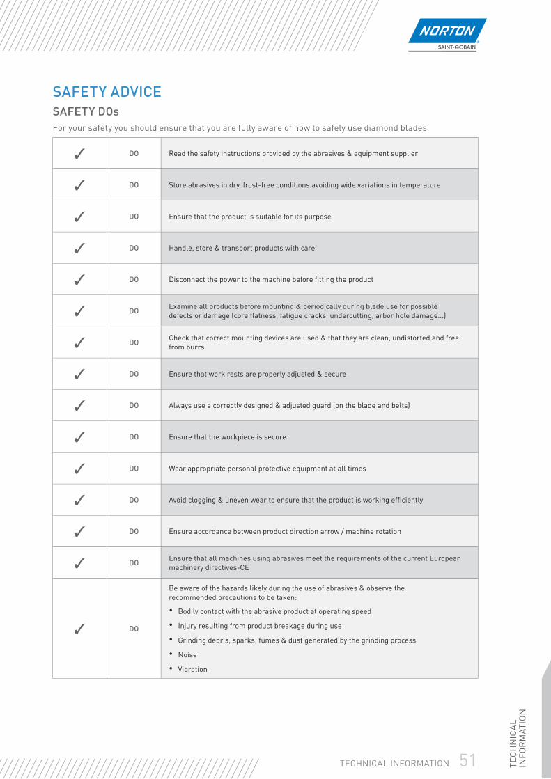
TEC
HN
ICA
L IN
FOR
MAT
ION
51TECHNICAL INFORMATION
SAFETY ADVICESAFETY DOsFor your safety you should ensure that you are fully aware of how to safely use diamond blades
✓ DO Read the safety instructions provided by the abrasives & equipment supplier
✓ DO Store abrasives in dry, frost-free conditions avoiding wide variations in temperature
✓ DO Ensure that the product is suitable for its purpose
✓ DO Handle, store & transport products with care
✓ DO Disconnect the power to the machine before fi tting the product
✓ DO Examine all products before mounting & periodically during blade use for possible defects or damage (core fl atness, fatigue cracks, undercutting, arbor hole damage...)
✓ DO Check that correct mounting devices are used & that they are clean, undistorted and free from burrs
✓ DO Ensure that work rests are properly adjusted & secure
✓ DO Always use a correctly designed & adjusted guard (on the blade and belts)
✓ DO Ensure that the workpiece is secure
✓ DO Wear appropriate personal protective equipment at all times
✓ DO Avoid clogging & uneven wear to ensure that the product is working effi ciently
✓ DO Ensure accordance between product direction arrow / machine rotation
✓ DO Ensure that all machines using abrasives meet the requirements of the current European machinery directives-CE
✓ DO
Be aware of the hazards likely during the use of abrasives & observe the recommended precautions to be taken:
• Bodily contact with the abrasive product at operating speed
• Injury resulting from product breakage during use
• Grinding debris, sparks, fumes & dust generated by the grinding process
• Noise
• Vibration
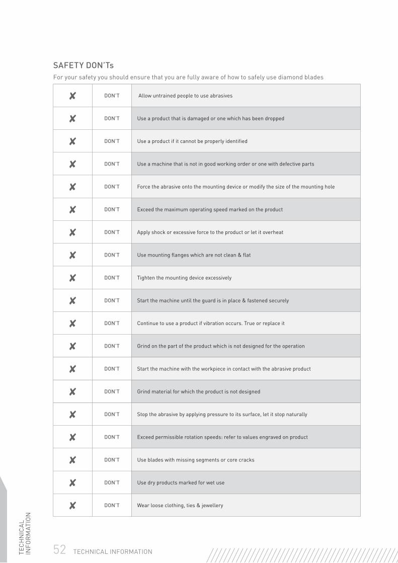
52 TECHNICAL INFORMATIONTEC
HN
ICA
L IN
FOR
MAT
ION
SAFETY DON’TsFor your safety you should ensure that you are fully aware of how to safely use diamond blades
✘ DON’T Allow untrained people to use abrasives
✘ DON’T Use a product that is damaged or one which has been dropped
✘ DON’T Use a product if it cannot be properly identifi ed
✘ DON’T Use a machine that is not in good working order or one with defective parts
✘ DON’T Force the abrasive onto the mounting device or modify the size of the mounting hole
✘ DON’T Exceed the maximum operating speed marked on the product
✘ DON’T Apply shock or excessive force to the product or let it overheat
✘ DON’T Use mounting fl anges which are not clean & fl at
✘ DON’T Tighten the mounting device excessively
✘ DON’T Start the machine until the guard is in place & fastened securely
✘ DON’T Continue to use a product if vibration occurs. True or replace it
✘ DON’T Grind on the part of the product which is not designed for the operation
✘ DON’T Start the machine with the workpiece in contact with the abrasive product
✘ DON’T Grind material for which the product is not designed
✘ DON’T Stop the abrasive by applying pressure to its surface, let it stop naturally
✘ DON’T Exceed permissible rotation speeds: refer to values engraved on product
✘ DON’T Use blades with missing segments or core cracks
✘ DON’T Use dry products marked for wet use
✘ DON’T Wear loose clothing, ties & jewellery

TEC
HN
ICA
L IN
FOR
MAT
ION
53TECHNICAL INFORMATION
NOTES

54 TECHNICAL INFORMATIONTEC
HN
ICA
L IN
FOR
MAT
ION
NOTES