Embed Size (px)
Citation preview
GETTING STARTED GUIDE
NI 920816-Channel, ±20 mA, 24-Bit Analog Input Module
This document explains how to connect to the NI 9208. In thisdocument, the NI 9208 with spring terminal and the NI 9208 withDSUB are referred to inclusively as the NI 9208.
Note Before you begin, complete the software andhardware installation procedures in your chassisdocumentation.
Note The guidelines in this document are specific tothe NI 9208. The other components in the system mightnot meet the same safety ratings. Refer to thedocumentation for each component in the system todetermine the safety and EMC ratings for the entiresystem.
Safety GuidelinesOperate the NI 9208 only as described in this document.
Caution Do not operate the NI 9208 in a manner notspecified in this document. Product misuse can result ina hazard. You can compromise the safety protectionbuilt into the product if the product is damaged in any
2 | ni.com | NI 9208 Getting Started Guide
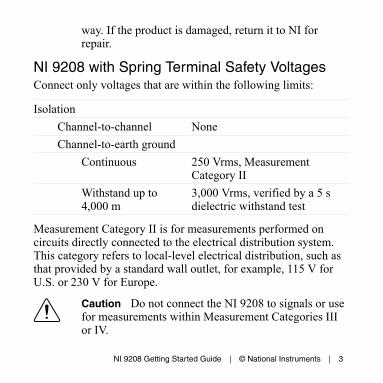
way. If the product is damaged, return it to NI forrepair.
NI 9208 with Spring Terminal Safety VoltagesConnect only voltages that are within the following limits:
IsolationChannel-to-channel NoneChannel-to-earth ground
Continuous 250 Vrms, MeasurementCategory II
Withstand up to4,000 m
3,000 Vrms, verified by a 5 sdielectric withstand test
Measurement Category II is for measurements performed oncircuits directly connected to the electrical distribution system.This category refers to local-level electrical distribution, such asthat provided by a standard wall outlet, for example, 115 V forU.S. or 230 V for Europe.
Caution Do not connect the NI 9208 to signals or usefor measurements within Measurement Categories IIIor IV.
NI 9208 Getting Started Guide | © National Instruments | 3
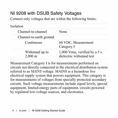
NI 9208 with DSUB Safety VoltagesConnect only voltages that are within the following limits:
IsolationChannel-to-channel NoneChannel-to-earth ground
Continuous 60 VDC, MeasurementCategory I
Withstand up to2,000 m
1,000 Vrms, verified by a 5 sdielectric withstand test
Measurement Category I is for measurements performed oncircuits not directly connected to the electrical distribution systemreferred to as MAINS voltage. MAINS is a hazardous liveelectrical supply system that powers equipment. This category isfor measurements of voltages from specially protected secondarycircuits. Such voltage measurements include signal levels, specialequipment, limited-energy parts of equipment, circuits poweredby regulated low-voltage sources, and electronics.
4 | ni.com | NI 9208 Getting Started Guide
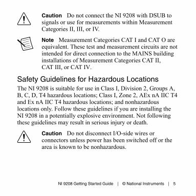
Caution Do not connect the NI 9208 with DSUB tosignals or use for measurements within MeasurementCategories II, III, or IV.
Note Measurement Categories CAT I and CAT O areequivalent. These test and measurement circuits are notintended for direct connection to the MAINS buildinginstallations of Measurement Categories CAT II,CAT III, or CAT IV.
Safety Guidelines for Hazardous LocationsThe NI 9208 is suitable for use in Class I, Division 2, Groups A,B, C, D, T4 hazardous locations; Class I, Zone 2, AEx nA IIC T4and Ex nA IIC T4 hazardous locations; and nonhazardouslocations only. Follow these guidelines if you are installing theNI 9208 in a potentially explosive environment. Not followingthese guidelines may result in serious injury or death.
Caution Do not disconnect I/O-side wires orconnectors unless power has been switched off or thearea is known to be nonhazardous.
NI 9208 Getting Started Guide | © National Instruments | 5
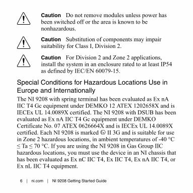
Caution Do not remove modules unless power hasbeen switched off or the area is known to benonhazardous.
Caution Substitution of components may impairsuitability for Class I, Division 2.
Caution For Division 2 and Zone 2 applications,install the system in an enclosure rated to at least IP54as defined by IEC/EN 60079-15.
Special Conditions for Hazardous Locations Use inEurope and InternationallyThe NI 9208 with spring terminal has been evaluated as Ex nAIIC T4 Gc equipment under DEMKO 12 ATEX 1202658X and isIECEx UL 14.0089X certified. The NI 9208 with DSUB has beenevaluated as Ex nA IIC T4 Gc equipment under DEMKOCertificate No. 07 ATEX 0626664X and is IECEx UL 14.0089Xcertified. Each NI 9208 is marked II 3G and is suitable for usein Zone 2 hazardous locations, in ambient temperatures of -40 °C≤ Ta ≤ 70 °C. If you are using the NI 9208 in Gas Group IIChazardous locations, you must use the device in an NI chassis thathas been evaluated as Ex nC IIC T4, Ex IIC T4, Ex nA IIC T4, orEx nL IIC T4 equipment.
6 | ni.com | NI 9208 Getting Started Guide
Caution You must make sure that transientdisturbances do not exceed 140% of the rated voltage.
Caution The system shall only be used in an area ofnot more than Pollution Degree 2, as defined inIEC/EN 60664-1.
Caution The system shall be mounted in anATEX/IECEx-certified enclosure with a minimumingress protection rating of at least IP54 as defined inIEC/EN 60079-15.
Caution The enclosure must have a door or coveraccessible only by the use of a tool.
Electromagnetic Compatibility GuidelinesThis product was tested and complies with the regulatoryrequirements and limits for electromagnetic compatibility (EMC)stated in the product specifications. These requirements andlimits provide reasonable protection against harmful interferencewhen the product is operated in the intended operationalelectromagnetic environment.
NI 9208 Getting Started Guide | © National Instruments | 7
This product is intended for use in industrial locations. However,harmful interference may occur in some installations, when theproduct is connected to a peripheral device or test object, or if theproduct is used in residential or commercial areas. To minimizeinterference with radio and television reception and preventunacceptable performance degradation, install and use thisproduct in strict accordance with the instructions in the productdocumentation.
Furthermore, any changes or modifications to the product notexpressly approved by National Instruments could void yourauthority to operate it under your local regulatory rules.
Caution To ensure the specified EMC performance,operate the NI 9208 with DSUB only with shieldedcables and accessories. Do not use unshielded cables oraccessories unless they are installed in a shieldedenclosure with properly designed and shielded input/output ports and connected to the product using ashielded cable. If unshielded cables or accessories arenot properly installed and shielded, the EMCspecifications for the product are no longer guaranteed.
8 | ni.com | NI 9208 Getting Started Guide
Special Conditions for Marine ApplicationsSome products are Lloyd’s Register (LR) Type Approved formarine (shipboard) applications. To verify Lloyd’s Registercertification for a product, visit ni.com/certification and searchfor the LR certificate, or look for the Lloyd’s Register mark onthe product.
Caution In order to meet the EMC requirements formarine applications, install the product in a shieldedenclosure with shielded and/or filtered power andinput/output ports. In addition, take precautions whendesigning, selecting, and installing measurement probesand cables to ensure that the desired EMC performanceis attained.
NI 9208 Getting Started Guide | © National Instruments | 9
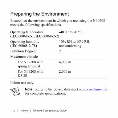
Preparing the EnvironmentEnsure that the environment in which you are using the NI 9208meets the following specifications.
Operating temperature(IEC 60068-2-1, IEC 60068-2-2)
-40 °C to 70 °C
Operating humidity(IEC 60068-2-78)
10% RH to 90% RH,noncondensing
Pollution Degree 2Maximum altitude
For NI 9208 withspring terminal
4,000 m
For NI 9208 withDSUB
2,000 m
Indoor use only.
Note Refer to the device datasheet on ni.com/manualsfor complete specifications.
10 | ni.com | NI 9208 Getting Started Guide
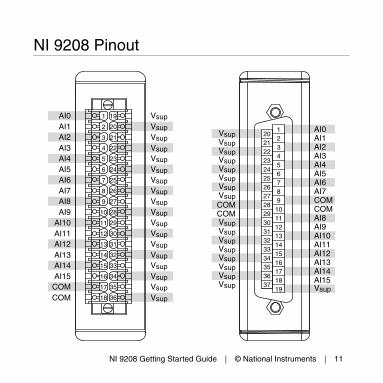
NI 9208 Pinout
VsupVsupVsupVsupVsupVsupVsupVsupCOMCOMVsupVsupVsupVsupVsupVsupVsupVsup
AI0AI1AI2AI3AI4AI5AI6AI7COMCOMAI8AI9AI10AI11AI12AI13AI14AI15Vsup
123456789
10111213141516171819
202122232425262728293031323334353637COM
AI14
AI12
AI10
AI8
AI6
AI4
AI2
AI0
COM
AI15
AI13
AI11
AI9
AI7
AI5
AI3
AI1
Vsup
Vsup
Vsup
Vsup
Vsup
Vsup
Vsup
Vsup
Vsup
Vsup
Vsup
Vsup
Vsup
Vsup
Vsup
Vsup
Vsup
Vsup
1
2
3
4
5
6
7
8
9
10
11
12
13
14
15
16
17
18
19
20
21
22
23
24
25
26
27
28
29
30
31
32
33
34
35
36
NI 9208 Getting Started Guide | © National Instruments | 11
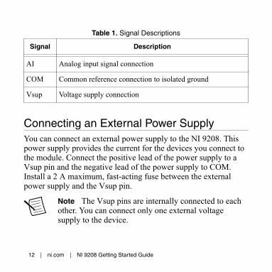
Table 1. Signal Descriptions
Signal Description
AI Analog input signal connection
COM Common reference connection to isolated ground
Vsup Voltage supply connection
Connecting an External Power SupplyYou can connect an external power supply to the NI 9208. Thispower supply provides the current for the devices you connect tothe module. Connect the positive lead of the power supply to aVsup pin and the negative lead of the power supply to COM.Install a 2 A maximum, fast-acting fuse between the externalpower supply and the Vsup pin.
Note The Vsup pins are internally connected to eachother. You can connect only one external voltagesupply to the device.
12 | ni.com | NI 9208 Getting Started Guide
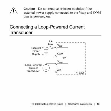
Caution Do not remove or insert modules if theexternal power supply connected to the Vsup and COMpins is powered on.
Connecting a Loop-Powered CurrentTransducer
NI 9208
+
–
AI0
ExternalPowerSupply
Loop-PoweredCurrent
Transducer
Vsup
COM
Vsup
2 AMax
NI 9208 Getting Started Guide | © National Instruments | 13
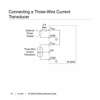
Connecting a Three-Wire CurrentTransducer
NI 9208
Vsup
COM
+
–
COM
Vsup
AI0
ExternalPowerSupply
Three-WireCurrent
Transducer
2 AMax
OUT
+
–
14 | ni.com | NI 9208 Getting Started Guide
NI 9208 Connection Guidelines• Make sure that devices you connect to the NI 9208 are
compatible with the module specifications.• You must use 2-wire ferrules to create a secure connection
when connecting more than one wire to a single terminal onthe NI 9208 with spring terminal.
• Push the wire into the terminal when using a solid wire or astranded wire with a ferrule.
• Open the terminal by pressing the push button when usingstranded wire without a ferrule.
High-Vibration Application ConnectionsIf your application is subject to high vibration, NI recommendsthat you use the NI 9940 backshell kit to protect connections tothe NI 9208 with spring terminal.
Overvoltage ProtectionThe NI 9208 provides overvoltage protection for each channel.
Note Refer to the device datasheet on ni.com/manualsfor more information about overvoltage protection.
NI 9208 Getting Started Guide | © National Instruments | 15
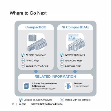
Where to Go Next
CompactRIO NI CompactDAQ
Located at ni.com/manuals
RELATED INFORMATION
C Series Documentation& Resourcesni.com/info cseriesdoc
Servicesni.com/services
Installs with the software
NI 9208 Datasheet
NI-RIO Help
LabVIEW FPGA Help
NI 9208 Datasheet
NI-DAQmx Help
LabVIEW Help
16 | ni.com | NI 9208 Getting Started Guide
Worldwide Support and ServicesThe NI website is your complete resource for technical support.At ni.com/support, you have access to everything fromtroubleshooting and application development self-help resourcesto email and phone assistance from NI Application Engineers.
Visit ni.com/services for NI Factory Installation Services, repairs,extended warranty, and other services.
Visit ni.com/register to register your NI product. Productregistration facilitates technical support and ensures that youreceive important information updates from NI.
A Declaration of Conformity (DoC) is our claim of compliancewith the Council of the European Communities using themanufacturer’s declaration of conformity. This system affords theuser protection for electromagnetic compatibility (EMC) andproduct safety. You can obtain the DoC for your product byvisiting ni.com/certification. If your product supports calibration,you can obtain the calibration certificate for your product at ni.com/calibration.
NI 9208 Getting Started Guide | © National Instruments | 17
NI corporate headquarters is located at11500 North Mopac Expressway, Austin, Texas, 78759-3504. NIalso has offices located around the world. For telephone supportin the United States, create your service request at ni.com/supportor dial 1 866 ASK MYNI (275 6964). For telephone supportoutside the United States, visit the Worldwide Offices section of ni.com/niglobal to access the branch office websites, whichprovide up-to-date contact information, support phone numbers,email addresses, and current events.
Refer to the NI Trademarks and Logo Guidelines at ni.com/trademarks for information on NItrademarks. Other product and company names mentioned herein are trademarks or trade namesof their respective companies. For patents covering NI products/technology, refer to theappropriate location: Help»Patents in your software, the patents.txt file on your media, or theNational Instruments Patent Notice at ni.com/patents. You can find information about end-userlicense agreements (EULAs) and third-party legal notices in the readme file for your NI product.Refer to the Export Compliance Information at ni.com/legal/export-compliance for the NIglobal trade compliance policy and how to obtain relevant HTS codes, ECCNs, and other import/export data. NI MAKES NO EXPRESS OR IMPLIED WARRANTIES AS TO THE ACCURACY OFTHE INFORMATION CONTAINED HEREIN AND SHALL NOT BE LIABLE FOR ANY ERRORS.U.S. Government Customers: The data contained in this manual was developed at privateexpense and is subject to the applicable limited rights and restricted data rights as set forth in FAR52.227-14, DFAR 252.227-7014, and DFAR 252.227-7015.
© 2009—2016 National Instruments. All rights reserved.
375170C-01 Sep16