Embed Size (px)
Citation preview
8/6/2019 Nhrp 15 1mt Book
http://slidepdf.com/reader/full/nhrp-15-1mt-book 1/51
IP Addressing: NHRP ConfigurationGuide, Cisco IOS Release 15.1MT
Americas HeadquartersCisco Systems, Inc.
170 West Tasman Drive
San Jose, CA 95134-1706
USA
http://www.cisco.com
Tel: 408 526-4000
800 553-NETS (6387)
Fax: 408 527-0883
8/6/2019 Nhrp 15 1mt Book
http://slidepdf.com/reader/full/nhrp-15-1mt-book 2/51
CON T EN T S
Configuring NHRP 1
Finding Feature Information 1
Information About NHRP 1
How NHRP and NBMA Networks Interact 2
Dynamically Built Hub-and-Spoke Networks 2
Next Hop Server Selection 3
NHRP Registration 4
NHRP Used with a DMVPN 5
Dynamic Spoke-to-Spoke Tunnels 5
Developmental Phases of DMVPN and NHRP 6
Phase 2 7
Phase3 7
Spoke Refresh Mechanism f or Spoke-to-Spoke Tunnels 8
Process Switching 8
CEF Switching 8
How to Configure NHRP 9Configuring a GRE Tunnel f or Multipoint Operation 9
Enabling NHRP on an Interf ace 10
Configuring a Static IP-to-NBMA Address Mapping on a Station 12
Statically Configuring a Next Hop Server 13
Changing the Length of Time NBMA Addresses Are Advertised as Valid 14
Specifying the NHRP Authentication String 15
Configuring NHRP Server-Only Mode 17
Controlling the Triggering of NHRP 18
Triggering NHRP on a per-Destination Basis 18
Triggering NHRP on a Packet Count Basis 19
Triggering NHRP Based on Traffic Thresholds 20
Changing the Rate for Triggering SVCs 21
Changing the Sampling Time Period and Sampling Rate 22
Applying the Triggering and Teardown Rates to Specific Destinations 23
Controlling the NHRP Packet Rate 24
IP Addressing: NHRP Configuration Guide, Cisco IOS Release 15.1MTii
8/6/2019 Nhrp 15 1mt Book
http://slidepdf.com/reader/full/nhrp-15-1mt-book 3/51
Suppressing Forward and Reverse Record Options 26
Specifying the NHRP Responder IP Address 27
Clearing the NHRP Cache 28
Configuration Examples for NHRP 28Physical Network Designs for Logical NBMA Examples 28
Applying NHRP Rates to Specific Destinations Example 30
NHRP on a Multipoint Tunnel Example 31
Show NHRP Examples 32
Additional References 34
Feature Information for Configuring NHRP 35
Shortcut Switching Enhancements for NHRP in DMVPN Networks 37
Finding Feature Information 37
Restrictions for Shortcut Switching Enhancements for NHRP 37
Information About Shortcut Switching Enhancements for NHRP 38
NHRP in DMVPN Networks Overview 38
Benefits of NHRP Shortcut Switching Enhancements 39
NHRP Mapping and Adjacency Override 40
NHRP Purge Request Reply 42
How to Configure Shortcut Switching for NHRP 42
Enabling NHRP Shortcut Switching on an Interface 42
Configuring NHRP Redirect 43
Configuration Examples for Shortcut Switching Enhancements for NHRP 45
Configuring NHRP Shortcut Switching and NHRP Redirect Example 45
Additional References 45
Feature Information for Shortcut Switching Enhancements for NHRP in DMVPN Networks 46
Contents
IP Addressing: NHRP Configuration Guide, Cisco IOS Release 15.1MTiii
8/6/2019 Nhrp 15 1mt Book
http://slidepdf.com/reader/full/nhrp-15-1mt-book 4/51
Configuring NHRP
The Next Hop Resolution Protocol (NHRP) is an Address Resolution Protocol (ARP)-like protocol that
dynamically maps a nonbroadcast multiaccess (NBMA) network. With NHRP, systems attached to an
NBMA network can dynamically learn the NBMA (physical) address of the other systems that are part of
that network, allowing these systems to directly communicate.
NHRP is a client and server protocol where the hub is the Next Hop Server (NHS) and the spokes are theNext Hop Clients (NHCs). The hub maintains an NHRP database of the public interface addresses of each
spoke. Each spoke registers its real address when it boots and queries the NHRP database for real
addresses of the destination spokes to build direct tunnels.
• Finding Feature Information, page 1
• Information About NHRP, page 1
• How to Configure NHRP, page 9
• Configuration Examples for NHRP, page 28
• Additional References, page 34
• Feature Information for Configuring NHRP, page 35
Finding Feature InformationYour software release may not support all the features documented in this module. For the latest feature
information and caveats, see the release notes for your platform and software release. To find information
about the features documented in this module, and to see a list of the releases in which each feature is
supported, see the Feature Information Table at the end of this document.
Use Cisco Feature Navigator to find information about platform support and Cisco software image support.
To access Cisco Feature Navigator, go to www.cisco.com/go/cfn. An account on Cisco.com is not required
Information About NHRP• How NHRP and NBMA Networks Interact, page 2
• Dynamically Built Hub-and-Spoke Networks, page 2
• Dynamic Spoke-to-Spoke Tunnels, page 5
• Spoke Refresh Mechanism for Spoke-to-Spoke Tunnels, page 8
IP Addressing: NHRP Configuration Guide, Cisco IOS Release 15.1MT1
8/6/2019 Nhrp 15 1mt Book
http://slidepdf.com/reader/full/nhrp-15-1mt-book 5/51
How NHRP and NBMA Networks InteractMost WAN networks are a collection of point-to-point links. Virtual tunnel networks (for example Generic
Routing Encapsulation (GRE) tunnels) are also a collection of point-to-point links. To effectively scale the
connectivity of these point-to-point links, they are usually grouped into a single or multilayer hub-and-spoke network. Multipoint interfaces (for example, GRE tunnel interfaces) can be used to reduce the
configuration on a hub router in such a network. This resulting network is a NBMA network.
Because there are multiple tunnel endpoints reachable through the single multipoint interface, there needs
to be a mapping from the logical tunnel endpoint IP address to the physical tunnel endpoint IP address in
order to forward packets out the multipoint GRE (mGRE) tunnel interfaces over this NBMA network. This
mapping could be statically configured, but it is preferable if the mapping can be discovered or learned
dynamically.
NHRP is an ARP-like protocol that alleviates these NBMA network problems. With NHRP, systems
attached to an NBMA network dynamically learn the NBMA address of the other systems that are part of
that network, allowing these systems to directly communicate without requiring traffic to use an
intermediate hop.
Routers, access servers, and hosts can use NHRP to discover the addresses of other routers and hostsconnected to an NBMA network. Partially meshed NBMA networks typically have multiple logical
networks behind the NBMA network. In such configurations, packets traversing the NBMA network might
have to make several hops over the NBMA network before arriving at the exit router (the router nearest the
destination network). When NHRP is combined with IPsec, the NBMA network is basically a collection of
point-to-point logical tunnel links over a physical IP network.
NHRP allows two functions to help support these NBMA networks:
1 NHRP Registration. NHRP allows Next Hop Clients (NHCs) to dynamically register with Next Hop
Servers (NHSs). This registration function allows the NHCs to join the NBMA network without
configuration changes on the NHSs, especially in cases where the NHC has a dynamic physical IP
address or is behind a Network Address Translation (NAT) router that dynamically changes the
physical IP address. In these cases, it would be impossible to preconfigure the logical virtual private
network (VPN IP) to physical (NBMA IP) mapping for the NHC on the NHS. See the "NHRPRegistration" for more information.
2 NHRP Resolution. NHRP allows one NHC (spoke) to dynamically discover the logical VPN IP to
physical NBMA IP mapping for another NHC (spoke) within the same NBMA network. Without this
discovery, IP packets traversing from hosts behind one spoke to hosts behind another spoke would have
to traverse by way of the NHS (hub) router. This process would increase the utilization of the hub’s
physical bandwidth and CPU to process these packets that enter and exit the hub on the multipoint
interface. With NHRP, systems attached to an NBMA network dynamically learn the NBMA address of
the other systems that are part of that network, allowing these systems to directly communicate without
requiring traffic to use an intermediate hop. This function alleviates the load on the intermediate hop
(NHS) and can increase the overall bandwidth of the NBMA network to be greater than the bandwidth
of the hub router.
Dynamically Built Hub-and-Spoke NetworksWith NHRP, the NBMA network is initially laid out as a hub-and-spoke network that can be multiple
hierarchical layers of NHCs as spokes and NHSs as hubs. The NHCs are configured with static mapping
information to reach their NHSs and will connect to their NHS and send an NHRP registration to the NHS.
This configuration allows the NHS to dynamically learn the mapping information for the spoke, reducing
the configuration needed on the hub and allowing the spoke to obtain a dynamic NBMA (physical) IP
address.
How NHRP and NBMA Networks Interact
Information About NHRP
IP Addressing: NHRP Configuration Guide, Cisco IOS Release 15.1MT
2
8/6/2019 Nhrp 15 1mt Book
http://slidepdf.com/reader/full/nhrp-15-1mt-book 6/51
Once the base hub-and-spoke network is dynamically built, NHRP resolution requests and responses can be
used to dynamically discover spoke-to-spoke mapping information, which allows spokes to bypass the hub
and contact each other directly. This process allows a dynamic mesh of connections between spokes to be
built based on data traffic patterns without requiring a preconfigured static fully meshed network. Using a
dynamic-mesh network allows smaller spoke routers to participate up to their capability in a large NBMA
network when these smaller spoke routers do not have the resources to participate in a full mesh on thesame size network. The smaller spoke routers do not need to build out all possible spoke-to-spoke links;
these routers need to build only the ones they are currently using.
• Next Hop Server Selection, page 3
• NHRP Registration, page 4
• NHRP Used with a DMVPN, page 5
Next Hop Server Selection
NHRP resolution requests traverse one or more hops (hubs) within the base hub-and-spoke NBMA
subnetwork before reaching the station that is expected to generate a response. Each station (including the
source station) chooses a neighboring NHS to which it forwards the request. The NHS selection procedure
typically involves performing a routing decision based upon the network layer destination address of the
NHRP request. The NHRP resolution request eventually arrives at a station that generates an NHRP
resolution reply. This responding station either serves the destination, or is the destination itself. The
responding station generates a reply using the source address from within the NHRP packet to determine
where the reply should be sent.
The Cisco implementation of NHRP also supports and extends the IEEE RFC 2332, NBMA Next Hop
Resolution Protocol (NHRP) .
The Cisco implementation of NHRP supports IP Version 4 at the network layer and at the link layer with
multipoint GRE, Ethernet, Switched Multimegabit Data Service (SMDS), Frame Relay, and ATM.
Although NHRP is available on Ethernet, NHRP need not be implemented over Ethernet media because
Ethernet is capable of broadcasting and the standard Ethernet IP ARP protocol is sufficient.
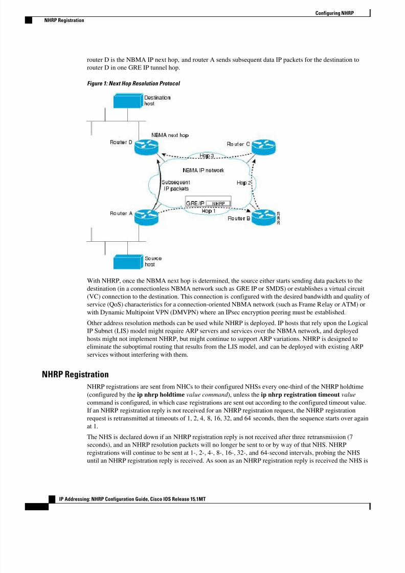
The figure below illustrates four routers connected to an NBMA network. Within the network are IP routersnecessary for the routers to communicate with each other by tunneling the IP data packets in GRE IP tunnel
packets. The infrastructure layer routers support logical IP tunnel circuit connections represented by hops 1
2, and 3. When router A attempts to forward an IP packet from the source host to the destination host,
NHRP is triggered. On behalf of the source host, router A sends an NHRP resolution request packet
encapsulated in a GRE IP packet, which takes three hops across the network to reach router D, connected to
the destination host. After router A receives a positive NHRP resolution reply, router A determines that
Configuring NHRP
Next Hop Server Selection
IP Addressing: NHRP Configuration Guide, Cisco IOS Release 15.1MT3
8/6/2019 Nhrp 15 1mt Book
http://slidepdf.com/reader/full/nhrp-15-1mt-book 7/51
router D is the NBMA IP next hop, and router A sends subsequent data IP packets for the destination to
router D in one GRE IP tunnel hop.
Figure 1: Next Hop Resolution Protocol
With NHRP, once the NBMA next hop is determined, the source either starts sending data packets to the
destination (in a connectionless NBMA network such as GRE IP or SMDS) or establishes a virtual circuit
(VC) connection to the destination. This connection is configured with the desired bandwidth and quality of
service (QoS) characteristics for a connection-oriented NBMA network (such as Frame Relay or ATM) or
with Dynamic Multipoint VPN (DMVPN) where an IPsec encryption peering must be established.
Other address resolution methods can be used while NHRP is deployed. IP hosts that rely upon the Logical
IP Subnet (LIS) model might require ARP servers and services over the NBMA network, and deployed
hosts might not implement NHRP, but might continue to support ARP variations. NHRP is designed to
eliminate the suboptimal routing that results from the LIS model, and can be deployed with existing ARP
services without interfering with them.
NHRP Registration
NHRP registrations are sent from NHCs to their configured NHSs every one-third of the NHRP holdtime
(configured by the ip nhrp holdtime value command ), unless the ip nhrp registration timeout value
command is configured, in which case registrations are sent out according to the configured timeout value.If an NHRP registration reply is not received for an NHRP registration request, the NHRP registration
request is retransmitted at timeouts of 1, 2, 4, 8, 16, 32, and 64 seconds, then the sequence starts over again
at 1.
The NHS is declared down if an NHRP registration reply is not received after three retransmission (7
seconds), and an NHRP resolution packets will no longer be sent to or by way of that NHS. NHRP
registrations will continue to be sent at 1-, 2-, 4-, 8-, 16-, 32-, and 64-second intervals, probing the NHS
until an NHRP registration reply is received. As soon as an NHRP registration reply is received the NHS is
Configuring NHRP
NHRP Registration
IP Addressing: NHRP Configuration Guide, Cisco IOS Release 15.1MT
4
8/6/2019 Nhrp 15 1mt Book
http://slidepdf.com/reader/full/nhrp-15-1mt-book 8/51
immediately declared up, the NHRP registration requests revert to being sent every one-third of NHRP
holdtime or the value configured in the ip nhrp registration timeoutcommand, and the NHS can again be
sent NHRP resolution requests. The show ip nhrp nhs detail command can be used to check the state of
the NHRP NHSs.
NHRP Used with a DMVPN
NHRP can be used to help build a VPN. In this context, a VPN consists of a virtual Layer 3 network that is
built on top of an actual Layer 3 network. The topology you use over the VPN is largely independent of the
underlying network, and the protocols you run over it are completely independent of it. The Dynamic
Multipoint VPN (DMVPN) is based on GRE IP logical tunnels that can be protected by adding in IPsec to
encrypt the GRE IP tunnels.
All routers running Cisco IOS Release 10.3 or later releases can implement NHRP and, thus, can act as
NHSs or NHCs. To obtain the base functionality of DMVPN (GRE IP+IPsec), which uses NHRP, you mus
run Cisco IOS Release 12.3(9), 12.3(8)T, or a later release.
Note For the latest extensions and enhancements to NHRP, you must use Cisco IOS Release 12.4 or Cisco IOSRelease 12.4T.
Dynamic Spoke-to-Spoke TunnelsSpoke-to-spoke tunnels are designed to be dynamic, in that they are created only when there is data traffic
to use the tunnel and they are removed when there is no longer any data traffic using the tunnel.
In addition to NHRP registration of NHCs with NHSs, NHRP provides the capability for NHCs (spokes) to
find a shortcut path over the infrastructure of the network (IP network, SMDS) or build a shortcut switched
virtual circuit (SVC) over a switched infrastructure network (Frame Relay and ATM) directly to another
NHC (spoke), bypassing hops through the NHSs (hubs). This capability allows the building of very large
NHRP NBMA networks. In this way, the bandwidth and CPU limitations of the hub do not limit the overallbandwidth of the NHRP NBMA network. This capability effectively creates a full-mesh-capable network
without having to discover all possible connections beforehand. This type of network is called a dynamic-
mesh network, where there is a base hub-and-spoke network of NHCs and NHSs for transporting NHRP
and dynamic routing protocol information (and data traffic) and dynamic direct spoke-to-spoke links that
are built when there is data traffic to use the link and torn down when the data traffic stops.
The dynamic-mesh network allows individual spoke routers to directly connect to anywhere in the NBMA
network, even though they are capable of connecting only to a limited number at the same time. This
functionality allows each spoke in the network to participate in the whole network up to its capabilities
without limiting another spoke from participating up to its capability. If a full-mesh network were to be
built, then all spokes would have to be sized to handle all possible tunnels at the same time.
For example, in a network of 1000 nodes, a full-mesh spoke would need to be large and powerful because i
must always support 999 tunnels (one to every other node). In a dynamic-mesh network, a spoke needs tosupport only a limited number of tunnels to its NHSs (hubs) plus any currently active tunnels to other
spokes. Also, if a spoke cannot build more spoke-to-spoke tunnels, then it will send its data traffic by way
of the spoke-hub-spoke path. This design ensures that connectivity is always preserved, even when the
preferred single hop path is not available.
• Developmental Phases of DMVPN and NHRP, page 6
Dynamic Spoke-to-Spoke Tunnels
NHRP Used with a DMVPN
IP Addressing: NHRP Configuration Guide, Cisco IOS Release 15.1MT5
8/6/2019 Nhrp 15 1mt Book
http://slidepdf.com/reader/full/nhrp-15-1mt-book 9/51
Developmental Phases of DMVPN and NHRP
The developmental phases described in this section are actually DMVPN phases combining mGRE plus
NHRP and IPsec. Phase 2 and 3 are important because they provide the functionality needed to support
dynamic spoke-to-spoke tunnels.• Phase 1 is the hub-and-spoke capability only. This phase will not be discussed here because phase 1
does not support spoke-to-spoke tunnels.
• Phase 2 adds spoke-to-spoke capability.
• Phase 3 changes spoke-to-spoke capability in order to scale to larger NBMA networks.
NHRP gathers the information that it needs to build spoke-to-spoke tunnels by using NHRP resolution
request and reply packets that are sent via the spoke-hub-spoke path through the NBMA network. NHRP
also has to be triggered (or know when) to collect this information for building the spoke-to-spoke tunnels,
because it brings up the spoke-to-spoke tunnel only when there is data traffic to use it. The two ways that
NHRP does this are described the following sections.
NHRP gathers the information that it needs to build spoke-to-spoke tunnels by using NHRP resolution
request and reply packets that are sent via the spoke-hub-spoke path through the NBMA network. NHRPalso has to be triggered (or know when) to collect this information for building the spoke-to-spoke tunnels,
because it brings up the spoke-to-spoke tunnel only when there is data traffic to use it.
The IP routing table and the routes learned by way of the hub are important when building spoke-to-spoke
tunnels. Therefore, the availability of the NHSs (hubs) is critical for the functioning of an NHRP-based
network. When there is only one hub and that hub goes down, the spoke removes the routes that it learned
from the hub from its routing table, because it lost the hub as its routing neighbor. However, the spoke does
not delete any of the spoke-to-spoke tunnels (NHRP mappings) that are now up. Even though the spoke-to-
spoke tunnel is still there the spoke will not be able to use the tunnel because its routing table no longer has
a route to the destination network. The spoke has a path (spoke-to-spoke tunnel), but does not know to use
it (because there is no routing table entry).
In addition, when the routing entries are removed there is no trigger into NHRP for NHRP to remove
NHRP mapping entries. Eventually NHRP will time out the current dynamic NHRP mapping entries that ithad when the hub went down because they are not being used. Only at that time does NHRP remove the
mapping entry.
In phase 2, if there still happened to be a route in the routing table (could be a static route) with the correct
IP next hop, then the spoke could still use the spoke-to-spoke tunnel even when the hub is down. NHRP
will not be able to refresh the mapping entry because the NHRP resolution request or response would need
to go through the hub.
In phase 3, you would need a route that only points out the tunnel interface. It would not need to have the
correct IP next hop (NHRP ignores the IP next-hop in phase 3). Also NHRP will be able to refresh the
NHRP mapping entry, because the NHRP resolution request or response will go over the direct spoke-to-
spoke tunnel.
If you have two (or more) NHS hubs within a single NBMA network (single mGRE, Frame Relay, or ATM
interface), then when the first (primary) hub goes down, the spoke router will still remove the routes from
the routing table that it learned from this hub, but it will also be learning the same routes (higher metric)
from the second (backup) hub, so it will immediately install these routes. Therefore the spoke-to-spoke
traffic would continue going over the spoke-to-spoke tunnel and be unaffected by the primary hub outage.
The following sections describe the DMVPN phases that implement the spoke-to-spoke tunnel function.
• Phase 2, page 7
• Phase3, page 7
Configuring NHRP
Developmental Phases of DMVPN and NHRP
IP Addressing: NHRP Configuration Guide, Cisco IOS Release 15.1MT
6
8/6/2019 Nhrp 15 1mt Book
http://slidepdf.com/reader/full/nhrp-15-1mt-book 10/51
Phase 2
In phase 2, NHRP brings up the NHC-to-NHS tunnel and a dynamic routing protocol is used to distribute
routing information about all of the networks that are available behind the hub and all of the other spokes.
Included in this information is the IP next hop of the destination spoke that is supporting a particular
destination network.
When a data packet is forwarded, it obtains the outbound interface and the IP next hop from the matching
routing table network entry. If the NHRP interface is the outbound interface, it looks for an NHRP mapping
entry for that IP next hop. If there is no matching of an NHRP mapping entry, then NHRP is triggered to
send an NHRP resolution request to get the mapping information (IP next-hop address to physical layer
address). The NHRP registration reply packet contains this mapping information. When this information is
received, the spoke has enough information to correctly encapsulate the data packet to go directly to the
remote spoke, taking one hop across the infrastructure network. One of the disadvantages to this technique
is that each spoke must have all of the individual routes in its routing table for all possible destination
networks behind the hub and other spokes. Keeping this routing information distributed and up to date can
put a significant load on the routing protocol running over the VPN.
Phase3
In phase 3, NHRP brings up the NHC and NHS tunnel and a dynamic routing protocol is used to distribute
routing information about the networks that are available behind all of the spokes to the hub. The hub then
resends this routing information out to the spokes, but in this case, the hub can summarize the routing
information. It sets the IP next hop for all the network destinations to be the NHS (hub) itself. This function
can significantly reduce the amount of information that the routing protocol needs to distribute from the
hub to the spokes, thus reducing the load on the routing protocol running on the hub.
When a data packet is forwarded, it obtains the outbound interface and the IP next hop from the matching
routing table network entry. If the NHRP interface is the outbound interface, it looks for an NHRP mapping
entry for that IP next hop. In this case the IP next hop will be the hub for which it already has an NHRP
mapping entry (it already has a tunnel with the hub[NHS]), so the spoke will send only the data packet to
the hub.The hub receives the data packet and checks its routing table. Because this data packet is destined for a
network behind another spoke, it is forwarded back out the NHRP interface to the next hop toward that
spoke. At this point the hub detects that the packet arrived and was sent back out the NHRP interface. This
behavior means that the data packet is taking at least two hops within the NHRP network and therefore this
path via the hub is not the optimal one-hop path. The hub therefore sends an NHRP redirect message to the
spoke. The redirect message gives information to the spoke about the data packet IP destination that
triggered the NHRP redirect message.
When the spoke receives the NHRP redirect, it creates and sends an NHRP resolution request for the data
IP destination from the NHRP redirect message. The NHRP resolution request will be forwarded through
the path to the remote spoke that services the network for that IP destination.
The remote spoke will generate an NHRP resolution reply with its own NBMA address and the whole
subnet (from its routing table) that matches the data IP destination from the NHRP resolution requestpacket. The remote spoke will then send the NHRP resolution reply directly back to the local spoke. At this
point there is now enough information for data traffic to be sent over the direct spoke-to-spoke path that
was just built.
Configuring NHRP
Phase 2
IP Addressing: NHRP Configuration Guide, Cisco IOS Release 15.1MT7
8/6/2019 Nhrp 15 1mt Book
http://slidepdf.com/reader/full/nhrp-15-1mt-book 11/51
Note The method for phase 3 was implemented in Cisco IOS Release 12.4(6)T and uses the NHRP ip nhrp
redirect and ip nhrp shortcutcommands. See the “Shortcut Switching Enhancements for NHRP in
DMVPN Networks” module for more information.
Spoke Refresh Mechanism for Spoke-to-Spoke TunnelsSpoke-to-spoke tunnels are designed to be dynamic, in that they are created only when there is data traffic
to use the tunnel and they are removed when there is no longer any data traffic using the tunnel. This
section describes the mechanism to refresh the spoke-to-spoke tunnel when it is still being used (no packet
loss) and to detect and remove the spoke-to-spoke tunnel when it is no longer being used.
• Process Switching, page 8
• CEF Switching, page 8
Process SwitchingEach time a data packet is switched using an NHRP mapping entry, the “used” flag is set on the mapping
entry. Then when the NHRP background process runs (every 60 seconds) the following actions occur:
• If the expire time is >120 seconds and the “used” flag is set, then the “used” flag is cleared.
• If the expire time is <= 120 seconds and the “used” flag is set, then the entry is refreshed.
• If the expire time is <= 120 seconds and the “used” flag is not set, then nothing is done.
CEF Switching
NHRP has no knowledge about when a packet is Cisco Express Forwarding (CEF) switched through the
spoke-to-spoke tunnel.
When the NHRP background process runs, the following actions occur:
• If the expire time is > 120 seconds, then nothing is done.
• If the expire time is <= 120 seconds, then the corresponding CEF adjacency is marked “stale”. If the
CEF adjacency is then used to switch a packet, CEF will mark the adjacency “fresh” and trigger
NHRP to refresh the mapping entry.
In both the process and CEF switching cases, refreshed means that another NHRP resolution request is sent
and response is needed to keep the entry from expiring. If the expiration time goes to 0 then the NHRP
mapping entry is deleted. Also, if this entry is the last mapping entry with this NBMA address and if the
router is CEF switching, then the CEF adjacency will be cleared and marked incomplete.
If the IPsec tunnel protection ipsec profile name command is used on an NHRP mGRE interface, then the
following actions also occur:
1 The corresponding crypto socket entry is deleted.
2 The corresponding crypto map entry is deleted.
3 The corresponding IPsec security associations (SAs) and Internet Security Association and Key
Management Protocol (ISAKMP) SAs are deleted.
4 Just prior to removing the ISAKMP SA, phase 2 and phase 1 delete notify messages are sent to the
ISAKMP peer.
5 The ISAKMP peer deletes the corresponding IPsec SAs and ISAKMP SAs.
Spoke Refresh Mechanism for Spoke-to-Spoke Tunnels
Process Switching
IP Addressing: NHRP Configuration Guide, Cisco IOS Release 15.1MT
8
8/6/2019 Nhrp 15 1mt Book
http://slidepdf.com/reader/full/nhrp-15-1mt-book 12/51
6 Via the crypto socket, the ISAKMP peer’s NHRP mapping entry sets its expire time set to 5 seconds,
unless it is a static NHRP mapping entry.
7 When the NHRP mapping entry expires and if it is the last mapping entry with this NBMA address,
then the ISAKMP peer also performs items 1 through 5.
How to Configure NHRP• Configuring a GRE Tunnel for Multipoint Operation, page 9
• Enabling NHRP on an Interface, page 10
• Configuring a Static IP-to-NBMA Address Mapping on a Station, page 12
• Statically Configuring a Next Hop Server, page 13
• Changing the Length of Time NBMA Addresses Are Advertised as Valid, page 14
• Specifying the NHRP Authentication String, page 15
• Configuring NHRP Server-Only Mode, page 17
• Controlling the Triggering of NHRP, page 18
• Triggering NHRP Based on Traffic Thresholds, page 20
• Controlling the NHRP Packet Rate, page 24
• Suppressing Forward and Reverse Record Options, page 26
• Specifying the NHRP Responder IP Address, page 27
• Clearing the NHRP Cache, page 28
Configuring a GRE Tunnel for Multipoint OperationPerform this task to configure a GRE tunnel for multipoint (NMBA) operation.
You can enable a GRE tunnel to operate in multipoint fashion. A tunnel network of multipoint tunnel
interfaces can be thought of as an NBMA network. When multiple GRE tunnels are configured on the samerouter, they must either have unique tunnel ID keys or unique tunnel source addresses. NHRP is required
on mGRE tunnel interfaces because it provides the VPN-layer-IP to NBMA-layer-IP address mappings for
forwarding IP data packets over the mGRE tunnel.
Note Prior to Cisco IOS Release 12.3(11)T, all mGRE interfaces required the configuration of a tunnel ID key.
After Cisco IOS Release 12.3(11)T this is optional, but if multiple GRE (mGRE) interfaces are configured
on the same router without a tunnel ID key, then the mGRE interfaces be configured with unique tunnel
source addresses.
The tunnel ID key is carried in each GRE packet, it is not carried in any NHRP messages. We do not
recommend relying on this key for security purposes.
Configuring a GRE Tunnel for Multipoint Operation
How to Configure NHRP
IP Addressing: NHRP Configuration Guide, Cisco IOS Release 15.1MT9
8/6/2019 Nhrp 15 1mt Book
http://slidepdf.com/reader/full/nhrp-15-1mt-book 13/51
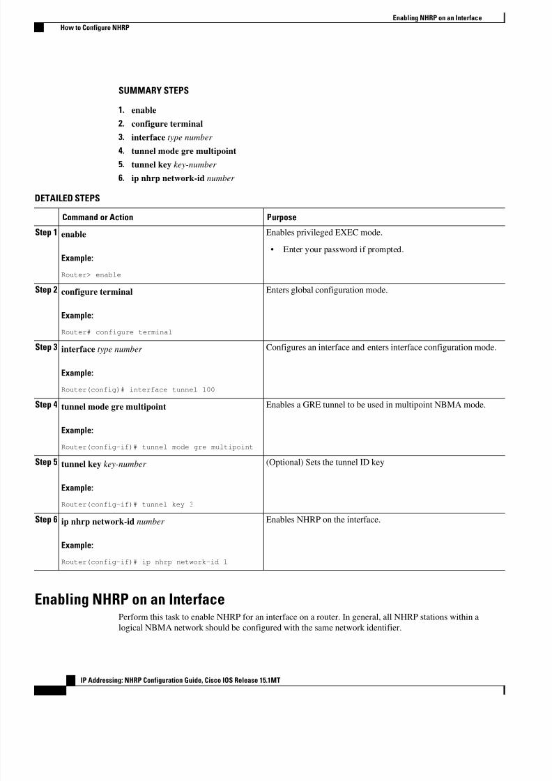
SUMMARY STEPS
1. enable
2. configure terminal
3. interface type number
4. tunnel mode gre multipoint
5. tunnel key key-number
6. ip nhrp network-id number
DETAILED STEPS
Command or Action Purpose
Step 1 enable
Example:
Router> enable
Enables privileged EXEC mode.
• Enter your password if prompted.
Step 2 configure terminal
Example:
Router# configure terminal
Enters global configuration mode.
Step 3 interface type number
Example:
Router(config)# interface tunnel 100
Configures an interface and enters interface configuration mode.
Step 4tunnel mode gre multipoint
Example:
Router(config-if)# tunnel mode gre multipoint
Enables a GRE tunnel to be used in multipoint NBMA mode.
Step 5 tunnel key key-number
Example:
Router(config-if)# tunnel key 3
(Optional) Sets the tunnel ID key
Step 6 ip nhrp network-id number
Example:Router(config-if)# ip nhrp network-id 1
Enables NHRP on the interface.
Enabling NHRP on an InterfacePerform this task to enable NHRP for an interface on a router. In general, all NHRP stations within a
logical NBMA network should be configured with the same network identifier.
Enabling NHRP on an Interface
How to Configure NHRP
IP Addressing: NHRP Configuration Guide, Cisco IOS Release 15.1MT
10
8/6/2019 Nhrp 15 1mt Book
http://slidepdf.com/reader/full/nhrp-15-1mt-book 14/51
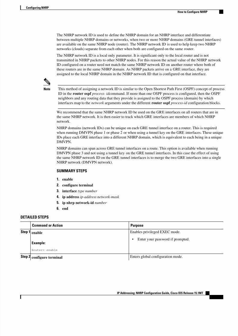
The NHRP network ID is used to define the NHRP domain for an NHRP interface and differentiate
between multiple NHRP domains or networks, when two or more NHRP domains (GRE tunnel interfaces)
are available on the same NHRP node (router). The NHRP network ID is used to help keep two NHRP
networks (clouds) separate from each other when both are configured on the same router.
The NHRP network ID is a local only parameter. It is significant only to the local router and is not
transmitted in NHRP packets to other NHRP nodes. For this reason the actual value of the NHRP network
ID configured on a router need not match the same NHRP network ID on another router where both of
these routers are in the same NHRP domain. As NHRP packets arrive on a GRE interface, they are
assigned to the local NHRP domain in the NHRP network ID that is configured on that interface.
Note This method of assigning a network ID is similar to the Open Shortest Path First (OSPF) concept of proces
ID in the router ospf process- id command. If more than one OSPF process is configured, then the OSPF
neighbors and any routing data that they provide is assigned to the OSPF process (domain) by which
interfaces map to the network arguments under the different router ospf process-id configuration blocks.
We recommend that the same NHRP network ID be used on the GRE interfaces on all routers that are in
the same NHRP network. It is then easier to track which GRE interfaces are members of which NHRPnetwork.
NHRP domains (network IDs) can be unique on each GRE tunnel interface on a router. This is required
when running DMVPN phase 1 or phase 2 or when using a tunnel key on the GRE interfaces. These unique
IDs place each GRE interface into a different NHRP domain, which is equivalent to each being in a unique
DMVPN.
NHRP domains can span across GRE tunnel interfaces on a route. This option is available when running
DMVPN phase 3 and not using a tunnel key on the GRE tunnel interfaces. In this case the effect of using
the same NHRP network ID on the GRE tunnel interfaces is to merge the two GRE interfaces into a single
NHRP network (DMVPN network).
SUMMARY STEPS
1. enable
2. configure terminal
3. interface type number
4. ip address ip-address network-mask
5. ip nhrp network-id number
6. end
DETAILED STEPS
Command or Action Purpose
Step 1 enable
Example:
Router> enable
Enables privileged EXEC mode.
• Enter your password if prompted.
Step 2 configure terminal Enters global configuration mode.
Configuring NHRP
How to Configure NHRP
IP Addressing: NHRP Configuration Guide, Cisco IOS Release 15.1MT11
8/6/2019 Nhrp 15 1mt Book
http://slidepdf.com/reader/full/nhrp-15-1mt-book 15/51
Command or Action Purpose
Example:
Router# configure terminal
Step 3 interface type number
Example:
Router(config)# interface tunnel 100
Configures an interface and enters interface configuration
mode.
Step 4 ip address ip-address network-mask
Example:
Router(config-if)# ip address 10.0.0.1 255.255.255.0
Enables IP and gives the interface an IP address.
Step 5ip nhrp network-id number
Example:
Router(config-if)# ip nhrp network-id 1
Enables NHRP on the interface.
Step 6 end
Example:
Router(config)# end
Exits interface configuration mode and returns to privileged
EXEC mode.
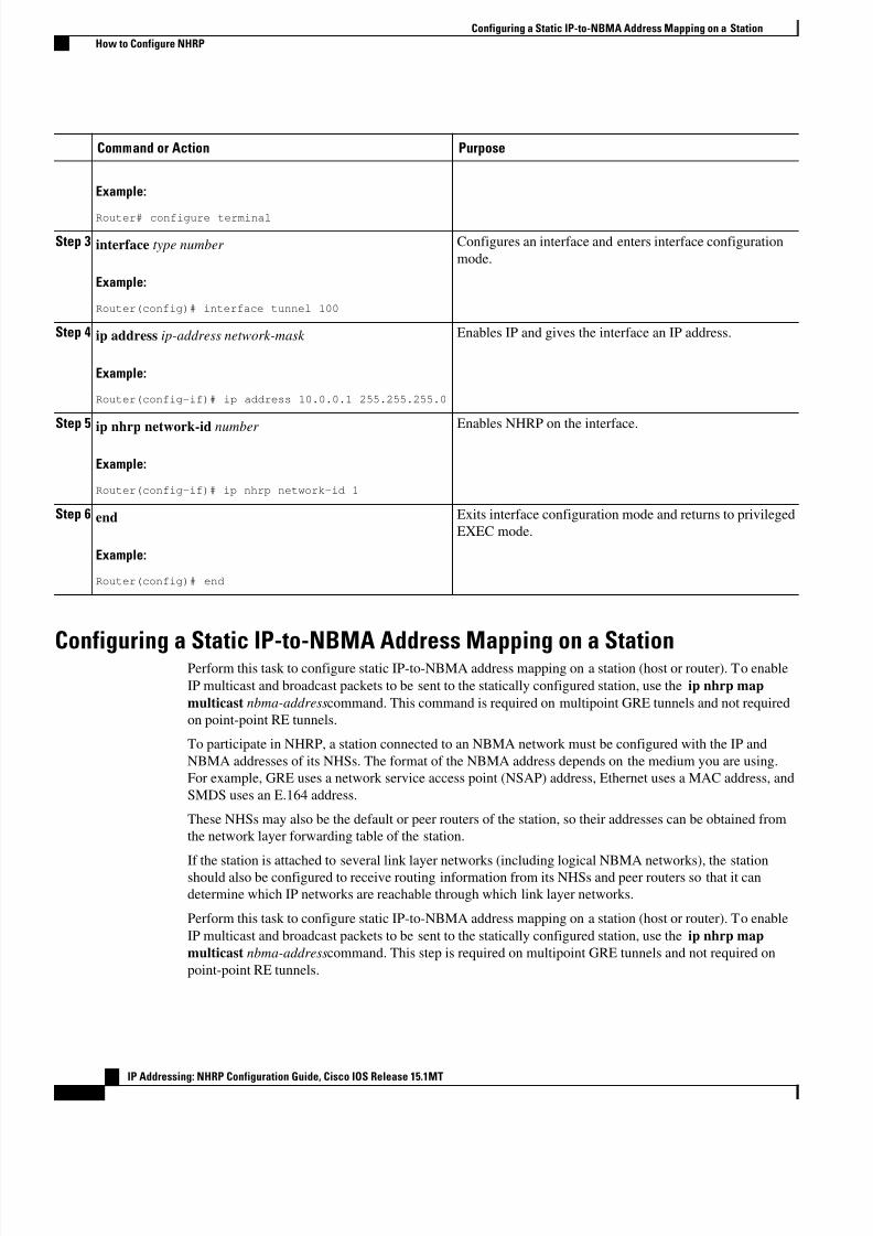
Configuring a Static IP-to-NBMA Address Mapping on a StationPerform this task to configure static IP-to-NBMA address mapping on a station (host or router). To enable
IP multicast and broadcast packets to be sent to the statically configured station, use the ip nhrp map
multicast nbma-addresscommand. This command is required on multipoint GRE tunnels and not required
on point-point RE tunnels.
To participate in NHRP, a station connected to an NBMA network must be configured with the IP and
NBMA addresses of its NHSs. The format of the NBMA address depends on the medium you are using.
For example, GRE uses a network service access point (NSAP) address, Ethernet uses a MAC address, and
SMDS uses an E.164 address.
These NHSs may also be the default or peer routers of the station, so their addresses can be obtained from
the network layer forwarding table of the station.
If the station is attached to several link layer networks (including logical NBMA networks), the stationshould also be configured to receive routing information from its NHSs and peer routers so that it can
determine which IP networks are reachable through which link layer networks.
Perform this task to configure static IP-to-NBMA address mapping on a station (host or router). To enable
IP multicast and broadcast packets to be sent to the statically configured station, use the ip nhrp map
multicast nbma-addresscommand. This step is required on multipoint GRE tunnels and not required on
point-point RE tunnels.
Configuring a Static IP-to-NBMA Address Mapping on a Station
How to Configure NHRP
IP Addressing: NHRP Configuration Guide, Cisco IOS Release 15.1MT
12
8/6/2019 Nhrp 15 1mt Book
http://slidepdf.com/reader/full/nhrp-15-1mt-book 16/51
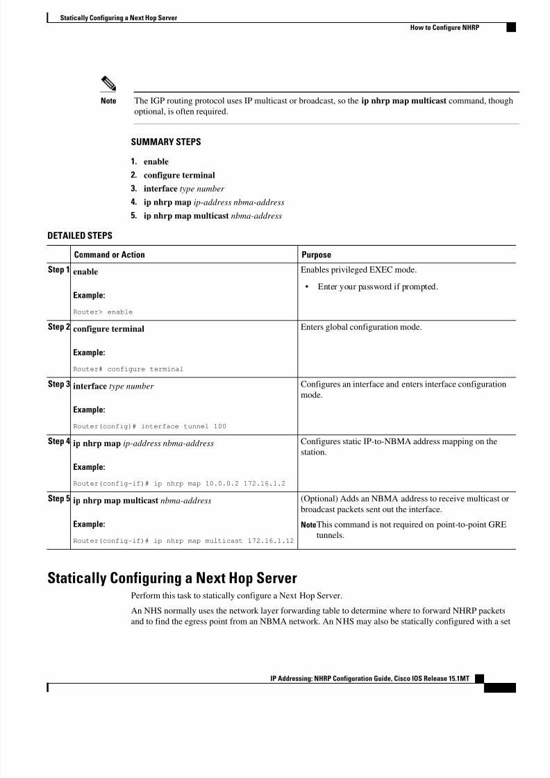
Note The IGP routing protocol uses IP multicast or broadcast, so the ip nhrp map multicast command, though
optional, is often required.
SUMMARY STEPS
1. enable
2. configure terminal
3. interface type number
4. ip nhrp map ip-address nbma-address
5. ip nhrp map multicast nbma-address
DETAILED STEPS
Command or Action Purpose
Step 1 enable
Example:
Router> enable
Enables privileged EXEC mode.
• Enter your password if prompted.
Step 2 configure terminal
Example:
Router# configure terminal
Enters global configuration mode.
Step 3 interface type number
Example:
Router(config)# interface tunnel 100
Configures an interface and enters interface configuration
mode.
Step 4 ip nhrp map ip-address nbma-address
Example:
Router(config-if)# ip nhrp map 10.0.0.2 172.16.1.2
Configures static IP-to-NBMA address mapping on the
station.
Step 5 ip nhrp map multicast nbma-address
Example:
Router(config-if)# ip nhrp map multicast 172.16.1.12
(Optional) Adds an NBMA address to receive multicast or
broadcast packets sent out the interface.
NoteThis command is not required on point-to-point GRE
tunnels.
Statically Configuring a Next Hop ServerPerform this task to statically configure a Next Hop Server.
An NHS normally uses the network layer forwarding table to determine where to forward NHRP packets
and to find the egress point from an NBMA network. An NHS may also be statically configured with a set
Statically Configuring a Next Hop Server
How to Configure NHRP
IP Addressing: NHRP Configuration Guide, Cisco IOS Release 15.1MT13
8/6/2019 Nhrp 15 1mt Book
http://slidepdf.com/reader/full/nhrp-15-1mt-book 17/51
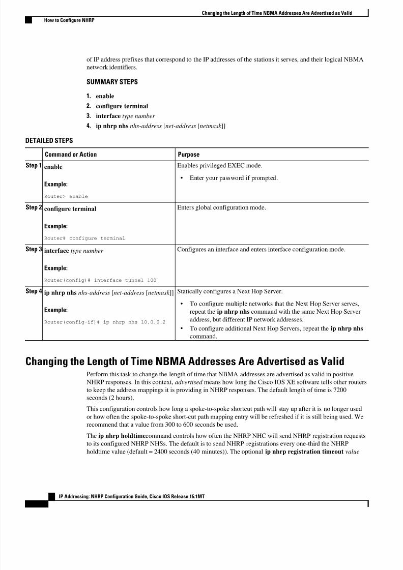
of IP address prefixes that correspond to the IP addresses of the stations it serves, and their logical NBMA
network identifiers.
SUMMARY STEPS
1. enable
2. configure terminal
3. interface type number
4. ip nhrp nhs nhs-address [net-address [netmask ]]
DETAILED STEPS
Command or Action Purpose
Step 1 enable
Example:
Router> enable
Enables privileged EXEC mode.
• Enter your password if prompted.
Step 2 configure terminal
Example:
Router# configure terminal
Enters global configuration mode.
Step 3 interface type number
Example:
Router(config)# interface tunnel 100
Configures an interface and enters interface configuration mode.
Step 4 ip nhrp nhs nhs-address [net-address [netmask ]]
Example:
Router(config-if)# ip nhrp nhs 10.0.0.2
Statically configures a Next Hop Server.
• To configure multiple networks that the Next Hop Server serves,
repeat the ip nhrp nhs command with the same Next Hop Server
address, but different IP network addresses.
• To configure additional Next Hop Servers, repeat the ip nhrp nhs
command.
Changing the Length of Time NBMA Addresses Are Advertised as ValidPerform this task to change the length of time that NBMA addresses are advertised as valid in positive
NHRP responses. In this context, advertised means how long the Cisco IOS XE software tells other routers
to keep the address mappings it is providing in NHRP responses. The default length of time is 7200
seconds (2 hours).This configuration controls how long a spoke-to-spoke shortcut path will stay up after it is no longer used
or how often the spoke-to-spoke short-cut path mapping entry will be refreshed if it is still being used. We
recommend that a value from 300 to 600 seconds be used.
The ip nhrp holdtimecommand controls how often the NHRP NHC will send NHRP registration requests
to its configured NHRP NHSs. The default is to send NHRP registrations every one-third the NHRP
holdtime value (default = 2400 seconds (40 minutes)). The optional ip nhrp registration timeout value
Changing the Length of Time NBMA Addresses Are Advertised as Valid
How to Configure NHRP
IP Addressing: NHRP Configuration Guide, Cisco IOS Release 15.1MT
14
8/6/2019 Nhrp 15 1mt Book
http://slidepdf.com/reader/full/nhrp-15-1mt-book 18/51
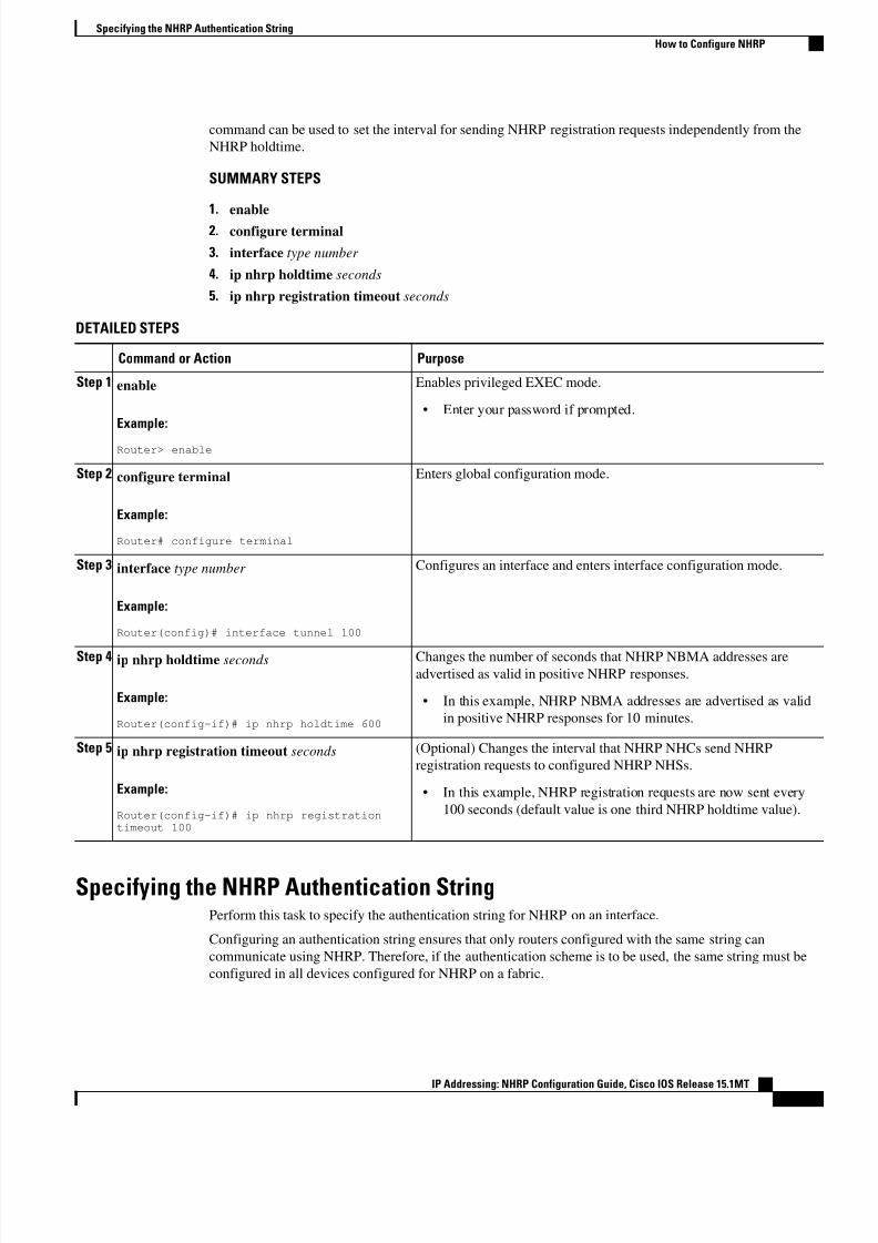
command can be used to set the interval for sending NHRP registration requests independently from the
NHRP holdtime.
SUMMARY STEPS
1. enable
2. configure terminal
3. interface type number
4. ip nhrp holdtime seconds
5. ip nhrp registration timeout seconds
DETAILED STEPS
Command or Action Purpose
Step 1 enable
Example:
Router> enable
Enables privileged EXEC mode.
• Enter your password if prompted.
Step 2 configure terminal
Example:
Router# configure terminal
Enters global configuration mode.
Step 3 interface type number
Example:
Router(config)# interface tunnel 100
Configures an interface and enters interface configuration mode.
Step 4 ip nhrp holdtime seconds
Example:
Router(config-if)# ip nhrp holdtime 600
Changes the number of seconds that NHRP NBMA addresses areadvertised as valid in positive NHRP responses.
• In this example, NHRP NBMA addresses are advertised as valid
in positive NHRP responses for 10 minutes.
Step 5 ip nhrp registration timeout seconds
Example:
Router(config-if)# ip nhrp registrationtimeout 100
(Optional) Changes the interval that NHRP NHCs send NHRP
registration requests to configured NHRP NHSs.
• In this example, NHRP registration requests are now sent every
100 seconds (default value is one third NHRP holdtime value).
Specifying the NHRP Authentication StringPerform this task to specify the authentication string for NHRP on an interface.
Configuring an authentication string ensures that only routers configured with the same string can
communicate using NHRP. Therefore, if the authentication scheme is to be used, the same string must be
configured in all devices configured for NHRP on a fabric.
Specifying the NHRP Authentication String
How to Configure NHRP
IP Addressing: NHRP Configuration Guide, Cisco IOS Release 15.1MT15
8/6/2019 Nhrp 15 1mt Book
http://slidepdf.com/reader/full/nhrp-15-1mt-book 19/51
Note We recommend using an NHRP authentication string, especially to help keep multiple NHRP domains
separate from each other. The NHRP authentication string is not encrypted, so it cannot be used as a true
authentication for an NHRP node trying to enter the NHRP network.
SUMMARY STEPS
1. enable
2. configure terminal
3. interface type number
4. ip nhrp authentication string
5. exit
6. show ip nhrp [dynamic | static] [type number ]
7. show ip nhrp traffic
8. show ip nhrp nhs [detail]
DETAILED STEPS
Command or Action Purpose
Step 1 enable
Example:
Router> enable
Enables privileged EXEC mode.
• Enter your password if prompted.
Step 2 configure terminal
Example:
Router# configure terminal
Enters global configuration mode.
Step 3 interface type number
Example:
Router(config)# interface tunnel 100
Configures an interface and enters interface configuration
mode.
Step 4 ip nhrp authentication string
Example:
Router(config-if)# ip nhrp authentication specialxx
Specifies an authentication string.
• All routers configured with NHRP within one logical
NBMA network must share the same authentication
string.
Step 5 exit
Example:
Router(config-if)# exit
Exits interface configuration mode and returns to privileged
EXEC mode.
Step 6 show ip nhrp [dynamic | static] [type number ] Displays the IP NHRP cache, which can be limited to
dynamic or static cache entries for a specific interface.
Configuring NHRP
How to Configure NHRP
IP Addressing: NHRP Configuration Guide, Cisco IOS Release 15.1MT
16
8/6/2019 Nhrp 15 1mt Book
http://slidepdf.com/reader/full/nhrp-15-1mt-book 20/51
8/6/2019 Nhrp 15 1mt Book
http://slidepdf.com/reader/full/nhrp-15-1mt-book 21/51
Command or Action Purpose
Example:
Router# configure terminal
Step 3 interface type number
Example:
Router(config)# interface tunnel 100
Configures an interface and enters interface configuration
mode.
Step 4 ip nhrp server-only [non-caching]
Example:
Router(config-if)# ip nhrp server-only non-caching
Configures NHRP server-only mode.
Controlling the Triggering of NHRPThere are two ways to control when NHRP is triggered on any platform. These methods are described in
the following sections:
• Triggering NHRP on a per-Destination Basis, page 18
• Triggering NHRP on a Packet Count Basis, page 19
Triggering NHRP on a per-Destination Basis
Perform the following task to trigger NHRP on a per-destination basis.
You can specify an IP access list that is used to decide which IP packets can trigger the sending of NHRPresolution requests. By default, all non-NHRP packets trigger NHRP resolution requests. To limit which IP
packets trigger NHRP resolution requests, define an access list and then apply it to the interface.
Note NHRP resolution requests are used to build direct paths between two NHRP nodes. Even though certain
traffic is excluded from triggering the building of this path, if the path is already built then this “excluded”
traffic will use the direct path.
SUMMARY STEPS
1. enable
2. configure terminal
3. Do one of the following:
• access-list access-list-number {deny | permit} source [source-wildcard ]
• access-list access-list-number {deny | permit} protocol source source-wildcard destination
destination-wildcard [precedence precedence] [tos tos] [established] [log]
4. interface type number
5. ip nhrp interest access-list-number
Controlling the Triggering of NHRP
Triggering NHRP on a per-Destination Basis
IP Addressing: NHRP Configuration Guide, Cisco IOS Release 15.1MT
18
8/6/2019 Nhrp 15 1mt Book
http://slidepdf.com/reader/full/nhrp-15-1mt-book 22/51
DETAILED STEPS
Command or Action Purpose
Step 1 enable
Example:
Router> enable
Enables privileged EXEC mode.
• Enter your password if prompted.
Step 2 configure terminal
Example:
Router# configure terminal
Enters global configuration mode.
Step 3 Do one of the following:
• access-list access-list-number {deny | permit} source [source-
wildcard ]• access-list access-list-number {deny | permit} protocol source
source-wildcard destination destination-wildcard [precedence
precedence] [tos tos] [established] [log]
Example:
Router(config)# access-list 101 permit ip any any
Example:
Router(config)# access-list 101 deny ip any 10.3.0.00.0.255.255
Defines a standard or extended IP access list.
Step 4interface type number
Example:
Router(config)# interface tunnel 100
Configures an interface and enters interface
configuration mode.
Step 5 ip nhrp interest access-list-number
Example:
Router(config-if)# ip nhrp interest 101
Specifies an IP access list that controls NHRP
requests.
• In this example, only the packets that pass
extended access list 101 are subject to the
default SVC triggering and teardown rates.
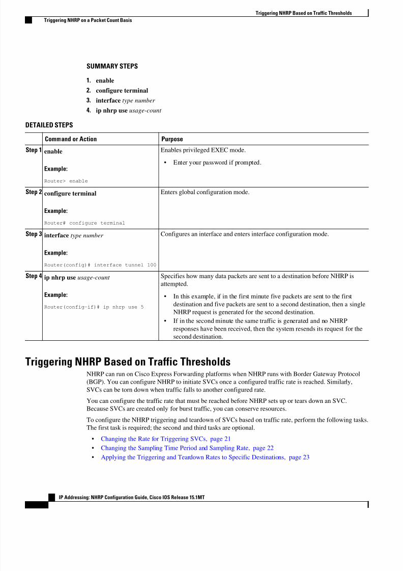
Triggering NHRP on a Packet Count BasisBy default, when the software attempts to send a data packet to a destination for which it has determined
that NHRP can be used, it sends an NHRP request for that destination. Perform this task to configure the
system to wait until a specified number of data packets have been sent to a particular destination before
NHRP is attempted.
Configuring NHRP
Triggering NHRP on a Packet Count Basis
IP Addressing: NHRP Configuration Guide, Cisco IOS Release 15.1MT19
8/6/2019 Nhrp 15 1mt Book
http://slidepdf.com/reader/full/nhrp-15-1mt-book 23/51
SUMMARY STEPS
1. enable
2. configure terminal
3. interface type number
4. ip nhrp use usage-count
DETAILED STEPS
Command or Action Purpose
Step 1 enable
Example:
Router> enable
Enables privileged EXEC mode.
• Enter your password if prompted.
Step 2 configure terminal
Example:
Router# configure terminal
Enters global configuration mode.
Step 3 interface type number
Example:
Router(config)# interface tunnel 100
Configures an interface and enters interface configuration mode.
Step 4 ip nhrp use usage-count
Example:
Router(config-if)# ip nhrp use 5
Specifies how many data packets are sent to a destination before NHRP is
attempted.
• In this example, if in the first minute five packets are sent to the first
destination and five packets are sent to a second destination, then a single
NHRP request is generated for the second destination.
• If in the second minute the same traffic is generated and no NHRP
responses have been received, then the system resends its request for the
second destination.
Triggering NHRP Based on Traffic ThresholdsNHRP can run on Cisco Express Forwarding platforms when NHRP runs with Border Gateway Protocol
(BGP). You can configure NHRP to initiate SVCs once a configured traffic rate is reached. Similarly,
SVCs can be torn down when traffic falls to another configured rate.
You can configure the traffic rate that must be reached before NHRP sets up or tears down an SVC.Because SVCs are created only for burst traffic, you can conserve resources.
To configure the NHRP triggering and teardown of SVCs based on traffic rate, perform the following tasks.
The first task is required; the second and third tasks are optional.
• Changing the Rate for Triggering SVCs, page 21
• Changing the Sampling Time Period and Sampling Rate, page 22
• Applying the Triggering and Teardown Rates to Specific Destinations, page 23
Triggering NHRP Based on Traffic Thresholds
Triggering NHRP on a Packet Count Basis
IP Addressing: NHRP Configuration Guide, Cisco IOS Release 15.1MT
20
8/6/2019 Nhrp 15 1mt Book
http://slidepdf.com/reader/full/nhrp-15-1mt-book 24/51
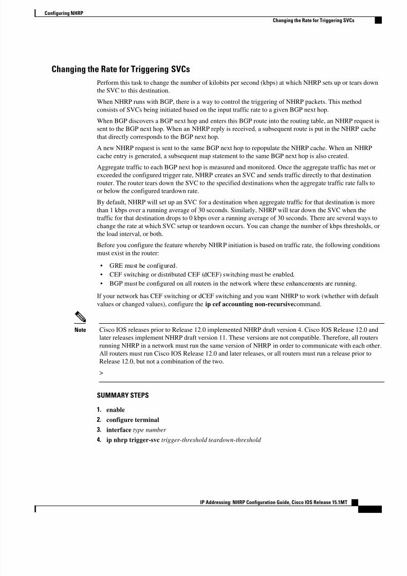
Changing the Rate for Triggering SVCs
Perform this task to change the number of kilobits per second (kbps) at which NHRP sets up or tears down
the SVC to this destination.
When NHRP runs with BGP, there is a way to control the triggering of NHRP packets. This methodconsists of SVCs being initiated based on the input traffic rate to a given BGP next hop.
When BGP discovers a BGP next hop and enters this BGP route into the routing table, an NHRP request is
sent to the BGP next hop. When an NHRP reply is received, a subsequent route is put in the NHRP cache
that directly corresponds to the BGP next hop.
A new NHRP request is sent to the same BGP next hop to repopulate the NHRP cache. When an NHRP
cache entry is generated, a subsequent map statement to the same BGP next hop is also created.
Aggregate traffic to each BGP next hop is measured and monitored. Once the aggregate traffic has met or
exceeded the configured trigger rate, NHRP creates an SVC and sends traffic directly to that destination
router. The router tears down the SVC to the specified destinations when the aggregate traffic rate falls to
or below the configured teardown rate.
By default, NHRP will set up an SVC for a destination when aggregate traffic for that destination is morethan 1 kbps over a running average of 30 seconds. Similarly, NHRP will tear down the SVC when the
traffic for that destination drops to 0 kbps over a running average of 30 seconds. There are several ways to
change the rate at which SVC setup or teardown occurs. You can change the number of kbps thresholds, or
the load interval, or both.
Before you configure the feature whereby NHRP initiation is based on traffic rate, the following conditions
must exist in the router:
• GRE must be configured.
• CEF switching or distributed CEF (dCEF) switching must be enabled.
• BGP must be configured on all routers in the network where these enhancements are running.
If your network has CEF switching or dCEF switching and you want NHRP to work (whether with default
values or changed values), configure the ip cef accounting non-recursivecommand.
Note Cisco IOS releases prior to Release 12.0 implemented NHRP draft version 4. Cisco IOS Release 12.0 and
later releases implement NHRP draft version 11. These versions are not compatible. Therefore, all routers
running NHRP in a network must run the same version of NHRP in order to communicate with each other
All routers must run Cisco IOS Release 12.0 and later releases, or all routers must run a release prior to
Release 12.0, but not a combination of the two.
>
SUMMARY STEPS
1. enable
2. configure terminal
3. interface type number
4. ip nhrp trigger-svc trigger-threshold teardown-threshold
Configuring NHRP
Changing the Rate for Triggering SVCs
IP Addressing: NHRP Configuration Guide, Cisco IOS Release 15.1MT21
8/6/2019 Nhrp 15 1mt Book
http://slidepdf.com/reader/full/nhrp-15-1mt-book 25/51
DETAILED STEPS
Command or Action Purpose
Step 1 enable
Example:
Router> enable
Enables privileged EXEC mode.
• Enter your password if prompted.
Step 2 configure terminal
Example:
Router# configure terminal
Enters global configuration mode.
Step 3 interface type number
Example:
Router(config)# interface tunnel 100
Configures an interface and enters interface configuration
mode.
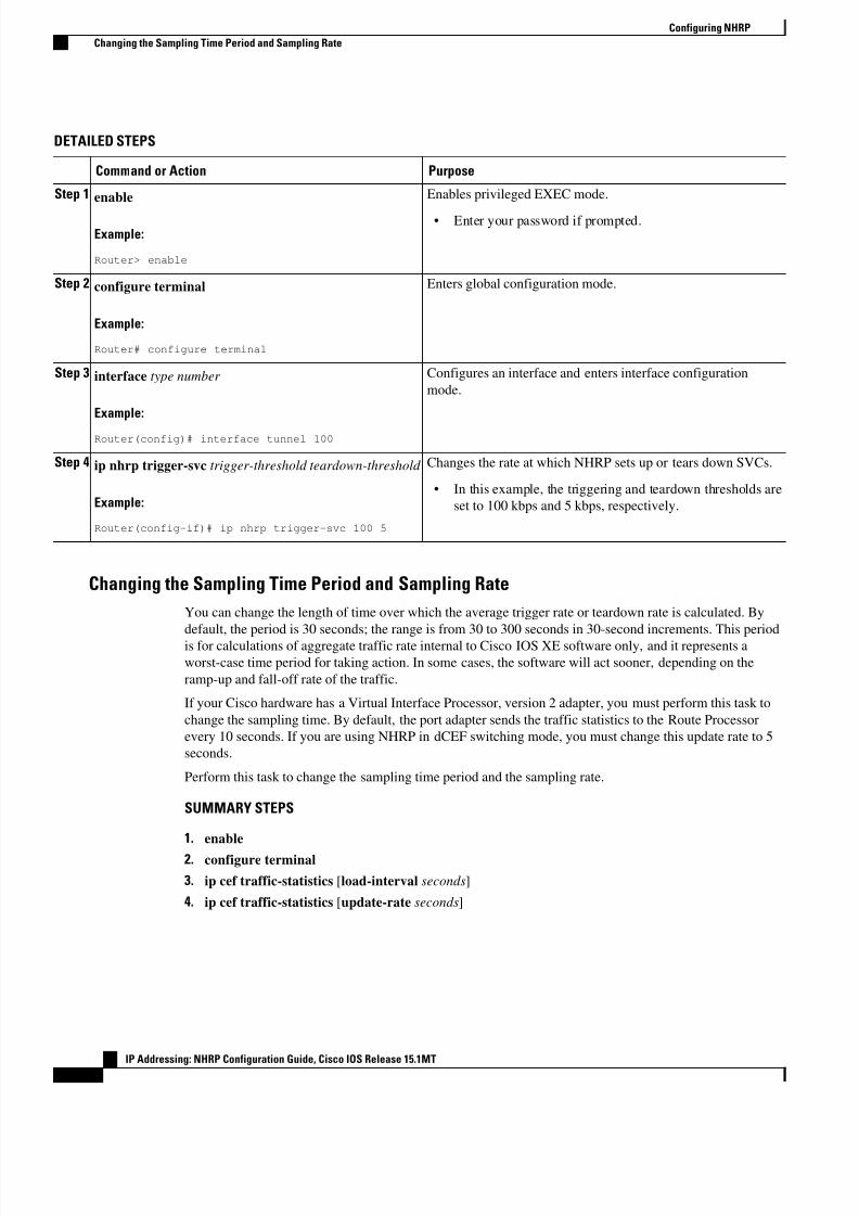
Step 4 ip nhrp trigger-svc trigger-threshold teardown-threshold
Example:
Router(config-if)# ip nhrp trigger-svc 100 5
Changes the rate at which NHRP sets up or tears down SVCs.
• In this example, the triggering and teardown thresholds are
set to 100 kbps and 5 kbps, respectively.
Changing the Sampling Time Period and Sampling Rate
You can change the length of time over which the average trigger rate or teardown rate is calculated. By
default, the period is 30 seconds; the range is from 30 to 300 seconds in 30-second increments. This period
is for calculations of aggregate traffic rate internal to Cisco IOS XE software only, and it represents a
worst-case time period for taking action. In some cases, the software will act sooner, depending on the
ramp-up and fall-off rate of the traffic.
If your Cisco hardware has a Virtual Interface Processor, version 2 adapter, you must perform this task to
change the sampling time. By default, the port adapter sends the traffic statistics to the Route Processor
every 10 seconds. If you are using NHRP in dCEF switching mode, you must change this update rate to 5
seconds.
Perform this task to change the sampling time period and the sampling rate.
SUMMARY STEPS
1. enable
2. configure terminal
3. ip cef traffic-statistics [load-interval seconds]
4. ip cef traffic-statistics [update-rate seconds]
Configuring NHRP
Changing the Sampling Time Period and Sampling Rate
IP Addressing: NHRP Configuration Guide, Cisco IOS Release 15.1MT
22
8/6/2019 Nhrp 15 1mt Book
http://slidepdf.com/reader/full/nhrp-15-1mt-book 26/51
DETAILED STEPS
Command or Action Purpose
Step 1 enable
Example:
Router> enable
Enables privileged EXEC mode.
• Enter your password if prompted.
Step 2 configure terminal
Example:
Router# configure terminal
Enters global configuration mode.
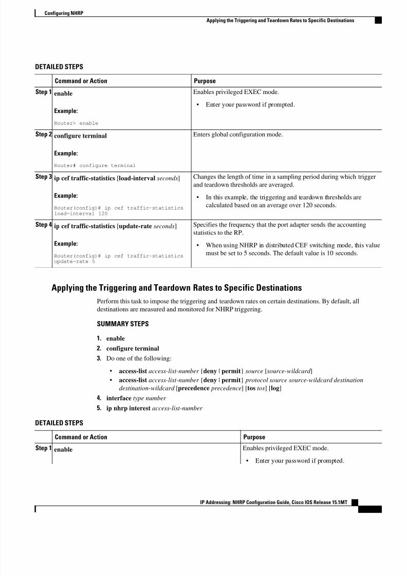
Step 3 ip cef traffic-statistics [load-interval seconds]
Example:
Router(config)# ip cef traffic-statisticsload-interval 120
Changes the length of time in a sampling period during which trigger
and teardown thresholds are averaged.
• In this example, the triggering and teardown thresholds are
calculated based on an average over 120 seconds.
Step 4 ip cef traffic-statistics [update-rate seconds]
Example:
Router(config)# ip cef traffic-statisticsupdate-rate 5
Specifies the frequency that the port adapter sends the accounting
statistics to the RP.
• When using NHRP in distributed CEF switching mode, this value
must be set to 5 seconds. The default value is 10 seconds.
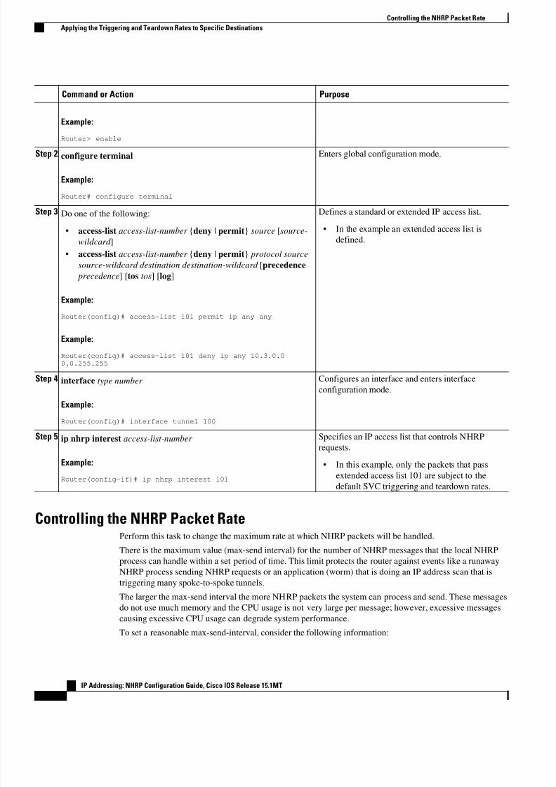
Applying the Triggering and Teardown Rates to Specific Destinations
Perform this task to impose the triggering and teardown rates on certain destinations. By default, alldestinations are measured and monitored for NHRP triggering.
SUMMARY STEPS
1. enable
2. configure terminal
3. Do one of the following:
• access-list access-list-number {deny | permit} source [source-wildcard ]
• access-list access-list-number {deny | permit} protocol source source-wildcard destination
destination-wildcard [precedence precedence] [tos tos] [log]
4. interface type number
5. ip nhrp interest access-list-number
DETAILED STEPS
Command or Action Purpose
Step 1 enable Enables privileged EXEC mode.
• Enter your password if prompted.
Configuring NHRP
Applying the Triggering and Teardown Rates to Specific Destinations
IP Addressing: NHRP Configuration Guide, Cisco IOS Release 15.1MT23
8/6/2019 Nhrp 15 1mt Book
http://slidepdf.com/reader/full/nhrp-15-1mt-book 27/51
Command or Action Purpose
Example:
Router> enable
Step 2 configure terminal
Example:
Router# configure terminal
Enters global configuration mode.
Step 3 Do one of the following:
• access-list access-list-number {deny | permit} source [source-
wildcard ]
• access-list access-list-number {deny | permit} protocol source
source-wildcard destination destination-wildcard [precedence
precedence] [tos tos] [log]
Example:
Router(config)# access-list 101 permit ip any any
Example:
Router(config)# access-list 101 deny ip any 10.3.0.00.0.255.255
Defines a standard or extended IP access list.
• In the example an extended access list is
defined.
Step 4 interface type number
Example:
Router(config)# interface tunnel 100
Configures an interface and enters interface
configuration mode.
Step 5 ip nhrp interest access-list-number
Example:
Router(config-if)# ip nhrp interest 101
Specifies an IP access list that controls NHRP
requests.
• In this example, only the packets that pass
extended access list 101 are subject to the
default SVC triggering and teardown rates.
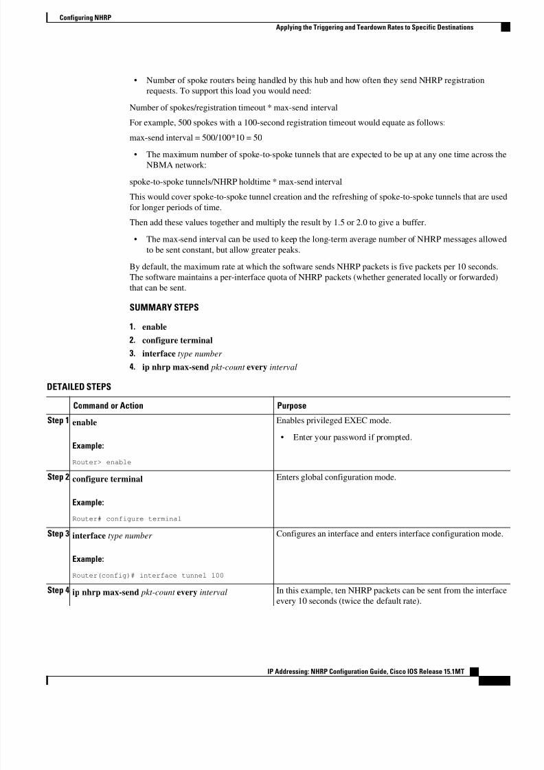
Controlling the NHRP Packet RatePerform this task to change the maximum rate at which NHRP packets will be handled.
There is the maximum value (max-send interval) for the number of NHRP messages that the local NHRPprocess can handle within a set period of time. This limit protects the router against events like a runaway
NHRP process sending NHRP requests or an application (worm) that is doing an IP address scan that is
triggering many spoke-to-spoke tunnels.
The larger the max-send interval the more NHRP packets the system can process and send. These messages
do not use much memory and the CPU usage is not very large per message; however, excessive messages
causing excessive CPU usage can degrade system performance.
To set a reasonable max-send-interval, consider the following information:
Controlling the NHRP Packet Rate
Applying the Triggering and Teardown Rates to Specific Destinations
IP Addressing: NHRP Configuration Guide, Cisco IOS Release 15.1MT
24
8/6/2019 Nhrp 15 1mt Book
http://slidepdf.com/reader/full/nhrp-15-1mt-book 28/51
• Number of spoke routers being handled by this hub and how often they send NHRP registration
requests. To support this load you would need:
Number of spokes/registration timeout * max-send interval
For example, 500 spokes with a 100-second registration timeout would equate as follows:
max-send interval = 500/100*10 = 50
• The maximum number of spoke-to-spoke tunnels that are expected to be up at any one time across the
NBMA network:
spoke-to-spoke tunnels/NHRP holdtime * max-send interval
This would cover spoke-to-spoke tunnel creation and the refreshing of spoke-to-spoke tunnels that are used
for longer periods of time.
Then add these values together and multiply the result by 1.5 or 2.0 to give a buffer.
• The max-send interval can be used to keep the long-term average number of NHRP messages allowed
to be sent constant, but allow greater peaks.
By default, the maximum rate at which the software sends NHRP packets is five packets per 10 seconds.The software maintains a per-interface quota of NHRP packets (whether generated locally or forwarded)
that can be sent.
SUMMARY STEPS
1. enable
2. configure terminal
3. interface type number
4. ip nhrp max-send pkt-count every interval
DETAILED STEPS
Command or Action Purpose
Step 1 enable
Example:
Router> enable
Enables privileged EXEC mode.
• Enter your password if prompted.
Step 2 configure terminal
Example:
Router# configure terminal
Enters global configuration mode.
Step 3interface type number
Example:
Router(config)# interface tunnel 100
Configures an interface and enters interface configuration mode.
Step 4 ip nhrp max-send pkt-count every interval In this example, ten NHRP packets can be sent from the interface
every 10 seconds (twice the default rate).
Configuring NHRP
Applying the Triggering and Teardown Rates to Specific Destinations
IP Addressing: NHRP Configuration Guide, Cisco IOS Release 15.1MT25
8/6/2019 Nhrp 15 1mt Book
http://slidepdf.com/reader/full/nhrp-15-1mt-book 29/51
Command or Action Purpose
Example:
Router(config-if)# ip nhrp max-send 10 every 10
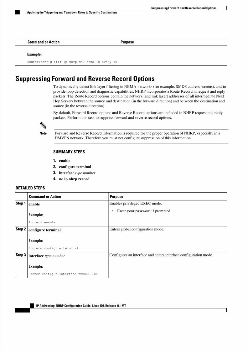
Suppressing Forward and Reverse Record OptionsTo dynamically detect link layer filtering in NBMA networks (for example, SMDS address screens), and to
provide loop detection and diagnostic capabilities, NHRP incorporates a Route Record in request and reply
packets. The Route Record options contain the network (and link layer) addresses of all intermediate Next
Hop Servers between the source and destination (in the forward direction) and between the destination and
source (in the reverse direction).
By default, Forward Record options and Reverse Record options are included in NHRP request and reply
packets. Perform this task to suppress forward and reverse record options.
Note Forward and Reverse Record information is required for the proper operation of NHRP, especially in a
DMVPN network. Therefore you must not configure suppression of this information.
SUMMARY STEPS
1. enable
2. configure terminal
3. interface type number
4. no ip nhrp record
DETAILED STEPS
Command or Action Purpose
Step 1 enable
Example:
Router> enable
Enables privileged EXEC mode.
• Enter your password if prompted.
Step 2 configure terminal
Example:
Router# configure terminal
Enters global configuration mode.
Step 3 interface type number
Example:
Router(config)# interface tunnel 100
Configures an interface and enters interface configuration mode.
Suppressing Forward and Reverse Record Options
Applying the Triggering and Teardown Rates to Specific Destinations
IP Addressing: NHRP Configuration Guide, Cisco IOS Release 15.1MT
26
8/6/2019 Nhrp 15 1mt Book
http://slidepdf.com/reader/full/nhrp-15-1mt-book 30/51
Command or Action Purpose
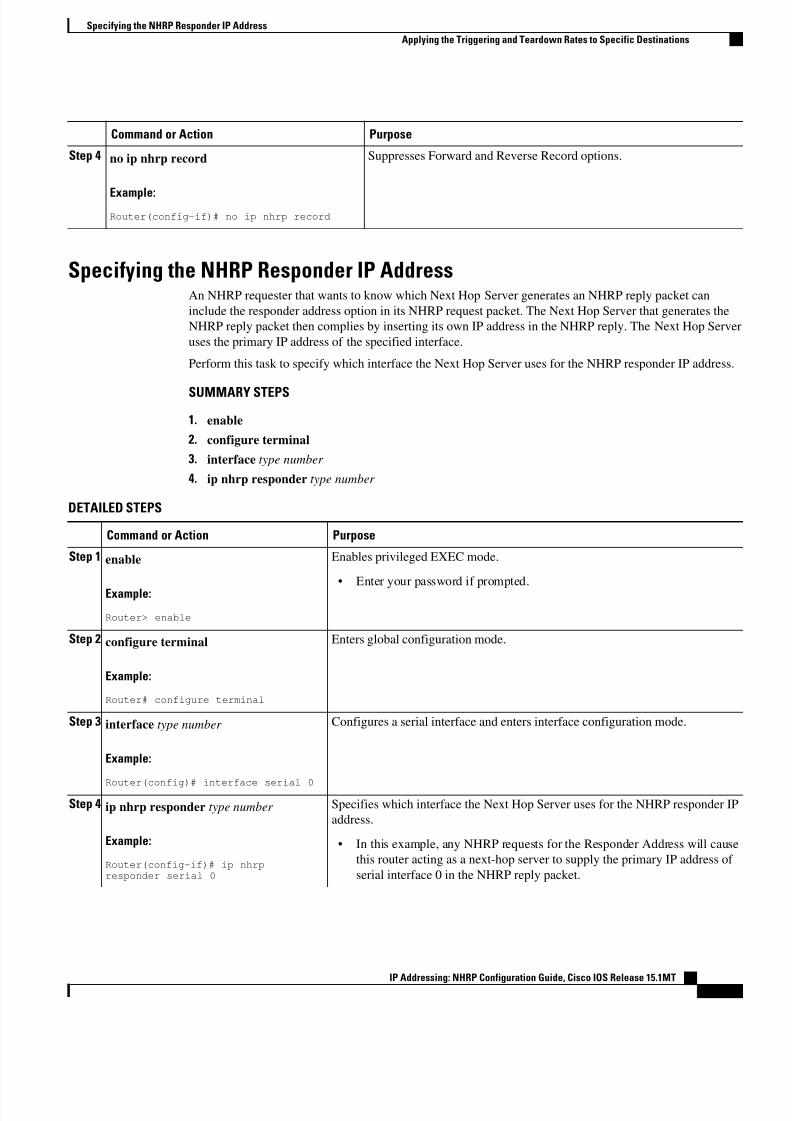
Step 4 no ip nhrp record
Example:Router(config-if)# no ip nhrp record
Suppresses Forward and Reverse Record options.
Specifying the NHRP Responder IP AddressAn NHRP requester that wants to know which Next Hop Server generates an NHRP reply packet can
include the responder address option in its NHRP request packet. The Next Hop Server that generates the
NHRP reply packet then complies by inserting its own IP address in the NHRP reply. The Next Hop Server
uses the primary IP address of the specified interface.
Perform this task to specify which interface the Next Hop Server uses for the NHRP responder IP address.
SUMMARY STEPS
1. enable
2. configure terminal
3. interface type number
4. ip nhrp responder type number
DETAILED STEPS
Command or Action Purpose
Step 1 enable
Example:
Router> enable
Enables privileged EXEC mode.
• Enter your password if prompted.
Step 2 configure terminal
Example:
Router# configure terminal
Enters global configuration mode.
Step 3 interface type number
Example:
Router(config)# interface serial 0
Configures a serial interface and enters interface configuration mode.
Step 4 ip nhrp responder type number
Example:
Router(config-if)# ip nhrpresponder serial 0
Specifies which interface the Next Hop Server uses for the NHRP responder IP
address.
• In this example, any NHRP requests for the Responder Address will cause
this router acting as a next-hop server to supply the primary IP address of
serial interface 0 in the NHRP reply packet.
Specifying the NHRP Responder IP Address
Applying the Triggering and Teardown Rates to Specific Destinations
IP Addressing: NHRP Configuration Guide, Cisco IOS Release 15.1MT27
8/6/2019 Nhrp 15 1mt Book
http://slidepdf.com/reader/full/nhrp-15-1mt-book 31/51
Command or Action Purpose
• If an NHRP reply packet being forwarded by a Next Hop Server contains
the IP address of that server, the Next Hop Server generates an error
indication of type “NHRP Loop Detected” and discards the reply.
Clearing the NHRP CacheThe NHRP cache can contain entries of statically configured NHRP mappings and dynamic entries caused
by the Cisco IOS XE software learning addresses from NHRP packets. To clear statically configured
entries, use the no ip nhrp map command in interface configuration mode.
Perform the following task to clear the NHRP cache.
SUMMARY STEPS
1. enable
2. clear ip nhrp [ip-address] [ip-mask ]
DETAILED STEPS
Command or Action Purpose
Step 1 enable
Example:
Router> enable
Enables privileged EXEC mode.
• Enter your password if prompted.
Step 2 clear ip nhrp [ip-address] [ip-mask ]
Example:
Router# clear ip nhrp
Clears the IP NHRP cache of dynamic entries.
• This command does not clear any static (configured) IP to NBMA address
mappings from the NHRP cache.
Configuration Examples for NHRP• Physical Network Designs for Logical NBMA Examples, page 28
• Applying NHRP Rates to Specific Destinations Example, page 30
• NHRP on a Multipoint Tunnel Example, page 31
• Show NHRP Examples, page 32
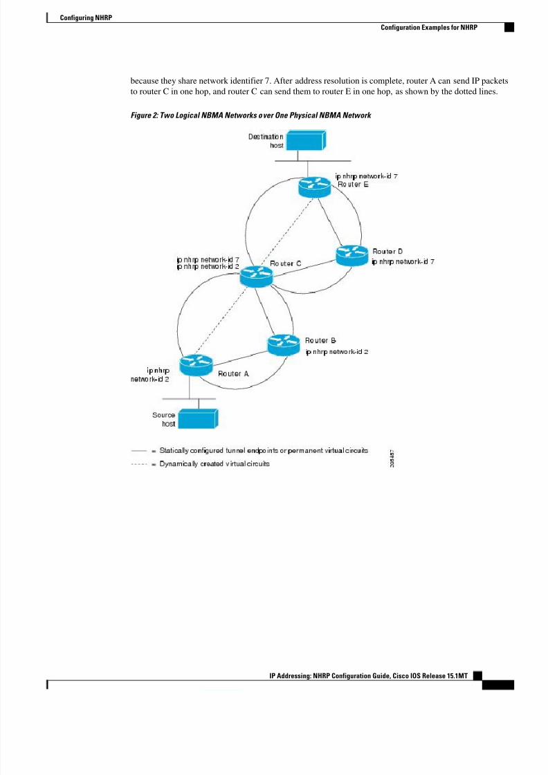
Physical Network Designs for Logical NBMA ExamplesA logical NBMA network is considered the group of interfaces and hosts participating in NHRP and having
the same network identifier. The figure below illustrates two logical NBMA networks (shown as circles)
configured over a single physical NBMA network. Router A can communicate with routers B and C
because they share the same network identifier (2). Router C can also communicate with routers D and E
Clearing the NHRP Cache
Configuration Examples for NHRP
IP Addressing: NHRP Configuration Guide, Cisco IOS Release 15.1MT
28
8/6/2019 Nhrp 15 1mt Book
http://slidepdf.com/reader/full/nhrp-15-1mt-book 32/51
8/6/2019 Nhrp 15 1mt Book
http://slidepdf.com/reader/full/nhrp-15-1mt-book 33/51
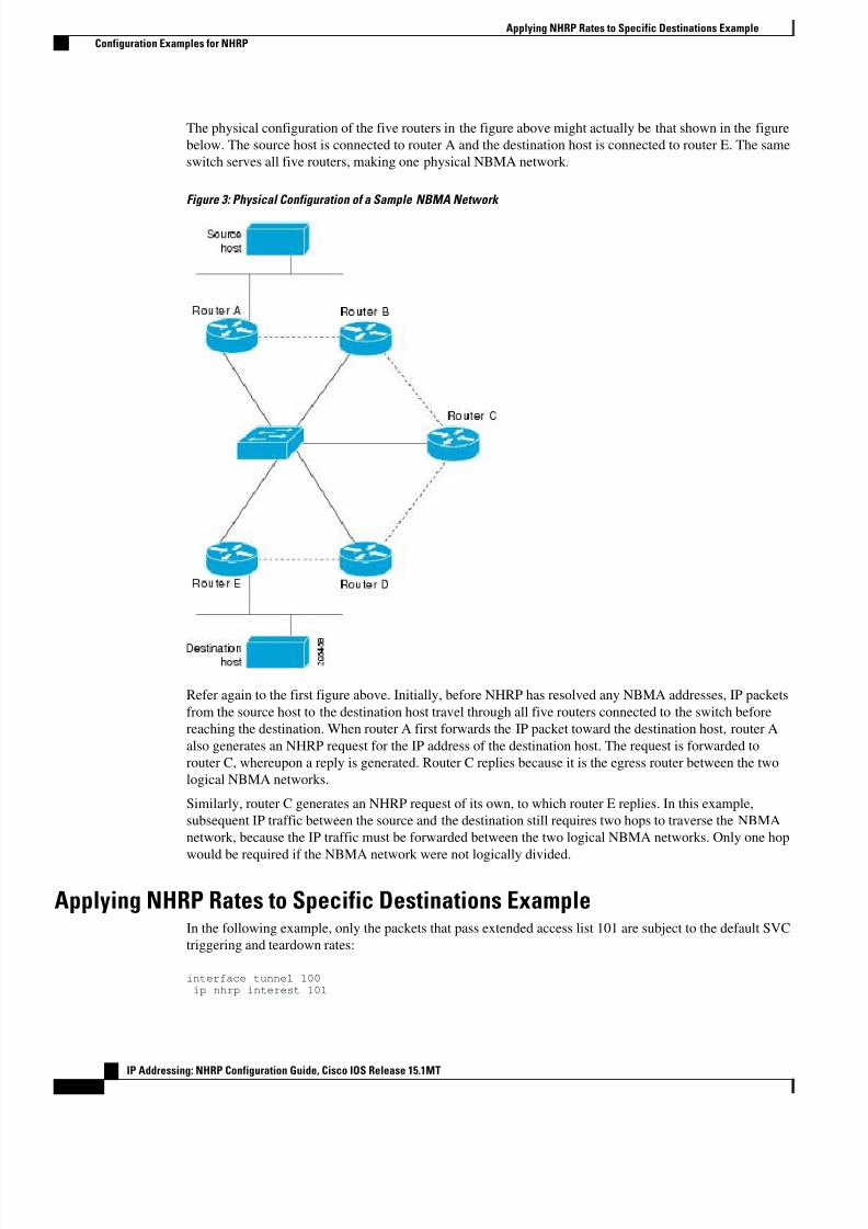
The physical configuration of the five routers in the figure above might actually be that shown in the figure
below. The source host is connected to router A and the destination host is connected to router E. The same
switch serves all five routers, making one physical NBMA network.
Figure 3: Physical Configuration of a Sample NBMA Network
Refer again to the first figure above. Initially, before NHRP has resolved any NBMA addresses, IP packets
from the source host to the destination host travel through all five routers connected to the switch before
reaching the destination. When router A first forwards the IP packet toward the destination host, router A
also generates an NHRP request for the IP address of the destination host. The request is forwarded to
router C, whereupon a reply is generated. Router C replies because it is the egress router between the two
logical NBMA networks.
Similarly, router C generates an NHRP request of its own, to which router E replies. In this example,
subsequent IP traffic between the source and the destination still requires two hops to traverse the NBMA
network, because the IP traffic must be forwarded between the two logical NBMA networks. Only one hop
would be required if the NBMA network were not logically divided.
Applying NHRP Rates to Specific Destinations ExampleIn the following example, only the packets that pass extended access list 101 are subject to the default SVC
triggering and teardown rates:
interface tunnel 100ip nhrp interest 101
Applying NHRP Rates to Specific Destinations Example
Configuration Examples for NHRP
IP Addressing: NHRP Configuration Guide, Cisco IOS Release 15.1MT
30
8/6/2019 Nhrp 15 1mt Book
http://slidepdf.com/reader/full/nhrp-15-1mt-book 34/51
!access-list 101 permit ip any anyaccess-list 101 deny ip any 10.3.0.0 0.0.255.255
NHRP on a Multipoint Tunnel ExampleWith multipoint tunnels, a single tunnel interface may be connected to multiple neighboring routers. Unlike
point-to-point tunnels, a tunnel destination need not be configured. In fact, if configured, the tunnel
destination must correspond to an IP multicast address. Broadcast or multicast packets to be sent over the
tunnel interface can then be sent by sending the GRE packet to the multicast address configured as the
tunnel destination.
Multipoint tunnels require that you configure a tunnel key. Otherwise, unexpected GRE traffic could easily
be received by the tunnel interface. For simplicity, we recommend that the tunnel key correspond to the
NHRP network identifier.
In the following example, routers A, B, C, and D all share an Ethernet segment. Minimal connectivity over
the multipoint tunnel network is configured, thus creating a network that can be treated as a partially
meshed NBMA network. Due to the static NHRP map entries, router A knows how to reach router B,
router B knows how to reach router C, router C knows how to reach router D, and router D knows how to
reach Router A.
When router A initially attempts to send an IP packet to router D, the packet is forwarded through routers B
and C. The routers use NHRP to quickly learn the NBMA addresses of each other (in this case, IP
addresses assigned to the underlying Ethernet network). The partially meshed tunnel network readily
becomes fully meshed, at which point any of the routers can directly communicate over the tunnel network
without their IP traffic requiring an intermediate hop.
The significant portions of the configurations for routers A, B, C, and D follow:
Router A Configuration
interface tunnel 0no ip redirects
ip address 10.0.0.1 255.0.0.0ip nhrp map 10.0.0.2 10.10.0.2ip nhrp network-id 1ip nhrp nhs 10.10.0.2tunnel source ethernet 0tunnel mode gre multipointtunnel key 1interface ethernet 0ip address 10.0.0.7 255.0.0.0
Router B Configuration
interface tunnel 0no ip redirectsip address 10.0.0.2 255.0.0.0ip nhrp map 10.0.0.3 10.10.0.3ip nhrp network-id 1
ip nhrp nhs 10.0.0.3tunnel source ethernet 0tunnel mode gre multipointtunnel key 1interface ethernet 0ip address 10.0.0.6 255.0.0.0
Router C Configuration
interface tunnel 0
NHRP on a Multipoint Tunnel Example
Configuration Examples for NHRP
IP Addressing: NHRP Configuration Guide, Cisco IOS Release 15.1MT31
8/6/2019 Nhrp 15 1mt Book
http://slidepdf.com/reader/full/nhrp-15-1mt-book 35/51
no ip redirectsip address 10.0.0.3 255.0.0.0ip nhrp map 10.0.0.4 10.10.0.4ip nhrp network-id 1ip nhrp nhs 10.0.0.4tunnel source ethernet 0tunnel mode gre multipointtunnel key 1interface ethernet 0ip address 10.0.0.5 255.0.0.0
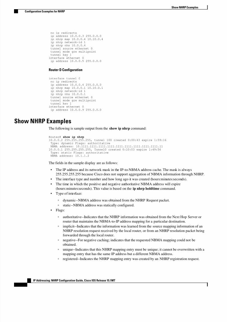
Router D Configuration
interface tunnel 0no ip redirectsip address 10.0.0.4 255.0.0.0ip nhrp map 10.0.0.1 10.10.0.1ip nhrp network-id 1ip nhrp nhs 10.0.0.1tunnel source ethernet 0tunnel mode gre multipointtunnel key 1interface ethernet 0ip address 10.0.0.9 255.0.0.0
Show NHRP ExamplesThe following is sample output from the show ip nhrp command:
Router# show ip nhrp10.0.0.2 255.255.255.255, tunnel 100 created 0:00:43 expire 1:59:16Type: dynamic Flags: authoritativeNBMA address: 10.1111.1111.1111.1111.1111.1111.1111.1111.1111.1110.0.0.1 255.255.255.255, Tunnel0 created 0:10:03 expire 1:49:56Type: static Flags: authoritativeNBMA address: 10.1.1.2
The fields in the sample display are as follows:
• The IP address and its network mask in the IP-to-NBMA address cache. The mask is always255.255.255.255 because Cisco does not support aggregation of NBMA information through NHRP.
• The interface type and number and how long ago it was created (hours:minutes:seconds).
• The time in which the positive and negative authoritative NBMA address will expire
(hours:minutes:seconds). This value is based on the ip nhrp holdtime command.
• Type of interface:
◦ dynamic--NBMA address was obtained from the NHRP Request packet.
◦ static--NBMA address was statically configured.
• Flags:
◦ authoritative--Indicates that the NHRP information was obtained from the Next Hop Server or
router that maintains the NBMA-to-IP address mapping for a particular destination.
◦ implicit--Indicates that the information was learned from the source mapping information of anNHRP resolution request received by the local router, or from an NHRP resolution packet being
forwarded through the local router.
◦ negative--For negative caching; indicates that the requested NBMA mapping could not be
obtained.
◦ unique--Indicates that this NHRP mapping entry must be unique; it cannot be overwritten with a
mapping entry that has the same IP address but a different NBMA address.
◦ registered--Indicates the NHRP mapping entry was created by an NHRP registration request.
Show NHRP Examples
Configuration Examples for NHRP
IP Addressing: NHRP Configuration Guide, Cisco IOS Release 15.1MT
32
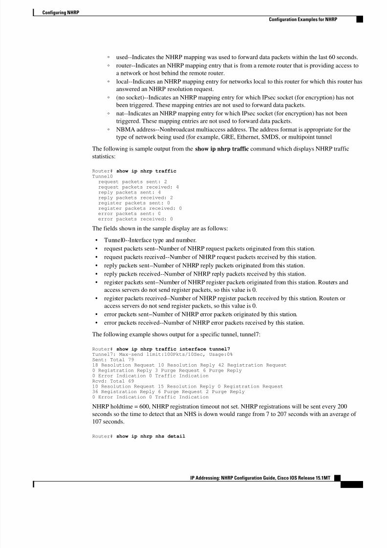
8/6/2019 Nhrp 15 1mt Book
http://slidepdf.com/reader/full/nhrp-15-1mt-book 36/51
◦ used--Indicates the NHRP mapping was used to forward data packets within the last 60 seconds.
◦ router--Indicates an NHRP mapping entry that is from a remote router that is providing access to
a network or host behind the remote router.
◦ local--Indicates an NHRP mapping entry for networks local to this router for which this router has
answered an NHRP resolution request.
◦ (no socket)--Indicates an NHRP mapping entry for which IPsec socket (for encryption) has notbeen triggered. These mapping entries are not used to forward data packets.
◦ nat--Indicates an NHRP mapping entry for which IPsec socket (for encryption) has not been
triggered. These mapping entries are not used to forward data packets.
◦ NBMA address--Nonbroadcast multiaccess address. The address format is appropriate for the
type of network being used (for example, GRE, Ethernet, SMDS, or multipoint tunnel
The following is sample output from the show ip nhrp traffic command which displays NHRP traffic
statistics:
Router# show ip nhrp trafficTunnel0request packets sent: 2request packets received: 4
reply packets sent: 4reply packets received: 2register packets sent: 0register packets received: 0error packets sent: 0error packets received: 0
The fields shown in the sample display are as follows:
• Tunnel0--Interface type and number.
• request packets sent--Number of NHRP request packets originated from this station.
• request packets received--Number of NHRP request packets received by this station.
• reply packets sent--Number of NHRP reply packets originated from this station.
• reply packets received--Number of NHRP reply packets received by this station.
• register packets sent--Number of NHRP register packets originated from this station. Routers and
access servers do not send register packets, so this value is 0.
• register packets received--Number of NHRP register packets received by this station. Routers or
access servers do not send register packets, so this value is 0.
• error packets sent--Number of NHRP error packets originated by this station.
• error packets received--Number of NHRP error packets received by this station.
The following example shows output for a specific tunnel, tunnel7:
Router# show ip nhrp traffic interface tunnel7Tunnel7: Max-send limit:100Pkts/10Sec, Usage:0%Sent: Total 7918 Resolution Request 10 Resolution Reply 42 Registration Request0 Registration Reply 3 Purge Request 6 Purge Reply0 Error Indication 0 Traffic IndicationRcvd: Total 6910 Resolution Request 15 Resolution Reply 0 Registration Request36 Registration Reply 6 Purge Request 2 Purge Reply0 Error Indication 0 Traffic Indication
NHRP holdtime = 600, NHRP registration timeout not set. NHRP registrations will be sent every 200
seconds so the time to detect that an NHS is down would range from 7 to 207 seconds with an average of
107 seconds.
Router# show ip nhrp nhs detail
Configuring NHRP
Configuration Examples for NHRP
IP Addressing: NHRP Configuration Guide, Cisco IOS Release 15.1MT33
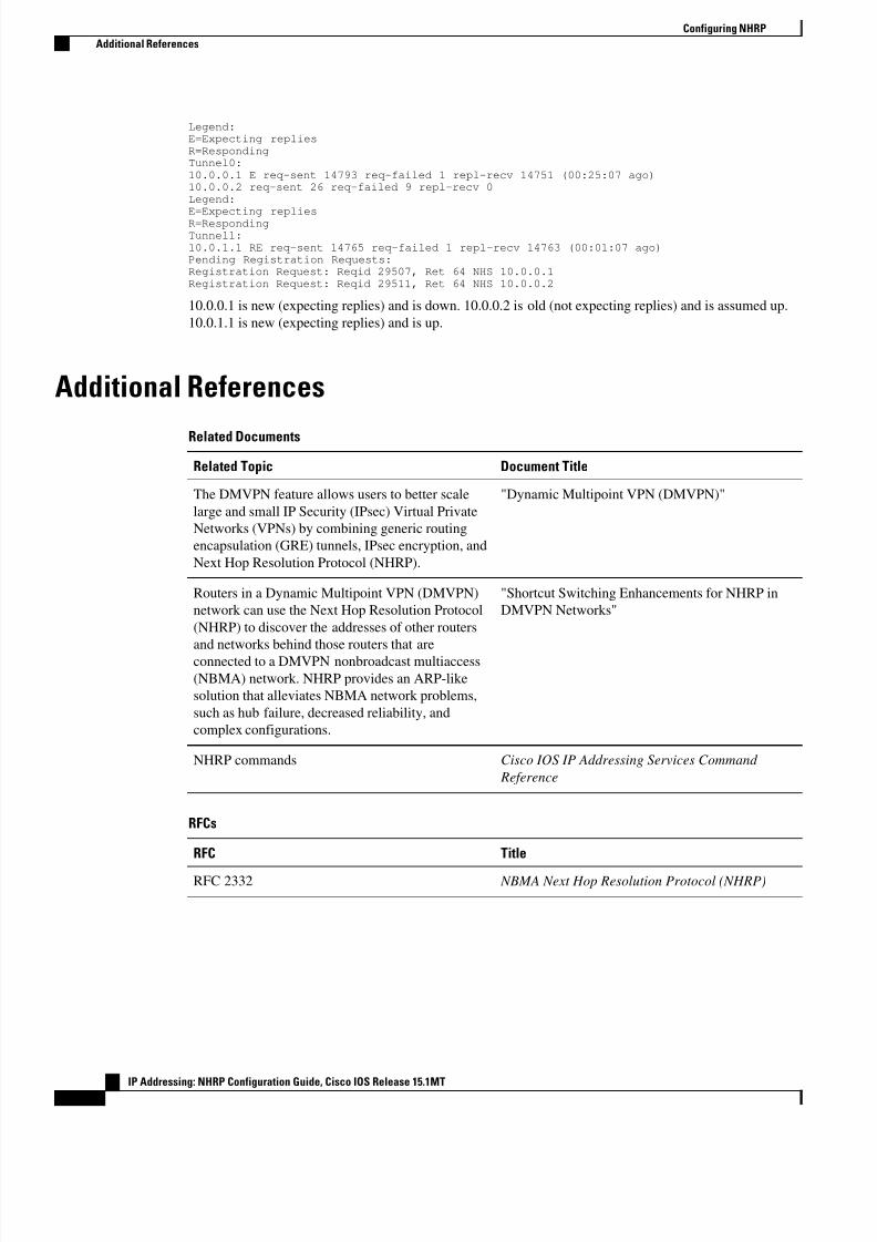
8/6/2019 Nhrp 15 1mt Book
http://slidepdf.com/reader/full/nhrp-15-1mt-book 37/51
Legend:E=Expecting repliesR=RespondingTunnel0:10.0.0.1 E req-sent 14793 req-failed 1 repl-recv 14751 (00:25:07 ago)10.0.0.2 req-sent 26 req-failed 9 repl-recv 0Legend:E=Expecting repliesR=RespondingTunnel1:10.0.1.1 RE req-sent 14765 req-failed 1 repl-recv 14763 (00:01:07 ago)Pending Registration Requests:Registration Request: Reqid 29507, Ret 64 NHS 10.0.0.1Registration Request: Reqid 29511, Ret 64 NHS 10.0.0.2
10.0.0.1 is new (expecting replies) and is down. 10.0.0.2 is old (not expecting replies) and is assumed up.
10.0.1.1 is new (expecting replies) and is up.
Additional References
Related Documents
Related Topic Document Title
The DMVPN feature allows users to better scale
large and small IP Security (IPsec) Virtual Private
Networks (VPNs) by combining generic routing
encapsulation (GRE) tunnels, IPsec encryption, and
Next Hop Resolution Protocol (NHRP).
"Dynamic Multipoint VPN (DMVPN)"
Routers in a Dynamic Multipoint VPN (DMVPN)
network can use the Next Hop Resolution Protocol
(NHRP) to discover the addresses of other routers
and networks behind those routers that are
connected to a DMVPN nonbroadcast multiaccess
(NBMA) network. NHRP provides an ARP-like
solution that alleviates NBMA network problems,
such as hub failure, decreased reliability, and
complex configurations.
"Shortcut Switching Enhancements for NHRP in
DMVPN Networks"
NHRP commands Cisco IOS IP Addressing Services Command
Reference
RFCs
RFC Title
RFC 2332 NBMA Next Hop Resolution Protocol (NHRP)
Configuring NHRP
Additional References
IP Addressing: NHRP Configuration Guide, Cisco IOS Release 15.1MT
34
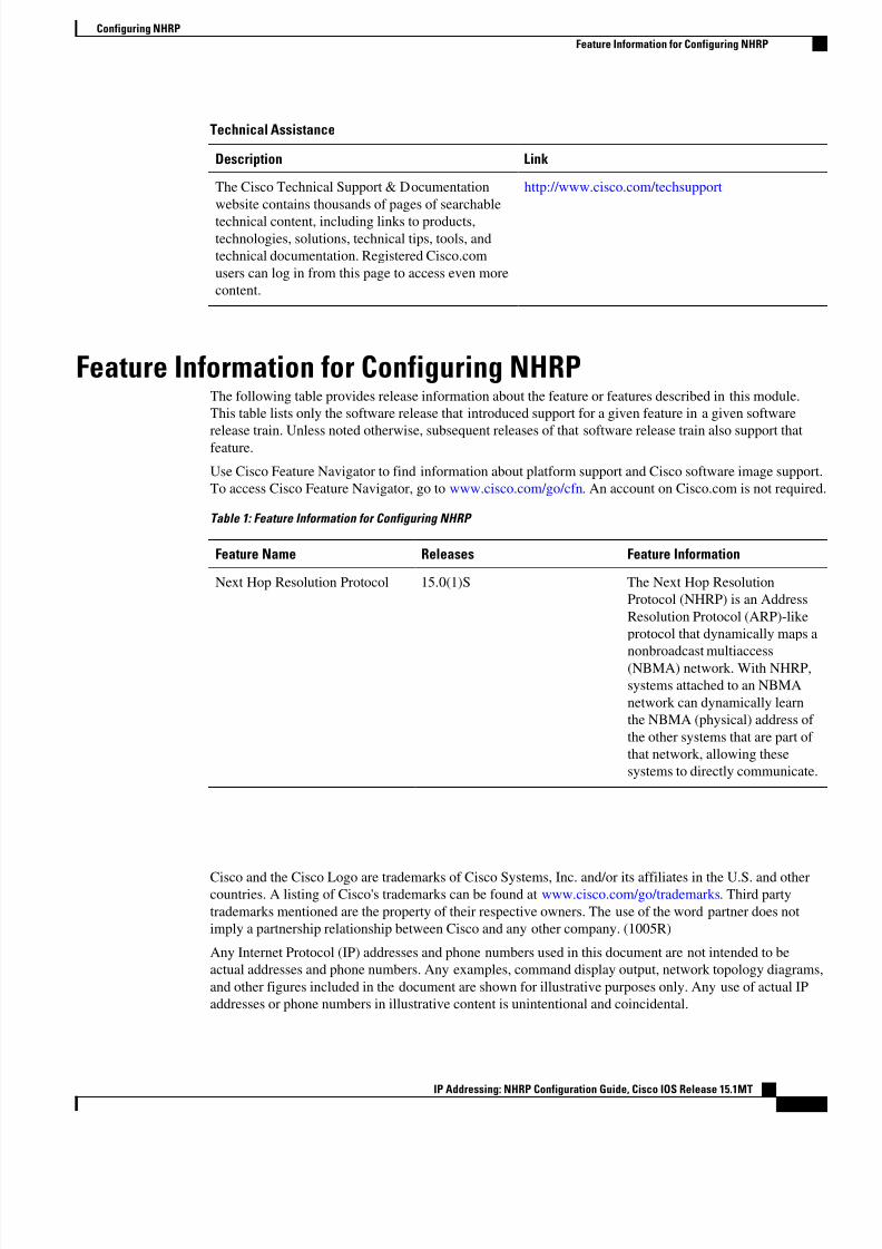
8/6/2019 Nhrp 15 1mt Book
http://slidepdf.com/reader/full/nhrp-15-1mt-book 38/51
Technical Assistance
Description Link
The Cisco Technical Support & Documentation
website contains thousands of pages of searchable
technical content, including links to products,technologies, solutions, technical tips, tools, and
technical documentation. Registered Cisco.com
users can log in from this page to access even more
content.
http://www.cisco.com/techsupport
Feature Information for Configuring NHRPThe following table provides release information about the feature or features described in this module.
This table lists only the software release that introduced support for a given feature in a given software
release train. Unless noted otherwise, subsequent releases of that software release train also support thatfeature.
Use Cisco Feature Navigator to find information about platform support and Cisco software image support.
To access Cisco Feature Navigator, go to www.cisco.com/go/cfn. An account on Cisco.com is not required
Table 1: Feature Information for Configuring NHRP
Feature Name Releases Feature Information
Next Hop Resolution Protocol 15.0(1)S The Next Hop Resolution
Protocol (NHRP) is an Address
Resolution Protocol (ARP)-like
protocol that dynamically maps a
nonbroadcast multiaccess(NBMA) network. With NHRP,
systems attached to an NBMA
network can dynamically learn
the NBMA (physical) address of
the other systems that are part of
that network, allowing these
systems to directly communicate.
Cisco and the Cisco Logo are trademarks of Cisco Systems, Inc. and/or its affiliates in the U.S. and othercountries. A listing of Cisco's trademarks can be found at www.cisco.com/go/trademarks. Third party
trademarks mentioned are the property of their respective owners. The use of the word partner does not
imply a partnership relationship between Cisco and any other company. (1005R)
Any Internet Protocol (IP) addresses and phone numbers used in this document are not intended to be
actual addresses and phone numbers. Any examples, command display output, network topology diagrams,
and other figures included in the document are shown for illustrative purposes only. Any use of actual IP
addresses or phone numbers in illustrative content is unintentional and coincidental.
Configuring NHRP
Feature Information for Configuring NHRP
IP Addressing: NHRP Configuration Guide, Cisco IOS Release 15.1MT35

8/6/2019 Nhrp 15 1mt Book
http://slidepdf.com/reader/full/nhrp-15-1mt-book 39/51
Configuring NHRP
IP Addressing: NHRP Configuration Guide, Cisco IOS Release 15.1MT
36
8/6/2019 Nhrp 15 1mt Book
http://slidepdf.com/reader/full/nhrp-15-1mt-book 40/51
8/6/2019 Nhrp 15 1mt Book
http://slidepdf.com/reader/full/nhrp-15-1mt-book 41/51
and Cisco 7301 routers. It specifically is not available for the Catalyst 6500 or Cisco 7600 series
routers.
• Do not use this feature if DMVPN is configured with a partial full-mesh configuration; that is, if the
router is configured with IP next-hop to be the IP address of the other spoke, then this feature is not
required and must not be configured. In a full-mesh configuration the spokes are populated with a full
routing table with next-hop being the other spokes.
Information About Shortcut Switching Enhancements forNHRP
• NHRP in DMVPN Networks Overview, page 38
• Benefits of NHRP Shortcut Switching Enhancements, page 39
• NHRP Mapping and Adjacency Override, page 40
• NHRP Purge Request Reply, page 42
NHRP in DMVPN Networks OverviewIn previous implementations of DMVPN, the hub uses NHRP to maintain a database of the spokes’ real
(publicly reachable) IP addresses. Spokes in a DMVPN network register their real IP address with the hub
using periodic NHRP registration packets. When a spoke has traffic for a destination behind another spoke,
it uses an NHRP resolution request to query the NHRP database on the hub for the NBMA address of
destination spokes. NHRP uses the resolution request process to build a direct spoke-to-spoke tunnel.
However, there were some issues with scaling implementations of DMVPN networks to large sizes (large
number of spokes):
• In order for the spoke to “know” to send an NHRP resolution request to build a spoke-to-spoke tunnel,
the spoke must have a route in its routing table for the remote network (behind the remote spoke) with
an IP next-hop of the tunnel IP address of the remote spoke. Having each route in the routing tablemeans that in a DMVPN network with 1000 spokes, each spoke router must have at least 1000 routes,
one for each remote spoke. Having each route in the routing table also means that the hub router that
helps in distributing this routing information must deal with the equivalent of 1,000,000 routes. The
hub receives at least one route from each spoke, and the hub must advertise all of these routes to all of
the other spokes; that is, 1000 routes advertised to 1000 spokes, which equals the processing of
1,000,000 routes. Supporting a routing table of that size can put a significant strain on the hub and
routing protocol processing.
• When using the Open Shortest Path First (OSPF) routing protocol, OSPF must be configured to use
broadcast network mode. Using broadcast network mode limits the number of hubs in a DMVPN
network to just two. Only two hubs may be used because OSPF broadcast networks require a
designated router (DR) and a backup designated router (BDR), and each spoke must be connected to
both the DR and BDR. This configuration effectively limits the DMVPN network to two hubs when
using OSPF.
• When using other routing protocols such as On-Demand Routing (ODR), which can only advertise a
default-route 0.0.0.0/0 with an IP next-hop of the hub, the implementation could not support spoke-to-
spoke tunnels.
• In order to scale DMVPN networks to larger sizes, multiple hubs are used where each one handles a
subset of the spokes. For example, to handle 2000 spokes you could use four hubs, each one handling
500 spokes. The DMVPN implementation relied on hubs being “daisy-chained” together as NHRP
Next Hop Servers (NHSs) of each other. In the case of daisy-chaining hubs, limitations included single
NHRP in DMVPN Networks Overview
Information About Shortcut Switching Enhancements for NHRP
IP Addressing: NHRP Configuration Guide, Cisco IOS Release 15.1MT
38
8/6/2019 Nhrp 15 1mt Book
http://slidepdf.com/reader/full/nhrp-15-1mt-book 42/51
hub failures breaking the chain, complexity in configuring multiple daisy chains to work around single
hub failures, and delays in response time for building spoke-to-spoke tunnels as the chain of hubs
grew.
• The DMVPN implementation only allowed a single hub spoke layer; hubs could not be spokes of othe
hubs within the same DMVPN network. You could not build complex DMVPN networks, such as
having regional hubs that are spokes of central hubs. To build a similar design in previousimplementations, you would have to set up different regional DMVPN networks with spokes
connected to regional hubs and then interconnect the regional hubs outside of the DMVPN network or
in a different DMVPN network. This design would mean that spokes in a region could only build
spoke-to-spoke tunnels to spokes within the same region (same DMVPN network), but not to spokes
in another region (different DMVPN network).
• In previous DMVPN implementations, the data packets were process switched at each hop along the
daisy chain until the spoke-to-spoke tunnel was established. Process switching of data packets could
result in unreasonable delays.
Benefits of NHRP Shortcut Switching Enhancements
The Shortcut Switching Enhancements for NHRP in DMVPN Networks feature provides a more scalablealternative to the previous NHRP model.
Cisco has developed NHRP shortcut switching model enhancements that allow for more scalable DMVPN
implementations. This model provides the following advantages over previous DMVPN implementations:
• Allows summarization of routing protocol updates from hub to spokes. The spokes no longer need to
have an individual route with an IP next-hop of the tunnel IP address of the remote spoke for the
networks behind all the other spokes. The spoke can use summarized routes with an IP next-hop of the
tunnel IP address of the hub and still be able to build spoke-to-spoke tunnels. It can reduce the load on
the routing protocol running on the hub router. You can reduce the load because, when you can
summarize the networks behind the spokes to a few summary routes or even one summary route, the
hub routing protocol only has to advertise the few or one summary route to each spoke rather than all
of the individual spoke routes. For example, with 1000 spokes and one router per spoke, the hub
receives 1000 routes but only has to advertise one summary route to each spoke (equivalent to 1000advertisements one per spoke) instead of the 1,000,000 advertisements it had to process in the prior
implementation of DMVPN.
• Provides better alternatives to static daisy chaining of hubs for expanding DMVPN spoke-to-spoke
networks. The hubs must still be interconnected, but they are not restricted to just a daisy-chain
pattern. The routing table is used to forward data packets and NHRP control packets between the hubs.
The routing table allows efficient forwarding of packets to the correct hub rather than having request
and reply packets traversing through all of the hub routers.
• Allows for expansion of DMVPN spoke-to-spoke networks with OSPF as the routing protocol beyond
two hubs. Because the spokes can use routes with the IP next-hop set to the hub router (not the remote
spoke router as before), you can configure OSPF to use point-multipoint network mode rather than
broadcast network mode. Configuring OSPF to use point-multipoint network mode removes the DR
and BDR requirements that restricted the DMVPN network to just two hubs. When using OSPF, eachspoke still has all individual routes, because the DMVPN network must be in a single OSPF area but
you cannot summarize routes within an OSPF area.
• Allows routing protocols such as ODR to be used and still retain the ability to build dynamic spoke-to-
spoke tunnels.
• Allows for hierarchical (greater than one level) and more complex tree-based DMVPN network
topologies. Tree-based topologies allow capability to build DMVPN networks with regional hubs that
are spokes of central hubs. This architecture allows the regional hub to handle the data and NHRP
Benefits of NHRP Shortcut Switching Enhancements
Information About Shortcut Switching Enhancements for NHRP
IP Addressing: NHRP Configuration Guide, Cisco IOS Release 15.1MT39
8/6/2019 Nhrp 15 1mt Book
http://slidepdf.com/reader/full/nhrp-15-1mt-book 43/51
control traffic for its regional spokes, but still allows spoke-to-spoke tunnels to be built between any
spokes within in the DMVPN network, whether they are in the same region or not.
• Allows data packets to be Cisco Express Forwarding (CEF) switched along the routed path until a
spoke-to-spoke tunnel is established.
NHRP Mapping and Adjacency OverrideNHRP shortcut switching is now a feature in the CEF output feature switching path. For each data packet
that is forwarded out the multipoint Generic Routing Encapsulation (mGRE) interface, NHRP performs a
lookup in its mapping table to find an entry for the destination IP address of the data packet. If there is one,
it overrides the adjacency determined by CEF during the Forwarding Information Base/Adjacency (FIB/
ADJ) lookup. This lookup process is how data packets are redirected over the spoke-to-spoke direct tunnel
rather than being forwarded to the hub as the routing table states.
If there is not a matching entry in the NHRP mapping table then the data packet is forwarded to the IP next-
hop (adjacency) from the routing table; this would be the hub router. When this packet is received on the
hub and it detects that this data packet has been received on and forwarded out the same tunnel interface,
the hub router sends an NHRP redirect message to the previous tunnel hop (spoke router). When the spoke
router receives the NHRP redirect, it sends an NHRP resolution request for the data packet destination IPaddress that triggered the NHRP redirect message. The NHRP resolution request and reply messages build
a spoke-to-spoke tunnel between the two spokes behind which the hosts that are communicating are
located. Once the spoke-to-spoke tunnel is built, an NHRP mapping entry is created to redirect the data
packets over the spoke-to-spoke tunnel. If for some reason the spoke-to-spoke tunnel cannot be built, the
data packets will continue to be forwarded via the hub(s).
For each NHRP mapping entry, NHRP keeps a reference to the CEF adjacency entry. This adjacency
overrides the FIB-adjacency during CEF output feature processing. The figure below shows an example of
the NHRP mapping table for shortcut switching.
NHRP Mapping and Adjacency Override
Information About Shortcut Switching Enhancements for NHRP
IP Addressing: NHRP Configuration Guide, Cisco IOS Release 15.1MT
40
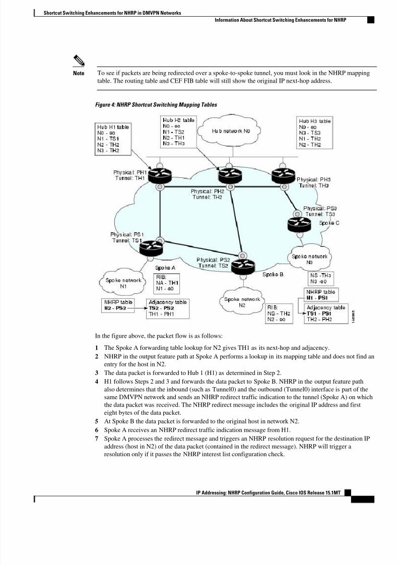
8/6/2019 Nhrp 15 1mt Book
http://slidepdf.com/reader/full/nhrp-15-1mt-book 44/51
Note To see if packets are being redirected over a spoke-to-spoke tunnel, you must look in the NHRP mapping
table. The routing table and CEF FIB table will still show the original IP next-hop address.
Figure 4: NHRP Shortcut Switching Mapping Tables
In the figure above, the packet flow is as follows:
1 The Spoke A forwarding table lookup for N2 gives TH1 as its next-hop and adjacency.
2 NHRP in the output feature path at Spoke A performs a lookup in its mapping table and does not find an
entry for the host in N2.
3 The data packet is forwarded to Hub 1 (H1) as determined in Step 2.
4 H1 follows Steps 2 and 3 and forwards the data packet to Spoke B. NHRP in the output feature path
also determines that the inbound (such as Tunnel0) and the outbound (Tunnel0) interface is part of the
same DMVPN network and sends an NHRP redirect traffic indication to the tunnel (Spoke A) on whichthe data packet was received. The NHRP redirect message includes the original IP address and first
eight bytes of the data packet.
5 At Spoke B the data packet is forwarded to the original host in network N2.
6 Spoke A receives an NHRP redirect traffic indication message from H1.
7 Spoke A processes the redirect message and triggers an NHRP resolution request for the destination IP
address (host in N2) of the data packet (contained in the redirect message). NHRP will trigger a
resolution only if it passes the NHRP interest list configuration check.
Shortcut Switching Enhancements for NHRP in DMVPN Networks
Information About Shortcut Switching Enhancements for NHRP
IP Addressing: NHRP Configuration Guide, Cisco IOS Release 15.1MT41
8/6/2019 Nhrp 15 1mt Book
http://slidepdf.com/reader/full/nhrp-15-1mt-book 45/51
8 The NHRP resolution request follows the Spoke A-Hub 1-Spoke B path. The NHRP resolution follows
the routed path towards the destination until it reaches Spoke B.
9 Spoke B routing lookup for the destination IP address (host in N2) finds that it is the exit point of the
DMVPN network.
10 Spoke B builds any IPsec tunnel required to Spoke A and sends the NHRP resolution reply directly over
the tunnel to Spoke A. The Spoke B reply contains prefix information of N2 and not just the reply forthe host in N2; that is, Spoke B indicates that not only Host B but the entire network N2 is reachable via
Spoke B. Spoke B creates a local cache entry for N2 and a list of requestors to which it has replied for
network N2.
11 Spoke A receives the reply and installs the mapping for N2 in its mapping table. Further packets for any
host in network N2 is forwarded to Spoke B directly.
NHRP Purge Request ReplyWhen an NHRP hub replies to a resolution request, it creates a local NHRP mapping entry. The local
mapping entry is a network entry for which NHRP has sent a reply. The local mapping entry maintains a
list of requestors. When a network entry is modified or deleted in the routing table, NHRP is notified of the
event. NHRP finds the local cache entry for the network and sends a purge request to the requestors that thenetwork to which it previously replied has changed. The receivers of the purge message delete the
corresponding NHRP mapping entry from its table and send a purge reply indicating that the purge
message was processed successfully.
How to Configure Shortcut Switching for NHRP
Note If ip nhrp shortcut and ip nhrp redirect are not configured, then the DMVPN network will continue to
function as it did prior to this feature.
• Enabling NHRP Shortcut Switching on an Interface, page 42
• Configuring NHRP Redirect, page 43
Enabling NHRP Shortcut Switching on an InterfacePerform this task to enable shortcut switching for NHRP for an interface on a router.
Note When using this feature, we recommend configuring the ip nhrp redirect command on all the DMVPN
nodes. This configuration would be useful in the event the data traffic takes a spoke-to-spoke-hub-spoke
path.
NHRP Purge Request Reply
How to Configure Shortcut Switching for NHRP
IP Addressing: NHRP Configuration Guide, Cisco IOS Release 15.1MT
42
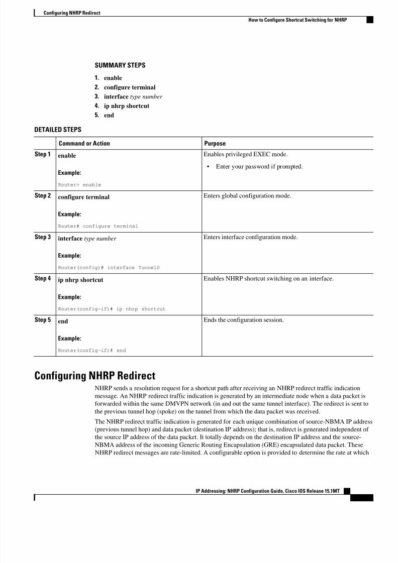
8/6/2019 Nhrp 15 1mt Book
http://slidepdf.com/reader/full/nhrp-15-1mt-book 46/51
SUMMARY STEPS
1. enable
2. configure terminal
3. interface type number 4. ip nhrp shortcut
5. end
DETAILED STEPS
Command or Action Purpose
Step 1 enable
Example:
Router> enable
Enables privileged EXEC mode.
• Enter your password if prompted.
Step 2 configure terminal
Example:
Router# configure terminal
Enters global configuration mode.
Step 3 interface type number
Example:
Router(config)# interface Tunnel0
Enters interface configuration mode.
Step 4 ip nhrp shortcut
Example:
Router(config-if)# ip nhrp shortcut
Enables NHRP shortcut switching on an interface.
Step 5 end
Example:
Router(config-if)# end
Ends the configuration session.
Configuring NHRP RedirectNHRP sends a resolution request for a shortcut path after receiving an NHRP redirect traffic indication
message. An NHRP redirect traffic indication is generated by an intermediate node when a data packet isforwarded within the same DMVPN network (in and out the same tunnel interface). The redirect is sent to
the previous tunnel hop (spoke) on the tunnel from which the data packet was received.
The NHRP redirect traffic indication is generated for each unique combination of source-NBMA IP address
(previous tunnel hop) and data packet (destination IP address); that is, redirect is generated independent of
the source IP address of the data packet. It totally depends on the destination IP address and the source-
NBMA address of the incoming Generic Routing Encapsulation (GRE) encapsulated data packet. These
NHRP redirect messages are rate-limited. A configurable option is provided to determine the rate at which
Configuring NHRP Redirect
How to Configure Shortcut Switching for NHRP
IP Addressing: NHRP Configuration Guide, Cisco IOS Release 15.1MT43
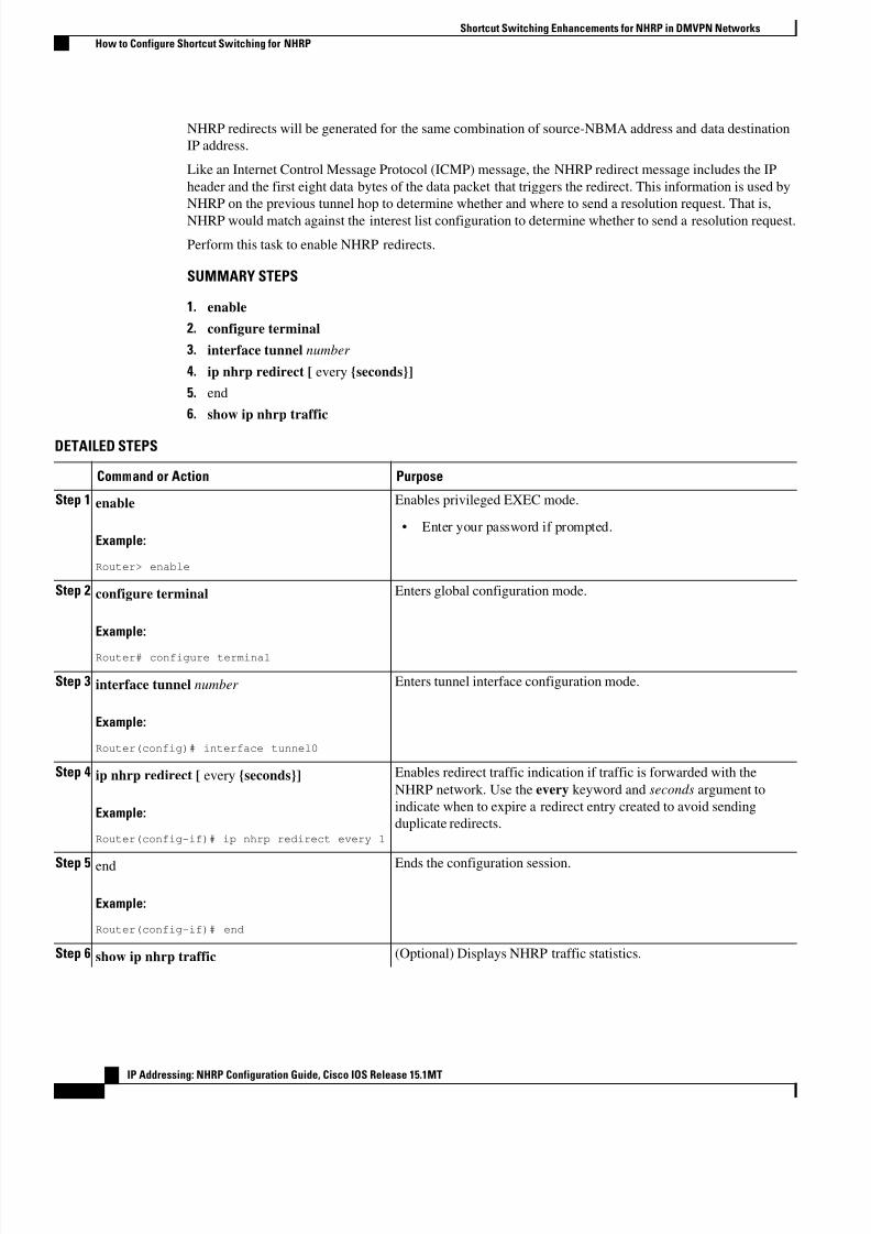
8/6/2019 Nhrp 15 1mt Book
http://slidepdf.com/reader/full/nhrp-15-1mt-book 47/51
NHRP redirects will be generated for the same combination of source-NBMA address and data destination
IP address.
Like an Internet Control Message Protocol (ICMP) message, the NHRP redirect message includes the IP
header and the first eight data bytes of the data packet that triggers the redirect. This information is used by
NHRP on the previous tunnel hop to determine whether and where to send a resolution request. That is,
NHRP would match against the interest list configuration to determine whether to send a resolution request.
Perform this task to enable NHRP redirects.
SUMMARY STEPS
1. enable
2. configure terminal
3. interface tunnel number
4. ip nhrp redirect [ every {seconds}]
5. end
6. show ip nhrp traffic
DETAILED STEPS
Command or Action Purpose
Step 1 enable
Example:
Router> enable
Enables privileged EXEC mode.
• Enter your password if prompted.
Step 2 configure terminal
Example:
Router# configure terminal
Enters global configuration mode.
Step 3 interface tunnel number
Example:
Router(config)# interface tunnel0
Enters tunnel interface configuration mode.
Step 4 ip nhrp redirect [ every {seconds}]
Example:
Router(config-if)# ip nhrp redirect every 1
Enables redirect traffic indication if traffic is forwarded with the
NHRP network. Use the every keyword and seconds argument to
indicate when to expire a redirect entry created to avoid sending
duplicate redirects.
Step 5 end
Example:
Router(config-if)# end
Ends the configuration session.
Step 6 show ip nhrp traffic (Optional) Displays NHRP traffic statistics.
Shortcut Switching Enhancements for NHRP in DMVPN Networks
How to Configure Shortcut Switching for NHRP
IP Addressing: NHRP Configuration Guide, Cisco IOS Release 15.1MT
44
8/6/2019 Nhrp 15 1mt Book
http://slidepdf.com/reader/full/nhrp-15-1mt-book 48/51
8/6/2019 Nhrp 15 1mt Book
http://slidepdf.com/reader/full/nhrp-15-1mt-book 49/51
Standards
Standard Title
No new or modified standards are supported by this
feature, and support for existing standards has not
been modified by this feature.
--
MIBs
MIB MIBs Link
None --
RFCs
RFC Title
None --
Technical Assistance
Description Link
The Cisco Support and Documentation website
provides online resources to download
documentation, software, and tools. Use these
resources to install and configure the software and
to troubleshoot and resolve technical issues with
Cisco products and technologies. Access to most
tools on the Cisco Support and Documentation
website requires a Cisco.com user ID andpassword.
http://www.cisco.com/cisco/web/support/
index.html
Feature Information for Shortcut Switching Enhancements forNHRP in DMVPN Networks
The following table provides release information about the feature or features described in this module.
This table lists only the software release that introduced support for a given feature in a given software
release train. Unless noted otherwise, subsequent releases of that software release train also support that
feature.Use Cisco Feature Navigator to find information about platform support and Cisco software image support.
To access Cisco Feature Navigator, go to www.cisco.com/go/cfn. An account on Cisco.com is not required.
Shortcut Switching Enhancements for NHRP in DMVPN Networks
Feature Information for Shortcut Switching Enhancements for NHRP in DMVPN Networks
IP Addressing: NHRP Configuration Guide, Cisco IOS Release 15.1MT
46
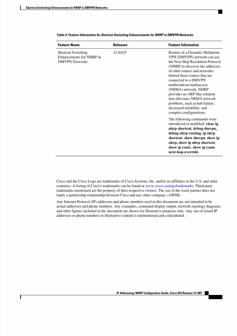
8/6/2019 Nhrp 15 1mt Book
http://slidepdf.com/reader/full/nhrp-15-1mt-book 50/51
Table 2: Feature Information for Shortcut Switching Enhancements for NHRP in DMVPN Networks
Feature Name Releases Feature Information
Shortcut Switching
Enhancements for NHRP inDMVPN Networks
12.4(6)T Routers in a Dynamic Multipoint
VPN (DMVPN) network can usethe Next Hop Resolution Protocol
(NHRP) to discover the addresses
of other routers and networks
behind those routers that are
connected to a DMVPN
nonbroadcast multiaccess
(NBMA) network. NHRP
provides an ARP-like solution
that alleviates NBMA network
problems, such as hub failure,
decreased reliability, and
complex configurations.
The following commands were
introduced or modified: clear ip
nhrp shortcut, debug dmvpn,
debug nhrp routing, ip nhrp
shortcut, show dmvpn, show ip
nhrp, show ip nhrp shortcut,
show ip route, show ip route
next-hop-override.
Cisco and the Cisco Logo are trademarks of Cisco Systems, Inc. and/or its affiliates in the U.S. and other
countries. A listing of Cisco's trademarks can be found at www.cisco.com/go/trademarks. Third party
trademarks mentioned are the property of their respective owners. The use of the word partner does not
imply a partnership relationship between Cisco and any other company. (1005R)
Any Internet Protocol (IP) addresses and phone numbers used in this document are not intended to be
actual addresses and phone numbers. Any examples, command display output, network topology diagrams,
and other figures included in the document are shown for illustrative purposes only. Any use of actual IP
addresses or phone numbers in illustrative content is unintentional and coincidental.
Shortcut Switching Enhancements for NHRP in DMVPN Networks
IP Addressing: NHRP Configuration Guide, Cisco IOS Release 15.1MT47

8/6/2019 Nhrp 15 1mt Book
http://slidepdf.com/reader/full/nhrp-15-1mt-book 51/51
Configuring NHRP Shortcut Switching and NHRP Redirect Example


![Biophysical Mechanisms of Genetic Regulation › images › PDF › Biophysical...[6], extremely-low frequency EMFs (0.1-1mT, 50Hz) applied continuously for 48-72 hrs resulted in increased](https://img.pdfslide.us/doc/110x75/5f1f4e9b1bc60321671e6ea0/biophysical-mechanisms-of-genetic-regulation-a-images-a-pdf-a-biophysical.jpg)
![OMEDIANTES REVISTACONMEMORATIVA C DE IERRA [5AÑOS] T 1MT - Otoño del … enlazados/Revista... · 2009. 2. 25. · del Pérez Alonso de poner en escena “Tres Sombreros de copa”](https://img.pdfslide.us/doc/110x75/607d084fa886427ddc7ffdff/omediantes-revistaconmemorativa-c-de-ierra-5aos-t-1mt-otoo-del-enlazadosrevista.jpg)