Embed Size (px)
Citation preview

NHD-4.3-480272EF-ASXN#-T TFT (Thin-Film-Transistor) Color Liquid Crystal Display Module
NHD- Newhaven Display 4.3- 4.3” Diagonal 480272- 480xRGBx272 Pixels EF- Model A- Built-in Driver / No Controller S- Sunlight Readable X- TFT N- TN, Wide Temperature #- RoHS Compliant T- 4-wire Resistive Touch Panel
Newhaven Display International, Inc.
2661 Galvin Ct. Elgin IL, 60124
Ph: 847-844-8795 Fax: 847-844-8796
www.newhavendisplay.com [email protected] [email protected]

[2]
Document Revision History Revision Date Description Changed by
0 9/22/15 Initial Release SB 1 1/13/17 Mechanical Drawing, Electrical & Optical Char. Updated SB 2 5/2/17 Driver IC Updated SB
Functions and Features • 480xRGBx272 resolution, up to 16.7M colors • 16-LED backlight • 24 bit RGB interface • 4-wire Resistive touch panel • Sunlight Readable

PROPRIETARY1 2 3 4 5 6
A
B
C
D
B
C
D
1 2 3 4 5 6
Mechanical Drawing
A
[3]The information contained herein is the exclusive property of Newhaven Display International, Inc. and shall not be copied, reproduced, and/or disclosed in any format without permission.
NHD-4.3-480272EF-ASXN#-T05/02/17Date
Unit
Part Number:
mmGen. Tol.
±0.3
Rev Description Date
1. Display Size: 4.3” TFT2. Optimal View: 6:003. Display Mode: Transmissive / Normally White / Anti-Glare4. Driver IC: ST7282T2 5. Supply Voltage: 3.3 V6. Backlight: White LED / 40 mA / 25.6V(Typ)7. Brightness: 780 cd/m² (Typ)8. Touch Panel: 4-Wire Resistive
Newhaven DisplayNHD-4.3-480272EF-ASXN#-T_revA
5.0±
0.5
45.6±0.5
25.2
2±0.
5
4.15±0.25
0.3±0.05
Cont
act S
ide
Stiffe
ner
95.04 (LCD AA)
105.5±0.2
5.23
53.8
6 (L
CD A
A)4.
18
67.2
±0.2
45.6
7 ±0
.5
20.5±0.218.75±0.5
20.3
5
31.1
1
52.75
98.7±0.2 (Bezel Opening)
57±0
.2 (B
ezel
Ope
ning
)
3.4±0.2
3±0.
2
Insulating Tape
98.0 (Top Polarizer)
56.2
(Top
Pol
ariz
er)
0.4
0.35
98.7±0.2 (TP VA)
96.7 (TP AA)
104.7±0.2 (TP)
64.8
±0.2
(TP)
57.5
±0.2
(TP
VA)
55.5
(TP
AA)
4.42
3.42±0.20.42±0.2
3.02.5 Pin No. Symbol
1 LED- 2 LED+ 3 GND 4 VDD
5-12 [R0-R7] 13-20 [G0-G7] 21-28 [B0-B7]
29 GND 30 CLK 31 DISP 32 HSYNC 33 VSYNC 34 DE 35 NC 36 GND 37 XR 38 YD 39 XL 40 YU
Pin Assignment
P0.5*39 = 19.5±0.10.33.
5
0.35 1.
4
1.4
Detail A
[4]
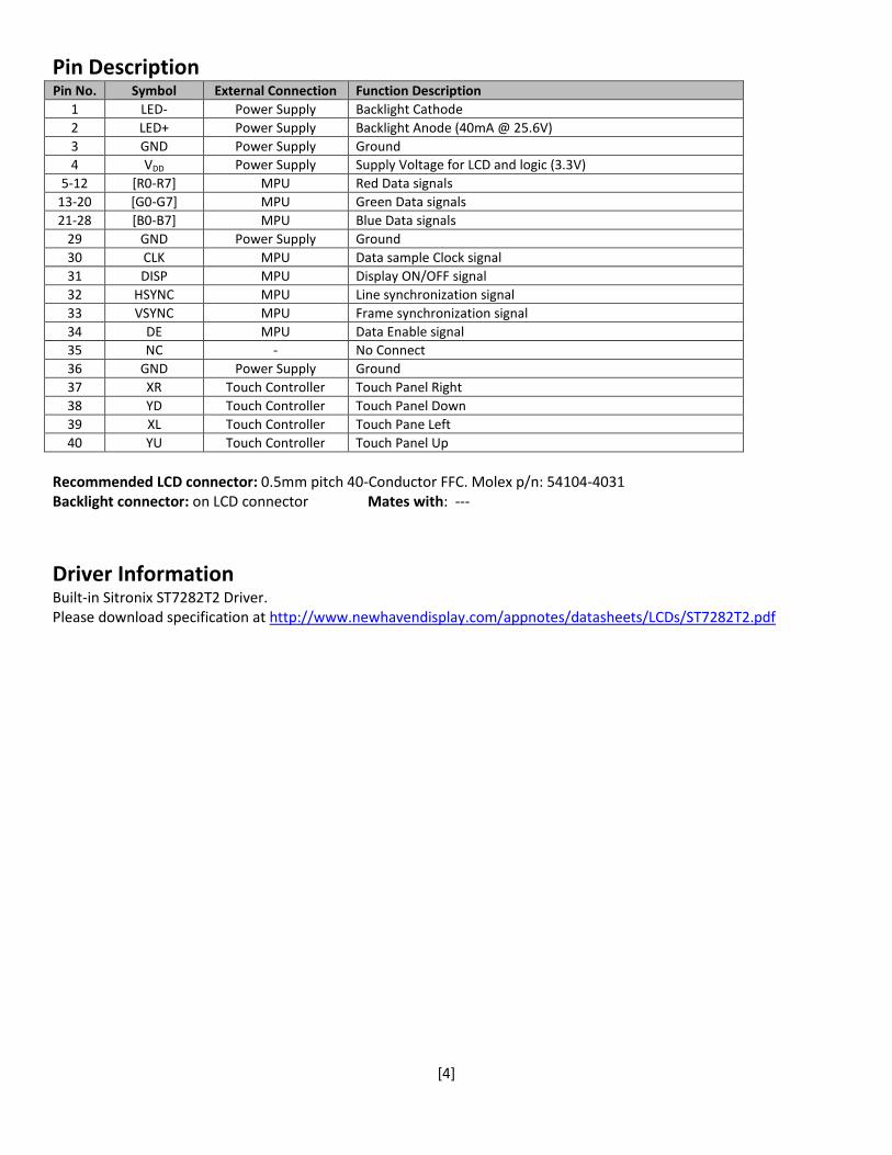
Pin Description Pin No. Symbol External Connection Function Description
1 LED- Power Supply Backlight Cathode 2 LED+ Power Supply Backlight Anode (40mA @ 25.6V) 3 GND Power Supply Ground 4 VDD Power Supply Supply Voltage for LCD and logic (3.3V)
5-12 [R0-R7] MPU Red Data signals 13-20 [G0-G7] MPU Green Data signals 21-28 [B0-B7] MPU Blue Data signals
29 GND Power Supply Ground 30 CLK MPU Data sample Clock signal 31 DISP MPU Display ON/OFF signal 32 HSYNC MPU Line synchronization signal 33 VSYNC MPU Frame synchronization signal 34 DE MPU Data Enable signal 35 NC - No Connect 36 GND Power Supply Ground 37 XR Touch Controller Touch Panel Right 38 YD Touch Controller Touch Panel Down 39 XL Touch Controller Touch Pane Left 40 YU Touch Controller Touch Panel Up
Recommended LCD connector: 0.5mm pitch 40-Conductor FFC. Molex p/n: 54104-4031 Backlight connector: on LCD connector Mates with: ---
Driver Information Built-in Sitronix ST7282T2 Driver. Please download specification at http://www.newhavendisplay.com/appnotes/datasheets/LCDs/ST7282T2.pdf
[5]
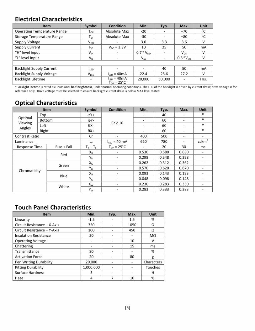
Electrical Characteristics Item Symbol Condition Min. Typ. Max. Unit
Operating Temperature Range TOP Absolute Max -20 - +70 ⁰C Storage Temperature Range TST Absolute Max -30 - +80 ⁰C Supply Voltage VDD - 3.0 3.3 3.6 V Supply Current IDD VDD = 3.3V 10 25 50 mA “H” level input VIH - 0.7 * VDD - VDD V “L” level input VIL - VSS - 0.3 *VDD V
Backlight Supply Current ILED - - 40 50 mA Backlight Supply Voltage VLED ILED = 40mA 22.4 25.6 27.2 V Backlight Lifetime - ILED = 40mA
TOP = 25°C 20,000 50,000 - Hrs.
*Backlight lifetime is rated as Hours until half-brightness, under normal operating conditions. The LED of the backlight is driven by current drain; drive voltage is for reference only. Drive voltage must be selected to ensure backlight current drain is below MAX level stated.
Optical Characteristics Item Symbol Condition Min. Typ. Max. Unit
Optimal Viewing Angles
Top ϕY+
Cr ≥ 10
- 40 - ⁰ Bottom ϕY- - 60 - ⁰ Left θX- - 60 - ⁰ Right θX+ - 60 - ⁰
Contrast Ratio Cr - 400 500 - - Luminance LV ILED = 40 mA 620 780 - cd/m2
Response Time Rise + Fall TR + TF TOP = 25°C - 20 30 ms
Chromaticity
Red XR - 0.530 0.580 0.630 - YR - 0.298 0.348 0.398 -
Green XG - 0.262 0.312 0.362 - YG - 0.570 0.620 0.670 -
Blue XB - 0.093 0.143 0.193 - YG - 0.048 0.098 0.148 -
White XW - 0.230 0.283 0.330 - YW - 0.283 0.333 0.383 -
Touch Panel Characteristics Item Min. Typ. Max. Unit
Linearity -1.5 - 1.5 % Circuit Resistance – X-Axis 350 - 1050 Ω Circuit Resistance – Y-Axis 100 - 450 Ω Insulation Resistance 20 - - MΩ Operating Voltage - - 10 V Chattering - - 15 ms Transmittance 80 - - % Activation Force 20 - 80 g Pen Writing Durability 20,000 - - Characters Pitting Durability 1,000,000 - - Touches Surface Hardness 3 - - H Haze 4 7 10 %

[6]
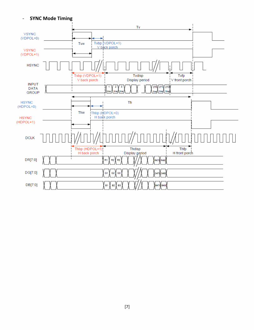
Timing Characteristics Parallel RGB input timing requirement
Item Symbol Min. Typ. Max. Unit Remark DCLK Frequency FCLK 9 12 15 MHz
DCLK Period TCLK 10 50 - µS R=10KΩ, 1µF
HSYNC
Period Time Th 485 525 532 DCLK Display Period Thdisp - 480 - DCLK Back Porch Thbp 3 43 50 DCLK By H_Blanking Setting Front Porch Thfp 2 2 2 DCLK Pulse Width Thw 1 1 1 DCLK
VSYNC
Period Time Tv 275 285 303 H Display Period Tvdisp - 272 - H Back Porch Tvbp 2 12 30 H By V_Blanking Setting Front Porch Tvfp 1 1 1 H Pulse Width Tvw 1 1 1 H
[7]
- SYNC Mode Timing
[8]
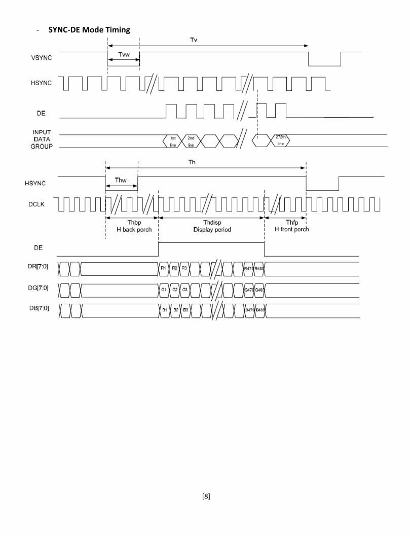
- SYNC-DE Mode Timing
[9]
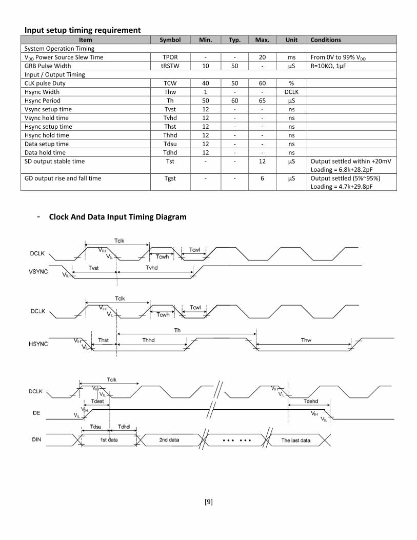
Input setup timing requirement Item Symbol Min. Typ. Max. Unit Conditions
System Operation Timing VDD Power Source Slew Time TPOR - - 20 ms From 0V to 99% VDD
GRB Pulse Width tRSTW 10 50 - µS R=10KΩ, 1µF Input / Output Timing CLK pulse Duty TCW 40 50 60 % Hsync Width Thw 1 - - DCLK Hsync Period Th 50 60 65 µS Vsync setup time Tvst 12 - - ns Vsync hold time Tvhd 12 - - ns Hsync setup time Thst 12 - - ns Hsync hold time Thhd 12 - - ns Data setup time Tdsu 12 - - ns Data hold time Tdhd 12 - - ns SD output stable time Tst - - 12 µS Output settled within +20mV
Loading = 6.8k+28.2pF GD output rise and fall time Tgst - - 6 µS Output settled (5%~95%)
Loading = 4.7k+29.8pF
- Clock And Data Input Timing Diagram

[10]
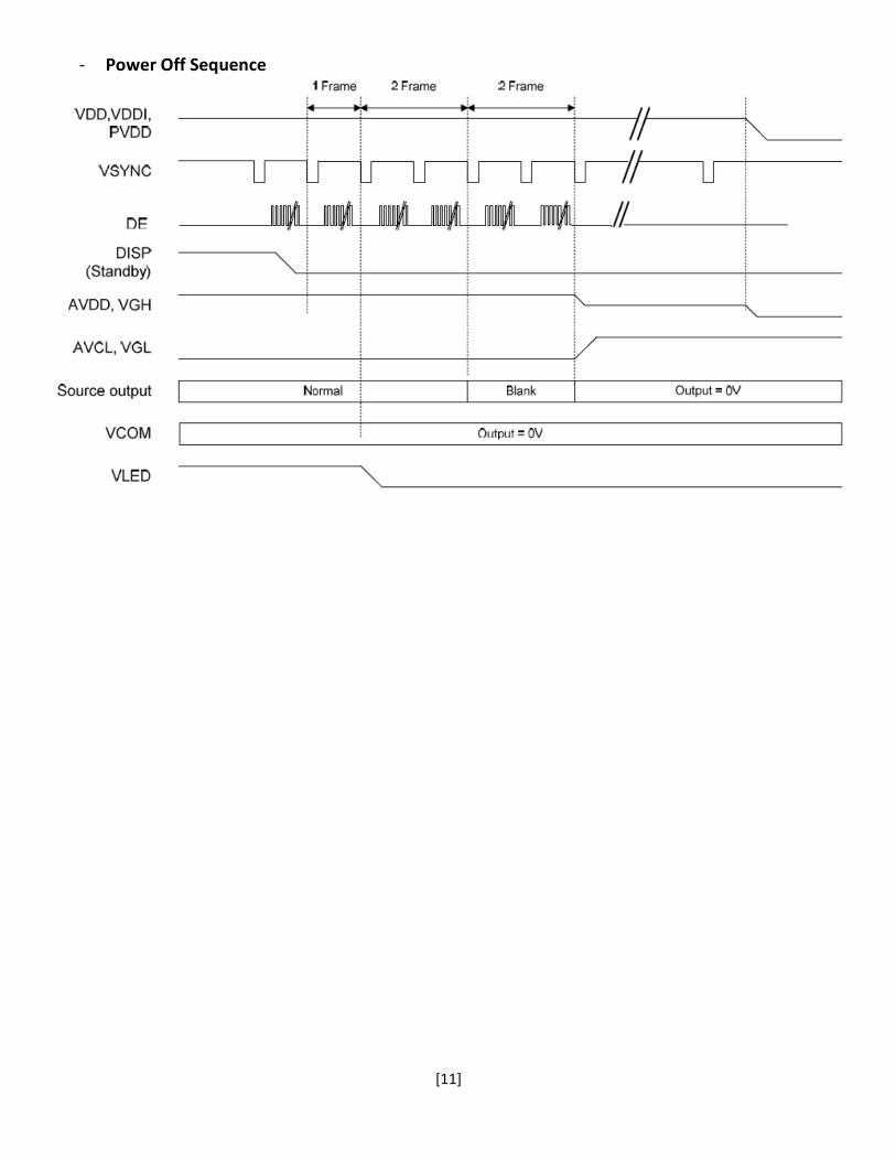
Power On/Off Sequence
- Power On Sequence
[11]
- Power Off Sequence
[12]
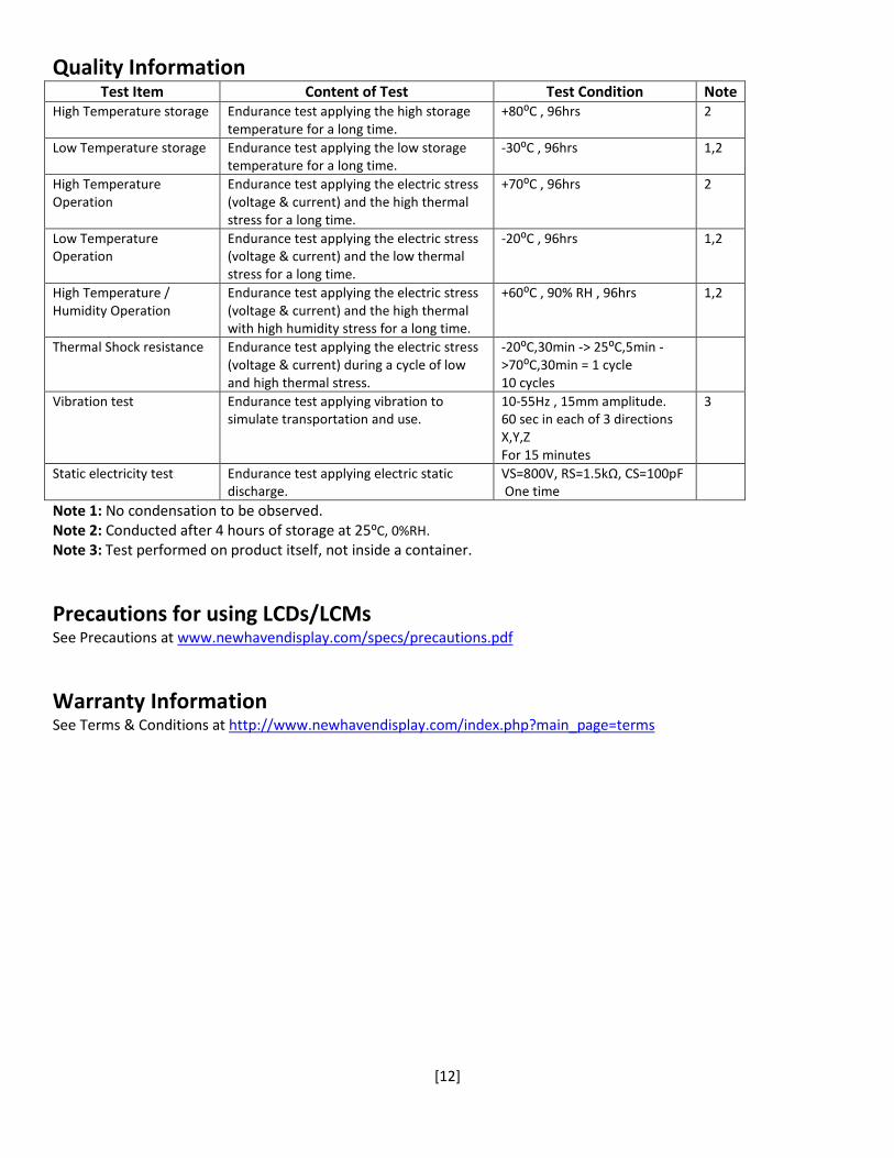
Quality Information Test Item Content of Test Test Condition Note
High Temperature storage Endurance test applying the high storage temperature for a long time.
+80⁰C , 96hrs 2
Low Temperature storage Endurance test applying the low storage temperature for a long time.
-30⁰C , 96hrs 1,2
High Temperature Operation
Endurance test applying the electric stress (voltage & current) and the high thermal stress for a long time.
+70⁰C , 96hrs 2
Low Temperature Operation
Endurance test applying the electric stress (voltage & current) and the low thermal stress for a long time.
-20⁰C , 96hrs 1,2
High Temperature / Humidity Operation
Endurance test applying the electric stress (voltage & current) and the high thermal with high humidity stress for a long time.
+60⁰C , 90% RH , 96hrs 1,2
Thermal Shock resistance Endurance test applying the electric stress (voltage & current) during a cycle of low and high thermal stress.
-20⁰C,30min -> 25⁰C,5min ->70⁰C,30min = 1 cycle 10 cycles
Vibration test Endurance test applying vibration to simulate transportation and use.
10-55Hz , 15mm amplitude. 60 sec in each of 3 directions X,Y,Z For 15 minutes
3
Static electricity test Endurance test applying electric static discharge.
VS=800V, RS=1.5kΩ, CS=100pF One time
Note 1: No condensation to be observed. Note 2: Conducted after 4 hours of storage at 25⁰C, 0%RH. Note 3: Test performed on product itself, not inside a container.
Precautions for using LCDs/LCMs See Precautions at www.newhavendisplay.com/specs/precautions.pdf
Warranty Information See Terms & Conditions at http://www.newhavendisplay.com/index.php?main_page=terms