Embed Size (px)
Citation preview
1
Bearcat Blaster
University of Cincinnati 2600 Clifton Ave, Cincinnati, OH 45220
3/28/16
Submitted by: Chris Ferguson, Chris Hinkle, Kelly Merrick, Jacob Wethington, and Jacob Wiegand
Advisor: Muthar Al-Ubaidi and Janet Dong
University of Cincinnati
NFPA 2015/2016 Chainless Challenge
Project Report
2
University of Cincinnati
College of Engineering and Applied Sciences
Mechanical Engineering Technology
Mechanical Engineering
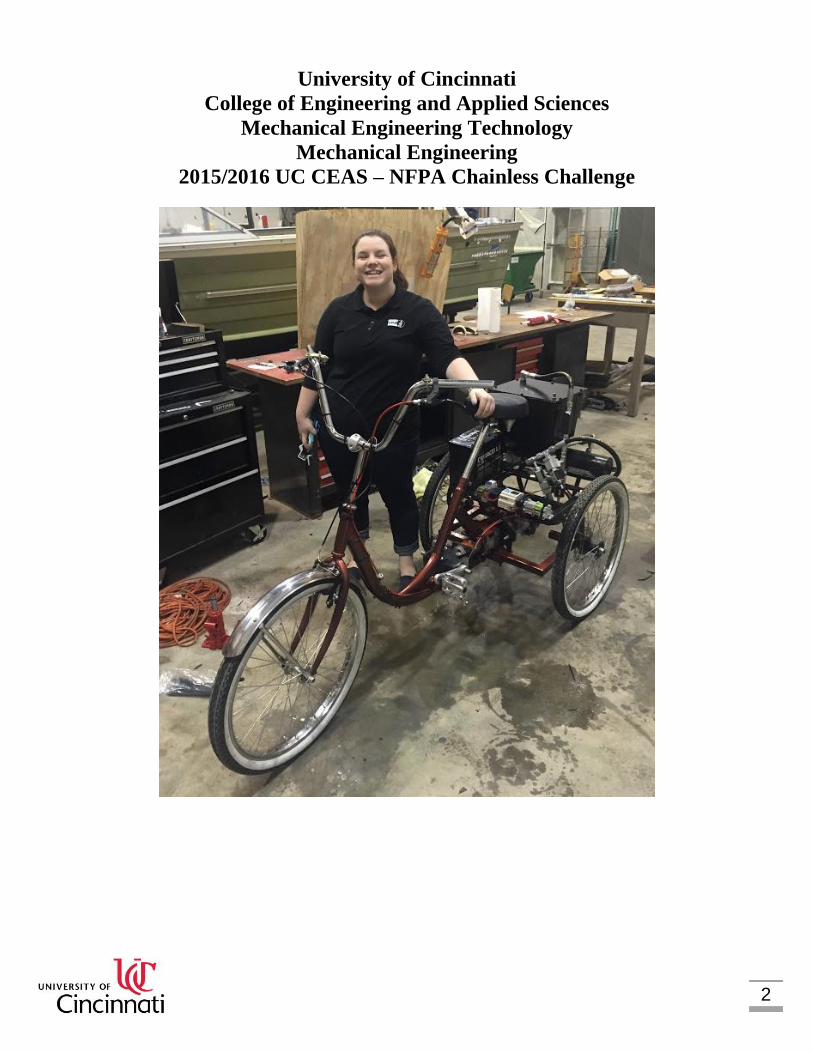
2015/2016 UC CEAS – NFPA Chainless Challenge
3
TABLE OF CONTENTS
1.0 ABSTRACT .............................................................................................................. 4
2.0 PROBLEM STATEMENT .......................................................................................... 4
3.0 PROJECT PLAN /OBJECTIVES .............................................................................. 4
3.1 OBJECTIVES ......................................................................................................... 5
4.0 DESIGN ANALYSIS .................................................................................................. 6
4.1 HYDRAULIC SYSTEM .......................................................................................... 7
4.2 VALVES ............................................................................................................... 11
4.3 FRAME, SUSPENSION, BRAKES, AND STEERING ......................................... 13
4.3.1 FRAME.......................................................................................................... 13
4.3.2 SUSPENSION ............................................................................................... 14
4.3.3 BRAKES........................................................................................................ 16
4.3.4 STEERING .................................................................................................... 17
4.4 COMPONENTS ................................................................................................... 17
4.5 DRIVE TRAIN SYSTEMS .................................................................................... 19
4.6 PAINT AND AESTHETICS .................................................................................. 21
4.7 VALVE PROGRAMMING .................................................................................... 23
5.0 DESIGN DRAWINGS .............................................................................................. 31
6.0 COMPONENT LIST ................................................................................................ 38
7.0 ACTUAL TEST DATA COMPARED TO ANALYSIS .............................................. 39
8.0 COST ANALYSIS ................................................................................................... 42
9.0 LESSONS LEARNED ............................................................................................. 46
9.1 HYDRAULIC CIRCUIT ........................................................................................ 46
9.2 OUTPUT GEAR RATIO ....................................................................................... 47
10.0 CONCLUSIONS .................................................................................................... 47

4
1.0 ABSTRACT
Every year Parker Hannifin holds the Chainless Bike Challenge. This year the University of Cincinnati will be competing among many other schools to show off their design for a hydraulically powered bike. Normally a bike is driven using a chain, which makes it very efficient and easy to manufacture. By forcing the students to use a hydraulic drive train, they will need to consider efficiency, cost, weight, and manufacturability to create a competitive bike. After designing and assembling a working bike all schools ship their bikes to California for the competition. This competition contains three different races which are; the sprint race, efficiency race, and distance race. These three races will successfully test every aspect of the bike. Each university is ranked from their scoring in each race and presentations throughout the challenge, where afterwards a school will be the victor with the best overall score. After the competition everyone will walk away with a better understanding for hydraulic power, design, and functionality.
The bicycle designed by the University of Cincinnati was a tricycle with a 10 cc motor and a 6 cc pump. The bicycle utilized solenoid valves and PLC logic to properly operate it and to properly utilize regenerative braking. There were two sets of brakes on the bike to increase the safety. The front wheel utilized a rim brake and the back utilized a disc brake. The maximum speed that the Bearcat Blaster reaches is 6 miles per hour with an average pace of 4 miles per hour. The Bearcat Blaster would cost $5,235.99 for someone to purchase.
Within this design there were a couple of things post production that could be improved upon to make the bicycle more efficient with higher speeds. Some of these things include increasing the size of the motor as well as reconfiguring the output gear ratio.
2.0 PROBLEM STATEMENT
Bicycles account for the majority of transportation vehicles throughout the world, but the traditional design of using a chain and sprocket has rarely been challenged. Through original thinking and unique innovations, a bicycle that performs well without a chain and sprocket, and instead through fluid power needed to be designed. The NFPA Chainless Challenge is a competition which encourages and challenges creative thinking where students from various colleges design and manufacture a bicycle that runs solely on hydraulic or pneumatic power. 3.0 PROJECT PLAN /OBJECTIVES
The key to a successful project is in the planning. Through analyzing the objectives, delegating responsibilities to each team member, and creating a project timeline a project plan was created.
5
The project plan to design and manufacture a hydraulic bicycle consisted of four steps. The first step was product planning. This step included product evaluations, setting product targets, writing specifications, and creating concept ideas. The second step was concept design. This step included product level simulation/ analysis and design. The fourth step was detail design. This step included the 3D model and drawings, assembly planning, cost estimating, and detailed analysis. The fourth and final step was prototype and verification. This includes building the prototypes, conducting tests, and problem solving.
In order to efficiently complete the project plan the team members focused on different aspects of the bicycle. Jacob Wiegand focused on the frame, suspension, and steering, Jacob Wethington focused on the different valves and how to properly set them up and integrate them into our system, Chris Hinkle focused on regenerative braking, and Kelly Merrick and Chris Ferguson focused on the hydraulic circuit.
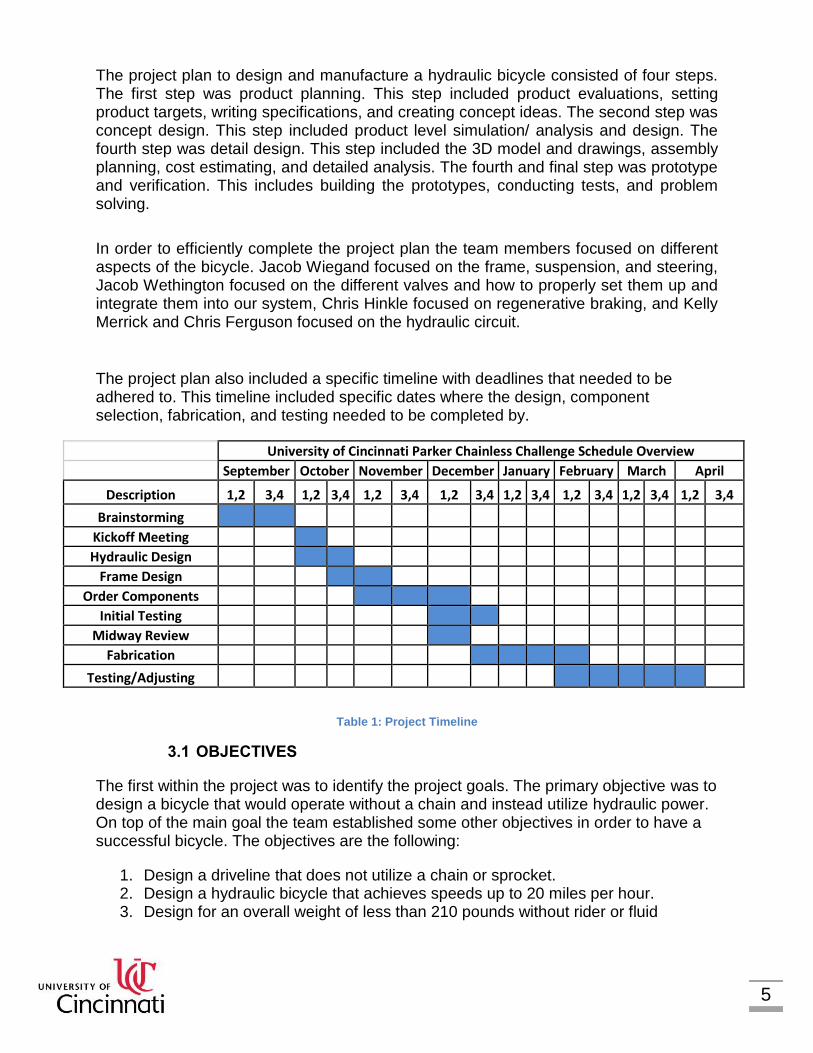
The project plan also included a specific timeline with deadlines that needed to be adhered to. This timeline included specific dates where the design, component selection, fabrication, and testing needed to be completed by.
University of Cincinnati Parker Chainless Challenge Schedule Overview
September October November December January February March April
Description 1,2 3,4 1,2 3,4 1,2 3,4 1,2 3,4 1,2 3,4 1,2 3,4 1,2 3,4 1,2 3,4
Brainstorming
Kickoff Meeting
Hydraulic Design
Frame Design
Order Components
Initial Testing
Midway Review
Fabrication
Testing/Adjusting
Table 1: Project Timeline
3.1 OBJECTIVES
The first within the project was to identify the project goals. The primary objective was to design a bicycle that would operate without a chain and instead utilize hydraulic power. On top of the main goal the team established some other objectives in order to have a successful bicycle. The objectives are the following:
1. Design a driveline that does not utilize a chain or sprocket. 2. Design a hydraulic bicycle that achieves speeds up to 20 miles per hour. 3. Design for an overall weight of less than 210 pounds without rider or fluid
6
4. Design a frame that can easily maneuver and is stable. 5. Design a braking system that utilizes regenerative braking.
4.0 DESIGN ANALYSIS
The first thing the team decided was the product targets. There were two separate goals within our bike, the first being how exactly it operated, and the second being the output. The first goal was how the bike operated. There were four situations which needed to be accounted for. These four situations included direct drive, pre-charge, discharge, regenerative braking and coasting.
7
4.1 HYDRAULIC SYSTEM
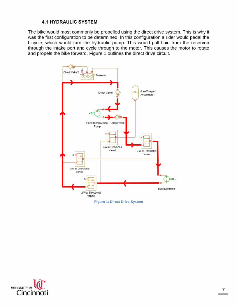
The bike would most commonly be propelled using the direct drive system. This is why it was the first configuration to be determined. In this configuration a rider would pedal the bicycle, which would turn the hydraulic pump. This would pull fluid from the reservoir through the intake port and cycle through to the motor. This causes the motor to rotate and propels the bike forward. Figure 1 outlines the direct drive circuit.
Figure 1: Direct Drive System

8
The second configuration determined was one where the team could pre-charge the bicycle. Before the race teams are allowed to manually pressurize a storage device. This storage device is known as an accumulator. When pedaling, fluid will be pulled from the reservoir to the accumulator and build up pressure in the accumulator. The accumulator charging circuit is shown in Figure 2.
Figure 2: Pre-Charged System
9
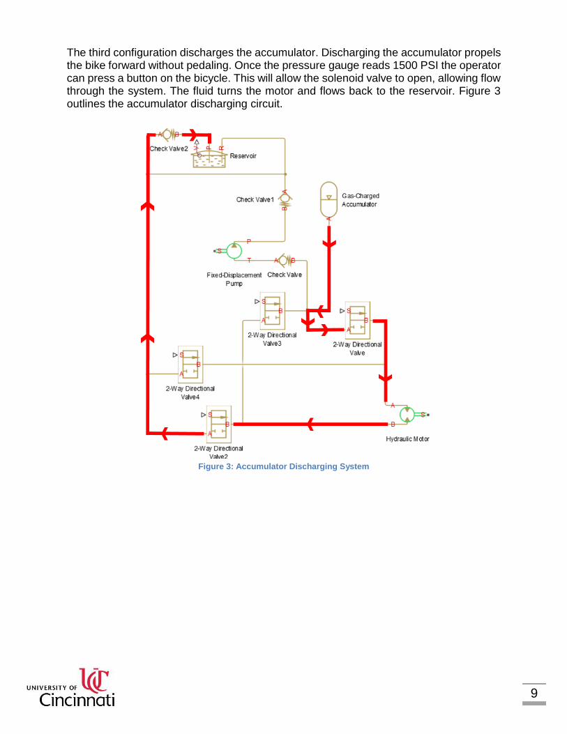
The third configuration discharges the accumulator. Discharging the accumulator propels the bike forward without pedaling. Once the pressure gauge reads 1500 PSI the operator can press a button on the bicycle. This will allow the solenoid valve to open, allowing flow through the system. The fluid turns the motor and flows back to the reservoir. Figure 3 outlines the accumulator discharging circuit.
Figure 3: Accumulator Discharging System

10
The fourth and final configuration shown in Figure 4 utilizes regenerative braking. Whenever the bike needs to slow down the regenerative braking system is useful to store the kinetic energy of the bicycle. When stopping the first check valve will close, isolating the accumulator. The motor will pull fluid from the reservoir and pump it into the accumulator using the inertia from the bike.
Figure 4: Regenerative Braking System
11
4.2 VALVES
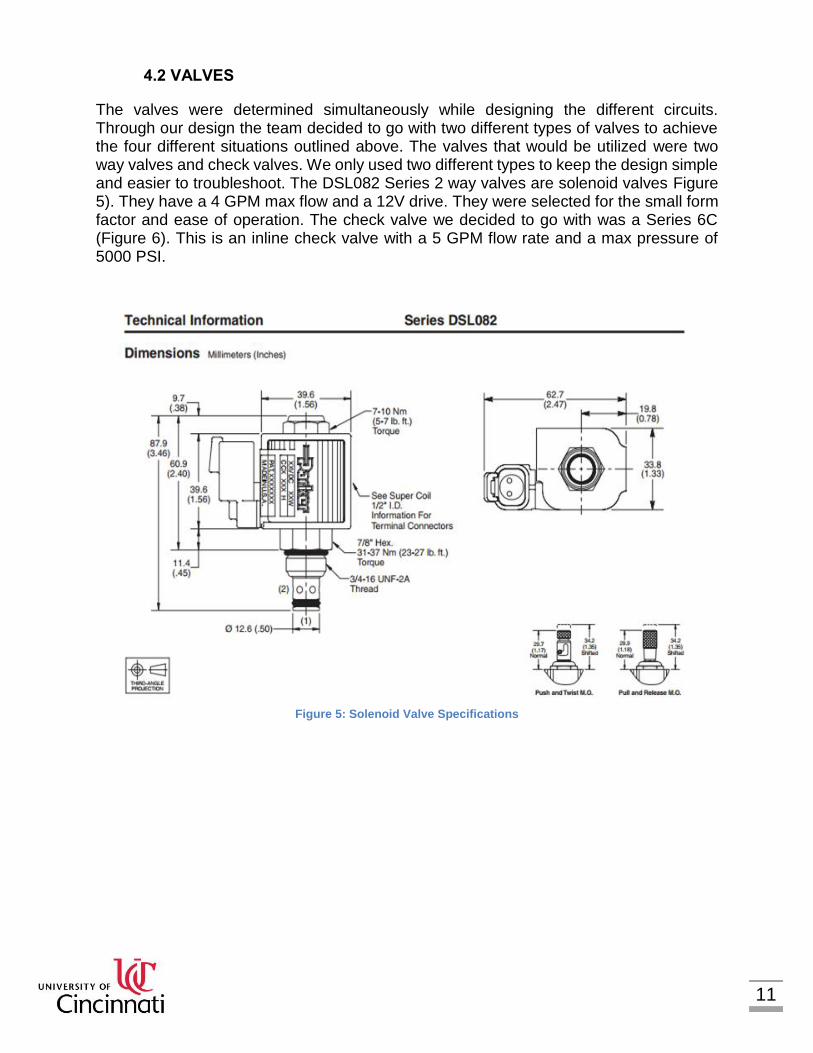
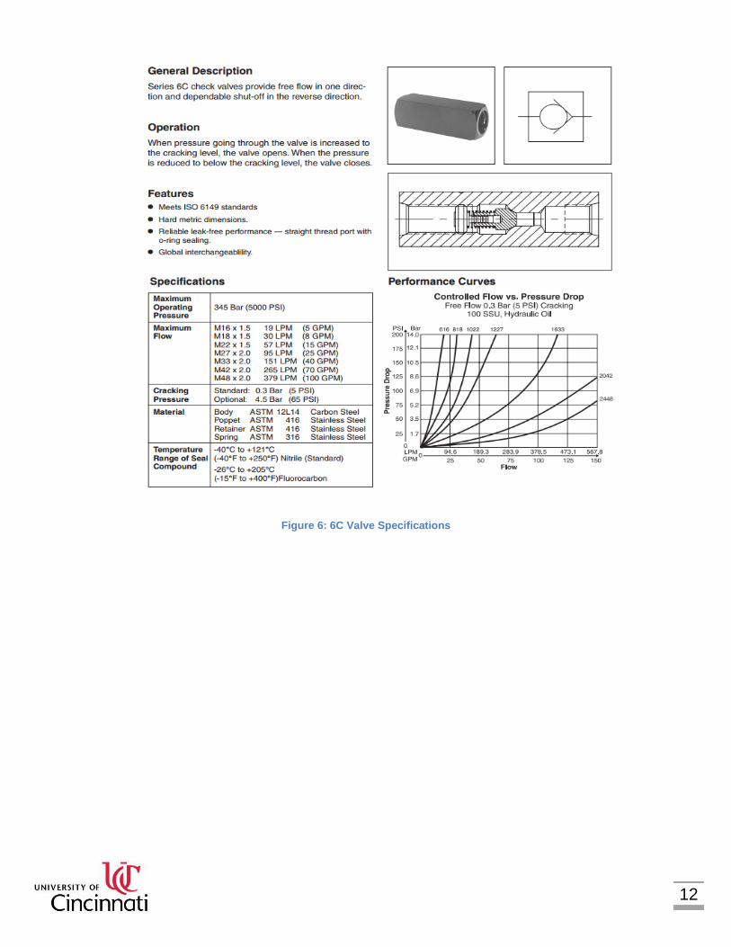
The valves were determined simultaneously while designing the different circuits. Through our design the team decided to go with two different types of valves to achieve the four different situations outlined above. The valves that would be utilized were two way valves and check valves. We only used two different types to keep the design simple and easier to troubleshoot. The DSL082 Series 2 way valves are solenoid valves Figure 5). They have a 4 GPM max flow and a 12V drive. They were selected for the small form factor and ease of operation. The check valve we decided to go with was a Series 6C (Figure 6). This is an inline check valve with a 5 GPM flow rate and a max pressure of 5000 PSI.
Figure 5: Solenoid Valve Specifications
12
Figure 6: 6C Valve Specifications
13
4.3 FRAME, SUSPENSION, BRAKES, AND STEERING
For our bicycle there were several different configurations taken into consideration. Of those considerations we strategically mapped out all the pros and cons of each configuration and were able to devise a specific arrangement that would accomplish our goals.
4.3.1 FRAME
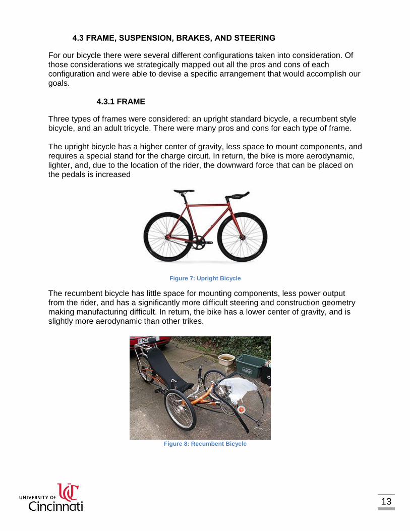
Three types of frames were considered: an upright standard bicycle, a recumbent style bicycle, and an adult tricycle. There were many pros and cons for each type of frame. The upright bicycle has a higher center of gravity, less space to mount components, and requires a special stand for the charge circuit. In return, the bike is more aerodynamic, lighter, and, due to the location of the rider, the downward force that can be placed on the pedals is increased
Figure 7: Upright Bicycle
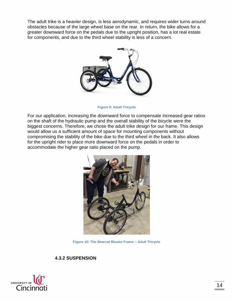
The recumbent bicycle has little space for mounting components, less power output from the rider, and has a significantly more difficult steering and construction geometry making manufacturing difficult. In return, the bike has a lower center of gravity, and is slightly more aerodynamic than other trikes.
Figure 8: Recumbent Bicycle
14
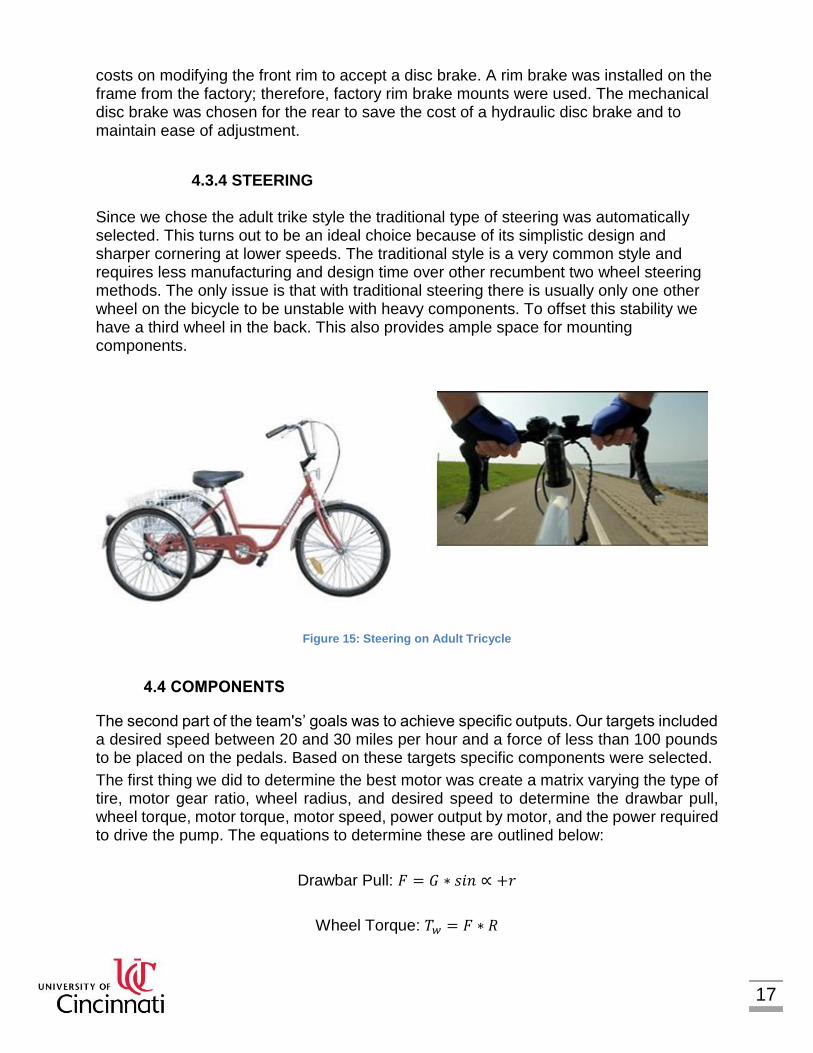
The adult trike is a heavier design, is less aerodynamic, and requires wider turns around obstacles because of the large wheel base on the rear. In return, the bike allows for a greater downward force on the pedals due to the upright position, has a lot real estate for components, and due to the third wheel stability is less of a concern.
Figure 9: Adult Tricycle
For our application, increasing the downward force to compensate increased gear ratios on the shaft of the hydraulic pump and the overall stability of the bicycle were the biggest concerns. Therefore, we chose the adult trike design for our frame. This design would allow us a sufficient amount of space for mounting components without compromising the stability of the bike due to the third wheel in the back. It also allows for the upright rider to place more downward force on the pedals in order to accommodate the higher gear ratio placed on the pump.
Figure 10: The Bearcat Blaster Frame – Adult Tricycle
4.3.2 SUSPENSION

15
Two types of suspension were taken into consideration: fork suspension and coil shock suspension. Fork suspension is used for the front and is adjustable in length and has adjustable stiffness and rebound. Coil shock suspension is used for the rear and has shorter travel, higher stiffness, and can be mounted in multiple configurations.
Figure 11: Coil Shock Suspension
Figure 12: Fork Suspension
We chose to omit suspension from our design because the conditions of the competition. The competition is held at an airport where the ground is flat and little to no bumps or rough terrain will be encountered.

16
4.3.3 BRAKES
Three types of brakes were taken into consideration: mechanical disc brakes, rim brakes, and hydraulic disc brakes. Each set has its own pros and cons. Rim brakes have a higher braking force but, the heat from the brake can warp the tire and they are more likely to be affected by debris or water. Hydraulic disc brakes have a lower braking force than rim brakes but, due to their hydraulic nature they are very strong and stop the bike quickly. They are also less dependent on the rim to be straight and are less likely to be affected by water and debris. Mechanical disc brakes have the same benefits as hydraulic brakes but, cost less and are easier to maintain or adjust.
Figure 13: Rim Brake
Figure 14: Mechanical Disc Brake
For our design we chose a mechanical disc brake for the back and a front rim brake for the front. The competition guidelines mentioned we must have at least two working brakes. Therefore, we chose to only have one in the front and one in the back, which allowed us to save some weight. The rim brake was chosen for the front in order to save
17
costs on modifying the front rim to accept a disc brake. A rim brake was installed on the frame from the factory; therefore, factory rim brake mounts were used. The mechanical disc brake was chosen for the rear to save the cost of a hydraulic disc brake and to maintain ease of adjustment.
4.3.4 STEERING
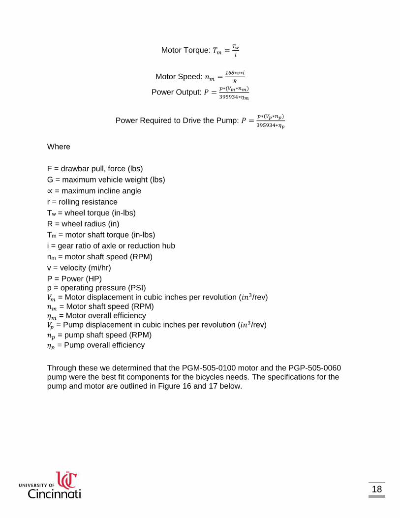
Since we chose the adult trike style the traditional type of steering was automatically selected. This turns out to be an ideal choice because of its simplistic design and sharper cornering at lower speeds. The traditional style is a very common style and requires less manufacturing and design time over other recumbent two wheel steering methods. The only issue is that with traditional steering there is usually only one other wheel on the bicycle to be unstable with heavy components. To offset this stability we have a third wheel in the back. This also provides ample space for mounting components.
Figure 15: Steering on Adult Tricycle
4.4 COMPONENTS
The second part of the team's’ goals was to achieve specific outputs. Our targets included a desired speed between 20 and 30 miles per hour and a force of less than 100 pounds to be placed on the pedals. Based on these targets specific components were selected.
The first thing we did to determine the best motor was create a matrix varying the type of tire, motor gear ratio, wheel radius, and desired speed to determine the drawbar pull, wheel torque, motor torque, motor speed, power output by motor, and the power required to drive the pump. The equations to determine these are outlined below:
Drawbar Pull: 𝐹 = 𝐺 ∗ 𝑠𝑖𝑛 ∝ +𝑟
Wheel Torque: 𝑇𝑤 = 𝐹 ∗ 𝑅
18
Motor Torque: 𝑇𝑚 =𝑇𝑤
𝑖
Motor Speed: 𝑛𝑚 =168∗𝑣∗𝑖
𝑅
Power Output: 𝑃 =𝑝∗(𝑉𝑚∗𝑛𝑚)
395934∗𝜂𝑚
Power Required to Drive the Pump: 𝑃 =𝑝∗(𝑉𝑝∗𝑛𝑝)
395934∗𝜂𝑝
Where
F = drawbar pull, force (lbs)
G = maximum vehicle weight (lbs)
∝ = maximum incline angle
r = rolling resistance
Tw = wheel torque (in-lbs)
R = wheel radius (in)
Tm = motor shaft torque (in-lbs)
i = gear ratio of axle or reduction hub
nm = motor shaft speed (RPM)
v = velocity (mi/hr)
P = Power (HP) p = operating pressure (PSI)
𝑉𝑚 = Motor displacement in cubic inches per revolution (𝑖𝑛3/rev)
𝑛𝑚 = Motor shaft speed (RPM) 𝜂𝑚 = Motor overall efficiency 𝑉𝑝 = Pump displacement in cubic inches per revolution (𝑖𝑛3/rev)
𝑛𝑝 = pump shaft speed (RPM)
𝜂𝑝 = Pump overall efficiency
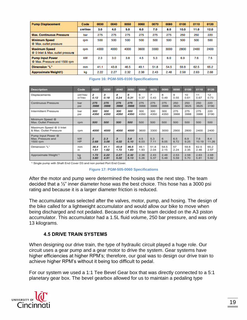
Through these we determined that the PGM-505-0100 motor and the PGP-505-0060 pump were the best fit components for the bicycles needs. The specifications for the pump and motor are outlined in Figure 16 and 17 below.
19
Figure 16: PGM-505-0100 Specifications
Figure 17: PGM-505-0060 Specifications
After the motor and pump were determined the hosing was the next step. The team decided that a ½” inner diameter hose was the best choice. This hose has a 3000 psi rating and because it is a larger diameter friction is reduced. The accumulator was selected after the valves, motor, pump, and hosing. The design of the bike called for a lightweight accumulator and would allow our bike to move when being discharged and not pedaled. Because of this the team decided on the A3 piston accumulator. This accumulator had a 1.5L fluid volume, 250 bar pressure, and was only 13 kilograms.
4.5 DRIVE TRAIN SYSTEMS
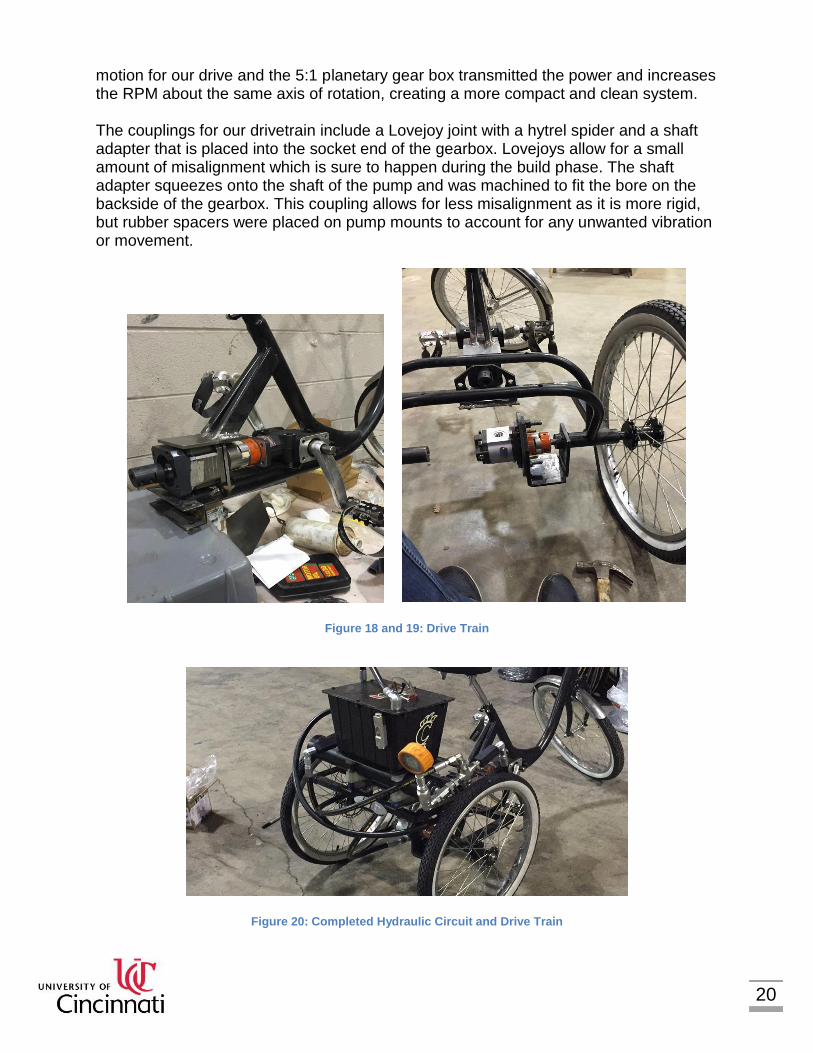
When designing our drive train, the type of hydraulic circuit played a huge role. Our circuit uses a gear pump and a gear motor to drive the system. Gear systems have higher efficiencies at higher RPM’s; therefore, our goal was to design our drive train to achieve higher RPM’s without it being too difficult to pedal. For our system we used a 1:1 Tee Bevel Gear box that was directly connected to a 5:1 planetary gear box. The bevel gearbox allowed for us to maintain a pedaling type
20
motion for our drive and the 5:1 planetary gear box transmitted the power and increases the RPM about the same axis of rotation, creating a more compact and clean system. The couplings for our drivetrain include a Lovejoy joint with a hytrel spider and a shaft adapter that is placed into the socket end of the gearbox. Lovejoys allow for a small amount of misalignment which is sure to happen during the build phase. The shaft adapter squeezes onto the shaft of the pump and was machined to fit the bore on the backside of the gearbox. This coupling allows for less misalignment as it is more rigid, but rubber spacers were placed on pump mounts to account for any unwanted vibration or movement.
Figure 18 and 19: Drive Train
Figure 20: Completed Hydraulic Circuit and Drive Train
21
4.6 PAINT AND AESTHETICS
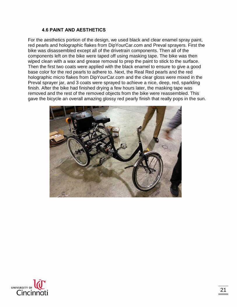
For the aesthetics portion of the design, we used black and clear enamel spray paint, red pearls and holographic flakes from DipYourCar.com and Preval sprayers. First the bike was disassembled except all of the drivetrain components. Then all of the components left on the bike were taped off using masking tape. The bike was then wiped clean with a wax and grease removal to prep the paint to stick to the surface. Then the first two coats were applied with the black enamel to ensure to give a good base color for the red pearls to adhere to. Next, the Real Red pearls and the red holographic micro flakes from DipYourCar.com and the clear gloss were mixed in the Preval sprayer jar, and 3 coats were sprayed to achieve a nice, deep, red, sparkling finish. After the bike had finished drying a few hours later, the masking tape was removed and the rest of the removed objects from the bike were reassembled. This gave the bicycle an overall amazing glossy red pearly finish that really pops in the sun.
22
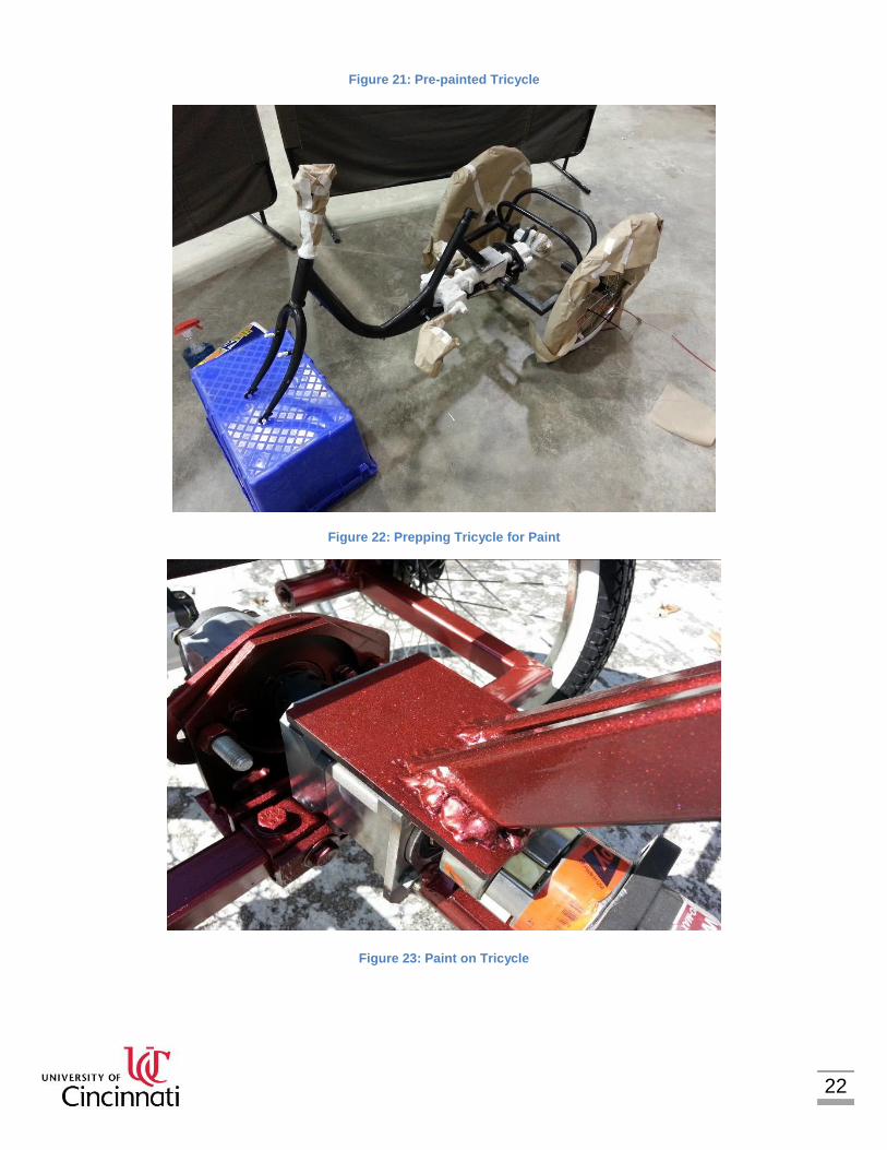
Figure 21: Pre-painted Tricycle
Figure 22: Prepping Tricycle for Paint
Figure 23: Paint on Tricycle

23
Figure 24: Finished Tricycle Fram
4.7 VALVE PROGRAMMING
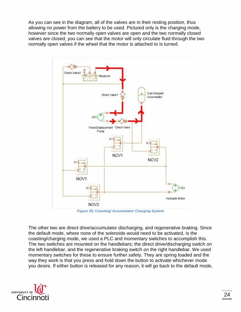
The final aspect of design analysis was how to program and control each valve to accomplish the four different scenarios. This was done using PLC programming, fuses, diodes, and a circuit breaker, all of which were 12 Volt to work with our 12 Volt battery. We have 5 different modes; accumulator charging, accumulator discharging, direct drive, coasting, and regenerative braking, however some of these modes are activated using the same valves. Accumulator charging and coasting use the same valves in the same setup just as the accumulator discharging and the direct drive modes use the same valves. This was done to cushion the fluid using the accumulator so the system does not jerk whenever you push the pedals. We determined the default mode to be the cruise/accumulator charging mode for safety and practicality. In this mode none of the valves are being used so it will not take any power from the battery to make the normally open valves closed and the normally closed valves open, thus allowing us to disconnect the battery to save power between challenges, and also allow us to be able to push the bike wherever necessary and not have to push against the motor on the wheel. This mode will allow the motor to spin freely and not take any excess forces to turn it, allowing it to move with minimal effort.
24
As you can see in the diagram, all of the valves are in their resting position, thus allowing no power from the battery to be used. Pictured only is the charging mode, however since the two normally open valves are open and the two normally closed valves are closed, you can see that the motor will only circulate fluid through the two normally open valves if the wheel that the motor is attached to is turned.
Figure 25: Coasting/ Accumulator Charging System
The other two are direct drive/accumulator discharging, and regenerative braking. Since the default mode, where none of the solenoids would need to be activated, is the coasting/charging mode, we used a PLC and momentary switches to accomplish this. The two switches are mounted on the handlebars; the direct drive/discharging switch on the left handlebar, and the regenerative braking switch on the right handlebar. We used momentary switches for these to ensure further safety. They are spring loaded and the way they work is that you press and hold down the button to activate whichever mode you desire. If either button is released for any reason, it will go back to the default mode,
25
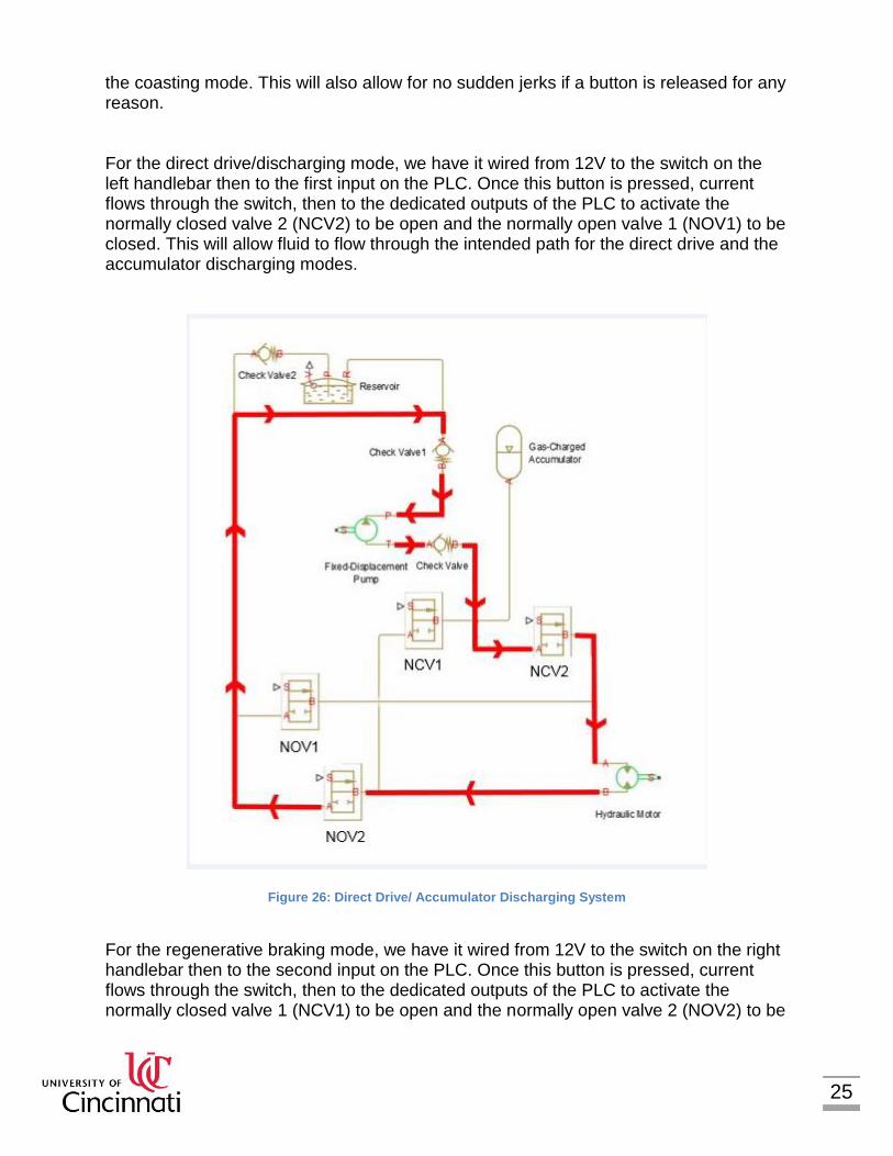
the coasting mode. This will also allow for no sudden jerks if a button is released for any reason. For the direct drive/discharging mode, we have it wired from 12V to the switch on the left handlebar then to the first input on the PLC. Once this button is pressed, current flows through the switch, then to the dedicated outputs of the PLC to activate the normally closed valve 2 (NCV2) to be open and the normally open valve 1 (NOV1) to be closed. This will allow fluid to flow through the intended path for the direct drive and the accumulator discharging modes.
Figure 26: Direct Drive/ Accumulator Discharging System
For the regenerative braking mode, we have it wired from 12V to the switch on the right handlebar then to the second input on the PLC. Once this button is pressed, current flows through the switch, then to the dedicated outputs of the PLC to activate the normally closed valve 1 (NCV1) to be open and the normally open valve 2 (NOV2) to be

26
closed. This will allow fluid to flow through the intended path for the direct drive and the accumulator discharging modes.
Figure 27: Regnerative Braking System
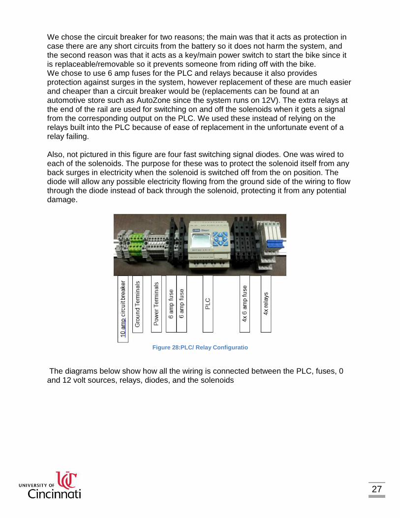
The next segment will show how the relays, fuses, and PLC all interact with each other. The PLC used was an IMO iSmart PLC which operates on 12 volts. It has 8 inputs, 2 of which are analog and 4 outputs. We used two of the normal inputs because we only had two switches and all four of the outputs because we had four solenoids. The PLC does have relays for each output built into it, however we also installed another relay on the rail for each solenoid for ease of maintenance in case one needed to be replaced, the relay on the rail can just be switched out instead of having to replace the entire PLC. All of the parts are labeled in the diagram below. As you can see, there is one 10 amp circuit breaker, four ground terminals, six power terminals, six 6 amp fuses, one PLC, and four relays. The PLC was chosen for its ease of programming (can be programmed straight on the PLC itself instead of connecting to a computer), compact size, 12V capability, and its multiple inputs and outputs.
27
We chose the circuit breaker for two reasons; the main was that it acts as protection in case there are any short circuits from the battery so it does not harm the system, and the second reason was that it acts as a key/main power switch to start the bike since it is replaceable/removable so it prevents someone from riding off with the bike. We chose to use 6 amp fuses for the PLC and relays because it also provides protection against surges in the system, however replacement of these are much easier and cheaper than a circuit breaker would be (replacements can be found at an automotive store such as AutoZone since the system runs on 12V). The extra relays at the end of the rail are used for switching on and off the solenoids when it gets a signal from the corresponding output on the PLC. We used these instead of relying on the relays built into the PLC because of ease of replacement in the unfortunate event of a relay failing. Also, not pictured in this figure are four fast switching signal diodes. One was wired to each of the solenoids. The purpose for these was to protect the solenoid itself from any back surges in electricity when the solenoid is switched off from the on position. The diode will allow any possible electricity flowing from the ground side of the wiring to flow through the diode instead of back through the solenoid, protecting it from any potential damage.
Figure 28:PLC/ Relay Configuratio
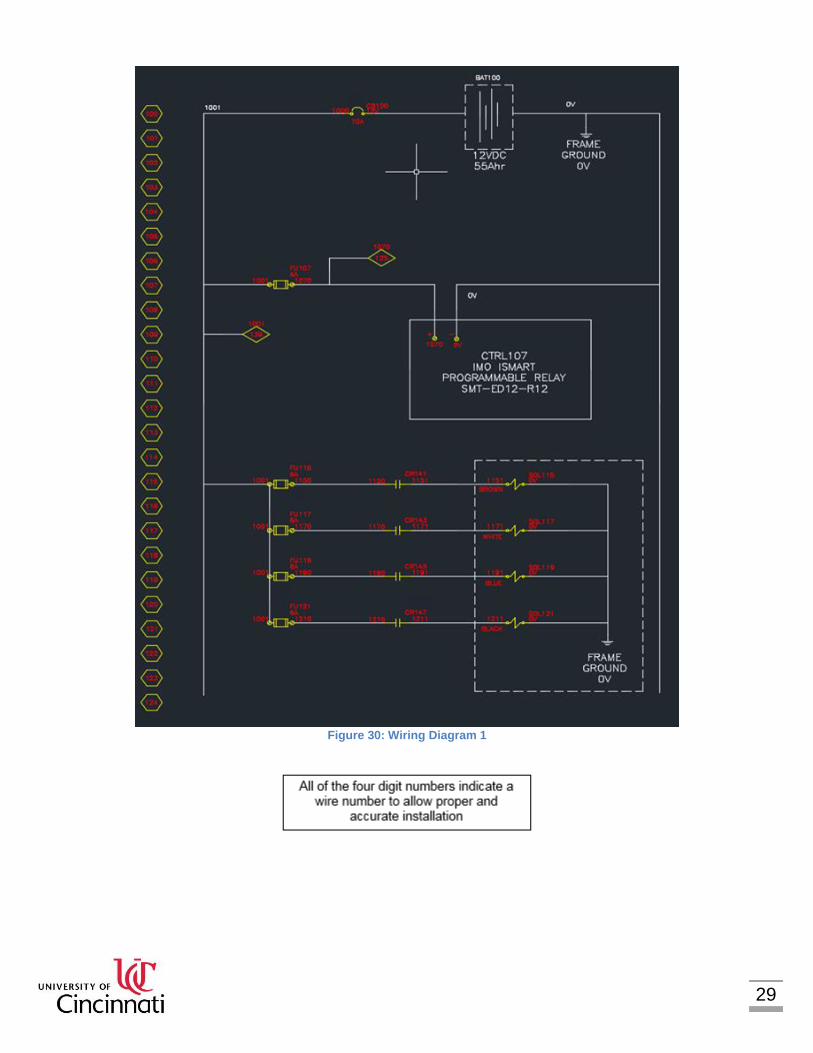
The diagrams below show how all the wiring is connected between the PLC, fuses, 0 and 12 volt sources, relays, diodes, and the solenoids

28
Table 2: Legend for Wiring Diagrams
29
Figure 30: Wiring Diagram 1

30
Figure 31: Wiring Diagram 2

31
5.0 DESIGN DRAWINGS
Below are the parts that were made by a previous team; these drawings were taken from University of Cincinnati’s 2013-2014 report, by Kyle Raabe, Paul Rose, Ryan Kirkpatrick, and Mike Bodey, to display their changes to the frame that we benefitted from:
Figure 32: Rear Frame Drawing
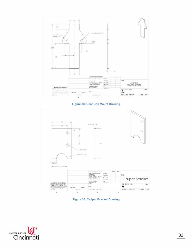
32
Figure 33: Gear Box Mount Drawing
Figure 34: Caliper Bracket Drawing
33
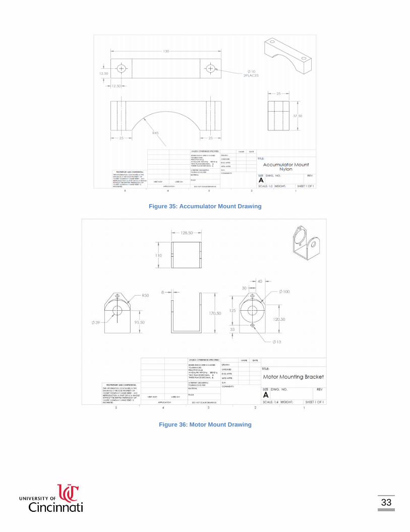
Figure 35: Accumulator Mount Drawing
Figure 36: Motor Mount Drawing
34
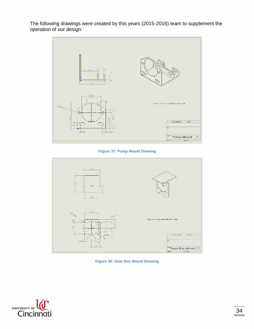
The following drawings were created by this years (2015-2016) team to supplement the operation of our design:
Figure 37: Pump Mount Drawing
Figure 38: Gear Box Mount Drawing

35
Figure 39: Motor Mount Plate Drawing
Figure 40: Frame FEA
36
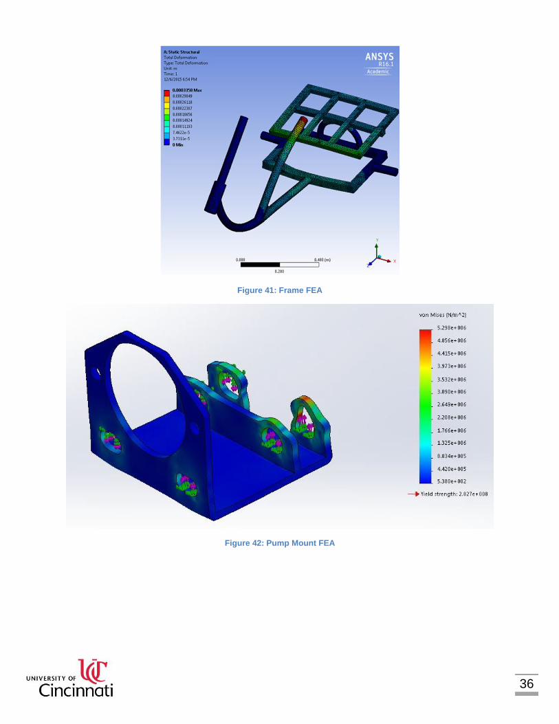
Figure 41: Frame FEA
Figure 42: Pump Mount FEA
37
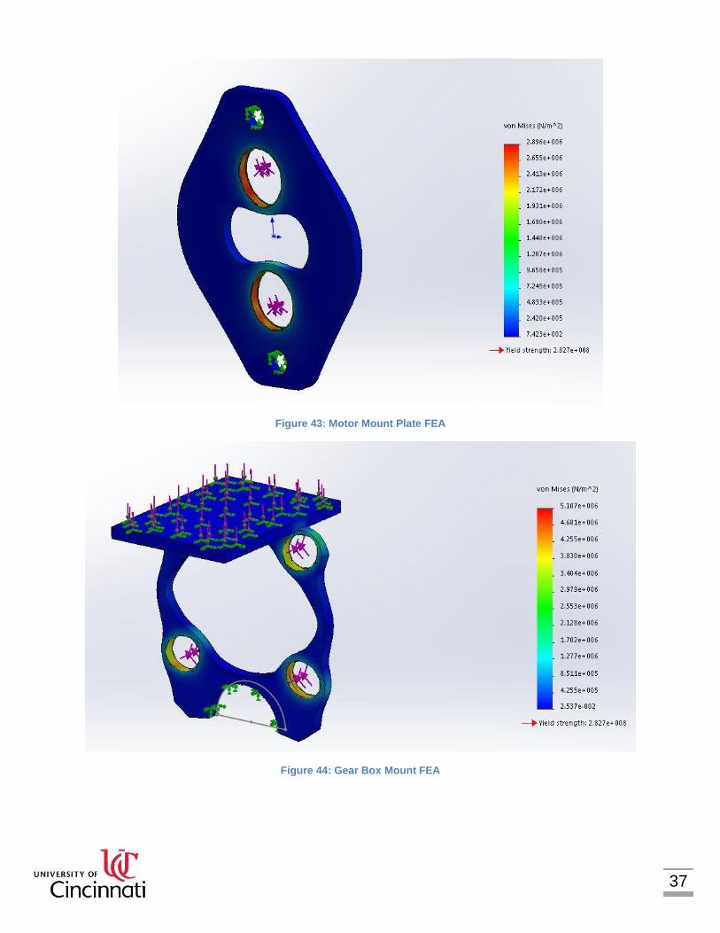
Figure 43: Motor Mount Plate FEA
Figure 44: Gear Box Mount FEA
38
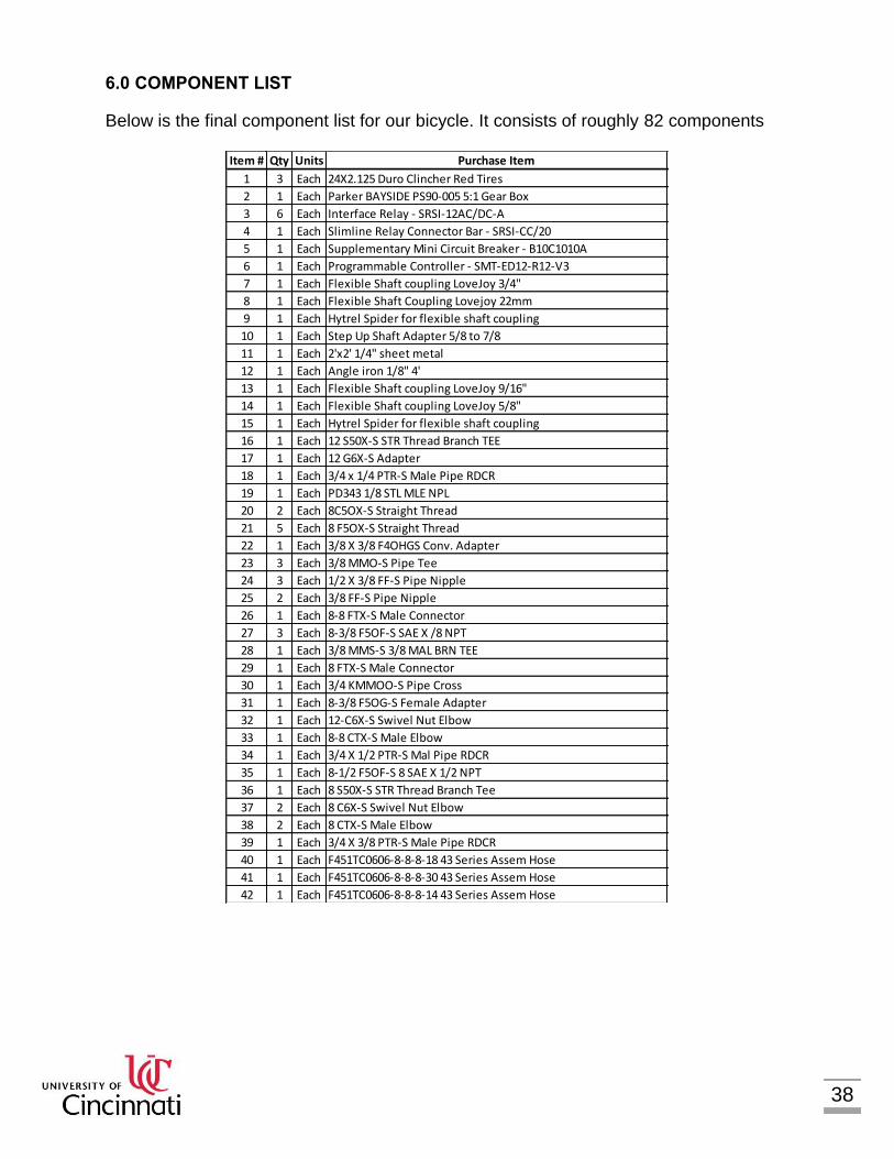
6.0 COMPONENT LIST
Below is the final component list for our bicycle. It consists of roughly 82 components
Item # Qty Units Purchase Item Cost Total Cost
1 3 Each 24X2.125 Duro Clincher Red Tires 25.67$ 77.01$
2 1 Each Parker BAYSIDE PS90-005 5:1 Gear Box 237.45$ 237.45$
3 6 Each Interface Relay - SRSI-12AC/DC-A 54.24$ 325.44$
4 1 Each Slimline Relay Connector Bar - SRSI-CC/20 1.62$ 1.62$
5 1 Each Supplementary Mini Circuit Breaker - B10C1010A 5.20$ 5.20$
6 1 Each Programmable Controller - SMT-ED12-R12-V3 101.97$ 101.97$
7 1 Each Flexible Shaft coupling LoveJoy 3/4" 20.17$ 20.17$
8 1 Each Flexible Shaft Coupling Lovejoy 22mm 20.17$ 20.17$
9 1 Each Hytrel Spider for flexible shaft coupling 55.53$ 55.53$
10 1 Each Step Up Shaft Adapter 5/8 to 7/8 57.96$ 57.96$
11 1 Each 2'x2' 1/4" sheet metal 15.02$ 15.02$
12 1 Each Angle iron 1/8" 4' 4.00$ 4.00$
13 1 Each Flexible Shaft coupling LoveJoy 9/16" 10.37$ 10.37$
14 1 Each Flexible Shaft coupling LoveJoy 5/8" 10.37$ 10.37$
15 1 Each Hytrel Spider for flexible shaft coupling 23.31$ 23.31$
16 1 Each 12 S50X-S STR Thread Branch TEE 21.16$ 21.16$
17 1 Each 12 G6X-S Adapter 12.26$ 12.26$
18 1 Each 3/4 x 1/4 PTR-S Male Pipe RDCR 2.45$ 2.45$
19 1 Each PD343 1/8 STL MLE NPL 6.22$ 6.22$
20 2 Each 8C5OX-S Straight Thread 6.74$ 13.47$
21 5 Each 8 F5OX-S Straight Thread 2.17$ 10.86$
22 1 Each 3/8 X 3/8 F4OHGS Conv. Adapter 10.89$ 10.89$
23 3 Each 3/8 MMO-S Pipe Tee 6.28$ 18.85$
24 3 Each 1/2 X 3/8 FF-S Pipe Nipple 2.66$ 7.97$
25 2 Each 3/8 FF-S Pipe Nipple 1.41$ 2.82$
26 1 Each 8-8 FTX-S Male Connector 2.16$ 2.16$
27 3 Each 8-3/8 F5OF-S SAE X /8 NPT 3.45$ 10.35$
28 1 Each 3/8 MMS-S 3/8 MAL BRN TEE 8.02$ 8.02$
29 1 Each 8 FTX-S Male Connector 1.24$ 1.24$
30 1 Each 3/4 KMMOO-S Pipe Cross 25.57$ 25.57$
31 1 Each 8-3/8 F5OG-S Female Adapter 2.10$ 2.10$
32 1 Each 12-C6X-S Swivel Nut Elbow 11.37$ 11.37$
33 1 Each 8-8 CTX-S Male Elbow 6.55$ 6.55$
34 1 Each 3/4 X 1/2 PTR-S Mal Pipe RDCR 2.35$ 2.35$
35 1 Each 8-1/2 F5OF-S 8 SAE X 1/2 NPT 5.92$ 5.92$
36 1 Each 8 S50X-S STR Thread Branch Tee 9.69$ 9.69$
37 2 Each 8 C6X-S Swivel Nut Elbow 6.34$ 12.68$
38 2 Each 8 CTX-S Male Elbow 4.41$ 8.82$
39 1 Each 3/4 X 3/8 PTR-S Male Pipe RDCR 2.26$ 2.26$
40 1 Each F451TC0606-8-8-8-18 43 Series Assem Hose 21.38$ 21.38$
41 1 Each F451TC0606-8-8-8-30 43 Series Assem Hose 25.54$ 25.54$
42 1 Each F451TC0606-8-8-8-14 43 Series Assem Hose 20.13$ 20.13$
43 1 Each F451TC0606-8-8-8-28 43 Series Assem Hose 25.12$ 25.12$
44 1 Each F451TC0606-8-8-8-17 43 Series Assem Hose 21.38$ 21.38$
45 1 Each F451TC0606-8-8-8-33 43 Series Assem Hose 26.79$ 26.79$
46 1 Each V Style Front Brake, Wire, Handles, and Jacket 53.25$ 53.25$
47 1 Each Case Drain and Fittings 38.34$ 38.34$
48 1 Each 35AH Battery 74.00$ 74.00$
49 1 Each gasket maker 5.00$ 5.00$
50 1 Each PGM505A0100BK1H1ND3D3B1 B1A4 10CC Bidirectional Motor 240.81$ 240.81$
51 15 ft JSC Wire 16 AWG Red/Black Zip Power Speaker Wire 0.38$ 5.70$
52 2 Each N.O. Metal Dome Push Button Swith 3.48$ 6.96$
53 4 Each 1N914 Small Signal Fast Switching Diode 0.05$ 0.20$
54 2 Each U-Bolt 1/4 X 1-1/8 x 2 1.79$ 3.58$
55 2 Each Brass Strips 1" X 3" 1.50$ 3.00$
56 6 Each LittleFuse 6A 3AG Fast Blow Fuse 0.40$ 2.41$
57 1 Each PGM505B0600BK1H1ND3D3D3A4 Gear Motor 250.00$ 250.00$
58 1 Each A3N0116D1E 116in^3 Accumulator 184.87$ 184.87$
59 2 Each DSL102CTNSPD012LR-A8T Normally Closed Solenoid Valve 45.64$ 91.28$
60 2 Each DSL102NTNSPD012LR-A8T Normally Open Solenoid Valve 45.64$ 91.28$
61 3 Each C800S 1/2" Check Valve 31.53$ 94.59$
62 14 Each 10577-8-8 Fittings 12.10$ 169.40$
63 1 Each Frame Sun Atlas Cargo Trike 533.75$ 533.75$
64 1 Each Rear Axle 105.00$ 105.00$
65 4 Each 15mm Bearings 7.38$ 29.52$
66 1 Each Zeromax 1:1 3-Way Bevel Gear box 474.48$ 474.48$
67 1 Each 3 Gallon Hydraulic Fluid Reservoir 230.40$ 230.40$
68 3 Each Tire Tubes 5.99$ 17.97$
69 1 Each Caliper Mount Bracket Assy 37.50$ 37.50$
70 1 Each Reservoir Mount Plate 33.33$ 33.33$
71 4 Each Nylon Accumulator Brackets 16.66$ 66.64$
72 2 Hr Rear Axle Labor 60.00$ 120.00$
73 4 Each Threaded Rod For an Accumulator Assy 4.06$ 16.24$
74 6 Hr Painting Labor 60.00$ 360.00$
75 15 Hr Fabrication Labor 60.00$ 900.00$
76 6 Hr Assembly of Bicycle 60.00$ 360.00$
77 1 Each Hardware for Mounting 20.00$ 20.00$
78 1 Each Parker Service Junior 560.00$ 560.00$
79 6 Each Fuse Holder 3.90$ 23.40$
80 1 Each Din Rail 4.75$ 4.75$
81 6 Each Seperator Block 0.90$ 5.40$
82 1 Each 10A Circuit Breaker 10.00$ 10.00$

39
Table 3: Component List
7.0 ACTUAL TEST DATA COMPARED TO ANALYSIS
There were three different races that the bike was designed to excel in. The first type of race was a sprint race. This is a race where two bikes compete head to head to see which one finishes faster completing 200 meters. The second race was an efficiency challenge. This race determines which bike has the most efficient system based on the total distance traveled from the starting point in inches multiplied by the weight of the vehicle and rider divided by the gas pre charge pressure times the gas volume of
Item # Qty Units Purchase Item Cost Total Cost
1 3 Each 24X2.125 Duro Clincher Red Tires 25.67$ 77.01$
2 1 Each Parker BAYSIDE PS90-005 5:1 Gear Box 237.45$ 237.45$
3 6 Each Interface Relay - SRSI-12AC/DC-A 54.24$ 325.44$
4 1 Each Slimline Relay Connector Bar - SRSI-CC/20 1.62$ 1.62$
5 1 Each Supplementary Mini Circuit Breaker - B10C1010A 5.20$ 5.20$
6 1 Each Programmable Controller - SMT-ED12-R12-V3 101.97$ 101.97$
7 1 Each Flexible Shaft coupling LoveJoy 3/4" 20.17$ 20.17$
8 1 Each Flexible Shaft Coupling Lovejoy 22mm 20.17$ 20.17$
9 1 Each Hytrel Spider for flexible shaft coupling 55.53$ 55.53$
10 1 Each Step Up Shaft Adapter 5/8 to 7/8 57.96$ 57.96$
11 1 Each 2'x2' 1/4" sheet metal 15.02$ 15.02$
12 1 Each Angle iron 1/8" 4' 4.00$ 4.00$
13 1 Each Flexible Shaft coupling LoveJoy 9/16" 10.37$ 10.37$
14 1 Each Flexible Shaft coupling LoveJoy 5/8" 10.37$ 10.37$
15 1 Each Hytrel Spider for flexible shaft coupling 23.31$ 23.31$
16 1 Each 12 S50X-S STR Thread Branch TEE 21.16$ 21.16$
17 1 Each 12 G6X-S Adapter 12.26$ 12.26$
18 1 Each 3/4 x 1/4 PTR-S Male Pipe RDCR 2.45$ 2.45$
19 1 Each PD343 1/8 STL MLE NPL 6.22$ 6.22$
20 2 Each 8C5OX-S Straight Thread 6.74$ 13.47$
21 5 Each 8 F5OX-S Straight Thread 2.17$ 10.86$
22 1 Each 3/8 X 3/8 F4OHGS Conv. Adapter 10.89$ 10.89$
23 3 Each 3/8 MMO-S Pipe Tee 6.28$ 18.85$
24 3 Each 1/2 X 3/8 FF-S Pipe Nipple 2.66$ 7.97$
25 2 Each 3/8 FF-S Pipe Nipple 1.41$ 2.82$
26 1 Each 8-8 FTX-S Male Connector 2.16$ 2.16$
27 3 Each 8-3/8 F5OF-S SAE X /8 NPT 3.45$ 10.35$
28 1 Each 3/8 MMS-S 3/8 MAL BRN TEE 8.02$ 8.02$
29 1 Each 8 FTX-S Male Connector 1.24$ 1.24$
30 1 Each 3/4 KMMOO-S Pipe Cross 25.57$ 25.57$
31 1 Each 8-3/8 F5OG-S Female Adapter 2.10$ 2.10$
32 1 Each 12-C6X-S Swivel Nut Elbow 11.37$ 11.37$
33 1 Each 8-8 CTX-S Male Elbow 6.55$ 6.55$
34 1 Each 3/4 X 1/2 PTR-S Mal Pipe RDCR 2.35$ 2.35$
35 1 Each 8-1/2 F5OF-S 8 SAE X 1/2 NPT 5.92$ 5.92$
36 1 Each 8 S50X-S STR Thread Branch Tee 9.69$ 9.69$
37 2 Each 8 C6X-S Swivel Nut Elbow 6.34$ 12.68$
38 2 Each 8 CTX-S Male Elbow 4.41$ 8.82$
39 1 Each 3/4 X 3/8 PTR-S Male Pipe RDCR 2.26$ 2.26$
40 1 Each F451TC0606-8-8-8-18 43 Series Assem Hose 21.38$ 21.38$
41 1 Each F451TC0606-8-8-8-30 43 Series Assem Hose 25.54$ 25.54$
42 1 Each F451TC0606-8-8-8-14 43 Series Assem Hose 20.13$ 20.13$
43 1 Each F451TC0606-8-8-8-28 43 Series Assem Hose 25.12$ 25.12$
44 1 Each F451TC0606-8-8-8-17 43 Series Assem Hose 21.38$ 21.38$
45 1 Each F451TC0606-8-8-8-33 43 Series Assem Hose 26.79$ 26.79$
46 1 Each V Style Front Brake, Wire, Handles, and Jacket 53.25$ 53.25$
47 1 Each Case Drain and Fittings 38.34$ 38.34$
48 1 Each 35AH Battery 74.00$ 74.00$
49 1 Each gasket maker 5.00$ 5.00$
50 1 Each PGM505A0100BK1H1ND3D3B1 B1A4 10CC Bidirectional Motor 240.81$ 240.81$
51 15 ft JSC Wire 16 AWG Red/Black Zip Power Speaker Wire 0.38$ 5.70$
52 2 Each N.O. Metal Dome Push Button Swith 3.48$ 6.96$
53 4 Each 1N914 Small Signal Fast Switching Diode 0.05$ 0.20$
54 2 Each U-Bolt 1/4 X 1-1/8 x 2 1.79$ 3.58$
55 2 Each Brass Strips 1" X 3" 1.50$ 3.00$
56 6 Each LittleFuse 6A 3AG Fast Blow Fuse 0.40$ 2.41$
57 1 Each PGM505B0600BK1H1ND3D3D3A4 Gear Motor 250.00$ 250.00$
58 1 Each A3N0116D1E 116in^3 Accumulator 184.87$ 184.87$
59 2 Each DSL102CTNSPD012LR-A8T Normally Closed Solenoid Valve 45.64$ 91.28$
60 2 Each DSL102NTNSPD012LR-A8T Normally Open Solenoid Valve 45.64$ 91.28$
61 3 Each C800S 1/2" Check Valve 31.53$ 94.59$
62 14 Each 10577-8-8 Fittings 12.10$ 169.40$
63 1 Each Frame Sun Atlas Cargo Trike 533.75$ 533.75$
64 1 Each Rear Axle 105.00$ 105.00$
65 4 Each 15mm Bearings 7.38$ 29.52$
66 1 Each Zeromax 1:1 3-Way Bevel Gear box 474.48$ 474.48$
67 1 Each 3 Gallon Hydraulic Fluid Reservoir 230.40$ 230.40$
68 3 Each Tire Tubes 5.99$ 17.97$
69 1 Each Caliper Mount Bracket Assy 37.50$ 37.50$
70 1 Each Reservoir Mount Plate 33.33$ 33.33$
71 4 Each Nylon Accumulator Brackets 16.66$ 66.64$
72 2 Hr Rear Axle Labor 60.00$ 120.00$
73 4 Each Threaded Rod For an Accumulator Assy 4.06$ 16.24$
74 6 Hr Painting Labor 60.00$ 360.00$
75 15 Hr Fabrication Labor 60.00$ 900.00$
76 6 Hr Assembly of Bicycle 60.00$ 360.00$
77 1 Each Hardware for Mounting 20.00$ 20.00$
78 1 Each Parker Service Junior 560.00$ 560.00$
79 6 Each Fuse Holder 3.90$ 23.40$
80 1 Each Din Rail 4.75$ 4.75$
81 6 Each Seperator Block 0.90$ 5.40$
82 1 Each 10A Circuit Breaker 10.00$ 10.00$
40
storage device. The third race was a time trial race. In this race the bike needed to travel 6.2 miles.
Our analysis concluded that with 900 pounds’ total weight, a safety factor of 2, and with a human input of .5 HP that our bike would travel at a speed of 15 miles per hour with 80 pounds of force to be placed on the pedals. Our actual results were quite different.
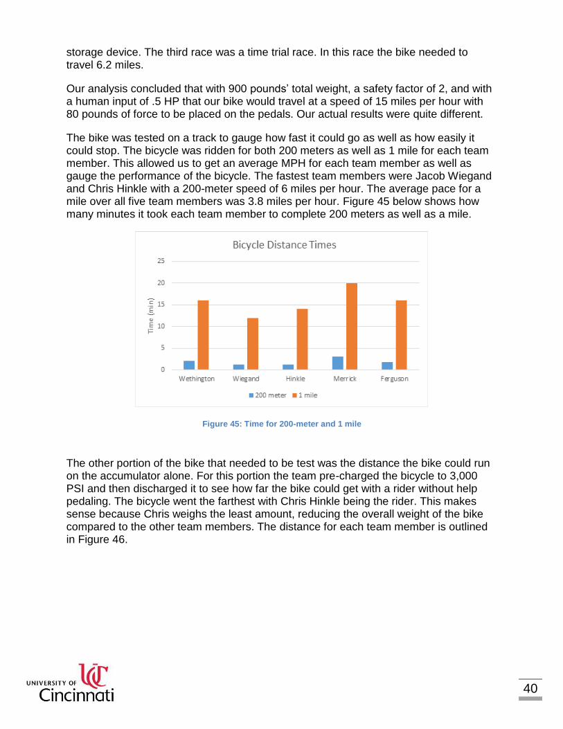
The bike was tested on a track to gauge how fast it could go as well as how easily it could stop. The bicycle was ridden for both 200 meters as well as 1 mile for each team member. This allowed us to get an average MPH for each team member as well as gauge the performance of the bicycle. The fastest team members were Jacob Wiegand and Chris Hinkle with a 200-meter speed of 6 miles per hour. The average pace for a mile over all five team members was 3.8 miles per hour. Figure 45 below shows how many minutes it took each team member to complete 200 meters as well as a mile.
Figure 45: Time for 200-meter and 1 mile
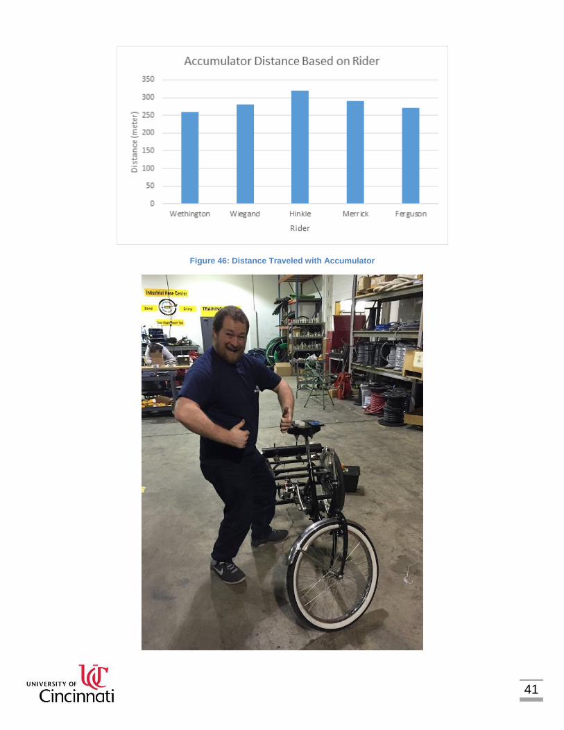
The other portion of the bike that needed to be test was the distance the bike could run on the accumulator alone. For this portion the team pre-charged the bicycle to 3,000 PSI and then discharged it to see how far the bike could get with a rider without help pedaling. The bicycle went the farthest with Chris Hinkle being the rider. This makes sense because Chris weighs the least amount, reducing the overall weight of the bike compared to the other team members. The distance for each team member is outlined in Figure 46.
41
Figure 46: Distance Traveled with Accumulator
42
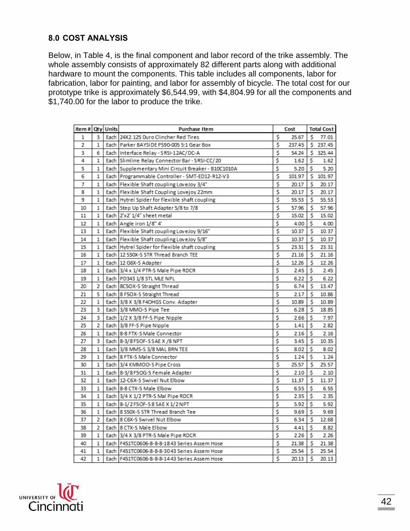
8.0 COST ANALYSIS
Below, in Table 4, is the final component and labor record of the trike assembly. The whole assembly consists of approximately 82 different parts along with additional hardware to mount the components. This table includes all components, labor for fabrication, labor for painting, and labor for assembly of bicycle. The total cost for our prototype trike is approximately $6,544.99, with $4,804.99 for all the components and $1,740.00 for the labor to produce the trike.

43
In Table 5 is the cost analysis of the trike if it was to be mass produced. The projection is for 500 units with a labor rate of approximately $60.00/ hr. For a fully automated process the costs would be cut drastically by reducing a large amount of the labor required but, for our analysis we chose to use the worst case scenario. This scenario also assumes that the manufacturing process is set up and there is proper tooling to complete all processes
Table 4: Cost Analysis

44
500 Units
Item # Units Qty Units Purchase Item Cost Wholesale Discount/
Skilled Laborer
Total Cost
Total Cost (500 Units)
1 500 3 Each 24X2.125 Duro Clincher Red Tires $25.67 20% $61.61 $30,804.00
2 500 1 Each Parker BAYSIDE PS90-005 5:1 Gear Box
$237.45 20% $189.96 $94,980.00
3 500 6 Each Interface Relay - SRSI-12AC/DC-A $54.24 20% $260.35 $130,176.00
4 500 1 Each Slimline Relay Connector Bar - SRSI-CC/20
$1.62 20% $1.30 $648.00
5 500 1 Each Supplementary Mini Circuit Breaker - B10C1010A
$5.20 20% $4.16 $2,080.00
6 500 1 Each Programmable Controller - SMT-ED12-R12-V3
$101.97 20% $81.58 $40,788.00
7 500 1 Each Flexible Shaft coupling LoveJoy 3/4" $20.17 20% $16.14 $8,068.00
8 500 1 Each Flexible Shaft Coupling Lovejoy 22mm
$20.17 20% $16.14 $8,068.00
9 500 1 Each Hytrel Spider for flexible shaft coupling
$55.53 20% $44.42 $22,212.00
10 500 1 Each Step Up Shaft Adapter 5/8 to 7/8 $57.96 20% $46.37 $23,184.00
11 500 1 Each 2'x2' 1/4" sheet metal $15.02 20% $12.02 $6,008.00
12 500 1 Each Angle iron 1/8" 4' $4.00 20% $3.20 $1,600.00
13 500 1 Each Flexible Shaft coupling LoveJoy 9/16" $10.37 20% $8.30 $4,148.00
14 500 1 Each Flexible Shaft coupling LoveJoy 5/8" $10.37 20% $8.30 $4,148.00
15 500 1 Each Hytrel Spider for flexible shaft coupling
$23.31 20% $18.65 $9,324.00
16 500 1 Each 12 S50X-S STR Thread Branch TEE $21.16 20% $16.93 $8,463.28
17 500 1 Each 12 G6X-S Adapter $12.26 20% $9.81 $4,902.80
18 500 1 Each 3/4 x 1/4 PTR-S Male Pipe RDCR $2.45 20% $1.96 $980.56
19 500 1 Each PD343 1/8 STL MLE NPL $6.22 20% $4.98 $2,488.68
20 500 2 Each 8C5OX-S Straight Thread $6.74 20% $10.78 $5,388.32
21 500 5 Each 8 F5OX-S Straight Thread $2.17 20% $8.69 $4,345.20
22 500 1 Each 3/8 X 3/8 F4OHGS Conv. Adapter $10.89 20% $8.71 $4,356.08
23 500 3 Each 3/8 MMO-S Pipe Tee $6.28 20% $15.08 $7,539.84
24 500 3 Each 1/2 X 3/8 FF-S Pipe Nipple $2.66 20% $6.37 $3,186.48
25 500 2 Each 3/8 FF-S Pipe Nipple $1.41 20% $2.25 $1,126.08
26 500 1 Each 8-8 FTX-S Male Connector $2.16 20% $1.73 $863.60
27 500 3 Each 8-3/8 F5OF-S SAE X /8 NPT $3.45 20% $8.28 $4,141.20
28 500 1 Each 3/8 MMS-S 3/8 MAL BRN TEE $8.02 20% $6.42 $3,208.24
29 500 1 Each 8 FTX-S Male Connector $1.24 20% $0.99 $495.04
30 500 1 Each 3/4 KMMOO-S Pipe Cross $25.57 20% $20.46 $10,228.56
31 500 1 Each 8-3/8 F5OG-S Female Adapter $2.10 20% $1.68 $840.48
32 500 1 Each 12-C6X-S Swivel Nut Elbow $11.37 20% $9.10 $4,549.20
33 500 1 Each 8-8 CTX-S Male Elbow $6.55 20% $5.24 $2,618.00
34 500 1 Each 3/4 X 1/2 PTR-S Mal Pipe RDCR $2.35 20% $1.88 $941.12
35 500 1 Each 8-1/2 F5OF-S 8 SAE X 1/2 NPT $5.92 20% $4.73 $2,366.40
36 500 1 Each 8 S50X-S STR Thread Branch Tee $9.69 20% $7.75 $3,876.00
37 500 2 Each 8 C6X-S Swivel Nut Elbow $6.34 20% $10.14 $5,070.08
38 500 2 Each 8 CTX-S Male Elbow $4.41 20% $7.06 $3,527.84
39 500 1 Each 3/4 X 3/8 PTR-S Male Pipe RDCR $2.26 20% $1.81 $904.40
40 500 1 Each F451TC0606-8-8-8-18 43 Series Assem Hose
$21.38 20% $17.10 $8,550.72
41 500 1 Each F451TC0606-8-8-8-30 43 Series Assem Hose
$25.54 20% $20.43 $10,215.72
42 500 1 Each F451TC0606-8-8-8-14 43 Series Assem Hose
$20.13 20% $16.10 $8,051.20
43 500 1 Each F451TC0606-8-8-8-28 43 Series Assem Hose
$25.12 20% $20.10 $10,049.20
44 500 1 Each F451TC0606-8-8-8-17 43 Series Assem Hose
$21.38 20% $17.10 $8,550.72
45 500 1 Each F451TC0606-8-8-8-33 43 Series Assem Hose
$26.79 20% $21.43 $10,715.20

45
46 500 1 Each V Style Front Brake, Wire, Handles, and Jacket
$53.25 20% $42.60 $21,300.00
47 500 1 Each Case Drain and Fittings $38.34 20% $30.67 $15,336.00
48 500 1 Each 35AH Battery $74.00 20% $59.20 $29,600.00
49 500 1 Each gasket maker $5.00 20% $4.00 $2,000.00
50 500 1 Each PGM505A0100BK1H1ND3D3B1 B1A4 10CC Bidirectional Motor
$240.81 20% $192.65 $96,324.00
51 500 15 ft JSC Wire 16 AWG Red/Black Zip Power Speaker Wire
$0.38 20% $4.56 $2,280.00
52 500 2 Each N.O. Metal Dome Push Button Swith $3.48 20% $5.57 $2,784.00
53 500 4 Each 1N914 Small Signal Fast Switching Diode
$0.05 20% $0.16 $80.00
54 500 2 Each U-Bolt 1/4 X 1-1/8 x 2 $1.79 20% $2.86 $1,432.00
55 500 2 Each Brass Strips 1" X 3" $1.50 20% $2.40 $1,200.00
56 500 6 Each LittleFuse 6A 3AG Fast Blow Fuse $0.40 20% $1.93 $964.80
57 500 1 Each PGM505B0600BK1H1ND3D3D3A4 Gear Motor
$250.00 20% $200.00 $100,000.00
58 500 1 Each A3N0116D1E 116in^3 Accumulator $184.87 20% $147.90 $73,948.00
59 500 2 Each DSL102CTNSPD012LR-A8T Normally Closed Solenoid Valve
$45.64 20% $73.02 $36,512.00
60 500 2 Each DSL102NTNSPD012LR-A8T Normally Open Solenoid Valve
$45.64 20% $73.02 $36,512.00
61 500 3 Each C800S 1/2" Check Valve $31.53 20% $75.67 $37,836.00
62 500 14 Each 10577-8-8 Fittings $12.10 20% $135.52 $67,760.00
63 500 1 Each Frame Sun Atlas Cargo Trike $533.75 20% $427.00 $213,500.00
64 500 1 Each Rear Axle $105.00 20% $84.00 $42,000.00
65 500 4 Each 15mm Bearings $7.38 20% $23.62 $11,808.00
66 500 1 Each Zeromax 1:1 3-Way Bevel Gear box $474.48 20% $379.58 $189,792.00
67 500 1 Each 3 Gallon Hydraulic Fluid Reservoir $230.40 20% $184.32 $92,160.00
68 500 3 Each Tire Tubes $5.99 20% $14.38 $7,188.00
69 500 1 Each Caliper Mount Bracket Assy $37.50 20% $30.00 $15,000.00
70 500 1 Each Reservoir Mount Plate $33.33 20% $26.66 $13,332.00
71 500 4 Each Nylon Accumulator Brackets $16.66 20% $53.31 $26,656.00
72 500 2 Hr Rear Axle Labor $60.00 20% $96.00 $48,000.00
73 500 4 Each Threaded Rod For an Accumulator Assy
$4.06 20% $12.99 $6,496.00
74 500 6 Hr Painting Labor $60.00 20% $288.00 $144,000.00 75 500 15 Hr Fabrication Labor $60.00 20% $720.00 $360,000.00
76 500 6 Hr Assembly of Bicycle $60.00 20% $288.00 $144,000.00
77 500 1 Each Hardware for Mounting $20.00 20% $16.00 $8,000.00
78 500 1 Each Parker Service Junior $560.00 20% $448.00 $224,000.00
79 500 6 Each Fuse Holder $3.90 20% $18.72 $9,360.00
80 500 1 Each Din Rail $4.75 20% $3.80 $1,900.00
81 500 6 Each Seperator Block $0.90 20% $4.32 $2,160.00
82 500 1 Each 10A Circuit Breaker $10.00 20% $8.00 $4,000.00
1 Unit 500 Units
Labor $1,392.00 $696,000.00
Components $3,843.99 $1,921,997.04
Total $5,235.99 $2,617,997.04
Typically, when mass producing any product the material costs and labor costs can be driven way lower than it costs to make a prototype. This is usually done through parts being purchased at wholesale prices, improved manufacturing processes, such as, automation, and skilled laborers performing repeat tasks at faster rates. To account for any reduction in cost we used a standard value of about 20% discount of the prototype costs to create a more accurate estimation of mass production. With the 20% discount
Table 5: Mass Production Cost Analysis

46
for all labor and workmanship on the bicycle the mass produced unit cost would be approximately $5,235.99, which is a savings of $1,309.00 per unit. The total cost for all 500 units would be approximately $2,617,997.04, where components make up about $1,921,997.04 for the components and $696,000.00 for labor. All of the materials and processes are common in today’s market. The frame is made completely out of standard carbon steel and can be created through common steel rolling, wrapping, and butting. The steel can be rolled into the thickness required then wrapped to form a tube and welded along the seam to form a tube. These tubes could then be butted/welded together to form the trike frame. These processes would require few machines and a couple jigs to be able to achieve the correct angles between tubing. The mount brackets could be easily created by laser or waterjet where you can easily upload a solid model and have it create the bracket to proper dimensions. These processes are cheap, easy, accurate, and require little preparation time to implement. After the frame and all the brackets are made the items can be attached by appropriately sized hardware and easily with standard hand tools. 9.0 LESSONS LEARNED
9.1 HYDRAULIC CIRCUIT
Although our hydraulic circuit worked fine, in the beginning we thought that by increasing the size of the pump that we would have more flow going to the motor, therefore more speed. This assumption actually hurt our circuit. When we first tested we found it hard to get going at all as the pedals would lock up faster and the pressure wasn’t building up as easy and we couldn’t get the torque we needed to move the back wheel. We learned that what we really needed was enough torque to get it to move then from there the speed would come with it. Had we found this out earlier we would have been able to correct our circuit even better than what we have now. As our fix we just reversed the situation; there is now a smaller pump and a larger motor. The amount of RPM we produce makes up for the smaller displacement pump and the pressure we can now build up combined with the larger displacement motor on the wheel helps us achieve the required torque to move. This actually required us to buy a whole new motor! OUCH Another lesson with the hydraulic circuit we learned is that if a motor is to be run in both directions or both as a pump and as a motor then a case drain is needed. When the pressure side is suddenly changed it causes the pressure in the case to build up and if the case drain is plugged or not there the fluid will force its way out the shaft seal. This blows the shaft seal and creates an awful leak. This caused another setback in our testing phase.

47
9.2 OUTPUT GEAR RATIO
If you take a look at the back of our bike you will notice that we did not use a gear ratio for the output shaft. The motor shaft simply connects to the driveshaft. This actually hurts our design further. If we just had a small 2:1 gear ratio on the shaft we could increase our torque and achieve higher speeds than what we are currently achieving. Unfortunately, our testing phase was not long enough to correct this issue. 10.0 CONCLUSIONS
The University of Cincinnati’s Parker Hannifin Chainless Bike Challenge was able to successfully design and manufacture a hydraulically driven bike that was able to compete in the 2015-2016 competition. We were able to meet most of our goals that we set for ourselves. This challenge was an interesting project for this group. We were able to learn about the practicality of the implementation of hydraulics to an everyday item and see how it was different from the normal version. Throughout the project we were exposed to working as an engineering team on a timeline to design, manufacture and test. It also forced us to be creative and think outside the box about how to create this bike to compete effectively in a competition. We then got to see how our ideas and bike stack up against other universities and see how effective they were. In the end the project was fun, interesting, and a great learning experience that challenged us and introduced us to the engineering world. In conclusion the hydraulic bike would be impractical due to its high cost of manufacturing, slow speed, and inefficiency of the hydraulic circuit. We were able to see this through building and testing over the past couple months. In the end we were able to create a functioning hydraulic bike and see how well our ideas came together and how the hydraulic bike compares to a normal bike.