Embed Size (px)
DESCRIPTION
This correction may be a helpful tools.
Citation preview

First Revision No. 17-NFPA 170-2013 [ Global Input ]
Alphabetize tables within Chapter 8 NFPA 170 as follows:
Table 8.2 Symbols for Control Units (Panels) - alphabetize all symbols according to description adding "Fire Suppression/Releasing Service Control Unit Types" at the end alphabetizing all according to description.
Keep i.e "manual Station - basic shape" symbol "as-is" and alphabetize all else following this base symbol.
Table 8.3 Symbols for Signal Initiating Devices and Activation Switches - alphabetize all symbols according to description and incorporating the titles alphabetically for (Manual Station Types, Abort Switch Types, Heat Detection Types, Gas Detection Types, Flame Detection Types).
Keep i.e "manual Station - basic shape" symbol "as-is" and alphabetize all else following this base symbol.
Table 8.4.1 Notification Appliances - alphabetize all symbols according to description
Table 8.4.2 Symbols for Notification Appliances - alphabetize all symbols according todescription
Table 8.4.3 Symbols for Emergency Communications Notification Appliances -alphabetize all symbols according to description
Table 8.5 Symbols for Related Equipment - alphabetize all symbols according to description
Table 8.6 Symbols for Smoke/Pressurization Controls - alphabetize all symbols according to description
Submitter Information Verification
Submitter Full Name: [ Not Specified ]Organization: [ Not Specified ]Submittal Date: Wed May 15 12:20:10 EDT 2013
Committee Statement and Meeting Notes
Committee Statement:
The technical committee recognizes the advantages for alphabetization in Chapter 8 Tables for ease of use.
Response Message:
Print Reload Page Close Show Cart
Page 1 of 55National Fire Protection Association Report
7/15/2013http://submittals.nfpa.org/TerraViewWeb/ContentFetcher?commentParams=%28Comment...

First Revision No. 22-NFPA 170-2013 [ Sections 2.3.1, 2.3.2, 2.3.3 ]
Original Committee Hide Deleted
2.3.1 ANSI Publications.American National Standards Institute, Inc., 25 West 43rd Street, 4th Floor, New York, NY 10036.
ANSI A117.1, Accessible and Usable Buildings and Facilities,2003 2009 .
ANSI Z535.1, Safety Color Code,2002 2011 .
2.3.2 NECA Publications.National Electrical Contractors Association, 3 Bethesda Metro Center, Suite 1100, Bethesda, MD 20814.
NECA 100, Symbols for Electrical Construction Drawings, 1999 2006 .
2.3.3 Other Publications.Merriam-Webster’s Collegiate Dictionary, 11th edition, Merriam-Webster, Inc., Springfield, MA, 2003.
Submitter Information Verification
Submitter Full Name: [ Not Specified ]Organization: [ Not Specified ]Submittal Date: Fri May 17 14:34:58 EDT 2013
Committee Statement and Meeting Notes
Committee Statement: Editorial update of referenced sectionsResponse Message:
Print Reload Page Close Show Cart
Page 2 of 55National Fire Protection Association Report
7/15/2013http://submittals.nfpa.org/TerraViewWeb/ContentFetcher?commentParams=%28Comment...

First Revision No. 23-NFPA 170-2013 [ Section No. 2.4 ]
Original Committee Hide Deleted
2.4 References for Extracts in Mandatory Sections.NFPA 10, Standard for Portable Fire Extinguishers, 2010 2013 edition.
Submitter Information Verification
Submitter Full Name: [ Not Specified ]Organization: [ Not Specified ]Submittal Date: Fri May 17 14:47:24 EDT 2013
Committee Statement and Meeting Notes
Committee Statement: editorial update of referenced sectionsResponse Message:
Print Reload Page Close Show Cart
Page 3 of 55National Fire Protection Association Report
7/15/2013http://submittals.nfpa.org/TerraViewWeb/ContentFetcher?commentParams=%28Comment...

First Revision No. 28-NFPA 170-2013 [ Section No. 3.3.3 ]
Original Committee Hide Deleted
3.3.3 Self-Luminous (Emergency Symbols) .A type of sign that is self-energized with respect to luminosity used for an emergency symbol with respect to luminosity and requires no external power source, or photoluminescent materials having the ability to store incident electromagnetic radiation typically from ambient light sources, and release it in the form of visiblelight .
Submitter Information Verification
Submitter Full Name: [ Not Specified ]Organization: [ Not Specified ]Submittal Date: Wed May 29 13:14:44 EDT 2013
Committee Statement and Meeting Notes
CommitteeStatement:
The TC has changed the definition of self luminous to better address the concerns of the submitter. Wherever the wording "self luminous" exisits within the standard, this new definition will now include photoluminescent materials. The annex information for A.4.1.3 and A.5.1.3 will now allow photluminescent materials.
ResponseMessage:Public Input No. 13-NFPA 170-2012 [Global Input]
Print Reload Page Close Show Cart
Page 4 of 55National Fire Protection Association Report
7/15/2013http://submittals.nfpa.org/TerraViewWeb/ContentFetcher?commentParams=%28Comment...

First Revision No. 2-NFPA 170-2013 [ Section No. 4.2 ]
Original Committee Hide Deleted
4.2* Symbols for General Use.The symbols for general use shall be as given in Table 4.2.Table 4.2 Symbols for General Use
Print Reload Page Close Show Cart
Page 5 of 55National Fire Protection Association Report
7/15/2013http://submittals.nfpa.org/TerraViewWeb/ContentFetcher?commentParams=%28Comment...

Not an Exit
Circular Field Square field Red prohibition symbol Background white Door frame green Door opening white Image in black Red circle and diagonal slash
The identification of doors that do NOT lead to an exit
The location of an interior door such as one leading to a closet, an interior courtyard, or a basement
Manual Station — Pull Station/Fire Alarm Box
Rectangular field Red background White flame White hand White box White horn White wave
An instruction to actuate an alarm-initiating device in a fire emergency
Posted above a manually activated initiating device

CommitteeStatement:
The TC agrees with the submitter for the edits, additional information and clarification for the "Not an Exit" symbol and "Manual Station-Pull Station/Fire Alarm Box"
Response Message:Committee Notes:
Date Submitted By
Jun 10, 2013
[ NotSpecified ]
See word attachment for Table edits
Public Input No. 15-NFPA 170-2012 [Section No. 4.2]
Print Reload Page Close Show Cart
Page 13 of 55National Fire Protection Association Report
7/15/2013http://submittals.nfpa.org/TerraViewWeb/ContentFetcher?commentParams=%28Comment...

First Revision No. 3-NFPA 170-2013 [ Section No. 5.2 ]
Original Committee Hide Deleted
5.2* Symbols for Use by the Fire Service.The symbols for use by the fire service shall be as given in Table 5.2.Table 5.2 Symbols for Use by the Fire Service
Print Reload Page Close Show Cart
Page 14 of 55National Fire Protection Association Report
7/15/2013http://submittals.nfpa.org/TerraViewWeb/ContentFetcher?commentParams=%28Comment...

Fire Department Automatic Sprinkler Connection — Siamese
Square field Red background White symbol
The identification and location of a fire department automatic sprinkler connection
The location of a single automatic siamese automatic sprinkler connections on buildings The location of siamese freestanding automatic sprinkler connections
Emergency Telephone
Square field Red background White phone
The identification and location of fire service or emergency telephone system
No Fire Fighting
Circular field Octagonal field Red prohibition symbol White background Black truck within Black octagonal outline Red prohibition symbol
To be posted on, near, or on the approach to buildings where fire fighting is not to occur
Explosives bunkers, frangible buildings, or contaminated buildings
Self-Contained Breathing Apparatus (SCBA)
Square field Rectangular field White symbol Green background
To indicate the location of SCBA, breathing air connections, or refill location
For SCBA fill locations in high-rise buildings
Symbol Characteristics ExamplesSelf-Contained Breathing Apparatus (SCBA)
Square Rectangularfield White symbol Green background
To indicate the location of SCBA, breathing air connections, orrefill location
For SCBA fill locations in high-rise buildings
Supplemental Information
File Name DescriptionOpen FR3_P12_Table_5.2_word_attachment.G1370872684414.docx
Submitter Information Verification
Submitter Full Name: [ Not Specified ]Organization: [ Not Specified ]Submittal Date: Mon May 13 13:55:26 EDT 2013
Committee Statement and Meeting Notes
CommitteeStatement:
Fire Department Automatic Sprinkler Connection - Siamese The proposed change will prevent confusion with the first example of Fire Department Automatic Sprinkler Connection - Single. Emergency Telephone The proposed change will identify the standard field of the symbol. A rectangular field can also be used alternatively. Whichever the shape will be used, it must be included in the corresponding characteristics column of the symbol. The chosen shape or field should be the first characteristic to achieve consistency with other symbols'characteristics. No Fire Fighting Having the octagonal field as the firstcharacteristic in the column can result in a little bit of confusion until one can analyze the symbol and its characteristics more closely. Since the first characteristic of the preceding symbols (except for Emergency Telephone) describes the overall shape of these symbols, the "No Fire Fighting" symbol should follow also this format. Hence, the proposed change. The TC changed the outer field to circular to represent the actual symbol. SCBA symbol The symbol should have a rectangular field to achieve consistency with the corresponding characteristic. Firefighting Hose or Standpipe Outlet Symbol No demonstrated need to add classifications of standpipe. Hoses are connected via couplings for either type.
ResponseMessage:Public Input No. 12-NFPA 170-2012 [Section No. 5.2]
Print Reload Page Close Show Cart
Page 19 of 55National Fire Protection Association Report
7/15/2013http://submittals.nfpa.org/TerraViewWeb/ContentFetcher?commentParams=%28Comment...

First Revision No. 4-NFPA 170-2013 [ Section No. 6.3.3 ]
Original Committee Hide Deleted
6.3.3* Symbols for Walls and Parapets.Symbols for walls and parapets shall be as given in Table 6.3.3.Table 6.3.3 Symbols for Walls and Parapets
Symbol DescriptionWall — basic shape
Smoke barrier wall
1⁄2-hour fire-rated fire wall
1⁄2-hour fire-rated fire /smoke barrier wall
3⁄4-hour fire-rated fire wall
3⁄4-hour fire-rated fire /smoke barrier wall
1-hour fire-rated fire wall
1-hour fire-rated fire /smoke barrier wall
2-hour fire-rated fire wall
2-hour fire-rated fire /smoke barrier wall
3-hour fire-rated fire wall
3-hour fire-rated fire /smoke barrier wall
4-hour fire-rated fire wall
4-hour fire-rated fire /smoke barrier wall
Parapet — One cross for each 150 mm (6 in.) parapet that extends above roof (Shown is plan view of symbol.)
Supplemental Information
Print Reload Page Close Show Cart
Page 20 of 55National Fire Protection Association Report
7/15/2013http://submittals.nfpa.org/TerraViewWeb/ContentFetcher?commentParams=%28Comment...

First Revision No. 4
Table 6.3.3 Symbols for Walls and Parapets
Symbol Description
Wall — basic shape
Smoke barrier wall
½-hour fire-ratedwall
½-hour fire-rated /smoke barrier wall
¾-hour fire-rated wall
¾-hour fire-rated/smoke barrier wall
1-hour fire-rated wall
1-hour fire-rated/smoke barrier wall
2-hour fire-rated wall
2-hour fire-rated/smoke barrier wall
3-hour fire-rated wall
3-hour fire-rated/smoke barrier wall
4-hour fire-rated wall
4-hour fire-rated/smoke barrier wall
Parapet — One cross for each 150 mm (6 in.) parapet that extends above roof (shown is plan view of symbol.)
SEE ATTACHMENT FOR NEW ARTWORK CHANGES

FileName Description
Open artwork_attachment_for_FR4_Table_6.3.3.pdf
Open FR4_PI17_Table_6_3_3_word_attachment_edited_with_SLS_review1.docx
Open 170FCfT06-3-3_9.jpg
Open 170FCfT06-3-3_11.jpg
Open 170FCfT06-3-3_13.jpg
Submitter Information Verification
Submitter Full Name: [ Not Specified ]Organization: [ Not Specified ]Submittal Date: Mon May 13 14:44:31 EDT 2013
Committee Statement and Meeting Notes
CommitteeStatement:
The basic shape for "wall" does not need designation therefore we are not adding other verbiage. The symbol SP is a smoke partition and special terms are not necessary. The submitter's "barrier wall'' designation is not changed by the Technical Committee because there is varied terminology for fire rated construction and we are not removing 3/4 fire rated wall because there may be situations where it could be used by a designer. The technical committee is adding the new designation "F" to denote a firewall to the "2 hour", "3 hour", 4 hour" symbols. See attachment for new artwork
Response Message:Committee Notes:
Date Submitted By
May 29, 2013
[ NotSpecified ]
See attachment for artwork and locate these symbols before the "parapet sysmbol"
Public Input No. 17-NFPA 170-2012 [Section No. 6.3.3]
Print Reload Page Close Show Cart
Page 21 of 55National Fire Protection Association Report
7/15/2013http://submittals.nfpa.org/TerraViewWeb/ContentFetcher?commentParams=%28Comment...

First Revision No. 5-NFPA 170-2013 [ Section No. 7.2 ]
Original Committee Hide Deleted
7.2* Water Supply and Distribution Symbols.Water supply and distribution symbols shall be as given in Table 7.2.Table 7.2 Water Supply and Distribution Symbols
Print Reload Page Close Show Cart
Page 22 of 55National Fire Protection Association Report
7/15/2013http://submittals.nfpa.org/TerraViewWeb/ContentFetcher?commentParams=%28Comment...

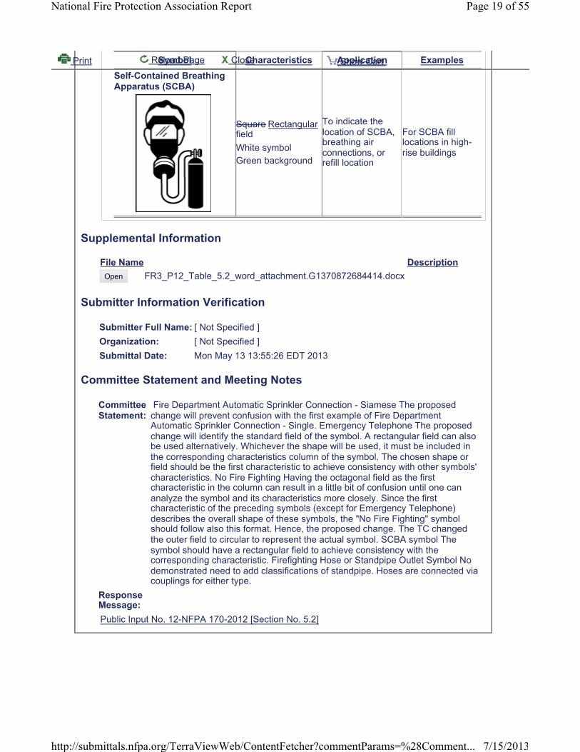
Symbol Comments
Public water main Indicate pipe size and material
Private water main Indicate pipe size and material
Water main underbuilding
Indicate pipe size andmaterial
Suction pipe Indicate pipe size and material
Thrust block
Riser
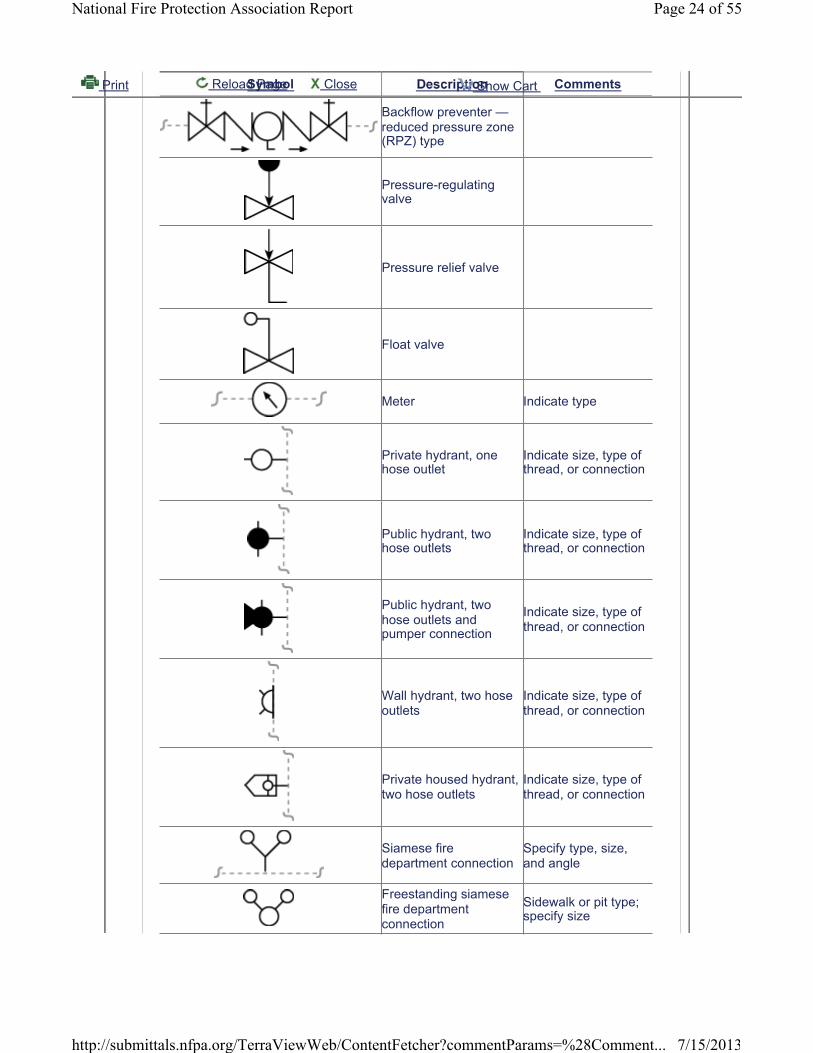
Pipe elbow up or downHeight on either side indicated by pipe height tags
Pipe tee up or downHeight of crossed pipes indicated by pipe height tags
Valves (general) Basic shape; indicate valve size
Valve in pit Indicate valve size
Post-indicator valve Indicate valve size
Key-operated valve Indicate valve size
OS&Y valve (outside screw and yoke, rising stem)
Indicate valve size
Indicating butterflyvalve Indicate valve size
Nonindicating valve(nonrising-stem valve) Indicate valve size
Check valveBasic shape; indicate valve size, direction of flow
Backflow preventer —double check type
Also referred to as a double check valve assembly
Print Reload Page Close Show Cart
Page 23 of 55National Fire Protection Association Report
7/15/2013http://submittals.nfpa.org/TerraViewWeb/ContentFetcher?commentParams=%28Comment...
Symbol Comments
Backflow preventer —reduced pressure zone (RPZ) type
Pressure-regulatingvalve
Pressure relief valve
Float valve
Meter Indicate type
Private hydrant, one hose outlet
Indicate size, type of thread, or connection
Public hydrant, two hose outlets
Indicate size, type of thread, or connection
Public hydrant, two hose outlets and pumper connection
Indicate size, type of thread, or connection
Wall hydrant, two hoseoutlets
Indicate size, type of thread, or connection
Private housed hydrant, two hose outlets
Indicate size, type of thread, or connection
Siamese fire department connection
Specify type, size, and angle
Freestanding siamese fire department connection
Sidewalk or pit type; specify size
Print Reload Page Close Show Cart
Page 24 of 55National Fire Protection Association Report
7/15/2013http://submittals.nfpa.org/TerraViewWeb/ContentFetcher?commentParams=%28Comment...

Symbol Comments
Single fire departmentconnection
Specify type, size, thread, and angle
Fire pump with driver Specify driver type and rated capacity
Freestanding testheader
Freestanding; specify number and sizes of outlets
Wall-mounted testheader
Wall; specify number and sizes of outlets
Screen/strainer
Supplemental Information
File Name DescriptionOpen Artwork_attachement_got_FR5_Table_7.2.pdf
Open 170FCfT07-2_7.jpg
Open 170FCfT07-2_8.jpg
Open FR5_PI19_Table_7.2.docx
Submitter Information Verification
Submitter Full Name: [ Not Specified ]Organization: [ Not Specified ]Submittal Date: Mon May 13 15:40:13 EDT 2013
Committee Statement and Meeting Notes
CommitteeStatement:
The technical Committee agrees with the submitter as there is no standard symbol to indicate fittings vertically within the page. This additional information provides a means of doing so. Without the pipe height tags there is no way to tell if an elbow goes up or down.
ResponseMessage:Committee Notes:
Date Submitted By
Jun 10, 2013
[ Not Specified ]
See word attachment & artwork attachment
Public Input No. 19-NFPA 170-2013 [Section No. 7.2]
Print Reload Page Close Show Cart
Page 25 of 55National Fire Protection Association Report
7/15/2013http://submittals.nfpa.org/TerraViewWeb/ContentFetcher?commentParams=%28Comment...

First Revision No. 16-NFPA 170-2013 [ Section No. 7.8 ]
Original Committee Hide Deleted
7.8 Symbols for Fire-Fighting Equipment.Symbols for fire-fighting equipment shall be as given in Table 7.8.Table 7.8 Symbols for Fire-Fighting Equipment
Symbol Description Comments
Fire-fighting equipment Basic shape
CO2 reel station
Dry chemical reel station
Fire hose valve connection Specify thread size
Foam reel station
Hose station, dry standpipe
Hose station, wet standpipe
Monitor nozzle, dry Specify orifice size
Monitor nozzle, charged Specify orifice size
Supplemental Information
File Name DescriptionOpen Artwork_attachment_for_FR_16_Table_7.8.pdf
Open Table_FR16_PI_18_Table_7.8_word_attachment.docx
Open 170FCfT07-8_9.jpg
Submitter Information Verification
Submitter Full Name: [ Not Specified ]Organization: [ Not Specified ]Submittal Date: Wed May 15 11:05:53 EDT 2013
Committee Statement and Meeting Notes
Print Reload Page Close Show Cart
Page 26 of 55National Fire Protection Association Report
7/15/2013http://submittals.nfpa.org/TerraViewWeb/ContentFetcher?commentParams=%28Comment...

CommitteeStatement:
This additional information broadens the use of these symbols to include hose connections.
Response Message:Committee Notes:
Date Submitted By
Jun 10, 2013
[ NotSpecified ]
See word attachement and artwork attachment
Print Reload Page Close Show Cart
Page 27 of 55National Fire Protection Association Report
7/15/2013http://submittals.nfpa.org/TerraViewWeb/ContentFetcher?commentParams=%28Comment...

Table 7.8 Symbols for Fire-Fighting Equipment
Symbol Description Comments ADD NEW SYMBOL Fire Hose Valve Connection Specify thread size


First Revision No. 30-NFPA 170-2013 [ Section No. 7.9 ]
Original Committee Hide Deleted
7.9* Miscellaneous Symbols.Miscellaneous symbols shall be as given in Table 7.9.Table 7.9 Miscellaneous Symbols
Print Reload Page Close Show Cart
Page 28 of 55National Fire Protection Association Report
7/15/2013http://submittals.nfpa.org/TerraViewWeb/ContentFetcher?commentParams=%28Comment...

Description Comments
Agent storage container Specify type of agent and mounting
Agent storage container —foam
Agent storage container —Halon
Agent storage container —carbon dioxide
Agent storage container —clean agent
Agent storage container —dry chemical
Agent storage container —water mist
Agent storage container —wet chemical
Special spray nozzle Specify type, orifice, size, other required data (shown here on pipe)
Fusible link Specify degrees
Fusible link with electrothermal feature Specify degrees
Solenoid valve
End of line device —resistor
End of line device — relay
End of line device —capacitor
End of line device —diode
Print Reload Page Close Show Cart
Page 29 of 55National Fire Protection Association Report
7/15/2013http://submittals.nfpa.org/TerraViewWeb/ContentFetcher?commentParams=%28Comment...

Description Comments
Transfer switch —automatic with handle
Transfer switch — manual with handle
Supplemental Information
File Name DescriptionOpen FR-30.docx
Submitter Information Verification
Submitter Full Name: Sandra StanekOrganization: National Fire Protection AssocSubmittal Date: Wed Jul 10 11:20:04 EDT 2013
Committee Statement and Meeting Notes
Committee Statement:
The TC has moved the following symbols to Table 8.3 ( see FR8 ): EOL re -End of line device-resistor; EOL ri - End of line device-relay; EOL c - End of Line device-capacitor; EOL D - End of Line device-diode; ATS -TransferSwitch-automatic with handle; MTS - Transfer switch manual with handle;SOV - Solenoid Valve
ResponseMessage:Committee Notes:
Date Submitted By
Jul 10, 2013
Sandra Stanek
Delete entries from Table 7.9 and move to Table 8.3; FR-8
Print Reload Page Close Show Cart
Page 30 of 55National Fire Protection Association Report
7/15/2013http://submittals.nfpa.org/TerraViewWeb/ContentFetcher?commentParams=%28Comment...

Move the following to Table 8.3 in FR-8:
Solenoid valve
End of line device — resistor
End of line device — relay
End of line device — capacitor
End of line device — diode
Transfer switch — automatic with handle
Transfer switch — manual with handle

First Revision No. 7-NFPA 170-2013 [ Section No. 8.2 ]
Original Committee Hide Deleted
8.2 Symbols for Control Panels.Global FR-17 Hide Deleted
Symbols for control panels shall be as given in Table 8.2 .Table 8.2 Symbols for Control Units (Panels)
Print Reload Page Close Show Cart
Page 31 of 55National Fire Protection Association Report
7/15/2013http://submittals.nfpa.org/TerraViewWeb/ContentFetcher?commentParams=%28Comment...

Basic shape
Amplifier rack
Area of refuge emergency communication system — master unit
Area of refuge emergency communication system — remote unit
Autonomous control unit
Battery cabinet
Cathode ray tube
Control panel for heating (H) , ventilation (V) , , air conditioning (AC), exhaust (E) , stairwell pressurization (P)
Dedicated function fire alarm control unit
Digital alarm communicator receiver
Digital alarm communicator transmitter
Elevator status/recall
Emergency communications control unit
Fire alarm annunciator
Fire alarm communicator
Fire alarm control panel
Fire alarm control unit (dedicated)
Fire alarm terminal cabinet
Fire alarm transponder n = transponder number
Fire suppression control panel xx denotes suppression typeFire suppression control unit xx denotes suppression type
Print Reload Page Close Show Cart
Page 32 of 55National Fire Protection Association Report
7/15/2013http://submittals.nfpa.org/TerraViewWeb/ContentFetcher?commentParams=%28Comment...

Graphic annunciator panel
LCD annunciator/display
Master fire alarm control unit
Notification circuit power booster, extender panel n = unit number
Power panel
Pre-action system/control unit
Printer
Protected premises control unit (local)
Purge panel
Relay panel
Releasing service fire alarm control unit
Remote voice evacuation microphone
Remotely located evacuation amplifier cabiner
Sprinkler alarm panel
Uninterruptible power supply
Voice evacuation control unit
Wireless control unit
Fire Suppression/Releasing Service Control Unit Types:
Carbon dioxide
Clean agent
Deluge fire sprinkler
Dry chemical
Fire fighter interface
Print Reload Page Close Show Cart
Page 33 of 55National Fire Protection Association Report
7/15/2013http://submittals.nfpa.org/TerraViewWeb/ContentFetcher?commentParams=%28Comment...

Fire pump controller
Foam
Halon
Water mist
Wet chemical
Supplemental Information
FileName Description
Open artwork_attachment_for_FR7_Table_8.2.pdf
Open FR7_PI_3_Table_8_2_word_attachment_edited_with_SLS_review1.docx
Open 170FCfT08-2_3.jpg
Open 170FCfT08-2_4.jpg
Open 170FCfT08-2_29.jpg
Open 170FCfT08-2_47.jpg
Open 170FCfT08-2_48.jpg
Submitter Information Verification
Submitter Full Name: [ Not Specified ]Organization: [ Not Specified ]Submittal Date: Mon May 13 16:36:03 EDT 2013
Committee Statement and Meeting Notes
CommitteeStatement:
The TC recognizes the need for adding the following new symbols: #1 add subscript to FACU as dedicated #2 add italisized "n" to Fire Alarm transponder #3 revise HVA symbol to HVAC for industry standard #4 add subscript to FACU for "dedicated" #5 connection that indicates fire pump status. The disconnect is integral to the fire pump controller. See attachment for new symbols
Response Message:
Print Reload Page Close Show Cart
Page 34 of 55National Fire Protection Association Report
7/15/2013http://submittals.nfpa.org/TerraViewWeb/ContentFetcher?commentParams=%28Comment...

Date Submitted By
Jun 10, 2013
[ NotSpecified ]
See word attachemnt and artwork attachment
Public Input No. 3-NFPA 170-2012 [Section No. 8.2]
Print Reload Page Close Show Cart
Page 35 of 55National Fire Protection Association Report
7/15/2013http://submittals.nfpa.org/TerraViewWeb/ContentFetcher?commentParams=%28Comment...

Table 8.2 Symbols for Control Units (Panels)
Symbol Description
Basic shape
Fire alarm control panel
D Fire alarm control unit (dedicated)
SEE ARTWORK
Fire alarm transponder n = transponder number
Fire alarm annunciator
LCD annunciator/display
Notification circuit power booster, extender panel n = unit number
Fire alarm terminal cabinet
Battery cabinet
Voice evacuation control unit
Remote voice evacuation microphone
Graphic annunciator panel
Uninterruptible power supply
Power panel
Cathode ray tube
Printer
Emergency communications control unit
Fire suppression control panel xx denotes suppression type
Fire suppression control unit xx denotes suppression type
Amplifier rack
Area of refuge emergency communication system — master unit
Area of refuge emergency communication system — remote unit
Autonomous control unit
Remotely located evacuation amplifier cabiner
Elevator status/recall
Digital alarm communicator receiver

Digital alarm communicator transmitter
Fire alarm communicator
HVAC Control panel for heating (H), ventilation (V), exhaust, stairwell pressurization, air conditioning (AC)
Purge panel
Pre-action system
Relay panel
Sprinkler alarm panel
Wireless control unit
Master fire alarm control unit
Protected premises control unit (local)
Dedicated function fire alarm control unit
Releasing service fire alarm control unit
Fire Suppression/Releasing Service Control Unit Types:
Carbon dioxide
Dry chemical
Halon
Foam
Wet chemical
Clean agent
Water mist
Deluge fire sprinkler
SEE ARTWORK Fire pump controller SEE ARTWORK Fire fighter interface
Formatted: Font: Bold

First Revision No. 8-NFPA 170-2013 [ Section No. 8.3 ]
Original Committee Hide Deleted
8.3* Symbols for Fire Alarms, Detection, and Related Equipment — Signal Initiating Devices and Activation Switches.
Global FR-17 Hide Deleted
Symbols for signal initiating devices and activation switches shall be as given in Table 8.3 . Table 8.3 Symbols for Signal Initiating Devices and Activation Switches
Print Reload Page Close Show Cart
Page 36 of 55National Fire Protection Association Report
7/15/2013http://submittals.nfpa.org/TerraViewWeb/ContentFetcher?commentParams=%28Comment...

Abort Switch Types:
Abort switch — basic shape
Abort switch
Abort switch — Carbon dioxide
Abort switch — Clean agent
Abort switch — Deluge fire sprinkler
Abort switch — Dry chemical
Abort switch — Foam
Abort switch — Halon
Manual releasing station
Abort switch — Preaction
Abort switch — Water mist
Abort switch — Wet chemical
Addressable Modules:
Addressable input monitor module
Addressable input/output module; # denotes number of inputs and outputs
Addressable output control module
Print Reload Page Close Show Cart
Page 37 of 55National Fire Protection Association Report
7/15/2013http://submittals.nfpa.org/TerraViewWeb/ContentFetcher?commentParams=%28Comment...

Automatic Detection Type:
Automatic detection and supervisory devices — basic shape
Flame Detector/Sensor Detection Types:
Flame detector basic shapeXX = detection type
Combination ultraviolet/infrared
Infrared detector
Ultraviolet detector
Visible radiation detector
Gas Detector/Sensor Subscript Examples Detection Types:
Gas detector/sensor basic shapeXX = gas type
Carbon dioxide detector
Carbon monoxide detector
Hydrogen chloride detector
Methane detector
Heat Detector/Sensor Detection Types:
Heat detector/sensor — XX = type basic shape
Print Reload Page Close Show Cart
Page 38 of 55National Fire Protection Association Report
7/15/2013http://submittals.nfpa.org/TerraViewWeb/ContentFetcher?commentParams=%28Comment...

Combination rate of rise/fixed temperature
Fixed temperature
Heat detector — line type
Heat detector/sensor (thermal detection) orientation not to be changed
Rate compensation
Rate of rise only
Interface and Supervisory Devices:
End of line device — capacitor
End of line device — diode
End of line device — relay
End of line device — resistor
Flow detector/switch
High temperature switch
Level detector/switch
Low temperature switch
Non-addressable output relay
Pressure detector/switch
Solenoid valve
Temperature supervisory switch
Print Reload Page Close Show Cart
Page 39 of 55National Fire Protection Association Report
7/15/2013http://submittals.nfpa.org/TerraViewWeb/ContentFetcher?commentParams=%28Comment...

Transfer switch — automatic with handle
Transfer switch — manual with handle
Valve supervisory switch
Valve with valve integral supervisory switch
Water detector
Manual Station Fire Alarm Box Types:
Manual station — basic shape
Manual station — carbon Carbon dioxide
Manual station — clean Clean agent
Manual station — deluge Deluge fire sprinkler
Drill key
Manual station — dry Dry chemical
Fire alarm master box
Manual station — foam Foam
Manual station — Halon
Manual station — preaction Preaction
Manual station — pull Pull station/fire alarm box
Manual station — water Water mist
Manual station — wet Wet chemical
Smoke Detector Detection /Sensor Types:
Smoke detector/sensor — basic shape orientation not to bechanged
Print Reload Page Close Show Cart
Page 40 of 55National Fire Protection Association Report
7/15/2013http://submittals.nfpa.org/TerraViewWeb/ContentFetcher?commentParams=%28Comment...

Air sampling
In duct
Ionization
Photoelectric
Relay base
Single station
Smoke/heat detector/carbon monoxide detector
Smoke/heat detector/sensor combination
Smoke detector/sensor— beam receiver
Smoke detector/sensor — beam transmitter
Smoke detector/sensor — XX = type
Smoke detector/sensor for duct
Sounder base
Supplemental Information
Print Reload Page Close Show Cart
Page 41 of 55National Fire Protection Association Report
7/15/2013http://submittals.nfpa.org/TerraViewWeb/ContentFetcher?commentParams=%28Comment...

File Name DescriptionOpen artwork_attachment_for_FR8_Table_8.3.pdf
Open FR8_table_8_3_word_attachment_edited_with_SLS_review1.docx
Open 170FCfT08-3_10.jpg
Open 170FCfT08-3_14.jpg
Open 170FCfT08-3_15.jpg
Submitter Information Verification
Submitter Full Name: [ Not Specified ]Organization: [ Not Specified ]Submittal Date: Mon May 13 17:08:32 EDT 2013
Committee Statement and Meeting Notes
CommitteeStatement:
1. Combined combination heat detector/smoke detector into one symbol. The TC is changing the shape of symbol only. By combining this into one symbol, it allows for easier delineation between the two meanings. 2. The TC is not adding the smoke detector sensor for the duct as it adds confusion and could cause designer errors. 3. This symbol already exists in Table 8.5 therefore the TC is not adding it. 4. Adding new symbol to "Gas Detector/Sensor Subscript Examples" (changing name to Gas Detection Types) for designation of smoke/heat detector/carbon monoxide detector does exist, and a symbol is required. 5. Moving symbols within Table for ease of use
Response Message:Committee Notes:
Date Submitted By
Jun 10, 2013
[ NotSpecified ]
see word attachment and artwork attachment
Public Input No. 4-NFPA 170-2012 [Section No. 8.3]
Print Reload Page Close Show Cart
Page 42 of 55National Fire Protection Association Report
7/15/2013http://submittals.nfpa.org/TerraViewWeb/ContentFetcher?commentParams=%28Comment...

Table 8.3 Symbols for Signal Initiating Devices and Activation Switches
Symbol Description
Manual station — basic shape
Manual station — Pull station/fire alarm box
Fire alarm master box
Drill key
Abort switch — basic shape
Abort switch
Manual releasing station
Automatic detection and supervisory devices — basic shape
Heat detector/sensor (thermal detection) orientation not to be changed
Heat detector/sensor — XX = type basic shape
Heat detector — line type
Smoke detector/sensor — basic shape orientation not to be changed
Smoke detector/sensor — XX = type
Smoke/heat detector/sensor combination
SEE ATTACHED Smoke/heat detector/carbon monoxide detector
Smoke detector/sensor — beam transmitter
Smoke detector/sensor— beam receiver
Smoke detector/sensor for duct
Gas detector/sensor basic shape XX = gas type
Flame detector basic shape XX = detection type

Water detector
Manual Fire Alarm Box Types:
Manual station — Carbon dioxide
Manual station — Dry chemical
Manual station — Halon
Manual station — Foam
Manual station — Wet chemical
Manual station — Clean agent
Manual station — Water mist
Manual station — Deluge fire sprinkler
Manual station — Preaction
Abort Switch Types:
Abort switch — carbon dioxide
Abort switch — dry chemical
Abort switch — Halon
Abort switch — foam
Abort switch — wet chemical
Abort switch — clean agent
Abort switch — water mist
Abort switch — deluge fire sprinkler
Abort switch — preaction
Heat Detection/Sensor Types:
Combination rate of rise/fixed temperature
Formatted: Font: Bold
Formatted: Font: Bold
Formatted: Font: Bold
Formatted: Font: Bold
Formatted: Font: Bold

Rate compensation
Fixed temperature
Rate of rise only
Smoke Detection/Sensor Types:
Air sampling
Photoelectric
Ionization
Relay base
Single station
Sounder base
In duct
Gas Detection Types:
Carbon monoxide detector
Carbon dioxide detector
Hydrogen chloride detector
Methane detector
Flame Detection Types:
Ultraviolet
Infrared
Combination ultraviolet/infrared
Formatted: Font: Bold
Formatted: Font: Bold
Formatted: Font: Bold
Formatted: Font: Bold
Formatted: Font: Bold
Formatted: Font: Bold

Visible radiation
Flow detector/switch
Pressure detector/switch
Valve supervisory switch
Valve with valve integral supervisory switch
Level detector/switch
Temperature supervisory switch
High temperature switch
Low temperature switch
Addressable input monitor module
Addressable output control module
Addressable input/output module; # denotes number of inputs and outputs
Non-addressable output relay


First Revision No. 24-NFPA 170-2013 [ Section No. 8.5 ]
Original Committee Hide Deleted
8.5 Related Equipment.Global FR-17 Hide Deleted
Symbols for related equipment shall be as given in Table 8.5 . Table 8.5 Symbols for Related Equipment
Print Reload Page Close Show Cart
Page 43 of 55National Fire Protection Association Report
7/15/2013http://submittals.nfpa.org/TerraViewWeb/ContentFetcher?commentParams=%28Comment...

Air sampling detector piping
Door closer
Door holder
End of line resistor
Fire service or emergency phone station — accessible
Fire service or emergency phone station — basic shape
Fire service or emergency phone station — handset
Fire service or emergency phone station — jack
Floor Warden Station
Integrated smoke sensor and door closer
Isolator module (Style 6 or 7 fault protection)
Junction box
Mass notification system
Sync adapter module (strobe synchronization)
Print Reload Page Close Show Cart
Page 44 of 55National Fire Protection Association Report
7/15/2013http://submittals.nfpa.org/TerraViewWeb/ContentFetcher?commentParams=%28Comment...

Watchman's tour station
Supplemental Information
File Name DescriptionOpen Changes_to_Table_8.5.pdf
Open 170FCfT08-5_6.jpg
Open 170FCfT08-5_7.jpg
Open 170FCfT08-5_8.jpg
Open 170FCfT08-5_9.jpg
Open 170FCfT08-5_12.jpg
Open 170FCfT08-5_13.jpg
Submitter Information Verification
Submitter Full Name: [ Not Specified ]Organization: [ Not Specified ]Submittal Date: Fri May 24 14:32:40 EDT 2013
Committee Statement and Meeting Notes
CommitteeStatement:
The TC changed the location of the subscript for the phone stations, added "Floor Warden Station" and "Mass Notification System", and edited the "junction box" symbol. See attachment for more information.
ResponseMessage:Committee Notes:
Date Submitted By
May 29, 2013
[ Not Specified ]
See attachment for more information
Print Reload Page Close Show Cart
Page 45 of 55National Fire Protection Association Report
7/15/2013http://submittals.nfpa.org/TerraViewWeb/ContentFetcher?commentParams=%28Comment...


First Revision No. 27-NFPA 170-2013 [ Section No. 8.6 ]
Original Committee Hide Deleted
8.6 Symbols for Smoke/Pressurization Control.Global FR-17 Hide Deleted
Symbols for smoke/pressurization controls shall be as given in Table 8.6 . Table 8.6 Symbols for Smoke/Pressurization Controls
Print Reload Page Close Show Cart
Page 46 of 55National Fire Protection Association Report
7/15/2013http://submittals.nfpa.org/TerraViewWeb/ContentFetcher?commentParams=%28Comment...

Description Comments
Dampers — barometric
Dampers — fire
Dampers — fire/smoke
Dampers — motorizedfire/smoke
Dampers — smoke
Fans — duct Arrow indicates direction of flow
Fans — general Arrow indicates direction of flow
Print Reload Page Close Show Cart
Page 47 of 55National Fire Protection Association Report
7/15/2013http://submittals.nfpa.org/TerraViewWeb/ContentFetcher?commentParams=%28Comment...

Description Comments
Fans — roof Arrow indicates direction of flow
Fans — wall Arrow indicates direction of flow
Hand (manual)/ off-automatic
Pressurized stairwell Orient as required for base or headinjection
Purge controls — manualcontrol
Ventilation openings Orient as required for intake orexhaust
Supplemental Information
File Name DescriptionOpen Changes_to_Table_8.6.pdf
Open 170FCfT08-6_8.jpg
Open 170FCfT08-6_9.jpg
Open 170FCfT08-6_10.jpg
Submitter Information Verification
Submitter Full Name: [ Not Specified ]Organization: [ Not Specified ]Submittal Date: Wed May 29 11:32:17 EDT 2013
Committee Statement and Meeting Notes
CommitteeStatement:
The TC has removed the circle with the wisp and changed the symbol to a polygon for Dampers - smoke, Dampers - fire/smoke, Damopers - motorized fire/smoke. See attachment for symbol changes
ResponseMessage:Committee Notes:
Date Submitted By
May 29, 2013
[ Not Specified ]
There are no text changes to this table, only symbol changes. See attachment
Print Reload Page Close Show Cart
Page 48 of 55National Fire Protection Association Report
7/15/2013http://submittals.nfpa.org/TerraViewWeb/ContentFetcher?commentParams=%28Comment...


First Revision No. 14-NFPA 170-2013 [ Section No. 11.1 ]
Original Committee Hide Deleted
11.1 Introduction.This chapter shall provide requirements on the preparation of floor diagrams and plans, posted within a building, to show the egress evacuation paths and locations of equipment used during an emergency. Building emergency information shall be provided to instruct or guide occupants in how to report an emergency; when to evacuate to the outside evacuation assembly area, to a designated area of refuge, to an area of rescue assistance, or to a designated shelter area; when to remain in place; or when to employ any combination of these options.
Submitter Information Verification
Submitter Full Name: [ Not Specified ]Organization: [ Not Specified ]Submittal Date: Tue May 14 08:39:46 EDT 2013
Committee Statement and Meeting Notes
CommitteeStatement:
The Technical Committee is adding the word "evacuation" following consistency with Sec. 11.4.1.1
Response Message:
Print Reload Page Close Show Cart
Page 49 of 55National Fire Protection Association Report
7/15/2013http://submittals.nfpa.org/TerraViewWeb/ContentFetcher?commentParams=%28Comment...

First Revision No. 18-NFPA 170-2013 [ Section No. 11.2.2 ]
Original Committee Hide Deleted
11.2.2*A basic floor plan shall show a minimum of two ways to exit from the location of where the diagram/plan is posted, when possible, show the entire floor plan, but when unable to provide a key plan highlighting the area shown in accordance with NFPA 101, Life Safety Code. A plan shall show a minimum of two ways to exit from the location of where the diagram/plan is posted, showing the entire floor plan in accordance with NFPA 101 , Life Safety Code . When unable to show the entire floor plan, provide a key plan highlighting the area.
Submitter Information Verification
Submitter Full Name: [ Not Specified ]Organization: [ Not Specified ]Submittal Date: Thu May 16 07:29:13 EDT 2013
Committee Statement and Meeting Notes
CommitteeStatement:
The technical Committee recognizes the shape of the entire plan is much easier to recognize than small sections. But, if necessary, the key plan gives the viewer a full understanding of the building.
ResponseMessage:
Print Reload Page Close Show Cart
Page 50 of 55National Fire Protection Association Report
7/15/2013http://submittals.nfpa.org/TerraViewWeb/ContentFetcher?commentParams=%28Comment...

First Revision No. 19-NFPA 170-2013 [ Section No. 11.3.2 ]
Original Committee Hide Deleted
11.3.2There shall be a notation showing the location of the viewer and their orientation withthe "you are here" notation pointing up to the sign location . This shall be the most dominant graphic on the diagram.
Submitter Information Verification
Submitter Full Name: [ Not Specified ]Organization: [ Not Specified ]Submittal Date: Thu May 16 09:21:55 EDT 2013
Committee Statement and Meeting Notes
CommitteeStatement:
The technical committee clarifies the confusion in sometimes the "you are here" notation giving the impression that the sign is on the other side of the wall.
Response Message:
Print Reload Page Close Show Cart
Page 51 of 55National Fire Protection Association Report
7/15/2013http://submittals.nfpa.org/TerraViewWeb/ContentFetcher?commentParams=%28Comment...

First Revision No. 20-NFPA 170-2013 [ Section No. 11.4.3 ]
Original Committee Hide Deleted
11.4.3The diagram or plan shall provide emergency evacuation guidelines describing the different emergency alert signals and of when and what to do when the signals are sounded. If there are not any signals, the guidelines shall describe how the occupants will be instructed what to do in case of an emergency.
Submitter Information Verification
Submitter Full Name: [ Not Specified ]Organization: [ Not Specified ]Submittal Date: Thu May 16 09:27:05 EDT 2013
Committee Statement and Meeting Notes
CommitteeStatement:
The Technical Committee recognizes there are several types of emergency conditions that require different emergency alerts and instructions.
ResponseMessage:
Print Reload Page Close Show Cart
Page 52 of 55National Fire Protection Association Report
7/15/2013http://submittals.nfpa.org/TerraViewWeb/ContentFetcher?commentParams=%28Comment...

First Revision No. 29-NFPA 170-2013 [ New Section after B.5.3.2 ]
Committee Hide Deleted
Annex C Emergency Responder MapThis annex is not a part of the requirements of this NFPA document but is intendedfor informational purposes only.C.1 Emergency Responder Plan.The plan shown in Figure C.1(a) and Figure C.1(b) provides emergency responders an example of maps showing the interior and exterior locations of the building using the symbols from Table 5.2 and information from Chapter 9 . See Figure C.1(a)and Figure C.1(b) .Figure C.1(a) Emergency Response Map First Floor, Interior.
Figure C.1(b) Emergency Response Map Exterior.
Print Reload Page Close Show Cart
Page 53 of 55National Fire Protection Association Report
7/15/2013http://submittals.nfpa.org/TerraViewWeb/ContentFetcher?commentParams=%28Comment...
Supplemental Information
FileName Description
Open Artwork_attachment_for_Emer_Response_Map_interior_Annex_C.1a.pdf
Open Artwork_for_Emer_Response_Map_exterior_Annex_C.1b.pdf
Open 170FCfC-01_a_.jpg
Open 170FCfC-01_b_.jpg
Submitter Information Verification
Submitter Full Name: Sandra StanekOrganization: National Fire Protection AssocSubmittal Date: Tue Jul 02 08:47:45 EDT 2013
Committee Statement and Meeting Notes
Committee Statement:
The technical committee has provided emergency responders an informational plan showing property and building access, fire hose connections, utility shut off locations, fire alarm panel locations, fire protection features, evacuation assembly areas and other information. This plan shows an example of utilization of NFPA 170 symbols for emergency response.
Response Message:Committee Notes:
Date Submitted By
Jul 2, 2013
SandraStanek
Editorial: move existing Annex C Informational References to new Annex D
Print Reload Page Close Show Cart
Page 54 of 55National Fire Protection Association Report
7/15/2013http://submittals.nfpa.org/TerraViewWeb/ContentFetcher?commentParams=%28Comment...


![First Revision No. 17-NFPA 170-2013 [ Global Input ]First Revision No. 17-NFPA 170-2013 [ Global Input ] Alphabetize tables within Chapter 8 NFPA 170 as follows: Table 8.2 Symbols](https://img.pdfslide.us/doc/110x75/5e749e445391014044180e21/first-revision-no-17-nfpa-170-2013-global-input-first-revision-no-17-nfpa.jpg)


![Public Input No. 13-NFPA 170-2012 [ Global Input ] Statement of](https://img.pdfslide.us/doc/110x75/58a022121a28ab78628b5534/public-input-no-13-nfpa-170-2012-global-input-statement-of-.jpg)