Embed Size (px)
Citation preview

(English) DM-SG0005-01
Dealer's Manual
ROAD MTB Trekking
City Touring/Comfort Bike
URBAN SPORT E-BIKE
Nexus
SG-3R40SG-3R45SG-3R75SG-3R75-ASG-3R75-BSG-3D55SG-3C41
SL-3S35-ESL-3S41-ESL-3S42-E
SM-BC03SM-BC04SM-BC06
CJ-NX40
2
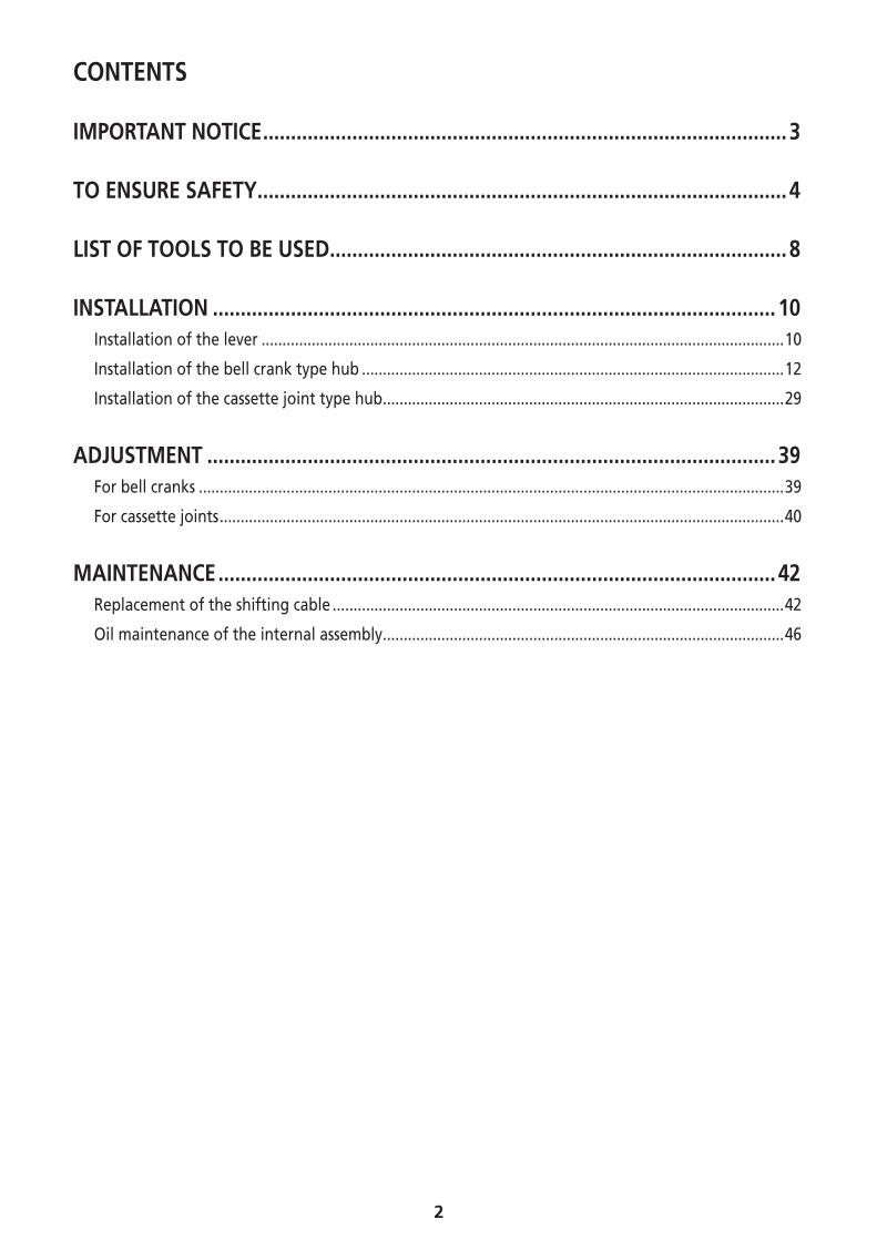
CONTENTS
IMPORTANT NOTICE .............................................................................................. 3
TO ENSURE SAFETY ............................................................................................... 4
LIST OF TOOLS TO BE USED .................................................................................. 8
INSTALLATION ..................................................................................................... 10Installation of the lever .............................................................................................................................10
Installation of the bell crank type hub .....................................................................................................12
Installation of the cassette joint type hub ................................................................................................29
ADJUSTMENT ...................................................................................................... 39For bell cranks ............................................................................................................................................39
For cassette joints .......................................................................................................................................40
MAINTENANCE .................................................................................................... 42Replacement of the shifting cable ............................................................................................................42
Oil maintenance of the internal assembly ................................................................................................46
3
IMPORTANT NOTICE
IMPORTANT NOTICE
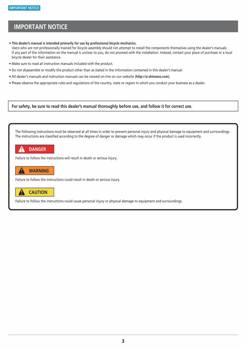
• This dealer’s manual is intended primarily for use by professional bicycle mechanics. Users who are not professionally trained for bicycle assembly should not attempt to install the components themselves using the dealer’s manuals. If any part of the information on the manual is unclear to you, do not proceed with the installation. Instead, contact your place of purchase or a local bicycle dealer for their assistance.
• Make sure to read all instruction manuals included with the product.
• Do not disassemble or modify the product other than as stated in the information contained in this dealer’s manual.
• All dealer's manuals and instruction manuals can be viewed on-line on our website (http://si.shimano.com).
• Please observe the appropriate rules and regulations of the country, state or region in which you conduct your business as a dealer.
For safety, be sure to read this dealer’s manual thoroughly before use, and follow it for correct use.
The following instructions must be observed at all times in order to prevent personal injury and physical damage to equipment and surroundings.The instructions are classified according to the degree of danger or damage which may occur if the product is used incorrectly.
DANGER
Failure to follow the instructions will result in death or serious injury.
WARNING
Failure to follow the instructions could result in death or serious injury.
CAUTION
Failure to follow the instructions could cause personal injury or physical damage to equipment and surroundings.
4
TO ENSURE SAFETY
TO ENSURE SAFETY
WARNING
• When installing components, be sure to follow the instructions that are given in the instruction manuals.It is recommended that you use only genuine Shimano parts. If parts such as bolts and nuts become loose or damaged, the bicycle may suddenly fall over, which may cause serious injury.In addition, if adjustments are not carried out correctly, problems may occur, and the bicycle may suddenly fall over, which may cause serious injury.
• Be sure to wear safety glasses or goggles to protect your eyes while performing maintenance tasks such as replacing parts.
• After reading the dealer's manual thoroughly, keep it in a safe place for later reference.
Be sure to also inform users of the following: • Each bicycle may handle slightly differently depending on the model.Therefore, be sure to learn the proper braking technique (including brake lever pressure and bicycle control characteristics) and operation of your bicycle. Improper use of your bicycle's brake system may result in loss of control, the bicycle falling over, and severe injury. For proper operation, consult your professional bicycle dealer or the bicycle's instruction manual. It is also important to practice riding as well as braking operation, etc.
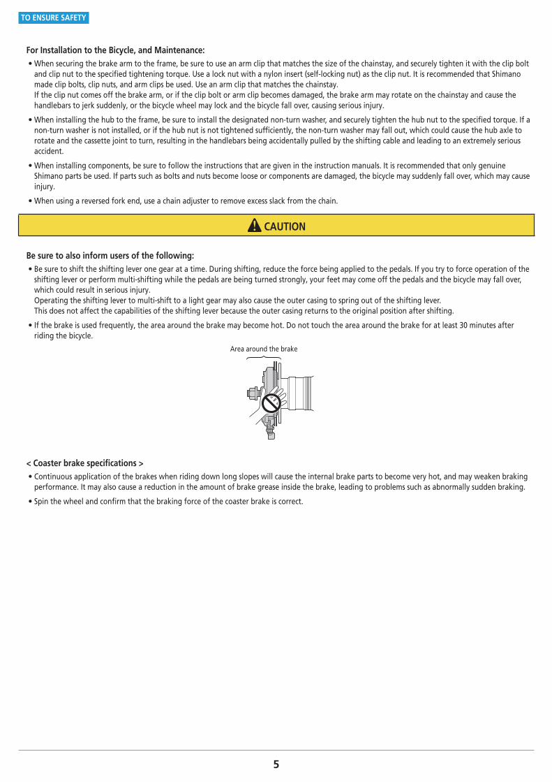
• The brake levers are equipped with a mode switching mechanism to make them compatible with cantilever brakes and roller brakes or V-BRAKE brakes with power modulator.If the incorrect mode is selected it may cause either excessive or insuffi cient braking force to occur, which could result in dangerous accidents.Be sure to select the mode in accordance with the instructions given in the table below.
Mode position Applicable brake
C : Mode position for compatibility with cantilever
brakes
R : Mode position for compatibility with roller
brakes
C R
V
V
C R
V
V
C R
C/R position
• Cantilever brakes
• Roller brakes
V : Mode position for compatibility with V-BRAKE
brakes with power modulator C R
V
V
C R
V
V position
• V-BRAKE brakes with power modulator
Use the brake levers with mode switching mechanism in the combinations given above.
• When installing components, be sure to follow the instructions that are given in the instruction manuals. It is recommended that you use only genuine Shimano parts. If parts such as bolts and nuts become loose or components are damaged, the bicycle may suddenly fall over, which may cause injury.
• Check that the wheels are fastened securely before riding the bicycle. If the wheels are loose in any way, they may come off the bicycle and serious injury may result.
5
TO ENSURE SAFETY
For Installation to the Bicycle, and Maintenance: • When securing the brake arm to the frame, be sure to use an arm clip that matches the size of the chainstay, and securely tighten it with the clip bolt and clip nut to the specified tightening torque. Use a lock nut with a nylon insert (self-locking nut) as the clip nut. It is recommended that Shimano made clip bolts, clip nuts, and arm clips be used. Use an arm clip that matches the chainstay. If the clip nut comes off the brake arm, or if the clip bolt or arm clip becomes damaged, the brake arm may rotate on the chainstay and cause the handlebars to jerk suddenly, or the bicycle wheel may lock and the bicycle fall over, causing serious injury.
• When installing the hub to the frame, be sure to install the designated non-turn washer, and securely tighten the hub nut to the specified torque. If a non-turn washer is not installed, or if the hub nut is not tightened sufficiently, the non-turn washer may fall out, which could cause the hub axle to rotate and the cassette joint to turn, resulting in the handlebars being accidentally pulled by the shifting cable and leading to an extremely serious accident.
• When installing components, be sure to follow the instructions that are given in the instruction manuals. It is recommended that only genuine Shimano parts be used. If parts such as bolts and nuts become loose or components are damaged, the bicycle may suddenly fall over, which may cause injury.
• When using a reversed fork end, use a chain adjuster to remove excess slack from the chain.
CAUTION
Be sure to also inform users of the following: • Be sure to shift the shifting lever one gear at a time. During shifting, reduce the force being applied to the pedals. If you try to force operation of the shifting lever or perform multi-shifting while the pedals are being turned strongly, your feet may come off the pedals and the bicycle may fall over, which could result in serious injury. Operating the shifting lever to multi-shift to a light gear may also cause the outer casing to spring out of the shifting lever. This does not affect the capabilities of the shifting lever because the outer casing returns to the original position after shifting.
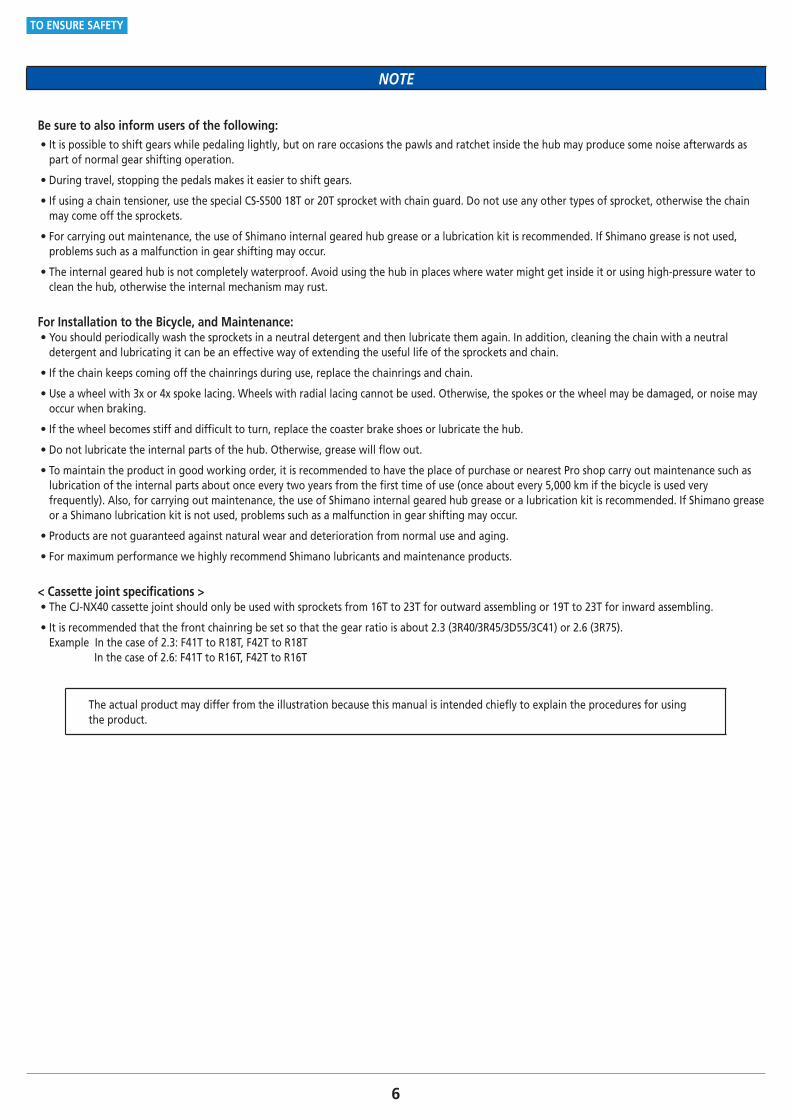
• If the brake is used frequently, the area around the brake may become hot. Do not touch the area around the brake for at least 30 minutes after riding the bicycle.
Area around the brake
< Coaster brake specifications > • Continuous application of the brakes when riding down long slopes will cause the internal brake parts to become very hot, and may weaken braking performance. It may also cause a reduction in the amount of brake grease inside the brake, leading to problems such as abnormally sudden braking.
• Spin the wheel and confirm that the braking force of the coaster brake is correct.
6
TO ENSURE SAFETY
NOTE
Be sure to also inform users of the following: • It is possible to shift gears while pedaling lightly, but on rare occasions the pawls and ratchet inside the hub may produce some noise afterwards as part of normal gear shifting operation.
• During travel, stopping the pedals makes it easier to shift gears.
• If using a chain tensioner, use the special CS-S500 18T or 20T sprocket with chain guard. Do not use any other types of sprocket, otherwise the chain may come off the sprockets.
• For carrying out maintenance, the use of Shimano internal geared hub grease or a lubrication kit is recommended. If Shimano grease is not used, problems such as a malfunction in gear shifting may occur.
• The internal geared hub is not completely waterproof. Avoid using the hub in places where water might get inside it or using high-pressure water to clean the hub, otherwise the internal mechanism may rust.
For Installation to the Bicycle, and Maintenance: • You should periodically wash the sprockets in a neutral detergent and then lubricate them again. In addition, cleaning the chain with a neutral detergent and lubricating it can be an effective way of extending the useful life of the sprockets and chain.
• If the chain keeps coming off the chainrings during use, replace the chainrings and chain.
• Use a wheel with 3x or 4x spoke lacing. Wheels with radial lacing cannot be used. Otherwise, the spokes or the wheel may be damaged, or noise may occur when braking.
• If the wheel becomes stiff and difficult to turn, replace the coaster brake shoes or lubricate the hub.
• Do not lubricate the internal parts of the hub. Otherwise, grease will flow out.
• To maintain the product in good working order, it is recommended to have the place of purchase or nearest Pro shop carry out maintenance such as lubrication of the internal parts about once every two years from the first time of use (once about every 5,000 km if the bicycle is used very frequently). Also, for carrying out maintenance, the use of Shimano internal geared hub grease or a lubrication kit is recommended. If Shimano grease or a Shimano lubrication kit is not used, problems such as a malfunction in gear shifting may occur.
• Products are not guaranteed against natural wear and deterioration from normal use and aging.
• For maximum performance we highly recommend Shimano lubricants and maintenance products.
< Cassette joint specifications > • The CJ-NX40 cassette joint should only be used with sprockets from 16T to 23T for outward assembling or 19T to 23T for inward assembling.
• It is recommended that the front chainring be set so that the gear ratio is about 2.3 (3R40/3R45/3D55/3C41) or 2.6 (3R75).Example In the case of 2.3: F41T to R18T, F42T to R18T
In the case of 2.6: F41T to R16T, F42T to R16T
The actual product may differ from the illustration because this manual is intended chiefly to explain the procedures for using the product.
LIST OF TOOLS TO BE USED
8
LIST OF TOOLS TO BE USED
LIST OF TOOLS TO BE USED
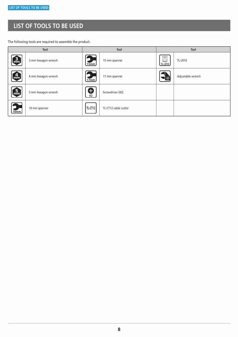
The following tools are required to assemble the product.
Tool Tool Tool
3 mm hexagon wrench 15 mm spanner TL-LR10
4 mm hexagon wrench 17 mm spanner Adjustable wrench
5 mm hexagon wrench Screwdriver [#2]
10 mm spanner TL-CT12 cable cutter

INSTALLATION
10To be continued on next page
INSTALLATION
Installation of the lever
INSTALLATION
� Installation of the lever
Installation of the REVOSHIFT lever
1
(B)(A)
(C)
(z)
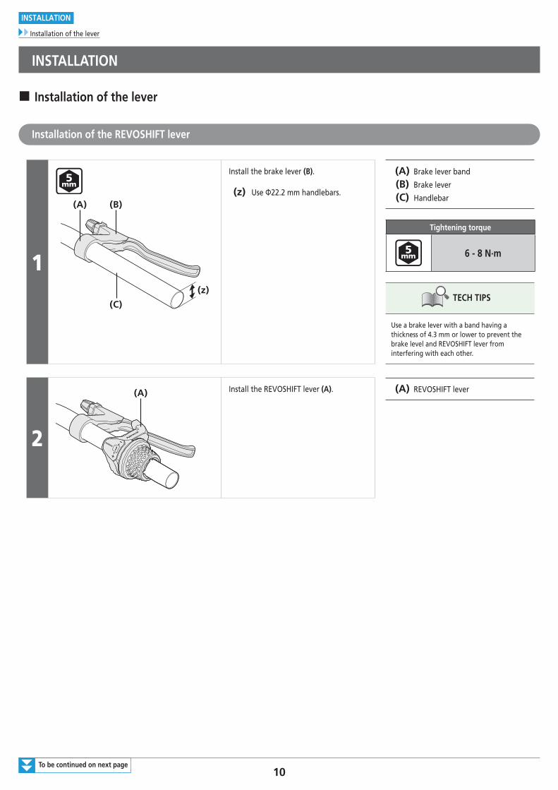
Install the brake lever (B).
(z) Use Φ22.2 mm handlebars.
(A) Brake lever band
(B) Brake lever
(C) Handlebar
Tightening torque
6 - 8 N·m
TECH TIPS
Use a brake lever with a band having a thickness of 4.3 mm or lower to prevent the brake level and REVOSHIFT lever from interfering with each other.
2
(A) Install the REVOSHIFT lever (A). (A) REVOSHIFT lever
11
INSTALLATION
Installation of the lever
3 (A)
(B)
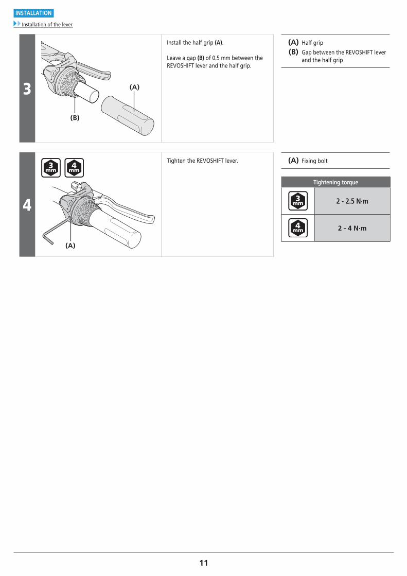
Install the half grip (A).
Leave a gap (B) of 0.5 mm between the REVOSHIFT lever and the half grip.
(A) Half grip
(B) Gap between the REVOSHIFT lever and the half grip
4
(A)
Tighten the REVOSHIFT lever. (A) Fixing bolt
Tightening torque
2 - 2.5 N·m
2 - 4 N·m
12To be continued on next page
INSTALLATION
Installation of the bell crank type hub
� Installation of the bell crank type hub
Installation of the shifting cable
1
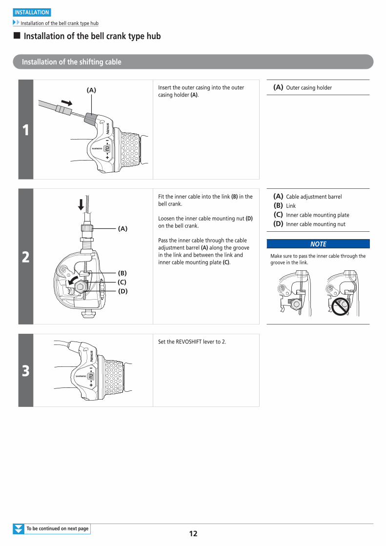
(A) Insert the outer casing into the outer casing holder (A).
(A) Outer casing holder
2
(A)
(B)(C)(D)
Fit the inner cable into the link (B) in the bell crank.
Loosen the inner cable mounting nut (D) on the bell crank.
Pass the inner cable through the cable adjustment barrel (A) along the groove in the link and between the link and inner cable mounting plate (C).
(A) Cable adjustment barrel
(B) Link
(C) Inner cable mounting plate
(D) Inner cable mounting nut
NOTE
Make sure to pass the inner cable through the groove in the link.
3
Set the REVOSHIFT lever to 2.
13
INSTALLATION
Installation of the bell crank type hub
4
(y) (y)
(z)
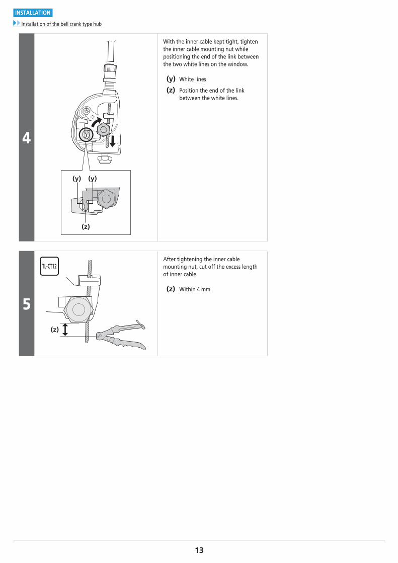
With the inner cable kept tight, tighten the inner cable mounting nut while positioning the end of the link between the two white lines on the window.
(y) White lines
(z) Position the end of the link between the white lines.
5(z)
After tightening the inner cable mounting nut, cut off the excess length of inner cable.
(z) Within 4 mm
14To be continued on next page
INSTALLATION
Installation of the bell crank type hub
Installation of the sprocket to the hub (SM-GEAR)
(z)
(A)
(B)
(C)
(D)(E)
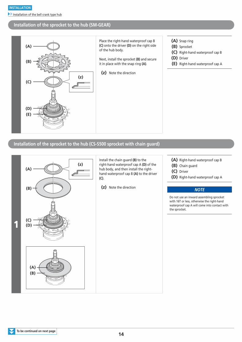
Place the right-hand waterproof cap B (C) onto the driver (D) on the right side of the hub body.
Next, install the sprocket (B) and secure it in place with the snap ring (A).
(z) Note the direction
(A) Snap ring
(B) Sprocket
(C) Right-hand waterproof cap B
(D) Driver
(E) Right-hand waterproof cap A
Installation of the sprocket to the hub (CS-S500 sprocket with chain guard)
1
(A)
(B)
(C)(D)
(z)
(B)(A)
Install the chain guard (B) to the right-hand waterproof cap A (D) of the hub body, and then install the right-hand waterproof cap B (A) to the driver (C).
(z) Note the direction
(A) Right-hand waterproof cap B
(B) Chain guard
(C) Driver
(D) Right-hand waterproof cap A
NOTE
Do not use an inward assembling sprocket with 16T or less, otherwise the right-hand waterproof cap A will come into contact with the sprocket.
15
INSTALLATION
Installation of the bell crank type hub
2(D)(C)
(B)
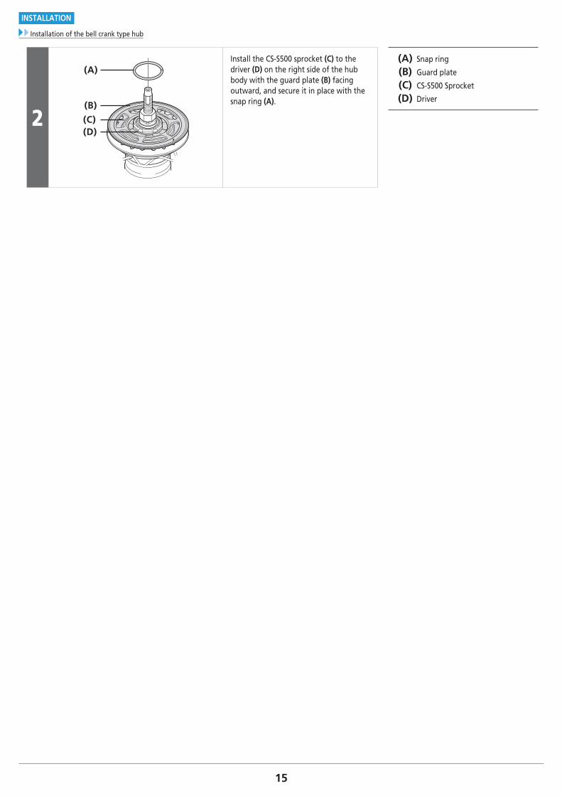
(A)Install the CS-S500 sprocket (C) to the driver (D) on the right side of the hub body with the guard plate (B) facing outward, and secure it in place with the snap ring (A).
(A) Snap ring
(B) Guard plate
(C) CS-S500 Sprocket
(D) Driver
16To be continued on next page
INSTALLATION
Installation of the bell crank type hub
Installation of the hub to the frame (for disc brakes)
1
(A) (B) (C)
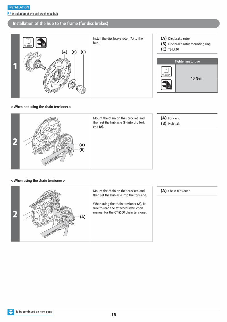
Install the disc brake rotor (A) to the hub.
(A) Disc brake rotor
(B) Disc brake rotor mounting ring
(C) TL-LR10
Tightening torque
40 N·m
< When not using the chain tensioner >
2 (A)(B)
Mount the chain on the sprocket, and then set the hub axle (B) into the fork end (A).
(A) Fork end
(B) Hub axle
< When using the chain tensioner >
2 (A)
Mount the chain on the sprocket, and then set the hub axle into the fork end.
When using the chain tensioner (A), be sure to read the attached instruction manual for the CT-S500 chain tensioner.
(A) Chain tensioner
17To be continued on next page
INSTALLATION
Installation of the bell crank type hub
3
(A)
(z)
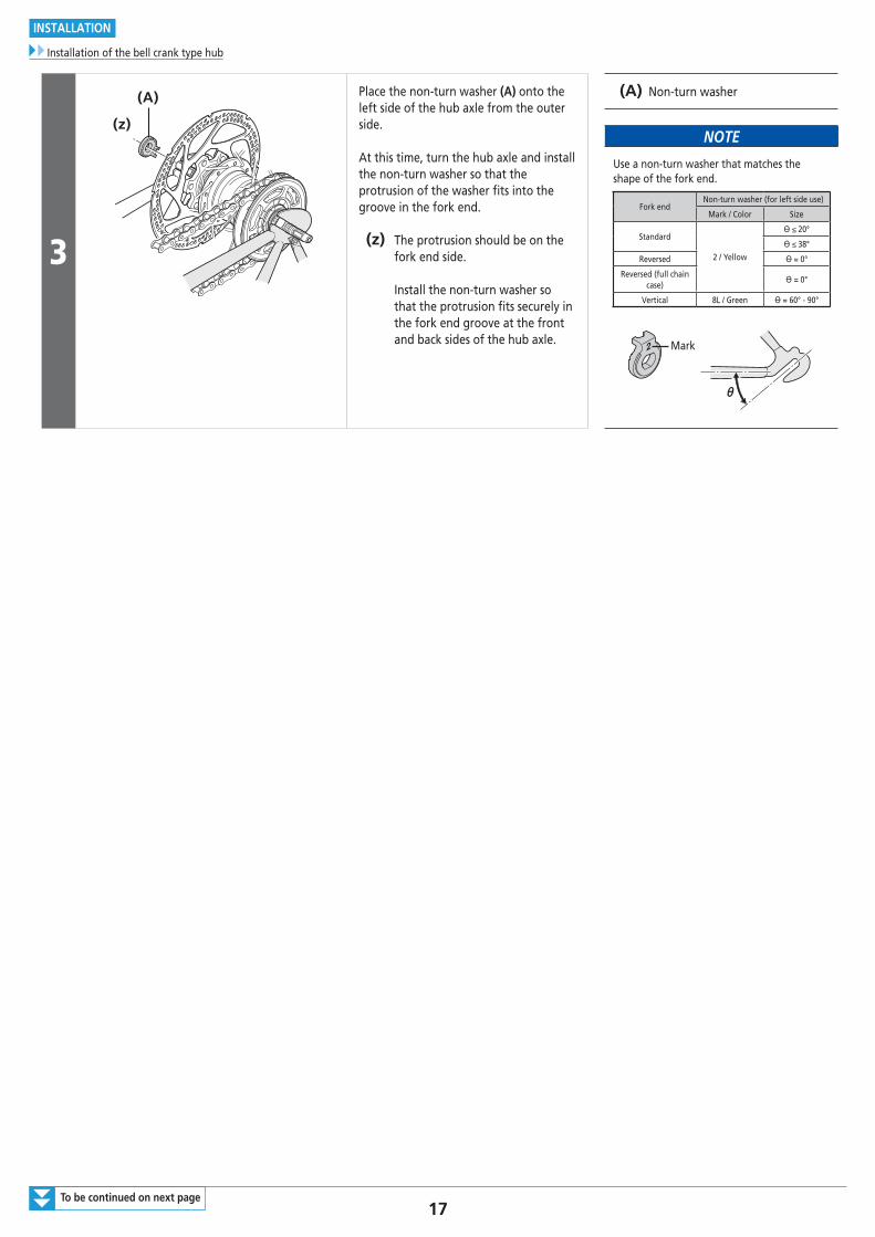
Place the non-turn washer (A) onto the left side of the hub axle from the outer side.
At this time, turn the hub axle and install the non-turn washer so that the protrusion of the washer fits into the groove in the fork end.
(z) The protrusion should be on the fork end side. Install the non-turn washer so that the protrusion fits securely in the fork end groove at the front and back sides of the hub axle.
(A) Non-turn washer
NOTE
Use a non-turn washer that matches the shape of the fork end.
Fork endNon-turn washer (for left side use)
Mark / Color Size
Standard
2 / Yellow
ϴ ≤ 20°
ϴ ≤ 38°
Reversed ϴ = 0°
Reversed (full chain case)
ϴ = 0°
Vertical 8L / Green ϴ = 60° - 90°
Mark
18
INSTALLATION
Installation of the bell crank type hub
4
(A)(B)
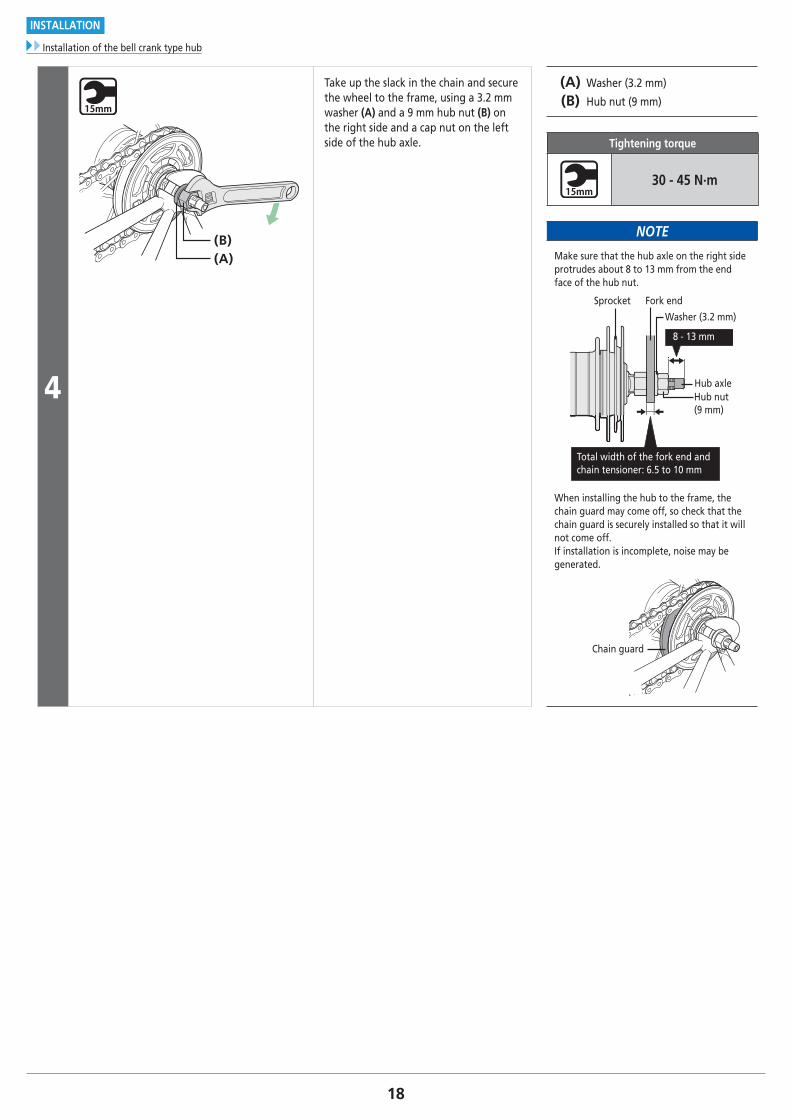
Take up the slack in the chain and secure the wheel to the frame, using a 3.2 mm washer (A) and a 9 mm hub nut (B) on the right side and a cap nut on the left side of the hub axle.
(A) Washer (3.2 mm)
(B) Hub nut (9 mm)
Tightening torque
30 - 45 N·m
NOTE
Make sure that the hub axle on the right side protrudes about 8 to 13 mm from the end face of the hub nut.
Fork end
Hub axleHub nut (9 mm)
Washer (3.2 mm)
Sprocket
8 - 13 mm
Total width of the fork end and chain tensioner: 6.5 to 10 mm
When installing the hub to the frame, the chain guard may come off, so check that the chain guard is securely installed so that it will not come off.If installation is incomplete, noise may be generated.
Chain guard
19To be continued on next page
INSTALLATION
Installation of the bell crank type hub
Installation of the hub to the frame (for roller brakes)
1
(A) (B)
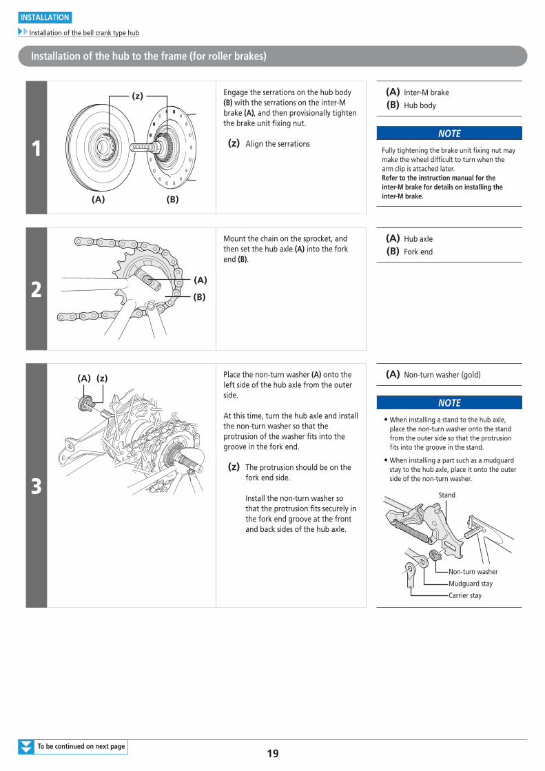
(z) Engage the serrations on the hub body (B) with the serrations on the inter-M brake (A), and then provisionally tighten the brake unit fixing nut.
(z) Align the serrations
(A) Inter-M brake
(B) Hub body
NOTE
Fully tightening the brake unit fixing nut may make the wheel difficult to turn when the arm clip is attached later.Refer to the instruction manual for the inter-M brake for details on installing the inter-M brake.
2(A)
(B)
Mount the chain on the sprocket, and then set the hub axle (A) into the fork end (B).
(A) Hub axle
(B) Fork end
3
(A) (z) Place the non-turn washer (A) onto the left side of the hub axle from the outer side.
At this time, turn the hub axle and install the non-turn washer so that the protrusion of the washer fits into the groove in the fork end.
(z) The protrusion should be on the fork end side. Install the non-turn washer so that the protrusion fits securely in the fork end groove at the front and back sides of the hub axle.
(A) Non-turn washer (gold)
NOTE
• When installing a stand to the hub axle, place the non-turn washer onto the stand from the outer side so that the protrusion fits into the groove in the stand.
• When installing a part such as a mudguard stay to the hub axle, place it onto the outer side of the non-turn washer.
Non-turn washer
Mudguard stay
Carrier stay
Stand
20To be continued on next page
INSTALLATION
Installation of the bell crank type hub
4
(C)
(D)(A) (B)
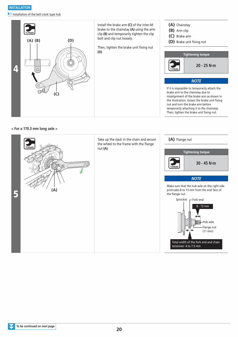
Install the brake arm (C) of the inter-M brake to the chainstay (A) using the arm clip (B) and temporarily tighten the clip bolt and clip nut loosely.
Then, tighten the brake unit fi xing nut (D).
(A) Chainstay
(B) Arm clip
(C) Brake arm
(D) Brake unit fi xing nut
Tightening torque
20 - 25 N·m
NOTE
If it is impossible to temporarily attach the brake arm to the chainstay due to misalignment of the brake arm as shown in the illustration, loosen the brake unit fi xing nut and turn the brake arm before temporarily attaching it to the chainstay. Then, tighten the brake unit fi xing nut.
< For a 170.3 mm long axle >
5(A)
Take up the slack in the chain and secure the wheel to the frame with the fl ange nut (A).
(A) Flange nut
Tightening torque
30 - 45 N·m
NOTE
Make sure that the hub axle on the right side protrudes 8 to 13 mm from the end face of the fl ange nut.
8 - 13 mm
Total width of the fork end and chain tensioner: 4 to 7.5 mm
Sprocket
Hub axle
Flange nut (11 mm)
Fork end
21To be continued on next page
INSTALLATION
Installation of the bell crank type hub
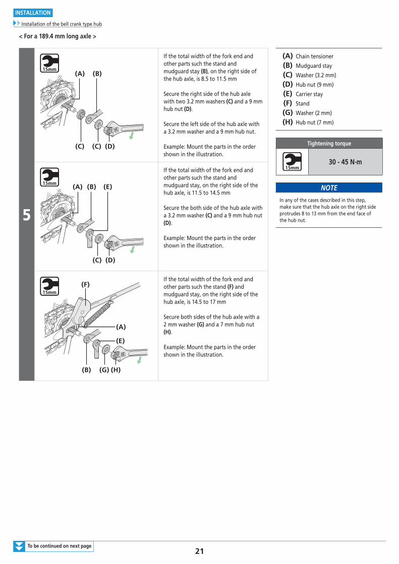
< For a 189.4 mm long axle >
5
(C) (C) (D)
(A) (B)
If the total width of the fork end and other parts such the stand and mudguard stay (B), on the right side of the hub axle, is 8.5 to 11.5 mm
Secure the right side of the hub axle with two 3.2 mm washers (C) and a 9 mm hub nut (D).
Secure the left side of the hub axle with a 3.2 mm washer and a 9 mm hub nut.
Example: Mount the parts in the order shown in the illustration.
(A) Chain tensioner
(B) Mudguard stay
(C) Washer (3.2 mm)
(D) Hub nut (9 mm)
(E) Carrier stay
(F) Stand
(G) Washer (2 mm)
(H) Hub nut (7 mm)
Tightening torque
30 - 45 N·m
NOTE
In any of the cases described in this step, make sure that the hub axle on the right side protrudes 8 to 13 mm from the end face of the hub nut.
(C) (D)
(A) (B) (E)
If the total width of the fork end and other parts such the stand and mudguard stay, on the right side of the hub axle, is 11.5 to 14.5 mm
Secure the both side of the hub axle with a 3.2 mm washer (C) and a 9 mm hub nut (D).
Example: Mount the parts in the order shown in the illustration.
(G)(B) (H)
(F)
(E)
(A)
If the total width of the fork end and other parts such the stand (F) and mudguard stay, on the right side of the hub axle, is 14.5 to 17 mm
Secure both sides of the hub axle with a 2 mm washer (G) and a 7 mm hub nut (H).
Example: Mount the parts in the order shown in the illustration.
22
INSTALLATION
Installation of the bell crank type hub
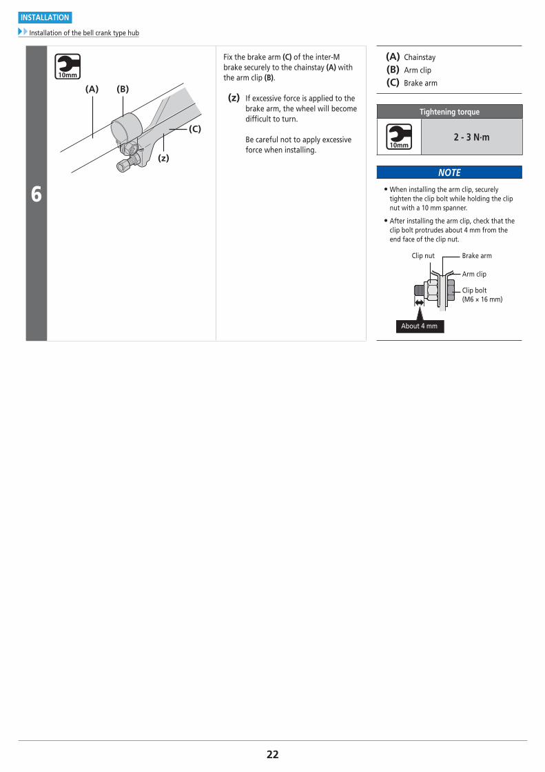
6
(C)
(B)
(z)
(A)
Fix the brake arm (C) of the inter-M brake securely to the chainstay (A) with the arm clip (B).
(z) If excessive force is applied to the brake arm, the wheel will become diffi cult to turn.
Be careful not to apply excessive force when installing.
(A) Chainstay
(B) Arm clip
(C) Brake arm
Tightening torque
2 - 3 N·m
NOTE
• When installing the arm clip, securely tighten the clip bolt while holding the clip nut with a 10 mm spanner.
• After installing the arm clip, check that the clip bolt protrudes about 4 mm from the end face of the clip nut.
About 4 mm
Arm clip
Clip bolt(M6 × 16 mm)
Brake armClip nut
23
INSTALLATION
Installation of the bell crank type hub
Installing the brake cable
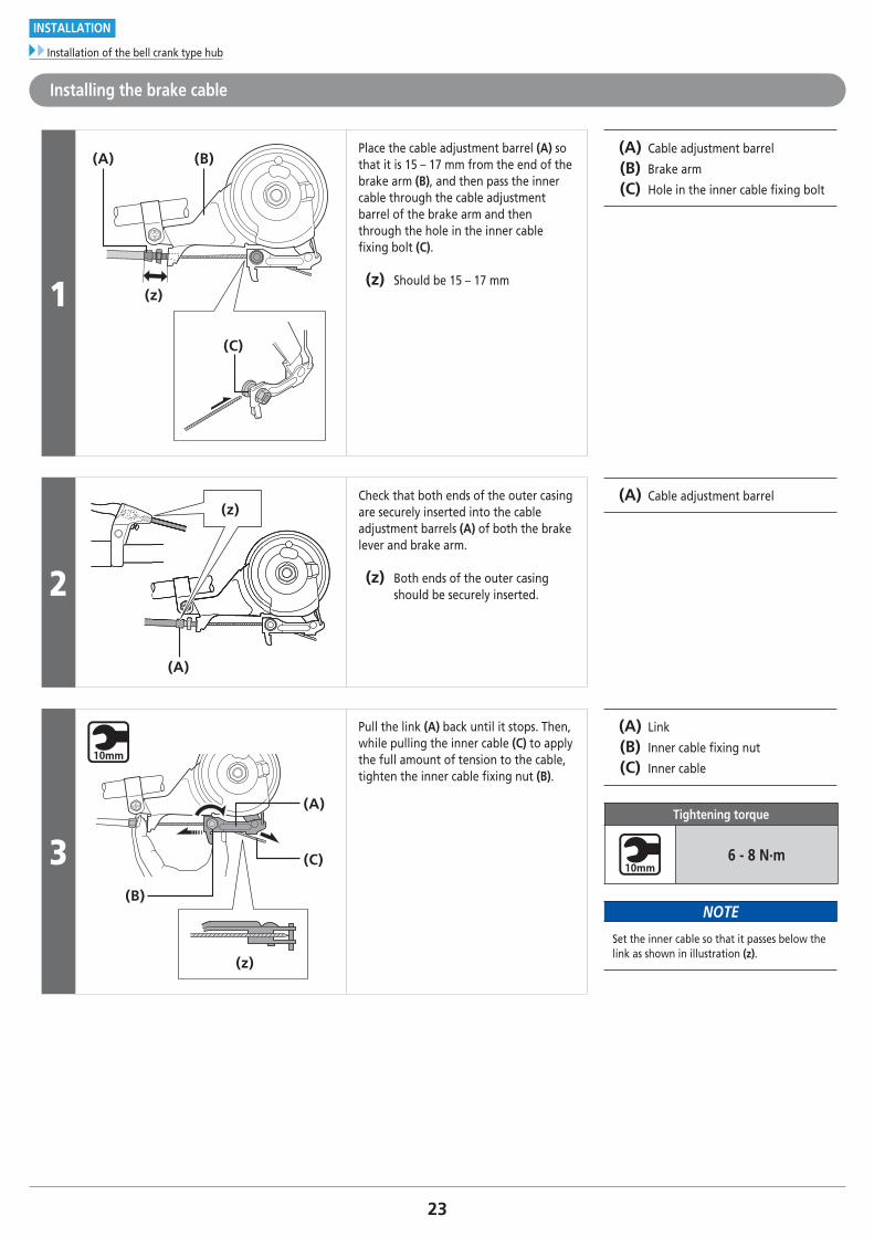
1 (z)
(C)
(A) (B)Place the cable adjustment barrel (A) so that it is 15 – 17 mm from the end of the brake arm (B), and then pass the inner cable through the cable adjustment barrel of the brake arm and then through the hole in the inner cable fi xing bolt (C).
(z) Should be 15 – 17 mm
(A) Cable adjustment barrel
(B) Brake arm
(C) Hole in the inner cable fi xing bolt
2
(z)
(A)
Check that both ends of the outer casing are securely inserted into the cable adjustment barrels (A) of both the brake lever and brake arm.
(z) Both ends of the outer casing should be securely inserted.
(A) Cable adjustment barrel
3
(z)
(A)
(C)
(B)
Pull the link (A) back until it stops. Then, while pulling the inner cable (C) to apply the full amount of tension to the cable, tighten the inner cable fi xing nut (B).
(A) Link
(B) Inner cable fi xing nut
(C) Inner cable
Tightening torque
6 - 8 N·m
NOTE
Set the inner cable so that it passes below the link as shown in illustration (z).
24
INSTALLATION
Installation of the bell crank type hub
Adjusting the brake cable
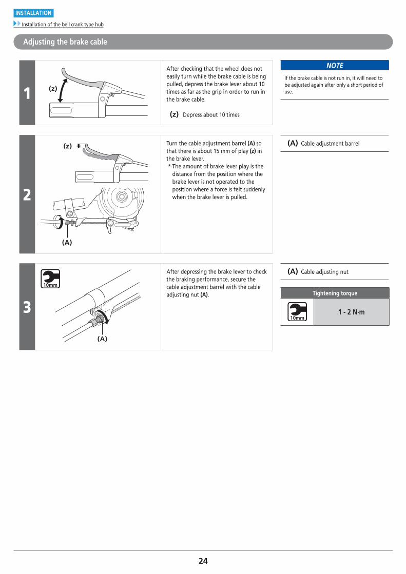
1 (z)
After checking that the wheel does not easily turn while the brake cable is being pulled, depress the brake lever about 10 times as far as the grip in order to run in the brake cable.
(z) Depress about 10 times
NOTE
If the brake cable is not run in, it will need to be adjusted again after only a short period of use.
2
(z)
(A)
Turn the cable adjustment barrel (A) so that there is about 15 mm of play (z) in the brake lever.* The amount of brake lever play is the
distance from the position where the brake lever is not operated to the position where a force is felt suddenly when the brake lever is pulled.
(A) Cable adjustment barrel
3
(A)
After depressing the brake lever to check the braking performance, secure the cable adjustment barrel with the cable adjusting nut (A).
(A) Cable adjusting nut
Tightening torque
1 - 2 N·m
25To be continued on next page
INSTALLATION
Installation of the bell crank type hub
Installation of the hub to the frame (for coaster brakes)
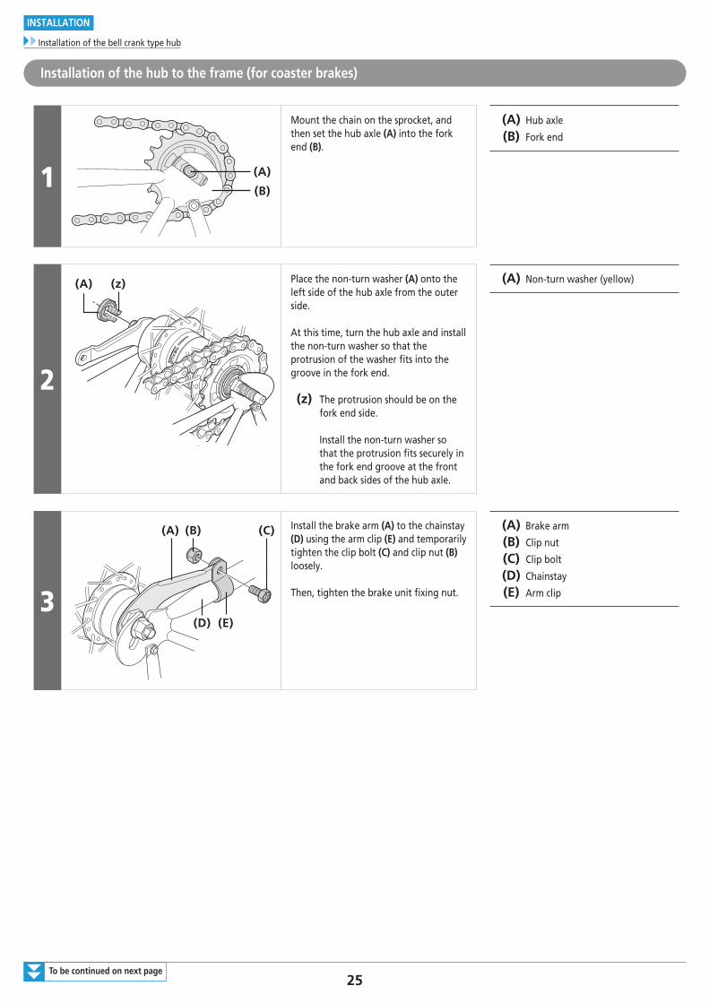
1 (A)
(B)
Mount the chain on the sprocket, and then set the hub axle (A) into the fork end (B).
(A) Hub axle
(B) Fork end
2
(A) (z) Place the non-turn washer (A) onto the left side of the hub axle from the outer side.
At this time, turn the hub axle and install the non-turn washer so that the protrusion of the washer fits into the groove in the fork end.
(z) The protrusion should be on the fork end side. Install the non-turn washer so that the protrusion fits securely in the fork end groove at the front and back sides of the hub axle.
(A) Non-turn washer (yellow)
3
(A) (B) (C)
(D) (E)
Install the brake arm (A) to the chainstay (D) using the arm clip (E) and temporarily tighten the clip bolt (C) and clip nut (B) loosely.
Then, tighten the brake unit fixing nut.
(A) Brake arm
(B) Clip nut
(C) Clip bolt
(D) Chainstay
(E) Arm clip
26To be continued on next page
INSTALLATION
Installation of the bell crank type hub
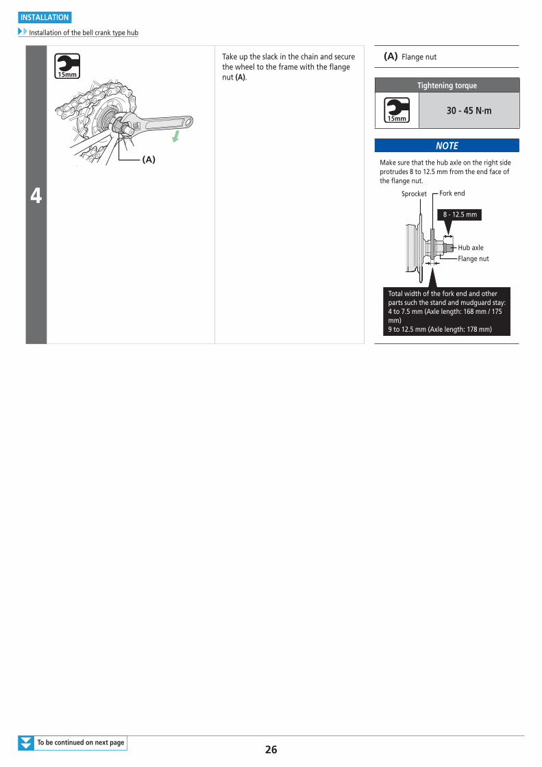
4
(A)
Take up the slack in the chain and secure the wheel to the frame with the fl ange nut (A).
(A) Flange nut
Tightening torque
30 - 45 N·m
NOTE
Make sure that the hub axle on the right side protrudes 8 to 12.5 mm from the end face of the fl ange nut.
Sprocket
Hub axle
Flange nut
Fork end
8 - 12.5 mm
Total width of the fork end and other parts such the stand and mudguard stay:4 to 7.5 mm (Axle length: 168 mm / 175 mm)9 to 12.5 mm (Axle length: 178 mm)
27
INSTALLATION
Installation of the bell crank type hub
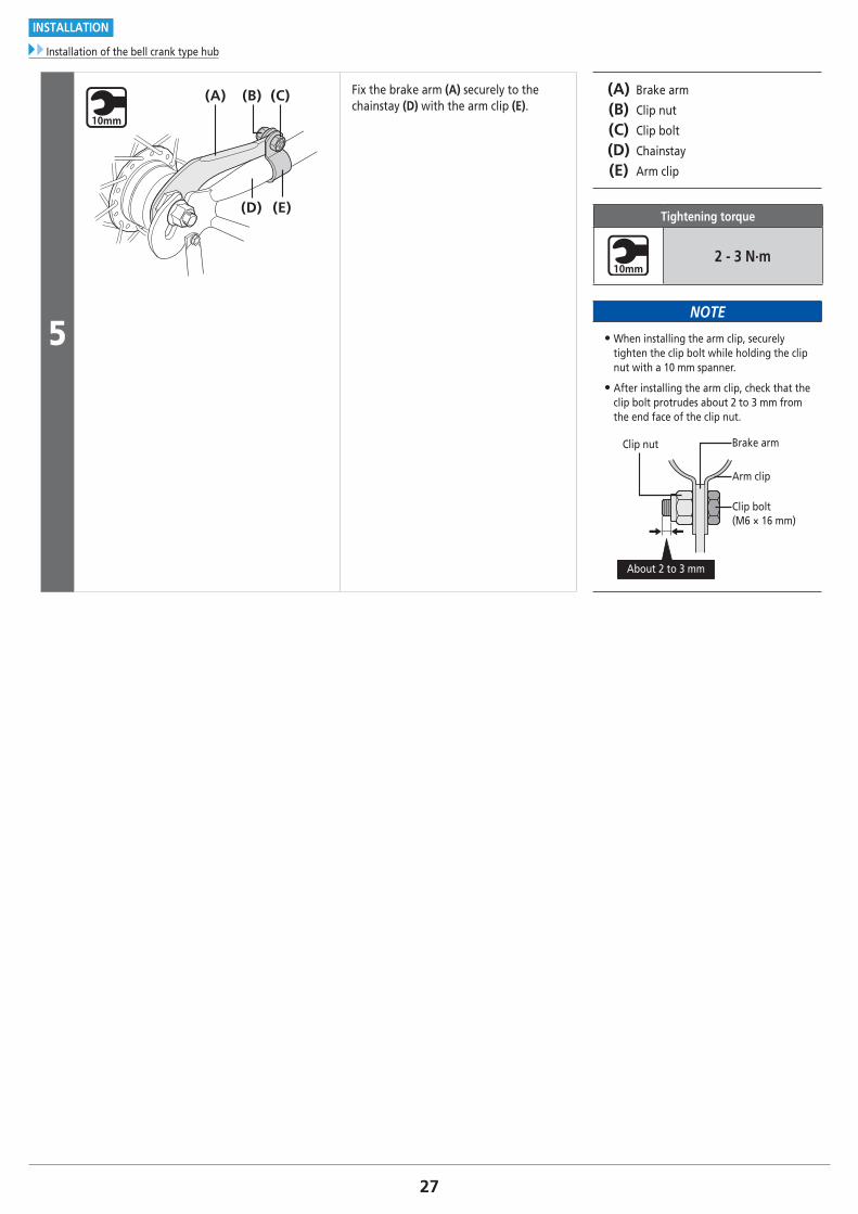
5
(A)
(D)
(B)
(E)
(C) Fix the brake arm (A) securely to the chainstay (D) with the arm clip (E).
(A) Brake arm
(B) Clip nut
(C) Clip bolt
(D) Chainstay
(E) Arm clip
Tightening torque
2 - 3 N·m
NOTE
• When installing the arm clip, securely tighten the clip bolt while holding the clip nut with a 10 mm spanner.
• After installing the arm clip, check that the clip bolt protrudes about 2 to 3 mm from the end face of the clip nut.
About 2 to 3 mm
Clip nut Brake arm
Arm clip
Clip bolt(M6 × 16 mm)
28
INSTALLATION
Installation of the bell crank type hub
Installation of the bell crank
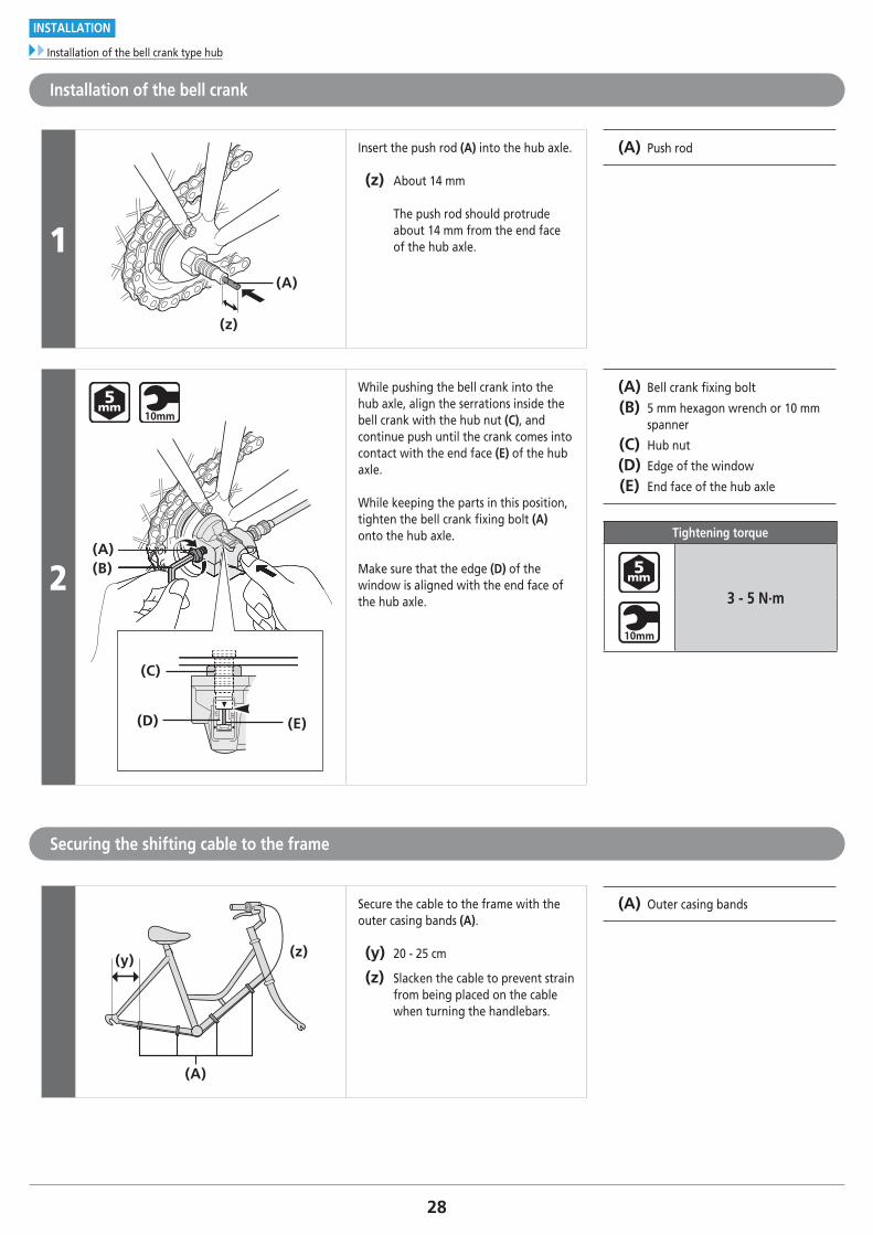
1(A)
(z)
Insert the push rod (A) into the hub axle.
(z) About 14 mm
The push rod should protrude about 14 mm from the end face of the hub axle.
(A) Push rod
2(A)(B)
(C)
(D) (E)
While pushing the bell crank into the hub axle, align the serrations inside the bell crank with the hub nut (C), and continue push until the crank comes into contact with the end face (E) of the hub axle.
While keeping the parts in this position, tighten the bell crank fi xing bolt (A) onto the hub axle.
Make sure that the edge (D) of the window is aligned with the end face of the hub axle.
(A) Bell crank fi xing bolt
(B) 5 mm hexagon wrench or 10 mm spanner
(C) Hub nut
(D) Edge of the window
(E) End face of the hub axle
Tightening torque
3 - 5 N·m
Securing the shifting cable to the frame
(y) (z)
(A)
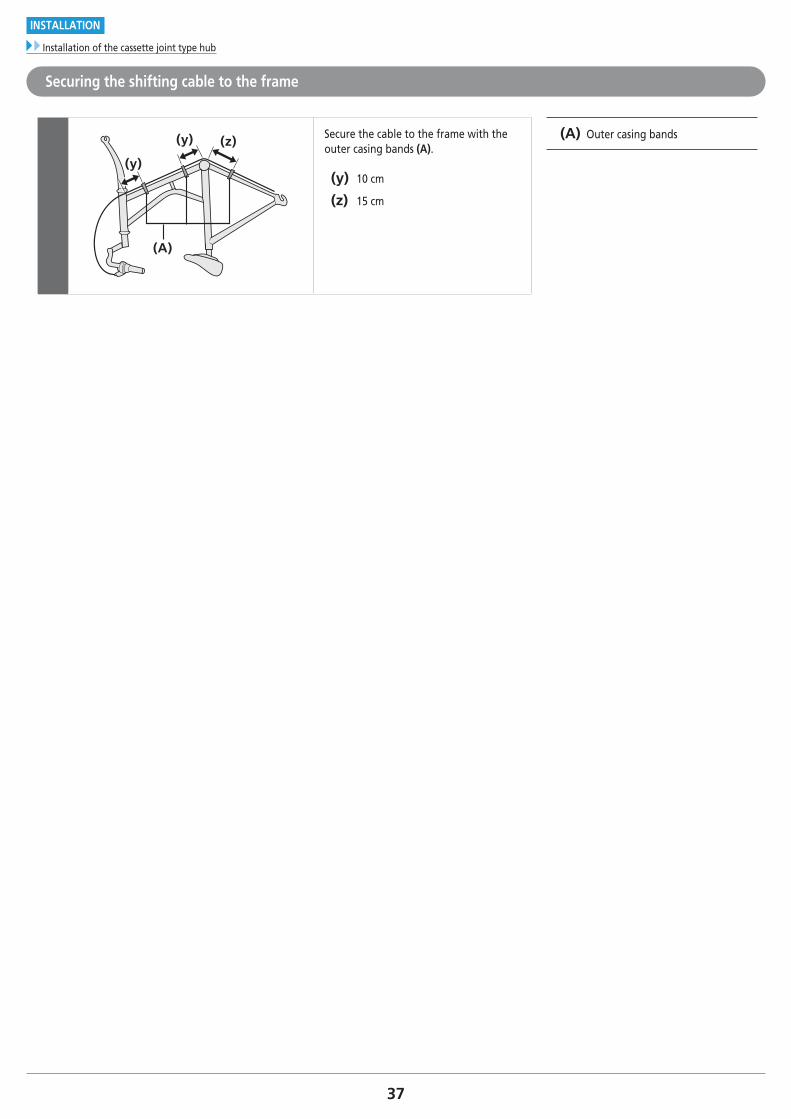
Secure the cable to the frame with the outer casing bands (A).
(y) 20 - 25 cm
(z) Slacken the cable to prevent strain from being placed on the cable when turning the handlebars.
(A) Outer casing bands
29To be continued on next page
INSTALLATION
Installation of the cassette joint type hub
� Installation of the cassette joint type hub
Installation of the shifting cable
1
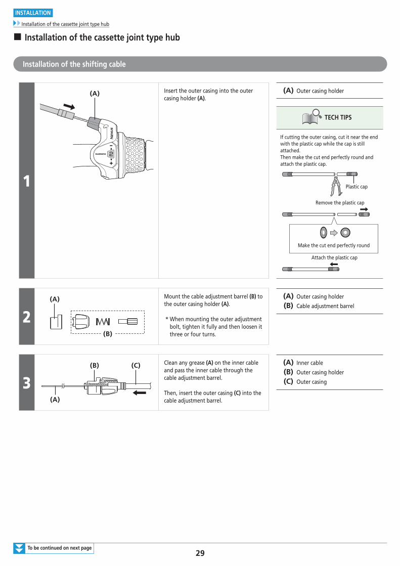
(A) Insert the outer casing into the outer casing holder (A).
(A) Outer casing holder
TECH TIPS
If cutting the outer casing, cut it near the end with the plastic cap while the cap is still attached.Then make the cut end perfectly round and attach the plastic cap.
Plastic cap
Make the cut end perfectly round
Remove the plastic cap
Attach the plastic cap
2(A)
(B)
Mount the cable adjustment barrel (B) to the outer casing holder (A).
* When mounting the outer adjustment bolt, tighten it fully and then loosen it three or four turns.
(A) Outer casing holder
(B) Cable adjustment barrel
3(A)
(B) (C) Clean any grease (A) on the inner cable and pass the inner cable through the cable adjustment barrel.
Then, insert the outer casing (C) into the cable adjustment barrel.
(A) Inner cable
(B) Outer casing holder
(C) Outer casing
30
INSTALLATION
Installation of the cassette joint type hub
4 (C)(B)(A)
(z)
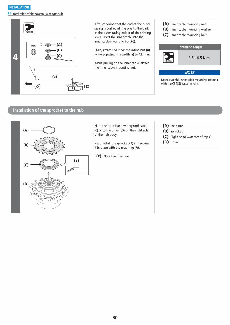
After checking that the end of the outer casing is pushed all the way to the back of the outer casing holder of the shifting lever, insert the inner cable into the inner cable mounting bolt (C).
Then, attach the inner mounting nut (A) while adjusting the width (z) to 127 mm.
While pulling on the inner cable, attach the inner cable mounting nut.
(A) Inner cable mounting nut
(B) Inner cable mounting washer
(C) Inner cable mounting bolt
Tightening torque
3.5 - 4.5 N·m
NOTE
Do not use this inner cable mounting bolt unit with the CJ-4S30 cassette joint.
Installation of the sprocket to the hub
(z)
(A)
(B)
(C)
(D)
Place the right-hand waterproof cap C (C) onto the driver (D) on the right side of the hub body.
Next, install the sprocket (B) and secure it in place with the snap ring (A).
(z) Note the direction
(A) Snap ring
(B) Sprocket
(C) Right-hand waterproof cap C
(D) Driver
31
INSTALLATION
Installation of the cassette joint type hub
Installation of the cassette joint to the hub
1
(D)
(A)
(C)
(B)
(z)
(z)
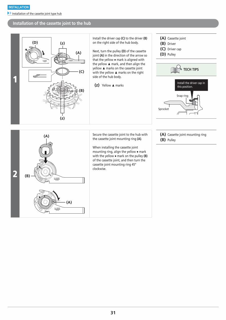
Install the driver cap (C) to the driver (B) on the right side of the hub body.
Next, turn the pulley (D) of the cassette joint (A) in the direction of the arrow so that the yellow ● mark is aligned with the yellow ▲ mark, and then align the yellow ▲ marks on the cassette joint with the yellow ▲ marks on the right side of the hub body.
(z) Yellow ▲ marks
(A) Cassette joint
(B) Driver
(C) Driver cap
(D) Pulley
TECH TIPS
Install the driver cap in this position.
Snap ring
Sprocket
2
(A)
(B)
(A)
Secure the cassette joint to the hub with the cassette joint mounting ring (A).
When installing the cassette joint mounting ring, align the yellow ● mark with the yellow ● mark on the pulley (B) of the cassette joint, and then turn the cassette joint mounting ring 45° clockwise.
(A) Cassette joint mounting ring
(B) Pulley
32To be continued on next page
INSTALLATION
Installation of the cassette joint type hub
Installation of the hub to the frame
1
(A) (B)
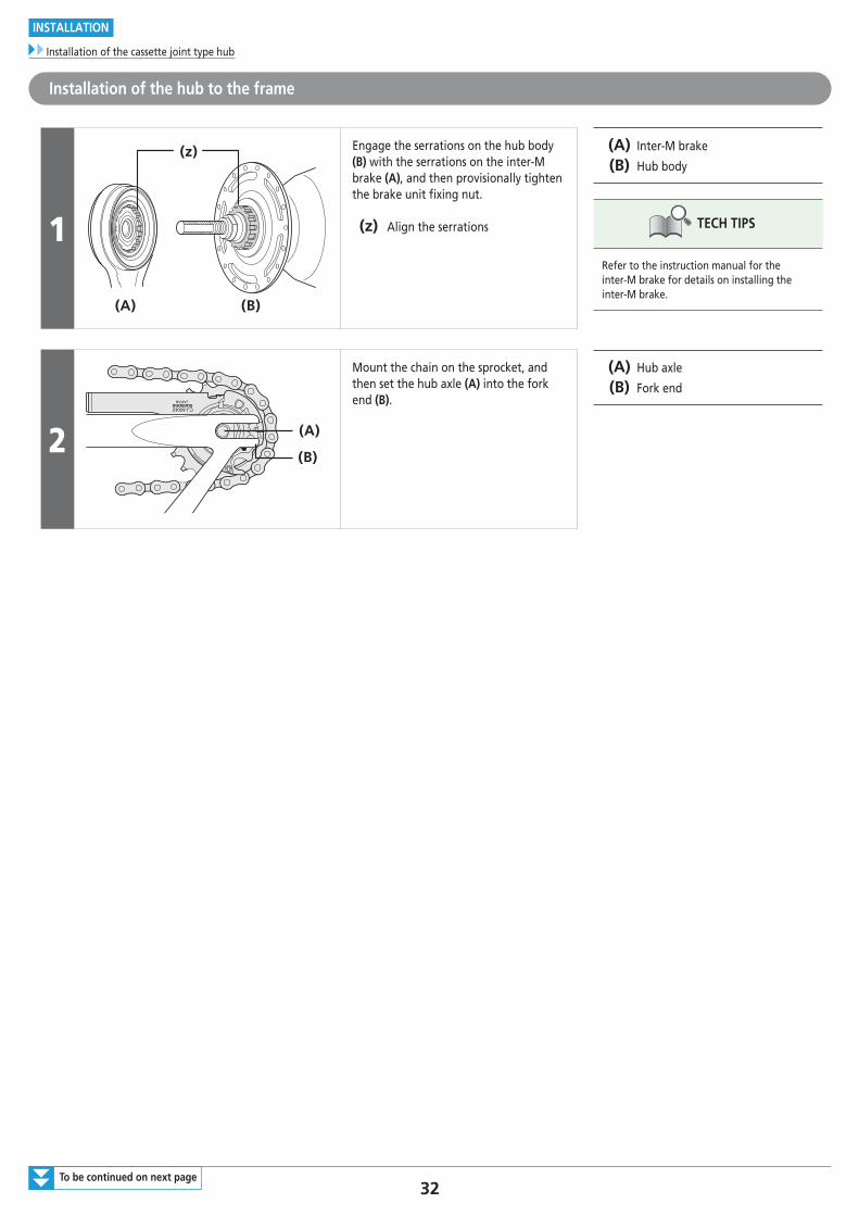
(z) Engage the serrations on the hub body (B) with the serrations on the inter-M brake (A), and then provisionally tighten the brake unit fixing nut.
(z) Align the serrations
(A) Inter-M brake
(B) Hub body
TECH TIPS
Refer to the instruction manual for the inter-M brake for details on installing the inter-M brake.
2 (A)
(B)
Mount the chain on the sprocket, and then set the hub axle (A) into the fork end (B).
(A) Hub axle
(B) Fork end
33To be continued on next page
INSTALLATION
Installation of the cassette joint type hub
3
(A) (C)(B)
(D)(E)
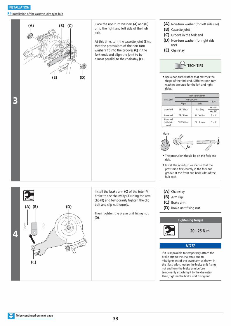
Place the non-turn washers (A) and (D) onto the right and left side of the hub axle.
At this time, turn the cassette joint (B) so that the protrusions of the non-turn washers fit into the grooves (C) in the fork ends and align the joint to be almost parallel to the chainstay (E).
(A) Non-turn washer (for left side use)
(B) Cassette joint
(C) Groove in the fork end
(D) Non-turn washer (for right side use)
(E) Chainstay
TECH TIPS
• Use a non-turn washer that matches the shape of the fork end. Different non-turn washers are used for the left and right sides.
Fork end
Non-turn washer
Mark / ColorSize
Right Left
Standard 7R / Black 7L / Grayϴ ≥ 20°
ϴ ≤ 38°
Reversed 6R / Silver 6L / White ϴ = 0°
Reversed (full chain
case)5R / Yellow 5L / Brown ϴ = 0°
Mark
• The protrusion should be on the fork end side.
• Install the non-turn washer so that the protrusion fits securely in the fork end groove at the front and back sides of the hub axle.
4
(C)
(D)(A) (B)
Install the brake arm (C) of the inter-M brake to the chainstay (A) using the arm clip (B) and temporarily tighten the clip bolt and clip nut loosely.
Then, tighten the brake unit fixing nut (D).
(A) Chainstay
(B) Arm clip
(C) Brake arm
(D) Brake unit fixing nut
Tightening torque
20 - 25 N·m
NOTE
If it is impossible to temporarily attach the brake arm to the chainstay due to misalignment of the brake arm as shown in the illustration, loosen the brake unit fixing nut and turn the brake arm before temporarily attaching it to the chainstay. Then, tighten the brake unit fixing nut.
34To be continued on next page
INSTALLATION
Installation of the cassette joint type hub
5(A) (B)
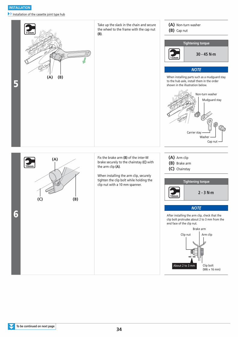
Take up the slack in the chain and secure the wheel to the frame with the cap nut (B).
(A) Non-turn washer
(B) Cap nut
Tightening torque
30 - 45 N·m
NOTE
When installing parts such as a mudguard stay to the hub axle, install them in the order shown in the illustration below.
Non-turn washer
Mudguard stay
WasherCap nut
Carrier stay
6
(C) (B)
(A) Fix the brake arm (B) of the inter-M brake securely to the chainstay (C) with the arm clip (A).
When installing the arm clip, securely tighten the clip bolt while holding the clip nut with a 10 mm spanner.
(A) Arm clip
(B) Brake arm
(C) Chainstay
Tightening torque
2 - 3 N·m
NOTE
After installing the arm clip, check that the clip bolt protrudes about 2 to 3 mm from the end face of the clip nut.
Brake arm
Arm clipClip nut
Clip bolt (M6 × 16 mm)
About 2 to 3 mm
35To be continued on next page
INSTALLATION
Installation of the cassette joint type hub
7
(C) (D)
(A)
(B)
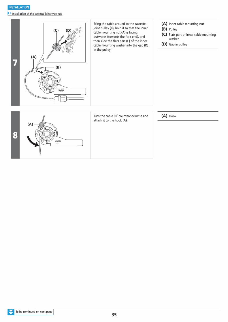
Bring the cable around to the cassette joint pulley (B), hold it so that the inner cable mounting nut (A) is facing outwards (towards the fork end), and then slide the flats part (C) of the inner cable mounting washer into the gap (D) in the pulley.
(A) Inner cable mounting nut
(B) Pulley
(C) Flats part of inner cable mounting washer
(D) Gap in pulley
8(A)
Turn the cable 60˚ counterclockwise and attach it to the hook (A).
(A) Hook
36
INSTALLATION
Installation of the cassette joint type hub
9
(A)
(B) (C)
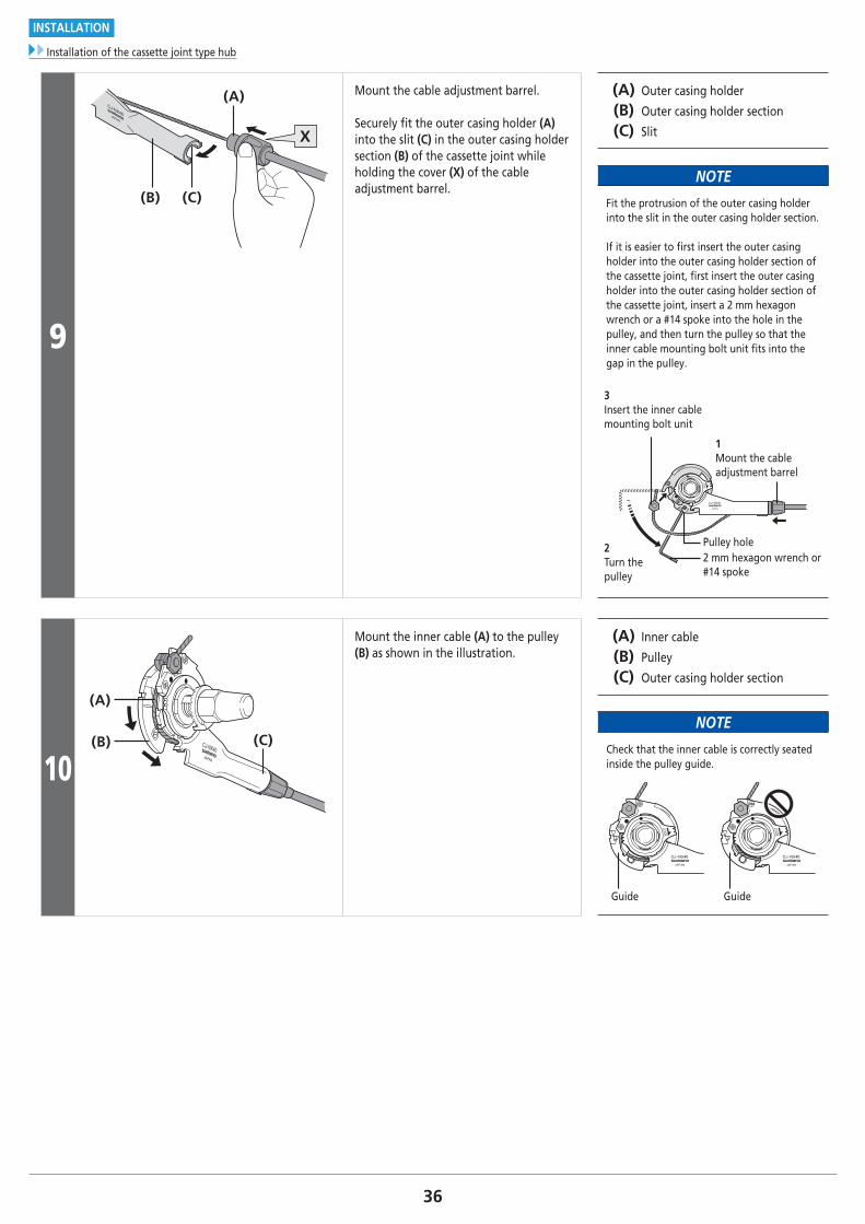
Mount the cable adjustment barrel.
Securely fit the outer casing holder (A) into the slit (C) in the outer casing holder section (B) of the cassette joint while holding the cover (X) of the cable adjustment barrel.
(A) Outer casing holder
(B) Outer casing holder section
(C) Slit
NOTE
Fit the protrusion of the outer casing holder into the slit in the outer casing holder section.
If it is easier to first insert the outer casing holder into the outer casing holder section of the cassette joint, first insert the outer casing holder into the outer casing holder section of the cassette joint, insert a 2 mm hexagon wrench or a #14 spoke into the hole in the pulley, and then turn the pulley so that the inner cable mounting bolt unit fits into the gap in the pulley.
2Turn the pulley
2 mm hexagon wrench or #14 spoke
Pulley hole
1Mount the cable adjustment barrel
3Insert the inner cable mounting bolt unit
10(B)
(A)
(C)
Mount the inner cable (A) to the pulley (B) as shown in the illustration.
(A) Inner cable
(B) Pulley
(C) Outer casing holder section
NOTE
Check that the inner cable is correctly seated inside the pulley guide.
Guide Guide
37
INSTALLATION
Installation of the cassette joint type hub
Securing the shifting cable to the frame
(y)
(y) (z)
(A)
Secure the cable to the frame with the outer casing bands (A).
(y) 10 cm
(z) 15 cm
(A) Outer casing bands
ADJUSTMENT
39
ADJUSTMENT
For bell cranks
ADJUSTMENT
� For bell cranks
1
(A)
(B)(B)
(C) (E)(F)(E)(D)
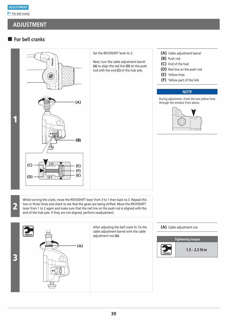
Set the REVOSHIFT lever to 2.
Next, turn the cable adjustment barrel (A) to align the red line (D) on the push rod with the end (C) of the hub axle.
(A) Cable adjustment barrel
(B) Push rod
(C) End of the hub
(D) Red line on the push rod
(E) Yellow lines
(F) Yellow part of the link
NOTE
During adjustment, check the two yellow lines through the window from above.
2While turning the crank, move the REVOSHIFT lever from 3 to 1 then back to 3. Repeat this two or three times and check to see that the gears are being shifted. Move the REVOSHIFT lever from 1 to 2 again and make sure that the red line on the push rod is aligned with the end of the hub axle. If they are not aligned, perform readjustment.
3SET
SET
(A)
After adjusting the bell crank IV, fi x the cable adjustment barrel with the cable adjustment nut (A).
(A) Cable adjustment nut
Tightening torque
1.5 - 2.5 N·m
40
ADJUSTMENT
For cassette joints
� For cassette joints
1
(y)
(z)
(A)
(B)
(C)
(B)
(C)
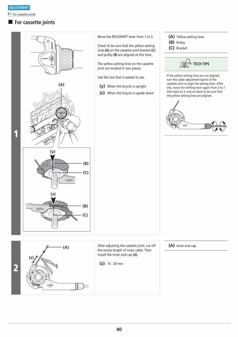
Move the REVOSHIFT lever from 1 to 3.
Check to be sure that the yellow setting lines (A) on the cassette joint bracket (C) and pulley (B) are aligned at this time.
The yellow setting lines on the cassette joint are located in two places.
Use the one that is easiest to see.
(y) When the bicycle is upright
(z) When the bicycle is upside down
(A) Yellow setting lines
(B) Pulley
(C) Bracket
TECH TIPS
If the yellow setting lines are not aligned, turn the cable adjustment barrel of the cassette joint to align the setting lines. After this, move the shifting lever again from 3 to 1 then back to 3, and re-check to be sure that the yellow setting lines are aligned.
2(z)
(A) After adjusting the cassette joint, cut off the excess length of inner cable. Then install the inner end cap (A).
(z) 15 - 20 mm
(A) Inner end cap
MAINTENANCE
42To be continued on next page
MAINTENANCE
Replacement of the shifting cable
MAINTENANCE
� Replacement of the shifting cable
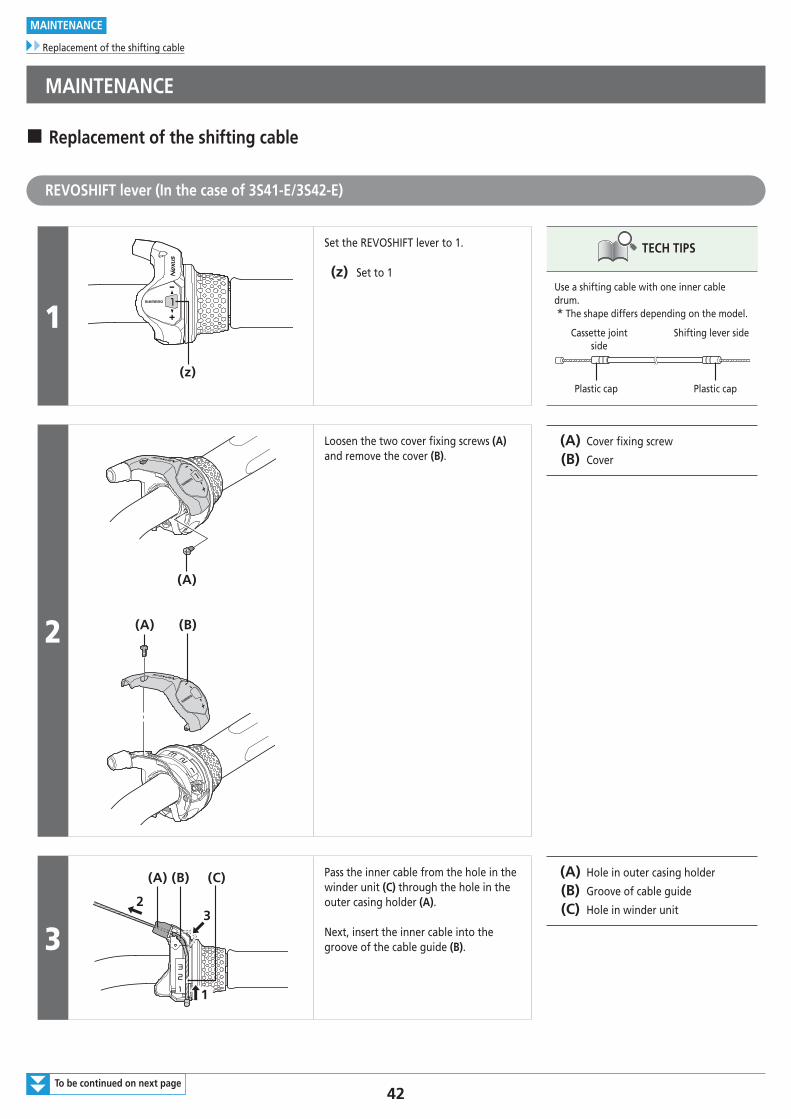
REVOSHIFT lever (In the case of 3S41-E/3S42-E)
1
(z)
Set the REVOSHIFT lever to 1.
(z) Set to 1
TECH TIPS
Use a shifting cable with one inner cable drum.* The shape differs depending on the model.
Cassette joint side
Shifting lever side
Plastic cap Plastic cap
2
(A)
(B)(A)
Loosen the two cover fixing screws (A) and remove the cover (B).
(A) Cover fixing screw
(B) Cover
3
1
32
(A) (B) (C) Pass the inner cable from the hole in the winder unit (C) through the hole in the outer casing holder (A).
Next, insert the inner cable into the groove of the cable guide (B).
(A) Hole in outer casing holder
(B) Groove of cable guide
(C) Hole in winder unit
43
MAINTENANCE
Replacement of the shifting cable
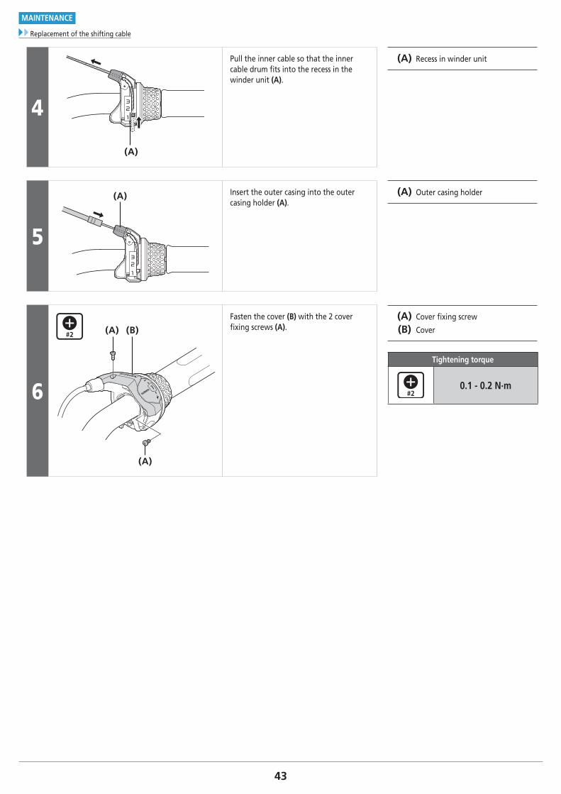
4
(A)
Pull the inner cable so that the inner cable drum fits into the recess in the winder unit (A).
(A) Recess in winder unit
5
(A) Insert the outer casing into the outer casing holder (A).
(A) Outer casing holder
6
(B)(A)
(A)
Fasten the cover (B) with the 2 cover fixing screws (A).
(A) Cover fixing screw
(B) Cover
Tightening torque
0.1 - 0.2 N·m
44To be continued on next page
MAINTENANCE
Replacement of the shifting cable
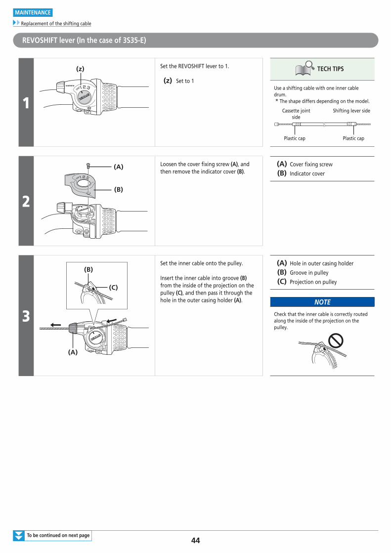
REVOSHIFT lever (In the case of 3S35-E)
1
(z) Set the REVOSHIFT lever to 1.
(z) Set to 1
TECH TIPS
Use a shifting cable with one inner cable drum.* The shape differs depending on the model.
Cassette joint side
Shifting lever side
Plastic cap Plastic cap
2
(A)
(B)
Loosen the cover fixing screw (A), and then remove the indicator cover (B).
(A) Cover fixing screw
(B) Indicator cover
3
(B)
(C)
(A)
Set the inner cable onto the pulley.
Insert the inner cable into groove (B) from the inside of the projection on the pulley (C), and then pass it through the hole in the outer casing holder (A).
(A) Hole in outer casing holder
(B) Groove in pulley
(C) Projection on pulley
NOTE
Check that the inner cable is correctly routed along the inside of the projection on the pulley.
45
MAINTENANCE
Replacement of the shifting cable
4 3
2
1
(B) (C)
(A)
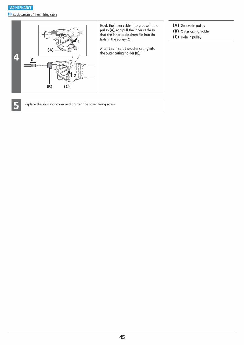
Hook the inner cable into groove in the pulley (A), and pull the inner cable so that the inner cable drum fits into the hole in the pulley (C).
After this, insert the outer casing into the outer casing holder (B).
(A) Groove in pulley
(B) Outer casing holder
(C) Hole in pulley
5 Replace the indicator cover and tighten the cover fixing screw.
46To be continued on next page
MAINTENANCE
Oil maintenance of the internal assembly
� Oil maintenance of the internal assembly
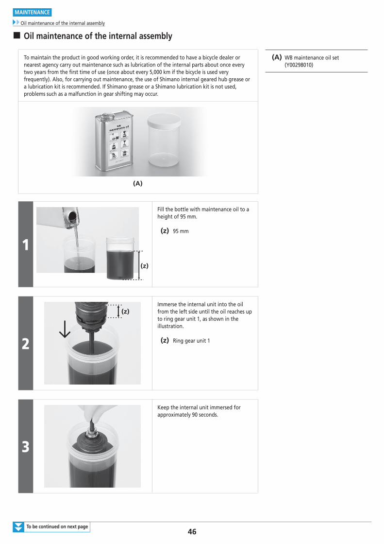
To maintain the product in good working order, it is recommended to have a bicycle dealer or nearest agency carry out maintenance such as lubrication of the internal parts about once every two years from the first time of use (once about every 5,000 km if the bicycle is used very frequently). Also, for carrying out maintenance, the use of Shimano internal geared hub grease or a lubrication kit is recommended. If Shimano grease or a Shimano lubrication kit is not used, problems such as a malfunction in gear shifting may occur.
(A) WB maintenance oil set (Y00298010)
(A)
1(z)
Fill the bottle with maintenance oil to a height of 95 mm.
(z) 95 mm
2
(z)Immerse the internal unit into the oil from the left side until the oil reaches up to ring gear unit 1, as shown in the illustration.
(z) Ring gear unit 1
3
Keep the internal unit immersed for approximately 90 seconds.
47
MAINTENANCE
Oil maintenance of the internal assembly
4
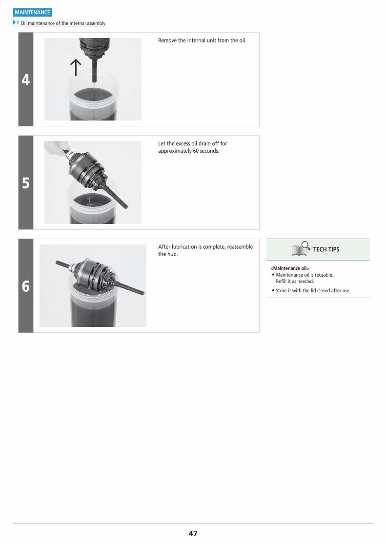
Remove the internal unit from the oil.
5
Let the excess oil drain off for approximately 60 seconds.
6
After lubrication is complete, reassemble the hub.
TECH TIPS
<Maintenance oil> • Maintenance oil is reusable. Refill it as needed.
• Store it with the lid closed after use.

Please note: specifications are subject to change for improvement without notice. (English) © May 2017 by Shimano Inc. ITP